CN101261181B - A device for measuring high reflectivity - Google Patents
A device for measuring high reflectivityDownload PDFInfo
- Publication number
- CN101261181B CN101261181BCN 200810055653CN200810055653ACN101261181BCN 101261181 BCN101261181 BCN 101261181BCN 200810055653CN200810055653CN 200810055653CN 200810055653 ACN200810055653 ACN 200810055653ACN 101261181 BCN101261181 BCN 101261181B
- Authority
- CN
- China
- Prior art keywords
- cavity
- mirror
- plane
- outgoing
- ring
- Prior art date
- Legal status (The legal status is an assumption and is not a legal conclusion. Google has not performed a legal analysis and makes no representation as to the accuracy of the status listed.)
- Expired - Fee Related
Links
- 238000002310reflectometryMethods0.000titleclaimsabstractdescription52
- 230000003287optical effectEffects0.000claimsabstractdescription46
- 238000012360testing methodMethods0.000claimsabstractdescription20
- 238000005516engineering processMethods0.000claimsabstractdescription6
- 239000004065semiconductorSubstances0.000claimsdescription13
- 238000001514detection methodMethods0.000claimsdescription4
- 238000005070samplingMethods0.000claimsdescription3
- 230000005428wave functionEffects0.000claimsdescription3
- 241000931526Acer campestreSpecies0.000claims1
- 238000013481data captureMethods0.000claims1
- 230000001105regulatory effectEffects0.000claims1
- 238000005259measurementMethods0.000abstractdescription16
- 238000000034methodMethods0.000abstractdescription13
- 238000006243chemical reactionMethods0.000abstract1
- 238000010586diagramMethods0.000description3
- 238000000691measurement methodMethods0.000description3
- 230000000694effectsEffects0.000description2
- 230000005284excitationEffects0.000description2
- 230000010354integrationEffects0.000description2
- 230000008878couplingEffects0.000description1
- 238000010168coupling processMethods0.000description1
- 238000005859coupling reactionMethods0.000description1
- 230000007423decreaseEffects0.000description1
- 238000002798spectrophotometry methodMethods0.000description1
- 230000001960triggered effectEffects0.000description1
Images


Landscapes
- Investigating Or Analysing Materials By Optical Means (AREA)
Abstract
Description
Translated fromChinese技术领域technical field
本发明涉及一种用于测量光学元件参数的装置,特别涉及一种用于测量高反射率的装置。The invention relates to a device for measuring optical element parameters, in particular to a device for measuring high reflectivity.
背景技术Background technique
高反射率光学元件在激光系统中的广泛使用迫切要求精确测量高反射率,而传统方法(如分光光度法)无法满足高反射率的测量精度要求。中国专利申请号98114152.8,公开号CN1242516A,公开日期2000年1月26日的发明专利公开了“一种反射镜高反射率的测量方法”,采用脉冲激光系统作光源,入射到两块高反镜组成的光学谐振腔,光电探测器在出射腔镜后接收光腔指数衰减信号,分别确定直腔衰荡时间τ1和折叠腔衰荡时间τ2,计算得到待测镜的反射率R。该方法的缺点是:由于脉冲激光光束质量差、衰荡腔内存在模式竞争等因素,测量精度受到限制;而且,由于所使用的脉冲激光系统造价高,不利于推广使用。中国专利申请号200610011254.9,公开号CN1804572A,公开日期2006年7月19日的发明专利提供了“一种高反镜反射率的测量方法”;2006年9月出版的《中国激光》,龚元,李斌成,第33卷第9期1247-1250页,公开了一种“连续激光光腔衰荡法精确测量高反射率”的方法,它们都提出了一种以连续半导体激光器作光源的高反射率测量方法,用方波调制连续激光,采用锁相方式探测输出信号的振幅衰减和相位延迟,从而得到光腔衰荡时间和高反镜反射率。该方法装置简单、成本低,但激光功率耦合进衰荡腔的效率较低,当腔镜反射率提高到一定程度后,光腔输出信号振幅较小,信噪比下降,使得装置调节比较困难,而且限制了可测最高反射率和测量精度。中国专利申请号200610165082.0,公开号CN1963435A,公开日期2007年5月16日的发明专利“高反镜反射率的测量方法”使连续激光沿衰荡腔光轴入射,当光腔衰荡信号幅值大于设定的阈值时触发关闭激光束,探测指数衰减信号并拟合得到腔镜和测试镜的反射率。该方法装置简单,精度高,但对整个系统的准直要求很高,且必须对腔镜进行精密调节。The widespread use of high reflectivity optical components in laser systems urgently requires accurate measurement of high reflectivity, while traditional methods (such as spectrophotometry) cannot meet the measurement accuracy requirements of high reflectivity. Chinese Patent Application No. 98114152.8, Publication No. CN1242516A, the patent of invention published on January 26, 2000 discloses "a method for measuring the high reflectivity of reflective mirrors", using a pulsed laser system as the light source, incident on two high reflective mirrors The composed optical resonant cavity, the photodetector receives the optical cavity exponential attenuation signal after exiting the cavity mirror, respectively determines the ring-down time τ1 of the straight cavity and the ring-down time τ2 of the folded cavity, and calculates the reflectivity R of the mirror to be tested. The disadvantages of this method are: due to factors such as poor quality of pulsed laser beams and mode competition in the ring-down cavity, the measurement accuracy is limited; moreover, due to the high cost of the pulsed laser system used, it is not conducive to popularization and use. Chinese Patent Application No. 200610011254.9, Publication No. CN1804572A, the invention patent with the publication date of July 19, 2006 provides "a method for measuring the reflectivity of high mirrors";"ChinaLaser" published in September 2006, Gong Yuan, Li Bincheng, Volume 33, No. 9, pages 1247-1250, disclosed a method of "accurate measurement of high reflectance by continuous laser cavity ring-down method". The rate measurement method uses a square wave to modulate a continuous laser, and uses a phase-locked method to detect the amplitude attenuation and phase delay of the output signal, thereby obtaining the ring-down time of the optical cavity and the reflectivity of the high mirror. This method has a simple device and low cost, but the efficiency of laser power coupling into the ring-down cavity is low. When the reflectivity of the cavity mirror is increased to a certain level, the amplitude of the output signal of the optical cavity is small, and the signal-to-noise ratio decreases, making it difficult to adjust the device. , and limits the measurable maximum reflectivity and measurement accuracy. Chinese patent application number 200610165082.0, publication number CN1963435A, the invention patent "measurement method of high mirror reflectivity" published on May 16, 2007 makes the continuous laser incident along the optical axis of the ring-down cavity, when the ring-down signal amplitude of the optical cavity When it is greater than the set threshold, the laser beam is triggered off, and the exponential decay signal is detected and fitted to obtain the reflectivity of the cavity mirror and the test mirror. This method has a simple device and high precision, but requires high collimation of the whole system, and the cavity mirror must be precisely adjusted.
上述现有技术所涉及到的测量高反射率的装置的初始衰荡光腔都采用直腔构型,插入待测平面镜后形成的折叠腔作为测试衰荡腔;光电探测器接收从出射腔镜输出的激光束用于测量衰荡时间和反射率;实际应用中,为了减小腔长测量引入的高反射率测量误差,一般采用较长的衰荡腔,此时直腔作为初始腔将不便于系统集成;在已有的基于光腔衰荡技术的高反射率测量仪器中,光腔衰荡信号通过将出射腔镜输出的光信号经会聚透镜聚焦到一光电探测器上进行探测,一般将出射腔镜、会聚透镜和光电探测器安装在同一底座上,便于在直腔和折叠腔之间切换时同时移动三者;这样一个整体的重量较大,三者集成在一起不仅提高了系统成本,而且不利于直腔/折叠腔切换时光路的精确对准调节;同时,探测器的电源线、信号线在移动时也会造成不便。The initial ring-down optical cavity of the device for measuring high reflectivity involved in the above-mentioned prior art all adopts a straight cavity configuration, and the folded cavity formed after inserting the plane mirror to be tested is used as the test ring-down cavity; The output laser beam is used to measure the ring-down time and reflectivity; in practical applications, in order to reduce the high reflectivity measurement error introduced by the cavity length measurement, a longer ring-down cavity is generally used. At this time, the straight cavity will not be used as the initial cavity. It is convenient for system integration; in the existing high-reflectivity measuring instruments based on optical cavity ring-down technology, the optical cavity ring-down signal is detected by focusing the optical signal output by the exit cavity mirror on a photodetector through a converging lens. Installing the exit cavity mirror, converging lens and photodetector on the same base makes it easy to move the three at the same time when switching between the straight cavity and the folded cavity; the weight of such a whole is relatively large, and the integration of the three not only improves the system Cost, and it is not conducive to the precise alignment and adjustment of the light path when switching between straight cavity and folded cavity; at the same time, the power line and signal line of the detector will also cause inconvenience when moving.
发明内容Contents of the invention
本发明要解决的技术问题是:针对现有技术中直腔/折叠腔切换时给系统带来的不足,提供一种初始衰荡光腔为折叠腔的测量高反射率的装置,该装置稳定性好、方便调节和测量。The technical problem to be solved by the present invention is to provide a device for measuring high reflectivity in which the initial ring-down optical cavity is a folded cavity, and the device is stable Good performance, convenient adjustment and measurement.
本发明解决其技术问题所采用的技术方案是:一种用于测量高反射率的装置,其中:光电探测器7将光信号转换成电信号,由数据采集卡8记录并输入计算机9处理及存储,计算机9控制数据采集卡8的采样率、采集数据点长度以及采集电压最大幅值;其特征在于:入射腔镜3和出射腔镜5与平面高反镜4共同构成稳定的光学谐振腔作为初始衰荡光腔,入射腔镜3和平面高反镜4位于同一直线上,构成初始衰荡光腔的入射臂,出射腔镜5和平面高反镜4位于另一条直线上,构成初始衰荡光腔的出射臂,总腔长为L,入射臂和出射臂之间的夹角为θ;测试时,由光源1发出的光束经匹配透镜2进入上述初始衰荡光腔,会聚透镜6和光电探测器7置于平面高反镜4后搜集和探测出射的光束;由光腔衰荡技术探测并通过计算机9拟合得到初始光腔衰荡时间τ1;然后在出射臂插入待测平面镜14,调节出射腔镜5,形成稳定的测试腔,再由光腔衰荡技术探测并通过计算机9拟合得到测试腔衰荡时间τ2;通过待测平面高反镜的反射率公式计算,便可得到待测平面高反镜的反射率。The technical solution adopted by the present invention to solve its technical problems is: a device for measuring high reflectivity, wherein: the
所述光源1可采用光强可调制的连续半导体激光器,此时函数发生卡10与计算机9相连,计算机9控制函数发生卡10的调制频率、调制振幅以及偏置电压,函数发生卡10输出的方波函数用于调制光源1所采用的半导体激光器的激励电压;光源1也采用脉冲激光器,此时不需要函数发生卡10调制光源1,光源1直接输出激光脉冲。Described
所述的光源1的激光波长若不在可见波段,则利用反射镜12和分光镜13引入准直光束激光器11发出的可见激光束,用于调节衰荡腔。If the laser wavelength of the
所述的会聚透镜6和光电探测器7搜集和探测平行于入射臂方向或出射臂方向的出射激光束或同时搜集和探测两个方向的出射激光束。The converging
所述的入射臂比出射臂短,两者之间的夹角θ满足5°≤θ≤45°。The incident arm is shorter than the outgoing arm, and the angle θ between the two satisfies 5°≤θ≤45°.
所述的入射腔镜3的反射率R1和平面高反镜4的反射率R2满足0.998≤R1≤0.9999,0.998≤R2≤0.9999,出射腔镜5的反射率R3满足R3≥0.9995,并且出射腔镜5的反射率R3高于入射腔镜3的反射率R1和平面高反镜4的反射率R2。The reflectivity R1 of the
所述在出射臂插入待测平面镜14后所形成的测试角度α,即插入的待测平面镜14的法线方向与初始衰荡腔出射臂的夹角α为1~85度。The test angle α formed after the exit arm is inserted into the
本发明与现有技术相比所具有的优点:本发明所改进的装置通过引入一块平面高反镜,与两块分别作为入射腔镜和出射腔镜的平凹腔镜共同构成的折叠腔作为初始衰荡光腔,然后在出射臂插入待测平面镜,调节出射腔镜,形成稳定的测试腔,这种衰荡腔构型缩小了系统的体积;光腔衰荡信号改由对平面高反镜出射的光信号经聚焦后由光电探测器探测,这样在插入待测镜以后仅需移动出射腔镜便可形成稳定的测试腔,减少了高反射率测量过程中需要移动的元件数量,提高了测量系统的稳定性;而且作为激光输出镜的平面高反镜在测量过程中无需调节,出射腔镜单独存在,容易调节。Compared with the prior art, the present invention has the advantages that the improved device of the present invention introduces a flat high-reflection mirror, and a folded cavity composed of two plano-concave cavity mirrors that are respectively used as an incident cavity mirror and an exit cavity mirror. Initially ring down the optical cavity, then insert the plane mirror to be tested in the outgoing arm, adjust the outgoing cavity mirror, and form a stable test cavity. This ring-down cavity configuration reduces the volume of the system; The optical signal emitted by the mirror is focused and detected by the photodetector, so that after inserting the mirror to be tested, it is only necessary to move the exit cavity mirror to form a stable test cavity, which reduces the number of components that need to be moved during the measurement of high reflectivity and improves The stability of the measurement system is improved; moreover, the planar high-reflection mirror used as the laser output mirror does not need to be adjusted during the measurement process, and the exit cavity mirror exists independently and is easy to adjust.
附图说明Description of drawings
下面结合附图及具体实施方式对本发明作进一步详细说明。The present invention will be described in further detail below in conjunction with the accompanying drawings and specific embodiments.
图1为本发明的基于连续半导体激光器的高反射率测量装置示意图;Fig. 1 is the schematic diagram of the high reflectance measuring device based on continuous semiconductor laser of the present invention;
图2为本发明的光电探测器搜集输出激光束的示意图;Fig. 2 is the schematic diagram that the photodetector of the present invention collects the output laser beam;
图3为本发明的基于脉冲激光器的高反射率测量装置示意图;Fig. 3 is the schematic diagram of the high reflectance measuring device based on the pulsed laser of the present invention;
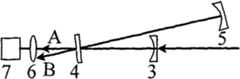
图中:1为光源、2为匹配透镜、3为入射腔镜、4为平面高反镜、5为出射腔镜、6为会聚透镜、7为光电探测器、8为数据采集卡、9为计算机、10为函数发生卡、11为准直光束激光器、12为反射镜、13为分光镜,图中的粗线表示光路,细线表示信号线相连;A表示平行于入射臂方向的出射激光束,B表示平行于出射臂方向的出射激光束。In the figure: 1 is the light source, 2 is the matching lens, 3 is the entrance cavity mirror, 4 is the plane high reflection mirror, 5 is the exit cavity mirror, 6 is the converging lens, 7 is the photodetector, 8 is the data acquisition card, 9 is the Computer, 10 is a function generation card, 11 is a collimated beam laser, 12 is a reflector, and 13 is a beam splitter. The thick line in the figure indicates the optical path, and the thin line indicates that the signal line is connected; A indicates the outgoing laser parallel to the direction of the incident arm beam, B represents the outgoing laser beam parallel to the direction of the outgoing arm.
具体实施方式Detailed ways
下面详细介绍一种以连续半导体激光器作为光源的高反射率测量装置。A high reflectance measurement device using a continuous semiconductor laser as a light source is introduced in detail below.
当光源1采用光强可调制的连续半导体激光器,测量方案采用基于半导体激光器自混合效应的指数衰减探测方式;调制的连续半导体激光器作光源时,也可采用锁相放大器探测幅频、相频曲线并拟合得到衰荡时间和反射率;匹配透镜2使光源1输出的激光束与衰荡腔模式匹配,当光源1输出的激光束发散角不太大时,可以去除匹配透镜2;入射腔镜3和出射腔镜5采用平凹高反镜,两块腔镜和一块平面高反镜4构成折叠腔并作为初始衰荡腔,入射腔镜3和平面高反镜4位于同一直线上,构成初始衰荡光腔的入射臂,出射腔镜5和平面高反镜4位于另一条直线上,构成初始衰荡光腔的出射臂,从平面高反镜4透射的激光束由透镜6会聚到光电探测器7,光电探测器7同时将光信号转化成电信号,转换后的电信号由数据采集卡8记录并输入计算机9处理及存储,计算机9控制数据采集卡8的采样率、采集数据点长度以及采集电压最大幅值等参数,以及函数发生卡10的调制频率、调制振幅以及偏置电压等参数,函数发生卡10输出的方波函数用于调制半导体激光器激励电压;若光源1的激光波长不在可见波段,则利用反射镜12和分光镜13引入准直光束激光器11发出的可见激光束,用于调节衰荡光腔,其装置如图1所示。When the
下面介绍基于连续半导体激光器的高反射率测量装置。采用基于半导体激光器自混合效应的指数衰减探测方式测量待测平面高反镜的反射率,具体步骤如下:首先激光束进入由入射腔镜3、出射腔镜5和一块平面高反镜4构成的稳定的初始衰荡光腔,总腔长为L,调节入射腔镜3和出射腔镜5,使其反射光沿原光路返回,由光电探测器7探测光腔衰荡信号,通过计算机9拟合得到初始衰荡光腔的衰荡时间τ1,然后在出射臂上按所需测量的入射角度插入待测平面高反镜14,如图1所示,移动出射腔镜5使得再次形成稳定谐振腔,此谐振腔作为测试衰荡腔;再由光电探测器7探测光腔衰荡信号,通过计算机9拟合得到测试腔的衰荡时间τ2;若插入待测平面高反镜14后保持腔长不变,则待测镜平面高反镜14的反射率由Rx=exp(L/cτ1-L/cτ2)计算得到;若插入待测平面高反镜14后总腔长变为L2,则待测平面高反镜14的反射率由Rx=exp(L/cτ1-L2/cτ2)计算得到,其中:c为光速。The following introduces the high reflectivity measurement device based on the continuous semiconductor laser. The reflectivity of the plane high reflection mirror to be tested is measured by using the exponential decay detection method based on the self-mixing effect of semiconductor lasers. The specific steps are as follows: first, the laser beam enters the
会聚透镜6和光电探测器7可搜集和探测平行于入射臂方向的出射激光束,或搜集和探测平行于出射臂方向的出射激光束,或同时搜集和探测以上两个方向的出射激光束,如图2所示;由于在构成测试腔时,在出射臂上插入待测镜14,因此要求衰荡腔的入射臂比出射臂短,为了压缩系统体积,要求入射臂和出射臂之间的夹角θ满足5°≤θ≤45°;插入待测平面高反镜的测试角度α,即插入的待测平面高反镜法线方向与初始衰荡腔出射臂的夹角α,满足1°≤α≤85°,为了得到较长的衰荡时间和较大的衰荡信号,要求入射腔镜3和平面高反镜4反射率满足0.998≤R1≤0.9999,0.998≤R2≤0.9999,出射腔镜5的反射率R3满足R3≥0.9995,并且高于入射腔镜3的反射率R1和平面高反镜4的反射率R2,越高越好。Converging
光源1还可以采用脉冲激光器,对应的测量方式为指数衰减探测,此时不需要函数发生卡10来调制脉冲激光器,光源1直接输出激光脉冲;其余部分连接与基于连续半导体激光器的测量装置相同,其装置如图3所示;本装置测量待测平面高反镜反射率的具体步骤与基于脉冲激光器的高反射率测量装置用于测量待测平面高反镜的反射率的具体过程相同;各组件的参数性能及要求均与基于脉冲激光器的高反射率测量装置中对应组件的参数性能及要求相同。The
Claims (8)
Priority Applications (1)
| Application Number | Priority Date | Filing Date | Title |
|---|---|---|---|
| CN 200810055653CN101261181B (en) | 2008-01-04 | 2008-01-04 | A device for measuring high reflectivity |
Applications Claiming Priority (1)
| Application Number | Priority Date | Filing Date | Title |
|---|---|---|---|
| CN 200810055653CN101261181B (en) | 2008-01-04 | 2008-01-04 | A device for measuring high reflectivity |
Publications (2)
| Publication Number | Publication Date |
|---|---|
| CN101261181A CN101261181A (en) | 2008-09-10 |
| CN101261181Btrue CN101261181B (en) | 2010-06-16 |
Family
ID=39961779
Family Applications (1)
| Application Number | Title | Priority Date | Filing Date |
|---|---|---|---|
| CN 200810055653Expired - Fee RelatedCN101261181B (en) | 2008-01-04 | 2008-01-04 | A device for measuring high reflectivity |
Country Status (1)
| Country | Link |
|---|---|
| CN (1) | CN101261181B (en) |
Families Citing this family (15)
| Publication number | Priority date | Publication date | Assignee | Title |
|---|---|---|---|---|
| US8325343B2 (en)* | 2010-02-16 | 2012-12-04 | Honeywell International Inc. | Detector for cavity ring-down spectroscopy |
| CN101923000B (en)* | 2010-07-13 | 2012-07-25 | 中国兵器工业第二〇五研究所 | Optical measuring device with high reflectivity and high transmissivity |
| CN101995328B (en)* | 2010-09-28 | 2011-12-28 | 中国科学院光电技术研究所 | Method for measuring transmission loss of optical element |
| CN102128715B (en)* | 2010-12-08 | 2012-05-02 | 中国科学院光电技术研究所 | Method for measuring reflectivity of dual-wavelength high-reflection mirror |
| CN102169050B (en) | 2010-12-17 | 2012-08-08 | 中国科学院光电技术研究所 | Comprehensive measurement method for reflectivity |
| CN102721529B (en)* | 2012-05-27 | 2015-06-17 | 中国科学院光电技术研究所 | Multi-wavelength integration method for scanning and measuring high reflectivity of large-caliber reflective optical element |
| CN102830090B (en)* | 2012-08-24 | 2014-10-22 | 中国科学院光电技术研究所 | Device for measuring refractive index and temperature coefficient of refractive index of material at low temperature |
| CN103869462B (en)* | 2014-03-28 | 2016-01-20 | 中国科学院光电技术研究所 | Device for carrying out splicing mirror common-phase control by utilizing cavity ring-down technology |
| CN105938094B (en)* | 2016-05-26 | 2019-01-15 | 中国人民解放军国防科学技术大学 | Ripple effect removing method in folded form cavity-type BPM and cavity reinforced absorption spectrum system |
| US11035789B2 (en)* | 2019-04-03 | 2021-06-15 | Picomole Inc. | Cavity ring-down spectroscopy system and method of modulating a light beam therein |
| CN110031432B (en)* | 2019-04-04 | 2022-02-18 | 浙江可胜技术股份有限公司 | Method and device for measuring reflectivity of heliostat |
| CN110763657B (en)* | 2019-11-20 | 2022-05-13 | 江苏赛诺格兰医疗科技有限公司 | Photoelectric digital conversion system for reflective material reflectivity test system |
| CN113984670A (en)* | 2021-11-01 | 2022-01-28 | 中国科学院光电技术研究所 | A dual-sensor cavity tuning method for cavity ring-down high reflectivity measurement |
| CN114739643A (en)* | 2022-05-09 | 2022-07-12 | 中国科学院光电技术研究所 | A coupled optical cavity ring-down high reflectivity measuring device |
| CN116046352B (en)* | 2023-02-16 | 2025-05-06 | 中国科学院光电技术研究所 | A method for measuring the hysteresis effect of highly reflective tilt mirrors |
Citations (2)
| Publication number | Priority date | Publication date | Assignee | Title |
|---|---|---|---|---|
| CN1804572A (en)* | 2006-01-23 | 2006-07-19 | 中国科学院光电技术研究所 | Method for measuring reflectivity of high-reflectivity mirror |
| CN1963435A (en)* | 2006-12-13 | 2007-05-16 | 中国科学院光电技术研究所 | High-reflectivity mirror reflectivity measuring method |
- 2008
- 2008-01-04CNCN 200810055653patent/CN101261181B/ennot_activeExpired - Fee Related
Patent Citations (2)
| Publication number | Priority date | Publication date | Assignee | Title |
|---|---|---|---|---|
| CN1804572A (en)* | 2006-01-23 | 2006-07-19 | 中国科学院光电技术研究所 | Method for measuring reflectivity of high-reflectivity mirror |
| CN1963435A (en)* | 2006-12-13 | 2007-05-16 | 中国科学院光电技术研究所 | High-reflectivity mirror reflectivity measuring method |
Non-Patent Citations (8)
| Title |
|---|
| 孙宏波等.基于光腔衰荡的反射率测量技术的研究.光学仪器26 2.2004,26(2),174-177. |
| 孙宏波等.基于光腔衰荡的反射率测量技术的研究.光学仪器26 2.2004,26(2),174-177.* |
| 高丽峰等.用光腔衰荡法测量高反射率的重复性测试.光学仪器27 3.2005,27(3),78-81. |
| 高丽峰等.用光腔衰荡法测量高反射率的重复性测试.光学仪器27 3.2005,27(3),78-81.* |
| 龚元,李斌成.宽谱连续波复合衰荡光腔技术测量高反射率.中国激光34 6.2007,34(6),857-860. |
| 龚元,李斌成.宽谱连续波复合衰荡光腔技术测量高反射率.中国激光34 6.2007,34(6),857-860.* |
| 龚元,李斌成.连续激光光腔衰荡法精确测量高反射率.中国激光33 9.2006,33(9),1247-1250. |
| 龚元,李斌成.连续激光光腔衰荡法精确测量高反射率.中国激光33 9.2006,33(9),1247-1250.* |
Also Published As
| Publication number | Publication date |
|---|---|
| CN101261181A (en) | 2008-09-10 |
Similar Documents
| Publication | Publication Date | Title |
|---|---|---|
| CN101261181B (en) | A device for measuring high reflectivity | |
| CN101261182B (en) | High Reflectivity Measurement Method Based on Frequency Selective Optical Feedback Optical Cavity Ring-Down Technology | |
| CN102169050B (en) | Comprehensive measurement method for reflectivity | |
| CN105911020B (en) | Method for simultaneously measuring multi-component gas based on cavity ring-down spectroscopy | |
| CN1963435B (en) | High-reflectivity mirror reflectivity measuring method | |
| CN101782435B (en) | Laser parameter comprehensive test system | |
| CN103616164B (en) | Reflectivity/transmittance comprehensive measurement method based on pulse laser light source | |
| CN113433570B (en) | Atmospheric carbon dioxide concentration detection differential absorption laser radar system | |
| CN101995328B (en) | Method for measuring transmission loss of optical element | |
| CN102128715B (en) | Method for measuring reflectivity of dual-wavelength high-reflection mirror | |
| CN115078264B (en) | Polarization sensitive optical coherence tomography system and method | |
| CN103454074B (en) | Method for measuring reflectivity of small-aperture high-reflectivity mirror | |
| CN115755424B (en) | Optical path collimation device and method based on optical enhancement cavity mode matching | |
| CN103471815B (en) | Method for simultaneously measuring reflectivity of S and P polarized light of high-reflection mirror | |
| CN110686853A (en) | Focused laser differential interferometer and method for non-intrusive measurement of flow field density pulsation in wind tunnels | |
| CN115900976A (en) | Femtosecond laser pulse width measuring device and method | |
| CN102252828A (en) | Method for monitoring real-time change of reflectivity of high-reflection optical element under laser irradiation | |
| CN104792501A (en) | Data processing method for cavity ring-down high reflectivity measurement | |
| CN111829958B (en) | Fiber-coupled surface disturbance detection system based on light deflection principle | |
| CN118655110A (en) | A terahertz nondestructive testing system for electronic circuits based on time domain reflectometry | |
| CN111982478A (en) | Method and device for measuring optical diffraction loss of laser pore pipeline | |
| CN112268861A (en) | Dual-wavelength femtosecond pumping detection heat reflection system | |
| CN117490860A (en) | Point light source spectral calibration method for imaging type ultra-high spectral resolution Fourier spectrometer | |
| CN117434353A (en) | A dielectric constant measurement device and method based on oblique incident light reflection difference technology | |
| CN109489939B (en) | S, P polarized reflectivity and phase difference high-precision simultaneous measurement method of high-reflectivity optical element |
Legal Events
| Date | Code | Title | Description |
|---|---|---|---|
| C06 | Publication | ||
| PB01 | Publication | ||
| C10 | Entry into substantive examination | ||
| SE01 | Entry into force of request for substantive examination | ||
| C14 | Grant of patent or utility model | ||
| GR01 | Patent grant | ||
| CF01 | Termination of patent right due to non-payment of annual fee | ||
| CF01 | Termination of patent right due to non-payment of annual fee | Granted publication date:20100616 Termination date:20220104 |