CN101258004A - razor - Google Patents
razorDownload PDFInfo
- Publication number
- CN101258004A CN101258004ACNA2006800325933ACN200680032593ACN101258004ACN 101258004 ACN101258004 ACN 101258004ACN A2006800325933 ACNA2006800325933 ACN A2006800325933ACN 200680032593 ACN200680032593 ACN 200680032593ACN 101258004 ACN101258004 ACN 101258004A
- Authority
- CN
- China
- Prior art keywords
- razor
- battery
- handle
- motor
- grip
- Prior art date
- Legal status (The legal status is an assumption and is not a legal conclusion. Google has not performed a legal analysis and makes no representation as to the accuracy of the status listed.)
- Pending
Links
Images


Classifications
- B—PERFORMING OPERATIONS; TRANSPORTING
- B26—HAND CUTTING TOOLS; CUTTING; SEVERING
- B26B—HAND-HELD CUTTING TOOLS NOT OTHERWISE PROVIDED FOR
- B26B21/00—Razors of the open or knife type; Safety razors or other shaving implements of the planing type; Hair-trimming devices involving a razor-blade; Equipment therefor
- B26B21/40—Details or accessories
- B26B21/52—Handles, e.g. tiltable, flexible
- B26B21/526—Electric features
- B—PERFORMING OPERATIONS; TRANSPORTING
- B26—HAND CUTTING TOOLS; CUTTING; SEVERING
- B26B—HAND-HELD CUTTING TOOLS NOT OTHERWISE PROVIDED FOR
- B26B21/00—Razors of the open or knife type; Safety razors or other shaving implements of the planing type; Hair-trimming devices involving a razor-blade; Equipment therefor
- B26B21/40—Details or accessories
- B26B21/52—Handles, e.g. tiltable, flexible
- B—PERFORMING OPERATIONS; TRANSPORTING
- B26—HAND CUTTING TOOLS; CUTTING; SEVERING
- B26B—HAND-HELD CUTTING TOOLS NOT OTHERWISE PROVIDED FOR
- B26B21/00—Razors of the open or knife type; Safety razors or other shaving implements of the planing type; Hair-trimming devices involving a razor-blade; Equipment therefor
- B26B21/08—Razors of the open or knife type; Safety razors or other shaving implements of the planing type; Hair-trimming devices involving a razor-blade; Equipment therefor involving changeable blades
- B26B21/14—Safety razors with one or more blades arranged transversely to the handle
- B26B21/38—Safety razors with one or more blades arranged transversely to the handle with provision for reciprocating the blade by means other than rollers
- Y—GENERAL TAGGING OF NEW TECHNOLOGICAL DEVELOPMENTS; GENERAL TAGGING OF CROSS-SECTIONAL TECHNOLOGIES SPANNING OVER SEVERAL SECTIONS OF THE IPC; TECHNICAL SUBJECTS COVERED BY FORMER USPC CROSS-REFERENCE ART COLLECTIONS [XRACs] AND DIGESTS
- Y10—TECHNICAL SUBJECTS COVERED BY FORMER USPC
- Y10T—TECHNICAL SUBJECTS COVERED BY FORMER US CLASSIFICATION
- Y10T29/00—Metal working
- Y10T29/49—Method of mechanical manufacture
- Y10T29/49002—Electrical device making
- Y10T29/49004—Electrical device making including measuring or testing of device or component part
Landscapes
- Life Sciences & Earth Sciences (AREA)
- Forests & Forestry (AREA)
- Engineering & Computer Science (AREA)
- Mechanical Engineering (AREA)
- Dry Shavers And Clippers (AREA)
- Secondary Cells (AREA)
- Battery Mounting, Suspending (AREA)
Abstract
Description
Translated fromChinese技术领域technical field
本发明涉及剃刀,更具体地讲涉及用于湿剃的具有电池驱动功能性的剃刀。The present invention relates to razors, and more particularly to razors with battery powered functionality for wet shaving.
背景技术Background technique
最近,有些湿法剃刀已经具有电池驱动功能性。例如,美国吉列公司所售的
发明内容Contents of the invention
本发明提供具有可靠防水性并在置换电池后使用者装回电池盖时使用者可容易密封的手柄的剃刀。The present invention provides a razor with a handle that is reliably watertight and can be easily sealed by the user when the user replaces the battery cover after battery replacement.
在一个方面,本发明的特征在于剃刀的剃刀手柄具有电池驱动功能性,所述手柄包括被构造成其一个末端能接纳剃刀头部的一体式抓握部分和电池盖,电池盖安装在所述抓握部分上。所述抓握部分和所述电池盖在将剃刀头部安装在抓握部分之前接合时一起限定防水单元。In one aspect, the invention is characterized in that a razor has battery-operated functionality in a razor handle comprising an integral grip configured to receive a razor head at one end thereof and a battery cover mounted on said Grip part. The grip portion and the battery cover together define a waterproof unit when engaged prior to mounting the razor head on the grip portion.
一些实施方案可包括下列一个或多个特征。所述剃刀手柄可还包括提供电池驱动功能性的多个组件,并且所述剃刀的提供电池驱动功能性的所有组件均可设置在抓握部分内。所述剃刀手柄还可包括固定安装在所述抓握部分上的剃刀头部。可将所述电池盖可拆卸地安装在所述抓握部分上,或者作为另外一种选择可将电池盖永久性地焊接到握管上。所述剃刀手柄还可包括设置在电池盖和抓握部分之间的界面处以在界面处提供防水密封的密封构件,例如弹性体密封件。所述剃刀手柄还可包括设置在抓握部分内的子组件,所述子组件包括载体和安装在所述载体上的开关或电子元件。所述载体可包括被构造成能接纳电池的一部分并提供电池和电子元件之间的电气连通。所述载体也可包括被构造成能接合电池盖的对应部分的部分。所述手柄还可包括设置在载体的电池接纳部分中并环绕电池的套管。Some implementations may include one or more of the following features. The razor handle may further comprise a plurality of components providing battery-operated functionality, and all components of the razor providing battery-operated functionality may be disposed within the grip portion. The razor handle may further include a razor head fixedly mounted on the grip portion. The battery cover may be removably mounted on the grip portion, or alternatively the battery cover may be permanently welded to the grip tube. The razor handle may also include a sealing member, such as an elastomeric seal, disposed at the interface between the battery cover and the grip portion to provide a watertight seal at the interface. The razor handle may also include a subassembly disposed within the grip portion, the subassembly including a carrier and switches or electronic components mounted on the carrier. The carrier may include a portion configured to receive the battery and provide electrical communication between the battery and the electronic components. The carrier may also include a portion configured to engage a corresponding portion of the battery cover. The handle may also include a sleeve disposed in the battery receiving portion of the carrier and surrounding the battery.
在另一方面,本发明的特征在于剃刀的剃刀手柄具有电池驱动的功能性,所述手柄包括:(a)抓握部分;(b)在所述抓握部分内部,被构造成能提供电池驱动功能性的组件;(c)安装在抓握部分上并定位成由剃刀的使用者压下的致动器;和(d)在压下致动器时用来与致动的组件电气连通的电子开关。In another aspect, the invention features a razor razor handle having battery-operated functionality, said handle comprising: (a) a grip portion; (b) within said grip portion, configured to provide a battery An assembly that drives the functionality; (c) an actuator mounted on the grip portion and positioned to be depressed by a user of the razor; and (d) an assembly for electrical communication with the actuation when the actuator is depressed electronic switch.
一些实施方案可包括下列一个或多个特征。电子开关可能要求在约0.25mm位移范围内施加至少4N的致动力。所述抓握部分可包括设置在致动器和电子开关之间的弹性膜。所述弹性膜可被成形为能够在压下和释放致动器后将恢复力施加在致动器上。所述致动器可包括按钮和支撑所述按钮的下面的悬臂构件。所述组件可包括印刷电路板,并且所述电子开关可与印刷电路板连通以启动印刷电路板的电路。致动器可包括按钮,并且所述按钮的上表面可与握管的外表面基本齐平。所述电子器件可被成形为能够驱动剃刀的振动功能。Some implementations may include one or more of the following features. Electronic switches may require an actuation force of at least 4N to be applied over a range of about 0.25mm displacement. The grip portion may include a resilient membrane disposed between the actuator and the electronic switch. The elastic membrane may be shaped to exert a restoring force on the actuator after the actuator is depressed and released. The actuator may include a button and an underlying cantilever member supporting the button. The assembly may include a printed circuit board, and the electronic switch may communicate with the printed circuit board to actuate circuits of the printed circuit board. The actuator may include a button, and the upper surface of the button may be substantially flush with the outer surface of the grip tube. The electronics may be shaped to drive the vibration function of the shaver.
在一些实施方案中,剃刀手柄还可包括闭合系统,所述闭合系统包括在电池盖内部的第一组件和固定到抓握部分内壁上的第二组件。所述第一组件被成形为能够在电池盖与抓握部分接合期间在电池盖内轴向移动,并朝向预定的轴向位置进行偏移。所述第一和第二组件可被成形为能够通过电池盖相对于外壳的转动而彼此接合。第一组件可包括被成形为能够在第一和第二组件相接合时在抓握部分和电池盖之间施加轴向力的弹簧元件。第一和第二组件的接合可在第一和第二组件之间提供电气连接。所述手柄还可包括(在握管内部)被成形为能够在将电池放在剃刀内正确位置时施加夹紧力抵住电池的一对电池夹指。In some embodiments, the razor handle may also include a closure system comprising a first component inside the battery cover and a second component secured to the inner wall of the grip portion. The first component is shaped to be axially movable within the battery cover and biased toward a predetermined axial position during engagement of the battery cover with the grip portion. The first and second components may be shaped to engage each other by rotation of the battery cover relative to the housing. The first component may include a spring element shaped to exert an axial force between the grip portion and the battery cover when the first and second components are engaged. The engagement of the first and second components may provide an electrical connection between the first and second components. The handle may also include (inside the grip tube) a pair of battery gripper fingers shaped to apply a clamping force against the battery when the battery is properly positioned within the shaver.
所述握管可包括窗口并且所述剃刀手柄还可包括在窗口下方的指示器,例如LED或其它灯或显示器。The grip tube may include a window and the razor handle may also include an indicator, such as an LED or other light or display, below the window.
在其它方面,本发明的特征在于制造剃刀手柄的方法。在一个此方面,本发明的特征在于所述方法包括:(a)形成具有被成形为能够接纳剃刀头部的封闭端的一体式握管;(b)将电池和载体装入相对的握管开口端,所述载体具有安装在其上的电子元件;(c)密封握管的开口端;和(d)测试所得组合件的电气功能性。In other aspects, the invention features a method of making a razor handle. In one such aspect, the invention is characterized in that the method comprises: (a) forming an integral handle tube having a closed end shaped to receive a razor head; (b) inserting the battery and carrier into opposing handle tube openings end, said carrier having electronic components mounted thereon; (c) sealing the open end of the grip tube; and (d) testing the electrical functionality of the resulting assembly.
该方法的一些实施方案可包括下列一个或多个特征。如果测试步骤得出电子器件满足功能的测定,所述方法也可包括将剃刀头部安装(例如固定安装)在封闭端上。所述密封步骤可包括将可移除的电池盖安装在开口端上。将电池盖安装在开口端上可赋予组合件防水性。在某些情况下,剃刀头部可被成形为能够接纳一次性剃刀刀片架。在其它情况下,剃刀头部和剃刀刀片架可为一体式的,例如如果剃刀为一次性剃刀的话。形成一体式握管可例如包括模塑具有窗口开口的握管坯和将窗口焊接到开口上。Some embodiments of the method may include one or more of the following features. If the testing step yields a determination that the electronics are functionally satisfactory, the method may also include mounting (eg, fixedly mounting) the razor head on the closed end. The sealing step may include installing a removable battery cover over the open end. Fitting the battery cover over the open end renders the assembly waterproof. In some cases, the razor head may be shaped to receive a disposable razor cartridge. In other cases, the razor head and razor cartridge may be integral, for example if the razor is a disposable razor. Forming the integral grip may, for example, include molding a grip blank with a window opening and welding the window to the opening.
在另一方面,本发明的特征在于形成具有电池驱动功能性的多个剃刀产品的方法,所述方法包括:(i)形成多个基本相同的剃刀子组件,每个子组件包括:(a)具有被成形为能够接纳剃刀头部的封闭端的一体式握管,和(b)设置在所述握管内的电池和电池驱动组件,所述握管以防水方式进行密封;和(ii)将第一剃刀头部安装在第一子组剃刀子组件的密封端上以形成第一产品,并将第二不同的剃刀头部安装在第二子组剃刀子组件的密封端上以形成第二不同产品。In another aspect, the invention features a method of forming a plurality of razor products having battery-operated functionality, the method comprising: (i) forming a plurality of substantially identical razor subassemblies, each subassembly comprising: (a) having an integral handle tube shaped to receive a closed end of a razor head, and (b) a battery and battery drive assembly disposed within said handle tube, said handle tube being sealed in a watertight manner; A razor head is mounted on the sealed end of the first subset of razor subassemblies to form a first product, and a second different razor head is mounted on the sealed end of the second subset of razor subassemblies to form a second different product. product.
本发明的一个或多个实施方案的细节阐述于附图和以下说明书中。通过阅读说明书、附图以及权利要求书,本发明的其它特征、目的和优点将变得显而易见。The details of one or more embodiments of the invention are set forth in the accompanying drawings and the description below. Other features, objects, and advantages of the invention will become apparent from a reading of the specification, drawings, and claims.
附图概述Figure overview
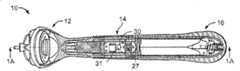
图1为根据一个实施方案的剃刀手柄的顶视图。Figure 1 is a top view of a razor handle according to one embodiment.
图1A和1B为图1的剃刀手柄的横截面图。1A and 1B are cross-sectional views of the razor handle of FIG. 1 .
图2为图1的剃刀手柄的底视图。Figure 2 is a bottom view of the razor handle of Figure 1 .
图3为图1的剃刀手柄的局部分解图。Fig. 3 is a partially exploded view of the razor handle of Fig. 1 .
图4为从剃刀的握管分解的头部管的透视图。Figure 4 is a perspective view of the head tube disassembled from the handle tube of the razor.
图5为握管的侧视图。Figure 5 is a side view of the grip tube.
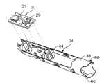
图6为显示其中包含的组件的握管的分解图。Figure 6 is an exploded view of the grip tube showing the components contained therein.
图7至7C为图示说明在握管中包含的组件的装配的分解图。7 to 7C are exploded views illustrating the assembly of the components contained in the grip tube.
图8为握管的透视图,其中LED窗口从管分解,并且致动按钮被省略。图8A为握管的透视图,其中LED窗口被焊接在合适位置,并且致动按钮从管分解。图8B-8D为握管的一部分的放大透视图,其显示致动按钮装配到管上的步骤。Figure 8 is a perspective view of the handle tube with the LED window exploded from the tube and the actuation button omitted. Figure 8A is a perspective view of the handle tube with the LED window welded in place and the actuation button exploded from the tube. 8B-8D are enlarged perspective views of a portion of the grip tube showing the steps of fitting the actuation button to the tube.
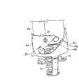
图9是图1的剃刀中所用的卡口组合件的透视图。图9A为图9中的区域A的放大细部图。图9B为卡口组合件的放大细部图,其中公组件和母组件接合,并且卡口弹簧和电池弹簧被压缩。Figure 9 is a perspective view of the bayonet assembly used in the razor of Figure 1 . FIG. 9A is an enlarged detail view of area A in FIG. 9 . 9B is an enlarged detail view of the bayonet assembly with the male and female components engaged and the bayonet spring and battery spring compressed.
图10为图9中所示卡口组合件相对于图9中组合件的位置旋转90°的侧视图。FIG. 10 is a side view of the bayonet assembly shown in FIG. 9 rotated 90° relative to the position of the assembly in FIG. 9 .
图11为卡口组合件下部和容纳下部的电池外壳的分解图。Fig. 11 is an exploded view of the lower portion of the bayonet assembly and the battery case housing the lower portion.
图12为电池外壳的横截面视图。Figure 12 is a cross-sectional view of a battery case.
图13为电池外壳的排气组件的分解图。Figure 13 is an exploded view of the vent assembly of the battery case.
不同附图中类似的参考符号指示类似的元件。Similar reference symbols in different drawings indicate similar elements.
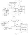
图14A显示具有速度控制开关的剃刀。Figure 14A shows a razor with a speed control switch.
图14B显示具有速度控制开关和用于存储优选速度的存储器的剃刀。Figure 14B shows a razor with a speed control switch and memory for storing preferred speeds.
图14C显示具有间接电源的剃刀。Figure 14C shows a razor with an indirect power supply.
图14D显示用于图14C的间接电源的电压转换器。Figure 14D shows a voltage converter for the indirect power supply of Figure 14C.
图14E显示由控制逻辑和振荡器输出的信号及其对电容器电压的效应。Figure 14E shows the signals output by the control logic and oscillator and their effect on the capacitor voltage.
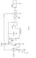
图14F显示用于图14C的间接电源的另一种电压转换器。Figure 14F shows another voltage converter for the indirect power supply of Figure 14C.
图14G显示用于对负载供电的电路。Figure 14G shows the circuit used to power the load.
图15A显示对自刀片更换以来已启动马达的次数进行计数的刀片寿命指示器。Figure 15A shows a blade life indicator counting the number of times the motor has been started since the blade was replaced.
图15B显示对自刀片更换以来马达工作时间进行累积的刀片寿命指示器。Figure 15B shows a blade life indicator accumulating motor operating hours since blade replacement.
图15C显示对自刀片更换以来冲程次数进行计数的刀片寿命指示器。Figure 15C shows a blade life indicator counting the number of strokes since blade replacement.
图15D显示对自刀片更换以来冲程次数进行累积的刀片寿命指示器。Figure 15D shows a blade life indicator accumulating the number of strokes since blade replacement.
图16A显示机械锁。Figure 16A shows a mechanical lock.
图16B显示其中闭锁信号负触发剃刀的锁定电路。Figure 16B shows a lockout circuit in which the lockout signal negatively triggers the shaver.
图17A显示传感马达引出电流变化的测力电路。Figure 17A shows a load cell circuit for sensing changes in motor draw current.
图17B显示传感马达速度变化的测力电路。Figure 17B shows a load cell circuit for sensing motor speed changes.
具体实施方式Detailed ways
总体剃刀结构overall razor structure
参考图1,剃刀手柄10包括剃刀头部12、握管14和电池外壳16。剃刀头部12包括用于在柄部10上安装可更换剃刀片架(未示出)的连接结构,这在剃刀技术领域是熟知的。握管14被构造成能够在剃刮期间由使用者持拿并容纳为剃刀提供电池驱动功能性的剃刀组件,例如印刷电路板和被成形为能够产生振动的马达。握管为一种固定连接头部12从而允许模制制造并提供以下讨论的其它优点的密封单元。参考图3,电池外壳16可拆卸地连接到握管14上,以便使用者能够通过移除电池外壳来更换电池18。电池外壳和握管之间的界面使用例如O形环20密封,从而提供防水装配以保护剃刀内的电池和电子器件。O形环20通常由例如过盈配合安装在握管上的凹槽21内(图5)。再次参考图1,握管14包括致动按钮22,使用者可按压致动按钮以通过电子开关29启动剃刀的电池驱动功能性(图7A)。握管也包括透明窗口24以允许使用者看到灯31或显示装置或其它视觉指示标志(图7A),例如LED或LCD,其为使用者提供电池状态和/或其它信息的视觉指示。灯31通过在握管中的透明窗口下面提供的开45(图8)发出光来。以下更详细地描述剃刀手柄的这些和其它特征。Referring to FIG. 1 , a
模制握管结构Molded Grip Construction
如上所讨论,握管14(细部显示于图4和5中)为与剃刀头部12固定连接的模制组合件。握管的模块性有利地允许以多种不同剃刀头部样式制造单一类型的握管。这继而简化了具有不同头部但电池驱动功能性相同的多种系列产品的制造。除了连接电池外壳的末端开25外,握管是防水的,并且优选为单个一体式部分。因此,保证剃刀手柄10防水性所需的唯一密封是在握管和电池外壳之间由O形环20提供的密封(图3)。这种单一密封构型最大程度地减少了水或水分透过剃刀手柄和损害电子器件的可能性。As discussed above, the handle tube 14 (shown in detail in FIGS. 4 and 5 ) is a molded component that is fixedly attached to the
如图6所示,握管14包含子组件26(也显示于图7C中),其包括振动马达28、印刷电路板30、电子开关29、安装在印刷电路板上的灯31、以及向电子器件提供电池电力的正触点32。这些组件被装配在载体34内,所述载体34还包括电池夹指36和公卡口部分38,其功能将在下文“电池夹”和“电池外壳连接”部分中讨论。剃刀的所有功能电子元件装配到载体34上将允许预先测试电池驱动功能性,以便能够早期检测故障,并使完成剃刀的昂贵刮擦减小到最低限度。子组件26也包括绝缘套管40和安装带42,其功能将在下文“电池夹”部分中讨论。As shown in FIG. 6, the
子组件26如图7-7C所示进行装配。首先将正触点32装配到PCB载体44上,然后将其安装到载体34上(图7)。接着,将印刷电路板30放入PCB载体44中(图7A),将振动马达28安装到载体34(图7B)上,并且将引线46焊接到印刷电路板上从而完成子组件26(图7C)。在装配到握管中之前,可对子组件进行测试。
将子组件26装配到握管中,以便其永久保持在其中。例如,子组件26可包括以过盈配合的方式接合握管内壁中的对应凹槽的突出或臂。The
握管也包括致动按钮22。刚性致动按钮安装到包括以上讨论的窗口24的接纳构件48上(图8)。接纳构件48包括承载致动构件52的悬臂梁50。致动构件52将施加到按钮22的力传递到下面的弹性膜54上(图8)。膜54可以为例如弹性体材料,该材料被模制到握管上,从而不仅形成膜而且也形成弹性体抓握部分。悬臂梁与膜协同作用将提供恢复力,以便在按钮22被使用者按下后返回其正常位置。在按下按钮时,致动构件52接触下面的电子开关29,电子开关启动PCB 30的电路。启动可以是“按下和释放”开/关动作或其他所需动作,例如按开/按关。电子开关29在启动时产生听得见的“喀哒”声,从而给予使用者装置已经正确地接通的反馈。开关优选被成形为需要在短距离施加的较高启动力(例如在约0.25mm位移施加至少4N力)。这种开关布置与按钮22的凹入、低轮廓几何形状结合,趋于防止剃刀在移动期间偶然接通,或者在剃刮期间不经意地关闭。此外,开关/膜/致动构件组合件的结构给使用者提供良好触觉反馈。致动构件52也将按钮22保持在合适位置,致动构件52的中心的孔55接纳按钮22下侧上的突出56(图8B)。The grip tube also includes an
透明窗口24邻近按钮22,使用者可通过窗口观察由下面的灯提供的指示,这将详细描述于下文“电子器件”部分中。Adjacent to the
窗口24和致动按钮装配到握管上示于图8-8D中。首先,通过例如胶粘或超声波或加热焊接(图8)将承载窗口24的接纳构件48密封安装到握管上,以形成以上讨论的一体式防水部分。接着,将按钮22滑到适合位置,并轻轻地(优选用小于10N的力)向下推入到接纳构件中的开口,使突出56与孔55接合(图8A至8C)。The assembly of the
电池外壳连接battery case connection
如上所讨论,电池外壳16可拆卸地连接到握管14上,从而允许移除和更换电池。连接柄部的两个部分。通过卡口连接,在电池的负端和电子元件之间建立电连接。握管承载卡口连接的公接头,而电池外壳承载母接头。图9、9A和10显示装配的卡口连接,其中为了清楚起见,握管和电池外壳已经省略。As discussed above, the
以上讨论的载体34的公卡口接头38提供卡口连接的公接头。公卡口接头38承载一对突出60。这些突出被构造成能被接纳和保持在由电池外壳承载的母卡口组件64的相应狭槽62中。每个狭槽62包括具有成角的壁66、68(图9A)的引入端,以便在电池外壳相对于握管旋转时引导各突出进入相应的狭槽。在每个狭槽62的末端提供定位区域65(图9A)。突出在定位区域65中接合(图9B)使电池外壳牢固、拧进式机械连接到握管上。The
载体34和母卡口组件64均由金属制成,因此突出与狭槽的接合也提供载体和母卡口组件之间的电接触。载体又与装置的电路电接触,而电池的负端与电池弹簧70(图9A)接触,电池弹簧70与母卡口组件电气连通,因此弹簧构件与电元件的接触最终导致在电池和装置的电路之间产生接触。Both the
如图12所示,电池弹簧70安装在弹簧盘72上,所述弹簧盘又固定地安装到电池外壳16的内壁上。母卡口组件64自由在电池外壳16内轴向前后滑动。在其静止位置,母卡口组件通过卡口弹簧74偏压到电池外壳的基座上。卡口弹簧74也安装在弹簧盘72上,因此其上端相对于电池外壳的内壁固定安装。当电池外壳拧到握管上时,公卡口组件上的突出与母卡口组件上的成角狭槽的接合将母卡口组件向前拉,从而压缩卡口弹簧74。卡口弹簧的偏置力促使母卡口组件拖拉公卡口组件,因此将握管拉向电池外壳。因此,柄部的两部分之间的任何间隙由弹簧力封闭,并且O形环受到压缩以提供防水的密封接合。此时接合完全,突出60被接纳在母卡口狭槽62的相应V形定位区域65内(图9B)。这时使用者会察觉到清楚的喀哒声,从而清楚地指示电池外壳已正确接合。这种喀哒声是卡口弹簧的作用使突出快速地滑入V形定位区域65内的结果。As shown in FIG. 12 , the
电池外壳与握管的这种弹力接合将补偿电池外壳和握管间的非线性接缝以及诸如公差之类的其它几何问题。卡口弹簧施加的力也在公卡口组件和母卡口组件之间提供牢固可靠的电接触。This resilient engagement of the battery housing and the grip tube will compensate for non-linear seams between the battery housing and the grip tube as well as other geometrical issues such as tolerances. The force exerted by the bayonet spring also provides a secure and reliable electrical contact between the male and female bayonet assemblies.
在电池外壳被连接及移除时,弹簧支承的母卡口组件也限制作用在公母卡口组件上的力。如果在握管和电池外壳相互接触后使用者继续旋转电池外壳,母卡口组件可在电池外壳内轻微向前移动,从而减少由公卡口组件的突出所施加的力。因此,使力保持相对不变,并且在预定的范围内。这一特征能够防止由于使用者粗力抓握或大部件或组合件公差而导致的部件损坏。The spring-loaded female bayonet assembly also limits the forces acting on the male and female bayonet assemblies when the battery housing is attached and removed. If the user continues to rotate the battery housing after the grip tube and battery housing are in contact with each other, the female bayonet assembly may move forward slightly within the battery housing, thereby reducing the force exerted by the protrusion of the male bayonet assembly. Thus, the force is kept relatively constant and within a predetermined range. This feature prevents component damage due to rough handling by the user or large component or assembly tolerances.
为了完成上述弹力接合,通常重要的是卡口弹簧的弹簧力大于电池弹簧的力。一般来讲,两个弹簧的优选相对力可如下计算:In order to achieve the above-mentioned spring force engagement, it is generally important that the spring force of the bayonet spring is greater than the force of the battery spring. In general, the preferred relative force of the two springs can be calculated as follows:
1.将电池弹簧设计成使得弹簧施加的接触力Fbatmin足以适应最小电池长度。1. Design the battery spring such that the contact force Fbatmin exerted by the spring is sufficient to accommodate the minimum battery length.
2.计算最大电池长度所需的电池弹簧力Fbatmax。2. Calculate the battery spring force Fbatmax required for the maximum battery length.
3.计算紧靠握管来推动电池外壳以克服O形环摩擦力所需的最大力Fpmax。3. Calculate the maximum force Fpmax required to push the battery case against the grip tube to overcome the O-ring friction.
4.确定以封闭状态将电池外壳压靠在握管上所用的最小封闭力Fclmin。4. Determine the minimum closing force Fclmin used to press the battery case against the grip tube in the closed state.
5.根据以下公式计算卡口弹簧施加的力:Fbayonet=FbatmaxFpmax Fclmin。5. Calculate the force exerted by the bayonet spring according to the following formula: Fbayonet=FbatmaxFpmax Fclmin.
例如,在一些实施例中,Fbatmax=4N,Fpmax=2N,并且Fclmin=2N,因此Fbayonet=8N。For example, in some embodiments, Fbatmax=4N, Fpmax=2N, and Fclmin=2N, thus Fbayonet=8N.
电池夹battery clip
如上所讨论,载体34包括一对电池夹指36(图6、10)。这些夹指可充当对电池18施加小夹紧力的两个弹簧(图3)。这种夹紧力应足够强以防止电池靠握管的内壁或其它部件发出喀喀的声响,从而减少使用期间剃刀发出的噪声。优选地,这种夹紧力也应足够强以防止在移除电池外壳和倒置握管时电池掉出。另一方面,这种夹紧力也应足够弱以让使用者能够容易地移除和更换电池。公卡口组件38包括开口区域80(图4),使用者可通过此开口区域将电池拿出。As discussed above, the
大致调节弹簧指及其弹簧力的大小,以允许弹簧指保持以上讨论的最小尺寸电池的重量,防止在垂直持拿剃刀时从中掉出,同时还允许容易地从握管移除最大尺寸的电池。为了满足这些限制,在一些实施方案中,优选在电池和箔之间的摩擦系数为约0.15-0.30下。在装入最小尺寸电池时(例如具有9.5mm直径),一个指的弹簧力为约0.5N,而在装入最大尺寸电池时(例如具有10.5mm直径),一个指的弹簧力小于约2.5N。通常,如果在保持剃刀的电池开口向下时最小尺寸电池不掉出,并且最大尺寸电池能够容易地拿出,则认为弹簧指应发挥了其功能。The size of the spring fingers and their spring force is generally adjusted to allow the spring fingers to hold the weight of the smallest size batteries discussed above, preventing them from falling out when the razor is held vertically, while still allowing the largest size batteries to be easily removed from the grip tube . To meet these constraints, in some embodiments, a coefficient of friction between the cell and foil of about 0.15-0.30 is preferred. The spring force of one finger is about 0.5N when the smallest size battery is loaded (for example, with a diameter of 9.5mm), while the spring force of one finger is less than about 2.5N when the largest size battery is installed (for example, with a diameter of 10.5mm) . Generally, if the smallest size battery does not fall out when holding the battery opening of the razor down, and the largest size battery comes out easily, the spring fingers are considered to be functioning.
参考图6和7C,薄的绝缘套管40(例如塑料箔)还缓冲振动噪声,并且在电池表面损坏时防止短路。如图7C所示,套管40用带42固定到电池夹指上,以便在移出和更换电池时将套管保持在合适位置。绝缘套管所用的适合材料为具有约0.06mm厚度的聚对苯二甲酸乙二醇酯薄膜(PET)。Referring to Figures 6 and 7C, the thin insulating sleeve 40 (eg, plastic foil) also dampens vibration noise and prevents short circuits when the cell surface is damaged. As shown in Figure 7C,
排气电池仓Exhaust battery compartment
在某些条件下,氢会积聚在电池驱动的装置的内部。氢可从电池中释放,或者可通过在电池外电解而产生。这种氢与大气中的氧混合可形成爆炸性气体,该爆炸性气体可潜在地由所述装置的马达或开关产生的火花引爆。因此,应将氢从剃刀手柄排出,同时仍保持防水性。Under certain conditions, hydrogen can accumulate in the interior of battery-operated devices. Hydrogen can be released from the battery, or can be produced by electrolysis outside the battery. This hydrogen mixes with atmospheric oxygen to form an explosive gas that could potentially be detonated by a spark from a motor or switch of the device. Therefore, the hydrogen should be expelled from the razor handle while still maintaining water resistance.
参考图13,在电池外壳16中提供排气孔90。透气但不透液体的微孔膜92焊接到电池外壳16上以覆盖排气孔90。适合的膜材料为聚四氟乙烯(PTFE),可从GOREA商购获得。优选的膜具有约0.2mm的厚度。通常优选的是,膜的防水性为至少70kPa,而透气率在10kPa(100mbar)过压时为至少12L/hr/cm2。Referring to FIG. 13 , a
微孔膜的优点是由膜的两侧上的氢分压差扩散使氢排出。发生排气需要剃刀手柄内的总压不增加。The advantage of the microporous membrane is that the hydrogen is vented by the diffusion of the hydrogen partial pressure difference on both sides of the membrane. Venting requires that the total pressure within the razor handle not increase.
从审美观点看,让使用者看到排气孔和膜是不可取的。此外,如果使膜暴露,就会有膜孔阻塞和/或膜损坏或移除的隐患。为了保护该膜,通过例如胶粘将盖94连接到电池外壳的膜/排气区域上。因此,气体能够从盖94下面逸出,在盖的内表面和电池外壳16的外表面98之间提供开口区域。在附图所示的具体实施中,在邻近排气孔90的电池外壳上提供多个肋96,从而在盖和电池外壳之间产生气槽。然而,如果需要,可用其它结构产生排气间隔,例如盖和/或握管可包括限定单个槽的凹槽,而肋可被省略。From an aesthetic point of view, it is undesirable for the user to see the vent holes and the membrane. Furthermore, if the membrane is left exposed, there is a risk of membrane pore clogging and/or membrane damage or removal. To protect the membrane, a
应选择气槽的高度和宽度以便提供排气的安全度。在一个实例中(未示出),可在排气孔每侧有一个槽。每个槽的高度为0.15mm,而宽度为1.1mm。The height and width of the air groove should be selected to provide a safe degree of exhaust. In one example (not shown), there may be one slot on each side of the vent. Each groove has a height of 0.15 mm and a width of 1.1 mm.
盖94可以为装饰性。例如,盖可携带徽标或其它装饰。盖94也可提供触觉抓握表面或其它符合人机工程学原理的特征。
电子器件electronic device
变速控制variable speed control
通常用电动剃刀来刮剃身体上不同位置处的不同类型的毛发。这些毛发具有明显不同的特性。例如,胡须趋于比腿上的毛更浓密。这些毛发也从皮肤以不同角度伸出。例如,短须大部分垂直于皮肤,而腿毛趋于较平直伸出。Electric razors are commonly used to shave different types of hair at different locations on the body. These hairs have distinctly different properties. For example, whiskers tend to be thicker than the hair on the legs. These hairs also protrude from the skin at different angles. For example, short whiskers are mostly perpendicular to the skin, while leg hair tends to protrude more straightly.
能够容易地剃刮这些毛发部分地取决于刀片架振动的频率。由于这些毛发具有不同的特性,因此不同的振动频率可能适宜于不同类型的毛发。因此,为使用者提供控制此振动频率的方式是有用的。The ease with which these hairs can be shaved depends in part on the frequency at which the cartridge vibrates. Since these hairs have different properties, different vibration frequencies may be suitable for different types of hair. Therefore, it would be useful to provide a way for the user to control this vibration frequency.
如图14A所示,剃刮刀片架的振动频率受到在控制逻辑105控制下具有占空系数的脉冲宽度调制器301的控制。如本文所用,“占空系数”是指脉冲的时间长度与脉冲之间暂停时间长度之比。因此,低占空系数的特征是脉冲时间短,而脉冲之间的等待时间长。高占空系数的特征是脉冲之间的等待时间短。改变占空系数能够改变马达306的速度,这又能控制剃刀片架的振动频率。As shown in FIG. 14A , the vibration frequency of the shaving cartridge is controlled by a
控制逻辑105可在微控制器或其它基于微处理器的系统中执行。控制逻辑也可在专用集成电路(ASIC)或作为现场可编程门阵列(FPGA)执行。
马达306可以是任何致使剃刀片架运动的能耗装置。马达306的一种具体实施包括微型定子和连接到剃刀片架的转子。马达306的另一种具体实施包括连接到剃刀片架的压电装置。或者,马达306可以作为磁性连接到具有振荡磁场的剃刀片架的装置。
在具有变速控制的剃刀中,逻辑控制105从速度控制开关304接收输入速度控制信号302。作为对速度控制信号302的响应,逻辑控制105使脉冲宽度调制器301改变其占空系数。这继而使马达速度改变。因此,可将脉冲宽度调制器301看作速度控制器。In a razor with variable speed control, the
速度控制开关304可以多种方式实施。例如,速度控制开关可连续移动。在这种情况下,使用者可从连续速度中选择。或者,速度控制开关304可具有不连续停止,以便使用者能够从一组预定马达速度中选择。The
速度控制开关304可呈多种形式。例如,开关304可以为连续移动或在不连续步进之间移动的旋钮或滑动器。开关304也可以是一组按钮,每个按钮指定不同的速度。The
或者,开关304可以是一对按钮,指定一个按钮增速,指定另一个按钮减速。或者,开关304可以是单个按钮,按下按钮连续或不连续地在不同速度之间循环。Alternatively, switch 304 may be a pair of buttons, with one button assigned to increase speed and the other button assigned to reduce speed. Alternatively, switch 304 may be a single button that is pressed to cycle between different speeds, either continuously or discontinuously.
另一种类型的开关304是弹簧支承的触发器。此类型的开关让使用者能够连续改变振动频率,同时以能够通过压挤触发器来连续改变链锯速度的方式剃刮。Another type of
也可以通过对控制逻辑105适当编程来按下致动按钮22使其作为速度控制开关304工作。例如,可以对控制逻辑105适当编程,以便将致动按钮22的双按或长按作为改变马达速度的命令。Depressing the
可用速度之一可优化用于对剃刀进行清洁。此速度的一个实例是最高可能振动频率,这一频率可通过使控制逻辑105尽可能高的驱动占空系数来达到。作为另外一种选择,控制逻辑105可以清洁模式操作。在此模式中,使马达306扫描一定范围的振动频率。这使马达306能够模拟与刀片、刀片架及任何污染的碎粒(如剃刮的胡须末)相关的不同机械共振频率。清洁模式可作为一定频率范围的连续扫描执行,或者作为步进扫描,其中控制逻辑105使马达306步进通过数个不连续频率,在每个这种频率有瞬间的暂停。One of the available speeds can be optimized for cleaning the shaver. An example of this speed is the highest possible vibration frequency, which can be achieved by driving the
在一些情况下,使剃刀存储一个或多个优选振动频率是有用的。这可通过提供与控制逻辑105连通的存储器实现,如图14B所示。为了利用这一特性,使用者可利用单独控制,或者按照预定次序按下致动按钮22,选择速度并传递存储信号。在需要时,使用者可再次利用单独控制,或者按照预定次序按下致动按钮22来调用这种被存储的速度。In some cases it is useful to have the razor store one or more preferred vibration frequencies. This can be accomplished by providing memory in communication with the
如图3A-3B所示,剃刀的特征在于具有一种间接转换系统,其中致动按钮22间接通过操作脉冲宽度调制器301的控制逻辑105来控制马达306。因此,与其中开关状态直接存储马达306状态的纯机械转换系统不同,间接转换系统将存储控制逻辑105中马达306的状态。As shown in FIGS. 3A-3B , the razor features an indirect switching system in which the
由于致动按钮22不再需要以机械方式存储马达306的状态,间接转换系统在选择和布置致动按钮22方面提供更大的灵活性。例如,本文所公开的具有间接转换系统的剃刀可以利用结合清晰触觉反馈和较短移动距离的符合人机工程学原理的按钮。以较短距离移动的这种按钮也易于密封不使水分侵入。Since the
间接转换系统的另一个优点是,可对控制逻辑105编程以解释启动模式,并以此模式为基础推断使用者的意图。这在上面讨论控制马达306的速度时已讨论过。然而,也可以编制控制逻辑105的程序以检测及忽略致动按钮22的异常操作。因此,应当忽略异常长时间按下致动按钮22,例如在剃刮时无意按下的情况。这一特征防止出现与偶然关闭马达306相关的问题。Another advantage of the indirect conversion system is that the
电压控制器voltage controller
剃刀的效能将部分地取决于电池316提供的电压。在常规机动湿法剃刀中,存在最佳电压或电压范围。一旦电池电压超出最佳电压范围,就会削弱剃刀的效能。The effectiveness of the razor will depend in part on the voltage provided by the battery 316 . In conventional motorized wet razors, there is an optimum voltage or range of voltages. Once the battery voltage exceeds the optimal voltage range, it will weaken the performance of the shaver.
为了克服这一难题,如图14C所示,剃刀的特征在于具有一种间接电源,该间接电源使电池316的电压与实际通过马达306观察到的电压分离。实际通过马达306观察到的电压受控制逻辑105控制,控制逻辑监测电池电压,并响应电池电压测量来控制最终补偿电池电压变化的各种装置。这将得到通过马达306观察到的基本恒定电压。To overcome this difficulty, the razor features an indirect power source that separates the voltage of the battery 316 from the voltage actually seen by the
对通过马达306观察到的电压进行控制的本文所述方法和系统适用于任何耗能负载。因此,图14C涉及一般性负载306。The methods and systems described herein for controlling the voltage seen by the
在一个实施方案中,将马达306设计成在小于额定电池电压的工作电压下工作。因此,在装入新电池316时,电池电压太高,必须使其降低。降低的幅度随着电池316的消耗而减小,直到最后不再需要降低。In one embodiment, the
通过提供与电池316电气连通的电压监控器312可很容易地降低电压。电压监控器312将测定的电池电压输出到控制逻辑105。响应时,控制逻辑105改变脉冲宽度调制器301的占空系数,以保持通过马达306观察到的恒定电压。例如,如果测定的电池电压为1.5伏,而马达306被设计成在1伏工作,则控制逻辑105应将占空系数比设定为75%。这将得到自脉冲宽度调制器301的输出电压,即平均与马达的工作电压一致。The voltage can be easily reduced by providing a voltage monitor 312 in electrical communication with the battery 316 . The voltage monitor 312 outputs the measured battery voltage to the
在大多数情况下,占空系数为电池电压的非线性函数。在这种情况下,控制逻辑105被配置成用非线性函数计算,或者使用查表来确定正确的占空系数。作为另外一种选择,控制逻辑105可从脉冲宽度调制器301的输出获得电压测量值,并用这一测量值反馈控制输出电压。In most cases, the duty cycle is a nonlinear function of the battery voltage. In this case, the
在另一个实施方案中,将马达306设计成在高于额定电池电压的工作电压工作。在这种情况下,电池电压随着电池316的消耗被增量升压。此第二实施方案的特征在于具有上述电压监控器312与控制逻辑105控制的电压转换器314。以下将详细描述适合的电压转换器314。In another embodiment, the
第三实施方案在一个装置中结合前述两种实施方案。在这种情况下,控制逻辑105通过在测定的电池电压超过马达工作电压时降低输出电压开始。随后,在测量的电池电压低于马达工作电压时,控制逻辑105将占空系数固定并开始控制电压转换器312。A third embodiment combines the two preceding embodiments in one device. In this case, the
在常规电动剃刀中,马达速度随着电池316的消耗而逐渐降低。这种逐渐降低充分警示使用者需要更换电池316。然而,在具有间接电源的电动剃刀中没有这种警示。一旦电池电压低于某种较低阈值,马达速度就会突然降低,甚至在剃刮中间也会出现这种情况。In a conventional electric shaver, the motor speed gradually decreases as the battery 316 is depleted. This gradual decrease is sufficient to alert the user that the battery 316 needs to be replaced. However, there is no such warning in electric razors with indirect power supply. Once the battery voltage drops below some lower threshold, the motor speed suddenly drops, even in the middle of a shave.
为了预防这种不便,以电压监控器312提供的信息为基础,控制逻辑105将低电池电压信号提供到低电池电压指示器414。低电池电压指示器414可以是在电压低于阈值时点亮的单一状态输出装置,例如LED,或者相反,可以是在电压高于阈值时保持点亮而在电压低于此阈值时熄灭的单一状态输出装置。或者,低电池电压指示器414可以是提供图形或数字显示以指示电池316状态的多重状态装置,例如液晶显示器。To prevent this inconvenience,
也可以用电压监控器312与控制逻辑105结合,在电池电压低于深度放电阈值时完全禁用剃刀操作。这一特性减少了由于电池316深度放电使电池渗漏而导致剃刀损坏的可能性。It is also possible to use the voltage monitor 312 in conjunction with the
图14D中所示的适合电压转换器312以控制振荡器的开关S1为特征。此开关连接到致动按钮22上。因此,使用者按下致动按钮22将振荡器接通。振荡器输出连接到晶体管T1的门上,此门在振荡器控制下作为开关。电池316提供电池电压VBAT。A suitable voltage converter 312 shown in FIG. 14D features a switch S1 that controls the oscillator. This switch is connected to the
在晶体管T1处于导电状态时,电流从电池316流过感应器L1,从而将能量储存在感应器L1中。在晶体管处于非导电状态时,通过感应器L1的电流将继续流动,这一次通过二极管D1。这使电荷转移通过二极管D1并进入电容器C1。使用二极管D1将防止电容器C1通过晶体管T1放电接地。通过选择性允许电荷积累进入电容器C1增加其电压,振荡器因此控制跨电容器C1的电压。When transistor T1 is in a conductive state, current flows from battery 316 through inductor L1, thereby storing energy in inductor L1. With the transistor in its non-conducting state, current through inductor L1 will continue to flow, this time through diode D1. This transfers charge through diode D1 and into capacitor C1. Diode D1 is used to prevent capacitor C1 from discharging through transistor T1 to ground. The oscillator thus controls the voltage across capacitor C1 by selectively allowing charge accumulation into capacitor C1 to increase its voltage.
在图14D所示的电路中,振荡器使时变电流存在于感应器L1中。因此,振荡器感应出跨感应器L1的电压。然后使此感应电压加到电池电压,所得总和可跨过电容器C1得到。这在电容器C1产生输出电压,该输出电压大于由电池单独提供的电压。In the circuit shown in Figure 14D, the oscillator causes a time-varying current to exist in inductor L1. Therefore, the oscillator induces a voltage across inductor L1. This induced voltage is then added to the battery voltage and the resulting sum is obtained across capacitor C1. This produces an output voltage at capacitor C1 that is greater than the voltage provided by the battery alone.
基本为电压转换器312的输出电压的电容器电压既连接到控制逻辑105上,又连接到最终驱动马达306的脉冲宽度调制器301上。当电容器电压达到特定阈值时,控制逻辑105输出连接到振荡器的振荡器控制信号“osc_ctr”。控制逻辑105用振荡器控制信号选择性地打开和关闭振荡器,从而响应来自电容器电压本身的反馈来调节电容器电压。这种反馈控制系统的设定点(即跨电容器C1的电压)设定为通过马达306观察到的恒定工作电压。The capacitor voltage, which is substantially the output voltage of the voltage converter 312 , is connected both to the
在振荡器和接地之间设置的电阻器R1作为去耦合电路的一部分将振荡器的控制从开关S1转移到控制逻辑105。在控制逻辑的初始化之前,携带振荡器控制信号的端口(“振荡器控制端口”)设定为高阻抗输入端口。因此,它是控制振荡器工作的开关S1。在这种情况下,电阻器R1防止从振荡器“控制端口”到接地的短路。在初始化后,振荡器控制端口变成低阻抗输出端口。Resistor R1 placed between the oscillator and ground transfers control of the oscillator from switch S1 to control
最后,使用者将完成剃刮,在这种情况下,他可能想要将马达306关闭。在控制逻辑105正在控制振荡器时,不移除电池316将无法关闭剃刀。为了避免这一窘境的发生,定期确定外部开关S1的状态是有用的。通过配置控制逻辑105使振荡器控制端口定期变成高阻抗输入端口以便对跨电阻器R1的电压采样,可达到这一目的。Eventually, the user will finish shaving, in which case he may want to turn the
在某些类型的开关中,开关的状态指示使用者的意向。例如,处于关闭位置的开关S1指示使用者要将马达306接通,而处于打开位置的开关S1指示使用者要将马达306关闭。如果因此采集的电压样品指示使用者已将开关S1打开,则在振荡器控制端口再次成为低阻抗输出端口时,控制逻辑105产生振荡器控制信号以将振荡器关闭,从而也同时关闭马达306。这样一来,控制逻辑105也关闭其自身的电源。In some types of switches, the state of the switch indicates the user's intent. For example, a switch S1 in the off position indicates to the user to turn on the
在其它类型开关中,开关S1的关闭只指示使用者要将马达的状态从开启变成关闭,反之亦然。在使用此开关的实施方案中,在使用者启动开关S1时,跨电阻器R1的电压只短暂地改变。因此,控制逻辑105使跨电阻器R1的电压被足够频繁地采样,以保证捕获使用者对开关S1的瞬间启动。In other types of switches, closing of switch S1 simply indicates to the user that the state of the motor is to be changed from on to off, and vice versa. In an embodiment using this switch, when the user activates switch S1, the voltage across resistor R1 changes only momentarily. Therefore, the
图14E显示振荡器控制信号、振荡器输出和电容器电压之间的相互作用。在电容器电压低于较低阈值时,振荡器控制信号接通,从而将振荡器接通。这使更多电荷积累在电容器C1中,继而提高电容器电压。一旦电容器电压达到较高阈值,振荡器控制信号断开,从而将振荡器断开。由于没有来自电池316的更多电荷在电容器C1中积累,积累的电荷开始渐渐枯竭,因此电容器电压也开始降低。电压继续降低,直到再次达到较低阈值,在此时重复前述周期。Figure 14E shows the interaction between the oscillator control signal, oscillator output and capacitor voltage. When the capacitor voltage is below the lower threshold, the oscillator control signal is turned on, turning the oscillator on. This causes more charge to accumulate in capacitor C1, which in turn increases the capacitor voltage. Once the capacitor voltage reaches the upper threshold, the oscillator control signal is turned off, turning off the oscillator. With no more charge accumulating in capacitor C1 from battery 316, the accumulated charge begins to drain and the capacitor voltage begins to decrease. The voltage continues to decrease until the lower threshold is reached again, at which point the preceding cycle repeats.
图14F所示的电压转换器312的另一个实施方案与图14D相关所述相同,不同的是用一个具有由RC电路(R2和C2)控制的门的附加晶体管T2代替二极管D1。在此实施方案中,当振荡器不起作用时,附加晶体管T2的发射极和基极之间的电压(VBE2)为零。因此,通过附加晶体管T2的电流断开。这意味着没有电荷提供到电容器C1来补充从电容器C1排出的电荷。当振荡器起作用且振荡器频率大于RC电路的断开频率时,发射极和基极之间的电压(VBE2)约为电池电压VBAT的一半。因此,附加晶体管T2作为二极管使电流通到电容器C1,同时防止电容器C1放电接地。Another embodiment of voltage converter 312 shown in FIG. 14F is the same as described in relation to FIG. 14D except that diode D1 is replaced by an additional transistor T2 having a gate controlled by an RC circuit (R2 and C2). In this embodiment, the voltage (VBE2 ) between the emitter and base of the additional transistor T2 is zero when the oscillator is inactive. Therefore, the current through the additional transistor T2 is switched off. This means that no charge is provided to capacitor C1 to replenish the charge drained from capacitor C1. When the oscillator is active and the oscillator frequency is greater than the break frequency of the RC circuit, the voltage between the emitter and base (VBE2 ) is approximately half the battery voltage VBAT . Thus, the additional transistor T2 acts as a diode to pass current to capacitor C1 while preventing capacitor C1 from discharging to ground.
图14F所示电路的另一个显著特点是,脉冲宽度调制器301用直接来自电池316的电压供电。因此,脉冲宽度调制器301的输出电压可能不高于电池电压。因此,在图14F中,马达306通过降压供电,而用升压(跨电容器C1的电压)对控制逻辑105供电。然而,图14F所示的电路也可显示从跨电容器C1的电压提取输入的脉冲宽度调制器316的特征(如图14D所示)。Another notable feature of the circuit shown in FIG. 14F is that the
图14G更详细地显示驱动图14F所示类型的电压转换器312的电路。其中更详细地显示振荡器与控制逻辑105关联的连接。然而,图14G所示的电路在其它方面与关于图14D所述基本相同,修改如图14F所示。Figure 14G shows in more detail the circuitry to drive a voltage converter 312 of the type shown in Figure 14F. The connection of the oscillator associated with the
如本文所述,电压控制系统为马达306提供恒定工作电压。然而,电动剃刀可包括马达以外的负载。任何或所有这些负载可同样得益于本文公开的电压控制系统提供的恒定工作电压。As described herein, the voltage control system provides a constant operating voltage to the
可得益于恒定工作电压的一种负载为控制逻辑105本身。可商购获得的逻辑电路105一般设计成在高于常规电池1.5伏电压工作。因此,将升压提供到控制逻辑的电压控制系统避免需要额外电池。One load that may benefit from a constant operating voltage is the
刀片架寿命检测Blade holder life detection
在每日切断数百根胡须的过程中,剃刀片架的刀片不可避免地变钝。变钝难以通过视觉观察发现。通常,钝刀片只在太晚时才被发觉。在太多情况下,当使用者认识到刀片钝得不能再使用时,他已经体会到令人不愉快的剃刮经历。In the process of cutting off hundreds of hairs every day, the blades of the razor cartridge inevitably become dull. Dullness is difficult to detect by visual inspection. Often, dull blades are only noticed when it's too late. In too many cases, a user has experienced an unpleasant shaving experience when he realizes that the blade is too blunt to be used any longer.
用钝刀片进行的最后剃刮属于用剃刀剃刮的更不愉快方面。然而如果剃刀片架太昂贵,就可以理解为什么大多数使用者不太情愿过早更换刀片架。A final shave with a blunt blade is among the more unpleasant aspects of shaving with a razor. However, if the razor cartridges are too expensive, it is understandable why most users are reluctant to replace the cartridges prematurely.
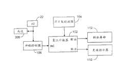
为了帮助使用者确定何时需要更换刀片架,剃刀包括图15A所示具有计数器102的刀片寿命指示器100,该计数器保持指示刀片使用程度的计数。计数器与柄部10上的致动按钮22和在剃刀头部12的远端安装的刀片架检测器104连通。合适的计数器102可在控制逻辑105中执行。To assist the user in determining when the cartridge needs to be replaced, the razor includes a
刀片架检测器104可以多种方式实施。例如,刀片架检测器104可包括被成形为能够接合刀片架上相应触点的触点。
剃刀片架可包括一片、二片或多于两片的刀片。在整个说明书中,所指的是单一刀片。然而应当理解,此刀片可以是刀片架中的任何刀片,而且所有刀片都会磨损。Razor cartridges may include one, two, or more than two blades. Throughout the description, reference is made to a single blade. It should be understood, however, that the blade can be any blade in the cartridge, and that all blades will wear.
在操作中,在使用者更换刀片架时,刀片架检测器104向计数器102发送复位信号。作为另外一种选择,复位信号可手动产生。例如,使用者按下复位按钮,或者使用者以预定模式按下致动按钮。这种复位信号使计数器102重置其计数。In operation, the
可将检测刀片架的能力用于重置计数以外的应用。例如,可用刀片架检测器104确定是否使用了正确的刀片架,或者刀片架是否未以正确的方式插入。在连接到控制逻辑105时,刀片架检测器104可致使马达被禁用,直到所述状况被纠正。The ability to detect cartridges can be used for applications other than reset counting. For example, the
当使用者剃刮时,计数器102改变计数状态以反映刀片的额外磨损。计数器102改变计数状态可以有多种方式。As the user shaves, the
在图15A所示的实施方案中,计数器102每当马达接通就递增改变计数。对每次剃刮时间改变很小的使用者而言,这能合理准确地估计刀片的使用。In the embodiment shown in Figure 15A, the
在一些情况下,马达已接通的次数可能使刀片的剩余寿命错估。例如,在一个人“借”自己的剃刀去剃刮自己的腿时会出现此类错误。这导致只用一次启动马达去剃刮相当大的面积。In some cases, the number of times the motor has been turned on may miscalculate the remaining life of the blade. This error occurs, for example, when a person "borrows" his own razor to shave his own legs. This results in shaving a relatively large area with only one activation of the motor.
在图15B所示的一个可供选择的实施方案中,前述难题得到了克服,其中致动按钮22和计数器102与定时器106连通。在这种情况下,致动按钮22将信号发送到控制逻辑105和定时器106。因此,计数器102保持计数指示从上一次刀片架更换以来的累积马达工作次数。The foregoing difficulties are overcome in an alternative embodiment shown in FIG. In this case, actuating
累积马达工作次数提供刀片磨损的改良指示器。然而,通常刀片并非在马达工作的所有时间接触皮肤。因此,基于马达工作时间的评估不能帮助而是会高估刀片磨损。此外,马达开关可能会非有意接通,例如当在行李中剃刀受到推挤时。在这些情况下,不仅电池消耗,而且计数器102也会指示刀片磨损,即使刀片未遇到一根胡须。Cumulative motor duty cycles provide an improved indicator of blade wear. However, usually the blades are not in contact with the skin all the time the motor is operating. Therefore, an assessment based on motor operating hours does not help but overestimates blade wear. Furthermore, the motor switch can be switched on unintentionally, for example if the shaver is jostled in luggage. In these cases, not only is the battery drained, but the
图15C所示的另一个实施方案包括与冲程检测器108连通的计数器102。在这种情况下,致动按钮22向冲程检测器108和控制逻辑105二者发送信号。因此,接通马达也就接通了冲程检测器108。Another embodiment shown in FIG. 15C includes a
冲程检测器108检测刀片与皮肤之间的接触,并在检测到这种接触时向计数器102发送信号。以此方式,冲程检测器108为计数器102提供刀片实际使用的指示。在图15C的实施方案中,计数器102保持计数指示从上一次刀片架更换以来刀片经历的累积冲程数。因此,计数器102会忽略马达运行但刀片未实际使用的时段。The
多种实施方案可用于冲程检测器108。一些实施方案依赖皮肤上或附近的电性质和自由间隔中电性质之间的变化。例如,通过测量与皮肤接触相关的电阻、感应系数或电容变化,冲程检测器108可检测到皮肤接触。其它实施方案依赖皮肤上刀片振动的声学标记与在自由间隔中刀片振动的声学标记的差异。在这些具体实施中,冲程检测器108包括连接到信号处理装置的麦克风,信号处理装置被成形为能够区分这两种标记。另一个具体实施依赖刀片接触皮肤时马达工作特性的变化。例如,由于与皮肤接触相关负载增加,马达对电流的需求增加,而马达的速度可能降低。这些具体实施包括电表或其它电流指示装置和/或速度传感器。Various implementations are available for
然而,依赖冲程数的估计可能不准确,因为并非所有冲程都具有相同长度。例如,在腿上的冲程可能比剃须所需的数个冲程更磨损刀片。然而,冲程检测器108并不能辨别不同长度冲程之间的差别。However, estimates that rely on the number of strokes can be inaccurate because not all strokes are of the same length. For example, a stroke on the leg may wear the blade more than the several strokes required for shaving. However, the
图15D所示的另一个具体实施包括与致动按钮22和定时器106连通的冲程检测器108。定时器106与计数器102连通。同样,致动按钮向冲程检测器108和控制逻辑105二者发送信号。冲程检测器108分别响应检测冲程的开始和结束中止和启动定时器106。此实施方案与图15C相同,不同的是计数器102现在保持计数指示从上一次刀片架更换以来刀片架与皮肤接触的累积次数(称为“冲程次数”)。Another implementation shown in FIG. 15D includes a
如图15D相关所述冲程检测器108与定时器106结合用于提供指示刀片磨损信息以外的应用。例如,马达长期工作不存在冲程可能指示马达已经接通或不经意地接通。当剃刀在行李中受到推挤时可能会发生这种情况。或者,在剃刮后心不在焉地忽略关闭马达也会出现这种情况。The
在图1A-1D所示的实施方案中,计数器102与更换指示器110连通。在计数达到指示刀片不能再用的状态时,计数器102向更换指示器110发送更换信号。响应时,更换指示器110向使用者提供视觉、听觉或触觉暗示,指示刀片不能再用。示例性暗示可由LED、蜂鸣器或改变马达速度或换句话讲将不合常规的情况(例如突突的声响)引入马达操作的控制器提供。In the embodiment shown in FIGS. 1A-1D ,
计数器102包括任选的提供剩余寿命信号的剩余寿命输出,指示刀片的剩余寿命估计值。剩余寿命估计值通过比较计数与预期寿命来获得。剩余寿命信号提供给剩余寿命指示器112。合适的剩余寿命指示器112是一种低功率显示器,其显示磨损信号启动磨损指示器之前剩余的预期剃刮次数。作为另外一种选择,剩余寿命估计值可由图形显示。例如,以指示剩余寿命估计值的频次闪光,或者根据预定模型选择性使数个LED发光。
旅行锁travel lock
在某些情况下,可能会不经意地接通电动湿剃刀的马达。例如,在旅行中化妆套件中的其它物品移动和按压致动按钮22时可能发生这种情况。如果发生这种情况,马达就会消耗电池,直到电池耗尽。In some cases, the wet electric shaver's motor may be switched on inadvertently. This can happen, for example, when other items in the toiletry kit are moved and the
为避免这一问题,剃刀可包括锁。一种锁为致动按钮22自身上的机械锁200。机械锁200的一个实例为图16A所示的滑盖。在剃刀储存备用时,滑盖将致动按钮22盖上。机械锁的其它实例与剃刀座架相关而不是与剃刀本身相关。例如,开关可被成形为在剃刀放入座架中时将致动按钮22盖上。To avoid this problem, the razor can include a lock. One type of lock is a
其它锁为电子工具。电子锁的一个实例为如图16B所示的锁定电路202,该电路从致动按钮22接收开关信号204(在附图中被标为“1/0”),并从触发电路208接收触发信号206(在附图中被标为“触发信号源”)。锁定电路202响应开关信号204和触发信号206的状态将马达控制信号210输出到控制逻辑105。Other locks are electronic tools. An example of an electronic lock is a
所述触发电路208用触发信号206使锁定电路202触发和负触发。如本文所用,在按下致动按钮22启动和中止马达时认为锁定电路202触发。在按下致动按钮22根本不能操作马达时认为锁定电路202负触发。The
触发电路208和锁定电路202一般包括数字逻辑电路,数字逻辑电路响应其各自输入状态的变化改变其各自的输出状态。因此,它们便于在控制逻辑105内执行。然而,虽然数字逻辑元件提供建立此电路的方便方式,但都不排除用模拟或机械组件发挥类似作用。以下描述触发电路208或其部分的实例。
触发电路208的一个实例包括触发开关。在此实施方案中,使用者操作触发开关改变触发信号206的状态。使用者随后按下致动按钮22将马达启动。剃刮后,使用者再次按下致动按钮22,此次使马达停止。随后操作触发开关使锁定电路202负触发。One example of
作为另外一种选择,触发电路208可被成形为在检测到马达已断开时使锁定电路自动负触发。在这种情况下,触发电路208一般应包括输入,以接收指示马达已断开的信号。Alternatively,
如本文所用,“开关”包括按钮、控制杆、滑动器、衬垫以及用于实现逻辑信号状态变化的它们的组合。开关不必由物理接触启动,而是由携带的辐射能(例如光能或声能)启动。开关可由使用者直接操作。此开关的一个实例为致动按钮22。作为另外一种选择,开关可通过改变剃刀的配置进行操作,例如在其座架内更换剃刀,或者移除和安装刀片架。As used herein, "switch" includes buttons, levers, sliders, pads, and combinations thereof for effecting a change of state of a logic signal. The switch is not necessarily activated by physical contact, but by carried radiant energy such as light or sound energy. The switch can be directly operated by the user. One example of such a switch is the
如图16B所示,可将锁定电路202抽象地视为“与”门。虽然锁定电路能够作为“与”门执行,但也可用具有适合真值表的任何数字逻辑电路完成锁定电路202的触发功能。例如,可通过触发开关与致动按钮22串联执行锁定电路202。As shown in FIG. 16B , the
在另一个实施方案中,触发电路208包括定时器。定时器的输出致使触发电路208开始使锁定电路202触发。在预定剃刮时间过后,定时器让触发电路208使锁定电路202负触发,从而关闭马达。剃刮时间的长度相应于一般剃刮时间。合适长度在约5和7分钟之间。In another embodiment,
在此实施方案中,在按下致动按钮22时马达运转,直到再次按下致动按钮22,或者直到剃刮时间结束。要是使用者比剃刮时段花更长时间剃刮,马达就会关闭。在这种情况下,使用者必须再次按下致动按钮22以重新启动马达并完成剃刮。为避免这种情况的发生,触发电路208可具有响应使用者“延长”的请求延长预置剃刮时间的适应性反馈回路。In this embodiment, the motor runs when the
在触发电路208包括定时器时,定时器上的复位输入连接到锁定电路202的输出上或连接到致动按钮22上。这使定时器能够响应开关信号204状态的变化自身复位。具体地讲,只要开关信号204将马达关闭,定时器就会自身复位。当使用者在剃刮时间结束之前或在剃刮时间结束时按下致动按钮22时,可能发生这种情况。When the
在另一个具体实施中,触发电路208包括具有输入的解码器,所述输入连接到致动按钮22上或单独的解码器输入按钮上。在这种情况下,取决于解码器输出的触发信号206的状态由使用者手动控制,可根据预定模式按下致动按钮22,或者在可供选择的实施方案中操作解码器输入按钮。In another implementation, the
例如,在解码器从致动按钮22提取输入的情况下,可编制解码器程序,以便通过改变触发信号206的状态来响应延长按压致动按钮22或快速双按致动按钮22。作为另外一种选择,在解码器从单独的解码器输入开关接受输入的情况下,使用者只需要操作解码器输入开关。使用者不需要记住如何用致动按钮22来锁定和结锁马达。For example, where the decoder takes input from the
在依赖使用者改变触发信号206状态的那些具体实施中,提供指示器如LED是有用的,所述指示器可为使用者提供是否他已成功地改变触发信号206的状态的反馈。In those implementations that rely on the user to change the state of the
在其他具体实施中,触发电路208依赖剃刀的配置确定是否应使锁定电路202负触发。例如,触发电路208可包括检测剃刀片架安装和移除的接触开关。在移除刀片架时,触发电路208使锁定电路202负触发。作为另外一种选择,触发电路208可包括检测是否剃刀被放在座架中的接触开关。在这种情况下,在触发电路208检测到剃刀被放在剃刀座架中时,使锁定电路202负触发。In other implementations, the
在触发电路208响应刀片架存在的情况下,使用者可通过从柄部移除刀片架来防止马达意外接通。为了正常操作剃刀,使用者要重新将刀片架安装在柄部上。With the
在触发电路208响应座架存在的情况下,使用者可通过将其放在座架中来防止马达意外接通。在剃刀正常工作时,使用者将其从座架上拿下,这是他在任何情况下都要做的事儿。With the
虽然本文所述的实施方案控制马达操作,但可用所公开的方法和装置防止电池不经意因负载耗能。While the embodiments described herein control motor operation, the disclosed methods and apparatus can be used to prevent inadvertent load draining of the battery.
剃刮力测量Shaving force measurement
在剃刮过程中,使用者要用一定的力将刀片按在皮肤上。剃刮力的大小影响剃刮的质量。剃刮力太小可能不足以使胡须进入最佳切断位置。剃刮力太大可能使皮肤受到过度摩擦。由于脸轮廓的变化,使用者可能难以保持更恒定的剃刮力,更难以保持最佳的剃刮力。During the shaving process, the user will press the blade against the skin with a certain force. The size of the shaving force affects the quality of the shave. Too little shaving force may not be enough to get the beard into the best cutting position. Shaving too aggressively may subject the skin to excessive friction. Due to the changing contours of the face, it may be difficult for the user to maintain a more constant shaving power, even more difficult to maintain an optimal shave.
这一难题可用一种剃刀来克服,该剃刀包括图4A和4B所示的测力电路400。所示的测力电路400利用这样一种事实:在电动剃刀中,剃刮力将部分地决定施加到驱动刀片的马达306的负载。因此,该马达306的工作特性响应剃刮力而发生变化。This difficulty can be overcome with a razor that includes the
图17A所示的测力电路400利用响应不同负载的马达306引出的电流变化。在剃刮力增加时,马达306作为响应引出更大电流。因此,图17A中具体实施的特点是具有电流传感器402,该传感器感应马达306引出的电流的大小。电流传感器将力信号408提供给控制逻辑105。The
图17B所示的测力电路利用马达306不同负载产生的马达速度的变化。在剃刮力增加时,马达速度降低。图17B所示实施方案的特点是具有感应马达速度的速度传感器410。该速度传感器将力信号408提供给控制逻辑105。The load-measuring circuit shown in FIG. 17B utilizes the variation in motor speed due to different loads on the
控制逻辑105接收力信号408,并将此信号与指定力信号进行比较,指示在已知负载下这种力信号属于什么力。典型地,选择已知负载对应于剃刀在自由间隔中不与任何表面接触的振动。作为另外一种选择,控制逻辑105将力信号408与一对名义力信号比较,名义力信号相当于剃刀在两种已知负载下振动,一种相应于最小剃刮力,另一种相当于最大剃刮力。The
控制逻辑105然后确定是否所施加的剃刮力超出剃刮力上下限限定的范围。如果施加的剃刮力超出此范围,则控制逻辑105将校正信号412发送到指示器414。指示器414然后将校正信号412转换成由于可视、可听或提供某些触觉刺激而由使用者察觉的可观察信号。The
对于可观察声学信号,指示器414可以是向使用者提供听觉信号的扬声器。对于可观察视觉信号,指示器414可以是向使用者提供可见信号的LED。对于可观察触觉信号,马达306可自身用作指示器414。在检测到不合适的剃刮力时,控制逻辑105将校正信号412发送给马达306,以便使干扰转入正常操作。例如,控制逻辑105可发送校正信号412使马达306发出突突的声响。For observable acoustic signals,
在所有前述情况下,剃刮力不足的信号可以不同于剃刮力过大的信号,因此使用者知道如何校正所施加的剃刮力。In all the foregoing cases, the signal of insufficient shaving force can be different from the signal of too much shaving force, so that the user knows how to correct the applied shaving force.
现在已描述了本发明的一些实施方案。但是应当理解,在不背离本发明精神和范围的条件下可以进行各种修改。Some embodiments of the invention have now been described. It should be understood, however, that various modifications may be made without departing from the spirit and scope of the invention.
例如,虽然上述剃刀包括振动马达并提供振动功能性,但也可提供其它类型电池驱动功能性,例如加热。For example, while the razor described above includes a vibrating motor and provides vibrating functionality, other types of battery-operated functionality may also be provided, such as heating.
此外,虽然在上述实施方案中,将包含窗口的接纳构件焊接到握管中的开口上,但如果需要,也可将窗口模制到握管上,例如将透明膜模制到握管上。Furthermore, while in the embodiments described above the receiving member containing the window is welded to the opening in the handle tube, the window could also be molded to the handle tube, eg a transparent film, if desired.
在一些实施方案中,可使用其它类型的电池外壳连接。例如,可使电池外壳和握管的公接头和母接头对换,使电池外壳携带公接头,而握管携带母接头。又如,可使用提交于2005年4月27日的共同未决美国专利11/115,885所述的方法将电池外壳安装在握管上,所述专利的全部公开内容均以引用的方式并入本文。在一些实施方案中可使用其它安装技术,例如由按钮或其它致动器释放的闩锁系统。In some embodiments, other types of battery housing connections may be used. For example, the male and female connectors of the battery housing and handle can be reversed so that the battery housing carries the male connector and the handle carries the female connector. As another example, the battery housing can be mounted on the grip tube using the method described in co-pending US Patent 11/115,885, filed April 27, 2005, the entire disclosure of which is incorporated herein by reference. Other mounting techniques may be used in some embodiments, such as a latch system released by a button or other actuator.
此外,在一些具体实施中,剃刀可以是一次性的。在这种情况下,可将电池外壳永久性地焊接到握管上,因为没有必要或不需要消费者拿取电池。在一次性的实施方案中,刀片单元也固定地安装到剃刀头部上,而不是作为可拆卸刀片架提供。Additionally, in some implementations, the razor can be disposable. In this case, the battery housing can be permanently welded to the grip tube since there is no need or need for the consumer to access the battery. In a disposable embodiment, the blade unit is also fixedly mounted to the razor head rather than being provided as a removable cartridge.
也可以使用其它排气技术,例如,利用密封阀构件而不是微孔膜的排气系统。此类排气系统描述于例如2005年4月27日提交的美国专利11/115,931中,其全部公开内容以引用的方式并入本文。Other venting techniques may also be used, for example, venting systems utilizing sealed valve members rather than microporous membranes. Such exhaust systems are described, for example, in US Patent 11/115,931, filed April 27, 2005, the entire disclosure of which is incorporated herein by reference.
一些实施方案包括一些上述元件,但不包括本文讨论的一些或所有电子元件。例如,在某些情况下,可用机械开关代替电子开关,并且可省略印刷电路板。Some embodiments include some of the aforementioned elements, but not some or all of the electronic elements discussed herein. For example, in some cases mechanical switches may be substituted for electronic switches and printed circuit boards may be omitted.
因此,其它实施方案在以下权利要求的范围之内。Accordingly, other implementations are within the scope of the following claims.
虽然已对本发明的许多实施方案进行了描述,但是应当理解,在不背离本发明精神和范围的条件下可以进行各种修改。While a number of embodiments of the invention have been described, it will be understood that various modifications may be made without departing from the spirit and scope of the invention.
例如,虽然上述剃刀包括振动马达并提供振动功能性,但也可提供其它类型电池驱动功能性,例如加热。For example, while the razor described above includes a vibrating motor and provides vibrating functionality, other types of battery-operated functionality may also be provided, such as heating.
此外,虽然在上述实施方案中,将包含窗口的接纳构件焊接到握管中的开口上,但如果需要,也可将窗口模制到握管上,例如将透明膜模制到握管上。Furthermore, while in the embodiments described above the receiving member containing the window is welded to the opening in the handle tube, the window could also be molded to the handle tube, eg a transparent film, if desired.
在一些实施方案中,可使用其它类型的电池外壳连接。例如,可使电池外壳和握管的公接头和母接头对换,使电池外壳携带公接头,而握管携带母接头。又如,可使用提交于2005年4月27日的共同未决美国专利11/115,885所述的方法将电池外壳安装在握管上,所述专利的全部公开内容均以引用的方式并入本文。在一些实施方案中可使用其它安装技术,例如由按钮或其它致动器释放的闩锁系统。In some embodiments, other types of battery housing connections may be used. For example, the male and female connectors of the battery housing and handle can be reversed so that the battery housing carries the male connector and the handle carries the female connector. As another example, the battery housing can be mounted on the grip tube using the method described in co-pending US Patent 11/115,885, filed April 27, 2005, the entire disclosure of which is incorporated herein by reference. Other mounting techniques may be used in some embodiments, such as a latch system released by a button or other actuator.
此外,在一些具体实施中,剃刀可以是一次性的。在这种情况下,可将电池外壳永久性地焊接到握管上,因为没有必要或不需要消费者拿取电池。在一次性的实施方案中,刀片单元也固定地安装到剃刀头部上,而不是作为可拆卸刀片架提供。Additionally, in some implementations, the razor can be disposable. In this case, the battery housing can be permanently welded to the grip tube since there is no need or need for the consumer to access the battery. In a disposable embodiment, the blade unit is also fixedly mounted to the razor head rather than being provided as a removable cartridge.
也可以使用其它排气技术,例如,利用密封阀构件而不是微孔膜的排气系统。此类排气系统描述于例如2005年4月27日提交的美国专利11/115,931中,其全部公开内容以引用的方式并入本文。Other venting techniques may also be used, for example, venting systems utilizing sealed valve members rather than microporous membranes. Such exhaust systems are described, for example, in US Patent 11/115,931, filed April 27, 2005, the entire disclosure of which is incorporated herein by reference.
一些实施方案包括一些上述元件,但不包括本文讨论的一些或所有电子元件。例如,在某些情况下,可用机械开关代替电子开关,并且可省略印刷电路板。Some embodiments include some of the aforementioned elements, but not some or all of the electronic elements discussed herein. For example, in some cases mechanical switches may be substituted for electronic switches and printed circuit boards may be omitted.
因此,其它实施方案在以下权利要求的范围之内。Accordingly, other implementations are within the scope of the following claims.
Claims (10)
Translated fromChineseApplications Claiming Priority (2)
| Application Number | Priority Date | Filing Date | Title |
|---|---|---|---|
| US11/220,008 | 2005-09-06 | ||
| US11/220,008US20070050995A1 (en) | 2005-09-06 | 2005-09-06 | Razors |
Related Child Applications (1)
| Application Number | Title | Priority Date | Filing Date |
|---|---|---|---|
| CN2011100493147ADivisionCN102126225A (en) | 2005-09-06 | 2006-09-02 | Razors |
Publications (1)
| Publication Number | Publication Date |
|---|---|
| CN101258004Atrue CN101258004A (en) | 2008-09-03 |
Family
ID=37575207
Family Applications (2)
| Application Number | Title | Priority Date | Filing Date |
|---|---|---|---|
| CN2011100493147APendingCN102126225A (en) | 2005-09-06 | 2006-09-02 | Razors |
| CNA2006800325933APendingCN101258004A (en) | 2005-09-06 | 2006-09-02 | razor |
Family Applications Before (1)
| Application Number | Title | Priority Date | Filing Date |
|---|---|---|---|
| CN2011100493147APendingCN102126225A (en) | 2005-09-06 | 2006-09-02 | Razors |
Country Status (11)
| Country | Link |
|---|---|
| US (6) | US20070050995A1 (en) |
| EP (1) | EP1922186A1 (en) |
| JP (1) | JP2009506822A (en) |
| KR (1) | KR20080035029A (en) |
| CN (2) | CN102126225A (en) |
| BR (1) | BRPI0615621A2 (en) |
| CA (3) | CA2743349A1 (en) |
| MX (1) | MX2008003096A (en) |
| RU (1) | RU2404044C2 (en) |
| TW (1) | TW200726609A (en) |
| WO (1) | WO2007029161A1 (en) |
Cited By (4)
| Publication number | Priority date | Publication date | Assignee | Title |
|---|---|---|---|---|
| CN102365041A (en)* | 2009-04-04 | 2012-02-29 | 博朗公司 | Body grooming device |
| WO2014067118A1 (en)* | 2012-11-01 | 2014-05-08 | The Gillette Company | Battery operated razor |
| CN103950047A (en)* | 2014-04-29 | 2014-07-30 | 任向荣 | Shaver and shaver assembling method |
| CN109744871A (en)* | 2018-12-26 | 2019-05-14 | 乔越 | Insulating pot and its control method |
Families Citing this family (54)
| Publication number | Priority date | Publication date | Assignee | Title |
|---|---|---|---|---|
| US20060059696A1 (en)* | 2004-09-17 | 2006-03-23 | Andis Company | Controller for hand-held electrical device for cutting hair |
| US7694419B2 (en) | 2005-04-27 | 2010-04-13 | The Gillette Company | Battery-operated appliances |
| US20070050995A1 (en)* | 2005-09-06 | 2007-03-08 | Fred Schnak | Razors |
| US8061041B2 (en)* | 2007-02-14 | 2011-11-22 | The Gillette Company | Safety razor |
| CN101965252A (en)* | 2008-02-27 | 2011-02-02 | 美国安全剃刀公司 | Shaving system |
| EP2095915A1 (en)* | 2008-02-29 | 2009-09-02 | Koninklijke Philips Electronics N.V. | Razor |
| FR2932717B1 (en)* | 2008-06-24 | 2011-03-25 | Dubuit Mach | PRINTING MACHINE. |
| EP2307188B2 (en)* | 2008-07-18 | 2018-09-12 | BIC-Violex S.A. | Process for manufacturing a safety razor cartridge, and safety razor cartridge |
| US8151468B2 (en)* | 2008-09-26 | 2012-04-10 | The Gillette Company | Handle for shaving razors having improved grip |
| US8209868B2 (en)* | 2009-07-27 | 2012-07-03 | The Gillette Company | Device with an illuminated button assembly |
| US8510956B2 (en)* | 2010-03-12 | 2013-08-20 | The Gillette Company | Combination shaving and trimming device |
| US8561300B2 (en)* | 2010-06-16 | 2013-10-22 | The Gillette Company | Combination shaving and trimming device |
| RU2457938C1 (en)* | 2011-02-24 | 2012-08-10 | Павел Владимирович Лобко | Razor |
| US20120279075A1 (en)* | 2011-05-02 | 2012-11-08 | Amsel Klaus Guenter | Improved battery housing for battery-powered device |
| US8261450B1 (en) | 2011-11-15 | 2012-09-11 | Dana Charles Cook | Razor and auxiliary handle |
| US20130255455A1 (en)* | 2012-03-29 | 2013-10-03 | Geoffrey McCue | Hair cutting apparatus and method of use |
| KR20160029746A (en) | 2013-05-17 | 2016-03-15 | 하이브리드 레이저 리미티드 | Shaving apparatus |
| US10350771B2 (en)* | 2014-02-18 | 2019-07-16 | Hybrid Razor Ltd | Shaving apparatus |
| USD753401S1 (en)* | 2014-09-09 | 2016-04-12 | The Gillette Company | Toothbrush |
| EP3157311B1 (en)* | 2015-10-15 | 2018-11-28 | The Gillette Company LLC | Method of assembling an electronic subassembly for a personal care product |
| USD794871S1 (en) | 2016-01-15 | 2017-08-15 | Medline Industries, Inc. | Clipper |
| USD795497S1 (en) | 2016-01-15 | 2017-08-22 | Medline Industries, Inc. | Clipper |
| USD765912S1 (en) | 2016-03-23 | 2016-09-06 | Phan Thi Minh Vinh | Razor handle |
| USD802215S1 (en) | 2016-06-10 | 2017-11-07 | Medline Industries, Inc. | Clipper head |
| USD802214S1 (en) | 2016-06-10 | 2017-11-07 | Medline Industries, Inc. | Clipper head |
| USD802216S1 (en) | 2016-06-10 | 2017-11-07 | Medline Industries, Inc. | Clipper head |
| USD802217S1 (en) | 2016-06-10 | 2017-11-07 | Medline Industries, Inc. | Clipper head |
| US10652956B2 (en) | 2016-06-22 | 2020-05-12 | The Gillette Company Llc | Personal consumer product with thermal control circuitry and methods thereof |
| USD818643S1 (en)* | 2016-07-13 | 2018-05-22 | Edgewell Personal Care Brands, Llc. | Razor Actuator Button |
| EP3548231B1 (en)* | 2016-12-01 | 2021-01-20 | Koninklijke Philips N.V. | Hair cutting apparatus comprising a current detector |
| EP3351358B1 (en) | 2017-01-20 | 2019-11-20 | The Gillette Company LLC | Heating delivery element for a shaving razor |
| USD802842S1 (en) | 2017-03-15 | 2017-11-14 | Vu Phan Quang Ngo | Safety razor handle |
| CN110662637B (en)* | 2017-06-29 | 2023-02-28 | 比克维奥莱克斯公司 | Shaver and method for detecting shaving characteristics |
| USD815776S1 (en) | 2017-10-08 | 2018-04-17 | Vu Phan Quang Ngo | Safety razor |
| AT520855B1 (en)* | 2018-01-19 | 2020-01-15 | Jandejsek Thomas | shaver |
| EP3546156B1 (en) | 2018-03-30 | 2021-03-10 | The Gillette Company LLC | Razor handle with a pivoting portion |
| EP3774215B1 (en) | 2018-03-30 | 2024-03-13 | The Gillette Company LLC | Razor handle with a pivoting portion |
| WO2019191163A1 (en) | 2018-03-30 | 2019-10-03 | The Gillette Company Llc | Razor handle with a pivoting portion |
| US10773408B2 (en) | 2018-03-30 | 2020-09-15 | The Gillette Company Llc | Shaving razor cartridge |
| CN111801205B (en) | 2018-03-30 | 2022-08-23 | 吉列有限责任公司 | Razor handle with pivoting portion |
| US11607820B2 (en) | 2018-03-30 | 2023-03-21 | The Gillette Company Llc | Razor handle with movable members |
| CN111819049B (en)* | 2018-03-30 | 2022-04-26 | 吉列有限责任公司 | Shaving razor system |
| USD874061S1 (en) | 2018-03-30 | 2020-01-28 | The Gillette Company Llc | Shaving razor cartridge |
| CN111819048A (en) | 2018-03-30 | 2020-10-23 | 吉列有限责任公司 | Razor handle with pivoting portion |
| CA3092879A1 (en) | 2018-03-30 | 2019-10-03 | The Gillette Company Llc | Razor handle with movable members |
| JP2021515672A (en) | 2018-03-30 | 2021-06-24 | ザ ジレット カンパニー リミテッド ライアビリティ カンパニーThe Gillette Company Llc | Razor system for shaving |
| WO2019190962A1 (en) | 2018-03-30 | 2019-10-03 | The Gillette Company Llc | Razor handle with a pivoting portion |
| EP3774227A1 (en) | 2018-03-30 | 2021-02-17 | The Gillette Company LLC | Razor handle with movable members |
| JP7104168B2 (en) | 2018-03-30 | 2022-07-20 | ザ ジレット カンパニー リミテッド ライアビリティ カンパニー | Razor handle with pivot part |
| BR112020020132A2 (en) | 2018-03-30 | 2021-01-05 | The Gillette Company Llc | HANDLE OF SHAVING OR DEVILING APPLIANCE WITH MOBILE LIMBS |
| US20240227225A9 (en)* | 2019-10-16 | 2024-07-11 | Yigal Mesika | Shaving apparatus having a razor handle for disposable razor cartridges |
| EP3818904B1 (en)* | 2019-11-06 | 2024-12-18 | The Gillette Company LLC | Handle for an electrically operated personal care implement |
| US11389980B1 (en)* | 2021-04-07 | 2022-07-19 | The Gillette Company Llc | Personal care appliance |
| US12251847B1 (en) | 2023-11-06 | 2025-03-18 | York Mueller | Shaving apparatus with slip proof grip |
Family Cites Families (67)
| Publication number | Priority date | Publication date | Assignee | Title |
|---|---|---|---|---|
| US2963598A (en)* | 1957-12-05 | 1960-12-06 | Allen H Kent | Driving means |
| US2993948A (en)* | 1958-10-01 | 1961-07-25 | Phillips Petroleum Co | Cell container structure |
| US3636627A (en)* | 1969-08-11 | 1972-01-25 | Victor Tiffin | Razor with oscillating head |
| US3611568A (en)* | 1969-08-20 | 1971-10-12 | Gillette Co | Vibratory safety razor |
| US3667356A (en)* | 1970-02-05 | 1972-06-06 | Arless B Noble | Phototypesetting apparatus |
| US3668356A (en)* | 1971-01-04 | 1972-06-06 | Ibm | Mechanical key actuator including a cantilever beam restoring force means |
| US3932721A (en) | 1975-02-03 | 1976-01-13 | Motorola, Inc. | Sealed switch actuator |
| US4094062A (en)* | 1976-03-04 | 1978-06-13 | Sotirios Papanikolaou | Illuminated razor |
| US4213078A (en)* | 1976-07-26 | 1980-07-15 | General Electric Company | Battery holder and connector for a radio receiver or the like |
| GB2042787A (en) | 1979-02-26 | 1980-09-24 | Emerald Electronics Ltd | Improved battery |
| US4473943A (en)* | 1982-09-28 | 1984-10-02 | Sotirios Papanikolaou | Illuminated razor |
| US4549352A (en)* | 1982-11-10 | 1985-10-29 | Kyushu Hitachi Maxell, Ltd. | Washable electric shaver |
| US4703247A (en)* | 1985-07-19 | 1987-10-27 | Sanyo Electric Co., Ltd. | Battery apparatus for an electric shaver |
| US4744144A (en)* | 1986-04-02 | 1988-05-17 | Wellington Investments, Inc. | Oscillating razor |
| US4918818A (en)* | 1988-09-22 | 1990-04-24 | Hsieh Yin Fei | Multi-purpose massage shaver |
| DE8909835U1 (en)* | 1989-08-17 | 1990-12-20 | Wilkinson Sword GmbH, 5650 Solingen | Wet shaver |
| JP2714462B2 (en)* | 1989-08-19 | 1998-02-16 | 松下電工株式会社 | Vibrating razor |
| US5007169A (en)* | 1989-12-11 | 1991-04-16 | Warner-Lambert Company | Vibrating razor |
| US5299354A (en)* | 1990-10-11 | 1994-04-05 | The Gillette Company | Oscillating shaver |
| US5136220A (en)* | 1991-06-27 | 1992-08-04 | Stryker Corporation | DC powered surgical handpiece having a motor control circuit |
| US5694020A (en)* | 1991-09-26 | 1997-12-02 | Braun Aktiengesellschaft | Apparatus for controlling battery discharge |
| US5261430A (en)* | 1992-03-02 | 1993-11-16 | Mochel David J | System of oral hygiene and personal care apparatus with interchangeable and replaceable elements |
| US5332954A (en)* | 1992-03-30 | 1994-07-26 | Solaria Research Enterprises Ltd. | Optimal DC motor/controller configuration |
| US5445900A (en)* | 1993-08-18 | 1995-08-29 | Invisible Fence Company, Inc. | Electronic device having a removable battery pack assembly |
| US5476729A (en)* | 1993-08-18 | 1995-12-19 | Invisible Fence Company, Inc. | Electronic device having a removable battery pack assembly |
| US5544415A (en)* | 1994-12-06 | 1996-08-13 | Kunnex Incorporated | Water-proof and washable electric razor |
| US5582476A (en)* | 1995-08-28 | 1996-12-10 | Hansen; James W. | Illuminating safety razor |
| US5956851A (en)* | 1996-04-10 | 1999-09-28 | The Gillette Company | Shaving system including handle and replaceable cartridges |
| US5770328A (en)* | 1996-07-05 | 1998-06-23 | Motorola, Inc. | Battery packaging system and clip for same |
| US5794342A (en)* | 1996-08-09 | 1998-08-18 | Davey; Melville G. | Oscillating blade razor |
| US6032365A (en)* | 1997-02-24 | 2000-03-07 | James L. Hodges | Slotted rotary shaver |
| USRE38634E1 (en)* | 1997-06-05 | 2004-10-26 | Koninklijke Philips Electronics N.V. | System appliance and cartridge for personal body care |
| US5970581A (en)* | 1998-06-22 | 1999-10-26 | Bic Corporation | Controllable fluid gripping devices |
| US6294287B1 (en)* | 1999-08-18 | 2001-09-25 | The Gillette Company | Alkaline cell with insulator |
| GB2354474B8 (en)* | 1999-09-27 | 2008-01-29 | Gillette Co | Safety razors |
| DE50014070D1 (en)* | 1999-10-19 | 2007-03-29 | Trisa Holding Ag | TOOTHBRUSH WITH VIBRATING HEADBOARD |
| ATE236765T1 (en)* | 1999-11-25 | 2003-04-15 | Matsushita Electric Works Ltd | DRY RAZOR WITH HEIGHT-ADJUSTABLE SHAVING HEAD |
| US6406157B1 (en)* | 1999-12-02 | 2002-06-18 | Diane L. Audet | Eyebrow grooming tool |
| TWM245035U (en)* | 2000-02-23 | 2004-10-01 | Sanyo Electric Co | Electric shaver |
| US6378210B1 (en)* | 2000-03-17 | 2002-04-30 | Roy L. Bickford | Pattern designer shaver system |
| EP1197793B1 (en)* | 2000-10-12 | 2005-12-28 | Fuji Photo Film Co., Ltd. | Battery unit for lens-fitted photo film unit |
| JP2002245996A (en)* | 2001-02-20 | 2002-08-30 | Sony Corp | Battery accommodation case |
| US6543143B2 (en)* | 2001-04-06 | 2003-04-08 | Black & Decker Inc. | Metal cutting circular saw with integral sight window |
| US6362741B1 (en)* | 2001-06-06 | 2002-03-26 | Bacharach, Inc. | Leak detector |
| US20030066145A1 (en)* | 2001-10-04 | 2003-04-10 | Prineppi Frank J. | Electric toothbrushes |
| US6836966B2 (en)* | 2002-06-06 | 2005-01-04 | SLE Limited Partnership | Heated razor and electric shaver |
| JP3855870B2 (en)* | 2002-07-16 | 2006-12-13 | 松下電器産業株式会社 | Portable power system |
| JP3985619B2 (en)* | 2002-07-18 | 2007-10-03 | トヨタ車体株式会社 | Metal separator for fuel cell |
| DE10245086A1 (en)* | 2002-09-27 | 2004-04-08 | Trisa Holding Ag | Method of making a toothbrush |
| US7654003B2 (en)* | 2003-02-19 | 2010-02-02 | The Gillette Company | Safety razors with charge indicator and power switch |
| US7028405B2 (en)* | 2003-03-04 | 2006-04-18 | S.C. Johnson & Son, Inc. | Vibratory shaver |
| EP1563967A1 (en)* | 2004-02-11 | 2005-08-17 | Eveready Battery Company, Inc. | Shaver and method of manufacturing a shaver |
| DE102004030129A1 (en)* | 2004-06-22 | 2006-01-19 | Robert Bosch Gmbh | Circuit arrangement and method for adjusting the power consumption of a load which can be operated on a DC voltage network |
| US20060037158A1 (en)* | 2004-08-04 | 2006-02-23 | Kevin Foley | Toothbrush and method of brushing |
| US7219430B2 (en)* | 2005-03-08 | 2007-05-22 | The Gillette Company | Oscillating razors |
| ATE503617T1 (en)* | 2005-04-05 | 2011-04-15 | Eveready Battery Inc | RAZOR WITH MOVABLE BLADE |
| WO2006108131A1 (en)* | 2005-04-05 | 2006-10-12 | Eveready Battery Company, Inc. | Razor handle and method for making same |
| US7544439B2 (en)* | 2005-04-27 | 2009-06-09 | The Gillette Company | Venting water-tight battery-operated devices |
| US7694419B2 (en)* | 2005-04-27 | 2010-04-13 | The Gillette Company | Battery-operated appliances |
| US7905020B2 (en)* | 2005-08-29 | 2011-03-15 | Menachem Rozenkranc | Automatic shaving apparatus system |
| US20070050995A1 (en)* | 2005-09-06 | 2007-03-08 | Fred Schnak | Razors |
| US20070050981A1 (en)* | 2005-09-06 | 2007-03-08 | Dirk Freund | Powered wet-shaving razor |
| US7367126B2 (en)* | 2005-09-06 | 2008-05-06 | The Gillette Company | Powered wet-shaving razor |
| JP4966979B2 (en)* | 2006-01-05 | 2012-07-04 | エバレデイ バツテリ カンパニー インコーポレーテツド | Multipurpose shaving device |
| EP1834605A1 (en)* | 2006-03-17 | 2007-09-19 | Trisa Holding AG | Electrically driven, continuously adjustable body care device |
| DE102006038127A1 (en)* | 2006-08-14 | 2008-02-21 | Braun Gmbh | Small electrical appliance with charge level indicator |
| US7381914B1 (en)* | 2006-11-16 | 2008-06-03 | Metrologic Instruments, Inc. | Button actuation assembly |
- 2005
- 2005-09-06USUS11/220,008patent/US20070050995A1/ennot_activeAbandoned
- 2006
- 2006-09-02JPJP2008528641Apatent/JP2009506822A/enactivePending
- 2006-09-02BRBRPI0615621-5Apatent/BRPI0615621A2/ennot_activeIP Right Cessation
- 2006-09-02RURU2008107669/02Apatent/RU2404044C2/ennot_activeIP Right Cessation
- 2006-09-02MXMX2008003096Apatent/MX2008003096A/enunknown
- 2006-09-02CNCN2011100493147Apatent/CN102126225A/enactivePending
- 2006-09-02KRKR1020087008280Apatent/KR20080035029A/ennot_activeAbandoned
- 2006-09-02EPEP06795890Apatent/EP1922186A1/ennot_activeWithdrawn
- 2006-09-02CACA2743349Apatent/CA2743349A1/ennot_activeAbandoned
- 2006-09-02CACA002621325Apatent/CA2621325A1/ennot_activeAbandoned
- 2006-09-02CNCNA2006800325933Apatent/CN101258004A/enactivePending
- 2006-09-02CACA2743582Apatent/CA2743582A1/ennot_activeAbandoned
- 2006-09-02WOPCT/IB2006/053087patent/WO2007029161A1/enactiveApplication Filing
- 2006-09-06TWTW095132927Apatent/TW200726609A/enunknown
- 2007
- 2007-11-30USUS11/998,516patent/US7810243B2/ennot_activeExpired - Fee Related
- 2010
- 2010-09-02USUS12/874,762patent/US20100325872A1/ennot_activeAbandoned
- 2011
- 2011-07-27USUS13/191,636patent/US20110289778A1/ennot_activeAbandoned
- 2012
- 2012-04-12USUS13/445,307patent/US8561301B2/ennot_activeExpired - Fee Related
- 2013
- 2013-08-14USUS13/966,471patent/US9409302B2/ennot_activeExpired - Fee Related
Cited By (7)
| Publication number | Priority date | Publication date | Assignee | Title |
|---|---|---|---|---|
| CN102365041A (en)* | 2009-04-04 | 2012-02-29 | 博朗公司 | Body grooming device |
| WO2014067118A1 (en)* | 2012-11-01 | 2014-05-08 | The Gillette Company | Battery operated razor |
| AU2012393391B2 (en)* | 2012-11-01 | 2016-08-04 | The Gillette Company Llc | Battery operated razor |
| AU2012393391C1 (en)* | 2012-11-01 | 2016-11-17 | The Gillette Company Llc | Battery operated razor |
| RU2610573C2 (en)* | 2012-11-01 | 2017-02-13 | Дзе Жиллетт Компани | Shaving device, operating from battery |
| CN103950047A (en)* | 2014-04-29 | 2014-07-30 | 任向荣 | Shaver and shaver assembling method |
| CN109744871A (en)* | 2018-12-26 | 2019-05-14 | 乔越 | Insulating pot and its control method |
Also Published As
| Publication number | Publication date |
|---|---|
| MX2008003096A (en) | 2008-03-18 |
| BRPI0615621A2 (en) | 2011-05-24 |
| EP1922186A1 (en) | 2008-05-21 |
| WO2007029161A1 (en) | 2007-03-15 |
| US20100325872A1 (en) | 2010-12-30 |
| US9409302B2 (en) | 2016-08-09 |
| CN102126225A (en) | 2011-07-20 |
| CA2743349A1 (en) | 2007-03-15 |
| US20110289778A1 (en) | 2011-12-01 |
| RU2404044C2 (en) | 2010-11-20 |
| US20120192430A1 (en) | 2012-08-02 |
| US20140026423A1 (en) | 2014-01-30 |
| US20070050995A1 (en) | 2007-03-08 |
| CA2621325A1 (en) | 2007-03-15 |
| RU2008107669A (en) | 2009-10-20 |
| US20080110034A1 (en) | 2008-05-15 |
| TW200726609A (en) | 2007-07-16 |
| JP2009506822A (en) | 2009-02-19 |
| CA2743582A1 (en) | 2007-03-15 |
| US7810243B2 (en) | 2010-10-12 |
| US8561301B2 (en) | 2013-10-22 |
| KR20080035029A (en) | 2008-04-22 |
Similar Documents
| Publication | Publication Date | Title |
|---|---|---|
| CN101258004A (en) | razor | |
| CN100575012C (en) | Razor handle | |
| EP1922183B1 (en) | Powered wet-shaving razor | |
| CA2621051C (en) | Razors | |
| US7703209B2 (en) | Powered wet-shaving razor | |
| KR100995183B1 (en) | Shaver handle |
Legal Events
| Date | Code | Title | Description |
|---|---|---|---|
| C06 | Publication | ||
| PB01 | Publication | ||
| C10 | Entry into substantive examination | ||
| SE01 | Entry into force of request for substantive examination | ||
| C02 | Deemed withdrawal of patent application after publication (patent law 2001) | ||
| WD01 | Invention patent application deemed withdrawn after publication | Application publication date:20080903 |