CN101257867B - Insertion tool for endoprostheses having a prosthesis stem inserted in the medullary cavity - Google Patents
Insertion tool for endoprostheses having a prosthesis stem inserted in the medullary cavityDownload PDFInfo
- Publication number
- CN101257867B CN101257867BCN2006800326989ACN200680032698ACN101257867BCN 101257867 BCN101257867 BCN 101257867BCN 2006800326989 ACN2006800326989 ACN 2006800326989ACN 200680032698 ACN200680032698 ACN 200680032698ACN 101257867 BCN101257867 BCN 101257867B
- Authority
- CN
- China
- Prior art keywords
- insertion tool
- endoprosthesis
- tool according
- clamping device
- guide rail
- Prior art date
- Legal status (The legal status is an assumption and is not a legal conclusion. Google has not performed a legal analysis and makes no representation as to the accuracy of the status listed.)
- Expired - Fee Related
Links
Images

Classifications
- A—HUMAN NECESSITIES
- A61—MEDICAL OR VETERINARY SCIENCE; HYGIENE
- A61F—FILTERS IMPLANTABLE INTO BLOOD VESSELS; PROSTHESES; DEVICES PROVIDING PATENCY TO, OR PREVENTING COLLAPSING OF, TUBULAR STRUCTURES OF THE BODY, e.g. STENTS; ORTHOPAEDIC, NURSING OR CONTRACEPTIVE DEVICES; FOMENTATION; TREATMENT OR PROTECTION OF EYES OR EARS; BANDAGES, DRESSINGS OR ABSORBENT PADS; FIRST-AID KITS
- A61F2/00—Filters implantable into blood vessels; Prostheses, i.e. artificial substitutes or replacements for parts of the body; Appliances for connecting them with the body; Devices providing patency to, or preventing collapsing of, tubular structures of the body, e.g. stents
- A61F2/02—Prostheses implantable into the body
- A61F2/30—Joints
- A61F2/46—Special tools for implanting artificial joints
- A61F2/4603—Special tools for implanting artificial joints for insertion or extraction of endoprosthetic joints or of accessories thereof
- A61F2/4607—Special tools for implanting artificial joints for insertion or extraction of endoprosthetic joints or of accessories thereof of hip femoral endoprostheses
- A—HUMAN NECESSITIES
- A61—MEDICAL OR VETERINARY SCIENCE; HYGIENE
- A61F—FILTERS IMPLANTABLE INTO BLOOD VESSELS; PROSTHESES; DEVICES PROVIDING PATENCY TO, OR PREVENTING COLLAPSING OF, TUBULAR STRUCTURES OF THE BODY, e.g. STENTS; ORTHOPAEDIC, NURSING OR CONTRACEPTIVE DEVICES; FOMENTATION; TREATMENT OR PROTECTION OF EYES OR EARS; BANDAGES, DRESSINGS OR ABSORBENT PADS; FIRST-AID KITS
- A61F2/00—Filters implantable into blood vessels; Prostheses, i.e. artificial substitutes or replacements for parts of the body; Appliances for connecting them with the body; Devices providing patency to, or preventing collapsing of, tubular structures of the body, e.g. stents
- A61F2/02—Prostheses implantable into the body
- A61F2/30—Joints
- A61F2002/30001—Additional features of subject-matter classified in A61F2/28, A61F2/30 and subgroups thereof
- A61F2002/30316—The prosthesis having different structural features at different locations within the same prosthesis; Connections between prosthetic parts; Special structural features of bone or joint prostheses not otherwise provided for
- A61F2002/30329—Connections or couplings between prosthetic parts, e.g. between modular parts; Connecting elements
- A61F2002/30518—Connections or couplings between prosthetic parts, e.g. between modular parts; Connecting elements with possibility of relative movement between the prosthetic parts
- A61F2002/3052—Connections or couplings between prosthetic parts, e.g. between modular parts; Connecting elements with possibility of relative movement between the prosthetic parts unrestrained in only one direction, e.g. moving unidirectionally
- A61F2002/30522—Connections or couplings between prosthetic parts, e.g. between modular parts; Connecting elements with possibility of relative movement between the prosthetic parts unrestrained in only one direction, e.g. moving unidirectionally releasable, e.g. using a releasable ratchet
- A—HUMAN NECESSITIES
- A61—MEDICAL OR VETERINARY SCIENCE; HYGIENE
- A61F—FILTERS IMPLANTABLE INTO BLOOD VESSELS; PROSTHESES; DEVICES PROVIDING PATENCY TO, OR PREVENTING COLLAPSING OF, TUBULAR STRUCTURES OF THE BODY, e.g. STENTS; ORTHOPAEDIC, NURSING OR CONTRACEPTIVE DEVICES; FOMENTATION; TREATMENT OR PROTECTION OF EYES OR EARS; BANDAGES, DRESSINGS OR ABSORBENT PADS; FIRST-AID KITS
- A61F2/00—Filters implantable into blood vessels; Prostheses, i.e. artificial substitutes or replacements for parts of the body; Appliances for connecting them with the body; Devices providing patency to, or preventing collapsing of, tubular structures of the body, e.g. stents
- A61F2/02—Prostheses implantable into the body
- A61F2/30—Joints
- A61F2002/30001—Additional features of subject-matter classified in A61F2/28, A61F2/30 and subgroups thereof
- A61F2002/30316—The prosthesis having different structural features at different locations within the same prosthesis; Connections between prosthetic parts; Special structural features of bone or joint prostheses not otherwise provided for
- A61F2002/30535—Special structural features of bone or joint prostheses not otherwise provided for
- A61F2002/30563—Special structural features of bone or joint prostheses not otherwise provided for having elastic means or damping means, different from springs, e.g. including an elastomeric core or shock absorbers
- A—HUMAN NECESSITIES
- A61—MEDICAL OR VETERINARY SCIENCE; HYGIENE
- A61F—FILTERS IMPLANTABLE INTO BLOOD VESSELS; PROSTHESES; DEVICES PROVIDING PATENCY TO, OR PREVENTING COLLAPSING OF, TUBULAR STRUCTURES OF THE BODY, e.g. STENTS; ORTHOPAEDIC, NURSING OR CONTRACEPTIVE DEVICES; FOMENTATION; TREATMENT OR PROTECTION OF EYES OR EARS; BANDAGES, DRESSINGS OR ABSORBENT PADS; FIRST-AID KITS
- A61F2/00—Filters implantable into blood vessels; Prostheses, i.e. artificial substitutes or replacements for parts of the body; Appliances for connecting them with the body; Devices providing patency to, or preventing collapsing of, tubular structures of the body, e.g. stents
- A61F2/02—Prostheses implantable into the body
- A61F2/30—Joints
- A61F2002/30001—Additional features of subject-matter classified in A61F2/28, A61F2/30 and subgroups thereof
- A61F2002/30316—The prosthesis having different structural features at different locations within the same prosthesis; Connections between prosthetic parts; Special structural features of bone or joint prostheses not otherwise provided for
- A61F2002/30535—Special structural features of bone or joint prostheses not otherwise provided for
- A61F2002/30601—Special structural features of bone or joint prostheses not otherwise provided for telescopic
- A—HUMAN NECESSITIES
- A61—MEDICAL OR VETERINARY SCIENCE; HYGIENE
- A61F—FILTERS IMPLANTABLE INTO BLOOD VESSELS; PROSTHESES; DEVICES PROVIDING PATENCY TO, OR PREVENTING COLLAPSING OF, TUBULAR STRUCTURES OF THE BODY, e.g. STENTS; ORTHOPAEDIC, NURSING OR CONTRACEPTIVE DEVICES; FOMENTATION; TREATMENT OR PROTECTION OF EYES OR EARS; BANDAGES, DRESSINGS OR ABSORBENT PADS; FIRST-AID KITS
- A61F2/00—Filters implantable into blood vessels; Prostheses, i.e. artificial substitutes or replacements for parts of the body; Appliances for connecting them with the body; Devices providing patency to, or preventing collapsing of, tubular structures of the body, e.g. stents
- A61F2/02—Prostheses implantable into the body
- A61F2/30—Joints
- A61F2002/30001—Additional features of subject-matter classified in A61F2/28, A61F2/30 and subgroups thereof
- A61F2002/30316—The prosthesis having different structural features at different locations within the same prosthesis; Connections between prosthetic parts; Special structural features of bone or joint prostheses not otherwise provided for
- A61F2002/30535—Special structural features of bone or joint prostheses not otherwise provided for
- A61F2002/30617—Visible markings for adjusting, locating or measuring
- A—HUMAN NECESSITIES
- A61—MEDICAL OR VETERINARY SCIENCE; HYGIENE
- A61F—FILTERS IMPLANTABLE INTO BLOOD VESSELS; PROSTHESES; DEVICES PROVIDING PATENCY TO, OR PREVENTING COLLAPSING OF, TUBULAR STRUCTURES OF THE BODY, e.g. STENTS; ORTHOPAEDIC, NURSING OR CONTRACEPTIVE DEVICES; FOMENTATION; TREATMENT OR PROTECTION OF EYES OR EARS; BANDAGES, DRESSINGS OR ABSORBENT PADS; FIRST-AID KITS
- A61F2/00—Filters implantable into blood vessels; Prostheses, i.e. artificial substitutes or replacements for parts of the body; Appliances for connecting them with the body; Devices providing patency to, or preventing collapsing of, tubular structures of the body, e.g. stents
- A61F2/02—Prostheses implantable into the body
- A61F2/30—Joints
- A61F2/46—Special tools for implanting artificial joints
- A61F2/4603—Special tools for implanting artificial joints for insertion or extraction of endoprosthetic joints or of accessories thereof
- A61F2002/4622—Special tools for implanting artificial joints for insertion or extraction of endoprosthetic joints or of accessories thereof having the shape of a forceps or a clamp
- A—HUMAN NECESSITIES
- A61—MEDICAL OR VETERINARY SCIENCE; HYGIENE
- A61F—FILTERS IMPLANTABLE INTO BLOOD VESSELS; PROSTHESES; DEVICES PROVIDING PATENCY TO, OR PREVENTING COLLAPSING OF, TUBULAR STRUCTURES OF THE BODY, e.g. STENTS; ORTHOPAEDIC, NURSING OR CONTRACEPTIVE DEVICES; FOMENTATION; TREATMENT OR PROTECTION OF EYES OR EARS; BANDAGES, DRESSINGS OR ABSORBENT PADS; FIRST-AID KITS
- A61F2/00—Filters implantable into blood vessels; Prostheses, i.e. artificial substitutes or replacements for parts of the body; Appliances for connecting them with the body; Devices providing patency to, or preventing collapsing of, tubular structures of the body, e.g. stents
- A61F2/02—Prostheses implantable into the body
- A61F2/30—Joints
- A61F2/46—Special tools for implanting artificial joints
- A61F2/4603—Special tools for implanting artificial joints for insertion or extraction of endoprosthetic joints or of accessories thereof
- A61F2002/4625—Special tools for implanting artificial joints for insertion or extraction of endoprosthetic joints or of accessories thereof with relative movement between parts of the instrument during use
- A61F2002/4628—Special tools for implanting artificial joints for insertion or extraction of endoprosthetic joints or of accessories thereof with relative movement between parts of the instrument during use with linear motion along or rotating motion about an axis transverse to the instrument axis or to the implantation direction, e.g. clamping
- A—HUMAN NECESSITIES
- A61—MEDICAL OR VETERINARY SCIENCE; HYGIENE
- A61F—FILTERS IMPLANTABLE INTO BLOOD VESSELS; PROSTHESES; DEVICES PROVIDING PATENCY TO, OR PREVENTING COLLAPSING OF, TUBULAR STRUCTURES OF THE BODY, e.g. STENTS; ORTHOPAEDIC, NURSING OR CONTRACEPTIVE DEVICES; FOMENTATION; TREATMENT OR PROTECTION OF EYES OR EARS; BANDAGES, DRESSINGS OR ABSORBENT PADS; FIRST-AID KITS
- A61F2/00—Filters implantable into blood vessels; Prostheses, i.e. artificial substitutes or replacements for parts of the body; Appliances for connecting them with the body; Devices providing patency to, or preventing collapsing of, tubular structures of the body, e.g. stents
- A61F2/02—Prostheses implantable into the body
- A61F2/30—Joints
- A61F2/46—Special tools for implanting artificial joints
- A61F2002/4681—Special tools for implanting artificial joints by applying mechanical shocks, e.g. by hammering
- A—HUMAN NECESSITIES
- A61—MEDICAL OR VETERINARY SCIENCE; HYGIENE
- A61F—FILTERS IMPLANTABLE INTO BLOOD VESSELS; PROSTHESES; DEVICES PROVIDING PATENCY TO, OR PREVENTING COLLAPSING OF, TUBULAR STRUCTURES OF THE BODY, e.g. STENTS; ORTHOPAEDIC, NURSING OR CONTRACEPTIVE DEVICES; FOMENTATION; TREATMENT OR PROTECTION OF EYES OR EARS; BANDAGES, DRESSINGS OR ABSORBENT PADS; FIRST-AID KITS
- A61F2220/00—Fixations or connections for prostheses classified in groups A61F2/00 - A61F2/26 or A61F2/82 or A61F9/00 or A61F11/00 or subgroups thereof
- A61F2220/0025—Connections or couplings between prosthetic parts, e.g. between modular parts; Connecting elements
- A—HUMAN NECESSITIES
- A61—MEDICAL OR VETERINARY SCIENCE; HYGIENE
- A61F—FILTERS IMPLANTABLE INTO BLOOD VESSELS; PROSTHESES; DEVICES PROVIDING PATENCY TO, OR PREVENTING COLLAPSING OF, TUBULAR STRUCTURES OF THE BODY, e.g. STENTS; ORTHOPAEDIC, NURSING OR CONTRACEPTIVE DEVICES; FOMENTATION; TREATMENT OR PROTECTION OF EYES OR EARS; BANDAGES, DRESSINGS OR ABSORBENT PADS; FIRST-AID KITS
- A61F2250/00—Special features of prostheses classified in groups A61F2/00 - A61F2/26 or A61F2/82 or A61F9/00 or A61F11/00 or subgroups thereof
- A61F2250/0058—Additional features; Implant or prostheses properties not otherwise provided for
- A61F2250/0096—Markers and sensors for detecting a position or changes of a position of an implant, e.g. RF sensors, ultrasound markers
- A61F2250/0097—Visible markings, e.g. indicia
Landscapes
- Health & Medical Sciences (AREA)
- Transplantation (AREA)
- Orthopedic Medicine & Surgery (AREA)
- Heart & Thoracic Surgery (AREA)
- Life Sciences & Earth Sciences (AREA)
- Oral & Maxillofacial Surgery (AREA)
- Engineering & Computer Science (AREA)
- Biomedical Technology (AREA)
- Physical Education & Sports Medicine (AREA)
- Vascular Medicine (AREA)
- Cardiology (AREA)
- Animal Behavior & Ethology (AREA)
- General Health & Medical Sciences (AREA)
- Public Health (AREA)
- Veterinary Medicine (AREA)
- Prostheses (AREA)
- Surgical Instruments (AREA)
Abstract
Description
Translated fromChinese技术领域technical field
本发明涉及一种插入工具,用于具有颈部部分和插在骨髓腔中的杆部部分的内假体(Endoprothese),所述插入工具包括具有保持叉和对向支承件的夹紧装置,该夹紧装置如此构造,使得在夹紧状态时将内假体牢固固定,并且在松开状态时将内假体释放,并且所述插入工具还包括敲击装置。The invention relates to an insertion tool for an endoprosthesis (Endoprothese) having a neck portion and a shaft portion inserted in the medullary cavity, said insertion tool comprising a clamping device with a retaining fork and an opposing support, The clamping device is designed such that the endoprosthesis is securely fixed in the clamped state and releases the endoprosthesis in the unclamped state, and the insertion tool also includes a percussion device.
背景技术Background technique
为了将内假体和管状骨的端部,例如股骨相连接,通常设置假体杆,这些假体杆插入到管状骨的骨髓腔中。为此在进行假体植入时必须将骨髓腔打开,按照所要求的尺寸清除其内部的东西,最后插入假体的杆部。为了将假体杆坚固和可靠地固定在管状骨中,应使在骨髓腔中设置的空腔尽可能准确地和待容纳的假体杆的轮廓相适配。事后再修正假体杆的位置会导致扩大空腔,并且因此导致固定不可靠。因此损害假体的长期稳定性。当进行内假体植入时不应采用粘合剂时特别是如此。In order to connect the endoprosthesis to the end of the tubular bone, for example the femur, prosthesis rods are usually provided, which are inserted into the medullary cavity of the tubular bone. For this reason, the bone marrow cavity must be opened when the prosthesis is implanted, the internal contents are removed according to the required size, and finally the rod portion of the prosthesis is inserted. In order to fix the prosthesis rod firmly and securely in the tubular bone, the cavity provided in the medullary cavity should be adapted as precisely as possible to the contour of the prosthesis rod to be accommodated. Correcting the position of the prosthetic stem after the fact can lead to enlargement of the cavity and thus unreliable fixation. The long-term stability of the prosthesis is thus compromised. This is especially true when endoprosthetic implants should not be used with adhesives.
已公开了不同的工具。采用这些工具可将假体通过其杆进行植入。EP B 0852931公开了一种插入工具,其具有带接合器的握持件,用于在骨髓腔中掏空空腔的粗锉或者待插入的内假体的杆可以设置在该接合器上。粗锉构造成成形锉。它用于形成和待插入的杆的轮廓相匹配的空腔。当该空腔已掏成,可将该粗锉从握持件上取下来,然后将内假体的杆和握持件连接起来。这时将握持件用作插入工具。EPB 0956824公开了一种类似的插入工具。握持件具有可遥控的快速接合器。借助该快速接合器可将粗锉或者待插入的假体的杆固定在握持件上。此外,该握持件在它的远离接合器的后端部上具有砧。该砧用作敲击头。这样,当假体杆张紧地固定在骨髓腔中时,通过锤击可将内假体植入到它的最终位置中。Different tools have been disclosed. These tools are used to insert the prosthesis through its shaft. EP B 0852931 discloses an insertion tool which has a grip with an adapter on which a rasp for hollowing out a cavity in a bone marrow cavity or a rod of an endoprosthesis to be inserted can be arranged. The rasp is configured as a shaped file. It is used to form a cavity that matches the contour of the rod to be inserted. When the cavity has been hollowed out, the rasp can be removed from the holder and the endoprosthesis stem and holder connected. The holder is then used as an insertion tool. EPB 0956824 discloses a similar insertion tool. The grip has a remote-controlled quick coupler. The rasp or the shaft of the prosthesis to be inserted can be fastened to the holder by means of the quick coupling. Furthermore, the handle has an anvil at its rear end facing away from the adapter. The anvil serves as the striking head. In this way, the endoprosthesis can be implanted in its final position by hammering while the prosthetic rod is tensionedly fixed in the medullary cavity.
这些已公开的插入工具的缺点在于,位置的变化,特别是例如在修正时出现的位置变化,会导致杆在骨头的骨髓腔中的固定发生扩张,并且因此导致假体杆的固定变坏。如果这些修正是在敲入时进行的,则更是这样。当由于可达条件困难,敲不是从有利的方向打击到敲击头上时也会无意地出现这种情况。这样不仅会出现杆的错误定位,并且因此出现假体相对于骨骼的错误定位,而且也会出现不好的固定,并且因此出现过早松动的危险。A disadvantage of these known insertion tools is that changes in position, in particular for example during revisions, lead to expansion of the fixation of the rod in the medullary canal of the bone and thus to deterioration of the fixation of the prosthetic rod. This is even more so if these corrections are made while typing. This can also happen unintentionally when, due to difficult accessibility conditions, the strikes are not struck from a favorable direction on the striker head. Not only can this result in incorrect positioning of the rod and thus of the prosthesis relative to the bone, but also poor fixation and thus the risk of premature loosening.
发明内容Contents of the invention
本发明的任务是将本文开头所述类型的插入工具作如下的改进,即可简化该工具的可靠和位置准确的插入。The object of the present invention is to improve an insertion tool of the type mentioned at the outset in such a way that a reliable and positionally accurate insertion of the tool is simplified.
根据本发明的方案提出一种用于内假体的插入工具,所述内假体具有插在骨髓腔中的杆部部分和带有锥体的颈部部分,所述插入工具包括具有保持叉和对向支承件的夹紧装置,该夹紧装置如此构造,使得在夹紧状态时将内假体牢固固定,并且在松开状态时将内假体释放,并且所述插入工具还包括敲击装置,其中,在夹紧装置上固定地设置有用于敲击元件的导轨,并且该导轨如此地取向,使得由导轨所确定的路径直通到保持在夹紧装置中的内假体的端侧面,根据本发明,所述对向支承件与锥体的端面共同作用,其中设有用于所述敲击元件的反冲阻尼机构,其中所述敲击元件是插入到导轨中的冲杆。The solution according to the invention proposes an insertion tool for an endoprosthesis having a stem part inserted into the medullary cavity and a neck part with a cone, said insertion tool comprising a holding fork and a clamping device against the support, the clamping device is constructed so that the endoprosthesis is securely fixed in the clamped state and the endoprosthesis is released in the unclamped state, and the insertion tool also includes a knockout Hitting device, wherein, on the clamping device, a guide rail for the percussion element is fixedly arranged, and the guide rail is oriented in such a way that the path defined by the guide rail leads straight to the end side of the endoprosthesis held in the clamping device , according to the invention, the counter bearing interacts with the end face of the cone, wherein a recoil damping mechanism for the striking element is provided, wherein the striking element is a plunger inserted into the guide rail.
根据本发明,用于具有颈部部分和插在骨髓腔中的杆部部分的内假体的插入工具,包括具有保持叉和对向支承件的夹紧装置,该夹紧装置如此构造,使得在夹紧状态时将内假体牢固固定,并且在松开状态时将内假体释放,并且所述插入工具还包括敲击装置,本发明提出,在夹紧装置上固定地设置有用于敲击元件的导轨,并且该导轨如此地取向,使得由导轨所确定的路径直通到保持在夹紧装置中的内假体的端侧面。According to the invention, an insertion tool for an endoprosthesis having a neck portion and a shaft portion inserted in the medullary cavity comprises a clamping device with a retaining fork and an opposing support, the clamping device being constructed such that The endoprosthesis is firmly fixed in the clamped state, and the endoprosthesis is released in the unclamped state, and the insertion tool also includes a knocking device. The present invention proposes that the clamping device is fixedly provided with a hammer for knocking. The guide rail of the striking element is oriented such that the path determined by the guide rail leads straight to the end side of the endoprosthesis held in the clamping device.
首先解释几个概念:First explain a few concepts:
关于保持叉应理解为一种容纳部,该容纳部向一侧敞开,以便将保持着的物体置入到该容纳部中,或者将其从该容纳部中取出。但是并不需要在物体已置入时通过闭锁装置将开口关闭。A holding fork is to be understood as a receptacle which is open to one side in order to insert a held object into the receptacle or to remove it from the receptacle. However, it is not necessary for the opening to be closed by the locking device when the object has been inserted.
关于对向支承件应理解为一种用于传递压力而构造的部件,这种部件如此地设置在保持叉的对面,使得它们将内假体的应固定的部分在它们之间夹紧。A counter support is to be understood as meaning a component configured for pressure transmission which is arranged opposite the holding forks in such a way that they clamp the part of the endoprosthesis which is to be fixed between them.
关于导轨应理解为这样一种装置,该装置给敲击元件既规定位置,也规定运动方向(路径)。A guide rail is to be understood as a device which prescribes both the position and the direction of movement (path) of the percussion element.
本发明是建立在这样的构思之上,即通过一种插入工具将假体的杆部部分位置准确地插入到骨髓腔中,使得无论是在导入时,还是在敲入时都准确地确定假体的位置。使用根据本发明的插入工具,不仅保证在插入到骨髓腔中的插入阶段时,而且也保证在敲入阶段时的假体的准确导向。通过使用在根据本发明的插入工具上设置的用于敲击元件的导向机构,可以使敲击力以准确确定的方式施加到待植入的假体上。可有效地避免由于未经导向的敲击工具,例如在手中自由手持的锤的不可避免的变化所引起的错误定位。当植入位置的可达性对于手术者有限制时,本发明的方法是很有利的。正是在可达性条件困难的情况下,按照常规方式由于不能在保持工具的准确延长部位上对敲击工具进行导向而出现偏差。这些偏差导致错误的定位。使用根据本发明构造的插入工具,即使在这么困难的条件下也能以简单和可靠的方式达到位置准确的植入。The present invention is based on the idea that the position of the stem part of the prosthesis is inserted into the bone marrow cavity accurately through an insertion tool, so that the prosthesis can be accurately determined no matter when it is introduced or when it is knocked in. body position. Using the insertion tool according to the invention, accurate guidance of the prosthesis is ensured not only during the insertion phase into the medullary cavity, but also during the knock-in phase. By using the guides for the percussion elements provided on the insertion tool according to the invention, a percussion force can be exerted on the prosthesis to be implanted in a precisely defined manner. Incorrect positioning due to unavoidable changes of an unguided striking tool, for example a hammer that is freely held in the hand, can be effectively avoided. The method of the present invention is advantageous when the accessibility of the implantation site is limited to the operator. It is precisely in difficult accessibility conditions that deviations occur conventionally due to the inability to guide the beating tool on the exact prolongation of the holding tool. These deviations lead to incorrect positioning. Using an insertion tool configured according to the invention, even under such difficult conditions a positionally accurate implantation can be achieved in a simple and reliable manner.
虽然不是绝对要求,但是如果导轨侧边是封闭的,则是合适的。如果导轨构造成管子则是特别有利的。它也可同时用作手术者抓住的把手的一部分。于是它可以同时用作给手术者握持的手柄的一部分。封闭的构造可防止外来物的进入。通过这一措施几乎可以消除敲击元件在导向时受到阻碍和卡住的危险。Although not strictly required, it is suitable if the rail sides are closed. It is particularly advantageous if the guide rail is configured as a tube. It can also simultaneously serve as part of the handle for the operator to grasp. It can then simultaneously serve as part of the handle for the operator to hold. Closed construction prevents entry of foreign objects. This measure virtually eliminates the risk of the percussion element being blocked and jammed during the guidance.
当敲击元件是插入到导轨中的冲杆时,则是特别优选的。在导轨优选构造为具有相同轮廓的内部形状的管子的情况下,冲杆由于其纵向延伸的形状被最佳地导向。冲杆的杆不仅用于导向,而且基于其由于比较长地延展而较大的质量,本身也可用作敲击元件。这样可选择地附加设置在冲杆的端部的敲击头可以构造得较小一些。这样插入工具有比较小的附加重量就足够了,并且由于冲杆的分散的质量,以操作技术上有利的方式实现了平衡。优选将敲击头构造成把手。这样冲杆既可用手操作,也可通过它的构造为砧面的背面用作敲击头。It is particularly preferred when the striking element is a plunger which is inserted into the guide rail. With the guide rail preferably configured as a tube with an inner shape of the same contour, the plunger is optimally guided due to its longitudinally extending shape. The rod of the plunger serves not only as a guide, but also itself as a striking element due to its greater mass due to its longer extension. The striking head, which is optionally additionally arranged at the end of the plunger, can thus be made smaller. In this way, a comparatively low additional weight of the insertion tool is sufficient, and due to the distributed mass of the plunger, balancing is achieved in an operationally favorable manner. The beating head is preferably configured as a handle. The punch can thus be operated by hand, but also can be used as a percussion head through its back, which is configured as an anvil.
冲杆在它的前端部具有顶端,它有利地是修园的。与之相比,钝形的顶端具有这样的优点,即当有角度地敲击到内假体的端面时,减少了刻痕和损伤的危险。刻痕或者另一些损伤会导致在这个部位削弱假体材料,这会导致相应地减少假体的稳定性,并且因此减少假体的使用寿命。如果承受冲杆敲击的假体的端面并非是完全平整的,则顶端的修园的构造也是有利的。The plunger has a tip at its front end, which is advantageously gardened. In contrast, a blunt tip has the advantage that the risk of nicks and damage is reduced when striking the end face of the endoprosthesis at an angle. Scores or other damages can lead to weakening of the prosthesis material at this location, which leads to a corresponding reduction in the stability of the prosthesis and thus reduces the service life of the prosthesis. A rounded configuration of the tip is also advantageous if the end face of the prosthesis, which is struck by the plunger, is not completely flat.
正如已经提到的,由于冲杆的质量分布,插入工具得到良好的平衡。为了在利用冲杆植入假体时也保留这种对于操作有利的特性,合适地给冲杆设置有反冲阻尼机构。这个反冲阻尼机构用于阻止或者至少减少在敲击之后冲杆的反弹。这种反弹其作用相当于反跳,并且导致插入工具的所不希望的改变位置的危险。通过反冲阻尼机构克服了这一点。用于反冲阻尼机构所需要的附加费用特别的低。在冲杆的杆上设置一种对导轨施加摩擦力的摩擦元件可能已经就够了。特别合适的是,在冲杆的杆上构造圆周槽,O形圈放入到该圆周槽中。如此地选择O形圈的尺寸,即其在内侧紧靠在构造为管子的导轨的壁上。As already mentioned, the insertion tool is well balanced due to the mass distribution of the plunger. In order to preserve this handling-friendly property even when the prosthesis is implanted with a plunger, it is expedient to provide the plunger with a recoil damping mechanism. This recoil damping mechanism serves to prevent or at least reduce the rebound of the ram after a strike. This rebound has the effect of kickback and leads to the risk of an undesired change of position of the insertion tool. This is overcome by the recoil damping mechanism. The additional costs required for the recoil damping mechanism are particularly low. It may be sufficient to provide a friction element on the shaft of the ram that exerts a frictional force on the guide rail. It is particularly suitable if a circumferential groove is formed on the shaft of the plunger, into which the O-ring is inserted. The dimensions of the O-ring are selected such that they abut on the inside against the wall of the guide rail which is designed as a tube.
有利地将冲杆构造成区段式的,其中,一个区段具有比另一区段更小的横截面。如果具有较小横截面的区段在朝着保持装置的方向看去处在前面,则通过具有较宽横截面的区段过渡到上述区段的过度部位处所形成的凸肩,可以构造成用于冲杆的深度止挡。通过这一措施,使得冲杆滑出和继续向待植入的内假体方向推出的危险最小化。由此产生的杆朝着顶端的阶梯状的变细不仅使得形成止挡成为可能,而且也使得从冲杆的顶端更换O形圈更为容易。The plunger is advantageously configured in segments, one segment having a smaller cross-section than the other segment. If the section with the smaller cross-section is at the front when viewed in the direction of the holding device, the shoulder formed at the transition from the section with the wider cross-section to the above-mentioned section can be configured for Depth stop for the plunger. This measure minimizes the risk of the plunger slipping out and being pushed further in the direction of the endoprosthesis to be implanted. The resulting stepped tapering of the shank towards the tip not only makes it possible to form a stop but also makes it easier to replace the O-ring from the tip of the ram.
根据本发明的另一方面,在夹紧装置上设置有位置标记,用于实现内假体在夹紧装置上的角度准确的位置。通过这一措施给手术者提供一种简单可用的指示,即假体在插入工具上被支承在正确的角度方向上。位置标记机构可以用不同的方式构造,最为简单的情况是通过打标记。将这些位置标记构造成夹紧装置上的凸起,已证明是合适的。这些凸起在夹紧状态时嵌入到内假体的凹槽中。这些凸起只有在角度正确的位置中才卡入到内假体上的相应凹槽中,这样能够以简单和合适的方式将内假体固定在其相对于插入工具的相对位置中。于是目视控制方位是多余的。即使在很困难的条件下可达性非常差时也使方位得以保留,或者在必要时也可无目光接触容易地重新确定方位。优选将凸起设置在对向支承件上,其尺寸比内假体的端面上的凹槽的深度约大出0.1mm至1mm。通过这一措施达到,对向支承件和内假体之间的接触是通过凸起实现的,确切地说,这些凸起的顶端靠放在凹槽的底部。对向支承件的其余部分不需和内假体接触,特别是对向支承件可相对于内假体的端面自由存在。这是不容低估的优点,因为内假体的端面也是尺寸精确的保持部件的一部分。为了保证关节连接部件的尺寸准确地定位,必须尽可能地对这一部分进行保护,防止受到损伤。According to a further aspect of the invention, position markers are provided on the clamping device for achieving an angularly accurate position of the endoprosthesis on the clamping device. This measure provides the operator with an easily usable indication that the prosthesis is supported on the insertion tool in the correct angular orientation. The position marking mechanism can be constructed in different ways, in the simplest case by marking. It has proven expedient to configure these position markings as projections on the clamping device. These projections engage in the grooves of the endoprosthesis in the clamped state. These projections engage into corresponding recesses on the endoprosthesis only in an angularly correct position, so that the endoprosthesis can be fixed in its relative position with respect to the insertion tool in a simple and suitable manner. Visual control of the orientation is then superfluous. Orientation is preserved even under difficult conditions with very poor accessibility, or can be easily re-established without eye contact if necessary. Preferably, projections are provided on the counter-support, the dimensions of which are approximately 0.1 mm to 1 mm greater than the depth of the grooves on the end face of the endoprosthesis. This measure achieves that the contact between the counter-support part and the endoprosthesis takes place via the projections, precisely the tops of which rest against the bottom of the grooves. The rest of the counter-support does not need to be in contact with the endoprosthesis, in particular the counter-support can exist freely relative to the end face of the endoprosthesis. This is an advantage that cannot be underestimated, since the end faces of the endoprosthesis are also part of the dimensionally precise retaining part. In order to ensure that the dimensions of the articulating part are correctly positioned, this part must be protected as much as possible from damage.
在适合的实施形式中如此地构造保持叉,使得在保持叉中构造有用于保持件的固定锥体的支座。在该支座中,固定锥体用它的下边缘被容纳在保持叉中。其中,支座不需要具有大的深度,深度最多到2.5mm,通常优选为1mm就足够了。用这种支座达到只需要在下部边缘区域对固定锥体施加作用。这样,敏感的锥体表壳面在施加作用之前通过保持叉得到保护。按照这种方式可防止表壳面受到损害。In a suitable embodiment, the holding fork is designed such that a seat for the fastening cone of the holding part is formed in the holding fork. In this support, the fixing cone is accommodated with its lower edge in the holding fork. Here, the support does not need to have a great depth, a depth of at most 2.5 mm, usually preferably 1 mm, is sufficient. With such a support, it is only necessary to act on the fixing cone in the region of the lower edge. In this way, the sensitive cone case surface is protected by the retaining fork until the action is applied. In this way damage to the case surface is prevented.
附图说明Description of drawings
下面参考附图对本发明进行更加详细的描述,在这些附图中示出了一个实施例。附图示出:The invention is described in more detail below with reference to the accompanying drawings, in which an embodiment is shown. The accompanying drawings show:
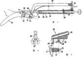
图1根据本发明的插入工具的一个实施例的视图,其装有内假体并处于夹紧状态下;Figure 1 is a view of an embodiment of an insertion tool according to the invention, fitted with an endoprosthesis and in a clamped state;
图2根据图1的插入工具处于松开状态下的视图;Figure 2 is a view of the insertion tool according to Figure 1 in a released state;
图3在图1中所示的插入工具的部分剖视图;Figure 3 is a partial cross-sectional view of the insertion tool shown in Figure 1;
图4在图1中所示插入工具的夹紧装置的一部分的前视图;Figure 4 is a front view of a part of the clamping device of the insertion tool shown in Figure 1;
图5夹紧装置的部分剖视图,带有待容纳的内假体。Fig. 5 Partial sectional view of the clamping device with the endoprosthesis to be accommodated.
具体实施方式Detailed ways
根据本实施例的插入工具通常为一种夹钳式的基本结构,其在后部区域具有握持件,在前部区域具有夹紧件29(随后称作夹紧装置)。这两个区域通过回转铰链29分开。握持件具有2个棒状地向后延伸的手柄21、22。它们在压合状态时可借助卡锁装置24固定。The insertion tool according to the present embodiment generally has a pliers-like basic structure with a gripping part in the rear area and a clamping part 29 (hereinafter referred to as clamping device) in the front area. The two areas are separated by a
插入工具的总体用标记2表示。夹紧装置20布置在该插入工具的前端部。该夹紧装置主要由叉子25构成,该叉子25在与手柄21相连接的腿的前端部上。该叉子具有容纳开口。待夹紧的内假体1插入到该容纳开口中。此外,夹紧装置20在由手柄22所形成的腿的前端部上具有对向支承件。该对向支承件通过滑块26形成。该滑块可摆动地设置在上述前端部上,这样在夹紧装置20关闭和打开时,滑块执行滑动的向前和向后运动。滑块26具有面朝保持叉25的端面。在该端面上设置有两个凸起28。这些凸起构造为销钉式,并且具有约4mm的长度。它们这样取向,使得它们对准保持叉25,确切地说是对准保持叉的开口区域。The totality of the insertion tool is indicated by
现在描述插入工具中的导轨的结构。手柄21在它的后部区域中构造成管状的。该把手具有在它的整个长度上延伸的孔23。该孔用作冲杆31的导轨。冲杆31构造成一种敲击工具,并主要由分成两个区段34、35的、且具有修圆的顶端36的杆构成。在冲杆31的后端部设置有由手术者操作的把手32。同其它的插入工具一样,冲杆31由优质钢制成。由于冲杆31包括把手32的质量,在许多情况中可通过手的力达到足够的敲击作用。当出现要求有更高的敲击作用时,在把手32的背面设置砧面33。可用锤击对它施加作用,这样,可明显地增大可由顶端36传递的敲击作用。The structure of the guide rail inserted into the tool will now be described. The
在冲杆31上,在它的外表面上在第一区段34的区域中构造有圆周槽37。在这个圆周槽中设置有O形圈38。该O形圈的尺寸是如此确定的,使得它不和杆区段34的表面平齐,而是如此程度地伸出来,使它和孔31的内壁相接触。通过这一措施,O形圈施加一种摩擦力。这种摩擦力和冲杆31的运动方向相反。通过这一措施可在很大程度上阻止在敲击作用后,特别是在锤击砧面33时,冲杆31发生反弹。A circumferential groove 37 is formed on the
为了阐明插入工具的作用方式,下面对待植入的内假体作简短说明。内假体是指一种杆状假体,例如它形成总的髋关节假体的股骨部分。杆状假体主要由纵向弯曲延伸的杆部部分10、支承凸缘11和在支承凸缘上突起的颈部部分14构成。在颈部部分14的外部区域中构造有锥体13。它用于容纳铰链球。在这种情况中,锥体13的表壳面以及它的端面16确定了铰链球(未示出)的位置。这些表面精确地制成,并且必须予以保护,防止损伤。杆部部分10用于植入到之前已打开的股骨的骨髓腔中。杆部部分10可以构造成有粘合剂和无粘合剂的植入。正是在无粘合剂的植入的情况下,与骨髓腔中周围的结构有良好的形状配合很重要。在插入或者在撞入时,内假体1或者杆部部分10的方向变化会导致在骨髓腔中的扩张,这样就损害了形状配合,并且因此减小了内假体在股骨中锚定的稳定性和可靠性。为了在插入和撞入时能对内假体1进行可靠的导向,将内假体夹紧在插入工具2上。这是使用夹紧装置20以下述描述方式进行的。In order to clarify the mode of action of the insertion tool, a short description of the endoprosthesis to be implanted follows. Endoprosthesis refers to a rod-shaped prosthesis, such as the femoral part, which forms the total hip prosthesis. The rod-shaped prosthesis essentially consists of a longitudinally
夹紧装置20构造成通过其保持叉25和其对向支承件26,在颈部部分14的锥体13上将内假体1保持住。在保持叉25中设置有圆形的台阶。该台阶用作锥体13的下边缘15的支座27。支座27的深度是如此选择的,使得锥体13进入到保持叉25中大约1mm。只有在这个区域中才出现保持叉25和锥体13之间的接触。这个区域典型地对于和铰链头的连接是不重要的,因为铰链头没有如此远地延伸到锥体13。支座27在锥体13的其它区域内不施加作用,因此其得到保护,不受损害。对向支承件26和锥体13的端面16共同作用。但是它并不直接位于端面16上,而是用它的凸起28嵌接到锥体13的端面16上的相应凹槽18中。其中凸起28的高度比凹槽18的深度略大。事实证明,当凹槽18的深度为3mm时,凸起28的高度为4mm是合适的。通过这一措施使凸起28用它的顶端靠放在凹槽18的底部,而端面16本身并没有和滑块26接触。其保留有大约1mm的安全间隙。通过压合握持件21和22,带有凸起28的滑块26向前(沿着夹紧方向)移动。其中,凸起28进入到凹槽18中,并且压迫锥体13以其下边缘15进入到保持叉25的支座27中。这样,内假体1被牢固地夹紧到插入工具上。通过凸起28确定了角度位置。因此这些凸起用作位置标记机构。现在手术者就能够可靠和位置准确地控制内假体1。The clamping
在植入的第一步骤中,内假体1用它的杆部10借助插入工具2植入到骨髓腔中。由于杆部的锥度,通常无需花特别的力气就达到杆部10的大约2/3至3/4的长度。然后拉得越来越紧的假体杆部10的支座在骨髓腔床中需要越来越大的力气,直到必须对内假体1进行锤击,以使它达到最终位置。这可采用根据本发明的插入工具实现,而无须将该工具取下。手术者借助把手32操作冲杆31。其中具有对向支承件26的保持叉25的布置如此地和孔23的位置相协调一致,使得如此地选择由该孔所确定的冲杆的路径30,即顶端36在凸缘11上碰到内假体1。由冲杆31所传递的脉动因此直接传递到凸缘11上,并且因此传递到杆部10上,而不给锥体13和颈部部分14施加载荷。这种直接传递不仅保护了内假体1的锥体13和颈部部分14,而且还能通过冲杆31的比较小的敲击达到高的锤入效果。In a first step of implantation, the endoprosthesis 1 is implanted with its
内假体相对于冲杆的路径30布置的角度(角度α)大约为20度至40度(优选为25度),并且如此进行选择,使得在内假体1的位置中-在此位置中为了锤入需要最大的力-导向路径30大约垂直于骨头的切面。这样保证这个要求特别大的力气的部段能有最佳的力传递。The angle at which the endoprosthesis is arranged relative to the
在根据本发明的插入工具中,可将内假体位置和角度准确地夹紧在插入工具上,并且在这个规定好的位置中将内假体精确地植入到骨髓腔中。可用该插入工具进行为了达到内假体的最终固定位置所要求的后敲击,其中,通过冲杆31的导向保证将锤击的脉动力引导到内假体1的凸缘11上的有利位置上。在这种情况中使内假体1的敏感的锥体13得到保护,使其免受敲击力。内假体的敲入可使用集成其中的冲杆31进行而无须更换工具。在必要时可通过冲杆31的后端部上的砧面33,附加地用锤子进行后期敲击。With the insertion tool according to the invention, the endoprosthesis can be clamped precisely positionally and angularly on the insertion tool, and in this defined position the endoprosthesis can be inserted precisely into the medullary canal. This insertion tool can be used to carry out the post-percussion required to achieve the final fixation position of the endoprosthesis, wherein the guidance by the
Claims (15)
Translated fromChineseApplications Claiming Priority (3)
| Application Number | Priority Date | Filing Date | Title |
|---|---|---|---|
| DE202005014270.0 | 2005-09-09 | ||
| DE202005014270UDE202005014270U1 (en) | 2005-09-09 | 2005-09-09 | Insertion aid for femur implant, comprises guiding unit for striker and particularly safe holding arrangement |
| PCT/EP2006/008679WO2007028588A2 (en) | 2005-09-09 | 2006-09-06 | Insertion instrument for an endoprosthesis comprising a prosthesis shaft which is to be inserted into a marked chamber |
Publications (2)
| Publication Number | Publication Date |
|---|---|
| CN101257867A CN101257867A (en) | 2008-09-03 |
| CN101257867Btrue CN101257867B (en) | 2010-12-15 |
Family
ID=37681424
Family Applications (1)
| Application Number | Title | Priority Date | Filing Date |
|---|---|---|---|
| CN2006800326989AExpired - Fee RelatedCN101257867B (en) | 2005-09-09 | 2006-09-06 | Insertion tool for endoprostheses having a prosthesis stem inserted in the medullary cavity |
Country Status (13)
| Country | Link |
|---|---|
| US (1) | US8157808B2 (en) |
| EP (1) | EP1922035B1 (en) |
| JP (1) | JP5099521B2 (en) |
| KR (1) | KR101317052B1 (en) |
| CN (1) | CN101257867B (en) |
| AU (1) | AU2006289304B2 (en) |
| BR (1) | BRPI0614856A2 (en) |
| CA (1) | CA2621008C (en) |
| DE (1) | DE202005014270U1 (en) |
| ES (1) | ES2458302T3 (en) |
| RU (1) | RU2412675C2 (en) |
| WO (1) | WO2007028588A2 (en) |
| ZA (1) | ZA200802154B (en) |
Families Citing this family (35)
| Publication number | Priority date | Publication date | Assignee | Title |
|---|---|---|---|---|
| NZ548878A (en) | 2006-08-01 | 2008-11-28 | Enztec Ltd | Improved impactor |
| US20080255565A1 (en)* | 2006-11-20 | 2008-10-16 | Fletcher Henry H | Broach handle for minimally invasive hip replacement surgery |
| US11484627B2 (en) | 2010-10-20 | 2022-11-01 | 206 Ortho, Inc. | Method and apparatus for treating bone fractures, and/or for fortifying and/or augmenting bone, including the provision and use of composite implants, and novel composite structures which may be used for medical and non-medical applications |
| EP2629780A4 (en) | 2010-10-20 | 2014-10-01 | 206 Ortho Inc | Implantable polymer for bone and vascular lesions |
| WO2015095745A1 (en) | 2010-10-20 | 2015-06-25 | 206 Ortho, Inc. | Method and apparatus for treating bone fractures, and/or for fortifying and/or augmenting bone, including the provision and use of composite implants, and novel composite structures which may be used for medical and non-medical applications |
| US10525169B2 (en) | 2010-10-20 | 2020-01-07 | 206 Ortho, Inc. | Method and apparatus for treating bone fractures, and/or for fortifying and/or augmenting bone, including the provision and use of composite implants, and novel composite structures which may be used for medical and non-medical applications |
| US11207109B2 (en) | 2010-10-20 | 2021-12-28 | 206 Ortho, Inc. | Method and apparatus for treating bone fractures, and/or for fortifying and/or augmenting bone, including the provision and use of composite implants, and novel composite structures which may be used for medical and non-medical applications |
| US11058796B2 (en) | 2010-10-20 | 2021-07-13 | 206 Ortho, Inc. | Method and apparatus for treating bone fractures, and/or for fortifying and/or augmenting bone, including the provision and use of composite implants, and novel composite structures which may be used for medical and non-medical applications |
| US11291483B2 (en) | 2010-10-20 | 2022-04-05 | 206 Ortho, Inc. | Method and apparatus for treating bone fractures, and/or for fortifying and/or augmenting bone, including the provision and use of composite implants |
| KR101220953B1 (en)* | 2011-06-23 | 2013-01-22 | 주식회사 코렌텍 | A Rasp Handle |
| EP2819620A4 (en) | 2012-02-29 | 2015-11-04 | 206 Ortho Inc | METHOD AND DEVICE FOR TREATING BONE BREAKS USING COMPOUND IMPLANTS |
| US9084685B2 (en)* | 2012-09-28 | 2015-07-21 | DePuy Synthes Products, Inc. | Femoral prosthesis with insertion/extraction feature |
| DE102013200924A1 (en)* | 2013-01-22 | 2014-07-24 | Erich Johann Müller | Razor tool for minimally invasive prosthesis revision |
| BR112015026709A8 (en) | 2013-04-26 | 2019-12-24 | Smith & Nephew Inc | proof medical instrument for acetabular component alignment, alignment and implantation system, fixed format medical instrument and alignment and implantation methods |
| JP2016525379A (en) | 2013-05-23 | 2016-08-25 | 206 オーソ,インコーポレーテッド | Methods and apparatus for treating fractures and / or for reinforcing and / or augmenting bone, including the provision and use of composite implants |
| US10456264B2 (en) | 2014-01-24 | 2019-10-29 | Tornier, Inc. | Humeral implant anchor system |
| US12023253B2 (en) | 2014-01-24 | 2024-07-02 | Howmedica Osteonics Corp. | Humeral implant anchor system |
| GB201519629D0 (en)* | 2015-11-06 | 2015-12-23 | Embody Orthopaedic Ltd | Holder for resurfacing head implant |
| US10463499B2 (en) | 2016-03-25 | 2019-11-05 | Tornier, Inc. | Stemless shoulder implant with fixation components |
| EP3248552A1 (en)* | 2016-05-25 | 2017-11-29 | WALDEMAR LINK GmbH & Co. KG | Tool for the production of a recess in bone tissue |
| US11129724B2 (en) | 2016-07-28 | 2021-09-28 | Howmedica Osteonics Corp. | Stemless prosthesis anchor component |
| MX2020003194A (en) | 2017-09-25 | 2020-12-09 | Howmedica Osteonics Corp | Patient specific stemless prosthesis anchor components. |
| US11399948B2 (en) | 2017-12-11 | 2022-08-02 | Howmedica Osteonics Corp. | Stemless prosthesis anchor components and kits |
| US20210330476A1 (en)* | 2018-03-01 | 2021-10-28 | Alden Kris | Prosthetic componenet extractor |
| EP4257090A3 (en) | 2018-10-02 | 2023-12-13 | Howmedica Osteonics Corp. | Shoulder prosthesis components and assemblies |
| US11723781B2 (en)* | 2019-01-09 | 2023-08-15 | Shukla Medical | Implant extractor |
| EP4527357A3 (en)* | 2019-10-01 | 2025-06-04 | Howmedica Osteonics Corporation | Shoulder prosthesis components and assemblies |
| US11779468B2 (en)* | 2020-04-14 | 2023-10-10 | Shukla Medical | Implant extractor |
| US12011203B2 (en)* | 2021-05-07 | 2024-06-18 | DePuy Synthes Products, Inc. | Offset acetabular shell impactor adapter |
| US20230000644A1 (en)* | 2021-07-02 | 2023-01-05 | Shukla Medical | Implant extractor |
| CN113974761B (en)* | 2021-11-30 | 2023-06-20 | 优适医疗科技(苏州)有限公司 | Hip joint femur lateral medullary cavity file auxiliary device |
| AU2023201257A1 (en)* | 2022-03-02 | 2023-09-21 | Howmedica Osteonics Corp. | Bone reattachment system |
| CN114795601B (en)* | 2022-06-29 | 2022-09-02 | 深圳市迈捷生命科学有限公司 | Implant structure for fixing orthopaedic prosthesis |
| GB202215748D0 (en)* | 2022-10-24 | 2022-12-07 | Depuy Ireland Ultd Co | Improvements in and relating to surgical instruments |
| US20240325168A1 (en)* | 2023-03-29 | 2024-10-03 | DePuy Synthes Products, Inc. | Orthopaedic surgical instrument for extracting a femoral stem component in a hip replacement surgical procedure and method of using the same |
Citations (9)
| Publication number | Priority date | Publication date | Assignee | Title |
|---|---|---|---|---|
| US4936863A (en)* | 1988-05-13 | 1990-06-26 | Hofmann Aaron A | Hip prosthesis |
| EP0485065A2 (en)* | 1990-11-05 | 1992-05-13 | Bristol-Myers Squibb Company | Prosthetic hip stem implant with torque adapter |
| CN2118508U (en)* | 1991-12-30 | 1992-10-14 | 吉林市中心医院 | Carbon-titanium combined artificial thighbone |
| CN2322572Y (en)* | 1998-03-25 | 1999-06-09 | 周袭明 | Tuna shape hip joint prosthesis |
| CN2383493Y (en)* | 1999-07-22 | 2000-06-21 | 周袭明 | Bone cement type Jitan series hip joint prosthesis |
| US6322564B1 (en)* | 1998-06-18 | 2001-11-27 | Depuy Orthopaedics, Inc. | Proximal alignment insertion guide and method therefor |
| CN1373647A (en)* | 1999-09-13 | 2002-10-09 | 比约恩·弗朗克·艾弗森 | A tool for controlling the angle between the parts of an artificial hip joint |
| CN1794952A (en)* | 2003-03-24 | 2006-06-28 | 奥索仪表公司 | System, method and tool for ensuring correct insertion of an artificial hip joint |
| CN1822804A (en)* | 2003-07-15 | 2006-08-23 | 颈椎修复技术公司 | Insertion instrument for cervical prostheses |
Family Cites Families (12)
| Publication number | Priority date | Publication date | Assignee | Title |
|---|---|---|---|---|
| DE2101002C2 (en)* | 1971-01-11 | 1973-01-04 | Aesculap-Werke Ag Vormals Jetter & Scheerer, 7200 Tuttlingen | Surgical instrument for driving in and pulling out a joint head prosthesis |
| FR2627983B1 (en)* | 1988-03-02 | 1997-05-16 | Vecteur Orthopedic Sa | DEVICE FOR PLACING FEMALE HIP PROSTHESES |
| SU1680149A1 (en)* | 1988-11-23 | 1991-09-30 | Dzhabbarly Chingiz R | Hip joint endoprosthesis |
| US5476466A (en)* | 1993-07-20 | 1995-12-19 | Zimmer, Inc. | Orthopaedic positioning instrument |
| JPH0737118U (en)* | 1993-12-27 | 1995-07-11 | 株式会社神戸製鋼所 | Stem protector remover |
| US5993455A (en) | 1996-11-13 | 1999-11-30 | Noble; Philip C. | Surgical broach and methods for preparing the medullary cavity of a femur in hip arthroplasty |
| US6113605A (en)* | 1998-03-02 | 2000-09-05 | Benoist Girard & Cie | Prosthesis inserter |
| GB9804473D0 (en)* | 1998-03-02 | 1998-04-29 | Benoist Girard & Cie | Prosthesis inserter |
| DE29807671U1 (en) | 1998-04-28 | 1999-09-02 | Link Waldemar Gmbh Co | Surgical instrument |
| US6165177A (en)* | 1998-12-24 | 2000-12-26 | Depuy Orthopaedics, Inc. | Alignment guide for insertion of stem prosthesis |
| FR2839641B1 (en)* | 2002-05-17 | 2004-08-13 | Jean Claude Cartillier | FEMALE HIP PROSTHESIS |
| US7585301B2 (en)* | 2002-06-12 | 2009-09-08 | Howmedica Osteonics Corp. | Modular hip inserter/positioner |
- 2005
- 2005-09-09DEDE202005014270Upatent/DE202005014270U1/ennot_activeExpired - Lifetime
- 2006
- 2006-09-06CNCN2006800326989Apatent/CN101257867B/ennot_activeExpired - Fee Related
- 2006-09-06JPJP2008530386Apatent/JP5099521B2/ennot_activeExpired - Fee Related
- 2006-09-06WOPCT/EP2006/008679patent/WO2007028588A2/enactiveApplication Filing
- 2006-09-06AUAU2006289304Apatent/AU2006289304B2/ennot_activeCeased
- 2006-09-06RURU2008113186/14Apatent/RU2412675C2/ennot_activeIP Right Cessation
- 2006-09-06ESES06791866.4Tpatent/ES2458302T3/enactiveActive
- 2006-09-06USUS11/997,593patent/US8157808B2/ennot_activeExpired - Fee Related
- 2006-09-06BRBRPI0614856-5Apatent/BRPI0614856A2/ennot_activeApplication Discontinuation
- 2006-09-06KRKR1020087004186Apatent/KR101317052B1/ennot_activeExpired - Fee Related
- 2006-09-06EPEP06791866.4Apatent/EP1922035B1/ennot_activeNot-in-force
- 2006-09-06CACA2621008Apatent/CA2621008C/ennot_activeExpired - Fee Related
- 2008
- 2008-03-07ZAZA200802154Apatent/ZA200802154B/enunknown
Patent Citations (9)
| Publication number | Priority date | Publication date | Assignee | Title |
|---|---|---|---|---|
| US4936863A (en)* | 1988-05-13 | 1990-06-26 | Hofmann Aaron A | Hip prosthesis |
| EP0485065A2 (en)* | 1990-11-05 | 1992-05-13 | Bristol-Myers Squibb Company | Prosthetic hip stem implant with torque adapter |
| CN2118508U (en)* | 1991-12-30 | 1992-10-14 | 吉林市中心医院 | Carbon-titanium combined artificial thighbone |
| CN2322572Y (en)* | 1998-03-25 | 1999-06-09 | 周袭明 | Tuna shape hip joint prosthesis |
| US6322564B1 (en)* | 1998-06-18 | 2001-11-27 | Depuy Orthopaedics, Inc. | Proximal alignment insertion guide and method therefor |
| CN2383493Y (en)* | 1999-07-22 | 2000-06-21 | 周袭明 | Bone cement type Jitan series hip joint prosthesis |
| CN1373647A (en)* | 1999-09-13 | 2002-10-09 | 比约恩·弗朗克·艾弗森 | A tool for controlling the angle between the parts of an artificial hip joint |
| CN1794952A (en)* | 2003-03-24 | 2006-06-28 | 奥索仪表公司 | System, method and tool for ensuring correct insertion of an artificial hip joint |
| CN1822804A (en)* | 2003-07-15 | 2006-08-23 | 颈椎修复技术公司 | Insertion instrument for cervical prostheses |
Also Published As
| Publication number | Publication date |
|---|---|
| EP1922035A2 (en) | 2008-05-21 |
| JP2009507587A (en) | 2009-02-26 |
| ZA200802154B (en) | 2009-05-27 |
| AU2006289304B2 (en) | 2011-08-25 |
| DE202005014270U1 (en) | 2007-01-11 |
| JP5099521B2 (en) | 2012-12-19 |
| US20080221576A1 (en) | 2008-09-11 |
| RU2412675C2 (en) | 2011-02-27 |
| WO2007028588A3 (en) | 2007-06-28 |
| US8157808B2 (en) | 2012-04-17 |
| CA2621008A1 (en) | 2007-03-15 |
| AU2006289304A1 (en) | 2007-03-15 |
| RU2008113186A (en) | 2009-10-20 |
| EP1922035B1 (en) | 2014-01-22 |
| CN101257867A (en) | 2008-09-03 |
| BRPI0614856A2 (en) | 2011-04-19 |
| KR101317052B1 (en) | 2013-10-11 |
| CA2621008C (en) | 2013-01-08 |
| WO2007028588A2 (en) | 2007-03-15 |
| ES2458302T3 (en) | 2014-04-30 |
| KR20080043785A (en) | 2008-05-19 |
Similar Documents
| Publication | Publication Date | Title |
|---|---|---|
| CN101257867B (en) | Insertion tool for endoprostheses having a prosthesis stem inserted in the medullary cavity | |
| US4809689A (en) | Drilling system for insertion of an endoprosthesis | |
| US10660767B2 (en) | Assembler for modular prosthesis | |
| EP1707160B1 (en) | Controlled force impacting device | |
| US7037311B2 (en) | Tool for gripping an orthopedic implant | |
| US20080262503A1 (en) | Surgical Tool and Method | |
| US8080015B2 (en) | Impacting device and method | |
| EP0978262B1 (en) | Alignment guide for slotted prosthetic stem | |
| US8361077B2 (en) | Insertion instrument for joint sockets of prostheses | |
| CN108135586B (en) | Ball and cup impactor for implanting hip prosthesis | |
| US20220233337A1 (en) | Trial neck piece for a joint endoprosthesis | |
| US12383324B2 (en) | Straight and curved femoral broach impactor adapters | |
| AU2008200892A1 (en) | Apparatus for indicating the bone thickness between a cavity in a bone and the bone surface | |
| JP2024516854A (en) | Offset Acetabular Shell Impactor Adapter | |
| EP3799842A1 (en) | Medical implant extractor | |
| KR200251314Y1 (en) | Impactor for Surgery | |
| HK40052289A (en) | Ball and cup impactors for implanting a hip prosthesis | |
| CZ27011U1 (en) | Extractor of hip endoprosthesis stem |
Legal Events
| Date | Code | Title | Description |
|---|---|---|---|
| C06 | Publication | ||
| PB01 | Publication | ||
| C10 | Entry into substantive examination | ||
| SE01 | Entry into force of request for substantive examination | ||
| C14 | Grant of patent or utility model | ||
| GR01 | Patent grant | ||
| CF01 | Termination of patent right due to non-payment of annual fee | ||
| CF01 | Termination of patent right due to non-payment of annual fee | Granted publication date:20101215 Termination date:20210906 |