CN101254503B - Multipurpose Parts Water Washer - Google Patents
Multipurpose Parts Water WasherDownload PDFInfo
- Publication number
- CN101254503B CN101254503BCN2008100822570ACN200810082257ACN101254503BCN 101254503 BCN101254503 BCN 101254503BCN 2008100822570 ACN2008100822570 ACN 2008100822570ACN 200810082257 ACN200810082257 ACN 200810082257ACN 101254503 BCN101254503 BCN 101254503B
- Authority
- CN
- China
- Prior art keywords
- cleaning
- parts
- fluid
- chamber
- liquid
- Prior art date
- Legal status (The legal status is an assumption and is not a legal conclusion. Google has not performed a legal analysis and makes no representation as to the accuracy of the status listed.)
- Expired - Fee Related
Links
Images


Classifications
- B—PERFORMING OPERATIONS; TRANSPORTING
- B08—CLEANING
- B08B—CLEANING IN GENERAL; PREVENTION OF FOULING IN GENERAL
- B08B3/00—Cleaning by methods involving the use or presence of liquid or steam
- B08B3/006—Cabinets or cupboards specially adapted for cleaning articles by hand
- B—PERFORMING OPERATIONS; TRANSPORTING
- B08—CLEANING
- B08B—CLEANING IN GENERAL; PREVENTION OF FOULING IN GENERAL
- B08B3/00—Cleaning by methods involving the use or presence of liquid or steam
- B08B3/02—Cleaning by the force of jets or sprays
- B—PERFORMING OPERATIONS; TRANSPORTING
- B08—CLEANING
- B08B—CLEANING IN GENERAL; PREVENTION OF FOULING IN GENERAL
- B08B2203/00—Details of cleaning machines or methods involving the use or presence of liquid or steam
- B08B2203/007—Heating the liquid
Landscapes
- Cleaning By Liquid Or Steam (AREA)
Abstract
Description
Translated fromChinese相关申请related application
本申请是2007年3月2日提出的、名称为多用途零件水清洗机的美国部分继续专利申请11/681,652,并要求所述申请的权益和优先权,所述申请清楚地接合于此供参考。This application is a Continuation-in-Part of U.S.
技术领域technical field
本公开总体涉及一种用于清洗油脂、油、污物或其它来自机械零件的碎屑的多用途零件水清洗机,更特别地,涉及一种具有外壳的零件清洗机,所述清洗机具有用于清洁零件的自动喷洗部、浸泡搅动部和手动贮槽清洗部。The present disclosure relates generally to a multipurpose aqueous parts washer for cleaning grease, oil, dirt, or other debris from machine parts, and more particularly, to a parts washer having a housing with Automatic spray wash section, immersion agitation section and manual sump wash section for cleaning parts.
背景技术Background technique
本公开涉及一种采用多用途零件水清洗机清洗机械零件的设备。机械零件在正常操作中收集污物、磨损残留物、用过的油脂或其它碎屑。在周期性的维护、额外维护、修理、甚至预定的升级过程中,需要从较大的机械元件、例如汽车发动机中机械分解零件。单独的零件和部件在它们扔掉、诊断或最后重新安装到机械装置上之前,或在修理以便进一步使用之前,必须清洗。The present disclosure relates to a device for cleaning mechanical parts using a multipurpose parts water washer. Mechanical parts collect dirt, wear residue, used grease or other debris during normal operation. During periodic maintenance, additional maintenance, repairs, or even scheduled upgrades, there is a need to mechanically disassemble parts from larger mechanical elements, such as automotive engines. Individual parts and components must be cleaned before they are thrown away, diagnosed or finally reinstalled on a mechanism, or repaired for further use.
零件清洗机是清洗单个的或成组的零件(包括但不限于机器和机械零件)的设备。零件清洗机还能够清洗诸如链条、工具或其它易于接触涂油脂或涂油零件的元件。这些柜大小的装置是任何需要在车间清洗零件的机修工或其它工人必不可少的工具。例如,汽车修理工将零件清洗机放置在工具旁或靠近他们工作区的地方。A parts washer is a device for cleaning individual or grouped parts (including but not limited to machine and mechanical parts). Parts washers are also capable of cleaning elements such as chains, tools, or other components that come into contact with greased or oiled parts. These cabinet-sized units are an essential tool for any mechanic or other worker who needs to clean parts on the shop floor. For example, auto mechanics place parts washers next to their tools or close to their work area.
与零件清洗机相关的核心技术不是不像与厨房器具和其它食品制备附件的清洗相关的技术,显著的区别在于在废水排入环境之前必须控制机械零件清洗机残余物。因此,必须经常使用不同的清洗液,通常一旦污物变干则很少清洗零件,必须收集并限制油基废水,必须收集并像淤泥一样过滤不能溶解的碎屑,并且要更新清洗液。使用零件清洗机的车间的环境也是不同的。有的零件清洗机采用水清洗液去溶解并除去油脂、碳、树脂、焦油、墨水和其它碎屑。这些零件清洗机采用共同的或各自的水、肥皂和/或清洗液。其它更具侵蚀性的零件清洗机使用碳氢化合物基溶剂或其它溶剂去除油脂和清洗零件。通过本公开还能想到的是采用任何类型清洗液的零件清洗机,但是更优选的是采用水基清洗液的零件清洗机。The core technology associated with parts washer is not unlike that associated with the cleaning of kitchen utensils and other food preparation accessories, with the notable difference that mechanical parts washer residues must be controlled before wastewater is discharged into the environment. Therefore, different cleaning fluids must be used frequently, parts are usually washed infrequently once the soil dries, oil-based waste water must be collected and limited, insoluble debris must be collected and filtered like sludge, and the cleaning fluid is renewed. The environment of a shop where a parts washer is used is also different. Some parts washers use an aqueous cleaning solution to dissolve and remove grease, carbon, resin, tar, ink, and other debris. These parts washers use common or individual water, soap and/or cleaning fluids. Other, more aggressive parts washers use hydrocarbon-based or other solvents to degrease and clean parts. Also contemplated by this disclosure are parts washers employing any type of wash fluid, but parts washers employing water-based wash fluids are more preferred.
为方便使用,零件清洗机通常存储在零件可移动或加工的地方。与车间相关的狭窄空间和其它限制准许紧凑和便携的装置。零件清洗机在艰苦的环境下还必须是坚固和耐用的。四种不同的技术为行业所知:手动零件清洗、自动零件清洗、喷射浸没清洗和浸泡零件清洗。手动零件清洗机通常类似于置于容纳清洗流体的储器上的贮槽。手动零件清洗机的操作者可以推动踏板或采取另外的动作去致动位于储器内的泵和加热元件,以使清洗流体循环。手动零件清洗机的优点有很多。例如,允许触觉感知细微层的污物,集中精力清洗专门位置,由操作者直接进行清洗。For ease of use, parts washers are often stored where parts can be moved or processed. The tight spaces and other constraints associated with a workshop permit a compact and portable device. Parts washers must also be robust and durable in harsh environments. Four different techniques are known in the industry: manual parts cleaning, automatic parts cleaning, jet immersion cleaning and immersion parts cleaning. Manual parts washers are generally similar to a sump placed on a reservoir that holds the cleaning fluid. An operator of a manual parts washer may push a pedal or take another action to actuate a pump and heating element located within the reservoir to circulate the washing fluid. The advantages of a manual parts washer are many. For example, allowing tactile perception of dirt in a fine layer, focusing on cleaning a specific location, and cleaning directly by the operator.
自动零件清洗机通常包括外壳,所述外壳在该外壳内保持一些用于存储和移除零件的篮子。自动装置具有大的入口门、用于程控喷射循环的控制设备和用于活化装置中的清洗液的泵/加热器。自动零件清洗机相对于手动零件清洗机的优点包括节约时间、能够在清洗之间将脏的零件存储于外壳内、在非工作时间(off-hours)期间清洗零件、能够使用人舒适范围之外的压力和温度,最重要的是减少了清洗过程中操作者弄脏他的手的需要。用于清洗零件的其它技术包括浸泡和搅动,其中零件被以一定容积浸没并且置于持续的再生的清洗液液流、或在再生液流中具有一系列浸泡喷射,或置于横向流动的清洗液中。这些清洗机允许通过使用相对少量的清洁流体来慢慢地移除附着的污物。Automatic parts washers typically include a housing that holds within the housing a number of baskets for storing and removing parts. The automatic unit has a large entry door, control equipment for programmed spray cycles and a pump/heater for activating the cleaning fluid in the unit. Advantages of automatic parts washers over manual parts washers include saving time, the ability to store dirty parts in enclosures between washes, washing parts during off-hours, and the ability to use them outside of one's comfort zone pressure and temperature, and most importantly reduces the need for the operator to get his hands dirty during the cleaning process. Other techniques used to clean parts include immersion and agitation, where parts are submerged in volume and placed in a continuous stream of regenerated cleaning fluid, or with a series of soak jets in a stream of regenerated fluid, or in a cross-flow wash in the liquid. These washers allow for the slow removal of attached dirt by using relatively small amounts of cleaning fluid.
这些不同技术的每个具有其独特的优点和缺点。如果想要不同的优点,由于不同装置之间零件、清洗液、碎屑和淤泥的处理相差很大,因此在当前需要不同的清洗机。所需要的是这样一种装置,它能够提供与这些单个设备中的技术的每一种相关的优点,能够解决与这些类型的清洗机相关的限制。还需要的是与用多种清洗液的单一装置的使用相关的多个有效和实用的改进。Each of these different technologies has its own unique advantages and disadvantages. If different advantages are desired, different washers are currently required as the handling of parts, cleaning fluids, debris and sludge varies greatly from installation to installation. What is needed is an arrangement that can provide the advantages associated with each of these technologies in a single device, while addressing the limitations associated with these types of washers. What is also needed are efficient and practical improvements related to the use of a single device with multiple cleaning fluids.
发明内容Contents of the invention
本公开的一个方面总体上涉及一种用于清除油脂、油、来自机械零件的污物的多用途零件清洗机,更特别地,涉及一种用于清洗零件的设备,该设备在单一壳体内包括具有用于喷射零件的第一清洗腔和用于浸泡或搅动零件的第二清洗腔的自动清洗部、和手动清洗部。所述多用途零件清洗机可以包括:三个清洗部,所有部由单个泵提供清洗液;储液部,其用于收集和存储大量清洗液和来自清洗过程的碎屑;单一控制器界面,其根据显示装置进行操作;和热能源,其用于加热清洗液。所述多用途设计还可以包括其它新颖的特征,例如使用在储液部内的液下泵、用于泵马达的方便进入板、控制器、显示装置、用作自动部的安全盖并收集手动清洗部的清洗液且围住自动清洗部的整体式贮槽,以及使用定时器和方便每个清洗部的操作的多色显示装置。所述设计还可以包括并存的多功能清洗特征、热触发安全盖、浸泡搅拌槽和可移除的平的或V形碎屑盘。One aspect of the present disclosure relates generally to a multipurpose parts washer for removing grease, oil, dirt from mechanical parts, and more particularly, to an apparatus for washing parts within a single housing An automatic cleaning section with a first cleaning chamber for spraying the parts and a second cleaning chamber for soaking or agitating the parts, and a manual cleaning section are included. The multipurpose parts washer may include: three wash sections, all supplied with wash fluid by a single pump; a reservoir for collecting and storing large quantities of wash fluid and debris from the wash process; a single controller interface, It operates according to the display device; and a thermal energy source is used to heat the cleaning fluid. The multipurpose design may also include other novel features such as the use of a sump pump within the reservoir, an easy access plate for the pump motor, controls, display, safety cover for use as an automatic section and to collect manual cleaning There is an integral storage tank for the cleaning liquid in the cleaning section and surrounds the automatic cleaning section, as well as a multi-color display device that uses a timer and facilitates the operation of each cleaning section. The design may also include concurrent multi-function cleaning features, heat-triggered safety lids, immersion agitation tanks, and removable flat or V-shaped debris trays.
附图说明Description of drawings
在接合附图、附图说明、发明内容、摘要、背景技术、技术领域和相应标题阅读时,下面的公开总体上可以通过参考提供的具体实施方式而得到最好的理解。不同附图中的相同的附图标记表示相同的元件或功能上等同的元件。发明内容和摘要中的元件没有带标记,然而涉及相应于具体实施方式和相关公开的元件。The following disclosure is generally best understood by reference to the Detailed Description provided when read in conjunction with the Drawings, Drawings Description, Summary, Abstract, Background, Technical Field and corresponding headings. The same reference numbers in different drawings identify the same elements or functionally equivalent elements. Elements in the Summary and Abstract are not labeled, but refer to elements corresponding to the Detailed Description and related disclosures.
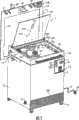
图1是根据本公开的一个实施例的多用途零件水清洗机的部分分解透视图,其中手动清洗部处于打开构造,可拉出架示出为部分移出。FIG. 1 is a partially exploded perspective view of a multi-purpose aqueous parts washer according to one embodiment of the present disclosure, with the manual wash section in an open configuration and the pull-out shelf shown partially removed.
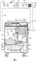
图2是图1的多用途零件水清洗机的透视图,其中没有可拉出架,透明示出内部部分,并且在搅拌槽中具有清洗液。FIG. 2 is a perspective view of the multipurpose aqueous parts washer of FIG. 1 without the pull-out shelf, with the interior portions shown transparently, and with the cleaning fluid in the agitation tank.
图3是图1的多用途零件水清洗机的透视图,其中手动清洗部处于闭合构造。3 is a perspective view of the multipurpose aqueous parts washer of FIG. 1 with the manual wash section in a closed configuration.
图4是图1的多用途零件水清洗机处于所述构造并如图2所示沿着线4-4的侧视图。4 is a side view of the multipurpose aqueous parts washer of FIG. 1 in the described configuration and as shown in FIG. 2 along line 4-4.
图5是图1中多用途零件水清洗机处于所述构造并如图2所示沿着线5-5的侧视图。5 is a side view of the multipurpose aqueous parts washer of FIG. 1 in the described configuration and as shown in FIG. 2 along line 5-5.
图6是图1的多用途零件水清洗机处于打开构造时的顶视图。6 is a top view of the multipurpose aqueous parts washer of FIG. 1 in an open configuration.
图7是图1的多用途零件水清洗机处于闭合构造时其内部不同元件的示意图。Figure 7 is a schematic view of the various components inside the multipurpose aqueous parts washer of Figure 1 in a closed configuration.
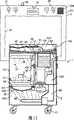
图8是图1中所示的多用途零件水清洗机处于打开构造时的后部透视图,其中安全盖闭合,并带有贮槽中元件的阴影图。8 is a rear perspective view of the multipurpose aqueous parts washer shown in FIG. 1 in an open configuration with the safety cover closed and with shadowed views of components in the sump.
图9是图8的多用途零件水清洗机不带阴影图的后部透视图。FIG. 9 is a rear perspective view, without shadow, of the multipurpose aqueous parts washer of FIG. 8 .
图10是具有V形碎屑盘的图1的多用途零件水清洗机处于所述构造并如图2所示沿着线4-4的侧视图。10 is a side view of the multipurpose aqueous parts washer of FIG. 1 with a V-shaped debris pan in the described configuration and as shown in FIG. 2 along line 4-4.
图11是配备有V形板的图1的多用途零件水清洗机处于闭合构造时其内部不同元件的示意图。Figure 11 is a schematic view of the various elements inside the multipurpose aqueous parts washer of Figure 1 equipped with V-shaped plates in a closed configuration.
具体实施方式Detailed ways
图1是根据本公开的一个实施例的多用途零件水清洗机的部分分解透视图,其中手动清洗部处于打开构造(configuration),并且可拉出架示出为部分移出。图1示出用于清洗零件的设备1,该设备具有由第一清洗腔102和第二清洗腔101限定的自动清洗部2。在一个实施例中,所述用于清洗零件的设备1包括通过一系列枢轴点23可运动地连接到自动清洗部2上的手动清洗部103。1 is a partially exploded perspective view of a multi-purpose aqueous parts washer according to one embodiment of the present disclosure, with the manual wash section in an open configuration and the pull-out rack shown partially removed. FIG. 1 shows a
在一个实施例中,所述用于清洗零件的设备1包括两个不同的清洗腔101、102和一个清洗部103,当面对不同的清洗需要时,它们各自可以由操作者操作。每个腔或部101、102和103优选共用每个腔或部101、102和103共有的并收集在单个储液部36中的清洗液100。本领域普通技术人员应该理解的是,当三个不同的腔或部101、102、103示出为处于某一空间分布时,应该想到的是使用以任何空间布局布置的腔和部。例如,本领域普通技术人员认识到,当用于清洗零件的设备1示出为以类似于车间工具箱形状的竖直堆叠箱时,所述用于清洗零件的设备1可以放置在具有不同空间限制的多个其它位置,所述空间限制包括但不限于需要将装置连接到顶棚、顶壁架、底壁架,或安装在工作台面或工作架上,或插入车辆的一部分中,位于滑动或旋转门内,在工具存储装置上,或者甚至在维护车辆外部。对于每个这些和其它的使用,应该想到的是,以不改变本公开的广泛变化的可能构造来布置和再定向所述腔和部101、102和103。In one embodiment, the
使用者可以使用所述用于清洗零件的设备1,以在部101、102、103之一中清洗单个零件或多个零件。在另一个实施例中,多个零件可以在不同的部101、102、103中同时清洗。应该想到的是一种使用用于清洗零件的设备1来清洗多个零件的方法,其中,第一步,将待清洗的第一零件置于自动清洗部2内,然后将第二零件置于搅拌槽,例如第二清洗腔101内。然后在将待清洗的第三零件置于手动清洗部103之前,将清洗部103关闭。最后,在所述方法中,如后面所述那样致动泵79,以清洗置于不同清洗部101、102、103中的第一、第二和第三零件。在另一个实施例中,仅仅在至少两个零件置于至少两个不同清洗部101、102、103中之后致动泵79。A user can use the device for cleaning
还应该想到的是,根据与用于清洗零件的设备1的特殊型号相关的市场的不同需要使用不同大小和几何形状的每个腔或部101、102和103。作为与图1-8中所示的实施例相关的例子,如果本公开适用于快速汽车组的运动的维护车辆的底盘并且具有对大零件的浸泡清洗的特定需要时,更大的第二腔101可以沿着与第一腔具有相同大小和形状的第一腔102的侧边放置,而手动清洗部103可以位于腔101、102中的一个或两个之上。It is also conceivable that each chamber or
在图1所示的一个实施例中,手动清洗部103由图7所示的贮槽104限定,所述贮槽优选由折叠或弯曲的金属板106制成,所述金属板最好在图5中示出并且具有置于金属板106之上的耐久聚合物或乙烯覆盖层105。在一个实施例中,为了容易地移除和替换,聚合物覆盖层105不与金属板106附连,而是保持在围绕边缘和排液口46的位置。本领域普通技术人员应该理解的是,金属板106之上的覆盖层105用作机械防护物和化学防护物,所述覆盖层105可以移除或由任何其它合适的层状防护物替换,包括但不限于涂料、表面涂层,或者甚至是移除聚合物覆盖层105而由具有类似抛光玻璃的表面的金属板106替换。本领域普通技术人员还应该理解的是,可以使用任何其它类型的防护物,这些防护物设计用于经受与将待清洗的零件置于贮槽104内相关的冲击,并能够化学地经受任何与设备1中使用的清洗液100相关的磨蚀、腐蚀或降解。In one embodiment shown in FIG. 1, the
在一个实施例中,金属板106可以由折叠成开口U形或V形的板47制成,其中略微倾斜的侧壁布置成与V形端壁45相对,以通过重力将废液收集在贮槽104内。所述贮槽104还可以包括一系列位于贮槽104外周上的向内轧制的唇129,以限制和控制飞溅。尽管示出了向内轧制的唇129,但是应该想到的是在贮槽104外周上使用任何几何形状或使用锁定就位的防护装置、防溅装置或防护物,以便为操作者提供任何相似的防护。还应该想到的是使用设计用于防止飞溅的位于贮槽104底部的垫、棉纸或其它材料。In one embodiment, the
图3示出金属板106底部上的底部排液口46。所述排液口46允许传送喷射在贮槽104内的清洗液100并通过排液口46向下收集到第一清洗腔102中。用于设备1中的清洗液100通过由操作者直接手动操作或借助工具和手套操作的流体分配装置49而被释放。图3和8示出具有第一可能中心应变110的底部排液口46。图1-2和4-5示出底部排液口46的底侧。在一个公开的实施例中,后防溅板17示出为由竖直杆附连在与排液口46底部距离小距离的位置处。所述后防溅板17用于防止来自第一清洗腔102的清洗液100流到贮槽104中。尽管示出了作为后防溅板17的一类装置,但是应该想到的是使用在第一清洗腔102的操作过程中能够防止清洗液100向上运动回贮槽104的任何液流位移系统(flow displacement system)。FIG. 3 shows the
在另一个实施例中,贮槽104的底部表面形成盖106,以便当所述盖106如图3所示置于闭合位置时关闭第一清洗腔102。所述盖106也可以借助枢轴点23旋转到如图1所示的打开位置,以允许进入第一清洗腔102。在一个实施例中,贮槽104可以通过两个侧面活塞31保持处于打开构造,所述两个侧面活塞由附连于自动清洗区2的外表面和贮槽104的两个互连部分制成。图1示出活塞31处于伸出位置,而图3示出活塞31处于收回位置。本领域普通技术人员应该理解的是,尽管示出了一种类型的保持装置,但是应该想到的是使用能够分别在如图1和3所示的打开位置和闭合位置之间操作贮槽104的任何锁定或非锁定保持装置。In another embodiment, the bottom surface of the
图8还示出了在自动清洗区2的与图1所示的元件30一起协力操作的锁定装置13,用于将用作盖106的贮槽104锁定到如图3所示的闭合构造。机械接近检测器(未示出)与或不与对应部分表面的操作允许控制系统(在后面完整描述)认知盖106是否打开、闭合或半开。在一个实施例中,检测器为锁定装置13的一部分。在一个想到的实施例中,如果盖106处于打开位置,控制系统关闭所有操作周期或来自泵79的液流,以防止任何清洗液100喷溅或飞溅到操作者。本领域普通技术人员认识到,尽管一种类型的接近检测器置于锁定装置13中,但是可以想到任何类型的接近传感器,其包括但不限于置于盖106后部的铰链23中的弯度检测器、激光检测器、置于自动清洁部2顶部的表面检测器、在盖106的底面上的插入物进入第一清洗腔102的机械检测器等。还应该想到的是使用任何其它类型的锁定机构13、30,所述锁定机构设计成用于固定自动清洗区2上处于任何可能构造的贮槽104、盖106或自动清洗区2,所述锁定机构包括但不限于位于两个侧面活塞31内的锁定机构。FIG. 8 also shows locking means 13 cooperating with
在一个实施例中,图1示出具有壁防护板4的设备,所述壁防护板4设计用于容纳处于打开构造时的贮槽104,并且当操作者在手动清洗部103中正清洗零件时用于保持不同工具和有用物品。应该想到的是使用置于壁防护板4前面24上的一系列钩21、22、灯20、板架19或网架128。置于壁防护板4上的不同元件的目的是在操作的不同阶段为设备1的操作者的使用和操作提供方便。图1示出在15处附连在自动清洗区2两侧的壁防护板4。在图3所示的另一个实施例中,壁防护板4包括锁定机构416,例如一个能够接收第二端或在一个实施例中的钩415或挂钩414的孔。如图5和9所示,所述挂钩414在第一端还附连到安全盖412上。所述安全盖412枢转地在413处附连到手动清洗部103的顶部。所述安全盖可以如图5所示被置于打开构造以便进入工作区,也可以如图8所示被置于闭合构造以便限制进入工作区。在图5中,所述安全盖由挂钩414保持处于打开构造,在该打开构造中,当可熔连接物411被热触发时,热触发可熔连接物411能够将安全盖412从打开构造释放到闭合构造。本领域普通技术人员将认识到,该安全系统设计为当设备1中出现火或热时起作用,以允许热上升到以这样的方式校准的可熔连接物411,使得在这样的熔点闭合手动清洗部103上的安全盖412。所示的安全盖能够限制设备1内的燃料燃烧的氧气供应。该描述的特征称为主动安全装置,其提高了如果在不安全操作条件下设备1的安全条件。所述主动安全装置采用重力作为原动力,使安全盖412从打开构造运动到闭合构造。应该想到的是使用与设备协力实施的任何主动安全装置,例如使用改变设备1构造的其它装置或系统,例如但不限于能够改变条件并使装置回到安全条件的发泡系统或化学释放系统。图5示出连接到挂钩一端并连接到安全盖412内表面的火触发可熔连接物411。还可以想到的是使用例如磁体、夹子、拉环或弹簧这些与挂钩414的第二端协力使用的任何锁定机构。In one embodiment, Figure 1 shows the apparatus with a
还示出的是使用置于自动清洗区2下方、为设备1提供水平活动性的滚轮11或轮。还应该想到(但是没有示出)的是使用用于将设备1稳定在专门位置上的手动锁定轮或垫。还应该想到(但是没有示出)的是使用稳定重物,该稳定重物用作抗衡物或用于减小由于置于自动清洗区2中的运动元件而在储液部36内清洗液100中引起的任何随之发生的波动。同样应该想到并在此公开的是其它减震技术,例如在储液部36中使用压载物(未示出),以减小储液部36中因运动元件或内部运动元件的旋转过程中的泵动效应79引起的运动。Also shown is the use of
还应该想到的是使用如图4所示的位于贮槽104中的保持和存储表面111,所述保持和存储表面用于辅助操作者并且允许一旦零件被清洗并放置在存储表面111上时来自零件的清洗液100的液流。在一个实施例中,所述存储表面111由穿孔的金属制成并附连到V形端壁45上。尽管示出了一种可能类型的存储表面111,但是应该想到的是任何类型的能够用作在贮槽104中清洗过的零件的放置地方的壁架、隆脊、杆、轴、支撑装置等。所述贮槽104还进一步包括手柄18或抓握机构,所述手柄或抓握机构设计为允许操作者将贮槽104从第一构造运动到第二构造(两个构造如图1和3所示)。如图4-5的左视图和右视图所示,贮槽104具有前向角50,形成比前壁更高的后壁,其中手柄18位于贮槽104的前面。本领域普通技术人员将认识到,这样的几何结构,例如那些在公开的可能实施例中所示的几何结构在功能上是有用的,但是决不限制所想到的方案的范围,并且可以根据任何特定类型的用于清洗零件的设备1的功能要求而适用所述几何结构。It should also be contemplated to use a holding and
在一个可能的实施例中,位于贮槽104中的流体分配装置49由如图1所示的软管上的U形连接件25支撑在贮槽104的底侧上。在一个实施例中,所述软管分成两个平行部分54、107,每个部分包括分别位于所述部分54、107上游的手动控制阀51、52,每个部分具有下游的手动清洁工具,例如快速连接管48或设计有刷端部42的流通刷(flow-thru brush)43。手动清洗部103由操作者通过下述步骤操作:将待清洗的机械零件置于贮槽104内,然后用一只手握持任意一个部分54、107和相应的手动清洗工具,从而打开与操作者握持的部分54、107相应的手动控制阀51、52,以引导清洗液100流动到零件上。所示的手动控制阀51、52是手动致动的液流调节器(flow regulator)。尽管示出了手动控制阀51、52,但是应该想到的是使用任何手动控制或电控制的液流控制装置,以将液流维持在用于零件冲洗的合适的速度和压力下。还应该想到的是使用脉动液流。In one possible embodiment, the
图2以部分透明视图示出具有位于储液部36之上的喷射部108的第一清洗腔102。所述储液部36构造用于存储和收集清洗液100和收集碎屑。所述喷射部包括如图7所示的零件支撑装置41和所示的具有至少一个用于将清洗液100分配到零件(未示出)上的喷孔37的喷射杆38。如图2所示的喷射杆38的形状制成为具有顶平面26和底平面40,每个平面具有朝向喷射部108中间部分定向的喷孔37,以用于喷射置于所述部内的任何零件。所述喷射杆38还包括位于顶平面26和底平面40之间的垂直部分。FIG. 2 shows the
图2示出了第二杆喷孔37分布的可能构造。图7示出了如虚线所示的小射流的清洗液100从底平面40和顶平面26射到喷射部108上。图7示出了图1透视图中所示的可拉出架7,所述可拉出架为带有手柄16的架的形式,具有边缘35,置于喷射部108中并具有中间栅格状网状物34。置于喷射部108内的零件(未示出)被来自顶部和底部的清洗液100喷射。所述喷射杆38包括与零件支撑装置和底平面40相邻布置的第一部分和与喷射部108的顶端和顶平面26相邻布置的第二部分。FIG. 2 shows a possible configuration of the distribution of the nozzle holes 37 in the second rod. FIG. 7 shows a small jet of cleaning
在图7所示的一个实施例中,第一清洗腔102包括位于喷射部108和储液部36之间的碎屑收集盘420。所述碎屑收集盘420包括带有多个孔的底面板。在一个实施例中,所述碎屑收集盘420由金属制成并具有平的底板。在图10-11所示的另一个实施例中,所述碎屑收集盘420具有V形底板并配备有手柄421。在优选实施例中,底板由1/16”厚的穿孔的金属板在中间冲压成V形制成。应该想到的是使用穿孔,以便在操作者往储液部36中充注清洗液100时提供视觉引导。操作者将充注储液部36直到在碎屑收集盘420的下端能够看到清洗液100,这表明碎屑收集盘420下方的整个容积已经充满了清洗液。在另一个实施例中,通过在储液部36内表面上制成的可视标记为操作者在充注储液部36的全部步骤中提供引导。尽管在图4、7和图10-11中示出了碎屑盘420的两种不同构造,但是应该想到的是使用由能够存储第一清洗部102环境中的碎屑的任何材料制成的不同的碎屑收集容器。In one embodiment shown in FIG. 7 , the
在又一个实施例中,如图7所示,穿孔板和侧边缘与第一清洗部102可移除地接触。本领域普通技术人员将认识到,第一清洗部102下方的碎屑收集能够以多种方式、使用多种技术、多种形状、不同网状物、材料和固定方法的盘进行。所述碎屑收集盘420必须能够允许清洗液100无阻碍地从喷射部108流到储液部36,即使有碎屑位于碎屑收集盘420的底面板上。碎屑收集盘420的清洁可以采用多种技术和方法进行。应该想到的是,当装置从顶部打开时,可手动取出碎屑收集盘420。还应该想到的是,将滑动门插在清洗腔102的外壳上,以允许从侧面抽出碎屑收集盘420。还应该想到和公开的是,使用用于握持和移除碎屑收集盘420的手柄。In yet another embodiment, as shown in FIG. 7 , the perforated plate and the side edges are in removable contact with the
应该想到的是使用如下装置:不同大小、构造和定向的孔、管和支撑装置,以使得能够根据清洗条件对零件进行充分清洗,所述清洗条件例如但不限于温度、压力、流量以及清洗液100的稀释能力。还应该想到的是使用格栅,所述格栅直接固定到喷射部108内的侧壁上,用于水平支撑和保持设备1内的零件。本领域普通技术人员将认识到,尽管示出矩形几何形状的喷射部108,但是应该想到的是具有任何几何形状的喷射部108。还应该想到的是使用可以用于保持设备1内的零件或者保持其它零件或架的钩、缆线、导轨、边缘或板。It is conceivable to use devices of different sizes, configurations and orientations of holes, tubes and supports to enable adequate cleaning of parts according to cleaning conditions such as but not limited to temperature, pressure, flow and cleaning
在一个实施例中,第二清洗部101可以是矩形几何形状的搅拌槽,该搅拌槽设计用于将待清洗的机械零件保持在清洗液100的搅动液流中。在一个想到的实施例中,可以添加清洗液100的一系列喷射操作,以在搅拌槽内提供额外的清洗。图2所示的连接件39与喷射杆38流体连通,并允许清洗液100流到搅拌槽的底部。所述搅拌槽包括顶部开口和底部入口427,用于使清洗液100从搅拌槽底部入口427向上循环到搅拌槽的顶部并通过顶部开口。在一个实施例中示出了用于引导流体通过顶部开口的槽口,但是本领域普通技术人员应该理解的是,还应该想到在顶部开口之上的溢流。应该想到的是连接到入口427的三通阀,所述三通阀的第一开口连接到底部入口427,第二开口连接到喷射杆38,并且第三开口与第一清洗腔102连通。所述三通阀还可以包括手动选择器,所述手动选择器具有第一定向和第二定向,在所述第一定向上,第一和第二开口流体连通以使清洗液在搅拌槽中循环,在所述第二定向上,第一和第三开口流体连通以将清洗液100从搅拌槽排入第一清洗部102。In one embodiment, the
在一个实施例中,为了稀释清洗液100中碎屑的任何悬浮颗粒,通过使清洗液100持续溢流回到储液部36中,使得流体是持续的并允许搅拌槽内的清洗液100的表面更新。本领域普通技术人员将认识到,应该想到的在第二清洗腔101内进行流体再生的其它方法是,例如搅拌槽底部的排放阀,校准以维持搅拌槽中清洗液100液位的、用作底部排液口的压敏控制流量阀,使用如篮子等用于将清洗液100注回储液部36的可移除的容器。可以使用如图2所示的槽口247,以便于从第二清洗腔101到第一清洗腔102的流动。In one embodiment, in order to dilute any suspended particles of debris in the
所示的第二清洗腔101与第一清洗腔102相邻布置,并带有与自动清洗部2的顶部表面连通的顶部开口。这样由操作者简单地通过握持手柄18而将盖106置于打开构造,就允许容易地进入,并允许进入第一清洗腔102和第二清洗腔101。尽管示出的是进入的一个可能的方法,但是应该想到的是第二清洗腔101可以被置于自动清洗部2中的任何明智的位置,包括但不限于放置在架、隆起、外壳或其它能够布置成与第一清洗部102流体连通的物体中。还应该想到的是使用篮子、慢动(slow-acting)刷或其它能提高搅拌槽清洁能力的运动部件。还应该想到的是在第二清洗腔内使用其它清洗方法,所述清洗方法包括但不限于超声清洗。图1还公开了使用在维护过程中用于排空储液部36的底部排液口12。The shown
用于清洗零件的设备1还包括具有元件部56和控制部121的热能源120,所述热能源置于储液部36中并邻近清洗液100,以用于控制清洗液100的温度。因为用于清洗零件的设备1全部采用单一的清洗液100,所以清洗液100由位于储液部36中的单一元件部56加热到操作温度。在一个实施例中,流体被加热到120

还应该想到的是使用热传感器(未示出),该热传感器布置成与清洗液100连通,以便通过选择性地打开和关闭热能源120来调节清洗液100的温度。在又一个实施例中,温度调节由操作者在显示装置6上使用温度选择钮(未示出)来选择。尽管示出了一种可能的温度控制装置,但是应该想到的是使用清洗液100的任何温度调节方法,所述方法采用单一源、分散源或多个源。还应该想到的是可以根据清洗液100的最佳温度将热源120校准到其它操作和平衡温度。还应该想到的是使用两个不同的能量源,第一个能量源用于根据手动清洗操作过程中的最佳操作温度将清洗液100加热到第一操作温度,第二加热源在将清洗液喷射到位于喷射部108内的零件上之前局部加热清洗液。在一个实施例中,倾斜壁置于隔室80和储液部36之间的分隔壁上。It is also conceivable to use a thermal sensor (not shown) placed in communication with the
所述用于清洗零件的设备1还包括布置成与储液部36中的清洗液100流体连通的泵79。图5示出的泵79具有固定板71和为泵79提供能量的马达70。在一个实施例中,泵79置于储液部36中,并与喷射杆38、搅拌槽101和流体分配装置49流体连通,以便使清洗液100从储液部36循环到搅拌槽101、流通分配装置49或喷射杆38中的至少一个。所述泵马达70置于外壳125中,由如图8所示的侧门124的防护。所述泵79将清洗液100推动到用于清洗零件的设备1的其它部分。在一个实施例中,所述储液部36具有高达20加仑的容积。The
所述用于清洗零件的设备1还包括用于控制上述装置的控制系统200,更具体地包括:自动清洗部2,其由第一清洗腔102限定,包括喷射部108和储液部36,所述喷射部108具有零件支撑装置41和喷射杆38,所述喷射杆38具有至少一个用于将清洗液100分配到零件(未示出)的喷孔,所述储液部36构造用于存储和收集清洗液100;手动清洗部103,其通过枢轴点23可运动地连接到自动清洗部2上,并由包括排液口46和流体分配装置49的贮槽104限定,其中所述流体分配装置49将清洗液100排出到贮槽104中,以便通过排液口46收集到第一清洗腔102中;和插头5,其适于在27处电连接到外部电源,以使用于选择地致动位于自动清洗部2中的至少一个定时器7的控制器201、位于自动清洗部2和手动清洗部103之间的接近检测器(未示出)、与储液部36中的清洗液100接触的热能源56、置于储液部36中的泵79通电,所述泵与喷射杆38和流体分配装置49流体连通,以便使清洗液100从储液部36循环到流体分配装置49或喷射杆38中的至少一个。所述控制器201进一步在泵79被通电时使第一显示装置32通电,在储液部36中的清洁流体低于固定液位时使第二显示装置通电,在热能源56为清洗液100提供能量时使第三显示装置通电。The equipment 1 for cleaning parts also includes a control system 200 for controlling the above-mentioned devices, more specifically: an automatic cleaning part 2, which is defined by the first cleaning chamber 102, includes a spray part 108 and a liquid storage part 36, The spray part 108 has a part support device 41 and a spray rod 38 having at least one spray hole for distributing cleaning fluid 100 to parts (not shown), the liquid reservoir 36 is configured for Storage and collection of cleaning fluid 100; manual cleaning part 103, which is movably connected to automatic cleaning part 2 by pivot point 23, and is defined by a sump 104 comprising a drain 46 and a fluid distribution device 49, wherein the Fluid distribution means 49 discharges cleaning fluid 100 into sump 104 for collection into first cleaning chamber 102 through drain 46; and plug 5 adapted to be electrically connected at 27 to an external power source for selection Actuate the controller 201 of at least one timer 7 located in the automatic cleaning part 2, the proximity detector (not shown) between the automatic cleaning part 2 and the manual cleaning part 103, and the cleaning in the liquid storage part 36 The thermal energy source 56 contacted by the liquid 100 energizes the pump 79 located in the liquid reservoir 36 in fluid communication with the spray bar 38 and the fluid distribution device 49 to circulate the cleaning liquid 100 from the liquid reservoir 36 to the fluid distribution device 49 or at least one of the spray bar 38. The controller 201 further energizes the
所公开的是使用由示出为插头5的能量输入装置使之通电的控制系统200,所述插头5具有带地线的电连接件27(三端插头)。还应该想到的是装置接地,以及使用具有没有地线的电连接件27的插头5。所述插头5可以绕着支撑装置130卷起,如图8所示。在一个实施例中,具有水检测器78的水位检测器77连接到控制系统200。所述液位检测器77用于防止泵79在空气中运转而不是浸没在清洗液100中运转时因为过热而受损。在另一个实施例中,所示的液位检测器直接连接到泵79。Disclosed is the use of a control system 200 energized by an energy input device shown as a plug 5 having an
在一个实施例中,控制系统200由操作者通过显示装置6而操作,其中绿灯是带旋转开/关开关的第一显示装置127,第二显示装置32是黄灯用于监控加热元件,而第三显示装置123是红灯用于监控水位。在一个实施例中,使用者顺时针转动定时器7到所需的时间段。在另一个实施例中,定时器7设定为四分之一小时。还示出的是使用接地故障电路断流器(Ground Fault Circuit Interrupter)(GFCI)式断路器8,其置于防护板下面并且位于显示装置6内。所述断路器允许使用者在过程中断时重置装置,所述过程中断例如但不限于元件故障或液位检测器77不能检测储液部36内的清洗液100或短路。In one embodiment, the control system 200 is operated by the operator through the
本领域普通技术人员应该理解的是,尽管已经结合特定实施例对本公开的教导进行了说明,但是无意于将本发明限定于这些实施例。相反,本申请的发明意欲覆盖完全落入本公开教导范围之内的所有变型和实施例。It will be appreciated by those of ordinary skill in the art that although the teachings of the present disclosure have been described in conjunction with specific embodiments, there is no intent to limit the invention to those embodiments. On the contrary, the invention of the present application is intended to cover all modifications and embodiments that fall within the teaching scope of the present disclosure.
Claims (29)
Translated fromChineseApplications Claiming Priority (4)
| Application Number | Priority Date | Filing Date | Title |
|---|---|---|---|
| US11/681,652 | 2007-03-02 | ||
| US11/681,652US8220471B2 (en) | 2007-03-02 | 2007-03-02 | Multipurpose aqueous parts washer |
| US11/766,643 | 2007-06-21 | ||
| US11/766,643US20080210260A1 (en) | 2007-03-02 | 2007-06-21 | Multipurpose Aqueous Parts Washer |
Related Child Applications (1)
| Application Number | Title | Priority Date | Filing Date |
|---|---|---|---|
| CN2012105686850ADivisionCN103028561A (en) | 2007-03-02 | 2008-02-29 | Multipurpose aqueous parts washer and process |
Publications (2)
| Publication Number | Publication Date |
|---|---|
| CN101254503A CN101254503A (en) | 2008-09-03 |
| CN101254503Btrue CN101254503B (en) | 2013-01-23 |
Family
ID=39732246
Family Applications (1)
| Application Number | Title | Priority Date | Filing Date |
|---|---|---|---|
| CN2008100822570AExpired - Fee RelatedCN101254503B (en) | 2007-03-02 | 2008-02-29 | Multipurpose Parts Water Washer |
Country Status (3)
| Country | Link |
|---|---|
| US (2) | US8220471B2 (en) |
| CN (1) | CN101254503B (en) |
| ES (1) | ES2365775T3 (en) |
Families Citing this family (28)
| Publication number | Priority date | Publication date | Assignee | Title |
|---|---|---|---|---|
| US8297291B1 (en) | 2003-09-09 | 2012-10-30 | Heritage-Crystal Clean, Llc | Combination parts washer and sink washer |
| US8763619B2 (en)* | 2003-09-09 | 2014-07-01 | Heritage-Crystal Clean, Llc | Combination agitating parts washer and sink washer |
| US20100018909A1 (en)* | 2008-07-22 | 2010-01-28 | Smith Jeffrey D | Vibrating screen |
| US9352362B1 (en)* | 2009-10-30 | 2016-05-31 | Alliance Manufacturing, Inc. | Combination spray and immersion parts washer |
| USD619311S1 (en)* | 2009-11-02 | 2010-07-06 | Safety-Kleen Systems, Inc. | Multi-purpose parts washer with stainless steel plate |
| US20110214698A1 (en)* | 2010-03-03 | 2011-09-08 | Fountain Industries | Parts washer |
| CN102343341A (en)* | 2011-08-11 | 2012-02-08 | 华尔润玻璃产业股份有限公司 | Device and method for cleaning gas valve of coal gas pressurizing machine |
| CN102500568A (en)* | 2011-12-29 | 2012-06-20 | 莱顿汽车部件(苏州)有限公司 | Split cleaning vehicle for unidirectional coupler of generator |
| CN103143527A (en)* | 2013-02-20 | 2013-06-12 | 轻工业钟表研究所 | Full-automatic watch cleaning machine |
| KR102109747B1 (en)* | 2013-12-24 | 2020-05-12 | 엘지전자 주식회사 | Multifunctional cleaner unit |
| US10953439B2 (en)* | 2014-01-19 | 2021-03-23 | Gregory Abdul-Ali | Portable overnight degreasing system and method of use |
| CN104492751B (en)* | 2014-12-30 | 2016-06-29 | 桂林电子科技大学 | A kind of ring mould automatic cleaning apparatus |
| US9878498B2 (en)* | 2015-05-04 | 2018-01-30 | Phoenix Analysis And Design Technologies, Inc. | Method and apparatus for removing support material |
| US20160354813A1 (en)* | 2015-06-04 | 2016-12-08 | Arrow Pin & Products Inc. | Apparatus and Method for Cleaning Devices Internally Through Their Ports |
| CN107159669A (en)* | 2015-06-19 | 2017-09-15 | 合肥智慧龙图腾知识产权股份有限公司 | A kind of depainting tool |
| CN105057261A (en)* | 2015-08-27 | 2015-11-18 | 天津佰金隆金属制品有限公司 | Water washing device of copper plating production line |
| CN109414733A (en) | 2016-05-23 | 2019-03-01 | 罗波沃什公司 | For cleaning the device and method of machine |
| CN106269655A (en)* | 2016-09-28 | 2017-01-04 | 无锡市明骥智能机械有限公司 | Cleaning workpiece board for putting |
| US10744538B2 (en) | 2016-12-13 | 2020-08-18 | Robowash Pty Ltd. | Apparatus and method for cleaning industrial parts |
| EP3731972A4 (en)* | 2017-12-31 | 2021-08-25 | PostProcess Technologies Inc. | Method and apparatus for support removal using directed atomized and semi-atomized fluid |
| CN108787558B (en)* | 2018-04-26 | 2020-05-01 | 云南龙帜环境工程有限公司 | Chemistry online cleaning system |
| CN108906755A (en)* | 2018-07-11 | 2018-11-30 | 芜湖博康汽车饰件有限公司 | One kind being used for automobile parts electrophoretic paint processing unit and method |
| CN108971111A (en)* | 2018-07-26 | 2018-12-11 | 芜湖慧宇商贸有限公司 | Car transmission gear detection device |
| US11534803B2 (en)* | 2018-09-07 | 2022-12-27 | Cleaning Technologies Group Llc | Ultrasonic washing cabinet |
| US10882084B2 (en)* | 2018-11-15 | 2021-01-05 | Joes Holdings Llc | Shielded containment cabinet and method of use |
| CN112317373B (en)* | 2020-10-15 | 2021-09-21 | 陇东学院 | Part cleaning device for machining |
| CN112544680A (en)* | 2020-12-11 | 2021-03-26 | 寿县如今食品有限责任公司 | Soaking device convenient for lobster cleaning |
| US12403582B2 (en)* | 2021-01-04 | 2025-09-02 | The Boeing Company | Housing assembly for selectively receiving a part and a method of removing particles from a frictional surface of a pad |
Citations (5)
| Publication number | Priority date | Publication date | Assignee | Title |
|---|---|---|---|---|
| CN87204756U (en)* | 1987-11-10 | 1988-09-28 | 湖南省机械研究所 | Cleaning machine for mechanical part |
| CN2037267U (en)* | 1988-10-14 | 1989-05-10 | 国营威海海林汽车修配厂 | Cleaning machine for spares |
| US5398708A (en)* | 1993-04-16 | 1995-03-21 | Sheldon; Morris W. | Parts cleaning machine |
| CN1167517C (en)* | 1994-09-30 | 2004-09-22 | 楚莫国际有限公司 | Microbial part cleaning system, cleaning device, controller and conversion kit |
| EP1602412A1 (en)* | 2004-06-03 | 2005-12-07 | Rosauto S.r.l. | Washing device equipped with separate automatic and manual washing zones for spray guns and their components |
Family Cites Families (65)
| Publication number | Priority date | Publication date | Assignee | Title |
|---|---|---|---|---|
| US1395728A (en) | 1921-03-09 | 1921-11-01 | Norman A Ormes | Barrel-cleat |
| US1617021A (en) | 1921-10-08 | 1927-02-08 | Robert B Mitchell | Dishwashing machine |
| US1525756A (en) | 1922-10-18 | 1925-02-10 | Albion T Mckenney | Dishwashing machine |
| GB222306A (en) | 1923-09-13 | 1924-10-02 | Heinrch Reist | Improvements in and relating to machines for washing plates dishes and like table utensils |
| US1597267A (en) | 1925-03-30 | 1926-08-24 | Clairmont Adolfo De | Decarbonizing and lubricating device |
| US1691839A (en) | 1925-12-22 | 1928-11-13 | Caskin Langdon | Dishwashing apparatus |
| US1804715A (en) | 1928-03-31 | 1931-05-12 | Standard Sanitary Mfg Co | Combination sink and convertible dishwasher |
| US1889761A (en) | 1929-07-29 | 1932-12-06 | Alfred F Yoerg | Hat cleaning and drying machine |
| BE465428A (en) | 1945-05-04 | |||
| US2651311A (en) | 1945-10-24 | 1953-09-08 | Kewanee Ind Washer Corp | Cleaning apparatus with lubricator therefor |
| US2680802A (en) | 1952-04-12 | 1954-06-08 | Rainbows Inc | Electrical fluid heater |
| US2675012A (en)* | 1952-10-18 | 1954-04-13 | Frank J Scales | Washing apparatus for automotive and machine parts and assmeblies |
| US3115145A (en) | 1960-10-21 | 1963-12-24 | Jr Robert G Monteath | Apparatus for cleaning cooling systems |
| US3026699A (en) | 1961-01-06 | 1962-03-27 | Gen Electric | Washing machine |
| US3439689A (en) | 1966-09-30 | 1969-04-22 | Jet Clean Co | Jet cleaning apparatus with filter means for removing debris from the cleaning fluid |
| US3514330A (en) | 1967-01-09 | 1970-05-26 | Carlson Arthur W | Multi-purpose kitchen unit |
| US3659752A (en) | 1970-03-19 | 1972-05-02 | Adf Ind Inc | Easily removable fluid permeable structure for aerated hopper discharge outlets |
| US3680567A (en)* | 1971-04-28 | 1972-08-01 | William A Hansen | Portable tankless glass washer |
| JPS52309B2 (en)* | 1971-05-15 | 1977-01-06 | ||
| GB1395728A (en) | 1971-12-03 | 1975-05-29 | Wilkins & Mitchell Ltd | Machine with safety device |
| US3960728A (en) | 1975-03-12 | 1976-06-01 | Safety-Kleen Corporation | Disposable filter apparatus |
| US4056114A (en) | 1975-06-03 | 1977-11-01 | Boutillette Arthur A | Parts washer and filter assembly therefor |
| US4103637A (en) | 1975-06-04 | 1978-08-01 | Tridon-Serflex S. A. | Method of shaping a screw type clamping collar |
| US4029115A (en) | 1975-09-03 | 1977-06-14 | Ted Wheeler | Parts washer |
| US4128478A (en) | 1976-06-29 | 1978-12-05 | Metzger Herman U | Parts washer |
| US4048121A (en) | 1977-01-24 | 1977-09-13 | Fremont Industries, Inc. | Low temperature metal cleaning composition |
| US4125119A (en) | 1977-03-25 | 1978-11-14 | Haas Elwood L | High pressure cleaning device |
| US4143669A (en) | 1977-06-10 | 1979-03-13 | The Mart Corporation | Power parts washer |
| US4213475A (en) | 1979-02-05 | 1980-07-22 | Minkin Gary E | Power parts washer |
| US4261378A (en) | 1979-07-19 | 1981-04-14 | Safety-Kleen Corporation | Accessory for parts washer |
| US4561903A (en) | 1981-06-22 | 1985-12-31 | Trigent, Inc. | Method of solvent spray cleaning in an enclosed chamber |
| US4433698A (en) | 1981-06-22 | 1984-02-28 | Trigent, Inc. | High pressure parts washer |
| USD275426S (en) | 1982-03-26 | 1984-09-04 | The Hotsy Corporation | Washer for industrial and automobile parts |
| US4543182A (en) | 1983-04-01 | 1985-09-24 | Solvent Extractors Inc. | Parts washing and/or fluid recovery apparatus |
| US4726388A (en) | 1984-07-13 | 1988-02-23 | Swinehart Lonn L | Automatic vehicle washing equipment |
| US4589158A (en) | 1984-09-19 | 1986-05-20 | Morris Sheldon | Article cleaning device for removing surface contaminants from the article by brushing and liquid contact |
| US4741351A (en) | 1985-03-07 | 1988-05-03 | The Modern Auto Recycling Techniques Corporation | Parts washer |
| US4776359A (en) | 1985-12-09 | 1988-10-11 | Federighi Jr George B | Under counter glass washer |
| US4911190A (en) | 1988-05-18 | 1990-03-27 | Sheldon Morris W | Article cleaning machine for removing surface contaminants from the article |
| USD318098S (en) | 1988-05-31 | 1991-07-09 | The Hotsy Corporation | Valve check member |
| US5368053A (en) | 1991-07-29 | 1994-11-29 | Ransohoff Company | Parts cleaning machine and method of cleaning parts |
| US5232299A (en) | 1992-07-21 | 1993-08-03 | Better Engineering Mfg., Inc. | Parts washer |
| CA2080181C (en) | 1992-08-28 | 2003-06-10 | Robert Edward Reuter | Overhead cabinet with rotating door |
| US5322078A (en) | 1993-02-18 | 1994-06-21 | Kleer-Flo Company | Aqueous parts washing apparatus |
| US5303725A (en) | 1993-02-18 | 1994-04-19 | Kleer-Flo Company | Machine part cleaning apparatus |
| JP2575197Y2 (en) | 1993-05-25 | 1998-06-25 | 李海燮 | Folding sink |
| US5580394A (en) | 1993-07-12 | 1996-12-03 | Airtronic, Inc. | Method for cleaning industrial parts including sequential direct spray and immersion of the part |
| US5464033A (en) | 1994-05-20 | 1995-11-07 | Major Industrial Technology, Inc. | Hot solvent cleaning tank |
| US5528913A (en) | 1994-08-01 | 1996-06-25 | General Electric Company | Washing machine with snubbers for limiting unbalanced load vibration excursions |
| USD370096S (en) | 1994-10-14 | 1996-05-21 | Cuda Corporation | Parts washer |
| US5499643A (en)* | 1995-04-11 | 1996-03-19 | Vincent, Jr.; C. Elmas | Cleaning apparatus for removing oily waste |
| US5640981A (en) | 1995-05-01 | 1997-06-24 | Cuda Corporation | Parts washer |
| USD374316S (en) | 1995-05-01 | 1996-10-01 | Cuda Corporation | Parts washer |
| USD393332S (en) | 1996-08-13 | 1998-04-07 | Richard Nygren | Spray gun washer |
| US6044852A (en) | 1996-09-10 | 2000-04-04 | Landa, Inc. | Parts washer |
| US6109277A (en) | 1996-09-10 | 2000-08-29 | Landa, Inc. | Parts washer |
| US6068707A (en) | 1997-01-15 | 2000-05-30 | Magliocca; Charles T. | Portable parts washing apparatus with centrifugal filter |
| US6124253A (en) | 1997-09-16 | 2000-09-26 | Church & Dwight Co., Inc. | Aqueous composition for low-temperature metal-cleaning and method of use |
| US6115541A (en) | 1997-11-07 | 2000-09-05 | Rhodes; Laurence Mark | Parts washer, and method for making components thereof |
| US6199565B1 (en) | 1998-11-05 | 2001-03-13 | Ronald H. Bluestone | Modular parts washing apparatus and servicing method |
| JP3905320B2 (en) | 2001-02-28 | 2007-04-18 | オリンパス株式会社 | Endoscopic high-temperature high-pressure steam sterilization container and endoscope cleaning and sterilization system |
| US6874512B2 (en)* | 2003-04-10 | 2005-04-05 | Safety-Kleen Systems, Inc. | Parts washer with improved temperature and pump control |
| US7484515B1 (en) | 2003-09-09 | 2009-02-03 | Bluestone Ronald H | Combination parts jet washer and sink washer |
| US7128075B2 (en) | 2003-12-01 | 2006-10-31 | Safety-Kleen Systems, Inc. | Parts washing apparatus |
| US20050199267A1 (en) | 2004-03-15 | 2005-09-15 | Oakes Kenton T. | Washing system using recycled cleaning liquid |
- 2007
- 2007-03-02USUS11/681,652patent/US8220471B2/enactiveActive
- 2008
- 2008-02-18ESES08151579Tpatent/ES2365775T3/enactiveActive
- 2008-02-29CNCN2008100822570Apatent/CN101254503B/ennot_activeExpired - Fee Related
- 2012
- 2012-05-22USUS13/477,533patent/US20120291828A1/ennot_activeAbandoned
Patent Citations (5)
| Publication number | Priority date | Publication date | Assignee | Title |
|---|---|---|---|---|
| CN87204756U (en)* | 1987-11-10 | 1988-09-28 | 湖南省机械研究所 | Cleaning machine for mechanical part |
| CN2037267U (en)* | 1988-10-14 | 1989-05-10 | 国营威海海林汽车修配厂 | Cleaning machine for spares |
| US5398708A (en)* | 1993-04-16 | 1995-03-21 | Sheldon; Morris W. | Parts cleaning machine |
| CN1167517C (en)* | 1994-09-30 | 2004-09-22 | 楚莫国际有限公司 | Microbial part cleaning system, cleaning device, controller and conversion kit |
| EP1602412A1 (en)* | 2004-06-03 | 2005-12-07 | Rosauto S.r.l. | Washing device equipped with separate automatic and manual washing zones for spray guns and their components |
Also Published As
| Publication number | Publication date |
|---|---|
| US20120291828A1 (en) | 2012-11-22 |
| US20080210276A1 (en) | 2008-09-04 |
| US8220471B2 (en) | 2012-07-17 |
| ES2365775T3 (en) | 2011-10-11 |
| CN101254503A (en) | 2008-09-03 |
Similar Documents
| Publication | Publication Date | Title |
|---|---|---|
| CN101254503B (en) | Multipurpose Parts Water Washer | |
| EP1964618B1 (en) | Multipurpose aqueous parts washer and process | |
| US8225804B2 (en) | Multipurpose aqueous parts washer | |
| US7875127B2 (en) | Movable sink parts washer | |
| US5322078A (en) | Aqueous parts washing apparatus | |
| EP2358253B1 (en) | Dishwasher and a water tank adapted for a dishwasher | |
| US7484515B1 (en) | Combination parts jet washer and sink washer | |
| US6109277A (en) | Parts washer | |
| WO2011159559A1 (en) | Combination agitating parts washer and sink washer | |
| US8297291B1 (en) | Combination parts washer and sink washer | |
| US5845661A (en) | Parts washer | |
| CA3075569A1 (en) | Cleaning and fluid distillation apparatus | |
| HK1125890A (en) | Multipurpose aqueous parts washer | |
| JP2006239633A (en) | Strainer washer | |
| EP1419883A1 (en) | Washing apparatus | |
| KR200341818Y1 (en) | Moving type grill cleaner | |
| HK1117788B (en) | Parts washer heater pump module | |
| HK1117788A1 (en) | Parts washer heater pump module | |
| AU1648599A (en) | Article cleaning apparatus |
Legal Events
| Date | Code | Title | Description |
|---|---|---|---|
| C06 | Publication | ||
| PB01 | Publication | ||
| REG | Reference to a national code | Ref country code:HK Ref legal event code:DE Ref document number:1125890 Country of ref document:HK | |
| C10 | Entry into substantive examination | ||
| SE01 | Entry into force of request for substantive examination | ||
| C14 | Grant of patent or utility model | ||
| GR01 | Patent grant | ||
| C56 | Change in the name or address of the patentee | ||
| CP02 | Change in the address of a patent holder | Address after:Massachusetts USA Patentee after:Safety KLEEN Systems Inc. Address before:Texas in the United States Patentee before:Safety KLEEN Systems Inc. | |
| REG | Reference to a national code | Ref country code:HK Ref legal event code:WD Ref document number:1125890 Country of ref document:HK | |
| CF01 | Termination of patent right due to non-payment of annual fee | ||
| CF01 | Termination of patent right due to non-payment of annual fee | Granted publication date:20130123 Termination date:20150229 | |
| EXPY | Termination of patent right or utility model |