CN101247756A - temperature measuring device - Google Patents
temperature measuring deviceDownload PDFInfo
- Publication number
- CN101247756A CN101247756ACNA2005800160141ACN200580016014ACN101247756ACN 101247756 ACN101247756 ACN 101247756ACN A2005800160141 ACNA2005800160141 ACN A2005800160141ACN 200580016014 ACN200580016014 ACN 200580016014ACN 101247756 ACN101247756 ACN 101247756A
- Authority
- CN
- China
- Prior art keywords
- temperature
- contact element
- patch
- reading
- thermal
- Prior art date
- Legal status (The legal status is an assumption and is not a legal conclusion. Google has not performed a legal analysis and makes no representation as to the accuracy of the status listed.)
- Pending
Links
Images


Classifications
- G—PHYSICS
- G01—MEASURING; TESTING
- G01K—MEASURING TEMPERATURE; MEASURING QUANTITY OF HEAT; THERMALLY-SENSITIVE ELEMENTS NOT OTHERWISE PROVIDED FOR
- G01K1/00—Details of thermometers not specially adapted for particular types of thermometer
- G01K1/16—Special arrangements for conducting heat from the object to the sensitive element
- G01K1/165—Special arrangements for conducting heat from the object to the sensitive element for application in zero heat flux sensors
- A—HUMAN NECESSITIES
- A61—MEDICAL OR VETERINARY SCIENCE; HYGIENE
- A61B—DIAGNOSIS; SURGERY; IDENTIFICATION
- A61B5/00—Measuring for diagnostic purposes; Identification of persons
- A61B5/01—Measuring temperature of body parts ; Diagnostic temperature sensing, e.g. for malignant or inflamed tissue
- A—HUMAN NECESSITIES
- A61—MEDICAL OR VETERINARY SCIENCE; HYGIENE
- A61B—DIAGNOSIS; SURGERY; IDENTIFICATION
- A61B5/00—Measuring for diagnostic purposes; Identification of persons
- A61B5/68—Arrangements of detecting, measuring or recording means, e.g. sensors, in relation to patient
- A61B5/6801—Arrangements of detecting, measuring or recording means, e.g. sensors, in relation to patient specially adapted to be attached to or worn on the body surface
- A61B5/683—Means for maintaining contact with the body
- A61B5/6832—Means for maintaining contact with the body using adhesives
- A61B5/6833—Adhesive patches
- G—PHYSICS
- G01—MEASURING; TESTING
- G01K—MEASURING TEMPERATURE; MEASURING QUANTITY OF HEAT; THERMALLY-SENSITIVE ELEMENTS NOT OTHERWISE PROVIDED FOR
- G01K1/00—Details of thermometers not specially adapted for particular types of thermometer
- G01K1/08—Protective devices, e.g. casings
- G—PHYSICS
- G01—MEASURING; TESTING
- G01K—MEASURING TEMPERATURE; MEASURING QUANTITY OF HEAT; THERMALLY-SENSITIVE ELEMENTS NOT OTHERWISE PROVIDED FOR
- G01K1/00—Details of thermometers not specially adapted for particular types of thermometer
- G01K1/16—Special arrangements for conducting heat from the object to the sensitive element
- G—PHYSICS
- G01—MEASURING; TESTING
- G01K—MEASURING TEMPERATURE; MEASURING QUANTITY OF HEAT; THERMALLY-SENSITIVE ELEMENTS NOT OTHERWISE PROVIDED FOR
- G01K1/00—Details of thermometers not specially adapted for particular types of thermometer
- G01K1/20—Compensating for effects of temperature changes other than those to be measured, e.g. changes in ambient temperature
- G—PHYSICS
- G01—MEASURING; TESTING
- G01K—MEASURING TEMPERATURE; MEASURING QUANTITY OF HEAT; THERMALLY-SENSITIVE ELEMENTS NOT OTHERWISE PROVIDED FOR
- G01K13/00—Thermometers specially adapted for specific purposes
- G01K13/20—Clinical contact thermometers for use with humans or animals
Landscapes
- Physics & Mathematics (AREA)
- Health & Medical Sciences (AREA)
- Life Sciences & Earth Sciences (AREA)
- General Physics & Mathematics (AREA)
- Molecular Biology (AREA)
- Surgery (AREA)
- Engineering & Computer Science (AREA)
- Biomedical Technology (AREA)
- Heart & Thoracic Surgery (AREA)
- Medical Informatics (AREA)
- Biophysics (AREA)
- Pathology (AREA)
- Animal Behavior & Ethology (AREA)
- General Health & Medical Sciences (AREA)
- Public Health (AREA)
- Veterinary Medicine (AREA)
- Measuring And Recording Apparatus For Diagnosis (AREA)
- Radiation Pyrometers (AREA)
- Investigating Or Analyzing Materials Using Thermal Means (AREA)
- Measurement Of The Respiration, Hearing Ability, Form, And Blood Characteristics Of Living Organisms (AREA)
Abstract
Description
Translated fromChinese发明领域field of invention
本发明涉及高速、准确的温度测量。更具体地说,本发明涉及通过测量物体表面温度来计算物体内部温度的设备。The present invention relates to high-speed, accurate temperature measurement. More specifically, the present invention relates to devices for calculating the internal temperature of an object by measuring the surface temperature of the object.
背景技术Background technique
物体的内部温度可以通过物体的外表面温度确定,该外表面温度利用基于传导的设备或基于辐射的设备测量。假设被测物体具有内部温度处于相当稳定状态的内部以及外表面。很多情况下希望知道该物体的内部温度。例子:监视保存有危险化学物质的箱子的内部安全等级,确定牲畜是否已经准备好受精,或检查医院里病人的温度。The internal temperature of an object can be determined from the external surface temperature of the object, measured using a conduction-based device or a radiation-based device. It is assumed that the object to be measured has an interior and an exterior surface where the interior temperature is in a relatively stable state. In many cases it is desirable to know the internal temperature of the object. Examples: monitoring the internal security level of boxes holding hazardous chemicals, determining whether livestock is ready to be fertilized, or checking the temperature of patients in a hospital.
本发明说明书的背景部分回顾了作为物体温度测量一般应用的人体温度测量方案,并且描述了现有技术。The background section of the present specification reviews the human body temperature measurement scheme as a general application of object temperature measurement and describes the prior art.
对于基于传导的测量,温度计探针在测量过程中必须与物体一直接触。该温度测量是为了测量物体内部组织的温度,此温度与物体中心温度很接近。该测量设备与外部组织,如皮肤或更理想地,与比较热绝缘的外部组织,如喉咙,相接触。大概需要10分钟才能通过外部组织的对流来使测量装置达到能测量内部组织温度的平衡温度。这么长的测量时间对病人来说不方便。For conduction-based measurements, the thermometer probe must remain in contact with the object during the measurement. This temperature measurement is to measure the temperature of the internal tissue of the object, which is very close to the core temperature of the object. The measuring device is in contact with an external tissue, such as the skin or, more ideally, a relatively thermally insulating external tissue, such as the throat. It takes approximately 10 minutes for the measurement device to reach an equilibrium temperature for measuring the internal tissue temperature by convection from the external tissue. Such a long measurement time is inconvenient for the patient.
可以采用预测算法来缩短测量时间。然而,通常这会导致缩短的测量时间所引起的较低精度的代价。Predictive algorithms can be employed to shorten the measurement time. However, generally this comes at the expense of lower accuracy caused by shortened measurement times.
另一方面,红外(IR)辐射是一种快速测量温度的方法。同样,最精确的测量从保护的外部组织得到,因而红外温度计通常测量鼓膜(耳膜)温度。Infrared (IR) radiation, on the other hand, is a quick way to measure temperature. Also, the most accurate measurements are taken from the protected outer tissue, so infrared thermometers usually measure the temperature of the tympanic membrane (eardrum).
然而,这样的测量被认为是侵入式的,会打扰病人。另外由于耳道不都是直的从而视线不能直接到耳膜,存在一定的局限性。此外,当利用辐射来直接测量皮肤温度,该测量受环境温度影响。However, such measurements are considered invasive and disturbing to the patient. In addition, since the ear canals are not all straight, the line of sight cannot directly reach the eardrum, so there are certain limitations. Furthermore, when using radiation to directly measure skin temperature, the measurement is influenced by the ambient temperature.
传导式测量的一个改进是与病人皮肤持久接触的温度计。由于该持久粘贴的温度计在完成温度测量的时候有足够时间达到热平衡,该方案可以达到高的精确度。An improvement over conductive measurement is a thermometer that is in permanent contact with the patient's skin. Since the permanently attached thermometer has sufficient time to reach thermal equilibrium when the temperature measurement is completed, the solution can achieve high accuracy.
然而,把温度计贴在身体上是有问题的。长时间″戴着″这样的设备对病人,尤其是婴儿来说不方便。However, sticking a thermometer to the body is problematic. "Wearing" such devices for long periods of time is inconvenient for patients, especially infants.
本发明还利用了延长接触达到高精确传导的原理。然而只有无源元件和病人接触(被病人戴着)。实际的测量要么通过红外测量设备从无源传导接触装置读取温度,要么在无源元件包含热传感器情况下通过合适电子设备完成。The present invention also utilizes the principle of extended contact to achieve high precision conduction. However, only the passive components are in contact with (worn by) the patient. The actual measurement is either done by reading the temperature from a passive conductive contact with an infrared measuring device, or by suitable electronics in the case where the passive component contains a thermal sensor.
本发明人早前的发明,美国专利NO.62800397,发明名称为″高速准确的温度测量设备″(2001)中已经确定,从人体,例如从血管到皮肤,散发出的热通量和在皮肤上测量的温度一起可以用来准确得出人体的内部温度。本发明同样涉及在温度测量中利用热通量,然而该分析是在稳态时所做而不是暂态时所做。在稳态时,热通量为常数,并且温度的所有时间派生值为零。因此,可以利用简化的模型来得到内部温度。本发明与早前专利的区别还在于,它读取得的温度所涉及的表面与所测物体的表面持续接触,从而使得内部物体温度的计算更准确。The inventor's earlier invention, U.S. Patent No. 62800397, titled "High-Speed Accurate Temperature Measurement Apparatus" (2001), has determined that the heat flux emanating from the human body, such as from blood vessels to the skin, and in the skin Together with the temperature measured above, it can be used to accurately derive the internal temperature of the human body. The present invention also involves the use of heat flux in temperature measurements, however the analysis is done at steady state rather than transient. At steady state, the heat flux is constant and all time derivatives of temperature are zero. Therefore, a simplified model can be used to obtain the internal temperature. The present invention also differs from the earlier patents in that the surface involved in the read temperature is in continuous contact with the surface of the measured object, thereby making the calculation of the temperature of the internal object more accurate.
总之,本发明的主要目的是提供一种方便,快速,准确测量内部温度的装置。In conclusion, the main purpose of the present invention is to provide a device for convenient, fast and accurate measurement of internal temperature.
看完本说明书及参考附图后可知道本发明的其他目的和优点。Other objects and advantages of the present invention will become apparent after reading this specification and referring to the accompanying drawings.
发明内容Contents of the invention
根据本发明的优选实施例提供了用于非侵入式测量身体内部温度或热阻系数的设备,该身体包括具有相当稳定的内部温度的内部区域和具有表面温度的外表面间的热导媒介,该设备包括:According to a preferred embodiment of the present invention there is provided a device for non-invasively measuring the internal temperature or thermal resistivity of a body comprising a thermally conductive medium between an internal region having a relatively stable internal temperature and an external surface having a surface temperature, The equipment includes:
贴片,包括用于与外表面粘贴的至少一个接触元件和用于尽可能地使接触元件与周围热环境热绝缘的保温外罩;A patch comprising at least one contact element for bonding to an outer surface and an insulating cover for thermally insulating the contact element from the surrounding thermal environment as far as possible;
读取装置,用于读取贴片上的一个或多个热量值;a reading device for reading one or more calorific values on the patch;
处理元件,用于处理所述至少一个或多个热量值,以得到内部区域的内部温度或传导媒介的热阻系数;a processing element for processing said at least one or more heat values to obtain the internal temperature of the internal region or the thermal resistivity of the conduction medium;
另外,根据本发明的另一个优选实施例,在保温外罩和接触元件之间有气体。In addition, according to another preferred embodiment of the present invention, there is gas between the thermal enclosure and the contact element.
另外,根据本发明的另一个优选实施例,所述气体对于红外辐射是透明的。Additionally, according to another preferred embodiment of the present invention, said gas is transparent to infrared radiation.
另外,根据本发明的另一个优选实施例,所述气体为空气。In addition, according to another preferred embodiment of the present invention, the gas is air.
另外,根据本发明的另一个优选实施例,所述保温外罩和接触元件间为真空。In addition, according to another preferred embodiment of the present invention, there is a vacuum between the thermal insulation cover and the contact element.
另外,根据本发明的另一个优选实施例,所述贴片包括多个测量位置中的至少一个,该多个测量位置具有不同测量位置在外表面形成不同的热边界条件的特征。In addition, according to another preferred embodiment of the present invention, the patch includes at least one of a plurality of measurement locations, and the plurality of measurement locations has the feature that different measurement locations form different thermal boundary conditions on the outer surface.
另外,根据本发明的另一个优选实施例,所述贴片包括三个测量位置。In addition, according to another preferred embodiment of the present invention, the patch includes three measurement locations.
另外,根据本发明的另一个优选实施例,所述测量位置的特性为,具有下面这组特性中所选的明显特性:不同的导热性,不同的厚度,或者不同的发射性,从而在外表面形成不同的边界条件。In addition, according to another preferred embodiment of the present invention, the characteristic of the measurement location is to have a significant characteristic selected from the following group of characteristics: different thermal conductivity, different thickness, or different emissivity, so that the outer surface form different boundary conditions.
另外,根据本发明的另一个优选实施例,所述贴片包括多个测量位置中的至少一个,该多个测量位置特征为:每个测量位置形成两个或更多测量点,该测量点在外表面形成不同热边界。In addition, according to another preferred embodiment of the present invention, the patch includes at least one of a plurality of measurement locations, and the plurality of measurement locations is characterized by: each measurement location forms two or more measurement points, and the measurement points Different thermal boundaries are formed on the outer surface.
另外,根据本发明的另一个优选实施例,所述不同的热边界条件的特征为具有包括下组性质中所选显著性质:不同的热导性或不同的厚度。In addition, according to another preferred embodiment of the present invention, the different thermal boundary conditions are characterized by a prominent property selected from the group consisting of: different thermal conductivities or different thicknesses.
另外,根据本发明的另一个优选实施例,所述测量位置被热绝缘隔开。In addition, according to another preferred embodiment of the present invention, the measurement locations are separated by thermal insulation.
另外,根据本发明的另一个优选实施例,所述两个或两个测量点之间隔开一个比相邻测量位置的间隔距离小很多的距离,以消除或者大大减小二维效应。In addition, according to another preferred embodiment of the present invention, the two or two measurement points are separated by a distance much smaller than the distance between adjacent measurement positions, so as to eliminate or greatly reduce the two-dimensional effect.
另外,根据本发明的另一个优选实施例,所述贴片的每个测量位置都配有至少一个热隔离的热或温度传感器,每个传感器都配有到贴片外部终端的引线,读取装置可以与其接触来读数。In addition, according to another preferred embodiment of the present invention, each measurement location of the patch is equipped with at least one thermally isolated heat or temperature sensor, each sensor is equipped with a lead wire to an external terminal of the patch, read The device can be touched to take a reading.
另外,根据本发明的另一个优选实施例,所述读取装置是红外辐射计。In addition, according to another preferred embodiment of the present invention, the reading device is an infrared radiometer.
另外,根据本发明的另一个优选实施例,绝缘外罩上配有接入点,辐射计通过该接入点可以获取一个或多个热量值。In addition, according to another preferred embodiment of the present invention, the insulating housing is provided with an access point through which the radiometer can acquire one or more calorific values.
另外,根据本发明的另一个优选实施例,所述接入点从包括窗口、开口、光栏或快门的组中选择。Additionally, according to another preferred embodiment of the present invention, said access point is selected from the group consisting of a window, an opening, a light barrier or a shutter.
另外,根据本发明的另一个优选实施例,接触元件包括热阻系数和发射率相当低的位置,所述罩子具有低发射率,并且其中罩子足够大,可避免测向热通量,从而使得接触元件的温度在热稳定状态下与内部温度几乎相等。In addition, according to another preferred embodiment of the present invention, the contact element comprises a location of relatively low thermal resistivity and emissivity, said shroud has low emissivity, and wherein the shroud is large enough to avoid directional heat flux such that The temperature of the contact element is almost equal to the internal temperature in a thermally stable state.
另外,根据本发明的另一个优选实施例,所述设备还包括用户界面,从而使得使用者能校准及操作读取装置,并得知所计算的内部温度。In addition, according to another preferred embodiment of the present invention, the device further comprises a user interface enabling the user to calibrate and operate the reading device and to know the calculated internal temperature.
另外,根据本发明的另一个优选实施例,所述用于读取用户信息的装置为条形码阅读器。In addition, according to another preferred embodiment of the present invention, the device for reading user information is a barcode reader.
另外,根据本发明的另一个优选实施例,所述贴片包含病人识别信息。Additionally, according to another preferred embodiment of the present invention, the patch contains patient identification information.
另外,根据本发明的另一个优选实施例,所述接触元件还具有粘贴材料以将接触元件贴到外表面。In addition, according to another preferred embodiment of the present invention, the contact element also has an adhesive material for affixing the contact element to the outer surface.
另外,根据本发明的另一个优选实施例,所述贴片具有至少一个粘贴表面。In addition, according to another preferred embodiment of the present invention, the patch has at least one sticking surface.
另外,根据本发明的另一个优选实施例,所述读取装置具有至另一个用于存储或进一步处理数据的设备的数据通信界面。Furthermore, according to another preferred embodiment of the present invention, the reading device has a data communication interface to another device for storing or further processing the data.
另外,根据本发明的另一个优选实施例,所述处理单元具有一个数据通信界面。In addition, according to another preferred embodiment of the present invention, the processing unit has a data communication interface.
另外,根据本发明的另一个优选实施例,所述贴片还进一步包括用于适当调整读取装置的校准器。In addition, according to another preferred embodiment of the present invention, the patch further includes a calibrator for properly adjusting the reading device.
另外,根据本发明的另一个优选实施例,所述读取装置还包括读取端,其在读取时与贴片相接触,该读取端具有一次性罩子。In addition, according to another preferred embodiment of the present invention, the reading device further includes a reading end, which is in contact with the patch during reading, and the reading end has a disposable cover.
另外,根据本发明的另一个优选实施例,所述读取装置还包括读取端,其在读取时与贴片相接触,该读取端具有一次性罩子。其中所述一次性盖子具有导电涂层,以使贴片的外部终端可电接触。In addition, according to another preferred embodiment of the present invention, the reading device further includes a reading end, which is in contact with the patch during reading, and the reading end has a disposable cover. Wherein the disposable cover has a conductive coating so that the external terminals of the patch can be electrically contacted.
因此,同样根据本发明的一个优选实施例,提供了非侵入性测量身体内部温度或热阻系数的方法,所述身体包括处于温度相当稳定内部的内部区域和具有表面温度的外表面之间的热导介质,所述方法包括:Therefore, also according to a preferred embodiment of the present invention, there is provided a method of non-invasively measuring the temperature or thermal resistivity inside a body comprising an inner region between a relatively stable temperature interior and an outer surface having a surface temperature a thermally conductive medium, the method comprising:
将具有至少一个接触元件和带有接触元件的绝缘外罩的贴片与外表面接触并使得接触元件达到热稳定状态;contacting a patch having at least one contact element and an insulating housing with the contact element to the outer surface and allowing the contact element to reach a thermally stable state;
在使用读取装置的贴片上获取一个或多个热量值;acquiring one or more caloric values on the patch using a reading device;
使用处理单元处理所述至少一个或多个数量值以得到内部区域的内部温度或传导介质的热阻系数;processing said at least one or more quantitative values using a processing unit to obtain an internal temperature of the internal region or a thermal resistivity of the conducting medium;
另外,根据本发明的另一个优选实施例,所述方法包括测量身体的热阻系数。Additionally, according to another preferred embodiment of the present invention, the method includes measuring the thermal resistivity of the body.
另外,根据本发明的另一个优选实施例,所述方法还包括:In addition, according to another preferred embodiment of the present invention, the method further includes:
得出贴片上多个测量位置的热量值。Results in calorific value for multiple measurement locations on the patch.
利用每个位置的关系,解一系列与多个测量位置相关的方程来得到传导介质的内部温度或热阻系数Using the relationship at each location, solve a series of equations related to multiple measurement locations to obtain the internal temperature or thermal resistivity of the conducting medium
其中in
q″K是热导介质的热通量q″K is the heat flux of the thermally conductive medium
Keff是热导介质的有效电导率Keff is the effective electrical conductivity of the thermally conductive medium
ΔX是热导介质的厚度ΔX is the thickness of the thermally conductive medium
Ts是皮肤表面所测得的温度Ts is the temperature measured on the skin surface
Tdeep是内部温度Tdeep is the internal temperature
另外,根据本发明的另一个优选实施例,所述方法还包括:In addition, according to another preferred embodiment of the present invention, the method further includes:
在贴片上的多个测量位置中的不同测量点得到热量值。Calorific values are obtained at different measurement points in a plurality of measurement locations on the patch.
利用每个位置的关系,解一系列涉及多个测量位置的方程来得到传导介质的内部温度及热阻系数Using the relationship at each location, solve a series of equations involving multiple measurement locations to obtain the internal temperature and thermal resistance coefficient of the conducting medium

其中in
q″为热通量q″ is the heat flux
Ksi为i-th位置点S接触元件的传导率Ksi is the conductivity of the i-th position point S contact element
ΔXsi i-th位置点S接触元件的厚度ΔXsi i-th position point S the thickness of the contact element
Tsi是I-th位置点S处接触元件的温度Tsi is the temperature of the contact element at point S of the I-th position
Tci是I-th位置点C处接触元件的温度Tci is the temperature of the contact element at point C of the I-th position
Keff为热导媒介的有效传导率Keff is the effective conductivity of the heat conducting medium
ΔX为热导媒介的厚度ΔX is the thickness of the heat conduction medium
Tdeep是内部温度Tdeep is the internal temperature
另外,根据本发明的另一个优选实施例,所述接触元件包括—个具有十分低的热阻系数的位置,使得其上的温度处于稳态并与内部温度几乎相等。其中得出温度的步骤包括使内部温度与外在温度几乎相等。In addition, according to another preferred embodiment of the present invention, said contact element comprises a location with a sufficiently low thermal resistivity such that the temperature thereon is in a steady state and nearly equal to the internal temperature. Wherein the step of deriving the temperature includes making the internal temperature nearly equal to the external temperature.
另外,根据本发明的另一个优选实施例,得出温度的过程包括从预定的校准表加一个已知的修正值。Additionally, according to another preferred embodiment of the present invention, deriving the temperature includes adding a known correction value from a predetermined calibration table.
另外,根据本发明的另一个优选实施例,所述方法进一步包括反复确定接触元件处的热通量,当热通量相当稳定时指示所述接触元件是否达到稳定状态。Additionally, according to another preferred embodiment of the present invention, the method further comprises iteratively determining the heat flux at the contact element, indicating whether the contact element has reached a steady state when the heat flux is fairly stable.
另外,根据本发明的一个优选实施例,所述方法进一步包括反复确定接触元件处的温度并且指示接触元件在温度相当稳定时是否达到热稳定状态。Additionally, according to a preferred embodiment of the present invention, the method further comprises iteratively determining the temperature at the contact element and indicating whether the contact element has reached a thermally stable state when the temperature is fairly stable.
附图说明:Description of drawings:
本发明仅以示例方式,参考附图,描述于此,其中同样元件以同样的参考数字表示。The present invention is described herein, by way of example only, with reference to the drawings, in which like elements are designated by like reference numerals.
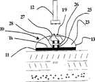
图1表示人体外表面的热通量;Figure 1 shows the heat flux on the outer surface of the human body;
图2为本发明的框图;Fig. 2 is a block diagram of the present invention;
图3A为带有红外辐射读取装置的本发明第一优选实施例截面侧视图;Figure 3A is a cross-sectional side view of the first preferred embodiment of the present invention with an infrared radiation reading device;
图4表示了根据本发明的粘贴在病人上的贴片以及读取装置;Figure 4 shows a patch and a reading device attached to a patient according to the present invention;
图5A为根据本发明第一优选实施例的贴片的截面侧视图;Figure 5A is a cross-sectional side view of a patch according to a first preferred embodiment of the present invention;
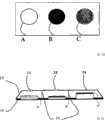
图5B为根据本发明第一优选实施例的实现为具有不同发射特性的同心环贴片的顶部视图;Figure 5B is a top view of concentric ring patches implemented with different emission characteristics according to the first preferred embodiment of the present invention;
图5C为根据本发明第一优选实施例的实现为具有不同发射特性的同心环贴片的截面侧视图;5C is a cross-sectional side view of concentric ring patches implemented with different emission characteristics according to the first preferred embodiment of the present invention;
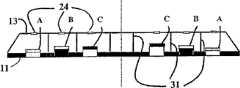
图5D为根据本发明第一优选实施例的实现为具有不同发射性、导电性及厚度的相邻环的贴片的顶部视图;5D is a top view of a patch implemented as adjacent rings with different emissivity, conductivity and thickness, according to the first preferred embodiment of the present invention;
图5E为根据本发明第一优选实施例的实现为具有不同发射性、导电性及厚度的相邻环的贴片的截面侧视图;5E is a cross-sectional side view of a patch implemented as adjacent rings of different emissivity, conductivity, and thickness in accordance with the first preferred embodiment of the present invention;
图6为热通量平衡图解;Fig. 6 is a heat flux balance diagram;
图7为根据本发明第二优选实施例的接触元件的截面侧视图;7 is a cross-sectional side view of a contact element according to a second preferred embodiment of the present invention;
图8A为根据本发明第二优选实施例的接触元件的顶部视图;Figure 8A is a top view of a contact element according to a second preferred embodiment of the present invention;
图8B为本发明第二优选实施例的截面侧视图;Figure 8B is a cross-sectional side view of a second preferred embodiment of the present invention;
图为根据本发明第三优选实施例的接触元件的截面侧视图。The figure is a cross-sectional side view of a contact element according to a third preferred embodiment of the present invention.
具体实施方式Detailed ways
本发明用于测量具有相当稳定的内部温度的内部区域的身体内部温度或热阻系数,与热导媒介相接触的区域包括一个或多个层,所述媒介有可用于读取涉及表面的温度的外表面。The present invention is used to measure the internal body temperature or thermal resistivity of an internal region having a fairly stable internal temperature, the region in contact with a thermally conductive medium comprising one or more layers that can be used to read the temperature of the involved surface the outer surface.
一个实例是测量流过绝缘管的液体的温度,该流动以管壁作为媒介及外表面为槽的外绝缘体。另一个实施例(图1)是测量病人血管温度(Tdeep),媒介为血管上的多层组织,外表面为皮肤表面(温度Ts)。An example is the measurement of the temperature of a liquid flowing through an insulating pipe, the flow being mediated by the pipe wall and an outer insulator whose outer surface is a groove. Another embodiment (FIG. 1) is to measure the temperature (Tdeep) of a patient's blood vessel, the medium being the multiple layers of tissue on the blood vessel, and the outer surface being the skin surface (Temperature Ts).
为了示意说明,本具体实施方式着重描述病人身体中心温度的测量。因此,必须记住本说明提到的“身体中心”,“组织”,及“皮肤表面”,这些术语分别代表了术语“具有十分稳定热状态的温度的内部区域”,“媒介”和“外表面”。For illustrative purposes, this specific embodiment focuses on the measurement of the core temperature of the patient's body. Therefore, it must be kept in mind that this description refers to "body center", "tissue", and "skin surface", which represent the terms "inner region having a temperature of a very stable thermal state", "medium" and "outer surface" respectively. surface".
图1表示了身体外表面的热通量q″s。热量在身体中心(Tdeep)流动,也通过一层或多层组织在外部皮肤表面(Ts)流动。方向为从高温区域向低温区域流动。如果温度恰好相同,则热通量等于0。假定身体热量处于相当稳定状态并且热通量基本上固定。Figure 1 shows the heat flux q″s on the outer surface of the body. Heat flows in the center of the body (Tdeep) and also flows through one or more layers of tissue on the outer skin surface (Ts). The direction is from the high temperature area to the low temperature area .If the temperatures happen to be the same, the heat flux is equal to 0. Body heat is assumed to be in a fairly steady state and the heat flux is essentially fixed.
本发明从涉及皮肤表面的温度测量中得到Ts和q″s ,接着确定Tdeep和/或传导媒介的热阻系数,通过以下一维稳态关系,定义为有效传导率及介质厚度的关系:The present invention obtains Ts and q″s from the temperature measurement involving the skin surface, then determines Tdeep and/or the thermal resistivity of the conduction medium, through the following one-dimensional steady-state relationship, defined as the relationship between effective conductivity and medium thickness:
其中:in:
q″s是由在皮肤表面若干位置测量的温度确定的热通量q″s is the heat flux determined by the temperature measured at several locations on the skin surface
Keff是皮肤表面和表面组织下的血管层之间所有层的总的等价传导率Keff is the total equivalent conductance of all layers between the skin surface and the vascular layer below the surface tissue
ΔX是从表面到血管层的距离ΔX is the distance from the surface to the vascular layer
TS是在皮肤表面测量的温度TS is the temperature measured at the skin surface
如前面已提到的,
本发明通过测量相当稳定的热状态下皮肤表面一个或多个点的温度得到Tdeep和/或所述传导媒介有效热阻性的值。所讨论的点位于无源设备或贴片上,与物体外表面接触足够长时间以达到热平衡状态。The present invention obtains the value of Tdeep and/or the effective thermal resistance of the conducting medium by measuring the temperature of one or more points on the skin surface in a relatively stable thermal state. The point in question is on a passive device or patch that is in contact with the outer surface of the object long enough to reach a state of thermal equilibrium.
图2表示出了本发明的主要元件。所述发明包括温度相关值的读取装置12,其可以以多种方式实现。图3A表示出了读取辐射红外能量的实际应用,图3B表示出了读取电信号的一个实现方式。Figure 2 shows the main elements of the invention. Said invention comprises a
贴片10是连接到病人身体的无源元件。它可以通过已公知的多种连接装置连接。例如,为了与身体相连,贴片10在与身体接触的表面可以包含胶沾或者用带子与身体连接。在工业应用中,贴片10可以通过扣件、焊接或其他现有技术中熟知的连接方式与物体连接。The
贴片10包括一个或多个处于热量十分稳定状态(热平衡)并且被一个或多个罩子13罩住的接触元件11。接触元件11具有高传导率的特性。接触元件11必须足够大以避免二维横向热通量效应,其从内部区域到外表面垂直于热量的轴向。接触元件的合适原料的示例是由不锈钢或涂有不会相互排斥的薄涂层的铝所制成的金属薄片。罩子13具有好的绝缘特性并且不传递辐射热量。它使接触元件11和周围热环境绝缘。由于这里利用了术语″贴片″,可以理解为一般指的是包括接触元件11和罩子13并系于所测量物体(如,病人的身体)的任何无源元件。The
由接触元件11和罩子13形成的体积23具有作为一个好的绝缘体的特性,例如,其为空气之类的气体,或者真空。其组成材料还取决于读取装置12所使用的类型。如果读取装置12是红外辐射辐射计,该体积还具有对红外辐射部分或完全透明的特性。如果读取装置基于其他原理,例如读取电子信号或与温度相关的电特性(如稍后所描述),该体积可以是对红外不透明的。The
读取装置12用于在接触元件11的点(在一个实施例中,也在罩子13)读取与温度相关的热量值。这可以用多种方式来完成。The
读取装置12的一种实现方式是作为红外辐射计在各点(图3A)读取红外辐射。在这个情况下,对于辐射不传热的罩子13有必要包含一个校准器19以把读取装置12定位于点上,以及在罩子13中定位一个小的接入点24,辐射计可以通过它读取辐射。实现接入点24的一种方式是使它永久红外透明但是又足够小以不明显溢出红外辐射,例如做成窗或者开口。另一种实施接入点24的方式是使它IR不透明但是可以在读取时由辐射计读取装置12打开,例如,作为被辐射计打开并且在移开辐射计时关闭的弹簧铰链快门,或者作为如用来让光进入摄像头的孔径之类的控光装置。虽然有多少辐射从接入点24中溢出在这个实施例和第二个实施例中并不紧要,尽量把这个值减小以得到更好的信噪比。One implementation of the
实现读取装置12的另一个方式是作为一个从电信号或电特性(图3B)中得出测量值的设备。在那个情况下,给所要读的贴片10上的点提供了一个温度传感器,如电热调节器25或热电偶,并且传感器输出经过导线28连到罩子13外部的终端27并且读取装置可以通过校准器19调整到它从而读取终端输出。为了提供热通量,我们可以使用由绝缘体26隔开的两个电热调节器。Another way of implementing the
处理单元14包括保持数据的存储器17及处理来自读取装置12的信号以确定所读取的各点温度及对这些温度运用算法来得出Tdeep的处理器15。The processing unit 14 includes a memory 17 for holding data and a processor 15 for processing the signal from the
用户接口16可包括各种用户控制接口,如显示频,峰鸣器,或控制键,来使用户可以操作读取装置12及获知处理信息,特别是Tdeep的值。The user interface 16 may include various user control interfaces, such as a display frequency, beeper, or control keys, so that the user can operate the
还可以给读取装置12或者处理单元14提供数据通信接口35来与外界设备,如个人计算机交流数据传输或控制。该交流可以是有线的或无线的,如一个标准通用串行总线(USB)接口。A data communication interface 35 may also be provided to the
电源33给读取装置12的有源元件,处理单元14,用户接口16供电。取决于应用,供应电源可以连接到稳恒电压源,可充电电池或电池组,或其他电源。The power supply 33 powers the active components of the
在本发明的多种实施方式,如这里所描述的医学应用中,最好基于使用或制造方便而把读取装置12,处理单元14,和用户接口16组合成单独设备。In various embodiments of the invention, such as the medical applications described herein, it may be desirable to combine
在例如医学应用的需要无菌的实施例中,读取装置12包括把读取装置12同贴片10的直接接触隔离以防交叉感染的装置。在这种情况下,读取装置12还包括在读取时与贴片接触的读取端,以及测量前连在读取端的一次性探头罩子。同样,在这些实施例中,贴片10最好实现为包括可生物兼容的便宜材料的一次性粘合贴片。In embodiments requiring sterility, such as in medical applications, the
贴片10可以包括标识信息装置如条形码及可以包括身份读取装备的读取装置12,如条形码读取装置。The
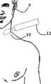
图4表示出了和病人9连接并被读取装置12读取的贴片10。在测量人体温度的这个情况下,贴片10最好连接到病人靠近动脉部位的皮肤,比如颈动脉,此处温度和身体中心温度十分相近。正如图形所示,本发明是非侵入式的,对病人和操作者都十分方便。贴片10可以和病人身体长时间保持接触,例如作为沾性贴片。在其与身体连接的短时间内,接触元件11达到稳定状态,之后其在任何时间都可以被读取装置读取。读取结果被处理单元16处理并得到内部温度(Tdeep)和/或热阻性,其可通过用户接口16传输到用户,例如作为一组七段显示的数字表示。内部温度及病人身份还可以通过通信接口如个人计算机的外部设备传达。FIG. 4 shows a
本发明主要存在三种最佳实施方式。这些实施方式一旦理解后,可以为本领域技术人员提供各种等价实现方式的启示。There are mainly three best implementation modes of the present invention. Once these implementations are understood, those skilled in the art may provide inspirations for various equivalent implementations.
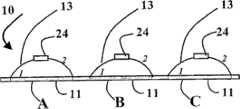
现在参考图3A描述本发明的第一实施例。该实施例要求读取装置12作为早前参考图3A所描述的红外辐射计实施方式。因此,在此实施例中,贴片10的罩子13包括接入点24,使得红外辐射可以被读取。这里实现了两个读取,一个通过接入点24在一个点测量红外辐射,如在图中标示在接触元件11的表面的1,另一个在罩子13的外表面,如图中表示的2。正如以后会解释的,为了最大的准确性,最好测量至少三对这种点1和2,例如如图5A所示使用贴片10实现。在那个实现方式中,接触元件11分为三个区间,A,B,和C,各自有不同的热边界条件,因此有不同的q″s和Ts。接触元件11上的热边界条件可以根据接触元件的本身特性,如厚度,传导率,以及发射率而改变。需要注意,有必要在各点间形成一定区别。可以通过利用上述特性中的一个或多个来达到这个目的。A first embodiment of the present invention will now be described with reference to FIG. 3A. This embodiment requires the
每个分区与其他分区热绝缘以消除各分区之间的侧向热传导或各部分之间的对流。所述热绝缘采用如图5A的完全隔离罩子13方式或在具有共同罩子的分区间的间隔物。Each partition is thermally insulated from the other partitions to eliminate lateral heat conduction between partitions or convection between sections. The thermal insulation is in the form of a completely
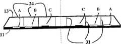
现在描述第一实施例的几种其他实现方式。图5B和图5C分别是接触元件11的实现方式的顶部视图和截面侧视图,其中区间A,B和C实现为具有不同发射特性并且与分隔装置31热绝缘的同心环。Several other implementations of the first embodiment are now described. 5B and 5C are respectively a top view and a cross-sectional side view of an implementation of the
图5D和图5E分别是接触元件11的实现方式的顶部视图和截面侧视图,其中截面A,B和C实现为具有不同发射特性并且与分隔装置31热绝缘的相邻环。5D and 5E are top and cross-sectional side views, respectively, of an implementation of the
图5F和图5G分别是接触元件11的实现方式的顶部视图和截面侧视图,其中截面A,B和C实现为与5D和5E相近似而其中截面A,B,C实现为同心环。Figures 5F and 5G are top and cross-sectional side views, respectively, of an implementation of the
现在参考图6描述热通量的测量。注意:接触元件11和皮肤之间的热流方向为从高温到低温。为了方便描述,假定接触元件11温度更低并且流向为从皮肤到元件。这同时表现在图6中。The measurement of heat flux will now be described with reference to FIG. 6 . Note: The direction of heat flow between the
我们可以忽略从接触元件11到环境的对流,因为它被绝缘罩子最小化。由于接触元件11处于热稳定状态,其表面为热平衡,使得进入元件的热量总量等于流出的热量。We can ignore the convection from the
因此,要么:Therefore, either:
(q″k·F1)+(q″in·F1)-(q″out·F1)=0:(当接触元件11处于热稳定状态(热平衡)(q″k ·F1 )+(q″in ·F1 )-(q″out ·F1 )=0: (when the
或:or:
(1)(q″out·F1)-(q″in·F1)=q″k·F1(1)(q″out F1 )-(q″in F1 )=q″k F1
其中in
F1是接触元件的表面面积F1 is the surface area of the contact element
并且,其中:and, where:
q″k·F1是单位时间通过传导从皮肤表面进入倒接触元件11的热能。q″k ·F1 is the heat energy entering the
qin″·F1是单位时间从罩子13辐射回接触元件11的输入热能。qin "·F1 is the input heat energy radiated from the
qout″·F1是单位时间从接触元件11辐射出去的热能。qout ″·F1 is the heat energy radiated from the
方程(1)除以F1并且定义输入和输出辐射的差值为Δq,我们得到:Dividing equation (1 ) by F and defining the difference between input and output radiation as Δq, we get:
(2)Δq=qout″-qin″=qk″(2) Δq=qout ″-qin ″=qk ″
对于稳定状态并且省略对流损失,通过热通量的定义我们得到:For steady state and omitting convective losses, by definition of heat flux we get:
然而,对于两面共辐射的情况,从辐射方程可以轻易得到Δq,在这我们可以通过下式得到:However, for the case of co-radiation on both sides, Δq can be easily obtained from the radiation equation, where we can obtain it by the following formula:
或者,通过替代方程(2)Alternatively, by substituting equation (2)
其中σ是stephan bolzman常数。where σ is the stephan bolzman constant.
T2是绝缘罩子13的温度,其可以直接测量得到。T1是点1处接触元件11表面的温度,其由辐射计读取装置12间接测量得到。利用方程(4)中的T1和T2,可以计算接触元件表面点1的输入传导热流(q″k)。应当注意由于q″k及q″s都代表接触元件表面的热通量,所以它们相等。因此,可以用q″s替换方程(3)中的q″k。T2 is the temperature of the insulating
在方程(3)中,我们有
Tsurface为T1,Tsurface及q″k都由计算得到。存在多种方式来求得剩余的两个未知量

一种方式是最小二乘法(Least Square)。对于2个未知数,至少需要3个方程。这3个方程的值可以通过在A、B、C三个不同点测量来得到,每个点具有独特的热边界条件,其在该点形成了独特的表面温度。所述热边界温度指的是不同的导电性、厚度、发射性或其结合。对每点重复方程(3)生成了一系列线性方程。One way is the least square method (Least Square). For 2 unknowns, at least 3 equations are required. The values of these 3 equations can be obtained by measuring at three different points A, B, C, each point has a unique thermal boundary condition, which creates a unique surface temperature at that point. The thermal boundary temperature refers to different conductivity, thickness, emissivity or combinations thereof. Repeating equation (3) for each point generates a series of linear equations.
我们定义未知矢量:We define the unknown vector:
及矩阵and matrix
其中
在三个点的表面温度测量值的矢量。A vector of surface temperature measurements at three points.
我们可以以下列方式重写(3):We can rewrite (3) in the following way:
维数(3*2) (2*1) (3*1)Dimension(3*2) (2*1) (3*1)
其中A为“模型”矩阵,

正如所提到的,为了得到三个表面测量点,在贴片10的接触元件11上提供了三个区域(A,B,C),每个区域具有不同的热边界条件并且彼此间几乎热绝缘。图5A示出了贴片10实施例的一个实现例子。其中贴片被分为具有不同放射性的区域A、B和C,每个区域具有自己的罩子13。作为替换,也可以使用一个单独的罩子,中间用间隔物隔开每个分区。除了表面测量之外,在至少一个罩子13上作了T2的测量。As mentioned, in order to obtain three surface measurement points, three regions (A, B, C) are provided on the
如果每个分区的发射性区别足够大,我们会测量三个不同的表面温度


辐射计被用来在区域A,B和C的点T读取接触元件11的有效表面温度Te,并且它被用来读取点2处罩子13的温度T2。The radiometer is used to read the effective surface temperatureTe of the
现在描述辐射计12的校准。在对黑体的校准中,对于每一度温度,在辐射计的感应器上测量的输出能量为:Calibration of the
其中:dO=感应器的半径where: dO = radius of the sensor
ω=感应器的空间角度ω = spatial angle of the sensor
τo=红外读取接入点24的传输性τo = transmission of infrared
σ=Stephan Bolzman常数σ = Stephan Bolzman constant
Te=黑体的有效温度Te = effective temperature of the blackbody
在我们的情况下,辐射倒辐射计所产生的能量测量:In our case, the energy measurement produced by the radiobolometer:
(6)
即,在辐射计里测量的温度是T1和T2的结合。That is, the temperature measured in the radiometer is the combination ofT1 andT2 .
我们可以简化并写为:We can simplify and write as:
Te4=ε1JT14+ρε2JT24Te4 =ε1J T14 +ρε2J T24
如果我们把ε2J和ε1J替换掉,可以得到If we replace ε2J and ε1J , we get
本方程把读取装置12在接触元件11上的点1探测到的温度Te与读取装置在绝缘外罩表面点2探测到的温度T2联系了起来。This equation relates the temperatureTe detected by the
因此,一旦我们定义了值ε1,ε2,F1,F2,ρ2和T2,我们可以很容易通过位置1辐射计读取的Te得到值T1。Therefore, once we define the values ε1 , ε2 , F1 , F2 , ρ2 and T2 , we can easily get the value T1 from the Te read by the
现在参考图7描述本发明的第二实施例,该图在本实施例中是贴片10的截面视图。A second embodiment of the invention will now be described with reference to FIG. 7 , which in this embodiment is a cross-sectional view of a
然而,在第一实施例中T1(表面温度)和q″k通过方程(4)得到,在这里描述的第二实施例中,参数q″k通过直接测量接触元件表面两点之间的温差来测量。Whereas in the first embodimentT1 (surface temperature) and q″k are obtained by equation (4), in the second embodiment described here the parameter q″k is obtained by directly measuring the contact element surface between two points temperature difference to measure.
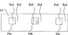
在本实施例中,接触元件11包括具有由不同的热导性、不同的厚度确定的不同的热边界条件的测量点,例如,在图7中,点S直接位于接触元件11上而点C在绝缘层19上。In this embodiment, the
正如前面描述的,每个点(S和C)由罩子13罩住。点S和C上的温度被读取装置12读取,该读取装置可以是前面所述实施方式的任何一种(如辐射计,传感信号读取装置,或其他点热量值读取装置)。Each point (S and C) is covered by a
在区域S,辐射计直接测量接触表面的稳态温度,该温度定义为TS。在区域C,辐射计测量绝缘元件19上的温度TC,该温度低于TS。In region S, the radiometer directly measures the steady-state temperature of the contact surface, which is defined as TS . In zone C, the radiometer measures the temperature TC on the insulating
绝缘19(点C)顶上的热通量可由下式得到:The heat flux on top of insulation 19 (point C) is given by:
假定不存在由于空间热量流动引起的侧向效应。It is assumed that there are no side effects due to space heat flow.
因此,由接触元件11上点(S和C)之间温差可以得到一个与热通量线性相关的数值。为了防止侧向效应,接触元件相应于点S和点C之间的距离必须相对较大。Thus, from the temperature difference between the points (S and C) on the contact element 11 a value linearly related to the heat flux can be obtained. In order to prevent lateral effects, the distance between the contact elements corresponding to points S and C must be relatively large.
由于在稳态下所有流过各层的热通量为常数,可以写出:Since all heat fluxes through the layers are constant at steady state, it can be written:

从这我们得到:From this we get:
为了解出该方程,我们会注意到此处的未知量为:To solve the equation, we note that the unknowns here are:

必须注意到


注意:在接触元件11具有高传导率的情况下,Ts1~Ts2~Ts3所以足够测量一个Ts值。Note: In the case that the
这种接触元件11的结构显示在图8A的顶部视图及图8B的侧面视图中。The structure of such a
在贴片中使用热或温度传感器的情况下,位于一个位置的每对传感器应该以一个置于另一个之上的方式放置,中间有一个绝缘元件26,如图3B所示的一个位置。每个测量位置都有这种配置。在具有三个测量位置的情况下,会有三对热或温度传感器及三个绝缘元件。Where heat or temperature sensors are used in the patch, each pair of sensors at one location should be placed one above the other with an insulating
应该注意ΔXs和Ks在一些或所有测量位置都相同,只要保持下列关系:It should be noted that ΔXs and Ks are the same at some or all measurement locations, provided the following relationship holds:
i,j=1...3 j≠ii, j=1...3 j≠i
由于有三个测量点,我们可以分别得到Tsi和Tci的三个测量值,其可以定义为三个不同的ΔTi。我们可以写成向量形式:Since there are three measurement points, we can obtain three measured values of Tsi and Tci respectively, which can be defined as three different ΔTi. We can write it in vector form:

维数:3×2 2×1 3×1Dimensions: 3×2 2×1 3×1
可以写成:
这个原理可以应用到三个或更多位置。This principle can be applied to three or more locations.
参考图9,现在描述本发明的第三个实施例,该图为贴片10的截面侧视图。在这个配置下我们假设qs″≈0以及在表面上没有发生辐射或对流。在这个情况下,如果接触元件11大到可以避免侧向热通量以及罩子内部及外表面的发射率都很低(假如有一个反射表面)以及接入元件24不会泄漏大量的辐射(例如面积小于罩子总面积5%的小开口),接着我们假设Ts与Tdeep接近到足以视为相等。因此,可以利用Ts的直接测量来得到Tdeep。例如,在人体温度测量的情况下,贴片的直径大于20mm并且罩子在其两面上的发射率小于0.1。A third embodiment of the invention will now be described with reference to Figure 9, which is a cross-sectional side view of a
为了得到好的信噪比,可以使用高发射率的表面37来读取,例如发射率为0.8-0.9。为了确定媒介和贴片是否处于热平衡状态,有必要对Ts进行多次测量。一旦这些值的波动小于预定可接收的范围,比如说小于1%,即达到热平衡状态的条件并且可以得到Tdeep的值。In order to obtain a good signal-to-noise ratio, a high-emissivity surface 37 can be used for reading, for example an emissivity of 0.8-0.9. Multiple measurements of Ts are necessary to determine whether the medium and patch are in thermal equilibrium. Once the fluctuation of these values is less than the predetermined acceptable range, say less than 1%, the condition of thermal equilibrium state is reached and the value of Tdeep can be obtained.
总之,本发明提供了一种快速非侵入式的确定物体内部温度的装置。通过参考身体温度的实现例子解释了本发明,本发明可以用于其他动物体,同时也可以用于非动物体。In summary, the present invention provides a means for quickly and non-intrusively determining the internal temperature of an object. The invention is explained with reference to the implementation example of body temperature, and the invention can be applied to other animal bodies as well as to non-animal bodies.
必须清楚,所述实施例的描述和本说明书提供的附图只用于更好地理解本发明,并不限制如接下来权利要求所覆盖的范围。It must be clear that the description of the described embodiments and the drawings provided in this specification are only for better understanding of the invention and do not limit the scope as covered by the following claims.
同样必须清楚,本领域的技术人员在读完本说明书后,对附图及以上所描述的实施例所做的调整和修改,依然属于以下权利要求所包括的范围。It must also be clear that adjustments and modifications made to the drawings and the above-described embodiments by those skilled in the art after reading this specification still fall within the scope of the following claims.
Claims (36)
Translated fromChinese
Applications Claiming Priority (2)
| Application Number | Priority Date | Filing Date | Title |
|---|---|---|---|
| US57265104P | 2004-05-20 | 2004-05-20 | |
| US60/572,651 | 2004-05-20 |
Publications (1)
| Publication Number | Publication Date |
|---|---|
| CN101247756Atrue CN101247756A (en) | 2008-08-20 |
Family
ID=35428715
Family Applications (1)
| Application Number | Title | Priority Date | Filing Date |
|---|---|---|---|
| CNA2005800160141APendingCN101247756A (en) | 2004-05-20 | 2005-05-18 | temperature measuring device |
Country Status (5)
| Country | Link |
|---|---|
| US (1) | US7479116B2 (en) |
| EP (1) | EP1804653A4 (en) |
| JP (1) | JP4751386B2 (en) |
| CN (1) | CN101247756A (en) |
| WO (1) | WO2005112547A2 (en) |
Cited By (18)
| Publication number | Priority date | Publication date | Assignee | Title |
|---|---|---|---|---|
| CN102483345A (en)* | 2009-07-23 | 2012-05-30 | 梅特勒-托利多公开股份有限公司 | Method For Correcting The Temperature Of A Force Measuring Apparatus And Force Measuring Apparatus |
| CN103162837A (en)* | 2013-02-05 | 2013-06-19 | 东华大学 | On-line measurement method of fiber temperature |
| CN103169455A (en)* | 2013-04-08 | 2013-06-26 | 杭州莱克思大医疗用品有限公司 | Medical temperature monitoring probe with identity recognition function |
| CN103596490A (en)* | 2011-06-15 | 2014-02-19 | 皇家飞利浦有限公司 | Peripheral temperature measuring |
| CN104161497A (en)* | 2013-05-17 | 2014-11-26 | 黄首征 | Isolated skin temperature collection device |
| CN104458037A (en)* | 2013-09-18 | 2015-03-25 | 上海电缆研究所 | Cable conductor temperature measuring device and method |
| CN104434048A (en)* | 2014-12-01 | 2015-03-25 | 电子科技大学 | Instrument and method for measuring temperature of deep tissue of human body |
| CN104596669A (en)* | 2013-10-30 | 2015-05-06 | 上海电缆研究所 | Distributive temperature measuring device for cable conductor |
| CN104665777A (en)* | 2015-01-30 | 2015-06-03 | 深圳市泰金田科技有限公司 | Human body temperature real-time monitoring system |
| CN104688196A (en)* | 2013-12-05 | 2015-06-10 | 舜新生物科技股份有限公司 | Surface mount type temperature measuring device |
| CN105051509A (en)* | 2013-04-05 | 2015-11-11 | 德尔格医疗有限责任公司 | Body core temperature sensor |
| CN105939654A (en)* | 2013-12-31 | 2016-09-14 | i4c创新公司 | Paired thermometer temperature determination |
| CN106377230A (en)* | 2016-03-22 | 2017-02-08 | 深圳九星印刷包装集团有限公司 | Temperature measuring system and temperature measuring device thereof |
| CN109154527A (en)* | 2016-05-27 | 2019-01-04 | 琼德泰克森谢尔有限公司 | Calibrate the heat flux sensor for measuring individual body temperature |
| CN109855755A (en)* | 2017-11-30 | 2019-06-07 | 科技共享股份有限公司 | Biological data measurement apparatus |
| CN111513824A (en)* | 2020-05-01 | 2020-08-11 | 哈尔滨医科大学 | Disposable arterial blood gas puncture patch |
| CN111565625A (en)* | 2017-12-26 | 2020-08-21 | 罗伯特·博世有限公司 | System and method for detecting thickness of layer |
| WO2020238946A1 (en)* | 2019-05-28 | 2020-12-03 | 成都凡米科技有限公司 | Temperature measurement patch, temperature measurement system, and wearable article |
Families Citing this family (20)
| Publication number | Priority date | Publication date | Assignee | Title |
|---|---|---|---|---|
| US7857507B2 (en)* | 2004-11-16 | 2010-12-28 | Welch Allyn, Inc. | Temperature patch and method of using the same |
| JP4434214B2 (en)* | 2007-02-08 | 2010-03-17 | 株式会社デンソー | Battery state detection device |
| WO2008105869A1 (en) | 2007-02-26 | 2008-09-04 | Welch Allyn, Inc. | Multi-site infrared thermometer |
| US20080239920A1 (en)* | 2007-03-27 | 2008-10-02 | Francesco Pompei | Wireless transmission of temperature data |
| US20120083710A1 (en) | 2010-09-30 | 2012-04-05 | Medism Ltd. | Ergonomic hand-held thermometer |
| US8657758B2 (en)* | 2010-12-02 | 2014-02-25 | Welch Allyn, Inc. | Devices and methods for temperature determination |
| CN102135512B (en)* | 2011-03-04 | 2013-06-05 | 北京大学 | Method for testing variation of thermal boundary resistance relative to size of square nanowires |
| US10244986B2 (en) | 2013-01-23 | 2019-04-02 | Avery Dennison Corporation | Wireless sensor patches and methods of manufacturing |
| US9599521B2 (en) | 2014-01-27 | 2017-03-21 | Medisim, Ltd. | Interface between vital-signs sensors and patient monitor |
| US9375149B2 (en)* | 2014-03-18 | 2016-06-28 | Welch Allyn, Inc. | Noncontact thermometry systems and methods |
| CN208818370U (en)* | 2015-09-04 | 2019-05-03 | Lg伊诺特有限公司 | temperature sensing device |
| KR20170028782A (en)* | 2015-09-04 | 2017-03-14 | 엘지이노텍 주식회사 | Patch type thermometer by measuring infrared rays |
| US11224344B2 (en)* | 2016-08-19 | 2022-01-18 | James Foody | Method and system for determination of core body temperature |
| US11089961B2 (en) | 2016-08-19 | 2021-08-17 | James Foody | System and method for monitoring core body temperature |
| US10856741B2 (en)* | 2016-12-14 | 2020-12-08 | Vital Connect, Inc. | Core body temperature detection device |
| DE102017010801A1 (en) | 2017-11-22 | 2019-05-23 | Drägerwerk AG & Co. KGaA | A method for non-contact skin temperature determination and apparatus for carrying out the method |
| JP7073940B2 (en)* | 2018-06-27 | 2022-05-24 | 日本電信電話株式会社 | In-vivo temperature measuring device and in-vivo temperature measuring method |
| US11635334B2 (en)* | 2020-06-30 | 2023-04-25 | Apple Inc. | Miniature external temperature sensing device for estimating subsurface tissue temperatures |
| US11408778B2 (en) | 2020-07-21 | 2022-08-09 | Apple Inc. | Temperature gradient sensing in portable electronic devices |
| US11771329B2 (en) | 2020-09-24 | 2023-10-03 | Apple Inc. | Flexible temperature sensing devices for body temperature sensing |
Family Cites Families (18)
| Publication number | Priority date | Publication date | Assignee | Title |
|---|---|---|---|---|
| GB2131175B (en)* | 1982-09-15 | 1986-05-21 | South Western Ind Res | Measuring temperatures and heat transfer coefficients |
| JPS61296227A (en)* | 1985-06-24 | 1986-12-27 | Matsushita Electric Works Ltd | Electronic clinical thermometer |
| JPS6358223A (en)* | 1986-08-29 | 1988-03-14 | Tatsuo Togawa | Clinical thermometer device |
| US5050612A (en)* | 1989-09-12 | 1991-09-24 | Matsumura Kenneth N | Device for computer-assisted monitoring of the body |
| US5249864A (en)* | 1992-10-23 | 1993-10-05 | Gas Research Institute | System for characterizing temperature of fluids |
| US5645349A (en)* | 1994-01-10 | 1997-07-08 | Thermoscan Inc. | Noncontact active temperature sensor |
| FI96066C (en)* | 1994-03-24 | 1996-04-25 | Polar Electro Oy | Method and apparatus for determining the internal temperature and coefficient of heat conduction in a structure |
| JP2666781B2 (en)* | 1995-07-31 | 1997-10-22 | 日本電気株式会社 | Body temperature pickup with adhesive pad |
| IL120758A (en) | 1997-05-01 | 2000-02-29 | Medisim Ltd | High speed accurate temperature measuring device |
| JPH11132857A (en)* | 1997-10-28 | 1999-05-21 | Matsushita Electric Works Ltd | Infrared detector |
| WO1999058050A1 (en)* | 1998-05-13 | 1999-11-18 | Cygnus, Inc. | Signal processing for measurement of physiological analytes |
| US6292685B1 (en)* | 1998-09-11 | 2001-09-18 | Exergen Corporation | Temporal artery temperature detector |
| US6220750B1 (en) | 1999-03-29 | 2001-04-24 | Yoram Palti | Non-invasive temperature measurement method and apparatus |
| EP1249691A1 (en)* | 2001-04-11 | 2002-10-16 | Omron Corporation | Electronic clinical thermometer |
| US7204425B2 (en) | 2002-03-18 | 2007-04-17 | Precision Dynamics Corporation | Enhanced identification appliance |
| JP4157914B2 (en)* | 2002-03-20 | 2008-10-01 | 坂野 數仁 | Temperature measuring apparatus and temperature measuring method |
| TW555965B (en)* | 2002-10-07 | 2003-10-01 | Opto Tech Corp | Temperature measurement device |
| US20050101843A1 (en)* | 2003-11-06 | 2005-05-12 | Welch Allyn, Inc. | Wireless disposable physiological sensor |
- 2005
- 2005-05-18USUS11/597,246patent/US7479116B2/ennot_activeExpired - Fee Related
- 2005-05-18WOPCT/IL2005/000513patent/WO2005112547A2/enactiveApplication Filing
- 2005-05-18CNCNA2005800160141Apatent/CN101247756A/enactivePending
- 2005-05-18EPEP05740493Apatent/EP1804653A4/ennot_activeWithdrawn
- 2005-05-18JPJP2007517646Apatent/JP4751386B2/ennot_activeExpired - Fee Related
Cited By (28)
| Publication number | Priority date | Publication date | Assignee | Title |
|---|---|---|---|---|
| CN102483345B (en)* | 2009-07-23 | 2015-02-18 | 梅特勒-托利多公开股份有限公司 | Method For Correcting The Temperature Of A Force Measuring Apparatus And Force Measuring Apparatus |
| CN102483345A (en)* | 2009-07-23 | 2012-05-30 | 梅特勒-托利多公开股份有限公司 | Method For Correcting The Temperature Of A Force Measuring Apparatus And Force Measuring Apparatus |
| US9074925B2 (en) | 2009-07-23 | 2015-07-07 | Mettler-Toledo Ag | Method for the temperature-correction of a force-measuring device, and force-measuring device |
| CN103596490A (en)* | 2011-06-15 | 2014-02-19 | 皇家飞利浦有限公司 | Peripheral temperature measuring |
| CN103162837B (en)* | 2013-02-05 | 2015-02-18 | 东华大学 | On-line measurement method of fiber temperature |
| CN103162837A (en)* | 2013-02-05 | 2013-06-19 | 东华大学 | On-line measurement method of fiber temperature |
| US11051700B2 (en) | 2013-04-05 | 2021-07-06 | Drägerwerk AG & Co. KGaA | Body core temperature sensor |
| CN105051509A (en)* | 2013-04-05 | 2015-11-11 | 德尔格医疗有限责任公司 | Body core temperature sensor |
| CN103169455A (en)* | 2013-04-08 | 2013-06-26 | 杭州莱克思大医疗用品有限公司 | Medical temperature monitoring probe with identity recognition function |
| CN104161497A (en)* | 2013-05-17 | 2014-11-26 | 黄首征 | Isolated skin temperature collection device |
| CN104458037A (en)* | 2013-09-18 | 2015-03-25 | 上海电缆研究所 | Cable conductor temperature measuring device and method |
| CN104458037B (en)* | 2013-09-18 | 2017-09-01 | 上海电缆研究所有限公司 | Cable conductor temperature measuring device and its measuring method |
| CN104596669A (en)* | 2013-10-30 | 2015-05-06 | 上海电缆研究所 | Distributive temperature measuring device for cable conductor |
| CN104688196A (en)* | 2013-12-05 | 2015-06-10 | 舜新生物科技股份有限公司 | Surface mount type temperature measuring device |
| CN105939654A (en)* | 2013-12-31 | 2016-09-14 | i4c创新公司 | Paired thermometer temperature determination |
| CN104434048B (en)* | 2014-12-01 | 2016-08-24 | 电子科技大学 | A kind of human body deep tissue temperature measuring instrument and measuring method |
| CN104434048A (en)* | 2014-12-01 | 2015-03-25 | 电子科技大学 | Instrument and method for measuring temperature of deep tissue of human body |
| CN104665777A (en)* | 2015-01-30 | 2015-06-03 | 深圳市泰金田科技有限公司 | Human body temperature real-time monitoring system |
| CN106377230A (en)* | 2016-03-22 | 2017-02-08 | 深圳九星印刷包装集团有限公司 | Temperature measuring system and temperature measuring device thereof |
| CN106377230B (en)* | 2016-03-22 | 2019-12-27 | 深圳九星印刷包装集团有限公司 | Temperature measuring system and temperature measuring device thereof |
| CN109154527A (en)* | 2016-05-27 | 2019-01-04 | 琼德泰克森谢尔有限公司 | Calibrate the heat flux sensor for measuring individual body temperature |
| CN109154527B (en)* | 2016-05-27 | 2020-06-09 | 琼德泰克森谢尔有限公司 | Calibrating heat flux sensors for measuring individual body temperature |
| CN109855755A (en)* | 2017-11-30 | 2019-06-07 | 科技共享股份有限公司 | Biological data measurement apparatus |
| CN111565625A (en)* | 2017-12-26 | 2020-08-21 | 罗伯特·博世有限公司 | System and method for detecting thickness of layer |
| CN111565625B (en)* | 2017-12-26 | 2024-03-26 | 罗伯特·博世有限公司 | System and method for detecting thickness of layer |
| WO2020238946A1 (en)* | 2019-05-28 | 2020-12-03 | 成都凡米科技有限公司 | Temperature measurement patch, temperature measurement system, and wearable article |
| CN111513824A (en)* | 2020-05-01 | 2020-08-11 | 哈尔滨医科大学 | Disposable arterial blood gas puncture patch |
| CN111513824B (en)* | 2020-05-01 | 2021-03-19 | 哈尔滨医科大学 | Disposable arterial blood gas puncture patch |
Also Published As
| Publication number | Publication date |
|---|---|
| EP1804653A2 (en) | 2007-07-11 |
| US20080071189A1 (en) | 2008-03-20 |
| WO2005112547A3 (en) | 2007-06-28 |
| US7479116B2 (en) | 2009-01-20 |
| EP1804653A4 (en) | 2009-08-19 |
| JP4751386B2 (en) | 2011-08-17 |
| JP2008503307A (en) | 2008-02-07 |
| WO2005112547A2 (en) | 2005-12-01 |
Similar Documents
| Publication | Publication Date | Title |
|---|---|---|
| CN101247756A (en) | temperature measuring device | |
| US7981046B2 (en) | Temperature measurement device | |
| KR102630649B1 (en) | Apparatus, systems and methods for non-invasive thermal irradiation | |
| EP1857795B1 (en) | Tympanic thermometer | |
| US7841767B2 (en) | Thermal tympanic thermometer | |
| RU2489690C2 (en) | Temperature sensor design | |
| EP1857797B1 (en) | Radiation thermometer calibration | |
| US6971790B2 (en) | Thermometry probe calibration method | |
| JP7151607B2 (en) | Temperature measuring device and temperature measuring method | |
| GB2133886A (en) | Fast response temperature sensing probe | |
| US11802799B2 (en) | Temperature measuring device and method for determining temperature | |
| US5967992A (en) | Radiometric temperature measurement based on empirical measurements and linear functions | |
| Carnochan et al. | The practical use of thermocouples for temperature measurement in clinical hyperthermia | |
| JP2603004B2 (en) | Temperature measuring device and method for providing temperature signal | |
| Okabe et al. | Development of a guard-heated thermistor probe for the accurate measurement of surface temperature | |
| Wang et al. | A digital thermometer with fast response and high precision | |
| Niedermann et al. | Heat flux measurements for use in physiological and clothing research | |
| Martín et al. | Best practice guide: Use of infrared forehead thermometers to perform traceable non-contact measurements of human body temperature | |
| JP2003156395A (en) | Infrared temperature sensor | |
| CN112113664A (en) | Infrared temperature sensor, probe comprising same and infrared thermometer | |
| Diller | Practical Heat Flux Measurement | |
| JPS61288133A (en) | Measuring instrument for radiation heating value | |
| Grodzinsky et al. | Technical Accuracy | |
| Kiruthiga et al. | The predominant role and the need of thermometers | |
| Yap Kannan et al. | Infrared cameras are potential traceable “fixed points” for future thermometry studies |
Legal Events
| Date | Code | Title | Description |
|---|---|---|---|
| C06 | Publication | ||
| PB01 | Publication | ||
| C10 | Entry into substantive examination | ||
| SE01 | Entry into force of request for substantive examination | ||
| C02 | Deemed withdrawal of patent application after publication (patent law 2001) | ||
| WD01 | Invention patent application deemed withdrawn after publication | Open date:20080820 |