CN101247423B - Mobile terminal device - Google Patents
Mobile terminal deviceDownload PDFInfo
- Publication number
- CN101247423B CN101247423BCN2008100056389ACN200810005638ACN101247423BCN 101247423 BCN101247423 BCN 101247423BCN 2008100056389 ACN2008100056389 ACN 2008100056389ACN 200810005638 ACN200810005638 ACN 200810005638ACN 101247423 BCN101247423 BCN 101247423B
- Authority
- CN
- China
- Prior art keywords
- upper case
- case
- state
- terminal device
- mobile terminal
- Prior art date
- Legal status (The legal status is an assumption and is not a legal conclusion. Google has not performed a legal analysis and makes no representation as to the accuracy of the status listed.)
- Expired - Fee Related
Links
Images


Classifications
- H—ELECTRICITY
- H04—ELECTRIC COMMUNICATION TECHNIQUE
- H04M—TELEPHONIC COMMUNICATION
- H04M1/00—Substation equipment, e.g. for use by subscribers
- H04M1/02—Constructional features of telephone sets
- H04M1/0202—Portable telephone sets, e.g. cordless phones, mobile phones or bar type handsets
- H04M1/0206—Portable telephones comprising a plurality of mechanically joined movable body parts, e.g. hinged housings
- H04M1/0208—Portable telephones comprising a plurality of mechanically joined movable body parts, e.g. hinged housings characterized by the relative motions of the body parts
- H04M1/0214—Foldable telephones, i.e. with body parts pivoting to an open position around an axis parallel to the plane they define in closed position
- A—HUMAN NECESSITIES
- A01—AGRICULTURE; FORESTRY; ANIMAL HUSBANDRY; HUNTING; TRAPPING; FISHING
- A01K—ANIMAL HUSBANDRY; AVICULTURE; APICULTURE; PISCICULTURE; FISHING; REARING OR BREEDING ANIMALS, NOT OTHERWISE PROVIDED FOR; NEW BREEDS OF ANIMALS
- A01K95/00—Sinkers for angling
- A—HUMAN NECESSITIES
- A01—AGRICULTURE; FORESTRY; ANIMAL HUSBANDRY; HUNTING; TRAPPING; FISHING
- A01K—ANIMAL HUSBANDRY; AVICULTURE; APICULTURE; PISCICULTURE; FISHING; REARING OR BREEDING ANIMALS, NOT OTHERWISE PROVIDED FOR; NEW BREEDS OF ANIMALS
- A01K97/00—Accessories for angling
- H—ELECTRICITY
- H04—ELECTRIC COMMUNICATION TECHNIQUE
- H04M—TELEPHONIC COMMUNICATION
- H04M1/00—Substation equipment, e.g. for use by subscribers
- H04M1/02—Constructional features of telephone sets
- H04M1/0202—Portable telephone sets, e.g. cordless phones, mobile phones or bar type handsets
- H04M1/0206—Portable telephones comprising a plurality of mechanically joined movable body parts, e.g. hinged housings
- H04M1/0208—Portable telephones comprising a plurality of mechanically joined movable body parts, e.g. hinged housings characterized by the relative motions of the body parts
- H04M1/0225—Rotatable telephones, i.e. the body parts pivoting to an open position around an axis perpendicular to the plane they define in closed position
- H04M1/0227—Rotatable in one plane, i.e. using a one degree of freedom hinge
- H—ELECTRICITY
- H04—ELECTRIC COMMUNICATION TECHNIQUE
- H04M—TELEPHONIC COMMUNICATION
- H04M1/00—Substation equipment, e.g. for use by subscribers
- H04M1/02—Constructional features of telephone sets
- H04M1/0202—Portable telephone sets, e.g. cordless phones, mobile phones or bar type handsets
- H04M1/0206—Portable telephones comprising a plurality of mechanically joined movable body parts, e.g. hinged housings
- H04M1/0208—Portable telephones comprising a plurality of mechanically joined movable body parts, e.g. hinged housings characterized by the relative motions of the body parts
- H04M1/0225—Rotatable telephones, i.e. the body parts pivoting to an open position around an axis perpendicular to the plane they define in closed position
- H04M1/0233—Including a rotatable display body part
Landscapes
- Engineering & Computer Science (AREA)
- Signal Processing (AREA)
- Life Sciences & Earth Sciences (AREA)
- Environmental Sciences (AREA)
- Animal Husbandry (AREA)
- Biodiversity & Conservation Biology (AREA)
- Telephone Set Structure (AREA)
Abstract
Description
Translated fromChinese技术领域technical field
本发明涉及一种可折叠式移动终端装置,该装置的上壳体和下壳体可转动地相连。The invention relates to a foldable mobile terminal device, the upper shell and the lower shell of which are rotatably connected.
背景技术Background technique
近年来,手机配备有:用于对物体拍照的照相功能、用于浏览网站的浏览器功能、用于收看电视节目等的电视功能,另外还具有标准的谈话功能、用于电子邮件的收发功能,等等。手机不仅用作执行通信的装置,而且还在各年龄段的人中用作其自身的、代替数码相机、个人电脑和电视的多功能终端。In recent years, mobile phones have been equipped with: a camera function for taking pictures of objects, a browser function for browsing websites, a TV function for watching TV programs, etc., and also has a standard conversation function, and a function for sending and receiving e-mails. ,etc. Cell phones are not only used as devices for performing communication, but also as multifunctional terminals of their own, replacing digital cameras, personal computers, and televisions, among people of all ages.
然而,尽管常见的电视或个人电脑具有呈水平伸长形状的显示屏,但是手机终端典型地具有整体上竖直伸长的形状,并且其显示屏也具有竖直伸长的形状以提高单手的握持性和可操作性。因此,当利用手机浏览电视或个人电脑上所显示的水平伸长形状的图像时,该图像通常通过减小其尺寸以与竖直伸长形状的显示屏保持一致而被显示,或该图像通常相对于显示屏显示于一边,用户通过握持手机的一边而浏览该图像。这样就产生了手机的图像尺寸与手机的握持性中的任一个要对另一个作出牺牲的问题。However, while a common TV or personal computer has a display screen in a horizontally elongated shape, a mobile phone terminal typically has a vertically elongated shape as a whole, and its display screen also has a vertically elongated shape to improve one-handed viewing. grip and maneuverability. Therefore, when viewing a horizontally elongated image displayed on a TV or a personal computer using a mobile phone, the image is usually displayed by reducing its size to conform to a vertically elongated display screen, or the image is usually Displayed on one side relative to the display screen, the user views the image by holding the side of the phone. Thus, there arises a problem that one of the image size of the mobile phone and the gripability of the mobile phone must be sacrificed to the other.
日本未经审查的专利申请第2003-319043号公报公开了一种可折叠式手机,该手机包括:具有显示屏的上壳体、具有控制器(operator)的下壳体以及支承壳体,该支承壳体铰接至下壳体并支承上壳体以便能够使上壳体围绕轴沿左/右方向转动。Japanese Unexamined Patent Application Publication No. 2003-319043 discloses a foldable mobile phone comprising: an upper case with a display screen, a lower case with a controller (operator), and a supporting case. The support case is hinged to the lower case and supports the upper case so as to be able to turn the upper case in a left/right direction about a shaft.
然而,如上述专利文献中的图2所示,当上壳体围绕设置到支承壳体上的轴转动时,为了防止上壳体的角部受到铰接件的干涉,上壳体的下边缘必须从其中心朝向上壳体100A的左右边缘显著地弯曲。因此,在该专利文献描述的可折叠式手机中,会产生显示屏的尺寸减小或该装置的设计受限的问题。However, as shown in FIG. 2 in the above-mentioned patent document, when the upper case is rotated around the shaft provided on the support case, in order to prevent the corners of the upper case from being interfered by the hinges, the lower edge of the upper case must be It is significantly curved from the center thereof toward the left and right edges of the
发明内容Contents of the invention
一种移动终端装置,其包括下壳体、上壳体和中间壳体。该中间壳体通过铰接结构连接至该下壳体,该铰接结构能够使该中间壳体围绕轴线转动。该中间壳体通过该中间壳体的前表面支撑该上壳体的后表面。第一壳体为上壳体或中间壳体,该第一壳体具有沿相对于转动轴线的竖直方向形成于面向第二壳体的表面的第一槽,该第二壳体为上壳体和中间壳体的另一个,该第二壳体具有第一部分,该第一部分从面向该第一壳体的表面突出并安装到该第一壳体的槽内,并且上壳体通过所述部分由该槽引导而可相对于该中间壳体转动。A mobile terminal device includes a lower case, an upper case and a middle case. The middle case is connected to the lower case through a hinge structure capable of rotating the middle case around an axis. The middle case supports the rear surface of the upper case through the front surface of the middle case. The first case is an upper case or an intermediate case, and the first case has a first groove formed in a surface facing the second case, which is an upper case, in a vertical direction with respect to the rotation axis. body and the other of the middle case, the second case has a first portion protruding from a surface facing the first case and fitted into a groove of the first case, and the upper case passes through the A portion is guided by the groove to be rotatable relative to the intermediate housing.
附图说明Description of drawings
图1是示出根据本发明实施例的手机的外观的简图;FIG. 1 is a schematic diagram showing the appearance of a mobile phone according to an embodiment of the present invention;
图2是根据本发明实施例的手机的内部框图;Fig. 2 is the internal block diagram of the mobile phone according to the embodiment of the present invention;
图3是示出根据本发明实施例的下壳体和中间壳体的表面侧的简图,其中移除了上壳体;3 is a diagram showing the surface sides of the lower case and the middle case according to an embodiment of the present invention, with the upper case removed;
图4是示出根据本发明实施例的上壳体的后表面侧的简图;4 is a diagram illustrating a rear surface side of an upper case according to an embodiment of the present invention;
图5是示出根据本发明实施例的上壳体、下壳体和中间壳体的透视图;5 is a perspective view showing an upper case, a lower case, and an intermediate case according to an embodiment of the present invention;
图6是示出根据本发明实施例的使上壳体朝向下壳体倾斜的操作的简图;6 is a diagram illustrating an operation of tilting an upper case toward a lower case according to an embodiment of the present invention;
图7是示出在根据本发明第二实施例的手机中使上壳体朝向下壳体倾斜的操作的简图;7 is a diagram illustrating an operation of tilting an upper case toward a lower case in a mobile phone according to a second embodiment of the present invention;
图8A和图8B分别是在根据本发明第三实施例的手机中的上壳体和中间壳体的主视图和侧视图;8A and 8B are respectively a front view and a side view of an upper case and a middle case in a mobile phone according to a third embodiment of the present invention;
图9是根据本发明第三实施例的上壳体和中间壳体的斜视图;9 is a perspective view of an upper case and a middle case according to a third embodiment of the present invention;
图10A和图10B各为示出根据本发明第四实施例的手机的透视图;10A and 10B are each a perspective view showing a mobile phone according to a fourth embodiment of the present invention;
图11A至图11C各为示出根据本发明第四实施例的手机中的按钮附近的放大图;11A to 11C are each an enlarged view showing the vicinity of a button in a mobile phone according to a fourth embodiment of the present invention;
图12A和图12B各为示出当按钮之一被按下时的操作的简图;12A and 12B are each a diagram showing an operation when one of the buttons is pressed;
图13A和图13B各为示出上壳体的转动操作的简图;13A and 13B are each a diagram illustrating a rotation operation of the upper case;
图14A和图14B各为示出当按钮之一被按下时的操作的简图;14A and 14B are each a diagram showing an operation when one of the buttons is pressed;
图15A和图15B各为示出根据本发明第五实施例的手机中的上壳体的简图;15A and 15B are each a schematic diagram showing an upper case in a mobile phone according to a fifth embodiment of the present invention;
图16是示出手机中的中间壳体的简图;Fig. 16 is a schematic diagram showing an intermediate case in a mobile phone;
图17是示出将上壳体朝向下壳体倾斜的操作的简图;17 is a diagram illustrating an operation of tilting the upper case toward the lower case;
图18是示出根据本发明第六实施例的手机中的中间壳体的表面侧的简图;18 is a diagram showing a surface side of a middle case in a mobile phone according to a sixth embodiment of the present invention;
图19是示出上壳体的后表面侧的简图;FIG. 19 is a schematic diagram showing the rear surface side of the upper case;
图20是示出上壳体、下壳体和中间壳体的透视图;20 is a perspective view showing an upper case, a lower case and an intermediate case;
图21A和图21B是示出手机中的各尺寸的简图;21A and 21B are diagrams showing dimensions in a mobile phone;
图22是示出将上壳体朝向下壳体倾斜的操作的简图;22 is a diagram illustrating an operation of tilting the upper case toward the lower case;
图23A和图23B是示出根据本发明第六实施例的手机中的各尺寸的简图;23A and 23B are diagrams showing dimensions in a mobile phone according to a sixth embodiment of the present invention;
图24是示出将上壳体朝向下壳体倾斜的操作的简图;24 is a diagram illustrating an operation of tilting the upper case toward the lower case;
图25A和图25B是示出根据本发明第八实施例的手机中的各尺寸的简图;25A and 25B are diagrams showing dimensions in a mobile phone according to an eighth embodiment of the present invention;
图26是示出根据本发明第九实施例的手机中的中间壳体的表面侧的简图;26 is a diagram showing a surface side of a middle case in a mobile phone according to a ninth embodiment of the present invention;
图27是示出上壳体的后表面侧的简图;以及FIG. 27 is a diagram showing the rear surface side of the upper case; and
图28是示出将上壳体朝向下壳体倾斜的操作的简图。FIG. 28 is a diagram illustrating an operation of tilting the upper case toward the lower case.
具体实施方式Detailed ways
在下文中,将参照附图对本发明的实施例进行说明。Hereinafter, embodiments of the present invention will be described with reference to the drawings.
图1是示出应用本发明实施例的手机的外观的简图。FIG. 1 is a diagram showing the appearance of a mobile phone to which an embodiment of the present invention is applied.
图1所示的手机除了配备有与外部装置交换声音与电子邮件的数据通信功能,还配备有用于为物体拍照的照相功能、用于观看电视节目的电视功能等。The mobile phone shown in FIG. 1 is equipped with a camera function for taking pictures of objects, a TV function for watching TV programs, etc., in addition to a data communication function for exchanging voice and e-mail with external devices.
手机包括:具有液晶面板101的上壳体100A、由使用者握持在手中的下壳体100B以及铰接至下壳体100B的中间壳体100C。上壳体100A由中间壳体100B支撑,以便可沿左右方向转动,且上壳体100A和中间壳体100C整体地相对于下壳体100B开启/关闭。上壳体100A是本发明所称的“上壳体”的一个实例,下壳体100B是本发明所称的“下壳体”的一个实例,中间壳体100C是本发明所称的“中间壳体”的一个实例。稍后将详细描述上壳体100A、下壳体100B和中间壳体100C中的每一个的构造。The mobile phone includes an
上壳体100A包括:液晶面板101,其中电话号码、电视节目和拍摄的图像等都在该液晶面板上显示;扬声器(参照图2),其设置在内部;以及话筒102,其用于传出(utter)从扬声器发出的声音。下壳体100B包括:选择按钮104,其用于选择各种功能并用作拍照时的快门钮;按钮105,其用于输入电话号码等;麦克风(参照图2),其设置在内部;以及耳机106,其用于将声音传输至麦克风。The
接着,将描述手机的内部结构。Next, the internal structure of the mobile phone will be described.
图2是该手机的内部框图。Figure 2 is the internal block diagram of the phone.
图2示出了CPU 110、ROM 111、非易失性存储器112、RAM 113、麦克风器件121、显示器件122、扬声器器件123、键器件124、照相器件125、时钟126、近距离器件131、远距离器件132、电视器件133、介质控制器(mediacontroller)140和充电电池150。它们通过总线相互连接。Fig. 2 shows
CPU 110具有执行各种程序的功能,并对整个手机施加控制。The
ROM 111存储由CPU 110执行的各种程序和执行这些各种程序所必需的各种常数。CPU 110使用RAM 113作为工作区来执行存储在ROM 111中的程序。The
非易失性存储器112记录可能重新写入的各种信息,例如地址簿或接收的电子邮件。The
麦克风器件121是包括用于拾取使用者声音的麦克风、并对由麦克风拾取的声音进行处理的功能块。The
扬声器器件123是包括用于将声音输出到使用者的扬声器、并产生用于驱动扬声器的声音信号的功能块。The
照相器件125为对由拍照得到的图像数据的收集进行管理的单元(block),显示器件122是对图像在液晶面板101上的显示进行管理的单元(参看图1),键器件124为用于检测由使用者执行的各种键操作的单元,时钟126为获取当前时间的单元。
介质控制器140为用于读取来自装载的记录介质141的数据、或将由照相器件125产生的图像数据等写入记录介质141的单元。The
近距离器件131为在无需基站(未示出)介入的情况下通过红外通信将图像、电话号码等短距离地传送至外部装置的单元。The short-
远距离器件132为经由基站(未示出)进行谈话或电子邮件交换的单元。
电视器件133为通过调谐器将由天线接收的电波转换成数字节目数据、并使液晶面板101(参看图1)显示由节目数据表示的节目。The
根据本实施例的手机基本具有上述构造。The mobile phone according to the present embodiment basically has the above-mentioned configuration.
接着,将更详细地说明上壳体100A、下壳体100B和中间壳体100C。在下文中,在上壳体100A和中间壳体100C相对于下壳体100B打开的情况下,设置液晶面板101的一侧称为“表面”侧,设置液晶面板101的一侧的后面称为“后”侧。Next, the
图3是示出下壳体100B和中间壳体100C中每一个的表面侧的简图,其中移除了上壳体100A;图4是示出上壳体100A的后表面侧的简图。3 is a diagram showing the surface side of each of the
如图3所示,下壳体100B和中间壳体100C相连接,以便可在铰接部200处折叠。铰接部200具有邻接安装部201,上壳体100A与该安装部201邻接。在中间壳体100C的表面侧,设置有沿竖直方向延伸的纵向槽210。铰接部200为本发明所称的“铰接结构”的一个实例。纵向槽210是本发明所称的“竖直槽”的一个实例。邻接安装部201是本发明所称的“引导件”的一个实例,也是本发明所称的“轴枕(pillow)”的一个实例。在本实施例的实例中,中间壳体100C是本发明所称的“第一壳体”的一个实例。As shown in FIG. 3 , the
如图4所示,在上壳体100A的后表面侧,设置有中空的突起310,该突起中具有通孔311。该突起310是本发明所称的“突起”的一个实例。在本实施例的实例中,上壳体100A是本发明所称的“第二壳体”的一个实例。As shown in FIG. 4 , on the rear surface side of the
将上壳体100A的突起310(图4)安装到中间壳体100C的纵向槽210,就使得上壳体100A由中间壳体100C可转动地支撑。Fitting the protrusion 310 ( FIG. 4 ) of the
图5是手机的透视图。Fig. 5 is a perspective view of a mobile phone.
如图5所示,上壳体100A的突起310进入到中间壳体100C的纵向槽210中。用于电连接上壳体100A与下壳体100B的电缆410穿过通孔311设置在突起310中。电缆410是本发明所称的“电缆”的一个实例。As shown in FIG. 5, the
图2所示的CPU 110设置在下壳体100B中,而扬声器器件123、照相器件125、显示器件122等设置在上壳体100A中。因此,上壳体100A和下壳体100B必须电连接,以在CPU 110与各部件之间交换指令和各种数据。在根据本实施例的手机中,将电缆穿过突起310中的通孔311能防止配线的复杂性。这样就允许电缆变短并能阻止电缆断裂。The
该手机还具有弹簧420,其朝向下壳体100B弹性地向下推动上壳体100A。弹簧420是本发明所称的“弹性推动件”的一个实例。The handset also has a
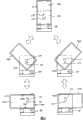
图6是示出使上壳体朝向下壳体倾斜的操作的简图。FIG. 6 is a diagram illustrating an operation of tilting the upper case toward the lower case.
在图6中,省略了对图5所示的电缆410和弹簧420等的示出,以使该图易于观察。In FIG. 6, illustration of the
在直立状态下,上壳体100A并不朝向下壳体100B倾斜(图6中的步骤S11),图5所示的弹簧420朝向下壳体100B弹性地向下推动上壳体100A,而上壳体100A相对于下壳体100B保持处于纵向姿态。另外,上壳体100A的下侧与邻接安装部201邻接,由此减小上壳体100A的摆动。In the upright state, the
在本实施例中,在图6的步骤S11所示的直立状态中,设计成使上壳体100A的宽度和中间部100C的宽度彼此相符合,并使突起310位于纵向槽210的最低位置。In this embodiment, in the upright state shown in step S11 of FIG.
当上壳体100A朝向左侧倾斜时,突起310在纵向槽210的引导下向上运动,从而使上壳体100A转动(图6中的步骤S12)。起初,通过图5所示的弹簧420,上壳体100A被朝向使其保持处于直立状态(图6中的步骤S11)的方向而弹性地推动。然而,当上壳体100A克服弹性推动力而进一步倾斜时,自从上壳体100A倾斜约45度的角度时,上壳体100A被朝向与转动方向相同的方向弹性地推动。因此,上壳体100A的左下角由邻接安装部201引导,并且突起310在纵向槽210的引导下向下运动,由此使上壳体100A转动(图6中的步骤S12),且相对于下壳体100B朝左侧向一边倒下(图6中的步骤S13)。When the
在步骤S13示出的朝左侧倒的状态中,上壳体100A的、与下壳体100B相对的面1001与邻接安装部201邻接,且上壳体100A由弹簧420弹性地向下推动,以保持其朝左侧倒的状态,从而降低在朝左侧倒的状态下的摆动。另外,在朝左侧倒的状态下,上壳体100A的右边缘1002与中间壳体100C的右边缘齐平,且上壳体100A的上边缘1003与中间壳体100C的上边缘齐平。In the state of falling to the left side shown in step S13, the
接着,当使用者从朝左侧倒的状态沿着向右的方向转动上壳体100A时(图6中的步骤S13),上壳体100A首先沿着使上壳体100A保持处于朝左侧倒状态的方向,由如图5所示的弹簧420弹性地推动。然而,随着上壳体100A接近直立状态时,上壳体100A被沿着与转动方向相同的方向弹性地推动。因此,上壳体100A在被邻接安装部201引导时转动,从而返回到直立状态。Next, when the user turns the
另一方面,当使用者沿着向右的方向使上壳体100A从直立状态(图6中的步骤S11)倾斜时(图6中的步骤S14),上壳体100A的突起310由纵向槽210引导,并且上壳体100A的右下角由邻接安装部201引导,由此使上壳体100A相对于下壳体100B朝右侧倒(图6中的步骤S15)。On the other hand, when the user tilts the
如上所述,根据本发明的手机,可以容易地使上壳体100A相对于下壳体100B向左与向右倾斜,而不需为上壳体100A的每个下角提供大的弯曲。这使得上壳体100A具有大液晶面板101,这样使其可以浏览以大尺寸显示的图像,同时保持手机的握持性。As described above, according to the mobile phone of the present invention, it is possible to easily tilt the
然后,将描述根据本发明的第二实施例。除了第二实施例的中间壳体100C的纵向槽210的长度不同于第一实施例外,第二实施例具有与第一实施例相同的结构。因此,在本实施例中,与第一实施例相同的部件采用相同的标记表示,并且省略对它们的描述。仅描述第二实施例与第一实施例的区别。Then, a second embodiment according to the present invention will be described. The second embodiment has the same structure as the first embodiment except that the length of the
图7是示出在根据本实施例的手机中,使上壳体朝向下壳体倾斜的操作的简图。FIG. 7 is a diagram showing an operation of tilting the upper case toward the lower case in the mobile phone according to the present embodiment.
根据本实施例的手机具有与根据图6所示的第一实施例的手机基本相同的构造,但是纵向槽210′比第一实施例的纵向槽210更长,且突起310设计成在图7的步骤S21所示的直立状态中,到达纵向槽210′的中间位置。The mobile phone according to this embodiment has substantially the same structure as the mobile phone according to the first embodiment shown in FIG. In the upright state shown in step S21, the middle position of the longitudinal groove 210' is reached.
当上壳体100A朝左侧倾斜时(图7中的步骤S22),如同第一实施例的情况,上壳体100A由图5所示的弹簧420弹性地向下推动,突起310由纵向槽210′引导且上壳体100A的左下角由邻接安装部201等引导。When the
在朝左侧倒状态下,上壳体100A已相对于下壳体100B朝左侧向一边倒下(图7中的步骤S23),上壳体100A的右边缘1004并不与中间壳体100C的右边缘1005齐平,且整个上壳体100A靠近中心位置,这不同于第一实施例中的朝左侧倒状态(图6中的步骤S13)。In the state of falling to the left, the
另外,当上壳体100A倾斜(图7中的步骤S24)并已相对于下壳体100B朝右侧完全向一边倒下时(图7中的步骤S25),上壳体100A的左边缘1006不与中间壳体100C的左边缘1007齐平,且上壳体100A靠近中心位置。In addition, when the
按照这种方式,当上壳体100A倾斜成朝左侧倒状态和朝右侧倒状态时,使整个上壳体100A靠近中心位置,这样就使得能够改进手机握持在手中时的稳定性的感觉。In this way, when the
现在将描绘根据本发明的第三实施例。由于除了第三实施例中的铰接部200的形状不同于第一实施例之外,第三实施例具有与第一实施例相同的构造,所以在此仅描述第三实施例与第一实施例的区别。A third embodiment according to the invention will now be described. Since the third embodiment has the same configuration as the first embodiment except that the shape of the
图8A和图8B分别是根据本实施例的手机的上壳体100A和中间壳体100C的主视图和侧视图,图9为根据本实施例的手机的上壳体100A和中间壳体100C的斜视图。8A and 8B are respectively a front view and a side view of the
如图8A和图8B所示,在本实施例中,凹陷部520设置在中间壳体100C的铰接部200的左右两端。凹陷部是本发明所称的“凹部”的一个实例。As shown in FIGS. 8A and 8B , in the present embodiment, recessed
如图9所示,凹陷部520为设置在上壳体100A和邻接安装部201之间的间隔。如上所述,当上壳体100A相对于下壳体100B倾斜大约45度时,上壳体100A在图5所示的弹簧420的弹性推动力的作用下,自动地转动至朝左侧倒状态和朝右侧倒状态。因此,使用者可以仅通过单手握持手机、将指尖伸入凹陷部520并向上推上壳体100A,而容易地使上壳体100A向一侧倒下。As shown in FIG. 9 , the recessed
接着,将描述根据本发明的第四实施例。在第四实施例中,与第一实施例相同的部件将采用相同的标记表示,并省略对它们的描述。仅描述第四实施例与第一实施例的区别。Next, a fourth embodiment according to the present invention will be described. In the fourth embodiment, the same components as those of the first embodiment will be denoted by the same symbols, and their descriptions will be omitted. Only the differences between the fourth embodiment and the first embodiment will be described.
图10A和图10B为各自示出根据本实施例的手机的透视图。10A and 10B are perspective views each showing a mobile phone according to the present embodiment.
图10A为从手机的前方观察时手机的透视图,图10B为从侧面观察时该手机的透视图。Figure 10A is a perspective view of the handset as viewed from the front of the handset, and Figure 10B is a perspective view of the handset as viewed from the side.
如同根据图5所示的第一实施例的手机的情况,在根据图10A和图10B所示的该实施例的手机中,上壳体100A由弹簧420弹性地向下推动,通过上壳体100A的突起310进入设置在中间壳体100C中的纵向槽210中,上壳体100A由中间壳体100C可转动地支撑。而且,在根据本实施例的手机中,通过使用者推动设置在左右两端的按钮611之一,上壳体100A沿左右方向中的相应一个方向转动。As in the case of the mobile phone according to the first embodiment shown in FIG. 5, in the mobile phone according to this embodiment shown in FIGS. The
图11A至图11C为各自示出图10的手机中的按钮611附近的放大图。11A to 11C are enlarged views each showing the vicinity of the
图11A是示出手机中的按钮附近的侧视图,图11B是从前方观察时的按钮611附近的透视图,且图11C是从侧面观察时的按钮611附近的剖视图。同时,根据本实施例的手机具有:左侧部件,用于使上壳体100A朝左侧倾斜;以及右侧部件,用于使上壳体100A朝右侧倾斜。然而,由于左侧部件和右侧部件具有相同的构造,所以在下文中仅描述左侧部件作为其代表。11A is a side view showing the vicinity of the button in the mobile phone, FIG. 11B is a perspective view of the vicinity of the
中间壳体100C包括:按压爪613,其从按钮611延伸;按压弹簧612,其朝向按钮611牵拉按压爪613;操作杆614,其通过由按压爪613推动而围绕轴616向下转动;片簧615,其弹性地向上推动操作杆614;锁定爪617,其连接到操作杆614的前端;可动爪618,其通过锁定爪617而被阻止运动;拉簧619,其沿轴616的方向牵拉可动爪618。上壳体100A包括安装孔(erection hole)621和侧倒孔622,当上壳体100A处于直立状态时可动爪618适配于该安装孔内,当上壳体100A处于朝左侧倒的状态时可动爪适配于该侧倒孔622中。The
在按钮611尚未被按压的状态下,可动爪618沿着轴616的方向(图11B中的右向)由拉簧619牵拉,但是可动爪618通过由锁定爪617锁定且进一步通过适配于上壳体100A的安装孔621中而被阻止运动。上壳体100A通过由图5所示的弹簧420弹性地向下推动而保持处于直立状态。In the state where the
图12A和图12B是示出按压(push)按钮611时的操作的简图,图13A和图13B及图14A和图14B是示出上壳体100A的转动操作的简图。12A and 12B are diagrams showing operations when the
当使用者按压按钮611时,如图12A和图12B所示,通过按压爪613推动操作杆614,操作杆614围绕轴616向下转动,且锁定爪617下落,由此解除阻止可动爪618运动的锁定。在解除锁定之后,在可动爪618适配于上壳体100A的安装孔621中的情况下,可动爪618沿着向右的方向由拉簧619牵拉。因此,如图13A和图13B所示,在保持直立状态的方向上(参看图5),由拉簧619施加的拉力A超过由弹簧420(参看图5)施加的弹性推动力B,由此在突起310由纵向槽210引导而向上运动时,上壳体100A向左转动。When the user presses the
在此,由于图12A所示的操作杆614由片簧615弹性地向上推动,通过推动按钮611,使操作杆614向下运动,从而解除锁定。因此,当可动爪618脱离(get over)锁定爪617时,操作杆614向上运动,按钮611返回到初始状态。Here, since the operating
当上壳体100A转动大约45度时,图12A所示的可动爪618从上壳体100A的安装孔621移位(displace),并不再施加用于沿向右的方向牵拉上壳体100A的力。然而,如图14A和图14B所示,弹簧420(参看图5)沿与转动方向相同的向下方向弹性地推动上壳体100A,并使上壳体100A转动至朝左侧倒状态。当上壳体100A转动至朝左侧倒状态时,可动爪618适配于上壳体100A的侧倒孔622中,由此阻止上壳体100A的运动。When the
按照这种方式,根据本实施例,使用者可以仅通过按压按钮611而容易地使上壳体100A倾斜。In this way, according to the present embodiment, the user can easily tilt the
当尝试使下壳体100A从朝左侧倒状态返回到直立状态时,使用者应当使上壳体100A向上滑动,随后使其沿向右的方向转动。于是,可动爪618从上壳体100A的侧倒孔622移位,由此克服拉簧619所施加的拉力而向左运动,在直立状态下,可动爪618适配于安装孔621中。When attempting to return the
现在将描述根据本发明的第五实施例。除了在第五实施例中,用于使上壳体100A自动倾斜的马达等设置在上壳体100A和下壳体100B中,第五实施例具有与第一实施例相同的构造,所以在此仅描述第五实施例与第一实施例的区别。A fifth embodiment according to the present invention will now be described. Except that in the fifth embodiment, a motor for automatically tilting the
图15A和图15B为各自示出根据本实施例的手机的上壳体的简图,图16是示出根据本实施例的手机的中间壳体的简图。15A and 15B are diagrams each showing an upper case of the mobile phone according to the present embodiment, and FIG. 16 is a diagram showing a middle case of the mobile phone according to the present embodiment.
如图15A和图15B所示,根据本实施例的手机具有与图4所示的第一实施例相同的突起310,且在上壳体100A的下侧还包括:小齿轮712;马达711,其用于可转动地驱动小齿轮712;以及倾斜按钮700,其用于使上壳体100A倾斜至相应的左向和右向。As shown in Figure 15A and Figure 15B, the mobile phone according to this embodiment has the
而且,如图16所示,根据本实施例的手机包括与图3所示的第一实施例相同的纵向槽210,以及与两个小齿轮相啮合的齿条720。Also, as shown in FIG. 16, the mobile phone according to this embodiment includes the same
图17是示出在根据本实施例的手机中使上壳体100A朝下壳体100B倾斜的操作的简图。FIG. 17 is a diagram showing an operation of tilting the
在本实施例中,在上壳体100A的直立状态下(图17中的步骤S31),突起310设置在纵向槽210的最低位置,且设置在上壳体100A中的两个小齿轮712与设置在中间壳体100C中的齿条720相啮合。In this embodiment, in the upright state of the
当使用者按压倾斜按钮700以使上壳体100A朝左侧倾斜时,驱动指令从CPU 110发送到马达711,且马达711被沿向右的方向可转动地驱动。因此,两个小齿轮712转动并沿着齿条720向右运动,且当右侧的小齿轮712从齿条720移位时,突起310由纵向槽210引导,左侧的小齿轮712也由纵向槽210引导,由此上壳体100A沿向左的方向转动(图17中的步骤S32)。When the user presses the
当上壳体100A沿向左的方向倾斜时,上壳体100A与邻接安装部201邻接,小齿轮712的运动停止(图17中的步骤S33)。When the
当使用者按压倾斜按钮700,以使上壳体100A朝右侧倾斜时,马达711被沿向左的方向可转动地驱动。因此,两个小齿轮712沿向左的方向运动,在左侧的小齿轮712已经从齿条720移位之后,上壳体100A沿向右的方向转动(图17中的步骤S34)。当上壳体100A倾斜至朝右侧倒状态时,小齿轮712的运动停止(图17中的步骤S35)。When the user presses the
如上所述,根据本实施例的手机,使用者可以在无需施加较大力的情况下,仅通过按压按钮611而容易地使上壳体100A倾斜。As described above, according to the mobile phone of the present embodiment, the user can easily tilt the
接下来,将描述根据本发明的第六实施例。同样,在第六实施例中,与第一实施例中的部件相同的部件采用相同的标记表示,并省略对它们的描述。仅描述第六实施例与第一实施例的区别。Next, a sixth embodiment according to the present invention will be described. Also, in the sixth embodiment, the same components as those in the first embodiment are denoted by the same symbols, and their descriptions are omitted. Only the differences between the sixth embodiment and the first embodiment will be described.
图18是示出根据本实施例的手机中的中间壳体100C的表面侧的简图。FIG. 18 is a diagram showing the surface side of the
如图18所示,与第一实施例的中间壳体100C相同,根据本实施例的中间壳体100C具有竖直延伸的纵向槽210;根据本实施例的中间壳体100C还具有形成于纵向槽210下方的、沿左右方向延伸的V形槽211。该V形槽是本发明所称的“导槽”的一个实例。As shown in FIG. 18, like the
图19是示出根据本实施例的手机中的上壳体100A的后表面侧的简图。FIG. 19 is a diagram showing the rear surface side of the
如图19所示,与图4所示的第一实施例中的上壳体100A的情况相同,上壳体100A具有适配于纵向槽210中的突起310;另外,上壳体100A还具有适配于V形槽211中的辅助突起312。辅助突起312是本发明所称的“导销”的一个实例。As shown in FIG. 19, same as the case of the
图20是示出上壳体100A、下壳体100B和中间壳体100C的透视图。FIG. 20 is a perspective view showing the
根据本发明的手机还具有弹簧420,该弹簧420连接到突起310并沿向下的方向弹性地推动上壳体100A。另外,在本实施例中,辅助突起312具有通孔,用于电连接上壳体100A和下壳体100B的电缆410设置成穿过辅助突起312的通孔。电缆410穿过辅助突起312的通孔,这同样能够防止电缆410断裂。The mobile phone according to the present invention also has a
图21A和图21B是示出根据本实施例的手机的各个尺寸的简图。21A and 21B are diagrams showing various dimensions of the mobile phone according to the present embodiment.
在根据本实施例的手机中,在图21A所示的朝左侧倒状态下,上壳体100A的右边缘与突起310的中心之间的距离B1等于上壳体100A的下边缘与辅助突起312的中心之间的距离B2;突起310的中心与辅助突起312的中心之间的距离C1等于在图21B所示的直立状态下突起310的中心与辅助突起312的中心之间的距离C2。另外,为了使上壳体100A平滑地转动,在上壳体100A的下边缘与邻接安装部201之间设有间隔A。通过使用具有此类尺寸的上壳体100A和中间壳体100C,在朝左侧倒的状态下可以使上壳体100A的右边缘与中间壳体100C的右边缘成一条直线,而在朝右侧倒的状态下可以使上壳体100A的左边缘与中间壳体100C的左边缘成一条直线。而且,在朝左侧倒与朝右侧倒两种状态下,可以使上壳体100A的上边缘与中间壳体100C的上边缘成一条直线。In the mobile phone according to the present embodiment, in the state of being tilted toward the left side shown in FIG. 21A , the distance B1 between the right edge of the
图22是示出使上壳体100A朝下壳体100B倾斜的操作的简图。FIG. 22 is a diagram showing an operation of tilting the
还是如图21B所示,当上壳体100A处于直立状态下(图22中的步骤41),突起310位于纵向槽210的最低位置,且辅助突起312位于V形槽211的最低位置。Also as shown in FIG. 21B , when the
当使用者使上壳体100A朝左侧倾斜时,首先,突起310在纵向槽210的引导下向上运动,辅助突起312也沿着V形槽211的右侧槽向上运动,上壳体100A克服弹簧420的弹性推动力而开始向左转动(图22中的步骤S42)。When the user tilts the
在转动大约45度时,上壳体100A由弹簧420沿着与转动方向相同的方向弹性地推动,上壳体100A转动同时其底角由邻接安装部201引导,从而相对于下壳体100B朝左侧倒(图22中的步骤43)。When turning about 45 degrees, the
另一方面,当使用者使上壳体100A朝右侧倾斜时(图22中的步骤S44),突起310由纵向槽210引导且辅助突起312由V形槽211的左侧槽引导,由此上壳体100A向右转动,且相对于下壳体100B朝右侧倒(图22中的步骤S45)。这样,在除纵向槽210之外设置V形槽211,就使得上壳体100A能更加平滑地倾斜。On the other hand, when the user tilts the
接着,将描述根据本发明的第七实施例。除了第七实施例中纵向槽210的尺寸不同于第六实施例之外,第七实施例与第六实施例的构造相同,因而仅描述第七实施例与第六实施例的区别。Next, a seventh embodiment according to the present invention will be described. Except that the size of the
图23A和图23B是示出根据本发明的该实施例的手机中的各个尺寸的简图。23A and 23B are diagrams showing various dimensions in the mobile phone according to the embodiment of the present invention.
在根据本实施例的手机中,在图23A所示的朝左侧倒状态下,当中间壳体100C的右边缘与上壳体100A的右边缘之间的距离表示为β,且突起310的中心与辅助突起312的中心之间的距离表示为J时,使上壳体100A的右边缘与突起310的中心之间的距离为H+β,在图23B所示的直立状态下突起310的中心与辅助突起312的中心之间的距离为(J-β)。而且,为了使上壳体100A平滑地转动,在上壳体100A的下边缘与邻接安装部201之间设有间隔D。形成具有此类尺寸的上壳体和中间壳体,使得可以在朝左侧倒状态和朝右侧倒状态下,使上壳体100A靠近中心位置,并提高使用者用手握持手机时的稳定性。In the mobile phone according to the present embodiment, in the state of being tilted toward the left side shown in FIG. 23A , when the distance between the right edge of the
图24是示出使上壳体100A朝下壳体100B倾斜的操作的简图。FIG. 24 is a diagram showing an operation of tilting the
还是如图23B所示,当上壳体100A处于直立状态时(图24中的步骤S51),突起310位于纵向槽210的中心位置,辅助突起312位于V形槽211的最低位置。Also as shown in FIG. 23B, when the
当使用者使上壳体100A朝左侧倾斜时,突起310由纵向槽210引导,辅助突起312由V形槽211的右侧槽引导并沿该右侧槽运动,由此上壳体100A向左转动(图24中的步骤S52)。When the user tilts the
当上壳体100A转动至朝左侧倒状态时(图24中的步骤S53),上壳体100A受到邻接安装部201的干涉,上壳体100A的运动停止。When the
另一方面,当使用者使上壳体100A朝右侧倾斜时(图24中的步骤S54),突起310由纵向槽210引导,辅助突起312由V形槽211的左侧槽引导并沿该左侧槽运动,由此上壳体100A向右转动并相对于下壳体100B朝左侧倒(图24中的步骤S55)。On the other hand, when the user tilts the
按照这种方式,根据本实施例的手机,当上壳体100A倾斜时,上壳体100A可以靠近中心位置。In this way, according to the mobile phone of the present embodiment, when the
现在将描述根据本发明的第八实施例。除了第八实施例中的上壳体与中间壳体之间的间隔尺寸不同于第七实施例之外,第八实施例的构造与第七实施例相同,因此仅描述第八实施例与第七实施例的区别。An eighth embodiment according to the present invention will now be described. Except that the distance between the upper case and the middle case in the eighth embodiment is different from that of the seventh embodiment, the structure of the eighth embodiment is the same as that of the seventh embodiment, so only the eighth embodiment and the seventh embodiment will be described. The difference of the seven embodiments.
图25A和图25B是示出根据本实施例的手机的各个尺寸的简图。25A and 25B are diagrams showing various dimensions of the mobile phone according to the present embodiment.
在根据本实施例的手机中,当处于图25A所示的朝左侧倒状态下的上壳体100A的右边缘与中间壳体100C的右边缘之间的距离表示为α,且突起310的中心与辅助突起312的中心之间的距离表示为F时,以及当处于图25B所示的直立状态下的上壳体100A的下边缘与邻接安装部201之间的距离表示为D时,使处于图25A所示的朝左侧倒状态下的上壳体100A的右边缘与突起310的中心之间的距离为(E+α),而在图25B所示的上壳体100A处于直立状态下,使突起310的中心与辅助突起312的中心之间的距离为F。根据本实施例的手机,当使上壳体100A倾斜至朝左侧倒状态或朝右侧倒状态时,可以使上壳体100A靠近中心位置并使上壳体100A升高。In the mobile phone according to the present embodiment, the distance between the right edge of the
接下来,将描述根据本发明的第九实施例。在本发明的第九实施例中,与第一实施例中的部件相同的部件采用相同的标记表示,且省略对它们的描述。仅描述第九实施例与第一实施例的区别。Next, a ninth embodiment according to the present invention will be described. In the ninth embodiment of the present invention, the same components as those in the first embodiment are denoted by the same symbols, and their descriptions are omitted. Only the differences between the ninth embodiment and the first embodiment will be described.
图26是示出根据本实施例的手机中的中间壳体100C的表面侧的简图。FIG. 26 is a diagram showing the surface side of the
如图26所示,与图3中的第一实施例的中间壳体100C的情况相同,本实施例的中间壳体100C具有竖直延伸的纵向槽210;另外,本实施例的中间壳体100C还具有朝下壳体100B延伸的辅助突起313。该辅助突起313也是本发明所称的“导销”的一个实例。As shown in FIG. 26, as in the case of the
图27是示出根据本实施例的手机的上壳体100A的后表面侧的简图。FIG. 27 is a diagram showing the rear surface side of the
与图4所示的第一实施例中的上壳体100A的情况相同,本实施例中的上壳体100A具有适配于纵向槽210中的突起310;另外,本实施例中的上壳体100A还具有弓形(arcuate)槽212,辅助突起313适配于该弓形槽中。弓形槽212的形状为使两侧对称的两个弧形槽在该弓形槽的中心连接。该弓形槽212也是本发明所称的“导槽”的一个实例。Same as the case of the
图28是示出使上壳体100A朝下壳体100B倾斜的操作的简图。FIG. 28 is a diagram showing an operation of tilting the
当上壳体100A处于直立状态时(图28中的步骤S61),突起310位于纵向槽210的最低位置,辅助突起313适配于弓形槽212的中心位置。When the
当使用者使上壳体100A朝左侧倾斜时,首先,突起310由纵向槽210引导以便竖直地运动,弓形槽212的左侧槽滑动,辅助突起313适配于该槽,由此上壳体100A向左转动(图28中的步骤S62)。When the user tilts the
在朝左侧倒状态下,上壳体100A相对于下壳体100B朝左侧倒下(图28中的步骤S63),突起310已经运动到纵向槽210的最低位置,且辅助突起313适配于弓形槽212的左侧槽的前端。In the state of falling to the left, the
另一方面,当使用者使上壳体100A朝右侧倾斜时(图28中的步骤S64),突起310由纵向槽210引导,弓形槽212的右侧槽滑动,辅助突起313适配于该槽中,由此上壳体100A向右转动(图28中的步骤S65)。如上所述,使用弓形槽取代V形槽,同样能使得上壳体100A平滑地倾斜。而且,使其中适配有辅助突起的槽滑动而不是使辅助突起沿着该槽运动,同样能使得上壳体100A转动。On the other hand, when the user tilts the
在上文中,已经描述了这些实例,其中根据本发明的移动终端装置应用于手机,但是根据本发明的移动终端装置可以应用于个人数字助理(PDA)等。In the above, examples have been described in which the mobile terminal device according to the present invention is applied to a cell phone, but the mobile terminal device according to the present invention may be applied to a personal digital assistant (PDA) or the like.
另外,在上面的说明中,已经描述了这些实例,其中纵向槽设置在中间壳体中且突起设置在上壳体中。然而,本发明所称的竖直槽可以设置在上壳体中而非中间壳体中,且本发明所称的突起可以设置在中间壳体中而非上壳体中。Also, in the above description, examples have been described in which the longitudinal groove is provided in the middle case and the protrusion is provided in the upper case. However, the vertical groove referred to in the present invention may be provided in the upper case instead of the middle case, and the protrusion referred to in the present invention may be provided in the middle case instead of the upper case.
另外,本发明所称的铰接部可以与中间壳体或下壳体构造为一体,或可选地,可以构造成独立于该壳体的铰接模块。In addition, the hinge part referred to in the present invention may be integrally constructed with the middle casing or the lower casing, or alternatively, may be constructed as a hinge module independent of the casing.
Claims (14)
Translated fromChineseApplications Claiming Priority (3)
| Application Number | Priority Date | Filing Date | Title |
|---|---|---|---|
| JP2007-033702 | 2007-02-14 | ||
| JP2007033702 | 2007-02-14 | ||
| JP2007033702AJP4973221B2 (en) | 2007-02-14 | 2007-02-14 | Mobile terminal device |
Publications (2)
| Publication Number | Publication Date |
|---|---|
| CN101247423A CN101247423A (en) | 2008-08-20 |
| CN101247423Btrue CN101247423B (en) | 2011-06-01 |
Family
ID=39686296
Family Applications (1)
| Application Number | Title | Priority Date | Filing Date |
|---|---|---|---|
| CN2008100056389AExpired - Fee RelatedCN101247423B (en) | 2007-02-14 | 2008-02-14 | Mobile terminal device |
Country Status (4)
| Country | Link |
|---|---|
| US (1) | US7925312B2 (en) |
| JP (1) | JP4973221B2 (en) |
| KR (1) | KR101006646B1 (en) |
| CN (1) | CN101247423B (en) |
Families Citing this family (26)
| Publication number | Priority date | Publication date | Assignee | Title |
|---|---|---|---|---|
| JP2006222735A (en)* | 2005-02-10 | 2006-08-24 | Sharp Corp | Communication equipment |
| US7991441B2 (en)* | 2006-11-23 | 2011-08-02 | Samsung Electronics Co., Ltd | Swing hinge device of a portable terminal and dual hinge device having the same |
| JP2009264460A (en)* | 2008-04-24 | 2009-11-12 | Sony Ericsson Mobilecommunications Japan Inc | Two-shaft hinge device, and portable terminal device |
| USD597999S1 (en)* | 2008-09-18 | 2009-08-11 | Samsung Electronics Co., Ltd. | Portable phone |
| WO2010035307A1 (en)* | 2008-09-24 | 2010-04-01 | 富士通株式会社 | Personal digital assistant |
| CN101750698A (en)* | 2008-12-10 | 2010-06-23 | 深圳富泰宏精密工业有限公司 | Lens module and electronic device applying lens module |
| US20100186234A1 (en) | 2009-01-28 | 2010-07-29 | Yehuda Binder | Electric shaver with imaging capability |
| JP4691697B2 (en) | 2009-01-27 | 2011-06-01 | Necカシオモバイルコミュニケーションズ株式会社 | Electronic device and program |
| CN101959381B (en)* | 2009-07-13 | 2015-06-03 | 深圳富泰宏精密工业有限公司 | Portable electronic device |
| TWI476565B (en)* | 2009-08-10 | 2015-03-11 | Chi Mei Comm Systems Inc | Portable electronic device |
| TWI372333B (en)* | 2009-11-11 | 2012-09-11 | Htc Corp | Handheld electronic device |
| JP5375578B2 (en)* | 2009-12-15 | 2013-12-25 | 富士通株式会社 | Electronics |
| JP5272269B2 (en)* | 2010-07-09 | 2013-08-28 | 日本電気株式会社 | Electronic device and program |
| EP2477091A1 (en)* | 2011-01-10 | 2012-07-18 | Research In Motion Limited | Keyboard with rotatable portion |
| US8662769B2 (en) | 2011-01-10 | 2014-03-04 | Research In Motion Limited | Keyboard with rotatable portion |
| USD921637S1 (en) | 2019-11-22 | 2021-06-08 | Fintie Llc | Case for electronic device with pencil holder |
| USD909391S1 (en) | 2019-12-02 | 2021-02-02 | Fintie Llc | Case for electronic device with multi-angle stand cover |
| USD922391S1 (en) | 2020-01-27 | 2021-06-15 | Fintie Llc | Case for electronic device with detachable keyboard |
| USD922390S1 (en) | 2020-01-27 | 2021-06-15 | Fintie Llc | Case for electronic device with multi-angle stand cover |
| USD923011S1 (en) | 2020-02-19 | 2021-06-22 | Fintie Llc | Stand cover for electronic device |
| USD980225S1 (en) | 2020-02-19 | 2023-03-07 | Fintie Llc | Protective case for electronic device |
| USD942982S1 (en) | 2020-06-22 | 2022-02-08 | Fintie Llc | Case for electronic device with multi-angle rotatable stand |
| USD940723S1 (en) | 2020-07-09 | 2022-01-11 | Fintie Llc | Case for electronic device with multi-angle stand |
| USD991936S1 (en) | 2020-08-31 | 2023-07-11 | Fintie Llc | Case for electronic device with flexible multi-configuration stand |
| CN116235235A (en)* | 2020-11-06 | 2023-06-06 | 三星电子株式会社 | Electronic equipment including heat dissipation components |
| USD986251S1 (en) | 2021-09-20 | 2023-05-16 | Fintie Llc | Stand cover for electronic device |
Citations (4)
| Publication number | Priority date | Publication date | Assignee | Title |
|---|---|---|---|---|
| CN1503566A (en)* | 2002-11-20 | 2004-06-09 | 日本电气株式会社 | Mobile terminal and posture detecting method thereof |
| CN1536855A (en)* | 2003-04-09 | 2004-10-13 | �ձ�������ʽ���� | Movable terminal |
| CN1765109A (en)* | 2003-03-26 | 2006-04-26 | 索尼爱立信移动通讯股份有限公司 | Clamshell-type mobile terminal with a better access to input keys |
| JP2006186655A (en)* | 2004-12-27 | 2006-07-13 | Sony Corp | Mobile terminal device |
Family Cites Families (23)
| Publication number | Priority date | Publication date | Assignee | Title |
|---|---|---|---|---|
| CA2051442C (en)* | 1990-02-27 | 1995-07-18 | Hisamitsu Takagi | Portable telephone |
| JP3737160B2 (en)* | 1995-03-31 | 2006-01-18 | 富士通株式会社 | Folding mobile phone hinge mechanism and folding mobile phone |
| JP3739641B2 (en)* | 2000-04-19 | 2006-01-25 | 富士通株式会社 | Folding portable machine |
| KR20000064177A (en)* | 2000-05-01 | 2000-11-06 | 권용순 | mobile station |
| KR100438433B1 (en)* | 2001-06-26 | 2004-07-03 | 삼성전자주식회사 | Combination device with portable radiotelephone/personal digital assistant/digital camera assembly |
| JP2003249985A (en)* | 2002-02-22 | 2003-09-05 | Matsushita Electric Ind Co Ltd | Foldable mobile communication terminal |
| JP4061473B2 (en)* | 2002-04-26 | 2008-03-19 | 日本電気株式会社 | Folding mobile phone |
| FI118668B (en)* | 2003-04-01 | 2008-01-31 | Samsung Electro Mech | Mobile phone and its automatic rotation method |
| US7450977B2 (en)* | 2003-07-31 | 2008-11-11 | Vodafone K.K. | Mobile communication terminal |
| JP4187607B2 (en)* | 2003-08-14 | 2008-11-26 | 富士通株式会社 | Mobile wireless communication device |
| KR100563724B1 (en)* | 2003-08-22 | 2006-03-28 | 엘지전자 주식회사 | Foldable mobile communication terminal with 2-axis rotary hinge module |
| KR100557078B1 (en)* | 2003-11-06 | 2006-03-03 | 삼성전자주식회사 | Hinge device for display rotatable mobile terminal |
| KR100834626B1 (en)* | 2004-05-06 | 2008-06-02 | 삼성전자주식회사 | Sliding/swing type portable device with self-cradling |
| CN100502624C (en)* | 2004-08-27 | 2009-06-17 | 深圳富泰宏精密工业有限公司 | hinge structure |
| WO2006038554A1 (en)* | 2004-10-01 | 2006-04-13 | Sharp Kabushiki Kaisha | Mobile information terminal |
| JP4203476B2 (en)* | 2005-01-24 | 2009-01-07 | シャープ株式会社 | Portable information device |
| JP4384059B2 (en)* | 2005-01-31 | 2009-12-16 | シャープ株式会社 | Folding cell phone |
| KR20060095310A (en) | 2005-02-28 | 2006-08-31 | 주식회사 팬택앤큐리텔 | Semi-automatic swing module and mobile communication terminal equipped with the swing module |
| KR100689530B1 (en)* | 2005-03-16 | 2007-03-02 | 삼성전자주식회사 | Mobile phone with replaceable module |
| KR100652718B1 (en)* | 2005-04-04 | 2006-12-01 | 엘지전자 주식회사 | Gear-driven slide module of mobile communication terminal and its opening and closing method |
| US7414834B2 (en)* | 2005-04-21 | 2008-08-19 | Nokia Corporation | Mobile communications device with synchronising hinge |
| KR100788995B1 (en)* | 2005-08-10 | 2007-12-28 | 주식회사 팬택 | Mobile terminal with additional keypad |
| JP4638403B2 (en)* | 2006-11-09 | 2011-02-23 | 株式会社山本精密 | Slide / rotary mounting unit and electronic equipment |
- 2007
- 2007-02-14JPJP2007033702Apatent/JP4973221B2/ennot_activeExpired - Fee Related
- 2008
- 2008-02-12USUS12/029,654patent/US7925312B2/ennot_activeExpired - Fee Related
- 2008-02-13KRKR1020080012967Apatent/KR101006646B1/ennot_activeExpired - Fee Related
- 2008-02-14CNCN2008100056389Apatent/CN101247423B/ennot_activeExpired - Fee Related
Patent Citations (4)
| Publication number | Priority date | Publication date | Assignee | Title |
|---|---|---|---|---|
| CN1503566A (en)* | 2002-11-20 | 2004-06-09 | 日本电气株式会社 | Mobile terminal and posture detecting method thereof |
| CN1765109A (en)* | 2003-03-26 | 2006-04-26 | 索尼爱立信移动通讯股份有限公司 | Clamshell-type mobile terminal with a better access to input keys |
| CN1536855A (en)* | 2003-04-09 | 2004-10-13 | �ձ�������ʽ���� | Movable terminal |
| JP2006186655A (en)* | 2004-12-27 | 2006-07-13 | Sony Corp | Mobile terminal device |
Also Published As
| Publication number | Publication date |
|---|---|
| CN101247423A (en) | 2008-08-20 |
| US7925312B2 (en) | 2011-04-12 |
| JP2008199385A (en) | 2008-08-28 |
| KR101006646B1 (en) | 2011-01-10 |
| KR20080076765A (en) | 2008-08-20 |
| JP4973221B2 (en) | 2012-07-11 |
| US20080194303A1 (en) | 2008-08-14 |
Similar Documents
| Publication | Publication Date | Title |
|---|---|---|
| CN101247423B (en) | Mobile terminal device | |
| US7916473B2 (en) | Portable terminal | |
| JP4405490B2 (en) | Mobile communication terminal | |
| US7632025B2 (en) | Mobile communication terminal having rotatable camera | |
| US8358513B2 (en) | Expansion module for mobile device and mobile device having the same | |
| US8396520B2 (en) | Portable terminal having a slide module with a tilting unit | |
| JP4663925B2 (en) | Foldable portable electronic device and handle device for foldable portable electronic device | |
| US8576549B2 (en) | Two-axis hinge and mobile device | |
| EP2665240B1 (en) | Mobile terminal including a sliding door for a socket | |
| JP2004215180A (en) | Portable radio terminal | |
| US7366550B2 (en) | Handheld electronic apparatus | |
| JP2004235687A (en) | Portable radio terminal | |
| KR100800711B1 (en) | Free stop hinge device of mobile terminal | |
| JP4210288B2 (en) | Portable wireless terminal | |
| EP3851936B1 (en) | Foldable multimedia terminal | |
| JP4252021B2 (en) | Mobile phone | |
| KR102215610B1 (en) | Folding multimedia terminal | |
| JP3874750B2 (en) | Foldable mobile terminal with slide function | |
| JP4974079B2 (en) | Foldable communication terminal | |
| CN101019409A (en) | Mobile device | |
| KR20060074289A (en) | Sliding Mobile Communication Terminal | |
| KR20060073291A (en) | Mobile terminal with rotary microphone set | |
| JP2007194849A (en) | Mobile electronic apparatus |
Legal Events
| Date | Code | Title | Description |
|---|---|---|---|
| C06 | Publication | ||
| PB01 | Publication | ||
| C10 | Entry into substantive examination | ||
| SE01 | Entry into force of request for substantive examination | ||
| C14 | Grant of patent or utility model | ||
| GR01 | Patent grant | ||
| CF01 | Termination of patent right due to non-payment of annual fee | Granted publication date:20110601 Termination date:20190214 | |
| CF01 | Termination of patent right due to non-payment of annual fee |