CN101244296B - Artificial heart blood pump suspended by hybrid magnetic force and hydrodynamic pressure - Google Patents
Artificial heart blood pump suspended by hybrid magnetic force and hydrodynamic pressureDownload PDFInfo
- Publication number
- CN101244296B CN101244296BCN2008101023861ACN200810102386ACN101244296BCN 101244296 BCN101244296 BCN 101244296BCN 2008101023861 ACN2008101023861 ACN 2008101023861ACN 200810102386 ACN200810102386 ACN 200810102386ACN 101244296 BCN101244296 BCN 101244296B
- Authority
- CN
- China
- Prior art keywords
- blood
- dynamic pressure
- tail
- head
- bearing
- Prior art date
- Legal status (The legal status is an assumption and is not a legal conclusion. Google has not performed a legal analysis and makes no representation as to the accuracy of the status listed.)
- Expired - Fee Related
Links
- 210000004369bloodAnatomy0.000titleclaimsabstractdescription107
- 239000008280bloodSubstances0.000titleclaimsabstractdescription107
- 239000000725suspensionSubstances0.000claimsabstractdescription75
- 239000011229interlayerSubstances0.000claimsdescription4
- 239000000203mixtureSubstances0.000claims8
- 230000015572biosynthetic processEffects0.000claims2
- 230000000004hemodynamic effectEffects0.000abstractdescription22
- 239000012530fluidSubstances0.000abstractdescription8
- 230000017531blood circulationEffects0.000abstractdescription7
- 206010018910HaemolysisDiseases0.000abstractdescription3
- 210000003743erythrocyteAnatomy0.000abstractdescription3
- 230000008588hemolysisEffects0.000abstractdescription3
- 238000010008shearingMethods0.000abstractdescription3
- 238000010586diagramMethods0.000description6
- 239000010410layerSubstances0.000description6
- 238000005461lubricationMethods0.000description4
- 239000006194liquid suspensionSubstances0.000description3
- 238000004519manufacturing processMethods0.000description3
- 208000007536ThrombosisDiseases0.000description2
- 229910001069Ti alloyInorganic materials0.000description2
- 238000007667floatingMethods0.000description2
- 238000005339levitationMethods0.000description2
- 239000007788liquidSubstances0.000description2
- 238000000034methodMethods0.000description2
- 238000005086pumpingMethods0.000description2
- 238000007789sealingMethods0.000description2
- 230000002861ventricularEffects0.000description2
- 230000009286beneficial effectEffects0.000description1
- 230000036770blood supplyEffects0.000description1
- 210000004204blood vesselAnatomy0.000description1
- 230000002949hemolytic effectEffects0.000description1
- 238000009434installationMethods0.000description1
- 239000000463materialSubstances0.000description1
- 238000002560therapeutic procedureMethods0.000description1
- 239000002699waste materialSubstances0.000description1
Images


Landscapes
- External Artificial Organs (AREA)
- Structures Of Non-Positive Displacement Pumps (AREA)
Abstract
Translated fromChinese
Description
Translated fromChinese技术领域technical field
本发明涉及一种辅助心脏内血液流动的血液泵,尤指一种磁力与流体动压混合悬浮的人工心脏血液泵。The invention relates to a blood pump for assisting blood flow in the heart, in particular to an artificial heart blood pump which is suspended by mixing magnetic force and fluid dynamic pressure.
背景技术Background technique
人工心脏主要有心室辅助血液泵和全人工心脏,从泵血原理分主要有叶轮泵和搏动泵。由于叶轮血泵具有体积小、效率高等特点,所以,叶轮血泵是目前人工心室辅助治疗装置的研究热点。传统叶轮泵,由于旋转部件的润滑和密封对血泵的寿命和血液兼容性造成影响,现阶段国际上主要流行的解决方案是使用无需润滑的轴承、运用磁悬浮转子或液浮转子。但是,如外轴承式人工心脏血液泵(专利号200610002894)解决了上述密封和润滑问题,但是其原理上泵血效率低,大比例的能源浪费会成为其难走上临床的障碍;磁悬浮转子血泵(申请号200710039971.7)直径大、剪切力大,对于血液有形成分,特别是血红细胞的破坏相当大,由此造成的溶血性能问题无法克服,其轴流式实施例由于间隙过小,无法达到血泵的供血流量要求;液动压轴承血泵(US2004236420A1),形状复杂,死角过多、液浮结构面积大,使血液接触异物时间大,增加了血栓产生的机会。Artificial hearts mainly include ventricular auxiliary blood pumps and total artificial hearts. From the principle of blood pumping, there are mainly impeller pumps and pulsating pumps. Because the impeller blood pump has the characteristics of small size and high efficiency, the impeller blood pump is currently a research hotspot of the artificial ventricular assisting therapy device. For traditional impeller pumps, since the lubrication and sealing of rotating parts affect the life and blood compatibility of the blood pump, the main popular solutions in the world at this stage are to use non-lubricated bearings, magnetic levitation rotors or liquid floating rotors. However, such as the external bearing type artificial heart blood pump (Patent No. 200610002894) solves the above-mentioned sealing and lubrication problems, but in principle, the blood pumping efficiency is low, and a large proportion of energy waste will become an obstacle to its clinical application; The pump (Application No. 200710039971.7) has a large diameter and a large shearing force, which can greatly damage the formed components of blood, especially red blood cells. The hemolytic performance problem caused by this cannot be overcome. The axial flow embodiment of the pump has too small a gap. The blood supply flow requirement of the blood pump cannot be met; the hydrodynamic bearing blood pump (US2004236420A1) has a complex shape, too many dead ends, and a large area of the liquid floating structure, which makes the time of blood contacting foreign objects longer and increases the chance of thrombus generation.
发明内容Contents of the invention
本发明的目的是提供一种磁力与流体动压混合悬浮人工心脏血液泵,以解决人工心脏血液泵润滑问题、形状复杂、血液破坏严重等问题。The purpose of the present invention is to provide a magnetic force and fluid dynamic pressure mixed suspension artificial heart blood pump to solve the problems of artificial heart blood pump lubrication, complex shape, serious blood damage and the like.
为了实现上述目的,本发明采取了如下技术方案。一种磁力与流体动压混合悬浮的人工心脏血液泵,由含有电机定子8的外壳7套在含有头支撑组件1、转子组件、尾支撑组件15的内壳9上构成,其特征在于:转子组件、头支撑组件1和尾支撑组件15装配在圆柱形内壳9中,转子组件撑架在头支撑组件1和尾支撑组件15之间,从而构成血液动压悬浮结构;其中,所述的头支撑组件1的中心为头部血液动压悬浮锥轴承2;所述的转子组件依次由头部血液动压悬浮锥3、叶轮6、尾部永磁轴承内环10、尾部血液动压悬浮锥13构成;所述的尾支撑组件15的中心为尾部血液动压悬浮锥轴承14,且轴承外侧嵌有尾部永磁轴承外环12。尾部永磁轴承内环10和尾部永磁轴承外环12组成的尾部动磁悬浮结构,使血泵转子组件在高速旋转时可以实现动态自动平衡。In order to achieve the above object, the present invention adopts the following technical solutions. An artificial heart blood pump with mixed suspension of magnetic force and hydrodynamic pressure is composed of an
本装置为了便于放置于血管中,本装置的外壳7为圆柱形,与内壳9形成夹层,电机定子8位于夹层内,外壳7一端通过侧板与内壳9密封连接,另一端通过端盖11与内壳9密封连接。In order to facilitate the placement of the device in the blood vessel, the
为了使血液流动平稳,在本装置的头支撑组件1和尾支撑组件15中,在头部血液动压悬浮锥轴承2周围和尾部血液动压悬浮锥轴承14周围均设置有均匀阵列分布的头部导流叶片5和尾部导流叶片16,其中尾部导流叶片16采用与叶轮6旋转方向相反的螺旋状叶片;另外,在尾支撑组件15的尾部,即在轴承后面,设置有尾导流锥17。In order to make the blood flow stable, in the head support assembly 1 and the
为了使血液受到较小的破坏,转子组件中的叶轮6的轮轴直径比较小,且叶轮6中叶片的厚度比较小。In order to make the blood less damaged, the diameter of the shaft of the
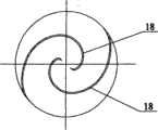
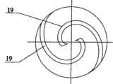
为了易于产生动压液悬浮层,且不影响血液流动,在转子组件中的头部血液动压悬浮锥3和尾部血液动压悬浮锥13的锥面上分别开有双螺旋结构的头部血液动压悬浮锥血液槽18和尾部血液动压悬浮锥血液槽19,并且头部血液动压悬浮锥血液槽18和尾部血液动压悬浮锥血液槽19的螺旋方向相反。In order to easily generate the dynamic pressure liquid suspension layer without affecting the blood flow, the head blood dynamic
本发明的有益效果是:1)由于本发明为磁力与流体动压混合悬浮轴承,所以,轴承便于润滑,无磨损,且轴承的运转更加稳定、可靠。2)本装置中血液受到的剪切力比较小,对血红细胞的破坏小,使溶血机会减少。3)由于本发明的支撑组件为环形和锥形,且叶轮6的轮轴直径易于做得足够小,叶轮6中叶片的厚度易于做得足够薄,因此便于加工制造、安装,且制造成本低。4)本发明的结构简单、无流场死角,因此不易产生血栓。The beneficial effects of the present invention are: 1) Since the present invention is a suspension bearing mixed with magnetic force and hydrodynamic pressure, the bearing is easy to lubricate, has no wear, and the operation of the bearing is more stable and reliable. 2) The shearing force on the blood in the device is relatively small, and the damage to the red blood cells is small, so that the chance of hemolysis is reduced. 3) Since the support assembly of the present invention is annular and conical, and the axle diameter of the
附图说明Description of drawings
图1为本发明磁力与流体动压混合悬浮人工心脏血液泵结构示意图Fig. 1 is a schematic diagram of the structure of the magnetic force and fluid dynamic pressure mixed suspension artificial heart blood pump of the present invention
图2为头部血液动压悬浮锥与头部血液动压悬浮动压悬浮锥轴承配合示意图Figure 2 is a schematic diagram of cooperation between the head blood dynamic pressure suspension cone and the head blood dynamic pressure suspension dynamic pressure suspension cone bearing
图3头部血液动压悬浮锥血液槽形状示意图Figure 3 Schematic diagram of the shape of the blood groove of the head blood dynamic pressure suspension cone
图4为尾部血液动压悬浮锥与尾部血液动压悬浮锥轴承配合示意图Figure 4 is a schematic diagram of the cooperation between the tail hemodynamic suspension cone and the tail hemodynamic suspension cone bearing
图5尾部血液动压悬浮锥血液槽形状示意图Figure 5 Schematic diagram of the shape of the blood groove of the tail blood dynamic pressure suspension cone
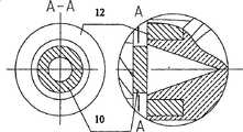
图6为尾部永磁轴承内环、尾部永磁轴承外环的相对关系示意图Figure 6 is a schematic diagram of the relative relationship between the inner ring of the tail permanent magnetic bearing and the outer ring of the tail permanent magnetic bearing
图中:1、头支撑组件,2、头部血液动压悬浮锥轴承,3、头部血液动压悬浮锥,4、过盈连接轴,5、头部导流叶片,6、转子组件,7、外壳,8、电机定子,9、内壳,10、尾部永磁轴承内环,11、端盖,12、尾部永磁轴承外环,13、尾部血液动压悬浮动压悬浮锥,14、尾部血液动压悬浮动压悬浮锥轴承,15、尾支撑组件,16、尾部导流叶片,17、尾导流锥。18、头部血液动压悬浮锥血液槽,19、尾部血液动压悬浮锥血液槽。In the figure: 1. Head support assembly, 2. Head hemodynamic pressure suspension cone bearing, 3. Head hemodynamic pressure suspension cone, 4. Interference connecting shaft, 5. Head guide vanes, 6. Rotor assembly, 7. Shell, 8. Motor stator, 9. Inner shell, 10. Inner ring of permanent magnetic bearing at tail, 11. End cover, 12. Outer ring of permanent magnetic bearing at tail, 13. Blood dynamic pressure suspension and dynamic pressure suspension cone at tail, 14 1. Tail blood dynamic pressure suspension dynamic pressure suspension cone bearing, 15. tail support assembly, 16. tail guide vane, 17. tail guide cone. 18. Head blood dynamic pressure suspension cone blood tank, 19. Tail blood dynamic pressure suspension cone blood tank.
具体实施方式Detailed ways
如图1所示,本发明公开的磁力与流体动压混合悬浮人工心脏血液泵主要包括外壳7和内壳9两部分,外壳7和内壳9皆为圆筒状,采用医用钛合金TC4材料制作。外壳7套在内壳9外形成夹层,夹层内放置电机定子8;外壳7一端用环形侧板与内壳9密封连接,另一端通过环形端盖11与内壳9密封连接。内壳9依次放置头支撑组件1、转子组件和尾支撑组件15,转子组件撑架在头支撑组件1和尾支撑组件15之间。其中,头支撑组件1由头部血液动压悬浮锥轴承2和头部导流叶片5构成,头部血液动压悬浮锥轴承2位于头支撑组件1的中心;头部导流叶片5均匀排列于头部血液动压悬浮锥轴承2的外围;轴承与内壳9间有使血液流通的孔道。转子组件依次由头部血液动压悬浮锥3、叶轮6、尾部永磁轴承内环10、尾部血液动压悬浮锥13构成,以上各部件由通过各部件中心的过盈连接轴4依次连接为一体;在头部血液动压悬浮锥3和尾部血液动压悬浮锥13的锥面上分别开有螺旋状的头部血液动压悬浮锥血液槽18和尾部血液动压悬浮锥血液槽19,且头部血液动压悬浮锥血液槽18和尾部血液动压悬浮锥血液槽19的螺旋方向相反;如图3、图5;转子组件中的叶轮6内按常规方式均匀嵌有永磁体,当电极定子与电源接通时与电极定子作用使转子组件转动;转子组件中的叶轮6采用医用钛合金TC4材料制作,叶轮6的轮轴直径小于叶轮6本身直径的一半,且叶轮6中叶片的厚度不超过1毫米。尾支撑组件15由尾部血液动压悬浮锥轴承14、尾部永磁轴承外环12、尾部导流叶片16和尾导流锥17组成,尾部血液动压悬浮锥轴承14位于尾支撑组件15的中心,在尾部血液动压悬浮锥轴承14的外侧嵌套有尾部永磁轴承外环12;尾部导流叶片16均匀排列于尾部血液动压悬浮锥轴承14的外围,且轴承的后面为尾导流锥17,轴承与内壳9间有使血液流通的孔道。As shown in Figure 1, the artificial heart blood pump disclosed by the present invention mainly includes an
本发明介绍的由头支撑组件1和尾支撑组件15构成的血液动压悬浮结构以及由尾部永磁轴承内环10和尾部永磁轴承外环12组成的尾部磁悬浮结构,使血泵转子组件在高速旋转时可以实现动态自动平衡。接通电机定子电源后,本发明介绍的头部血液动压悬浮锥3在转动时将血液沿其导流槽推进到头部血液动压悬浮锥轴承2内部并产生高压区,血液再沿头部血液动压悬浮锥3与头部血液动压悬浮锥轴承2之间的间隙流出,在此产生动压液悬浮层(如图2),该动压液悬浮层对转子组件产生轴向及径向的悬浮力;同样的,尾部血液动压悬浮锥13在转动时将血液沿其导流槽推进到尾部血液动压悬浮锥轴承14内部并产生高压区,血液再沿尾部血液动压悬浮锥13与尾部血液动压悬浮锥轴承14之间的间隙流出,在此产生动压液悬浮层(如图4),该动压液悬浮层对转子组件产生轴向及径向的悬浮力;本发明介绍的尾部永磁轴承内环10与尾部永磁轴承外环12(如图6),反向充磁,其作用在于血泵系统启动前产生向前的轴向磁力,使转子组件在该力的作用下被推向头部,使得头支撑组件1间隙小容易在启动过程中的低转速状态下形成动压液悬浮层,使转子组件快速实现悬浮,当在启动后,转子组件受到的向前的轴向血液流作用力和轴向磁力,造成尾支撑组件15的间隙变大,此时通过尾部永磁轴承内环10和尾部永磁轴承外环12在高速相对旋转运动状态下在径向和轴向产生永磁悬浮轴承力,弥补尾支撑组件15因间隙变大造成的液浮力损失。The blood dynamic pressure suspension structure composed of the head support assembly 1 and the
本装置工作时,血液首先流经头部导流叶片5,然后流到转子组件处,转子组件在电机定子8的作用下,通过叶轮6的旋转,将血液向后推进,血液流经尾支撑组件15,由尾部导流叶片16和尾导流锥17整流后流出内壳9。When the device works, the blood first flows through the
本发明的头支撑组件1、尾支撑组件15、尾部永磁轴承内环10和尾部永磁轴承外环12的直径可以做得很小,因此剪切力小,使溶血机会减少;本发明中的各部件也便于加工制造和安装;并且本发明中的轴承便于润滑。The diameter of the head support assembly 1 of the present invention, the
Claims (8)
Priority Applications (1)
| Application Number | Priority Date | Filing Date | Title |
|---|---|---|---|
| CN2008101023861ACN101244296B (en) | 2008-03-21 | 2008-03-21 | Artificial heart blood pump suspended by hybrid magnetic force and hydrodynamic pressure |
Applications Claiming Priority (1)
| Application Number | Priority Date | Filing Date | Title |
|---|---|---|---|
| CN2008101023861ACN101244296B (en) | 2008-03-21 | 2008-03-21 | Artificial heart blood pump suspended by hybrid magnetic force and hydrodynamic pressure |
Publications (2)
| Publication Number | Publication Date |
|---|---|
| CN101244296A CN101244296A (en) | 2008-08-20 |
| CN101244296Btrue CN101244296B (en) | 2010-06-16 |
Family
ID=39945118
Family Applications (1)
| Application Number | Title | Priority Date | Filing Date |
|---|---|---|---|
| CN2008101023861AExpired - Fee RelatedCN101244296B (en) | 2008-03-21 | 2008-03-21 | Artificial heart blood pump suspended by hybrid magnetic force and hydrodynamic pressure |
Country Status (1)
| Country | Link |
|---|---|
| CN (1) | CN101244296B (en) |
Cited By (11)
| Publication number | Priority date | Publication date | Assignee | Title |
|---|---|---|---|---|
| US10722631B2 (en) | 2018-02-01 | 2020-07-28 | Shifamed Holdings, Llc | Intravascular blood pumps and methods of use and manufacture |
| US11185677B2 (en) | 2017-06-07 | 2021-11-30 | Shifamed Holdings, Llc | Intravascular fluid movement devices, systems, and methods of use |
| US11511103B2 (en) | 2017-11-13 | 2022-11-29 | Shifamed Holdings, Llc | Intravascular fluid movement devices, systems, and methods of use |
| US11654275B2 (en) | 2019-07-22 | 2023-05-23 | Shifamed Holdings, Llc | Intravascular blood pumps with struts and methods of use and manufacture |
| US11724089B2 (en) | 2019-09-25 | 2023-08-15 | Shifamed Holdings, Llc | Intravascular blood pump systems and methods of use and control thereof |
| US11964145B2 (en) | 2019-07-12 | 2024-04-23 | Shifamed Holdings, Llc | Intravascular blood pumps and methods of manufacture and use |
| US12102815B2 (en) | 2019-09-25 | 2024-10-01 | Shifamed Holdings, Llc | Catheter blood pumps and collapsible pump housings |
| US12121713B2 (en) | 2019-09-25 | 2024-10-22 | Shifamed Holdings, Llc | Catheter blood pumps and collapsible blood conduits |
| US12161857B2 (en) | 2018-07-31 | 2024-12-10 | Shifamed Holdings, Llc | Intravascular blood pumps and methods of use |
| US12220570B2 (en) | 2018-10-05 | 2025-02-11 | Shifamed Holdings, Llc | Intravascular blood pumps and methods of use |
| US12409310B2 (en) | 2019-12-11 | 2025-09-09 | Shifamed Holdings, Llc | Descending aorta and vena cava blood pumps |
Families Citing this family (10)
| Publication number | Priority date | Publication date | Assignee | Title |
|---|---|---|---|---|
| CN101417155B (en)* | 2008-11-22 | 2011-02-09 | 燕山大学 | Magnetic levitation implantable conical helical impeller rotor blood pump driven by external magnetic field |
| CN103216453A (en)* | 2013-04-07 | 2013-07-24 | 清华大学 | Hydrodynamic pressure suspension double-flow pump |
| CN104162191B (en)* | 2014-09-05 | 2016-08-24 | 长治市久安人工心脏科技开发有限公司 | A kind of liquid magnetic suspension shaft streaming assistant blood pump for heart |
| CN104162192B (en)* | 2014-09-05 | 2016-09-28 | 长治市久安人工心脏科技开发有限公司 | A kind of liquid magnetic suspension shaft streaming blood pump |
| CN104208763B (en)* | 2014-09-15 | 2016-09-14 | 长治市久安人工心脏科技开发有限公司 | A kind of magnetic suspension shaft streaming blood pump |
| CN104208764B (en)* | 2014-09-26 | 2016-08-17 | 长治市久安人工心脏科技开发有限公司 | A kind of magnetic liquid suspension formula axial-flow pump heart-assist device |
| CN105833368A (en)* | 2016-05-11 | 2016-08-10 | 北京精密机电控制设备研究所 | Centrifugal impeller for blood pump |
| CN107715203A (en)* | 2017-09-18 | 2018-02-23 | 上海交通大学医学院附属上海儿童医学中心 | A kind of single fulcrum magnetomotive drive-type centrifugal pump |
| CN114534090A (en)* | 2020-11-27 | 2022-05-27 | 浙江宏海医疗器械有限公司 | Rotating device and blood pump |
| CN114768086B (en)* | 2022-03-28 | 2024-07-23 | 深圳核心医疗科技股份有限公司 | Blood pump |
Citations (1)
| Publication number | Priority date | Publication date | Assignee | Title |
|---|---|---|---|---|
| CN201230980Y (en)* | 2008-03-21 | 2009-05-06 | 北京工业大学 | Magnetic force and fluid dynamic-pressure mixed suspended artificial heart blood pump |
- 2008
- 2008-03-21CNCN2008101023861Apatent/CN101244296B/ennot_activeExpired - Fee Related
Patent Citations (1)
| Publication number | Priority date | Publication date | Assignee | Title |
|---|---|---|---|---|
| CN201230980Y (en)* | 2008-03-21 | 2009-05-06 | 北京工业大学 | Magnetic force and fluid dynamic-pressure mixed suspended artificial heart blood pump |
Cited By (14)
| Publication number | Priority date | Publication date | Assignee | Title |
|---|---|---|---|---|
| US11185677B2 (en) | 2017-06-07 | 2021-11-30 | Shifamed Holdings, Llc | Intravascular fluid movement devices, systems, and methods of use |
| US11717670B2 (en) | 2017-06-07 | 2023-08-08 | Shifamed Holdings, LLP | Intravascular fluid movement devices, systems, and methods of use |
| US11511103B2 (en) | 2017-11-13 | 2022-11-29 | Shifamed Holdings, Llc | Intravascular fluid movement devices, systems, and methods of use |
| US11229784B2 (en) | 2018-02-01 | 2022-01-25 | Shifamed Holdings, Llc | Intravascular blood pumps and methods of use and manufacture |
| US10722631B2 (en) | 2018-02-01 | 2020-07-28 | Shifamed Holdings, Llc | Intravascular blood pumps and methods of use and manufacture |
| US12076545B2 (en) | 2018-02-01 | 2024-09-03 | Shifamed Holdings, Llc | Intravascular blood pumps and methods of use and manufacture |
| US12161857B2 (en) | 2018-07-31 | 2024-12-10 | Shifamed Holdings, Llc | Intravascular blood pumps and methods of use |
| US12220570B2 (en) | 2018-10-05 | 2025-02-11 | Shifamed Holdings, Llc | Intravascular blood pumps and methods of use |
| US11964145B2 (en) | 2019-07-12 | 2024-04-23 | Shifamed Holdings, Llc | Intravascular blood pumps and methods of manufacture and use |
| US11654275B2 (en) | 2019-07-22 | 2023-05-23 | Shifamed Holdings, Llc | Intravascular blood pumps with struts and methods of use and manufacture |
| US11724089B2 (en) | 2019-09-25 | 2023-08-15 | Shifamed Holdings, Llc | Intravascular blood pump systems and methods of use and control thereof |
| US12121713B2 (en) | 2019-09-25 | 2024-10-22 | Shifamed Holdings, Llc | Catheter blood pumps and collapsible blood conduits |
| US12102815B2 (en) | 2019-09-25 | 2024-10-01 | Shifamed Holdings, Llc | Catheter blood pumps and collapsible pump housings |
| US12409310B2 (en) | 2019-12-11 | 2025-09-09 | Shifamed Holdings, Llc | Descending aorta and vena cava blood pumps |
Also Published As
| Publication number | Publication date |
|---|---|
| CN101244296A (en) | 2008-08-20 |
Similar Documents
| Publication | Publication Date | Title |
|---|---|---|
| CN101244296B (en) | Artificial heart blood pump suspended by hybrid magnetic force and hydrodynamic pressure | |
| CN201230980Y (en) | Magnetic force and fluid dynamic-pressure mixed suspended artificial heart blood pump | |
| CN104707194B (en) | A kind of implantable axial flow type blood pump supported based on blood flow dynamic pressure and Pivot | |
| CN103877630B (en) | Axial magnetic unload-type axial-flow pump heart-assist device | |
| CN203842087U (en) | Axial magnetic force uninstalling type axial flow pump heart auxiliary device | |
| CN107126588B (en) | On-bladed blood pump with buffer layer | |
| CN101513546B (en) | Hydrodynamic suspension bearing for artificial heart | |
| CN104162192B (en) | A kind of liquid magnetic suspension shaft streaming blood pump | |
| CN102397598A (en) | Compact axial-flow magnetic-levitation artificial heart pump | |
| CN101361994B (en) | Artificial heart blood-pump capable of increasing blood pressure step by step | |
| CN105688298B (en) | New-type inner impeller axial blood pump | |
| CN108175884A (en) | Heart chamber auxiliary pump | |
| CN1958085A (en) | Outer bearing type artifical heart blood pump | |
| US12011581B2 (en) | Micro magnetic-hydraulic suspension centrifugal blood pump | |
| EP1212516A1 (en) | Hydraulic seal for rotary pumps | |
| CN106512118B (en) | A kind of full-implantation type magnetic liquid dual suspension axial flow blood pump | |
| CN104162191B (en) | A kind of liquid magnetic suspension shaft streaming assistant blood pump for heart | |
| CN209033311U (en) | Heart chamber auxiliary pump | |
| CN106015323B (en) | Water lubrication spherical bearing for the shaftless wheel rim propeller of ship | |
| CN1631458A (en) | Fully Artificial Heart Blood Pump Without Bearings, Motors, and Shafts | |
| CN105240279B (en) | Reverse osmosis seawater desalting booster pump | |
| CN207920880U (en) | The double-impeller pump of symmetrical impeller arrangement | |
| CN100363632C (en) | A shaftless open impeller suitable for micropumps | |
| CN102705246A (en) | Impeller-suspended superminiature pump | |
| CN201492732U (en) | Lantern ring tail guide vane axial-flow pump heart-assist device |
Legal Events
| Date | Code | Title | Description |
|---|---|---|---|
| C06 | Publication | ||
| PB01 | Publication | ||
| C10 | Entry into substantive examination | ||
| SE01 | Entry into force of request for substantive examination | ||
| C14 | Grant of patent or utility model | ||
| GR01 | Patent grant | ||
| CF01 | Termination of patent right due to non-payment of annual fee | Granted publication date:20100616 Termination date:20150321 | |
| EXPY | Termination of patent right or utility model |