CN101243347B - Stackable splice chip device - Google Patents
Stackable splice chip deviceDownload PDFInfo
- Publication number
- CN101243347B CN101243347BCN2006800296856ACN200680029685ACN101243347BCN 101243347 BCN101243347 BCN 101243347BCN 2006800296856 ACN2006800296856 ACN 2006800296856ACN 200680029685 ACN200680029685 ACN 200680029685ACN 101243347 BCN101243347 BCN 101243347B
- Authority
- CN
- China
- Prior art keywords
- substrate
- bonded
- bonded substrate
- chassis
- base
- Prior art date
- Legal status (The legal status is an assumption and is not a legal conclusion. Google has not performed a legal analysis and makes no representation as to the accuracy of the status listed.)
- Expired - Fee Related
Links
Images


Classifications
- G—PHYSICS
- G02—OPTICS
- G02B—OPTICAL ELEMENTS, SYSTEMS OR APPARATUS
- G02B6/00—Light guides; Structural details of arrangements comprising light guides and other optical elements, e.g. couplings
- G02B6/24—Coupling light guides
- G02B6/255—Splicing of light guides, e.g. by fusion or bonding
- G—PHYSICS
- G02—OPTICS
- G02B—OPTICAL ELEMENTS, SYSTEMS OR APPARATUS
- G02B6/00—Light guides; Structural details of arrangements comprising light guides and other optical elements, e.g. couplings
- G02B6/44—Mechanical structures for providing tensile strength and external protection for fibres, e.g. optical transmission cables
- G02B6/4439—Auxiliary devices
- G02B6/4471—Terminating devices ; Cable clamps
- G02B6/44785—Cable clamps
- G—PHYSICS
- G02—OPTICS
- G02B—OPTICAL ELEMENTS, SYSTEMS OR APPARATUS
- G02B6/00—Light guides; Structural details of arrangements comprising light guides and other optical elements, e.g. couplings
- G02B6/44—Mechanical structures for providing tensile strength and external protection for fibres, e.g. optical transmission cables
- G02B6/4439—Auxiliary devices
- G02B6/444—Systems or boxes with surplus lengths
- G02B6/4452—Distribution frames
- G02B6/44524—Distribution frames with frame parts or auxiliary devices mounted on the frame and collectively not covering a whole width of the frame or rack
- G—PHYSICS
- G02—OPTICS
- G02B—OPTICAL ELEMENTS, SYSTEMS OR APPARATUS
- G02B6/00—Light guides; Structural details of arrangements comprising light guides and other optical elements, e.g. couplings
- G02B6/44—Mechanical structures for providing tensile strength and external protection for fibres, e.g. optical transmission cables
- G02B6/4439—Auxiliary devices
- G02B6/444—Systems or boxes with surplus lengths
- G02B6/4453—Cassettes
- G02B6/4454—Cassettes with splices
Landscapes
- Physics & Mathematics (AREA)
- General Physics & Mathematics (AREA)
- Optics & Photonics (AREA)
- Engineering & Computer Science (AREA)
- Plasma & Fusion (AREA)
- Light Guides In General And Applications Therefor (AREA)
- Stackable Containers (AREA)
- Packages (AREA)
Abstract
Translated fromChineseDescription
Translated fromChinese技术领域technical field
本发明总体上涉及用于电信行业中的设备。更具体地,本发明涉及一种在保持光纤接合元件中所用的接合基片构造。The present invention generally relates to equipment for use in the telecommunications industry. More particularly, the present invention relates to a splicing substrate construction for use in retaining optical fiber splicing components.
背景技术Background technique
很多电信应用场合使用光纤线缆,这就涉及光纤线缆接合和光纤线缆存储。在这些应用场合中,接合底架(splice tray)常常用来存储接合的光纤线缆。这种接合底架一般包括用来保持或维持接合线缆的接合元件的接合基片。Fiber optic cables are used in many telecommunications applications, which involve fiber optic cable splicing and fiber optic cable storage. In these applications, splice trays are often used to store spliced fiber optic cables. Such splice chassis generally include a splice substrate for holding or maintaining the splice elements of the splice cables.
通常,已经试图对常规的接合底架构造进行改进,通常是为了更易于使用,以及以增大能由接合底架构造所存储和管理的接合元件的密度。In general, attempts have been made to improve conventional joint chassis configurations, generally for ease of use and to increase the density of joint elements that can be stored and managed by the joint chassis configuration.
发明内容Contents of the invention
本发明涉及一种接合基片,其具有用来将接合基片固定至接合底架的安装构造。这种安装构造还允许接合基片以层叠的关系固定至第二个接合基片。接合基片的这种层叠构造增大了接合底架内的接合元件密度,而没有降低存储能力。The present invention relates to a bonded substrate having a mounting structure for fixing the bonded substrate to a bonded chassis. This mounting configuration also allows the bonded substrate to be secured to a second bonded substrate in stacked relationship. This layered configuration of bonded substrates increases the density of bonded elements within the bonded chassis without reducing storage capacity.
所期望的产品特征或方法的很多例子部分地在下面的描述中阐述,并且部分地将会从描述中变得很明显,或可以通过实践本发明的各个方面来了解到。本发明的这些方面可以涉及分别的特征以及这些特征的组合。能够理解到,前述的一般描述和以下的具体描述都仅仅是解释性的,并且不是对所要求的发明的限制。Numerous examples of desired product features or methods are set forth in part in the description which follows, and in part will be obvious from the description, or may be learned by practice of the various aspects of the invention. Aspects of the invention may relate to individual features as well as combinations of features. It is to be understood that both the foregoing general description and the following specific description are explanatory only and are not restrictive of the claimed invention.
附图说明Description of drawings
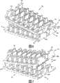
图1是一种接合底架构造的一个实施例的透视图,包括根据本发明原理的第一接合基片的实施例;1 is a perspective view of one embodiment of a jointed chassis construction including an embodiment of a first jointed substrate in accordance with the principles of the present invention;
图2是图1所示接合底架构造的透视图,包括第二接合基片;Figure 2 is a perspective view of the bonded chassis construction shown in Figure 1, including a second bonded substrate;
图3是图1和2所示第一和第二接合基片中的一个的侧面透视图;Figure 3 is a side perspective view of one of the first and second bonded substrates shown in Figures 1 and 2;
图4是图3所示接合基片的相对侧的透视图;Figure 4 is a perspective view of the opposite side of the bonded substrate shown in Figure 3;
图5是图3所示接合基片的侧视图;Fig. 5 is a side view of the bonded substrate shown in Fig. 3;
图6是图2所示第一和第二接合基片的侧面透视图;Figure 6 is a side perspective view of the first and second bonded substrates shown in Figure 2;
图7是图6所示第一和第二接合基片的相对侧的透视图;Figure 7 is a perspective view of opposite sides of the first and second bonded substrates shown in Figure 6;
图8是图6所示第一和第二接合基片的另一个侧面透视图;Figure 8 is another side perspective view of the first and second bonded substrates shown in Figure 6;
图9是图8所示第一和第二接合基片的相对侧的透视图;Figure 9 is a perspective view of opposite sides of the first and second bonded substrates shown in Figure 8;
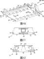
图10是图4所示接合基片的底部透视图;Figure 10 is a bottom perspective view of the bonded substrate shown in Figure 4;
图11是图5所示接合基片的端视图;Figure 11 is an end view of the bonded substrate shown in Figure 5;
图12是图11所示接合基片的相对端视图;Figure 12 is an opposite end view of the bonded substrate shown in Figure 11;
图13是图1所示接合底架构造的透视图,示出了第一接合基片的位置,并且Figure 13 is a perspective view of the bonded chassis configuration shown in Figure 1 showing the position of the first bonded substrate, and
图14是图7所示第一和第二接合基片的透视图,示出为具有接合元件。14 is a perspective view of the first and second bonded substrates shown in FIG. 7, shown with bonding elements.
具体实施方式Detailed ways
现在将详细地参照本发明在附图中示出的各个特征。只要可能,同样的参考标号将在全部附图中用来涉及同样或类似的部件。Reference will now be made in detail to the various features of the invention illustrated in the accompanying drawings. Wherever possible, the same reference numbers will be used throughout the drawings to refer to the same or like parts.
图1和2示出了接合底架构造10的一个实施例,其具有作为根据本发明原理的创造性方面可如何实践的例子的特征。优选的特征中的一个涉及增大接合底架构造的接合元件密度而没有降低存储能力。Figures 1 and 2 illustrate one embodiment of a
如图1和图2所示,接合底架构造10用于容纳接合的光纤线缆12。在接合光纤线缆中,两个光纤线缆由接合元件14连接或接合在一起。所示接合元件14是用来连接带状线缆的多个光纤的圆柱形的多路熔接(mass fusion)接合元件。根据公开的原理,接合底架构造的结构和尺寸能够设计为与其它类型的接合元件一起使用,比如举例来说用于连接单根光纤线缆的多股绞合热收缩接合元件。As shown in FIGS. 1 and 2 , the
本发明的接合底架构造10一般包括基部或底架16和用来保持或维持接合元件14的接合基片构造18。通常,在使用中,提供相当多的松散线缆以允许无需完全更换线缆而对接合元件14进行维护或替换。松散线缆存储在底架16的内部储存区域20中。线缆管理部件22,例如突出部,定位于储存区域20内用来保持和管理松散线缆。The
I.底架I. Chassis
仍然参照图1,接合底架构造10的底架16包括大致平状的底面24。底架的侧面从底面24向上或垂直于底面24延伸。在图示实施例中,底架的侧面包括两个相对的底架侧面26和一个与两个相对的底架侧面26横向的底架侧面28。横向的底架侧面28中心地定位于底架16的第一端30处。第一和第二线缆入孔32、34定位于底架16与底架侧面28靠近的第一端30的相对角部处。第一和第二线缆入孔32、34每个都用作线缆入口和/或线缆出口。底架16的第二端36是开口端。第二开口端36也用作接合底架构造10的线缆入口和/或线缆出口。在使用中,光纤线缆12能够通过底架16的第一开口端36、第一线缆入孔32和第二线缆入孔34中的任意一个进入和离开。为了管理进入和离开底架16的线缆的组织,线缆能够被固定在底架16上特定的进入和离开位置。特别地,在靠近底架16的第一开口端36以及第一和第二线缆入孔32、34处设置孔48。通过孔48构造的系带或其它固定设备(未示出)能够用来将线缆12系紧或固定在特定的进入和离开位置。Still referring to FIG. 1 , the
接合底架构造10的线缆管理部件22(例如突出部)沿着底架16的每个侧面26、28形成。突出部22将线缆维持在底架16的内部储存区域20内。在所示实施例中,槽43形成于底架16的底面24中,与每个突出部22相对,用于制造的目的。A cable management feature 22 , such as a protrusion, that engages the
接合底架构造10还能包括盖(未示出)。底架16包括盖附接结构38,其用来接收盖的配合结构以便将盖紧固至底架。在所示实施例中,盖附接结构38包括形成于底架16的相对侧面26的至少一个中的开口40。在一个可选实施例中,盖附接结构38能够在接合底架16的横向侧面28中形成。The
接合底架构造10的底架16优选地为模塑构造。底架16能够由普通工程材料模塑,包括普通工程聚合物,比如聚对苯二甲酸丁二酯(PBT)、聚碳酸酯(PC)、聚苯醚(polyethylene ether,PPE)以及聚苯乙烯(PS)。The
II.接合基片构造II. Bonding substrate structure
本发明的接合基片构造18优选地包括至少一个具有可层叠结构的第一接合基片18A。层叠结构允许多个接合基片(例如在图2中示出的18A和18B)彼此层叠以增大接合底架构造10的接合元件密度,而没有降低存储能力。图3-5示出了接合底架构造10的接合基片(例如,18A)中的一个。一般地,图2中示出的接合基片18A、18B在构成上是一样的;因此,关于图3-5示出的第一接合基片18A所描述的原理和构造也应用于第二接合基片18B。The bonded
接合基片18A通常包括基部44和多个臂46。基部44具有顶面61(图4)和底面63(图5)。多个臂46从基部44的顶面61向上延伸或突出。臂46的每一个都具有自由端92(图4)以及与基部44一体成形的相反端94。臂46限定了让接合元件14放置并保持于其中的槽或通道52(图5)。如图5所示,每一个通道52彼此平行地延伸。在所示实施例中,接合基片18A包括六个平行通道52。
参照图3和4,接合基片18A的臂46布置成第一和第二排臂62、64。一排54间隔件56定位于第一和第二排臂62、64之间。接合基片18A的通道52每个都部分地由至少一个臂46和一个间隔件54限定。如图5所示,通道52具有由臂46限定的高度H。在所示实施例中,高度H至少为大约.160英寸以适应接收具有类似尺寸直径的接合元件14。Referring to FIGS. 3 and 4 , the arms 46 of the engaging
如图3-5所示,接合基片18A优选地包括用来将接合元件14维持在通道52内的维持结构50。在所示实施例中,维持结构50包括定位于臂46的自由端92处的突出部或头部80。头部80被构造和构造为将接合元件14紧固地扣合在通道52内。在放置于通道52中时,接合元件14靠在基部44的第一和第二侧缘96、98(图3和4)之上。在所示实施例中,侧缘96、98包括像支承接合元件14的棘爪或切口99。As shown in FIGS. 3-5 , the
能够理解到,优选地接合基片18A的臂46是柔性的以提供前述扣合的维持特征。臂46的柔性构造能够由臂的制造材料或尺寸构造中任何一个或两者的选择提供。能至少用来制造接合基片18A的臂46的材料,包括普通工程聚合物,比如举例来说聚对苯二甲酸丁二酯(PBT)、聚碳酸酯(PC)、聚苯醚(PPE)以及聚苯乙烯(PS)。It will be appreciated that preferably the arms 46 engaging the
在使用中,通过将接合元件14向下压到相关臂46的头部80的倾斜面39(图5)之上,接合元件14插入一个通道52中。向下的力使臂46向外弯曲以接受接合元件14。接合元件14由臂46的头部80保持在通道52内。和臂46的柔性构造相比,接合基片18A的间隔件56能够由一种更刚性的构造制成。间隔件56,例如,不包括维持结构(例如50),因此不要求弯曲或者用作扣合的维持件。In use, the
III.安装构造III. Installation structure
返回参考图1,本发明的接合基片18A通常安装至底架16的底面24。接合底架构造10包括在不使用胶粘剂或另外紧固件之下将接合基片18A可分离地固定至底架16的安装构造84。安装构造84包括布置于接合基片18A和底架16的每一个上的互锁的纵向导向件86(图5)、88(图1)。Referring back to FIG. 1 , the bonded
返回参考图3-5,接合基片18A的纵向导向件86包括定位于接合基片18A的第一和第二相反端19、21处的一体成形的唇缘或凸耳90。凸耳90横向向外地延伸超出基部44的端部66、68,并且从基部44的底面63偏移或间隔一段距离。基部44包括在邻近导向件86的每个端部66、68处的倾斜部分45(图5)。在接合基片18A的端部19、21处,在每个导向件86和基部44的倾斜部分45之间设置互锁空间47。Referring back to FIGS. 3-5 , the
现在参照图13,底架16的纵向导向件88包括从底架的底面24向外突出的肋条或轨道89。在所示实施例中,轨道89一体地形成在底架16的底面24上。轨道89具有与接合基片18A提供的互锁空间47相对应的横截面构造。相反横截面构造的轨道89在接合基片18A的互锁空间47内滑动以将接合基片18A固定至底架16的底面24。Referring now to FIG. 13 , the
在将接合基片18A固定至底架16时,接合基片18A以横向A滑动,如图1所示,以使得安装构造84的互锁导向件86、88彼此相啮合。在可选方案,可通过以相反的横向B滑动接合基片18A将接合基片18A固定至底架16。在安装构造84的互锁导向件86、88啮合时,就能防止接合基片18A在与底架的底面24横向的方向上运动。In securing the
现在参照图6-10,接合基片18优选地构造成在不降低接合底架构造10内的存储能力的情况下容纳密度增大的接合元件14(图2)。因此接合基片18A、18B是可层叠的。就是说,接合基片18A、18B构造为在底架16的特定接合基片安装位置42(图13)处彼此层叠。如图13所示,接合基片安装位置42通常限定在安装构造84的轨道89之间。Referring now to FIGS. 6-10 , the
参照图6和7,接合基片18A、18B的每一个包括将接合基片相对彼此可分离地固定的扣合层叠构造60。在所示实施例中,接合基片18A、18B彼此层叠。虽然所涉及的是彼此层叠,但是可以理解,接合基片18A、18B不限于竖直层叠的构造。而是,词语“彼此层叠”用于所示实施例的解释性目的。例如,接合基片可以根据底架的朝向以前后构造来层叠。Referring to Figures 6 and 7, each of the bonded
优选地,接合基片18A、18B的层叠构造60构造为与接合底架构造10的安装构造84可互换地起作用。也就是,层叠构造60包括安装构造84的互锁导向件86以便层叠构造60和安装构造84二者用来将接合基片安装至另一个接合基片,以及将接合基片安装至底架16。通过这样,接合基片18A、18B是可互换的并且不需要专门用作可层叠基片或底架安装基片。Preferably, the stacked
仍旧参照图6和7,接合基片18A、18B的每一个的层叠构造60还包括定位在接合基片18A、18B的第一端19处的第一和第二锁闭元件70、72以及定位在接合基片的第二相反端21处的第三锁闭元件74。每一个接合基片的锁闭元件70、72、74构造为啮合或锁闭入另一个接合基片的互锁空间47内。Still referring to FIGS. 6 and 7 , the stacked
现在参照图10,第一、第二和第三槽71、73、75为了制造的目的而形成于基部44的端部66、68。槽71、73、75限定了互锁空间47的与锁闭元件70、72、74的构造相对应的段。层叠接合基片18A、18B从而以交替的方式层叠以适应槽和锁闭元件的构造。也就是,第一和第二接合基片18A、18B的相反端(例如19和21)构造为彼此互锁。在可选方案中,基部44的端部66、68能够制造为没有槽,从而允许第一和第二接合基片的相同端部(例如19和19)互锁。Referring now to FIG. 10 , first, second and
如图6和7所示,为了以层叠关系装配接合基片18A、18B,底部接合基片18A的第一端19处的第一和第二锁闭元件70、72定位在设置于顶部接合基片18B的第二端21处的互锁空间47内(图10和12)。现在参照图8和9,顶部接合基片18B然后回转以使得底部接合基片18A的第二端21处的第三锁闭元件74扣合入设置在顶部接合基片18B的第一端19处的互锁空间47(图11)。在可选方案中,底部接合基片18A的第三锁闭元件74最初能够啮合在设置于顶部接合基片18B上的锁闭空间内,并且然后第一和第二锁闭元件在顶部接合基片18B的另一端处扣合入相关的锁闭空间47。As shown in FIGS. 6 and 7 , to assemble the
能够理解到,优选地,层叠构造60的第三锁闭元件74以及第一和第二锁闭元件70、72中的至少一个是柔性的以提供所述扣合的维持特征。锁闭元件的柔性构造能够通过锁闭元件的制造材料和尺寸构造中任意一个或两个的选择来提供。It will be appreciated that, preferably, the
再参照图10,基部44的底面63至少包括第一凹槽82。凹槽82的尺寸设计为接收布置于接合基片18A、18B的一个间隔件56的顶部上的导向件58(图3)。在所示实施例中,两个导向件58(图3)和凹槽82设置于接合基片18A、18B上。导向件58和凹槽82构造来协助顶部接合基片18B相对于底部接合基片18A的正确定位或对准。导向件58和凹槽82还协助在以层叠关系固定时防止顶部接合基片18B相对于底部接合基片18A的横向运动。Referring again to FIG. 10 , the bottom surface 63 of the
在使用中,为了接合底架构造10的装配,第一接合基片18A附接至底架16的底面24。具体的,第一接合基片18A以横向A滑动(图1)以使得接合基片18A和底架16的互锁导向件86、88相啮合。柔性固定突出部76、78(图13)提供来防止接合基片18A意外地横向运动超过基片安装位置42。In use, for the assembly of the
在第一接合基片18A被固定至底架16时,接合元件14能够放置入接合基片的通道52内。在将期望数目的接合元件14构造在接合基片18A的通道52内之后,第二接合基片18B能够层叠在第一接合基片18A之上。第二接合基片18B以前面所述的方式附接至第一接合基片18A。另外的接合元件14然后能够放置和固定在第二接合基片18B的通道52内。在可选方案中,接合元件14能够在将基片固定至底架16或者另一基片之前放置在接合基片18A、18B的通道52内。如图14所示,总共十二个接合元件14能够由所示接合基片构造18所保持。When the
现在参照图14,接合基片18A、18B的每一个包括一个用于从层叠的接合基片中将顶部接合基片(例如,18B)分离的释放突出部100。释放突出部100定位为邻近第三锁闭元件74的顶部边缘102。在一个向下或向外的拉力F施加于下面接合基片18A的突出部100时,下面接合基片18A的锁闭元件74向外弯曲从而从顶部接合基片18B的互锁空间47中脱离。通过将顶部接合基片18B向上枢转并使该接合基片从底部接合基片18A的第一和第二锁闭元件70、72中脱离,顶部接合基片18B就能从层叠中移除。通过将柔性固定突出部76、78中的一个压下为与底架16的底面24平齐,并且横向地滑动基片18A以使得接合基片和底架的互锁导向件86、88脱离,就能将底部接合基片18A从底架16移除。Referring now to FIG. 14, each of the bonded
所公开的接合底架构造10的总体构造和构造通过提供一种易于使用并增大接合元件密度的接合基片构造增强了线缆管理。上述说明提供了本发明的完全描述。由于发明的很多实施例能够在不脱离本发明精神和范围之下做出,因此发明的某些方面存在于下面所附的权利要求中。The overall configuration and construction of the disclosed
Claims (22)
Translated fromChineseApplications Claiming Priority (3)
| Application Number | Priority Date | Filing Date | Title |
|---|---|---|---|
| US11/212,470US7310471B2 (en) | 2005-08-25 | 2005-08-25 | Stackable splice chip device |
| US11/212,470 | 2005-08-25 | ||
| PCT/US2006/032859WO2007024912A1 (en) | 2005-08-25 | 2006-08-22 | Stackable splice chip device |
Publications (2)
| Publication Number | Publication Date |
|---|---|
| CN101243347A CN101243347A (en) | 2008-08-13 |
| CN101243347Btrue CN101243347B (en) | 2011-05-18 |
Family
ID=37433729
Family Applications (1)
| Application Number | Title | Priority Date | Filing Date |
|---|---|---|---|
| CN2006800296856AExpired - Fee RelatedCN101243347B (en) | 2005-08-25 | 2006-08-22 | Stackable splice chip device |
Country Status (10)
| Country | Link |
|---|---|
| US (3) | US7310471B2 (en) |
| EP (1) | EP1929348B1 (en) |
| JP (1) | JP2009506362A (en) |
| KR (1) | KR20080039489A (en) |
| CN (1) | CN101243347B (en) |
| AT (1) | ATE528677T1 (en) |
| AU (1) | AU2006283165B2 (en) |
| BR (1) | BRPI0615366A2 (en) |
| ES (1) | ES2370263T3 (en) |
| WO (1) | WO2007024912A1 (en) |
Families Citing this family (112)
| Publication number | Priority date | Publication date | Assignee | Title |
|---|---|---|---|---|
| US7310471B2 (en)* | 2005-08-25 | 2007-12-18 | Adc Telecommunications, Inc. | Stackable splice chip device |
| US7272291B2 (en)* | 2005-08-25 | 2007-09-18 | Adc Telecommunications, Inc. | Splice chip device |
| DE102007009223B4 (en)* | 2007-02-26 | 2011-03-17 | Adc Gmbh | Strain relief for cables |
| US7822310B2 (en) | 2007-02-28 | 2010-10-26 | Corning Cable Systems Llc | Fiber optic splice trays |
| US8798427B2 (en) | 2007-09-05 | 2014-08-05 | Corning Cable Systems Llc | Fiber optic terminal assembly |
| WO2009048795A1 (en)* | 2007-10-09 | 2009-04-16 | 3M Innovative Properties Company | Splice holder with ejector |
| DE202008002812U1 (en)* | 2008-02-28 | 2008-04-24 | CCS Technology, Inc., Wilmington | Holding device for splice protection devices with splices of optical waveguides received in the splice protection devices |
| US7889961B2 (en) | 2008-03-27 | 2011-02-15 | Corning Cable Systems Llc | Compact, high-density adapter module, housing assembly and frame assembly for optical fiber telecommunications |
| WO2009131770A2 (en)* | 2008-04-21 | 2009-10-29 | Afl Telecommunications Llc | Fiber optic splice tray |
| EP2277071A2 (en) | 2008-04-21 | 2011-01-26 | ADC Telecommunications, Inc. | Fiber optic splice tray |
| US11294136B2 (en) | 2008-08-29 | 2022-04-05 | Corning Optical Communications LLC | High density and bandwidth fiber optic apparatuses and related equipment and methods |
| US8452148B2 (en) | 2008-08-29 | 2013-05-28 | Corning Cable Systems Llc | Independently translatable modules and fiber optic equipment trays in fiber optic equipment |
| US8290333B2 (en) | 2008-08-29 | 2012-10-16 | Corning Cable Systems Llc | Fiber optic cable assemblies with furcation bodies having features for manufacturing and methods of making the same |
| US8135257B2 (en)* | 2008-08-29 | 2012-03-13 | Corning Cable Systems Llc | Structures for managing and mounting cable assemblies |
| US8301004B2 (en)* | 2008-08-29 | 2012-10-30 | Corning Cable Systems Llc | Fiber optic cable assemblies employing a furcation body having anti-rotation feature |
| US8086084B2 (en)* | 2008-09-09 | 2011-12-27 | Adc Telecommunications, Inc. | Fiber optic splice tray |
| CN102209921B (en) | 2008-10-09 | 2015-11-25 | 康宁光缆系统有限公司 | There is the fibre-optic terminus supported from the adapter panel of the input and output optical fiber of optical splitters |
| US8879882B2 (en) | 2008-10-27 | 2014-11-04 | Corning Cable Systems Llc | Variably configurable and modular local convergence point |
| US8165442B2 (en)* | 2008-11-06 | 2012-04-24 | Ofs Fitel, Llc | System for securing fiber optic devices in management trays |
| CN102282495B (en)* | 2009-01-15 | 2015-04-22 | Adc电信公司 | Fiber optic module, chassis and adapter |
| EP2221932B1 (en) | 2009-02-24 | 2011-11-16 | CCS Technology Inc. | Holding device for a cable or an assembly for use with a cable |
| EP2237091A1 (en) | 2009-03-31 | 2010-10-06 | Corning Cable Systems LLC | Removably mountable fiber optic terminal |
| US8699838B2 (en) | 2009-05-14 | 2014-04-15 | Ccs Technology, Inc. | Fiber optic furcation module |
| US9075216B2 (en) | 2009-05-21 | 2015-07-07 | Corning Cable Systems Llc | Fiber optic housings configured to accommodate fiber optic modules/cassettes and fiber optic panels, and related components and methods |
| US8538226B2 (en) | 2009-05-21 | 2013-09-17 | Corning Cable Systems Llc | Fiber optic equipment guides and rails configured with stopping position(s), and related equipment and methods |
| EP2443497B1 (en) | 2009-06-19 | 2020-03-04 | Corning Cable Systems LLC | High density and bandwidth fiber optic apparatus |
| US8712206B2 (en) | 2009-06-19 | 2014-04-29 | Corning Cable Systems Llc | High-density fiber optic modules and module housings and related equipment |
| WO2010148325A1 (en) | 2009-06-19 | 2010-12-23 | Corning Cable Systems Llc | High fiber optic cable packing density apparatus |
| US7945136B2 (en)* | 2009-06-19 | 2011-05-17 | Corning Cable Systems Llc | Mounting of fiber optic cable assemblies within fiber optic shelf assemblies |
| US8467651B2 (en) | 2009-09-30 | 2013-06-18 | Ccs Technology Inc. | Fiber optic terminals configured to dispose a fiber optic connection panel(s) within an optical fiber perimeter and related methods |
| US8625950B2 (en) | 2009-12-18 | 2014-01-07 | Corning Cable Systems Llc | Rotary locking apparatus for fiber optic equipment trays and related methods |
| EP2354824A1 (en)* | 2010-01-29 | 2011-08-10 | CCS Technology Inc. | Hybrid connector |
| US8992099B2 (en) | 2010-02-04 | 2015-03-31 | Corning Cable Systems Llc | Optical interface cards, assemblies, and related methods, suited for installation and use in antenna system equipment |
| AU2011224314A1 (en) | 2010-03-10 | 2012-09-06 | Corning Cable Systems Llc | Fiber optic pigtail assembly allowing single and mass splicing |
| US9547144B2 (en) | 2010-03-16 | 2017-01-17 | Corning Optical Communications LLC | Fiber optic distribution network for multiple dwelling units |
| US8913866B2 (en) | 2010-03-26 | 2014-12-16 | Corning Cable Systems Llc | Movable adapter panel |
| US8792767B2 (en) | 2010-04-16 | 2014-07-29 | Ccs Technology, Inc. | Distribution device |
| CA2796221C (en) | 2010-04-16 | 2018-02-13 | Ccs Technology, Inc. | Sealing and strain relief device for data cables |
| EP2381284B1 (en) | 2010-04-23 | 2014-12-31 | CCS Technology Inc. | Under floor fiber optic distribution device |
| US8879881B2 (en) | 2010-04-30 | 2014-11-04 | Corning Cable Systems Llc | Rotatable routing guide and assembly |
| US9632270B2 (en) | 2010-04-30 | 2017-04-25 | Corning Optical Communications LLC | Fiber optic housings configured for tool-less assembly, and related components and methods |
| US8385711B2 (en) | 2010-04-30 | 2013-02-26 | Corning Cable Systems Llc | Multi-configurable splice holder |
| US8705926B2 (en) | 2010-04-30 | 2014-04-22 | Corning Optical Communications LLC | Fiber optic housings having a removable top, and related components and methods |
| US9075217B2 (en) | 2010-04-30 | 2015-07-07 | Corning Cable Systems Llc | Apparatuses and related components and methods for expanding capacity of fiber optic housings |
| US8660397B2 (en) | 2010-04-30 | 2014-02-25 | Corning Cable Systems Llc | Multi-layer module |
| US9720195B2 (en) | 2010-04-30 | 2017-08-01 | Corning Optical Communications LLC | Apparatuses and related components and methods for attachment and release of fiber optic housings to and from an equipment rack |
| US9519118B2 (en) | 2010-04-30 | 2016-12-13 | Corning Optical Communications LLC | Removable fiber management sections for fiber optic housings, and related components and methods |
| US8254742B2 (en)* | 2010-05-11 | 2012-08-28 | Commscope, Inc. Of North Carolina | Splice holder |
| US8718436B2 (en) | 2010-08-30 | 2014-05-06 | Corning Cable Systems Llc | Methods, apparatuses for providing secure fiber optic connections |
| AU2015224528B2 (en)* | 2010-10-19 | 2017-09-14 | Corning Cable Systems Llc | Local convergence point for multiple dwelling unit fiber optic distribution network |
| WO2012054454A2 (en)* | 2010-10-19 | 2012-04-26 | Corning Cable Systems Llc | Transition box for multiple dwelling unit fiber optic distribution network |
| US9279951B2 (en) | 2010-10-27 | 2016-03-08 | Corning Cable Systems Llc | Fiber optic module for limited space applications having a partially sealed module sub-assembly |
| US8662760B2 (en) | 2010-10-29 | 2014-03-04 | Corning Cable Systems Llc | Fiber optic connector employing optical fiber guide member |
| US9116324B2 (en) | 2010-10-29 | 2015-08-25 | Corning Cable Systems Llc | Stacked fiber optic modules and fiber optic equipment configured to support stacked fiber optic modules |
| CA2819235C (en) | 2010-11-30 | 2018-01-16 | Corning Cable Systems Llc | Fiber device holder and strain relief device |
| WO2012106510A2 (en) | 2011-02-02 | 2012-08-09 | Corning Cable Systems Llc | Dense fiber optic connector assemblies and related connectors and cables suitable for establishing optical connections for optical backplanes in equipment racks |
| US9052468B2 (en)* | 2011-03-04 | 2015-06-09 | Corning Cable Systems Llc | Fiber optic adapter mount |
| US9182563B2 (en) | 2011-03-31 | 2015-11-10 | Adc Telecommunications, Inc. | Adapter plate for fiber optic module |
| US9008485B2 (en) | 2011-05-09 | 2015-04-14 | Corning Cable Systems Llc | Attachment mechanisms employed to attach a rear housing section to a fiber optic housing, and related assemblies and methods |
| AU2012275598A1 (en) | 2011-06-30 | 2014-01-16 | Corning Optical Communications LLC | Fiber optic equipment assemblies employing non-U-width-sized housings and related methods |
| US8792753B2 (en)* | 2011-06-30 | 2014-07-29 | General Electric Company | Method and system for a fiber optic sensor |
| US9110266B2 (en) | 2011-07-29 | 2015-08-18 | Corning Cable Systems Llc | Fiber optic cables seal and/or strain relief members, and related assemblies and methods |
| JP5325967B2 (en)* | 2011-11-28 | 2013-10-23 | 株式会社フジクラ | Optical fiber connection unit |
| CN103765266A (en) | 2011-08-09 | 2014-04-30 | 株式会社藤仓 | Mechanical splicing unit, connecting tool for mechanical splicing, and construction method for optical fiber splicing |
| US8953924B2 (en) | 2011-09-02 | 2015-02-10 | Corning Cable Systems Llc | Removable strain relief brackets for securing fiber optic cables and/or optical fibers to fiber optic equipment, and related assemblies and methods |
| WO2013033890A1 (en) | 2011-09-06 | 2013-03-14 | Adc Telecommunications, Inc. | Adapter for fiber optic module |
| US8950712B2 (en)* | 2011-10-14 | 2015-02-10 | Heyco, Inc. | Cable holder |
| US8559784B2 (en)* | 2011-10-26 | 2013-10-15 | All Systems Broadband, Inc. | Modular assembly for supporting fiber optic splices |
| US9207422B2 (en)* | 2011-10-26 | 2015-12-08 | All Systems Broadband, Inc. | Holders for optical fiber splice sleeves and passive optical components |
| US9038832B2 (en) | 2011-11-30 | 2015-05-26 | Corning Cable Systems Llc | Adapter panel support assembly |
| US9219546B2 (en) | 2011-12-12 | 2015-12-22 | Corning Optical Communications LLC | Extremely high frequency (EHF) distributed antenna systems, and related components and methods |
| US8842962B2 (en) | 2012-01-27 | 2014-09-23 | Corning Cable Systems Llc | Fiber optic cable strain relief device and method |
| US10110307B2 (en) | 2012-03-02 | 2018-10-23 | Corning Optical Communications LLC | Optical network units (ONUs) for high bandwidth connectivity, and related components and methods |
| WO2013177413A1 (en) | 2012-05-25 | 2013-11-28 | Adc Telecommunications, Inc. | Splice chips for optical fiber splice cassettes |
| US9004778B2 (en) | 2012-06-29 | 2015-04-14 | Corning Cable Systems Llc | Indexable optical fiber connectors and optical fiber connector arrays |
| US9250409B2 (en) | 2012-07-02 | 2016-02-02 | Corning Cable Systems Llc | Fiber-optic-module trays and drawers for fiber-optic equipment |
| US9049500B2 (en) | 2012-08-31 | 2015-06-02 | Corning Cable Systems Llc | Fiber optic terminals, systems, and methods for network service management |
| US9042702B2 (en) | 2012-09-18 | 2015-05-26 | Corning Cable Systems Llc | Platforms and systems for fiber optic cable attachment |
| US8909019B2 (en) | 2012-10-11 | 2014-12-09 | Ccs Technology, Inc. | System comprising a plurality of distribution devices and distribution device |
| ES2551077T3 (en) | 2012-10-26 | 2015-11-16 | Ccs Technology, Inc. | Fiber optic management unit and fiber optic distribution device |
| EP2725396B1 (en) | 2012-10-26 | 2016-09-14 | CCS Technology, Inc. | Strain relief device for cables and fiber optic distribution device |
| WO2014071021A1 (en)* | 2012-10-31 | 2014-05-08 | Adc Telecommunications, Inc. | Anchoring cables to rack with cable clamp arrangements |
| CA2931089C (en)* | 2012-12-07 | 2021-11-02 | Corning Optical Communications LLC | Fiber optic modules with splice holder and fiber management features |
| US8985862B2 (en) | 2013-02-28 | 2015-03-24 | Corning Cable Systems Llc | High-density multi-fiber adapter housings |
| US9606315B2 (en)* | 2013-03-15 | 2017-03-28 | All Systems Broadband, Inc. | Optical fiber ribbon storage |
| US9488793B2 (en) | 2013-09-10 | 2016-11-08 | Corning Optical Communications LLC | Combined optical fiber and power cable |
| US10061089B2 (en)* | 2013-09-20 | 2018-08-28 | Adva Optical Networking Se | Fiber optic component holding device for fibers in side-by-side contact |
| EP2960698B1 (en)* | 2014-06-27 | 2017-08-09 | CCS Technology, Inc. | Splice holder for splice protectors protecting splices between optical fibers provided by single fiber splicing |
| US9494760B2 (en) | 2015-02-17 | 2016-11-15 | 3M Innovative Properties Company | Highly configurable fiber-optic interconnection tray |
| USD781788S1 (en)* | 2015-03-31 | 2017-03-21 | Optical Cable Corporation | Splice tray cabinet |
| WO2017124018A1 (en) | 2016-01-14 | 2017-07-20 | Communications Systems, Inc. | Stackable splitters |
| KR200485520Y1 (en)* | 2016-02-22 | 2018-01-19 | 주식회사 에이.제이.월드 | Tray for fiber optic splice closure and fiber optic splice closure comprising the same |
| US10295771B2 (en) | 2016-05-03 | 2019-05-21 | Corning Optical Communications LLC | Telecommunications terminal with removable modules |
| MX387950B (en)* | 2016-10-25 | 2025-03-19 | Commscope Technologies Llc | Fiber clip and method of use |
| EP3698192A4 (en)* | 2017-10-17 | 2021-09-22 | Corning Research And Development Corporation | HOUSING FOR SPLICE OF OPTICAL FIBERS |
| CN107976754A (en)* | 2017-12-14 | 2018-05-01 | 江苏亨通光电股份有限公司 | Lineation box device built in a kind of optical fiber case |
| WO2019209643A1 (en)* | 2018-04-23 | 2019-10-31 | Commscope Technologies Llc | Mechanical connection interface for a telecommunications component |
| US10852498B2 (en)* | 2018-05-24 | 2020-12-01 | Clearfield, Inc. | Optical fiber distribution systems and components |
| WO2019231597A1 (en)* | 2018-05-30 | 2019-12-05 | Corning Research & Development Corporation | Modular optical fiber splice tray system |
| EP3745177A1 (en)* | 2019-05-29 | 2020-12-02 | CommScope Technologies LLC | Fiber optic holder tray adapter; assembly; and method |
| US10845561B1 (en) | 2019-06-28 | 2020-11-24 | Afl Telecommunications Llc | Fiber optic cassettes and splice modules |
| US20220299726A1 (en)* | 2019-08-15 | 2022-09-22 | Commscope Technologies Llc | Dual-sided splice cassette |
| WO2021195371A1 (en)* | 2020-03-27 | 2021-09-30 | All Systems Broadband, Inc. | Stackable fiber optic splice holder |
| IT202000007045A1 (en) | 2020-04-02 | 2021-10-02 | Prysmian Spa | Tray for fiber optic splices |
| US11947178B2 (en) | 2020-09-17 | 2024-04-02 | Panduit Corp. | Optical distribution and splice frame including cassettes |
| US11971598B2 (en) | 2021-02-18 | 2024-04-30 | Commscope Technologies Llc | Tray arrangements for cassettes |
| US11740421B2 (en)* | 2021-02-18 | 2023-08-29 | Commscope Technologies Llc | Communications panel system |
| US11927808B2 (en) | 2021-04-16 | 2024-03-12 | Commscope Technologies Llc | Holder for an optical component |
| US12105339B2 (en)* | 2021-06-04 | 2024-10-01 | Sumitomo Electric Industries, Ltd. | Wiring module, frame body for wiring module, and forming method for forming wiring module |
| CA3233329A1 (en)* | 2021-09-27 | 2023-03-30 | Amphenol Network Solutions, Inc. | Stackable fiber optic splice holder with space efficient splice holder retention |
| US12259590B2 (en)* | 2021-11-29 | 2025-03-25 | Corning Research & Development Corporation | Fiber-optic apparatus |
| EP4286910A1 (en)* | 2022-06-01 | 2023-12-06 | Corning Research & Development Corporation | Removable optical organizer |
Family Cites Families (57)
| Publication number | Priority date | Publication date | Assignee | Title |
|---|---|---|---|---|
| US4840449A (en) | 1988-01-27 | 1989-06-20 | American Telephone And Telegraph Company, At&T Bell Laboratories | Optical fiber splice organizer |
| GB8805017D0 (en) | 1988-03-02 | 1988-03-30 | British Telecomm | Splice tray |
| US4900123A (en) | 1988-08-29 | 1990-02-13 | Gte Products Corporation | 1550 nm fiber distribution panel |
| GB2237121B (en) | 1989-10-10 | 1993-07-21 | Bowthorpe Hellermann Ltd | Optical fibre splice storage enclosure |
| US5074635A (en) | 1990-05-21 | 1991-12-24 | Minnesota Mining And Manufacturing Company | Splice tray and method |
| US5185845A (en)* | 1990-12-13 | 1993-02-09 | At&T Bell Laboratories | Optical fiber closure having enhanced storage capability |
| US5119459A (en) | 1991-02-15 | 1992-06-02 | Porta Systems Corp. | Optical fiber storage and distribution cabinet |
| US5189725A (en)* | 1992-01-28 | 1993-02-23 | At&T Bell Laboratories | Optical fiber closure |
| US5323480A (en) | 1992-11-25 | 1994-06-21 | Raychem Corporation | Fiber optic splice closure |
| DE4302837A1 (en) | 1993-01-28 | 1994-08-18 | Krone Ag | Housing for passive optical components |
| US5363467A (en) | 1993-05-28 | 1994-11-08 | Minnesota Mining And Manufacturing Company | Compact fiber optic housing |
| US5548678A (en) | 1993-09-10 | 1996-08-20 | British Telecommunications Public Limited Company | Optical fibre management system |
| US5490229A (en) | 1993-12-08 | 1996-02-06 | At&T Ipm Corp. | Slidably mounted optical fiber distribution tray |
| DE4415218C1 (en) | 1994-04-26 | 1995-10-19 | Krone Ag | Housing for optical components |
| US5519804A (en) | 1994-06-22 | 1996-05-21 | At&T Corp. | Universal splice tray |
| WO1996010203A1 (en) | 1994-09-28 | 1996-04-04 | Telephone Cables Limited | A splice tray |
| US5450518A (en) | 1994-10-13 | 1995-09-12 | At&T Corp. | Optical fiber cable splice closure |
| US5689605A (en) | 1995-02-09 | 1997-11-18 | Lucent Technologies Inc. | Splice holder assembly for an optical fiber cable splice closure |
| US5590234A (en) | 1995-03-31 | 1996-12-31 | Minnesota Mining And Manufacturing Company | Fiber optic splice organizers |
| NZ303594A (en) | 1995-03-31 | 1999-01-28 | Minnesota Mining & Mfg | Optical fibre splice tray arrangement |
| US5553183A (en) | 1995-04-03 | 1996-09-03 | Antec Corp. | Apparatus for and methods of splitting fiber optic signals |
| FR2734651B1 (en) | 1995-05-24 | 1997-06-20 | Alcatel Cable Interface | FIBER OPTIC CONNECTION BOX |
| US5577151A (en) | 1995-08-15 | 1996-11-19 | The Whitaker Corporation | Optical fiber splice tray and cover |
| US5835657A (en) | 1995-12-08 | 1998-11-10 | Psi Telecommunications, Inc. | Fiber optic splice tray |
| US5647045A (en) | 1996-02-23 | 1997-07-08 | Leviton Manufacturing Co., Inc. | Multi-media connection housing |
| DE19611770C2 (en) | 1996-03-14 | 1998-04-09 | Krone Ag | Manageable splice cassette |
| KR100242412B1 (en)* | 1996-10-25 | 2000-03-02 | 윤종용 | Packaging box for fixing optical element of optical fiber amplifier |
| US5825962A (en) | 1996-12-31 | 1998-10-20 | Siecor Corporation | Optical fiber splice housing |
| US5896486A (en) | 1997-05-01 | 1999-04-20 | Lucent Technologies Inc. | Mass splice tray for optical fibers |
| KR100261762B1 (en) | 1997-12-02 | 2000-07-15 | 이계철 | Optical ribbon fiber splice tray |
| US6009225A (en) | 1998-05-26 | 1999-12-28 | Ray; Craig D. | Fiber optic drop splice closure and related methods |
| US6215938B1 (en) | 1998-09-21 | 2001-04-10 | Adc Telecommunications, Inc. | Fiber optic cabinet and tray |
| US6353697B1 (en)* | 1999-07-30 | 2002-03-05 | Lucent Technologies, Inc. | Modular layered splice holder |
| US6285815B1 (en) | 1999-09-07 | 2001-09-04 | Lucent Technologies Inc. | High density fusion splice holder |
| US6249636B1 (en) | 1999-09-07 | 2001-06-19 | Lucent Technologies, Inc. | High density fusion splice holder |
| US6259851B1 (en) | 1999-09-17 | 2001-07-10 | Lucent Technologies Inc. | High density fiber splice holder |
| US6456772B1 (en) | 1999-09-21 | 2002-09-24 | Avaya Technology Corp. | System for removable attachment of two objects |
| US6226436B1 (en) | 1999-11-18 | 2001-05-01 | Lucent Technologies, Inc. | Fiber optical pedestal |
| US6427045B1 (en) | 2000-03-08 | 2002-07-30 | Marconi Communications, Inc. | Splice tray for use in splicing fiber optic cables and housing therefor |
| US6687450B1 (en) | 2000-05-15 | 2004-02-03 | Tyco Electronics Raychem Nv | Break-out device |
| GB2367379B (en) | 2000-09-27 | 2004-08-25 | Krone Gmbh | Opitcal fibre connection housing |
| GB2367378B (en) | 2000-09-27 | 2004-08-25 | Krone Gmbh | Patch panel |
| US6504989B1 (en) | 2000-10-23 | 2003-01-07 | Onetta, Inc. | Optical equipment and methods for manufacturing optical communications equipment for networks |
| US6845207B2 (en) | 2001-02-12 | 2005-01-18 | Fiber Optic Network Solutions Corp. | Optical fiber enclosure system |
| US20020118944A1 (en) | 2001-02-28 | 2002-08-29 | Corning Cable Systems Llc | Optical fiber storage reel |
| US6512876B2 (en) | 2001-04-25 | 2003-01-28 | Lucent Technologies Inc. | Fiber splice tray |
| US6944387B2 (en) | 2001-04-30 | 2005-09-13 | Telect, Inc. | Fiber optic connector tray system |
| US6580866B2 (en) | 2001-05-16 | 2003-06-17 | Lucent Technologies Inc. | Fiber splice holder with protected slack storage feature |
| US6567601B2 (en) | 2001-06-19 | 2003-05-20 | Lucent Technologies Inc. | Fiber-optic cable routing and management system and components |
| US6744962B2 (en) | 2001-10-25 | 2004-06-01 | Uniseal, Inc. | Fiberoptic splice closure |
| US6701056B2 (en)* | 2002-01-02 | 2004-03-02 | Wavesplitter Technologies, Inc. | Modular, variably configurable retainer assembly for optical components |
| US6798966B2 (en) | 2002-11-01 | 2004-09-28 | Hon Hai Precision Ind. Co., Ltd | Dense wavelength division multiplexer module |
| US6801704B1 (en) | 2003-05-30 | 2004-10-05 | Lucent Technologies Inc. | Fiber optics splice holder |
| US6915059B2 (en) | 2003-05-30 | 2005-07-05 | Lucent Technologies Inc. | Stackable optical fiber splice tray and mounting shelves |
| US7272291B2 (en)* | 2005-08-25 | 2007-09-18 | Adc Telecommunications, Inc. | Splice chip device |
| US7310471B2 (en)* | 2005-08-25 | 2007-12-18 | Adc Telecommunications, Inc. | Stackable splice chip device |
| EP1932037B1 (en)* | 2005-10-05 | 2013-06-19 | Tyco Electronics Raychem BVBA | Optical fibre connection devices |
- 2005
- 2005-08-25USUS11/212,470patent/US7310471B2/ennot_activeExpired - Fee Related
- 2006
- 2006-08-22JPJP2008528092Apatent/JP2009506362A/enactivePending
- 2006-08-22CNCN2006800296856Apatent/CN101243347B/ennot_activeExpired - Fee Related
- 2006-08-22AUAU2006283165Apatent/AU2006283165B2/ennot_activeCeased
- 2006-08-22BRBRPI0615366-6Apatent/BRPI0615366A2/ennot_activeApplication Discontinuation
- 2006-08-22KRKR1020087006058Apatent/KR20080039489A/ennot_activeCeased
- 2006-08-22EPEP06802138Apatent/EP1929348B1/ennot_activeNot-in-force
- 2006-08-22WOPCT/US2006/032859patent/WO2007024912A1/enactiveApplication Filing
- 2006-08-22ESES06802138Tpatent/ES2370263T3/enactiveActive
- 2006-08-22ATAT06802138Tpatent/ATE528677T1/ennot_activeIP Right Cessation
- 2007
- 2007-12-14USUS12/002,327patent/US7421182B2/ennot_activeExpired - Fee Related
- 2008
- 2008-08-29USUS12/231,313patent/US7764858B2/ennot_activeExpired - Lifetime
Also Published As
| Publication number | Publication date |
|---|---|
| JP2009506362A (en) | 2009-02-12 |
| US20070047891A1 (en) | 2007-03-01 |
| ES2370263T3 (en) | 2011-12-14 |
| BRPI0615366A2 (en) | 2011-05-17 |
| US7310471B2 (en) | 2007-12-18 |
| ATE528677T1 (en) | 2011-10-15 |
| EP1929348A1 (en) | 2008-06-11 |
| EP1929348B1 (en) | 2011-10-12 |
| CN101243347A (en) | 2008-08-13 |
| AU2006283165B2 (en) | 2011-09-01 |
| WO2007024912A1 (en) | 2007-03-01 |
| US20080181569A1 (en) | 2008-07-31 |
| KR20080039489A (en) | 2008-05-07 |
| US7421182B2 (en) | 2008-09-02 |
| US20090074371A1 (en) | 2009-03-19 |
| AU2006283165A1 (en) | 2007-03-01 |
| US7764858B2 (en) | 2010-07-27 |
Similar Documents
| Publication | Publication Date | Title |
|---|---|---|
| CN101243347B (en) | Stackable splice chip device | |
| US7463810B2 (en) | Splice chip device | |
| KR100620676B1 (en) | Fiber optic assembly | |
| CN101283494B (en) | Cable trough system | |
| US9753238B2 (en) | Adapter plate for fiber optic module | |
| RU2560110C2 (en) | Modular mounting system for fibre-optic cassettes | |
| CN102859412A (en) | Stackable shelves for a fiber optic housing, and related components and methods | |
| CN104137366A (en) | Telecommunications enclosure with splice tray assembly | |
| US9244243B2 (en) | Optical fiber fan-out device for a furcation tube assembly | |
| US8958679B2 (en) | Fibre-optic telecommunications module | |
| CN102272650A (en) | Fiber Optic Adapter Plates and Cassettes | |
| CN105705976A (en) | Telecommunications chassis | |
| US6917746B2 (en) | Apparatus and method for creating a fiber optic circuit | |
| CN102870025A (en) | Fiber optic housings with removable panel clips | |
| CN100371756C (en) | Array of cassettes for splicing optical fibers | |
| CN118534597A (en) | Adapter panel for outdoor fiber distribution closure and related assemblies |
Legal Events
| Date | Code | Title | Description |
|---|---|---|---|
| C06 | Publication | ||
| PB01 | Publication | ||
| C10 | Entry into substantive examination | ||
| SE01 | Entry into force of request for substantive examination | ||
| C14 | Grant of patent or utility model | ||
| GR01 | Patent grant | ||
| C17 | Cessation of patent right | ||
| CF01 | Termination of patent right due to non-payment of annual fee | Granted publication date:20110518 Termination date:20120822 |