CN101234045A - Parallel multi-freedom prosthetic exoskeleton ankle joint - Google Patents
Parallel multi-freedom prosthetic exoskeleton ankle jointDownload PDFInfo
- Publication number
- CN101234045A CN101234045ACNA2008100340027ACN200810034002ACN101234045ACN 101234045 ACN101234045 ACN 101234045ACN A2008100340027 ACNA2008100340027 ACN A2008100340027ACN 200810034002 ACN200810034002 ACN 200810034002ACN 101234045 ACN101234045 ACN 101234045A
- Authority
- CN
- China
- Prior art keywords
- guide rod
- chain guide
- branch chain
- active branch
- seat
- Prior art date
- Legal status (The legal status is an assumption and is not a legal conclusion. Google has not performed a legal analysis and makes no representation as to the accuracy of the status listed.)
- Granted
Links
Images

Landscapes
- Manipulator (AREA)
Abstract
Translated fromChinese
Description
Translated fromChinese技术领域technical field
本发明涉及的是一种康复工程技术领域的装置,具体是一种并联式多自由度假肢外骨骼踝关节。The invention relates to a device in the technical field of rehabilitation engineering, in particular to a parallel multi-free artificial limb exoskeleton ankle joint.
背景技术Background technique
近年来,由于交通事故、体育事故、工伤、战争等意外事故和人口老龄化造成的肢体残疾人的数量呈逐年增长趋势。在共建和谐社会的进程中,残疾人的身体身心健康得到了全社会的广泛关注,目前对病人进行康复训练的医疗设备的类型已有很多种。针对下肢残疾和瘫痪病人,传统的康复工具有拐杖、轮椅和假肢,这三种类型均为被动式的康复设备,病人使用不够方便,有时还需其他人帮助,假肢也得到了应用,但是在病人身上安装假肢首先需要截肢,许多患者从心理上难以接收。外骨骼假肢突破了传统康复工具的一般思路,将机器人主动控制技术和假肢“助走”技术相结合,通过设计灵巧的外骨骼假肢,佩戴于肢体残疾人身上进行步态康复训练。In recent years, the number of physically disabled persons due to accidents such as traffic accidents, sports accidents, industrial injuries, wars and population aging has been increasing year by year. In the process of building a harmonious society, the physical and mental health of the disabled has received widespread attention from the whole society. At present, there are many types of medical equipment for rehabilitation training for patients. For patients with lower limb disabilities and paralysis, traditional rehabilitation tools include crutches, wheelchairs and artificial limbs. These three types are passive rehabilitation equipment, which are not convenient for patients to use, and sometimes they need help from other people. Artificial limbs have also been applied, but in patients Installing prosthetics on the body first requires amputation, which is difficult for many patients to accept psychologically. Exoskeleton prostheses break through the general thinking of traditional rehabilitation tools, combining active robot control technology and prosthetic "walking" technology, and designing dexterous exoskeleton prostheses, which can be worn on physically disabled people for gait rehabilitation training.
目前在人体下肢步行外骨骼设计中,均采用串联机构构成髋关节、膝关节和踝关节。由于串联机构具有误差积累和放大效应,使得外骨骼假肢控制不稳定,甚至产生随机振动,不利于病人康复训练,达不到人体下肢正常步态行走的目的。同时,从生理学和人体康复医学的角度来看,人体下肢髋关节具有三个自由度,能在三个面上活动,实现前屈、后伸、外展、内收、内旋和外旋六种动作;膝关节除了前伸、后屈的单自由度转动外,和小腿结合还可以实现内旋、外旋运动;踝关节具有两个自由度,可实现背屈、跖屈、内翻、外翻运动,明显,串联机构一般为单自由度机构,很难满足人体如此复杂的运动要求。因此,为了实现对外骨骼假肢的稳定性控制,从仿生学上角度达到人体关节多运动动作的目的,设计多自由度的单关节外骨骼机构极具发展前景。At present, in the design of walking exoskeleton of human lower limbs, the hip joint, knee joint and ankle joint are composed of series mechanism. Due to the error accumulation and amplification effect of the series mechanism, the control of the exoskeleton prosthesis is unstable, and even random vibrations are generated, which is not conducive to the rehabilitation training of patients and cannot achieve the purpose of normal gait walking of human lower limbs. At the same time, from the perspective of physiology and human rehabilitation medicine, the hip joint of the lower limbs of the human body has three degrees of freedom, and can move on three planes to realize six degrees of flexion, extension, abduction, adduction, internal rotation and external rotation. In addition to the single-degree-of-freedom rotation of forward extension and backward flexion, the knee joint can also achieve internal rotation and external rotation when combined with the calf; the ankle joint has two degrees of freedom, which can realize dorsiflexion, plantarflexion, varus, For valgus movement, it is obvious that the tandem mechanism is generally a single-degree-of-freedom mechanism, which is difficult to meet such complex movement requirements of the human body. Therefore, in order to realize the stability control of exoskeleton prostheses and achieve the purpose of multi-motion action of human joints from the perspective of bionics, the design of multi-degree-of-freedom single-joint exoskeleton mechanisms has great development prospects.
并联机构形式多样,一般3自由度并联机构包括3-RPS并联机构,即由3个运动链同时将运动平台联到机架,每个分支由一个转动副R,一个移动副P和一个球面副S组成串联运动链。一般情况,中间的移动副的轴线可以不与下面的转动副的轴线正交,机构的3个基面转动副的轴线是关于中心呈切向分布的,上下平台是两个等边三角形。分析3-RPS并联机构的特点可知,通过改变三驱动杆的杆长,动平台可实现绕x轴和y轴的转动,同时还能实现沿z轴的平移,该机构的转动中心位于动平台上。并联机构以其特有的特点和优势已在工业生产中有一定的应用,但在机器人领域还鲜有应用。There are various forms of parallel mechanisms. Generally, 3-DOF parallel mechanisms include 3-RPS parallel mechanisms, that is, three kinematic chains connect the motion platform to the frame at the same time. Each branch consists of a revolving pair R, a moving pair P and a spherical pair S forms a tandem kinematic chain. In general, the axis of the moving pair in the middle may not be perpendicular to the axis of the rotating pair below. The axes of the three base rotating pairs of the mechanism are distributed tangentially with respect to the center, and the upper and lower platforms are two equilateral triangles. The analysis of the characteristics of the 3-RPS parallel mechanism shows that by changing the length of the three driving rods, the moving platform can realize the rotation around the x-axis and the y-axis, and at the same time realize the translation along the z-axis. The rotation center of the mechanism is located on the moving platform superior. Parallel mechanism has been used in industrial production due to its unique characteristics and advantages, but it is rarely used in the field of robotics.
经对现有技术文献的检索发现,中国发明专利申请号为200410053695.6,专利名称为“一种可穿戴式的下肢步行外骨骼”,该外骨骼是由腰部支撑、髋部四杆机构、膝盖四杆机构、脚踝四杆机构和足底支撑依次串连构成,均由液压缸驱动机构运动,不可避免该串联式外骨骼机构具有以上分析的很多缺点,同时由于采用液压缸驱动,需要提供液压源,机构定位精度不高,在实际运用中很难达到稳定控制的要求。After searching the existing technical literature, it is found that the Chinese invention patent application number is 200410053695.6, and the patent name is "a wearable lower extremity walking exoskeleton". The rod mechanism, ankle four-bar mechanism and foot support are connected in series, all of which are driven by hydraulic cylinders. It is inevitable that the serial exoskeleton mechanism has many shortcomings of the above analysis. , the positioning accuracy of the mechanism is not high, and it is difficult to meet the requirements of stable control in practical applications.
发明内容Contents of the invention
本发明的目的在于克服现有技术中的不足,提供一种并联式多自由度假肢外骨骼踝关节,使其将并联机构引入外骨骼关节设计中,并用于患者进行关节康复训练,该并联关节不仅完全实现踝关节两个自由度转动的要求,而且控制技术成熟,机构简单,实现方便。The purpose of the present invention is to overcome the deficiencies in the prior art, to provide a parallel multi-free prosthetic exoskeleton ankle joint, so that the parallel mechanism can be introduced into the design of the exoskeleton joint, and it can be used for joint rehabilitation training for patients. Not only the requirement of two degrees of freedom rotation of the ankle joint is fully realized, but also the control technology is mature, the mechanism is simple, and the realization is convenient.
本发明是通过如下技术方案实现的,本发明包括:上平台、下平台、足底支撑板、第一主动支链导杆、第二主动支链导杆、第三主动支链导杆、仿人腿外套,其中:第一主动支链导杆、第二主动支链导杆、第三主动支链导杆的一端均与上平台活动连接,第一主动支链导杆、第二主动支链导杆、第三主动支链导杆的另一端均与下平台活动连接,足底支撑板由其两边的挡板和下平台固定连接,仿人腿外套与上平台固定连接。The present invention is achieved through the following technical solutions, the present invention includes: upper platform, lower platform, sole support plate, first active branch chain guide rod, second active branch chain guide rod, third active branch chain guide rod, imitation Human leg jacket, wherein: one end of the first active branch chain guide rod, the second active branch chain guide rod, and the third active branch chain guide rod are all connected to the upper platform in a movable manner, the first active branch chain guide rod, the second active branch chain guide rod The other end of the chain guide rod and the third active branch chain guide rod are all movably connected with the lower platform, the sole support plate is fixedly connected with the lower platform by the baffle plates on both sides thereof, and the humanoid leg coat is fixedly connected with the upper platform.
所述的第一主动支链导杆均包括:第一伺服电机、第一连轴器、第一前轴承支撑座、第一滚珠丝杆、第一螺钉、第一滚珠螺母、第一后轴承支撑座、第一轴承、第一行程开关、第一L型支撑板、第一滚珠螺母座、第一线性滑块、第一直线导轨、第一角接触轴承、第一电机座,其中:第一伺服电机的输出轴通过第一连轴器与第一滚珠丝杆一端连接,第一伺服电机固定在第一电机座上,第一电机座与第一前轴承支撑座固接,安装在第一前轴承支撑座的端面,第一滚珠丝杆两端通过第一轴承和第一角接触轴承支撑,第一轴承和第一角接触轴承分别安装在第一后轴承支撑座和第一前轴承支撑座上,第一前轴承支撑座、第一后轴承支撑座均固定在第一L型支撑板上,第一滚珠螺母与第一滚珠丝杆通过螺纹配合,第一滚珠螺母与第一滚珠螺母座通过第一螺钉相固接,第一滚珠螺母座的侧面和第一线性滑块连接,第一直线导轨安装在第一L型支撑板的侧面,第一L型支撑板、第一滚珠螺母座、第一线性滑块和第一直线导轨连接后形成长方形空间,第一行程开关安装于第一L型支撑板的侧面,处于长方形空间内,用于检测滚珠螺母所处位置,保护整个装置以免与第一前轴承支撑座、第一后轴承支撑座相碰。The first active branch chain guide rods all include: a first servo motor, a first coupling, a first front bearing support seat, a first ball screw, a first screw, a first ball nut, and a first rear bearing Support seat, first bearing, first limit switch, first L-shaped support plate, first ball nut seat, first linear slider, first linear guide rail, first angular contact bearing, first motor seat, wherein: The output shaft of the first servo motor is connected to one end of the first ball screw through the first coupling, the first servo motor is fixed on the first motor seat, the first motor seat is fixedly connected to the first front bearing support seat, and is installed on the The end face of the first front bearing support seat, the two ends of the first ball screw are supported by the first bearing and the first angular contact bearing, and the first bearing and the first angular contact bearing are installed on the first rear bearing support seat and the first front bearing respectively. On the bearing support seat, the first front bearing support seat and the first rear bearing support seat are all fixed on the first L-shaped support plate, the first ball nut and the first ball screw are threaded, and the first ball nut and the first The ball nut seat is fixedly connected by the first screw, the side of the first ball nut seat is connected with the first linear slider, the first linear guide rail is installed on the side of the first L-shaped support plate, the first L-shaped support plate, the second A ball nut seat, the first linear slider and the first linear guide rail are connected to form a rectangular space, and the first travel switch is installed on the side of the first L-shaped support plate in the rectangular space for detecting the position of the ball nut , protect the whole device so as not to collide with the first front bearing support seat and the first rear bearing support seat.
所述的第二主动支链导杆,包括:第二伺服电机、第二连轴器、第二前轴承支撑座、第二滚珠丝杆、第二螺钉、第二滚珠螺母、第二后轴承支撑座、第二轴承、第二行程开关、第二L型支撑板、第二滚珠螺母座、第二线性滑块、第二直线导轨、第二角接触轴承、第二电机座,上述部件和第一主动支链导杆的各个部件的连接关系相同。The second active branch chain guide includes: a second servo motor, a second coupling, a second front bearing support seat, a second ball screw, a second screw, a second ball nut, and a second rear bearing Support seat, second bearing, second limit switch, second L-shaped support plate, second ball nut seat, second linear slider, second linear guide rail, second angular contact bearing, second motor seat, the above components and The connection relationship of each component of the first active branch chain guide rod is the same.
所述第三主动支链导杆,包括:第三滚珠螺母座、第三前轴承支撑座、同步齿形带、第一同步带轮、第二同步带轮、第三伺服电机、第三电机座、第三滚珠丝杆、第三滚珠螺母、第三后轴承支撑座、第三轴承、第三行程开关、第三L型支撑板、第三线性滑块、第三直线导轨、第三角接触轴承,其中:第三伺服电机固定在第三电机座上,第三电机座固定在第三前轴承支撑座的端面,第三滚珠丝杆两端通过第三轴承和第三角接触轴承支撑,第三轴承和第三角接触轴承分别安装在第三后轴承支撑座和第三前轴承支撑座上,第三前轴承支撑座、第三后轴承支撑座均固定在第三L型支撑板上,第三滚珠螺母与第三滚珠丝杆通过螺纹配合,构成螺旋运动副,第三滚珠螺母与第三滚珠螺母座相固接,第三滚珠螺母座的侧面和第三线性滑块连接,第三球关节轴承与第三前轴承支撑座固接,固定在第三前轴承支撑座的外侧,第三直线导轨安装在第三L型支撑板的侧面,第三L型支撑板、第三滚珠螺母座、第三线性滑块和第三直线导轨连接后形成长方形空间,第三伺服电机输出轴和第一同步带轮连接,第二同步带轮和第三滚珠丝杆连接,同步齿形带分别连接第一同步带轮和第二同步带轮,实现第三主动支链导杆从第三伺服电机到第三滚珠丝杆的传动,第三行程开关安装于第三L型支撑板的侧面,处于长方形空间内,用于检测第三滚珠螺母所处位置,保护整个装置以免与第三前轴承支撑座、第三后轴承支撑座相碰。The third active branch chain guide rod includes: a third ball nut seat, a third front bearing support seat, a synchronous toothed belt, a first synchronous pulley, a second synchronous pulley, a third servo motor, and a third motor Seat, third ball screw, third ball nut, third rear bearing support seat, third bearing, third travel switch, third L-shaped support plate, third linear slider, third linear guide, third angular contact Bearings, wherein: the third servo motor is fixed on the third motor seat, the third motor seat is fixed on the end face of the third front bearing support seat, both ends of the third ball screw are supported by the third bearing and the third angular contact bearing, and the third The third bearing and the third angular contact bearing are installed on the third rear bearing support seat and the third front bearing support seat respectively, the third front bearing support seat and the third rear bearing support seat are all fixed on the third L-shaped support plate, and the third The three ball nuts and the third ball screw are screwed together to form a spiral motion pair, the third ball nut is fixedly connected to the third ball nut seat, the side of the third ball nut seat is connected to the third linear slider, and the third ball The joint bearing is fixedly connected with the third front bearing support seat and fixed on the outside of the third front bearing support seat. The third linear guide rail is installed on the side of the third L-shaped support plate. The third L-shaped support plate and the third ball nut seat , The third linear slider and the third linear guide rail are connected to form a rectangular space, the output shaft of the third servo motor is connected to the first synchronous pulley, the second synchronous pulley is connected to the third ball screw, and the synchronous toothed belt is respectively connected The first synchronous pulley and the second synchronous pulley realize the transmission of the third active branch chain guide rod from the third servo motor to the third ball screw, and the third travel switch is installed on the side of the third L-shaped support plate, in In the rectangular space, it is used to detect the position of the third ball nut and protect the whole device from colliding with the third front bearing support seat and the third rear bearing support seat.
所述第一主动支链导杆、第二主动支链导杆、第三主动支链导杆通过转动副与上平台铰接。The first active branch chain guide rod, the second active branch chain guide rod and the third active branch chain guide rod are hinged to the upper platform through a rotating pair.
所述转动副为圆柱销。The rotary pair is a cylindrical pin.
所述第一主动支链导杆、第二主动支链导杆、第三主动支链导杆通过球运动副与下平台铰接。The first active branch chain guide rod, the second active branch chain guide rod, and the third active branch chain guide rod are hinged to the lower platform through a ball kinematic pair.
所述球运动副为球关节轴承,各球关节轴承分别与第一主动支链导杆、第二主动支链导杆、第三主动支链导杆和下平台固接。The ball kinematic pair is a ball joint bearing, and each ball joint bearing is respectively fixedly connected with the first active branch chain guide rod, the second active branch chain guide rod, the third active branch chain guide rod and the lower platform.
所述球关节轴承通过螺纹孔与下平台、第一主动支链导杆、第二主动支链导杆、第三主动支链导杆固接。The ball joint bearing is fixedly connected with the lower platform, the first active branch chain guide rod, the second active branch chain guide rod and the third active branch chain guide rod through threaded holes.
本实施例工作时,对于一根主动支链导杆,由伺服电机带动滚珠丝杆转动,从而使滚珠螺母沿滚珠丝杆产生前后移动,最终使与主动支链导杆连接的两端点间的距离发生变化,三根主动支链导杆的工作过程相同,通过调节连接三条主动支链导杆的两端点的距离,实现对机构上平台、下平台相对位置关系的控制调节。When this embodiment works, for an active branch chain guide rod, the ball screw is driven by the servo motor to rotate, so that the ball nut moves back and forth along the ball screw rod, and finally the distance between the two ends connected to the active branch chain guide rod When the distance changes, the working process of the three active branch chain guide rods is the same. By adjusting the distance between the two ends connecting the three active branch chain guide rods, the control and adjustment of the relative positional relationship between the upper platform and the lower platform of the mechanism is realized.
本发明的结构具有三个自由度,实现踝关节背屈、跖屈、内翻、外翻运动,同时机构高度可调,能满足不同身高的佩戴者的需求。人体踝关节可实现屈伸和侧翻两种运动,通过屈肌、伸肌、内翻肌和外翻肌共四大肌肉群的拉伸动作来实现踝关节的屈、伸、内翻和外翻运动,本发明的并联机构的工作原理与其相似。本发明装置仿照人体关节设计,采用3-RPS并联机构。由于并联机构具有刚度大,结构稳定的特点,可以避免串联机构的误差积累和放大效应,误差小而精度高,同时机构的反解较串联机构容易,更利于机器人的实时计算和控制,机构形式多样,因此,将并联机构应用于有较高灵活度要求的多自由度外骨骼机器人关节的设计中,具有重要的现实意义。The structure of the present invention has three degrees of freedom to realize ankle dorsiflexion, plantarflexion, varus and valgus movements, and at the same time, the height of the mechanism can be adjusted to meet the needs of wearers of different heights. The human ankle joint can realize two movements of flexion and extension and rollover. The flexion, extension, varus and valgus of the ankle joint can be realized through the stretching actions of the four major muscle groups of flexors, extensors, varus and valgus Motion, the working principle of the parallel mechanism of the present invention is similar to it. The device of the present invention is designed in imitation of human joints, and adopts a 3-RPS parallel mechanism. Since the parallel mechanism has the characteristics of high rigidity and stable structure, it can avoid the error accumulation and amplification effect of the series mechanism, and the error is small and the precision is high. At the same time, the reverse solution of the mechanism is easier than the series mechanism, which is more conducive to the real-time calculation and control of the robot. The mechanism form Therefore, it is of great practical significance to apply parallel mechanisms to the design of multi-DOF exoskeleton robot joints with high flexibility requirements.
因此采用并联式外骨骼踝关节与现有技术相比,具有如下有益效果:(1)本发明机构刚性大,结构组成简单,稳定性好;(2)本发明中各驱动支链导杆之间、机构与人体之间没有干涉;(3)本发明能满足人体踝关及灵活度的要求,同时机构运动空间与人体踝关节空间吻合,机构的转动中心偏移较小,满足人体踝关节转动要求。Therefore, compared with the prior art, the use of parallel exoskeleton ankle joints has the following beneficial effects: (1) the present invention has a large mechanism rigidity, simple structure and good stability; (2) each driving branch chain guide rod in the present invention There is no interference between the mechanism and the human body; (3) the present invention can meet the requirements of human ankle joints and flexibility, while the movement space of the mechanism coincides with the space of the human ankle joint. Turn request.
附图说明Description of drawings
图1是3-RPS并联机构简图;Figure 1 is a schematic diagram of the 3-RPS parallel mechanism;
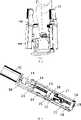
图2是本发明外骨骼并联式踝关节结构示意图,图(a)为侧面示意图,图(b)正面示意图;Fig. 2 is a schematic diagram of the exoskeleton parallel ankle joint structure of the present invention, Figure (a) is a schematic side view, and Figure (b) is a schematic front view;
图3是第一主动支链导杆示意图;Fig. 3 is a schematic diagram of the first active branch chain guide rod;
图4是第三主动支链导杆示意图。Fig. 4 is a schematic diagram of the third active branch chain guide rod.
具体实施方式Detailed ways
下面结合附图对本发明的实施例作详细说明:本实施例在以本发明技术方案为前提下进行实施,给出了详细的实施方式和具体的操作过程,但本发明的保护范围不限于下述的实施例。The embodiments of the present invention are described in detail below in conjunction with the accompanying drawings: this embodiment is implemented on the premise of the technical solution of the present invention, and detailed implementation methods and specific operating procedures are provided, but the protection scope of the present invention is not limited to the following the described embodiment.
本实施例选择3-RPS结构构型,3-RPS结构的示意图如图1所示,静平台1上三点分别为A1、A2、A3,动平台2上三点分别为a1、a2、a3,静平台1的三个转动副分别为


本实施例在3-RPS结构的基础上,根据人体踝关节的运动特点和生理要求,对机构的各关键尺寸进行了优化设计,使其能实现踝关节背屈、跖屈、内翻、外翻运动,并在运动空间和运动特性上都与人体踝关节相类似。In this embodiment, on the basis of the 3-RPS structure, according to the movement characteristics and physiological requirements of the human ankle joint, the key dimensions of the mechanism are optimized so that it can realize ankle dorsiflexion, plantar flexion, varus and valgus It is similar to the human ankle joint in terms of motion space and motion characteristics.
如图2所示,本实施例包括:上平台3、下平台4、足底支撑板5、第一主动支链导杆6、第二主动支链导杆7、第三主动支链导杆8、仿人腿外套11,其中:第一主动支链导杆6、第二主动支链导杆7、第三主动支链导杆8的一端均与上平台3活动连接,第一主动支链导杆6、第二主动支链导杆7、第三主动支链导杆8的另一端均与下平台4活动连接,足底支撑板5由其两边的挡板和下平台4固定连接,仿人腿外套11与上平台3固定连接。As shown in Figure 2, this embodiment includes: an upper platform 3, a lower platform 4, a sole support plate 5, a first active branch chain guide rod 6, a second active branch chain guide rod 7, and a third active branch chain guide rod 8. The human-
所述第一主动支链导杆6、第二主动支链导杆7、第三主动支链导杆8分别通过第一圆柱销101、第二圆柱销102、第三圆柱销103与上平台3连接。The first active chain branch guide rod 6, the second active chain branch guide rod 7, and the third active chain branch guide rod 8 are connected to the upper platform through the first cylindrical pin 101, the second
所述第一主动支链导杆6、第二主动支链导杆7、第三主动支链导杆8分别通过第一球关节轴承901、第二球关节轴承902、第三球关节轴承903与下平台4连接。The first active branch chain guide rod 6, the second active branch chain guide rod 7, and the third active branch chain guide rod 8 pass through the first ball joint bearing 901, the second ball
如图3所示,所述的第一主动支链导杆6,包括:第一伺服电机12、第一连轴器13、第一前轴承支撑座14、第一滚珠丝杆15、第一螺钉16、第一滚珠螺母17、第一后轴承支撑座18、第一轴承19、第一行程开关20、第一L型支撑板21、第一滚珠螺母座22、第一线性滑块23、第一直线导轨24、第一角接触轴承25、第一电机座26,其中:第一伺服电机12的输出轴通过第一连轴器13与第一滚珠丝杆15一端连接,第一伺服电机12固定在第一电机座26上,第一电机座26与第一前轴承支撑座14固接,安装在第一前轴承支撑座14的端面,第一滚珠丝杆15两端通过第一轴承19和第一角接触轴承25支撑,第一轴承19和第一角接触轴承25分别安装在第一后轴承支撑座18和第一前轴承支撑座14上,第一前轴承支撑座14、第一后轴承支撑座18均固定在第一L型支撑板21上,第一滚珠螺母17与第一滚珠丝杆15通过螺纹配合,第一滚珠螺母17与第一滚珠螺母座22通过第一螺钉16相固接,第一滚珠螺母座22的侧面和第一线性滑块23连接,第一直线导轨24安装在第一L型支撑板21的侧面,第一L型支撑板21、第一滚珠螺母座22、第一线性滑块23和第一直线导轨24连接后形成长方形空间,第一行程开关20安装于第一L型支撑板21的侧面,处于长方形空间内,用于检测第一滚珠螺母17所处位置,保护整个装置以免与第一前轴承支撑座14、第一后轴承支撑座18相碰。As shown in Figure 3, the first active branch chain guide 6 includes: a first servo motor 12, a first coupling 13, a first front bearing support 14, a first ball screw 15, a first Screw 16, first ball nut 17, first rear bearing support seat 18, first bearing 19, first travel switch 20, first L-shaped support plate 21, first ball nut seat 22, first linear slider 23, The first linear guide 24, the first angular contact bearing 25, and the first motor base 26, wherein: the output shaft of the first servo motor 12 is connected to one end of the first ball screw 15 through the first coupling 13, and the first servo Motor 12 is fixed on the first motor seat 26, and the first motor seat 26 is fixedly connected with the first front bearing support seat 14, and is installed on the end face of the first front bearing support seat 14, and the first ball screw 15 two ends pass through the first Bearing 19 and the first angular contact bearing 25 supports, and the first bearing 19 and the first angular contact bearing 25 are respectively installed on the first rear bearing support seat 18 and the first front bearing support seat 14, the first front bearing support seat 14, The first rear bearing support seat 18 is all fixed on the first L-shaped support plate 21, the first ball nut 17 and the first ball screw rod 15 are threaded, and the first ball nut 17 and the first ball nut seat 22 pass through the first The screws 16 are fixedly connected, the side of the first ball nut seat 22 is connected with the first linear slider 23, the first linear guide rail 24 is installed on the side of the first L-shaped support plate 21, the first L-shaped support plate 21, the second A ball nut seat 22, the first linear slider 23 and the first linear guide rail 24 are connected to form a rectangular space, and the first travel switch 20 is installed on the side of the first L-shaped support plate 21 in the rectangular space for detecting The position of the first ball nut 17 protects the whole device from colliding with the first front bearing support seat 14 and the first rear bearing support seat 18.
所述的第二主动支链导杆7,包括:第二伺服电机、第二连轴器、第二前轴承支撑座、第二滚珠丝杆、第二螺钉、第二滚珠螺母、第二后轴承支撑座、第二轴承、第二行程开关、第二L型支撑板、第二滚珠螺母座、第二线性滑块、第二直线导轨、第二角接触轴承、第二电机座,上述部件和第一主动支链导杆6的各个部件的连接关系相同。The second active branch chain guide 7 includes: a second servo motor, a second coupling, a second front bearing support seat, a second ball screw, a second screw, a second ball nut, a second rear Bearing support seat, second bearing, second limit switch, second L-shaped support plate, second ball nut seat, second linear slider, second linear guide rail, second angular contact bearing, second motor seat, the above components The connection relationship of each component of the first active branch chain guide rod 6 is the same.
所述第一主动支链导杆6和第二主动支链导杆7分别通过各自的滚珠螺母座由第一球关节轴承901、第二球关节轴承902与下平台4活动连接。The first active branch chain guide rod 6 and the second active branch chain guide rod 7 are movably connected to the lower platform 4 by the first ball joint bearing 901 and the second ball
如图4所示,所述第三主动支链导杆8,包括:第三滚珠丝杆27、第三滚珠螺母28、第三滚珠螺母座29、第三线性滑块30、第三直线导轨31、第三前轴承支撑座32、第三角接触轴承33、第二同步带轮34、同步齿形带35、第一同步带轮36、第三电机座37、第三伺服电机38、第三L型支撑板39、第三行程开关40、第三轴承41、第三后轴承支撑座42,其中:第三伺服电机38固定在第三电机座37上,第三电机座37固定在第三前轴承支撑座32的端面,第三滚珠丝杆27两端通过第三轴承41和第三角接触轴承33支撑,第三轴承41和第三角接触轴承33分别安装在第三后轴承支撑座42和第三前轴承支撑座32上,第三前轴承支撑座32、第三后轴承支撑座42均固定在第三L型支撑板39上,第三滚珠螺母28与第三滚珠丝杆27通过螺纹配合,构成螺旋运动副,第三滚珠螺母28与第三滚珠螺母座29相固接,第三滚珠螺母座29的侧面和第三线性滑块30连接,第三球关节轴承903与第三前轴承支撑座32固接,固定在第三前轴承支撑座32的外侧,第三直线导轨31安装在第三L型支撑板39的侧面,第三L型支撑板39、第三滚珠螺母座29、第三线性滑块30和第三直线导轨31连接后形成长方形空间,第三伺服电机38输出轴和第一同步带轮36连接,第二同步带轮34和第三滚珠丝杆27连接,同步齿形带35分别连接第一同步带轮36和第二同步带轮34,实现第三主动支链导杆8从第三伺服电机38到第三滚珠丝杆27的传动,第三行程开关40安装于第三L型支撑板39的侧面,处于长方形空间内,用于检测第三滚珠螺母28所处位置,保护整个装置以免与第三前轴承支撑座32、第三后轴承支撑座42相碰。As shown in Figure 4, the third active branch chain guide 8 includes: a
所述第三主动支链导杆8通过第三滚珠螺母座29由第三球关节轴承903与下平台4活动连接。The third active branch chain guide rod 8 is movably connected with the lower platform 4 by the third ball joint bearing 903 through the third
所述第一球关节轴承901、第二球关节轴承902、第三球关节轴承903分别与第一主动支链导杆6、第二主动支链导杆7、第三主动支链导杆8采用螺纹孔固接方式和下平台4固接。The first ball joint bearing 901, the second ball
本实施例工作时,对于第一主动支链导杆6,由伺服电机12带动连轴器13转动,然后带动滚珠丝杆15转动,从而使滚珠螺母17沿滚珠丝杆15产生前后移动,最终使与第一主动支链导杆6连接的两端点间的距离发生变化,第二主动支链导杆7的工作过程相同,对于第三主动支链导杆8,由第三伺服电机38带动第一同步带轮36转动,然后经过同步齿形带35传动,带动第二同步带轮34转动,从而带动第三滚珠丝杆27转动,从而使第三滚珠螺母座29沿第三滚珠丝杆27产生前后移动,最终使与第三主动支链导杆8连接的两端点的相对位置发生变化。通过调节连接三条主动支链导杆的两端点的相对位置关系,实现对机构上平台3、下平台4相对位置关系的控制调节。When this embodiment is working, for the first active branch chain guide rod 6, the
本实施例结构具有三个自由度,实现踝关节背屈、跖屈、内翻、外翻运动,同时机构高度可调,能满足不同身高的佩戴者的需求。人体踝关节可实现屈伸和侧翻两种运动,通过屈肌、伸肌、内翻肌和外翻肌共四大肌肉群的拉伸动作来实现踝关节的屈、伸、内翻和外翻运动,本实施例的并联机构的工作原理与其相似。本实施例装置仿照人体关节设计,采用3-RPS并联机构。The structure of this embodiment has three degrees of freedom to realize ankle dorsiflexion, plantarflexion, varus, and valgus movements. At the same time, the height of the mechanism is adjustable to meet the needs of wearers of different heights. The human ankle joint can realize two movements of flexion and extension and rollover. The flexion, extension, varus and valgus of the ankle joint can be realized through the stretching actions of the four major muscle groups of flexors, extensors, varus and valgus Motion, the working principle of the parallel mechanism of this embodiment is similar to it. The device in this embodiment is designed in the manner of human joints, and adopts a 3-RPS parallel mechanism.
Claims (9)
Translated fromChinesePriority Applications (1)
| Application Number | Priority Date | Filing Date | Title |
|---|---|---|---|
| CNB2008100340027ACN100558323C (en) | 2008-02-28 | 2008-02-28 | Parallel type multi-freedom artificial limb exoskeleton ankle joint |
Applications Claiming Priority (1)
| Application Number | Priority Date | Filing Date | Title |
|---|---|---|---|
| CNB2008100340027ACN100558323C (en) | 2008-02-28 | 2008-02-28 | Parallel type multi-freedom artificial limb exoskeleton ankle joint |
Publications (2)
| Publication Number | Publication Date |
|---|---|
| CN101234045Atrue CN101234045A (en) | 2008-08-06 |
| CN100558323C CN100558323C (en) | 2009-11-11 |
Family
ID=39918122
Family Applications (1)
| Application Number | Title | Priority Date | Filing Date |
|---|---|---|---|
| CNB2008100340027AExpired - Fee RelatedCN100558323C (en) | 2008-02-28 | 2008-02-28 | Parallel type multi-freedom artificial limb exoskeleton ankle joint |
Country Status (1)
| Country | Link |
|---|---|
| CN (1) | CN100558323C (en) |
Cited By (24)
| Publication number | Priority date | Publication date | Assignee | Title |
|---|---|---|---|---|
| CN101596139B (en)* | 2009-06-29 | 2011-01-12 | 浙江大学 | Three-degree-of-freedom ankle-assisted motion exoskeleton |
| CN102397118A (en)* | 2010-09-19 | 2012-04-04 | 上海理工大学 | Bionic ankle joint |
| CN102499854A (en)* | 2011-11-18 | 2012-06-20 | 上海电机学院 | Parallel structure type ankle joint rehabilitation training device |
| CN102670377A (en)* | 2012-05-28 | 2012-09-19 | 西华大学 | Exoskeleton wearable lower limb rehabilitation training robot device |
| CN102973338A (en)* | 2012-12-07 | 2013-03-20 | 上海交通大学 | Active-passive type ankle joint prosthesis and movement mode thereof |
| CN103006357A (en)* | 2012-12-19 | 2013-04-03 | 南京工程学院 | Active-passive combined low-power-consumption ankle joint prosthesis |
| CN103211670A (en)* | 2013-04-12 | 2013-07-24 | 西南交通大学 | Assistant exoskeleton ankle joint joining device |
| CN103816028A (en)* | 2014-01-28 | 2014-05-28 | 浙江大学 | Active and passive ankle joint combination training rehabilitation system |
| CN104983541A (en)* | 2015-07-10 | 2015-10-21 | 哈尔滨天愈康复医疗机器人有限公司 | Wrist rehabilitation therapy robot based on spatial parallel drive |
| CN104983547A (en)* | 2015-07-10 | 2015-10-21 | 哈尔滨天愈康复医疗机器人有限公司 | Three-degree-of-freedom wearable ankle rehabilitation medical robot |
| CN105012056A (en)* | 2015-06-01 | 2015-11-04 | 北京航空航天大学 | Structure body of lower extremity exoskeleton with bionic knee joint |
| CN105310862A (en)* | 2015-07-26 | 2016-02-10 | 广东铭凯医疗机器人有限公司 | Ankle joint rehabilitation training device |
| CN106880427A (en)* | 2017-04-10 | 2017-06-23 | 周佰利 | A kind of artificial limb machinery foot that can quickly walk |
| CN108095869A (en)* | 2018-02-20 | 2018-06-01 | 郭双伟 | A kind of medical multifunctional artificial limb |
| CN108186172A (en)* | 2018-02-20 | 2018-06-22 | 郭双伟 | A kind of quick walking artificial thigh of folding wheel type intelligence |
| CN108245373A (en)* | 2018-01-15 | 2018-07-06 | 北京工业大学 | A kind of ankle joint rehabilitation device of six cradle heads axis junction |
| CN108309694A (en)* | 2018-03-02 | 2018-07-24 | 哈工大机器人(合肥)国际创新研究院 | A kind of foot drive-type lower limb rehabilitation training device |
| CN108542703A (en)* | 2018-03-05 | 2018-09-18 | 北京工业大学 | A kind of double UPS types ankle joint rehabilitation devices |
| CN108652813A (en)* | 2017-03-23 | 2018-10-16 | 本田技研工业株式会社 | Ankle-joint mechanism |
| CN109223440A (en)* | 2018-09-11 | 2019-01-18 | 佳木斯大学 | A kind of parallel institution ankle device for rehabilitation |
| CN109939415A (en)* | 2019-04-17 | 2019-06-28 | 福州大学 | An active parallel rehabilitation machine with high movement angle and its assembling method |
| CN110353949A (en)* | 2019-08-08 | 2019-10-22 | 北京交通大学 | A kind of active knee ankle-joint prosthetic device based on change born of the same parents' parallel institution |
| CN110613586A (en)* | 2019-09-17 | 2019-12-27 | 中北大学 | Lower limb rehabilitation robot |
| CN114939010A (en)* | 2022-04-12 | 2022-08-26 | 上海交通大学 | Full-freedom bionic ankle foot prosthesis |
Family Cites Families (1)
| Publication number | Priority date | Publication date | Assignee | Title |
|---|---|---|---|---|
| FR1531562A (en)* | 1967-05-23 | 1968-07-05 | Portable device for intermittent elongations |
- 2008
- 2008-02-28CNCNB2008100340027Apatent/CN100558323C/ennot_activeExpired - Fee Related
Cited By (37)
| Publication number | Priority date | Publication date | Assignee | Title |
|---|---|---|---|---|
| CN101596139B (en)* | 2009-06-29 | 2011-01-12 | 浙江大学 | Three-degree-of-freedom ankle-assisted motion exoskeleton |
| CN102397118A (en)* | 2010-09-19 | 2012-04-04 | 上海理工大学 | Bionic ankle joint |
| CN102499854A (en)* | 2011-11-18 | 2012-06-20 | 上海电机学院 | Parallel structure type ankle joint rehabilitation training device |
| CN102499854B (en)* | 2011-11-18 | 2014-04-09 | 上海电机学院 | Parallel structure type ankle joint rehabilitation training device |
| CN102670377A (en)* | 2012-05-28 | 2012-09-19 | 西华大学 | Exoskeleton wearable lower limb rehabilitation training robot device |
| CN102973338A (en)* | 2012-12-07 | 2013-03-20 | 上海交通大学 | Active-passive type ankle joint prosthesis and movement mode thereof |
| CN102973338B (en)* | 2012-12-07 | 2015-07-15 | 上海交通大学 | Active-passive type ankle joint prosthesis and movement mode thereof |
| CN103006357B (en)* | 2012-12-19 | 2015-04-22 | 南京工程学院 | Active-passive combined low-power-consumption ankle joint prosthesis |
| CN103006357A (en)* | 2012-12-19 | 2013-04-03 | 南京工程学院 | Active-passive combined low-power-consumption ankle joint prosthesis |
| CN103211670A (en)* | 2013-04-12 | 2013-07-24 | 西南交通大学 | Assistant exoskeleton ankle joint joining device |
| CN103211670B (en)* | 2013-04-12 | 2015-01-28 | 西南交通大学 | Assistant exoskeleton ankle joint joining device |
| CN103816028A (en)* | 2014-01-28 | 2014-05-28 | 浙江大学 | Active and passive ankle joint combination training rehabilitation system |
| CN103816028B (en)* | 2014-01-28 | 2015-12-02 | 浙江大学 | A kind of ankle joint active-passive composite training rehabilitation system |
| CN105012056A (en)* | 2015-06-01 | 2015-11-04 | 北京航空航天大学 | Structure body of lower extremity exoskeleton with bionic knee joint |
| CN104983541B (en)* | 2015-07-10 | 2017-10-10 | 哈尔滨天愈康复医疗机器人有限公司 | A kind of Spatial Parallel drives wrist robots for rehabilitation therapy |
| CN104983541A (en)* | 2015-07-10 | 2015-10-21 | 哈尔滨天愈康复医疗机器人有限公司 | Wrist rehabilitation therapy robot based on spatial parallel drive |
| CN104983547A (en)* | 2015-07-10 | 2015-10-21 | 哈尔滨天愈康复医疗机器人有限公司 | Three-degree-of-freedom wearable ankle rehabilitation medical robot |
| CN105310862A (en)* | 2015-07-26 | 2016-02-10 | 广东铭凯医疗机器人有限公司 | Ankle joint rehabilitation training device |
| CN108652813B (en)* | 2017-03-23 | 2020-12-29 | 本田技研工业株式会社 | Ankle Mechanism |
| CN108652813A (en)* | 2017-03-23 | 2018-10-16 | 本田技研工业株式会社 | Ankle-joint mechanism |
| CN106880427B (en)* | 2017-04-10 | 2018-09-07 | 泰山医学院 | A kind of artificial limb machinery foot that can quickly walk |
| CN106880427A (en)* | 2017-04-10 | 2017-06-23 | 周佰利 | A kind of artificial limb machinery foot that can quickly walk |
| CN108245373B (en)* | 2018-01-15 | 2020-05-08 | 北京工业大学 | Ankle joint rehabilitation device with six crossed rotary joint axes |
| CN108245373A (en)* | 2018-01-15 | 2018-07-06 | 北京工业大学 | A kind of ankle joint rehabilitation device of six cradle heads axis junction |
| CN108186172A (en)* | 2018-02-20 | 2018-06-22 | 郭双伟 | A kind of quick walking artificial thigh of folding wheel type intelligence |
| CN108095869A (en)* | 2018-02-20 | 2018-06-01 | 郭双伟 | A kind of medical multifunctional artificial limb |
| CN108309694A (en)* | 2018-03-02 | 2018-07-24 | 哈工大机器人(合肥)国际创新研究院 | A kind of foot drive-type lower limb rehabilitation training device |
| CN108309694B (en)* | 2018-03-02 | 2023-12-19 | 合肥哈工力训智能科技有限公司 | Foot-driven lower limb rehabilitation training device |
| CN108542703A (en)* | 2018-03-05 | 2018-09-18 | 北京工业大学 | A kind of double UPS types ankle joint rehabilitation devices |
| CN108542703B (en)* | 2018-03-05 | 2021-04-30 | 北京工业大学 | Ankle joint rehabilitation device |
| CN109223440A (en)* | 2018-09-11 | 2019-01-18 | 佳木斯大学 | A kind of parallel institution ankle device for rehabilitation |
| CN109939415B (en)* | 2019-04-17 | 2023-11-17 | 福州大学 | Active parallel rehabilitation machine with high movement angle and assembly method thereof |
| CN109939415A (en)* | 2019-04-17 | 2019-06-28 | 福州大学 | An active parallel rehabilitation machine with high movement angle and its assembling method |
| CN110353949A (en)* | 2019-08-08 | 2019-10-22 | 北京交通大学 | A kind of active knee ankle-joint prosthetic device based on change born of the same parents' parallel institution |
| CN110613586A (en)* | 2019-09-17 | 2019-12-27 | 中北大学 | Lower limb rehabilitation robot |
| CN110613586B (en)* | 2019-09-17 | 2025-01-28 | 中北大学 | Lower limb rehabilitation robot |
| CN114939010A (en)* | 2022-04-12 | 2022-08-26 | 上海交通大学 | Full-freedom bionic ankle foot prosthesis |
Also Published As
| Publication number | Publication date |
|---|---|
| CN100558323C (en) | 2009-11-11 |
Similar Documents
| Publication | Publication Date | Title |
|---|---|---|
| CN100558323C (en) | Parallel type multi-freedom artificial limb exoskeleton ankle joint | |
| CN100558322C (en) | Parallel articulated walking exoskeleton prosthesis for paralyzed patients | |
| CN102499854B (en) | Parallel structure type ankle joint rehabilitation training device | |
| CN101999970B (en) | Parallel Multi-DOF Ankle Joint Rehabilitation Trainer | |
| CN101810533B (en) | walking aid exoskeleton rehabilitation robot | |
| CN101623547B (en) | Lower limb rehabilitation medical robot used for paralytic patient | |
| CN209059884U (en) | A wearable lower limb rehabilitation robot | |
| CN110353949B (en) | An active knee-ankle joint prosthesis mechanism based on metamorphic parallel mechanism | |
| CN109009866A (en) | Sitting type lower limb exoskeleton rehabilitation robot | |
| CN102028604B (en) | Parallel type ankle rehabilitation training apparatus | |
| CN104644377B (en) | A sitting and lying lower limb rehabilitation device | |
| Zeng et al. | A new type of ankle-foot rehabilitation robot based on muscle motor characteristics | |
| CN204484679U (en) | A kind of sitting and lying formula recovery set for lower limbs | |
| CN100571660C (en) | prosthetic exoskeleton knee joint | |
| Jiang et al. | Research status on ankle rehabilitation robot | |
| CN112494270A (en) | Robot system for assisting in lower limb movement of coma patient | |
| Jamwal et al. | Design and transparency assessment of a gait rehabilitation robot with biomimetic knee joints | |
| CN101647736A (en) | Parallel-connection ectoskeleton knee joint | |
| CN106943282A (en) | A kind of polypody power-assisted healing robot | |
| CN108392378B (en) | Lower limb rehabilitation training exoskeleton system and its walking control method and hip joint structure | |
| CN117338572A (en) | A multi-muscle cooperatively driven ankle-foot exoskeleton robot | |
| CN215504125U (en) | An upper limb exoskeleton rehabilitation robot with ten degrees of freedom and interchangeable left and right hands | |
| Li et al. | Design of 6-DOF parallel ankle rehabilitation robot | |
| CN115154190A (en) | A rope-driven sitting and lying lower limb rehabilitation robot | |
| Lu et al. | Mechanism Design and Analysis of a Multi-DOF Flexible Ankle Rehabilitation Robot |
Legal Events
| Date | Code | Title | Description |
|---|---|---|---|
| C06 | Publication | ||
| PB01 | Publication | ||
| C10 | Entry into substantive examination | ||
| SE01 | Entry into force of request for substantive examination | ||
| C14 | Grant of patent or utility model | ||
| GR01 | Patent grant | ||
| ASS | Succession or assignment of patent right | Owner name:JIANGSU XINZHIYUAN MEDICAL ROBOTS CO., LTD. Free format text:FORMER OWNER: SHANGHAI JIAOTONG UNIVERSITY Effective date:20120518 | |
| C41 | Transfer of patent application or patent right or utility model | ||
| COR | Change of bibliographic data | Free format text:CORRECT: ADDRESS; FROM: 200240 MINHANG, SHANGHAI TO: 225300 TAIZHOU, JIANGSU PROVINCE | |
| TR01 | Transfer of patent right | Effective date of registration:20120518 Address after:225300 Jiangsu province Taizhou City Medical City Road No. 1 Building 1 layer H Patentee after:Jiangsu maslech medical robot Co Ltd Address before:200240 Dongchuan Road, Shanghai, No. 800, No. Patentee before:Shanghai Jiao Tong University | |
| ASS | Succession or assignment of patent right | Owner name:JIANGSU MASLECH MDEICAL TECHNOLOGY CO., LTD. Free format text:FORMER OWNER: JIANGSU XINZHIYUAN MEDICAL ROBOTS CO., LTD. Effective date:20121224 | |
| C41 | Transfer of patent application or patent right or utility model | ||
| TR01 | Transfer of patent right | Effective date of registration:20121224 Address after:225300 Jiangsu city of Taizhou Province medicine City No. 8 Room 407, room 707 Patentee after:JIANGSU MASLECH MEDICAL TECHNOLOGY CO., LTD. Address before:225300 Jiangsu province Taizhou City Medical City Road No. 1 Building 1 layer H Patentee before:Jiangsu maslech medical robot Co Ltd | |
| CF01 | Termination of patent right due to non-payment of annual fee | Granted publication date:20091111 Termination date:20150228 | |
| EXPY | Termination of patent right or utility model |