CN101233329A - Method for joining metal plates or the like and grinding machine - Google Patents
Method for joining metal plates or the like and grinding machineDownload PDFInfo
- Publication number
- CN101233329A CN101233329ACNA2006800279992ACN200680027999ACN101233329ACN 101233329 ACN101233329 ACN 101233329ACN A2006800279992 ACNA2006800279992 ACN A2006800279992ACN 200680027999 ACN200680027999 ACN 200680027999ACN 101233329 ACN101233329 ACN 101233329A
- Authority
- CN
- China
- Prior art keywords
- plate
- mentioned
- metal plates
- joining
- grinding
- Prior art date
- Legal status (The legal status is an assumption and is not a legal conclusion. Google has not performed a legal analysis and makes no representation as to the accuracy of the status listed.)
- Granted
Links
Images


Classifications
- F—MECHANICAL ENGINEERING; LIGHTING; HEATING; WEAPONS; BLASTING
- F16—ENGINEERING ELEMENTS AND UNITS; GENERAL MEASURES FOR PRODUCING AND MAINTAINING EFFECTIVE FUNCTIONING OF MACHINES OR INSTALLATIONS; THERMAL INSULATION IN GENERAL
- F16B—DEVICES FOR FASTENING OR SECURING CONSTRUCTIONAL ELEMENTS OR MACHINE PARTS TOGETHER, e.g. NAILS, BOLTS, CIRCLIPS, CLAMPS, CLIPS OR WEDGES; JOINTS OR JOINTING
- F16B11/00—Connecting constructional elements or machine parts by sticking or pressing them together, e.g. cold pressure welding
- F16B11/006—Connecting constructional elements or machine parts by sticking or pressing them together, e.g. cold pressure welding by gluing
- B—PERFORMING OPERATIONS; TRANSPORTING
- B24—GRINDING; POLISHING
- B24B—MACHINES, DEVICES, OR PROCESSES FOR GRINDING OR POLISHING; DRESSING OR CONDITIONING OF ABRADING SURFACES; FEEDING OF GRINDING, POLISHING, OR LAPPING AGENTS
- B24B23/00—Portable grinding machines, e.g. hand-guided; Accessories therefor
- B24B23/04—Portable grinding machines, e.g. hand-guided; Accessories therefor with oscillating grinding tools; Accessories therefor
Landscapes
- Engineering & Computer Science (AREA)
- Mechanical Engineering (AREA)
- General Engineering & Computer Science (AREA)
- Vehicle Cleaning, Maintenance, Repair, Refitting, And Outriggers (AREA)
- Connection Of Plates (AREA)
- Standing Axle, Rod, Or Tube Structures Coupled By Welding, Adhesion, Or Deposition (AREA)
Abstract
Description
Translated fromChinese技术领域technical field
本发明涉及一种金属板等的接合方法及打磨机,其适用于例如车体等金属板的损伤部、以及建筑物、机械等的非铁金属或非金属制的周壁的损伤部的修补,特别是可将具有复杂的弯曲面的板体的接合部或修补部接合形成平面或立体的一致平面,并使其达到精密且美观的效果,同时,也使该种接合作业合理且便于施行。The present invention relates to a method for joining metal plates, etc., and a grinder, which are suitable for repairing damaged parts of metal plates such as car bodies, and damaged parts of non-ferrous metal or non-metal peripheral walls of buildings and machinery, etc. In particular, it is possible to form a flat or three-dimensional consistent plane by joining the joint or repaired part of the plate body with complex curved surfaces, and achieve a precise and beautiful effect. At the same time, it also makes this joint operation reasonable and easy to implement.
背景技术Background technique
例如,在接合金属板时,一般情况下采用将金属板重叠或对接、或者将接头板紧贴于接合的金属板上进行焊接、以及采用铆钉或螺纹固定的方法。For example, when joining metal plates, generally, methods of overlapping or butting the metal plates, welding the joint plate against the joined metal plates, and fixing with rivets or screws are generally used.
但是,会产生如下问题:焊接时金属板发生热变形而产生残余应力;铆接时会由于瞬间的点压而在铆接孔周围产生冲击变形和残余应力,并且由于接合精度或接合后的变形问题而导致不稳定;另外,螺纹固定时的螺钉嵌入作业比较繁杂;并且,无论哪种情况都会产生焊接痕或铆钉、螺钉露出等外观不良的问题。However, there will be the following problems: the thermal deformation of the metal plate during welding will cause residual stress; the impact deformation and residual stress will be generated around the riveting hole due to instantaneous point pressure during riveting, and due to the problem of joint accuracy or deformation after joint. Instability is caused; in addition, screw insertion work during screwing is complicated; and in any case, problems of poor appearance such as weld marks or exposed rivets and screws will occur.
因此,在上述常用的接合方法中,无法对应例如要求表面高度匀整化的车体损伤部的修补。Therefore, the conventional joining method described above cannot cope with, for example, the repair of a damaged portion of a vehicle body that requires a highly uniform surface.
即,作为车体损伤部的修补形式,有时需要切除损伤部位,并在该切除部接合修补用部件;在进行上述修补时,若采用上述普通的技术接合修补用部件,会在修补部表面产生变形,有损于表面的匀整化和外观,因此不能采用上述的接合技术。That is, as a form of repairing a damaged part of a car body, sometimes it is necessary to cut off the damaged part and join the repairing parts at the cut part; Deformation, detrimental to the leveling and appearance of the surface, so the above-mentioned joining techniques cannot be used.
因此,通常的做法是将包括损伤部的车体部件替换成新部件进行对应,在该种修补方法中,需要将与车体部件相邻接的其它部件例如车窗玻璃、保险杠等进行拆装,工序繁琐,并且维修费用较高,因此该种方法不合理。Therefore, it is common practice to replace the car body parts including the damaged parts with new ones. The process is cumbersome and the maintenance cost is high, so this method is unreasonable.
这样,申请人开发出一种方法,并已提出申请;其将包括车体损伤部位的一定范围进行部分切除,并在不会影响表面匀整化的情况下,采用胶粘剂比较方便地将已准备好的修补部件进行接合。In this way, the applicant has developed a method and has filed an application; it will partially remove a certain range including the damaged part of the car body, and under the condition that the surface will not be affected, it will be more convenient to use an adhesive The repair parts are bonded.
即,申请人所提出的金属板的接合方法为,将一组金属板的端部磨边加工成锥形状,并在其附近位置形成可将自攻螺钉螺入的螺钉孔,并将其开口部形成滑动钵状,与金属板的接合端部相对配置,并在其里面涂布胶粘剂粘接护板。That is, the method of joining the metal plates proposed by the applicant is to grind the ends of a group of metal plates into a tapered shape, form a screw hole in the vicinity of which a self-tapping screw can be screwed, and open it. The part is formed into a sliding bowl shape, and is arranged opposite to the joint end part of the metal plate, and the adhesive is coated on the inside to bond the guard plate.
并且,当上述胶粘剂稍一硬化时,将上述自攻螺钉螺入螺钉孔,并将该螺钉孔、以及上述金属板端部间的凹部填充胶粘剂,在遮蔽了上述螺钉头部的同时,使金属板的接合部分匀整化,在外观上形成如同没有接合部的单一金属板一样(例如,参照专利文件1)。And when the above-mentioned adhesive hardens slightly, the above-mentioned self-tapping screw is screwed into the screw hole, and the recess between the screw hole and the above-mentioned metal plate ends is filled with adhesive, while covering the above-mentioned screw head, the metal The joint portion of the plate is uniformed, and is formed like a single metal plate without a joint portion in appearance (for example, refer to Patent Document 1).
另外,作为金属板接合方法的其它形式,将一侧的金属板的端部磨边加工成锥形状,并在其附近位置形成可将自攻螺钉螺入的螺钉孔,并在另一侧金属板的缘部形成台阶部,并将其向里面侧弯折而形成重叠部,利用该重叠部代替上述的护板,将其配置于上述一侧金属板的端部里面侧,并在该金属板的里面涂布胶粘剂粘接配置重叠部。In addition, as another form of the metal plate joining method, the end of the metal plate on one side is ground into a tapered shape, and a screw hole into which a self-tapping screw can be screwed is formed near it, and a metal plate is formed on the other side. The edge of the plate forms a stepped portion, and it is bent toward the back side to form an overlapping portion, and the overlapping portion is used to replace the above-mentioned guard plate, and it is arranged on the back side of the end portion of the metal plate on the one side, and on the metal Adhesive is applied to the back surface of the board and the overlapping portion is bonded.
并且,同时提出如下方案,当上述胶粘剂稍一硬化时,将上述自攻螺钉螺入螺钉孔,并将该螺钉孔、以及上述金属板的磨边加工部与端缘之间的凹部填充同样的胶粘剂,在遮蔽了上述螺钉头部的同时,使金属板的接合部分匀整化,在外观上形成如同没有接合部的单一金属板一样。And, at the same time, it is proposed that when the above-mentioned adhesive hardens slightly, the above-mentioned self-tapping screw is screwed into the screw hole, and the screw hole and the recess between the edge-grinding part and the edge of the above-mentioned metal plate are filled with the same The adhesive hides the above-mentioned screw head and at the same time makes the joint part of the metal plate uniform, forming the same appearance as a single metal plate without a joint part.
但是,上述申请人所提出的接合方法需要自攻螺钉和形成相对于金属板的螺钉孔,增加了部件的数量,同时也增加了螺钉孔的加工作业,不利于生产。However, the joining method proposed by the applicant above requires self-tapping screws and the formation of screw holes relative to the metal plate, which increases the number of components and also increases the processing of screw holes, which is not conducive to production.
另外,例如汽车车体上所使用的,在同步接合薄钢板时,需要长度为螺钉头部可埋入螺钉孔内的自攻螺钉,并且若自攻螺钉不是以约50mm的间距配置的话,相对于接合材料为胶粘剂,不会取得良好的按压状态。In addition, for example, as used in automobile bodies, when simultaneously joining thin steel plates, self-tapping screws with a length such that the screw heads can be embedded in the screw holes are required, and if the self-tapping screws are not arranged at a pitch of about 50mm, relatively Since the bonding material is an adhesive, a good pressing state cannot be obtained.
为了满足上述条件,必须使用特别定做的自攻螺钉,并且,在一系列的接合作业中,需要进行螺钉孔的开孔作业或自攻螺钉的螺入作业、以及胶粘剂的填充作业等,产生作业繁杂费时等问题。In order to meet the above conditions, it is necessary to use custom-made self-tapping screws, and in a series of joining operations, it is necessary to perform drilling operations for screw holes, screwing operations for self-tapping screws, and filling operations for adhesives, etc., resulting in work. Complicated and time-consuming issues.
另外,上述的接合方法中,通过自攻螺钉将各金属板端部的接头部压力均匀地进行紧固比较困难,若用力紧固一端,则该接头部比另一端的接头部陷入,在左右的接头部产生高度差,因此将两端的金属板端部接合为一致平面比较困难。In addition, in the above-mentioned joining method, it is difficult to tighten the joints at the ends of the metal plates with self-tapping screws with uniform pressure. There is a difference in height at the joint part of the joint, so it is difficult to join the ends of the metal plates at both ends into a uniform plane.
因此,在左右的金属板端部形成高度差时,在包括金属板区间的台阶侧的金属板的表面抹上腻子使其匀整化,不仅作业复杂,而且从外部能感觉到焊接痕,影响外观。Therefore, when there is a difference in height between the left and right metal plate ends, it is not only complicated to apply putty on the surface of the metal plate on the step side including the metal plate section to make it even, but also weld marks can be felt from the outside, which affects the appearance. .
为解决上述问题,提出一种板金修补方法(例如,参照专利文献2);将包括汽车车体的损伤部分的一定部分去除,并使该板金的端部形成锥形状,在将该锥形的弯曲部形成R状的同时,准备比上述去除部分面积稍大的修补部件,将该修补部件的端部利用专用的修理工具弯折成形,并通过胶粘剂将该弯折部接合配置于上述板金端部的里侧,在修补部件和板金端部之间的凹部抹入腻子,然后涂装修补部件、板金以及腻子的表面。In order to solve the above problems, a sheet metal repair method is proposed (for example, refer to Patent Document 2); a certain part including the damaged part of the automobile body is removed, and the end of the sheet metal is formed into a tapered shape, and the tapered While forming the bent part into an R shape, prepare a repair part with a slightly larger area than the above-mentioned removed part, bend and shape the end of the repair part with a special repair tool, and connect the bent part to the above-mentioned sheet metal end with an adhesive On the inner side of the part, apply putty to the recess between the repaired part and the end of the sheet metal, and then paint the surface of the repaired part, sheet metal, and putty.
但是,该板金修补方法通过形成锥形部的R状可防止修补痕露出,但是没有考虑到填充于该部分中的填充剂的温度膨胀,因此,产生例如在夏季填充剂膨胀、修补痕露出而影响外观的问题。However, this sheet metal repair method can prevent the repair marks from being exposed by forming an R-shape of the tapered part, but it does not take into account the temperature expansion of the filler filled in this part. Problems affecting appearance.
另外,上述的修补方法中,由于仅通过胶粘剂将板金接合配置于弯折部,因此会由于弯折部尺寸的不均匀和胶粘剂的或多或少而不能够得到接合板金的一致平面性,另外由于其质量也具有多样性,因此不能够得到接合部的匀整化和漂亮的外观。特别是,接合部分为复杂的三维弯曲面的情况下,接合部较差的平面性和匀整性更加明显,因此希望进行改进。In addition, in the above-mentioned repairing method, since the sheet metal is only bonded to the bent portion with an adhesive, it is impossible to obtain uniform planarity of the joined sheet metal due to the uneven size of the bent portion and the amount of adhesive. Since the quality also varies, it is not possible to obtain uniformity and a good appearance of the joint portion. In particular, when the joint portion is a complex three-dimensional curved surface, the poor planarity and uniformity of the joint portion are more pronounced, so improvement is desired.
此外,修补车体损伤部时,在修补部件与车体端部之间的凹部填充腻子,该腻子在固化后进行涂装,并打磨使其与车体形成一致平面,作为该所述的腻子打磨装置,一般使用打磨机。In addition, when repairing the damaged part of the car body, fill the recess between the repaired part and the end of the car body with putty, paint the putty after curing, and polish it to form a consistent plane with the car body, as the putty The grinding device generally uses a grinding machine.
在上述的打磨机中,有一种皮带打磨机,其包括粗加工磨头和精加工磨头,各磨头具有缠绕在皮带轮上的驱动旋转的环状的打磨带,以及配置于该打磨带内的衬垫单元;该衬垫单元包括,进退自由地设置于打磨带上的托座;驱动该托座的气缸;自由转动地支承托座的衬垫;以及,将该衬垫在所期望的角度上定位的电动机。上述衬垫包括,相正交的两个平坦部分、以及配置于该平坦部分间角部的曲面部分。在平坦面或凸状的曲面,被打磨面选择衬垫的平坦部分;在凹状的曲面,被打磨面选择衬垫的曲面部分;在该选择部分按压打磨带,打磨被打磨面(例如,参照专利文献3)。Among the above-mentioned grinding machines, there is a belt grinding machine, which includes a roughing grinding head and a finishing grinding head, each grinding head has an endless grinding belt wound on a pulley and driven to rotate, and is arranged in the grinding belt. The pad unit; the pad unit includes a bracket that is freely advanced and retreated on the grinding belt; a cylinder that drives the bracket; a pad that supports the bracket freely; Angularly positioned motors. The spacer includes two orthogonal flat parts and a curved part disposed at a corner between the flat parts. On a flat or convex surface, the surface to be ground selects the flat portion of the pad; on a concave surface, the surface to be ground selects the curved portion of the pad; press the belt on the selected portion, and the surface to be ground is ground (for example, see Patent Document 3).
但是,上述的皮带打磨机中,衬垫曲面部分的曲率限定为一种,并通过气缸使其作直线移动,仅需简单地压入打磨带,因此被打磨面形成复杂的弯曲面,其曲率也发生各种变化,产生不能够对应车体曲面部分的打磨的问题。However, in the above-mentioned belt grinder, the curvature of the curved surface of the pad is limited to one type, and the cylinder moves it in a straight line, and the grinding belt only needs to be simply pressed in, so the surface to be polished forms a complex curved surface, and its curvature Various changes have also occurred, and there has been a problem that it cannot cope with the polishing of the curved surface portion of the car body.
为解决上述问题,提出一种皮带打磨机(例如,参照专利文献4),将具有可挠性的弹性部件组成的两个衬垫本体互相重合,并将其在长度方向上可相对移动地结合而构成衬垫,支承该衬垫,并将其压入打磨带从而打磨被打磨面。In order to solve the above problems, a belt grinder (for example, refer to Patent Document 4) is proposed, in which two pad bodies composed of flexible elastic parts are superimposed on each other and combined in a relatively movable manner in the length direction And constitute a pad, support the pad, and press it into the grinding belt to polish the surface to be polished.
但是,由于上述皮带打磨机用手来支承衬垫进行作业,因此产生了下述问题:工作负担较大难以进行长时间的作业,同时,衬垫本体具有可挠性,因此为了使衬垫本体保持所希望的曲率,需要手指进行细微的操作,增加了手指的负担,并且作业需要熟练操作。However, since the above-mentioned belt sander supports the pad by hand for operation, the following problems have occurred: the work load is large and it is difficult to perform long-term work. At the same time, the pad body has flexibility, so in order to make the pad body Maintaining the desired curvature requires fine manipulation of the fingers, which increases the burden on the fingers and requires skillful operation.
专利文献1:特许第3187782号公报Patent Document 1: Patent No. 3187782
专利文献2:WO00/32352号公报Patent Document 2: WO00/32352 Publication
专利文献3:特开昭59-53155号公报Patent Document 3: JP-A-59-53155
专利文献4:特开2001-300840号公报Patent Document 4: JP-A-2001-300840
发明内容Contents of the invention
发明想要解决的问题The problem the invention seeks to solve
本发明为了解决上述问题,目的在于提供一种金属板等的结合方法以及打磨机,其适用于例如车体等金属板的损伤部、以及建筑物、机械等的非铁金属或非金属制的周壁的损伤部的修补,特别是将具有复杂的弯曲面的板体的接合部或修补部进行平面或立体的接合形成一致平面,并使其达到精密且美观的效果,同时,也使该种接合作业合理且便于施行。In order to solve the above-mentioned problems, the present invention aims to provide a method for bonding metal plates and the like, and a grinding machine, which are suitable for damaged parts of metal plates such as car bodies, and non-ferrous or non-metallic parts such as buildings and machines. The repair of the damaged part of the surrounding wall, especially the joint part or the repair part of the plate body with a complex curved surface, is joined in a plane or three-dimensional way to form a consistent plane, and to achieve a precise and beautiful effect. At the same time, this kind of The joining operation is reasonable and easy to implement.
解决问题的方法way of solving the problem
本发明的金属板等的结合方法中,将互相接合的两个金属板的接合端部在板厚方向或与板厚垂直的方向分开配置,将与上述金属板一体或分体的接合片配置在上述接合端部的一侧,并将上述接合端部和接合片粘结;在上述胶粘剂硬化前,将压板覆盖于上述接合端部的另一侧的表面配置,并在该压板的表面设置具有磁力的吸附工具,通过该吸附工具的磁力,使上述压板与上述接合端部的另一侧表面紧贴,并且通过上述磁力吸引上述接合端部变位,并使上述两个接合端部侧表面以上述压板为基准形成一致平面,并将上述金属板的接合部接合为平面或立体上的一致平面,从而使接合部匀整化,获得精密且漂亮的外观。In the joining method of metal plates and the like according to the present invention, the joining ends of the two metal plates to be joined to each other are arranged separately in the direction of the plate thickness or in a direction perpendicular to the plate thickness, and the joining pieces integral or separate from the metal plates are arranged. On one side of the above-mentioned joint end, and bond the above-mentioned joint end and the joint piece; before the above-mentioned adhesive is hardened, a pressure plate is covered on the surface of the other side of the above-mentioned joint end, and the surface of the pressure plate is installed A suction tool having a magnetic force, the above-mentioned pressure plate is brought into close contact with the surface of the other side of the above-mentioned joint end by the magnetic force of the suction tool, and the above-mentioned joint end is attracted by the above-mentioned magnetic force to displace, and the above-mentioned two joint end sides The surface forms a consistent plane with the above-mentioned pressing plate as a reference, and the joint part of the above-mentioned metal plate is joined to a plane or three-dimensional consistent plane, so that the joint part is evened, and a precise and beautiful appearance is obtained.
另外,在本发明的金属板等的接合方法中,将两个接合端部侧表面形成平面或弯曲状的一致平面,可以获得从平坦面到复杂的弯曲面多种接合面的一致平面。In addition, in the joining method of metal plates and the like according to the present invention, the side surfaces of the two joining ends are formed into flat or curved matching planes, and it is possible to obtain matching planes of various joining surfaces ranging from flat surfaces to complicated curved surfaces.
另外,在本发明的金属板等的接合方法中,采用比透磁率小的部件形成上述压板,可使磁力透过上述压板,防止该磁力的衰减,同时,可以获得利用磁力产生的接合面的一致性。In addition, in the joining method of metal plates and the like according to the present invention, by forming the above-mentioned press plate with a member having a smaller magnetic permeability, the magnetic force can be transmitted through the above-mentioned press plate, and attenuation of the magnetic force can be prevented. consistency.
在本发明的金属板等的接合方法中,可使上述压板在板厚方向上弯曲,容易沿着弯曲的接合部发生弯曲,从而获得弯曲的接合面的一致平面。In the joining method of metal plates and the like according to the present invention, the press plate can be bent in the direction of plate thickness to easily bend along the bent joining portion, thereby obtaining a uniform plane of the bent joining surfaces.
此外,在本发明的金属板等的接合方法中,覆盖于上述接合端部另一侧的表面,邻接配置有多个压板,可促使压板的弯曲,容易实现弯曲的接合部的平面一致化。In addition, in the method of joining metal plates and the like according to the present invention, a plurality of pressing plates are arranged adjacently to cover the surface on the other side of the joint end portion, so that the bending of the pressing plates can be accelerated, and the planar alignment of the bent joining portion can be easily achieved.
此外,在本发明的金属板等的接合方法中,在上述压板的里面安装非粘结薄板,可防止由吸引变位的金属板所挤出的胶粘剂附着于压板,便于进行压板的摘取。In addition, in the joining method of metal plates etc. of the present invention, the non-adhesive thin plate is installed on the back of the above-mentioned press plate, which can prevent the adhesive extruded by the suction-displaced metal plate from adhering to the press plate, and facilitate the removal of the press plate.
在本发明的金属板等的接合方法中,在上述压板上设置一个或多个吸附工具,可将压板高效且正确地固定安装。In the method for joining metal plates and the like according to the present invention, one or more suction tools are provided on the press plate, so that the press plate can be efficiently and accurately fixed and attached.
另外,在本发明的金属板等的接合方法中,上述接合端部侧表面形成一致平面后,使上述胶粘剂硬化,而确保上述接合端部的吸引变位,同时,可以切实地得到接合端部的一致平面的状态。In addition, in the method for joining metal plates and the like according to the present invention, after the side surfaces of the joint ends are formed to be flat, the adhesive is cured to ensure suction displacement of the joint ends and at the same time, it is possible to securely obtain the joint ends. The state of the consistent plane.
另外,在本发明的金属板等的接合方法中,上述接合端部侧表面形成一致平面后,由于在上述胶粘剂硬化后摘取上述压板,可便于进行相对于金属板间的填充剂的填充。In addition, in the method of joining metal plates and the like according to the present invention, after the side surfaces of the joint ends are formed to be flat, the pressing plate can be removed after the adhesive has hardened to facilitate the filling of the filler between the metal plates.
在本发明的金属板等的接合方法中,摘下上述压板后,在上述结合端部的另一侧的金属板间填充填充剂,以保持接合端部表面的一致平面的状态。In the method of joining metal plates and the like according to the present invention, after removing the pressing plate, a filler is filled between the metal plates on the other side of the joint end to keep the surface of the joint end in a uniform state.
另外,在本发明的金属板等的接合方法中,最迟在填充填充剂前,将填充有填充剂的金属板间的至少表面侧的角部形成微小的弯曲状;可以防止在修补之后上述角部的线突出到外侧,显现出接合痕。In addition, in the method for joining metal plates and the like according to the present invention, before filling the filler at the latest, at least the corners on the surface side between the metal plates filled with the filler are formed into a slightly curved shape; The lines at the corners protrude to the outside, showing seam marks.
此外,在本发明的金属板等的接合方法中,上述填充剂的线膨胀系数尽可能地小,以控制填充剂的膨胀和收缩,防止例如在夏季时填充剂的膨胀导致的胀出,并防止显现出接合痕。In addition, in the joining method of metal plates and the like of the present invention, the coefficient of linear expansion of the above-mentioned filler is as small as possible to control the expansion and contraction of the filler, prevent swelling caused by the expansion of the filler in summer, for example, and Prevents the appearance of joint marks.
在本发明的金属板等的接合方法中,上述的吸附工具在コ字形的截面的钢板制的壳体内安装磁铁块而构成,从而提出吸附工具的具体结构。此外,在本发明的金属板等的接合方法中,将上述壳体的端缘由磁铁块的端面突出设置,使磁力从上述端缘高效地放出,使吸附工具稳定地固定。In the method of joining metal plates and the like according to the present invention, the above-mentioned adsorption tool is constituted by attaching a magnet block to a case made of steel plate having a U-shaped cross section, and a specific structure of the adsorption tool is proposed. In addition, in the joining method of metal plates and the like according to the present invention, the edge of the housing is protruded from the end surface of the magnet block, and magnetic force is efficiently released from the edge to stably fix the suction tool.
此外,在本发明的金属板等的接合方法中,在上述吸附工具设置把持部,从而可以简单地操作吸附工具。In addition, in the method for joining metal plates and the like according to the present invention, the suction tool can be easily handled by providing a holding portion on the suction tool.
在本发明的金属板等的接合方法中,用把手连接多个吸附工具,从而便于操作吸附工具。In the joining method of metal plates and the like according to the present invention, a plurality of suction tools are connected by handles, thereby facilitating handling of the suction tools.
另外,在本发明的金属板等的接合方法中,在上述填充剂硬化后,用打磨机平滑地进行打磨,可便于打磨填充剂的表面。In addition, in the joining method of metal plates and the like according to the present invention, after the above-mentioned filler is hardened, it is smoothed with a grinder, so that the surface of the filler can be easily polished.
在本发明的金属板等的接合方法中,将互相接合的两个金属板的接合端部在板厚方向或与板厚垂直的方向分开配置,将与上述金属板一体或分体的接合片配置在上述接合端部的一侧,并将上述接合端部和接合片粘结,同时,将上述板体的至少一端采用螺纹固定于上述接合片上;在该板体接合方法中,在上述螺钉中使用薄厚头部的自攻螺钉,在上述胶粘剂硬化后,打磨上述螺钉的头部,并且使上述螺钉留置于上述板体的接合端部,由自攻螺钉实现板体的固定,同时,利用自攻螺钉的接合强度,将金属、非铁金属、非金属等各种板体合理且稳固地接合。In the method for joining metal plates and the like according to the present invention, the joint end portions of the two metal plates to be joined to each other are arranged separately in the direction of plate thickness or in a direction perpendicular to the plate thickness, and the joining piece integral or separate from the metal plates is It is arranged on one side of the above-mentioned joint end, and the above-mentioned joint end is bonded to the joint piece, and at the same time, at least one end of the above-mentioned plate body is fixed on the above-mentioned joint piece by screws; in the plate body joint method, the above-mentioned screw In this method, self-tapping screws with thin and thick heads are used. After the above-mentioned adhesive is hardened, the head of the above-mentioned screw is polished, and the above-mentioned screw is left at the joint end of the above-mentioned plate body, and the plate body is fixed by the self-tapping screw. At the same time, use The joint strength of self-tapping screws can reasonably and firmly join various boards such as metals, non-ferrous metals, and non-metals.
另外,在本发明的金属板等的接合方法中,将上述螺钉的头部进行平滑地打磨,从而使该头部的打磨面和上述接合端部的表面形成一致的平面,并进行接合端部的面的涂装。In addition, in the method of joining metal plates and the like according to the present invention, the head of the above-mentioned screw is smoothly ground so that the ground surface of the head and the surface of the joint end part form a plane that coincides with the surface of the joint end part, and the joint end part surface coating.
此外,在本发明的金属板等的接合方法中,将上述螺钉头部的打磨面和上述接合端部的表面形成一致的平面后,涂装该表面,并合理地涂装接合端部的表面。In addition, in the joining method of the metal plates etc. of this invention, after making the ground surface of the said screw head and the surface of the said joint end part coincide with a plane, this surface is painted, and the surface of the joint end part is coated rationally. .
本发明的打磨机具有驱动部、以及与该驱动部联动可保持打磨薄板的打磨板,将上述打磨板设置为可向板厚方向弯曲,沿着弯曲的被打磨面的弯曲面容易使打磨板弯曲,从而可实现该部位的打磨。The grinding machine of the present invention has a driving unit, and a grinding plate that can hold a thin plate for grinding in conjunction with the driving unit, and the above-mentioned grinding plate is arranged to be bendable in the thickness direction of the plate, and the grinding plate can be easily moved along the curved surface of the curved surface to be polished. Bend, so that the grinding of this part can be realized.
另外,在本发明的打磨机中,将上述打磨板在打磨方向上形成细长状,并使该打磨板可在其长度方向上作往复直线动作,谋求打磨板的小型轻量化,确保良好的操作性,同时,可实现在狭小的空间内进行打磨。In addition, in the grinding machine of the present invention, the above-mentioned grinding plate is formed into an elongated shape in the grinding direction, and the grinding plate can be reciprocated and linearly moved in its length direction, so as to achieve small size and light weight of the grinding plate and ensure good durability. Operability, at the same time, enables sanding in a small space.
此外,在本发明的打磨机中,按压上述打磨板的前端部,可使该打磨板沿着被打磨部的表面移动,可沿着弯曲的被打磨面的弯曲面操作打磨板,从而进行打磨。In addition, in the grinding machine of the present invention, pressing the front end of the above-mentioned grinding plate can move the grinding plate along the surface of the part to be polished, and the grinding plate can be operated along the curved surface of the curved surface to be polished to perform grinding. .
在本发明的打磨机中,设有可设置上述驱动部的摇动架,在该摇动架的对向位置可自由摇动地与摇杆连接,将保持板在板厚方向上可转动地与该摇杆的端部连接,并将上述打磨板在板厚方向上可弯曲地安装在该保持板间,根据被打磨面使打磨板变位,可精密地打磨被打磨面。In the grinding machine of the present invention, there is provided a rocking frame on which the above-mentioned drive unit can be provided, and the position facing the rocking frame is connected to the rocker in a freely rockable manner, and the holding plate is rotatably connected to the rocker in the thickness direction. The ends of the rods are connected, and the above-mentioned grinding plate is installed between the holding plates so as to be bendable in the thickness direction, and the grinding plate is displaced according to the surface to be polished, so that the surface to be polished can be polished precisely.
另外,在本发明的打磨机中,通过上述摇杆的动作,并使上述打磨板可朝向其长度方向和宽度方向动作,并根据各种的打磨方向和多样的打磨条件,可得到精密且多样的打磨面。In addition, in the grinding machine of the present invention, through the movement of the above-mentioned rocker, the above-mentioned grinding plate can be moved towards its length direction and width direction, and according to various grinding directions and various grinding conditions, precise and diverse grinding can be obtained. polished surface.
另外,在本发明的打磨机中,将上述驱动部设置为可振动,并通过该驱动部的振动将摇动架和摇杆设置为可联动,从而可利用振动实现打磨。In addition, in the grinding machine of the present invention, the above-mentioned driving part is provided to be vibrated, and the rocking frame and the rocker are provided to be linked by the vibration of the driving part, so that grinding can be realized by vibration.
在本发明的打磨机中,上述驱动部可把持地突出在摇动架上,提高了打磨机的操作性,并由此而便于使用。In the grinder according to the present invention, the above-mentioned driving portion protrudes from the swing frame so as to be grippable, so that the operability of the grinder is improved, and thus it is easy to use.
另外,在本发明的打磨机中,按压上述驱动部,并使上述打磨薄板沿着被打磨部的表面可变位,从而便于进行相对于各种被打磨面的打磨。In addition, in the sander of the present invention, the driving unit is pressed to displace the sanding sheet along the surface of the portion to be sanded, thereby facilitating sanding on various surfaces to be sanded.
发明效果Invention effect
本发明的金属板等的接合方法,在胶粘剂硬化前,将压板覆盖于上述接合端部的另一侧的表面配置,并在该压板的表面设置具有磁力的吸附工具,通过该吸附工具的磁力,使上述压板与上述接合端部的另一侧表面紧贴,并且通过上述磁力吸引上述接合端部变位,并使上述两个接合端部侧表面以上述压板为基准形成一致平面,并将上述金属板的接合部接合为平面或立体上的一致平面,从而使接合部匀整化,获得精密且漂亮的外观。In the method for joining metal plates and the like according to the present invention, before the adhesive is hardened, a pressing plate is arranged to cover the surface on the other side of the above-mentioned joint end, and a suction tool having a magnetic force is provided on the surface of the pressing plate, and the magnetic force of the suction tool is passed. , the above-mentioned pressure plate is closely attached to the other side surface of the above-mentioned joint end part, and the above-mentioned joint end part is attracted to be displaced by the above-mentioned magnetic force, and the side surfaces of the two joint end parts form a consistent plane with the above-mentioned pressure plate as a reference, and The joints of the above metal plates are jointed into a plane or a three-dimensional consistent plane, so that the joints are uniform and a precise and beautiful appearance is obtained.
另外,在本发明的金属板等的接合方法中,将上述两个接合端面的侧表面形成平面或弯曲状的一致平面,可以获得从平坦面到复杂的弯曲面多种接合面的一致平面。In addition, in the method for joining metal plates and the like according to the present invention, the side surfaces of the two joining end surfaces are formed into flat or curved coincident planes, and various conforming planes of joint surfaces ranging from flat surfaces to complicated curved surfaces can be obtained.
另外,在本发明的金属板等的接合方法中,采用比透磁率小的部件形成上述压板,由于使吸附工具的磁力透过上述压板,可使磁力透过压板而防止该磁力的衰减,同时,可以获得利用磁力产生的接合面的一致平面。In addition, in the joining method of metal plates and the like of the present invention, the above-mentioned press plate is formed by using a member having a smaller magnetic permeability, and since the magnetic force of the suction tool is transmitted through the above-mentioned press plate, the magnetic force can be transmitted through the press plate to prevent the attenuation of the magnetic force, and at the same time , a consistent plane of the mating surface produced using magnetic force can be obtained.
在本发明的金属板等的接合方法中,可使上述压板在板厚方向上弯曲,容易沿着弯曲的接合部发生弯曲,从而获得弯曲的接合面的一致平面。In the joining method of metal plates and the like according to the present invention, the press plate can be bent in the direction of plate thickness to easily bend along the bent joining portion, thereby obtaining a uniform plane of the bent joining surfaces.
此外,在本发明的金属板等的接合方法中,穿过上述接合端部另一侧的表面,邻接配置有多个压板,可促使压板的弯曲,便于对应弯曲的接合面。In addition, in the method for joining metal plates and the like according to the present invention, a plurality of pressing plates are arranged adjacent to each other through the surface on the other side of the joining end portion, so that the bending of the pressing plates can be facilitated, and it is easy to correspond to the curved joining surface.
此外,在本发明的金属板等的接合方法中,在上述压板的里面安装非粘结薄板,可防止由吸引变位的接合端部所挤出的胶粘剂附着于压板,便于进行压板的摘取。In addition, in the joining method of metal plates and the like according to the present invention, a non-adhesive thin plate is installed on the back of the above-mentioned press plate, which can prevent the adhesive extruded from the joint end portion of the suction displacement from adhering to the press plate, and facilitate the removal of the press plate. .
在本发明的金属板等的接合方法中,在上述压板上设置多个吸附工具,可将压板高效且正确地固定安装。In the method of joining metal plates and the like according to the present invention, a plurality of suction tools are provided on the above-mentioned press plate, so that the press plate can be efficiently and accurately fixed and attached.
另外,在本发明的金属板等的接合方法中,上述接合端部侧表面形成一致平面后,由于上述胶粘剂硬化,而确保上述接合端部的吸引变位,同时,可以切实地得到接合端部的一致平面的状态。In addition, in the method for joining metal plates and the like according to the present invention, after the side surfaces of the joint ends are formed into a uniform plane, since the adhesive hardens, the suction displacement of the joint ends is ensured, and at the same time, the joint end can be reliably obtained. The state of the consistent plane.
另外,在本发明的金属板等的接合方法中,上述接合端部侧表面形成一致平面后,由于上述胶粘剂硬化后摘取上述压板,可便于进行相对于金属板间的填充剂的填充。In addition, in the method of joining metal plates and the like according to the present invention, after the side surfaces of the joint ends are formed to be flat, the pressing plate can be removed after the adhesive hardens, thereby facilitating the filling of the filler between the metal plates.
在本发明的金属板等的接合方法中,摘下上述压板后,在上述接合端部的另一侧的金属板间填充填充剂,以保持接合端部表面的外观。In the method of joining metal plates and the like according to the present invention, after removing the pressing plate, a filler is filled between the metal plates on the other side of the joint end to maintain the appearance of the surface of the joint end.
另外,在本发明的金属板等的接合方法中,最迟在填充填充剂前,将填充有上述填充剂的金属板间的至少表面侧的角部形成微小的弯曲状;可以防止在修补之后上述角部的线突出到外侧,显现出接合痕。In addition, in the method for joining metal plates and the like according to the present invention, before filling the filler at the latest, at least the corners on the surface side between the metal plates filled with the filler are formed into a slightly curved shape; The line of the above-mentioned corner protrudes to the outside, and the seam mark appears.
此外,在本发明的金属板等的接合方法中,上述填充剂的线膨胀系数尽可能地小,以控制填充剂的膨胀和收缩,防止例如在夏季时填充剂的膨胀导致的胀出,防止显现出接合痕。In addition, in the method for joining metal plates and the like according to the present invention, the linear expansion coefficient of the above-mentioned filler is as small as possible to control the expansion and contraction of the filler, prevent swelling caused by the expansion of the filler in summer, for example, and prevent Shows seam marks.
在本发明的金属板等的接合方法中,上述的吸附工具在コ字形的截面的钢板制的壳体内安装磁铁块而构成,从而提出吸附工具的具体结构。In the method of joining metal plates and the like according to the present invention, the above-mentioned adsorption tool is constituted by attaching a magnet block to a case made of steel plate having a U-shaped cross section, and a specific structure of the adsorption tool is proposed.
此外,在本发明的金属板等的接合方法中,将上述壳体的端缘由磁铁块的端面突出设置,使磁力从上述端缘高效地放出,使吸附工具稳定地固定。In addition, in the joining method of metal plates and the like according to the present invention, the edge of the housing is protruded from the end surface of the magnet block, and magnetic force is efficiently released from the edge to stably fix the suction tool.
此外,在本发明的金属板等的接合方法中,在上述吸附工具设置把持部,从而可以简单地操作多个吸附工具。In addition, in the joining method of metal plates and the like according to the present invention, a plurality of suction tools can be easily handled by providing a holding portion on the suction tool.
在本发明的金属板等的接合方法中,用把手连接多个吸附工具,从而便于操作吸附工具。In the joining method of metal plates and the like according to the present invention, a plurality of suction tools are connected by handles, thereby facilitating handling of the suction tools.
另外,在本发明的金属板等的接合方法中,在上述填充剂硬化后,用打磨机平滑地进行打磨,可便于打磨填充剂的表面。In addition, in the joining method of metal plates and the like according to the present invention, after the above-mentioned filler is hardened, it is smoothed with a grinder, so that the surface of the filler can be easily polished.
在本发明的金属板等的接合方法中,在上述螺钉中使用薄厚头部的自攻螺钉,在上述胶粘剂硬化后,打磨上述螺钉的头部,并且使上述螺钉留置于上述板体的接合端部,由自攻螺钉实现板体的固定,同时,利用自攻螺钉的接合强度,将金属、非铁金属、非金属等各种板体合理且稳固地接合。In the method of joining metal plates and the like according to the present invention, a self-tapping screw with a thin head is used as the screw, and after the adhesive is hardened, the head of the screw is ground, and the screw is left at the joint end of the plate body. In the first part, the plate body is fixed by self-tapping screws, and at the same time, various plate bodies such as metal, non-ferrous metal, and non-metal are reasonably and firmly joined by using the joint strength of self-tapping screws.
另外,在本发明的金属板等的接合方法中,将上述螺钉的头部进行平滑地打磨,从而使该头部的打磨面和上述接合端部的表面形成一致的平面,并进行残留有自攻螺钉的接合端部的面的涂装。In addition, in the method of joining metal plates and the like according to the present invention, the head of the screw is smoothly ground so that the ground surface of the head and the surface of the joint end part form a flat surface, and the self-contained surface remains. Coating of the joint end surface of the tapping screw.
此外,在本发明的金属板等的接合方法中,将上述螺钉头部的打磨面和上述接合端部的表面形成一致的平面后,涂装该表面,并合理地涂装接合端部的表面。In addition, in the joining method of the metal plates etc. of this invention, after making the ground surface of the said screw head and the surface of the said joint end part coincide with a plane, this surface is painted, and the surface of the joint end part is coated rationally. .
本发明的打磨机将上述打磨板设置为可向板厚方向弯曲,沿着弯曲的被打磨面的弯曲面容易使打磨板弯曲,从而便于对应弯曲面的打磨。In the grinding machine of the present invention, the above-mentioned grinding plate is arranged to be bendable in the plate thickness direction, and the grinding plate is easily bent along the curved surface of the curved surface to be polished, thereby facilitating grinding corresponding to the curved surface.
另外,在本发明的打磨机中,将上述打磨板在打磨方向上形成细长状,并使该打磨板可在其长度方向上作往复直线动作,谋求打磨板的小型轻量化,确保良好的操作性,同时,可实现在狭小的空间内进行打磨。In addition, in the grinding machine of the present invention, the above-mentioned grinding plate is formed into an elongated shape in the grinding direction, and the grinding plate can be reciprocated and linearly moved in its length direction, so as to achieve small size and light weight of the grinding plate and ensure good durability. Operability, at the same time, enables sanding in a small space.
此外,在本发明的打磨机中,按压上述打磨板的前端部,可使该打磨板沿着被打磨部的表面移动,可沿着弯曲的被打磨面的弯曲面操作打磨板,从而进行打磨。In addition, in the grinding machine of the present invention, pressing the front end of the above-mentioned grinding plate can move the grinding plate along the surface of the part to be polished, and the grinding plate can be operated along the curved surface of the curved surface to be polished to perform grinding. .
在本发明的打磨机中,设有可设置上述驱动部的摇动架,在该摇动架的对向位置可自由摇动地与摇杆连接,将保持板在板厚方向上可转动地与该摇杆的端部连接,并将上述打磨板在板厚方向上可弯曲地安装在该保持板间,根据被打磨面使打磨板变位,可精密地打磨被打磨面。In the grinding machine of the present invention, there is provided a rocking frame on which the above-mentioned drive unit can be provided, and the position facing the rocking frame is connected to the rocker in a freely rockable manner, and the holding plate is rotatably connected to the rocker in the thickness direction. The ends of the rods are connected, and the above-mentioned grinding plate is installed between the holding plates so as to be bendable in the thickness direction, and the grinding plate is displaced according to the surface to be polished, so that the surface to be polished can be polished precisely.
另外,在本发明的打磨机中,通过上述摇杆的动作,并使上述打磨板可朝向其长度方向和宽度方向动作,并根据各种的打磨方向和多样的打磨条件,可得到精密且美观的打磨面。In addition, in the grinding machine of the present invention, the above-mentioned grinding plate can be moved toward its length direction and width direction through the movement of the above-mentioned rocker, and according to various grinding directions and various grinding conditions, precise and beautiful surfaces can be obtained. polished surface.
另外,在本发明的打磨机中,将上述驱动部设置为可振动,并通过该驱动部的振动将摇动架和摇杆设置为可联动,从而可利用振动实现打磨。In addition, in the grinding machine of the present invention, the above-mentioned driving part is provided to be vibrated, and the rocking frame and the rocker are provided to be linked by the vibration of the driving part, so that grinding can be realized by vibration.
在本发明的打磨机中,上述驱动部可把持地突出在摇动架上,提高了打磨机的操作性,并由此而便于使用。In the grinder according to the present invention, the above-mentioned driving portion protrudes from the swing frame so as to be grippable, so that the operability of the grinder is improved, and thus it is easy to use.
另外,在本发明的打磨机中,按压上述驱动部,并使上述打磨薄板沿着被打磨部的表面可变位,从而便于进行相对于各种被打磨面的打磨。In addition, in the sander of the present invention, the driving unit is pressed to displace the sanding sheet along the surface of the portion to be sanded, thereby facilitating sanding on various surfaces to be sanded.
附图说明Description of drawings
图1表示应用本发明的以车体上具有损伤部的汽车为修补对象的正视图;Fig. 1 represents the front view of applying the present invention to the automobile with the damaged part on the car body as the repair object;
图2为扩大表示应用本发明的接合部的主要部位的立体图;FIG. 2 is an enlarged perspective view showing the main parts of the junction to which the present invention is applied;
图3为扩大表示本发明所述接合部的修补状况的主要部位的立体图,在接合端部的表面配置压板;Fig. 3 is an enlarged perspective view showing the main part of the repair condition of the joint according to the present invention, and a pressing plate is arranged on the surface of the joint end;
图4为扩大表示本发明所述接合部的修补状况的主要部位的立体图,在配置于接合端部表面的压板上设置吸附工具;Fig. 4 is an enlarged perspective view showing the main parts of the repairing condition of the joint according to the present invention, and an adsorption tool is arranged on the pressure plate arranged on the surface of the joint end;
图5为扩大表示使用本发明接合方法的吸附工具的立体图;Fig. 5 is an enlarged perspective view showing a suction tool using the bonding method of the present invention;
图6为扩大表示本发明所述接合部的修补状况的主要部位的剖视图,将接合端部在板厚方向上隔开配置,并在其间涂布胶粘剂,同时,在配置于其表面的压板上设置吸附工具;Fig. 6 is an enlarged cross-sectional view of main parts showing the state of repair of the joint according to the present invention. The joint ends are arranged at intervals in the thickness direction, and an adhesive is applied between them, and at the same time, the pressing plate arranged on the surface Set the snapping tool;
图7为扩大表示本发明所述接合部的修补状况的主要部位的剖视图,将接合端部在板厚方向上隔开配置,并且还表示其接合端部在板厚方向上隔开配置的情况下的修补状况;Fig. 7 is an enlarged cross-sectional view of main parts showing the state of repair of the joint according to the present invention, the joint ends are spaced apart in the plate thickness direction, and the state in which the joint ends are spaced apart in the plate thickness direction is also shown repair status under
图8为扩大表示本发明所述接合部的修补状况的主要部位的剖视图,将接合端部在板厚方向上隔开配置,并且还表示其接合端部在与图7相反方向上隔开配置的情况下的修补状况;Fig. 8 is an enlarged cross-sectional view of main parts showing the state of repair of the joint according to the present invention, the joint ends are spaced apart in the plate thickness direction, and the joint ends are spaced apart in the direction opposite to that of Fig. 7 the repair status in the case of
图9为扩大表示本发明所述接合部的修补状况的主要部位的剖视图,将接合端部在板厚方向上隔开配置,并且还表示在其接合端部的一侧形成不同形状的情况下的修补状况;Fig. 9 is an enlarged cross-sectional view of main parts showing the state of repair of the joint according to the present invention, the joint ends are arranged at intervals in the plate thickness direction, and a case where a different shape is formed on one side of the joint end is also shown repair status;
图10为扩大表示本发明所述接合部的修补状况的主要部位的剖视图,其表示将配置在接合端部表面的压板摘下,在其空隙部涂布填充剂的状况;10 is an enlarged cross-sectional view of main parts showing the state of repair of the joint according to the present invention, which shows the state of removing the pressure plate arranged on the surface of the joint end and applying a filler to the gap;
图11为扩大表示本发明所述接合部的修补状况的主要部位的剖视图,其表示用打磨机打磨填充于接合端部表面空隙部的填充剂的状况;Fig. 11 is an enlarged cross-sectional view showing the main part of the repair condition of the joint according to the present invention, which shows the condition of grinding the filler filled in the surface void of the joint end with a grinder;
图12表示适用于打磨本发明填充剂的打磨机的正视图;Figure 12 represents the front view of the grinding machine suitable for grinding the filler of the present invention;
图13为图12的俯视图;Figure 13 is a top view of Figure 12;
图14为表示适用于打磨本发明填充剂的打磨机的使用状态的剖视图,其表示弯曲的被打磨部的打磨状况;Fig. 14 is a cross-sectional view showing the state of use of the grinder suitable for grinding the filler of the present invention, which shows the grinding condition of the curved portion to be ground;
图15为表示本发明第二实施例的立体图,表示将两个金属板对接配置,并在接合端部的表面配置压板,在其表面设置吸附工具的状况;Fig. 15 is a perspective view showing the second embodiment of the present invention, showing the situation in which two metal plates are butt-jointed, and a pressure plate is arranged on the surface of the joint end, and an adsorption tool is arranged on the surface;
图16是图15的截面图;Fig. 16 is a sectional view of Fig. 15;
图17为扩大表示上述第二实施例中接合部修补状况的主要部位的剖视图,其表示从图16的状态摘下压板,在其空隙部涂布填充剂的状况;Fig. 17 is an enlarged cross-sectional view of main parts showing the state of joint repair in the second embodiment, which shows a state in which the pressure plate is removed from the state of Fig. 16 and a filler is applied to the gap;
图18为扩大表示上述第二实施例中接合部修补状况的主要部位的剖视图,其表示从图17的状态采用打磨机打磨填充剂的状况;Fig. 18 is an enlarged cross-sectional view showing the main parts of the state of joint repair in the above second embodiment, which shows the state of using a grinder to polish the filler from the state of Fig. 17;
图19为表示本发明第三实施例的立体图,采用把手连接两个吸附工具;Fig. 19 is a perspective view showing a third embodiment of the present invention, using a handle to connect two adsorption tools;
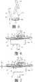
图20为表示本发明第四实施例的立体图,将两个板体隔开配置,在其里面涂布胶粘剂,并将接合片重叠配置,从其表面侧螺入自攻螺钉而对其固定;Fig. 20 is a perspective view showing a fourth embodiment of the present invention, two boards are separated and arranged, an adhesive is applied inside, and the joining pieces are overlapped and arranged, and self-tapping screws are screwed in from the surface side to fix it;
图21为沿图20中A-A线的扩大剖视图,利用打磨机将自攻螺钉的扁平的头部打磨去除;Figure 21 is an enlarged cross-sectional view along line A-A in Figure 20, using a grinder to remove the flat head of the self-tapping screw;
图22表示将自攻螺钉的头部去除后,将填充剂涂布于空隙部分,并将其表面涂布形成一致平面的状况;Figure 22 shows that after the head of the self-tapping screw is removed, the filler is applied to the void, and the surface is coated to form a uniform plane;
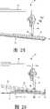
图23表示本发明第五实施例所述打磨机的正视图,并表示其使用状态;Fig. 23 shows the front view of the grinder according to the fifth embodiment of the present invention, and shows its state of use;
图24为扩大表示图23主要部位的剖视图,其表示摇动架与摇杆、保持板与打磨板的安装状况;Figure 24 is a sectional view showing the main parts of Figure 23 enlargedly, which shows the installation conditions of the rocking frame and the rocking bar, the holding plate and the grinding plate;
图25为扩大表示图23主要部位的剖视图,其详细地表示摇动架与摇杆、保持板与打磨板的安装状况。Fig. 25 is an enlarged sectional view showing the main parts of Fig. 23, which shows in detail the installation conditions of the rocking frame and the rocking bar, the holding plate and the grinding plate.
符号说明Symbol Description
2金属板(车体侧)2 metal plates (body side)
4a、4b、9a微小弯曲部4a, 4b, 9a Minor bends
5金属板(修补部件)5 metal plates (repair parts)
6、31接合片(接合材料)6, 31 bonding piece (bonding material)
10胶粘剂10 adhesive
12压板12 platen
13非连接薄板13 Non-connected sheets
15吸附工具15 adsorption tool
16壳体16 housing
17磁铁块17 magnet blocks
18把持部18 control department
19填充剂19 Fillers
20打磨机20 grinder
22打磨板22 grinding plate
28被打磨部28 polished part
29打磨薄板29 sanding sheet
32把手32 handles
34自攻螺钉34 self-tapping screws
34a头部34a head
35涂装部35 Painting Department
36摇动架36 rocking frame
37驱动部(振动装置)37 drive unit (vibration device)
39摇杆39 Rocker
具体实施方式Detailed ways
下面,针对应用汽车车体损伤部的修补法的图示的实施例来说明本发明;图1至图11中,1表示修补对象的汽车,在其车体2的被修补侧板体5的一部位具有损伤部3。Below, the present invention will be described for the illustrated embodiment of the method of repairing the damaged part of the automobile body; among Fig. One part has a damaged
在修补上述损伤部3时,首先采用适当的工具将上述损伤部3切除形成适当的形状,并采用适当的工具(图示省略)将其切除部周边向内侧弯曲呈倾斜状,在其表面形成椎状的开口面4。When repairing the above-mentioned
上述开口面4在上述被修补侧板体5的板厚和后述的胶粘剂的涂布厚度的相加部分弯曲形成台阶部,将其平坦切除部的端缘侧弯曲成与被修补侧板体5大致平行,从而形成与上述被修补侧板体5一体的接合片即接合材料6。The opening
在上述开口面4的表面侧,即外侧的弯曲部和内侧的弯曲部,通过上述工具或别的工具形成R状的微小的弯曲部4a、4b。On the surface side of the opening
另外,准备了与上述车体2的被修补侧板体5同质且同厚的金属板制的修补侧板体7,将该修补侧板体7由上述切除部的形状形成若干小型的相似形状或除去损伤部3的该车体部件的上述切除部的形状。In addition, a repaired
上述修补侧板体7在其端部周围具有和上述接合材料6大致等宽度的接合材料8,在其端缘形成与上述开口面4同样锥状的开口面9,并通过上述工具或其他的工具在其表面侧形成与上述同样的R状的微小弯曲部9a。The above-mentioned repaired
此时,上述开口面4、9不限于锥状,将其表面侧的角部形成R状也可以,或不是在最初的时候形成上述微小弯曲部4a、4b、9a,而是在将后述的填充剂填充入空隙11前形成也可,另外,在该实施例中,在被修补侧板体5形成弯曲部,与此相反,在被修补侧板体7形成弯曲部也可。At this time, the above-mentioned opening surfaces 4, 9 are not limited to the tapered shape, and the corners on the surface side may be formed in an R shape, or the above-mentioned slightly
之后,将胶粘剂10涂布于上述接合材料6的表面,在该胶粘剂10上将接合材料8重叠,并通过空隙11将上述车体2侧的被修补侧板体5的开口面4和接合材料8的开口面9相对配置,在上述胶粘剂10硬化之前通过压板12保持该种状态。After that, the adhesive 10 is applied to the surface of the above-mentioned
作为胶粘剂10,在实施例中采用以环氧树脂为主体的主剂和硬化剂构成。As the adhesive 10, in the embodiment, a main agent mainly composed of epoxy resin and a curing agent are used.
上述压板12采用比透磁率小的铝板等金属板或合成树脂板,并将这些沿着车体2或修补侧板体7的平面配置,或者沿着弯曲面形成可弯曲的薄厚,在其里面贴附聚乙烯薄膜等的非粘接薄板13。The above-mentioned
在上述压板12表面的中央沿纵向形成有指标线14,将该指标线14位于被修补侧板体5和修补侧板体7的接合端部中央,便可将上述压板12配置成左右均等。An
此时,作为可使压板12沿着被修补侧板体5或修补侧板体7的弯曲面弯曲的其它方法,也可在压板12的纵横的多个位置设置切口部或颈部(同时图示省略),使其容易弯曲,或将压板12形成为较窄宽度或短小状,并将其配置多个。At this time, as another method that can make the
然后,在上述压板12上,覆盖被修补侧板体5和修补侧板体7的接合部配置多个或单个的吸附工具15。Then, on the above-mentioned
上述吸附工具15由比透磁率较高的钢板制的壳体16、以及固定于该壳体16的内部的、重量较轻且具有较大磁力的永磁铁构成的磁铁块17组成,上述壳体16为将钢板弯曲形成大致为コ字形的截面,并使其弯曲片16a的端缘比磁铁块17稍稍突出,从而可形成磁极,e为该突出量。Above-mentioned
图中,18为突设于壳体16中央的大致为T字形状的把持部,从而可保持吸附工具15。In the figure, 18 is a substantially T-shaped holding portion protruding from the center of the
这样,在上述吸附工具15中,弯曲片16a、16a的端缘与压板12紧密结合,由磁铁块1 7放射出的磁力线由弯曲片16a、16a的端缘透过压板12,从其里面侧的被修补侧板体5和接合材料8形成经由空隙11磁力线回路。In this way, in the above-mentioned
并且,上述胶粘剂10硬化期间,吸引里面侧的被修补侧板体5的端部和接合材料8使其变位,并将这些表面以压板12为基准面可形成一致平面的状态。And, while the above-mentioned
这样,例如图7所示,在被修补侧板体5的接合部所形成的弯曲部形成得较浅,或者涂布较多的胶粘剂10,修补侧板体7的接合材料8比被修补侧板体5向外侧突出,在被修补侧板体5和压板12之间存在微小间隙S1时,被修补侧板体5被吸附工具15吸引变位,朝向箭头方向即表面侧移动,接合材料8侧保持与压板12的最初吸附状态,并将被修补侧板体5和接合材料8的表面形成一致平面的状态。In this way, for example, as shown in FIG. 7 , the curved portion formed at the joint portion of the repaired
由此,在接合材料6和8之间形成一定厚度的粘接层10。Thus, an
然后,胶粘剂10硬化,被修补侧板体5和接合材料8的表面保持一致平面的状态,并通过上述一定厚度的粘接层10获得一定的粘接强度。Then, the adhesive 10 hardens, and the surfaces of the repaired
此时,被修补侧板体5侧被吸附工具15吸引变位,胶粘剂10的一部分被挤出到空隙11,由于该胶粘剂10与非粘接薄板13接触,避免了与压板12的接触,因此,不会发生在胶粘剂10硬化后不能摘下压板12的问题。At this time, the repaired
另外,胶粘剂10的一部分被挤入到接合材料6的端部和修补侧板体7的里面,从而强化其紧固力,此外,即使如上述将胶粘剂10挤出,由于其位于被修补侧板体5和修补侧板体7的里面侧,因此不会影响到上述板体5、7的表面外观。In addition, a part of the adhesive 10 is squeezed into the end of the
此外,和上述相反,例如在被修补侧板体5的接合部所形成的弯曲部形成得较深,或者涂布少量的胶粘剂10,被修补侧板体5比接合材料8向外侧突出,如图8所示在接合材料8和压板12之间存在微小间隔S2时,接合材料8侧被吸附工具15吸引而变位,向箭头方向即表面侧移动,被修补侧板体5侧保持与压板12最初的吸附状态,使被修补侧板体5和接合材料8的表面形成一致平面的状态。In addition, contrary to the above, for example, the bent portion formed at the joint portion of the repaired
这样,在接合材料6、8之间形成一定厚度的粘接层10。In this way, an
然后,胶粘剂10硬化,被修补侧板体5和接合材料8的表面形成一致平面的状态,另外,通过上述一定厚度的粘接层10获得一定的粘接强度。Then, the adhesive 10 is hardened, and the surfaces of the repaired
此时,即使修补侧板体7如上所述吸引变位,只要胶粘剂10的涂布量不是特别少,就不会妨碍胶粘剂10的粘接。At this time, even if the repaired
此外,即使是在如图9所示的接合材料6的弯曲加工较差、接合材料6和接合材料8不是平行的情况下,通过覆盖被修补侧板体5和接合材料8架设压板12,并在此配置吸附工具15,而吸附被修补侧板体5和接合材料8使其变位,从而形成一致平面的状态,在该一致平面的状态下胶粘剂10硬化,则被修补侧板体5和接合材料8保持在该状态。In addition, even if the bending process of the
此时,通过将靠近空隙11的接合材料8的端部弯曲成直角,不必担心开口面9中毛刺的形成,这样,在之后的压板12的摘取和向空隙11中填充填充剂时,也不必顾虑手指会碰到毛刺,可放心地进行操作。At this time, by bending the end portion of the
此外,在一张压板12上通常以一定间隔配置多个吸附工具15,不能在被修补侧板体5进行一样的弯曲加工、或胶粘剂10的涂布量不均匀的情况下,在该部位以适当的姿势配置吸附工具15,促使被修补侧板体5和接合材料8形成一致的平面,这种情况如图4所示。In addition, a plurality of
这样在胶粘剂10硬化后撤掉吸附工具15,取下压板12。Remove the
此时,如上所述压板12可避免胶粘剂10的粘接,使把持部18倾倒的同时,可便于撤掉吸附工具15。At this time, as mentioned above, the
然后,将填充剂19填充入上述空隙部11,填充剂19采用环氧树脂系的具有粘接性的填充剂,并且基本上采用线膨胀系数较小的填充剂,尽可能地抑制接合部的温度膨胀和收缩,特别可以防止夏季因温度膨胀而产生的胀出,可避免接合痕的露出。Then, the
上述填充剂19最初如图10所示填充满空隙部11,通过打磨机20打磨该填充剂19的表面,进行匀整化处理。The above-mentioned
上述打磨机20如图12到图14所示,由打磨机本体21和打磨板22构成,其中,打磨机本体21形成细长的圆筒状,在其内部内置有以压缩空气为动力源的往复直线运动机构和驱动机构(同时,图示省略),其一端连接有与压缩空气源连通的空气软管23,在外周面可转动地连接操作杆24的一端。Above-mentioned
在实施例中,上述驱动机构具有可将旋转运动转换为往复直线运动的机构,其可在5-10mm的范围内往复运动,作为动力源,不采用压缩空气而采用电源也可以。In an embodiment, the above-mentioned drive mechanism has a mechanism that can convert the rotary motion into a reciprocating linear motion, which can reciprocate within the range of 5-10mm. As a power source, a power source can be used instead of compressed air.
在上述打磨机本体21另一端突设有大致呈Z字形状的连接杆25,其基端与上述驱动机构相连,可与该驱动机构一同运动,在上述连接杆25的前端部从基端部的轴向向下方偏心配置,将其形状扩张呈矩形,在该前端部用螺纹固定比较有刚性的合成树脂制的保持板26。The other end of the above-mentioned
上述保持板26形成大致方形,上述打磨板22基端侧通过两面粘接胶带或胶粘剂安装于该保持板26。The holding
上述打磨板22通过富有弹性和柔软性的材质较软的氯乙烯等合成树脂,形成比上述保持板26有较长横向长度的矩形,通过用手指27轻轻的按压其前端部,可在板厚方向上弯曲,可任意地使被打磨面28的弯曲面28a发生变形。The above-mentioned
在上述打磨板22的下面,通过面接合件(图中省略)安装可自由拆卸的安装涂布有设定的磨粒的打磨薄板29,其可与上述打磨板22一同动作。Below the above-mentioned
使用上述打磨机20,打磨上述填充剂19的表面进行匀整化处理的情况下,在上述填充剂19干燥及硬化后,将设定颗粒度的打磨薄板29安装在打磨板22的下面,将空气软管23与空气压缩机等压缩空气源连接。When using the above-mentioned
然后,保持打磨机本体21,将打磨薄板29抵压于填充剂19的表面,并使用手指28轻轻地按压打磨板22的前端部,并使打磨板22及打磨薄板29沿着接合材料6、8的表面及弯曲面形状。Then, hold the
然后,按压操作操作杆24,并向打磨本体21的内部供给压缩空气,驱动内部的驱动机构,并使与该机构相连的连结杆25做往复直线运动。Then, press the
这样,上述往复直线运动通过保持板26由连结杆25传递至打磨板22,打磨薄板29与该板22共同运动,打磨填充剂19的表面。In this way, the above-mentioned reciprocating linear motion is transmitted to the grinding
其间,手指28始终轻轻按压打磨板22的前端部,使打磨板22及打磨薄板29沿着接合材料6、8的表面及弯曲面形状。Meanwhile, the
这样,被修补侧板体5和修补侧板体7的表面为平坦面时,当然没有问题,即使为如图14所示的弯曲面28a也可以紧贴该弯曲面28a,并可以对其进行全方位的打磨,无需像以前那样变换角度打磨,即使是不熟练的人员也可以很容易地同样打磨填充剂19。In this way, when the surfaces of the repaired
此外,所打磨的被修补侧板体5或修补侧板体7的表面为凹状弯曲部的被打磨部的情况下,若将打磨板22及打磨薄板29抵压至被打磨部,则打磨板22抵抗自身的弹性而产生弯曲,在其基部侧采用具有刚性的保持板26进行支撑。In addition, when the surface of the repaired
这样,可较容易地弯曲成所期望的曲率,同时,即使在进行这种凹状弯曲部的打磨时,基本上也要用手指28轻轻按压打磨板22的前端部,使其沿着被打磨部的弯曲面形状作业。这种情况为如图12中的假想线所示。In this way, it can be easily bent into a desired curvature, and at the same time, even when the grinding of such a concave bending portion is performed, basically, the front end of the grinding
在打磨作业结束后,在手指27离开打磨板22的前端时,打磨板22由于自身的弹性而回复到原来的直线状态,打磨薄板29也与其同样动作。After the grinding operation was finished, when the
另外,打磨薄板29由于使用而磨损、或更换为其它粗颗粒的打磨薄板29时,取下接合件根据需要进行更换。In addition, when the polishing
另外,上述的打磨机可以采用手动使其往复动作而使用,此时,即使去掉安装于打磨机本体21的往复直线运动机构及其驱动机构也可以,这样能够实现打磨机的轻量化和低成本化,或提高其手动的作业性。In addition, the above-mentioned grinding machine can be used by manual reciprocating motion. At this time, even the reciprocating linear motion mechanism and its driving mechanism installed on the grinding
这样,打磨填充剂19的表面后,作为在接合部表面的底层涂布,涂布底、面两用的涂料,在其干燥后若表面涂布与车体2相同颜色的涂料,则完成一系列的修补作业。In this way, after polishing the surface of the
在修补后,包括上述填充剂19的打磨部的接合部,被修补成与周围表面和曲面状态同样的匀整化,使人感觉接合部和周围形成一体。After repairing, the joint portion of the sanded portion including the above-mentioned
并且,填充剂19采用与以往相比线膨胀系数较小的材料,因此可尽可能地抑制夏季的膨胀和冬季的收缩,防止上述期间填充剂19的剥离和胀出,从而避免接合痕的露出保持匀整化。In addition, since the
图15至图25表示本发明的其他实施例,在同上述实施例的结构相对应的部分采用相同的符号。15 to 25 show other embodiments of the present invention, and the same symbols are used for the parts corresponding to the structures of the above-mentioned embodiments.
其中,图15至图18表示本发明的第二实施例,该实施例中不是将被修补侧板体5和修补侧板体7的接合端部在板厚方向上重叠配置,而是通过空隙部11在同一个平面上对接配置,在其里面涂布胶粘剂10,并将上述板体5、7与另外的接合片31重叠配置于此。Among them, Fig. 15 to Fig. 18 show the second embodiment of the present invention, in this embodiment, the joint ends of the
并且,在上述胶粘剂10硬化之前,将压板12与被修补侧板体5和修补侧板体7的接合端部的表面重叠,并在该压板12上设置一个或多个吸附工具15,通过该吸附工具15的磁力,吸附各接合端部使其变位,并以压板12为基准面使上述接合端部的表面形成一致平面。And, before the above-mentioned
这样,不需要以往的自攻螺钉及形成螺钉孔,而可较容易地快速的进行上述的作业,并且可获得接合端部表面的精密的一致平面性。In this way, the conventional self-tapping screws and screw holes are not required, and the above-mentioned operations can be performed relatively easily and quickly, and precise uniform planarity of the joint end surface can be obtained.
此后,采用与上述同样的方法撤掉吸附工具15,摘下压板12,将填充剂19添入空隙部11,在其干燥硬化后,采用上述打磨机20打磨填充剂19的表面。Thereafter, adopt the same method as above to remove the
图19表示本发明的第三实施例,在该实施例中采用大致呈U字形的把手32连接两个吸附工具15,使其装卸操作便于进行。Fig. 19 shows a third embodiment of the present invention, in which a substantially U-shaped handle 32 is used to connect two
此时,吸附工具15隔开稍大于空隙部11的开口宽度的一定距离连接,可适合于被修补侧板体5和修补侧板体7的各种接合端部的设置。At this time, the
图20至图22表示本发明的第四实施例,在该实施例中,涉及一种采用胶粘剂10和接合片31将被修补侧板体5和修补侧板体7的接合端部进行接合时,在胶粘剂10固化之前将两个接合端部固定的方法;在各板体和接合片31的接合端部,在纵向形成多个同样的螺纹孔33,并将自攻螺钉43螺入这些螺纹孔33中进行固定。Fig. 20 to Fig. 22 show the fourth embodiment of the present invention. In this embodiment, it relates to a method of bonding the joint ends of the repaired
这样,上述板体5、7不限于金属板,可适用于非铁金属、非金属等各种板材的接合。In this way, the above-mentioned
上述自攻螺钉34的头部34a形成扁平状,在该头部34a的外面具有可与工具(图中省略)卡合的切槽或卡合槽,其头部的厚度形成为约1mm以下。The head 34a of the self-tapping
采用上述自攻螺钉34,将被修补侧板体5和修补侧板体7的接合端部进行固定时,在其里面涂布胶粘剂10,并将接合片31在此重叠,同时对准这些螺纹孔33的位置,采用较为适当的工具将自攻螺钉34螺入该螺纹孔33。When using the self-tapping
在上述胶粘剂10固化后,将传送带打磨机或上述打磨机压抵至上述头部34a,驱动该打磨机从而打磨上述头部34a。After the above-mentioned
此时,上述头部34a形成非常薄的厚度,在对两板体5、7进行固定的同时,由于采用上述打磨机进行快速的磨削,因此由打磨机所产生的摩擦热不会蓄积在两板体5、7或自攻螺钉34的螺轴,还可将该切除部形成与板体5、7的表面一致的平面。此种情况如图21所示。At this time, the above-mentioned head 34a forms a very thin thickness, and while the two
之后,作为在上述板体表面的底层涂布,涂布底面两用的涂料,在其干燥后再涂上与车体2相同颜色的涂料35,则完成一系列的修补作业。Afterwards, as the primer coating on the surface of the above-mentioned board body, the dual-purpose coating for coating the bottom surface is coated with the
这样,不会像以前那样产生向螺纹孔33中填充填充剂或胶粘剂的麻烦,另外,在接合部的两板体5、7保留有自攻螺钉34,而强化与接合片31的接合强度。In this way, the trouble of filling filler or adhesive in the threaded
图23至图25表示本发明的第五实施例,在该实施例中,涉及到上述打磨机20的改良,不是采用手指27按压打磨板22的前端部进行打磨,而是把持打磨机20的上部进行打磨。23 to 25 show a fifth embodiment of the present invention. In this embodiment, the improvement related to the above-mentioned grinding
即,该打磨机20在大致呈コ字形的摇动架36上设置振动装置37,该装置37形成可用手38握持的大致圆筒状,在其内部具有可通过压缩空气进行驱动的叶轮(图示略),通过该叶轮可摇动并振动形成球面状。That is, this grinding
在上述摇动架36的一对弯曲片36a,通过万向接头38自由转动且摇动可形成球面状地连接摇杆39的上部,在该杆39的下端部,通过销40在上下方向可转动地连接矩形的保持板26,将其连接位置沿保持板的长度方向分割成内外2比1(L1∶L2=2∶1),将打磨板22和打磨薄板29弯曲且可同步运动地安装在该保持板26、26之间。The pair of curved pieces 36a of the above-mentioned
通过上述打磨板20打磨填充剂19表面时,把持振动装置37使打磨机20向所期望的位置移动,将打磨薄板29抵压于被打磨部28,设定位置使其包覆填充剂19的表面。When the surface of the
这样,保持板26、26沿着被打磨部28的表面形状以销40为中心转动,在该保持板26、26间的打磨板22渐渐弯曲,打磨薄板29与其同步动作弯曲。In this way, the holding
在这种情况下,将压缩空气供给至振动装置37,该振动装置37呈球面状摇动并振动,摇动架36和弯曲片36a与此一同动作,并使该摇杆39以万向接头38为中心呈球面状转动并摇动。In this case, the compressed air is supplied to the vibrating
因此,保持板26、26在其长度方向及宽度方向摇动,打磨板22和打磨薄板29一同动作,在多个方向上打磨填充剂19的表面。Therefore, the holding
这样,作业者把持振动装置37,只需轻轻地按压而可减少劳动力的负担,此外,由于无需使打磨机20前后移动,因此可较容易且合理地进行作业,打磨薄板29在多个方向上移动,可精密的打磨填充剂19的表面。In this way, the operator holds the vibrating
此时,打磨薄板29在打磨填充剂19的凸起表面时,从保持板26的枢支位置向内侧作用向上的力,向外侧作用向下的力,该向下的力由于上述的分配比例而相当于向上的力的两倍,其可按压填充剂19的凸起表面。At this time, when the grinding
因此,即使枢支位置外侧的保持板26的表面积为内侧的保持板26的1/2也可以,可进行均等的打磨。Therefore, even if the surface area of the holding
生产上使用的可能性Possibility of production use
如上所述的本发明的金属板等的接合方法及打磨机,特别是将具有复杂的弯曲面的板体的接合部及修补部接合形成平面或立体的一致平面,并使其达到精密且美观的效果,同时,也使该种接合作业合理且便于施行,因此,适用于例如车体等金属板的损伤部、以及建筑物、机械等的非铁金属或非金属制的周壁的损伤部的修补。The method for joining metal plates, etc., and the grinding machine of the present invention as described above, especially join the joint and repaired parts of plates with complex curved surfaces to form a plane or three-dimensional consistent plane, and make it precise and beautiful. At the same time, it also makes this kind of joining work reasonable and easy to implement. Therefore, it is suitable for damaged parts of metal plates such as car bodies, and damaged parts of non-ferrous metal or non-metal peripheral walls such as buildings and machinery. repair.
Claims (28)
Translated fromChineseApplications Claiming Priority (1)
| Application Number | Priority Date | Filing Date | Title |
|---|---|---|---|
| PCT/JP2006/313375WO2008004285A1 (en) | 2006-07-05 | 2006-07-05 | Method of joining metal sheets and sander |
Publications (2)
| Publication Number | Publication Date |
|---|---|
| CN101233329Atrue CN101233329A (en) | 2008-07-30 |
| CN101233329B CN101233329B (en) | 2011-06-29 |
Family
ID=38894263
Family Applications (1)
| Application Number | Title | Priority Date | Filing Date |
|---|---|---|---|
| CN2006800279992AExpired - Fee RelatedCN101233329B (en) | 2006-07-05 | 2006-07-05 | Method for joining metal plates |
Country Status (5)
| Country | Link |
|---|---|
| JP (1) | JP5155859B2 (en) |
| CN (1) | CN101233329B (en) |
| AU (1) | AU2006345829B2 (en) |
| NZ (1) | NZ571701A (en) |
| WO (1) | WO2008004285A1 (en) |
Cited By (5)
| Publication number | Priority date | Publication date | Assignee | Title |
|---|---|---|---|---|
| CN104551589A (en)* | 2013-10-24 | 2015-04-29 | 富士通株式会社 | Component assembly manufacturing method, positioning apparatus, and component assembly |
| CN104696327A (en)* | 2015-02-11 | 2015-06-10 | 浙江大学 | Irony adhesive sheet |
| CN108223517A (en)* | 2016-12-13 | 2018-06-29 | 通用汽车环球科技运作有限责任公司 | Spin connections in similar and dissimilar materials |
| CN112032161A (en)* | 2020-07-10 | 2020-12-04 | 广西钢铁集团有限公司 | Method for rapidly processing cold-rolled broken thin strip steel |
| CN112740467A (en)* | 2018-09-19 | 2021-04-30 | 标致雪铁龙汽车股份有限公司 | Method for assembling two partially overlapping metal plates with triple seal |
Families Citing this family (5)
| Publication number | Priority date | Publication date | Assignee | Title |
|---|---|---|---|---|
| CN103711764B (en)* | 2012-09-29 | 2016-06-22 | 北京汽车研究总院有限公司 | The attachment structure of a kind of composite connector and metal connecting piece and method |
| DE102013218495A1 (en)* | 2013-09-16 | 2015-03-19 | Henkel Ag & Co. Kgaa | joining methods |
| JP5674229B1 (en)* | 2014-03-17 | 2015-02-25 | 株式会社リペアワークス | Method for removing filler debris from filler abrasive tool |
| CN105673647B (en)* | 2016-04-06 | 2018-06-29 | 安徽安凯汽车股份有限公司 | A kind of car glass fastens leveling tool |
| JP7522052B2 (en) | 2021-01-15 | 2024-07-24 | 株式会社淀川製鋼所 | Exterior wall panel repair method |
Family Cites Families (6)
| Publication number | Priority date | Publication date | Assignee | Title |
|---|---|---|---|---|
| DK152696C (en)* | 1985-01-23 | 1988-08-29 | Alois Otto Soellmann | DEVICE FOR SUSTAINING A PRELIMINARY PLATFORMED SUBJECT ON A SUBSTRATE |
| CN2254965Y (en)* | 1995-03-17 | 1997-05-28 | 肖国华 | Combined sticking fixed parts |
| JP3003076B2 (en)* | 1998-12-28 | 2000-01-24 | 光政 石原 | Drawer for sheet metal |
| JP2004225779A (en)* | 2003-01-22 | 2004-08-12 | Joibondo Kk | Metal sheet joining method and magnetized tool to be used for the same |
| ITTO20030726A1 (en)* | 2003-09-23 | 2005-03-24 | Comau Spa | PROCEDURE AND PLANT FOR SCRATCHING OF SHEET PIECES |
| CN1702336A (en)* | 2005-06-26 | 2005-11-30 | 李长松 | Process for bonding stainless steel and carbon steel composite plate |
- 2006
- 2006-07-05AUAU2006345829Apatent/AU2006345829B2/ennot_activeCeased
- 2006-07-05CNCN2006800279992Apatent/CN101233329B/ennot_activeExpired - Fee Related
- 2006-07-05JPJP2008523564Apatent/JP5155859B2/ennot_activeExpired - Fee Related
- 2006-07-05WOPCT/JP2006/313375patent/WO2008004285A1/enactiveApplication Filing
- 2006-07-05NZNZ571701Apatent/NZ571701A/ennot_activeIP Right Cessation
Cited By (7)
| Publication number | Priority date | Publication date | Assignee | Title |
|---|---|---|---|---|
| CN104551589A (en)* | 2013-10-24 | 2015-04-29 | 富士通株式会社 | Component assembly manufacturing method, positioning apparatus, and component assembly |
| CN104696327A (en)* | 2015-02-11 | 2015-06-10 | 浙江大学 | Irony adhesive sheet |
| CN108223517A (en)* | 2016-12-13 | 2018-06-29 | 通用汽车环球科技运作有限责任公司 | Spin connections in similar and dissimilar materials |
| CN112740467A (en)* | 2018-09-19 | 2021-04-30 | 标致雪铁龙汽车股份有限公司 | Method for assembling two partially overlapping metal plates with triple seal |
| CN112740467B (en)* | 2018-09-19 | 2024-02-09 | 标致雪铁龙汽车股份有限公司 | Method for assembling partially overlapping two metal plates with triple seals |
| CN112032161A (en)* | 2020-07-10 | 2020-12-04 | 广西钢铁集团有限公司 | Method for rapidly processing cold-rolled broken thin strip steel |
| CN112032161B (en)* | 2020-07-10 | 2021-12-28 | 广西钢铁集团有限公司 | Method for rapidly processing cold-rolled broken thin strip steel |
Also Published As
| Publication number | Publication date |
|---|---|
| AU2006345829B2 (en) | 2011-07-07 |
| AU2006345829A1 (en) | 2008-01-10 |
| JP5155859B2 (en) | 2013-03-06 |
| HK1122089A1 (en) | 2009-05-08 |
| NZ571701A (en) | 2011-02-25 |
| CN101233329B (en) | 2011-06-29 |
| JPWO2008004285A1 (en) | 2009-12-03 |
| WO2008004285A1 (en) | 2008-01-10 |
Similar Documents
| Publication | Publication Date | Title |
|---|---|---|
| CN101233329A (en) | Method for joining metal plates or the like and grinding machine | |
| US20050167027A1 (en) | Method of surfacing a substrate | |
| US9833872B2 (en) | Adjustable contour sander attachment for a power tool | |
| US6419571B2 (en) | Polisher and ground paper for polishers | |
| HK1122089B (en) | Method of joining metal sheets | |
| CN118777001A (en) | A composite material sample preparation tool for secondary bonding reinforcement sheet and use method | |
| CN104741999A (en) | A double-layer automatic sand leveling equipment | |
| JP3168289U (en) | Polishing buff and polishing method | |
| CN115122247B (en) | Putty polishing sand paper and putty polishing device using same | |
| US20070190917A1 (en) | Contoured interface pad for an abrasive finishing device | |
| JP4306923B2 (en) | Belt sander hanging method | |
| CN205703643U (en) | The bottom deck assembly being applied in sander | |
| JP4560286B2 (en) | Polishing equipment | |
| US6866570B2 (en) | Variable speed reciprocating linear sliding dual floor sander | |
| CN223301456U (en) | Curve saw polishing sheet | |
| US6808447B2 (en) | Tool, in particular diamond sector for machines for polishing surfaces such as agglomerates, tiles or the like | |
| CN216542316U (en) | Flat sanding machine | |
| JP4430478B2 (en) | Method for manufacturing corner wall material | |
| WO2004067230A1 (en) | Polishing piece, polishing lap, and method of polishing glass panel for crt | |
| WO2007142499A1 (en) | Sanding block for treatment of ferromagnetic surfaces | |
| JP2004154925A (en) | Sandpaper | |
| JPH10100113A (en) | Manufacture of wooden fittings material and wooden furniture material or the like, and adhesive scraping mechanism in manufacturing line of wooden fittings material and wooden furniture material and so on | |
| JP2004225779A (en) | Metal sheet joining method and magnetized tool to be used for the same | |
| JP4845025B2 (en) | Method for bonding core for magnetic device and bonding apparatus therefor | |
| JPH0842129A (en) | Chamfering work jig |
Legal Events
| Date | Code | Title | Description |
|---|---|---|---|
| C06 | Publication | ||
| PB01 | Publication | ||
| C10 | Entry into substantive examination | ||
| SE01 | Entry into force of request for substantive examination | ||
| REG | Reference to a national code | Ref country code:HK Ref legal event code:DE Ref document number:1122089 Country of ref document:HK | |
| C14 | Grant of patent or utility model | ||
| GR01 | Patent grant | ||
| REG | Reference to a national code | Ref country code:HK Ref legal event code:GR Ref document number:1122089 Country of ref document:HK | |
| CF01 | Termination of patent right due to non-payment of annual fee | Granted publication date:20110629 Termination date:20140705 | |
| EXPY | Termination of patent right or utility model |