CN101231477B - Exposure apparatus and device manufacturing method - Google Patents
Exposure apparatus and device manufacturing methodDownload PDFInfo
- Publication number
- CN101231477B CN101231477BCN2008100822763ACN200810082276ACN101231477BCN 101231477 BCN101231477 BCN 101231477BCN 2008100822763 ACN2008100822763 ACN 2008100822763ACN 200810082276 ACN200810082276 ACN 200810082276ACN 101231477 BCN101231477 BCN 101231477B
- Authority
- CN
- China
- Prior art keywords
- substrate
- liquid
- exposure
- device manufacturing
- stage
- Prior art date
- Legal status (The legal status is an assumption and is not a legal conclusion. Google has not performed a legal analysis and makes no representation as to the accuracy of the status listed.)
- Expired - Fee Related
Links
Images


Landscapes
- Exposure Of Semiconductors, Excluding Electron Or Ion Beam Exposure (AREA)
- Exposure And Positioning Against Photoresist Photosensitive Materials (AREA)
Abstract
Translated fromChineseDescription
Translated fromChinese本申请为同一申请人于2005年6月8日递交的申请日为2003年12月5日、申请号为200380105419.3、发明名称为“曝光装置以及器件制造方法”的中国专利申请的分案申请。This application is a divisional application of a Chinese patent application filed by the same applicant on June 8, 2005, with an application date of December 5, 2003, an application number of 200380105419.3, and an invention title of "Exposure Device and Device Manufacturing Method".
技术领域technical field
本发明涉及在投影光学系统与基片之间的至少一部分充满液体、用由投影光学系统所投影的图案像对基片进行曝光的曝光装置、该曝光装置中所用的液体除去装置以及使用该曝光装置的器件制造方法。The present invention relates to an exposure device for exposing a substrate by filling at least a portion between a projection optical system and a substrate with a liquid, using a pattern image projected by the projection optical system, a liquid removal device used in the exposure device, and an exposure device using the exposure device. Device fabrication methods.
背景技术Background technique
半导体器件或液晶显示器件是通过将形成在掩模上的图案转印到感光性的基片上的、所谓的光刻法的方法来进行制造。在该光刻法工序中所使用的曝光装置,具有支承掩模的掩模台和支承基片的基片台,一边逐次移动掩模台及基片台一边经由投影光学系统将掩模的图案转印到基片。近年来,为了适应器件图案的更进一步的高集成化人们希望投影光学系统进一步的高析像度化。使用的曝光波长越短、或者投影光学系统的数值口径越大则投影光学系统的析像度就越高。为此,曝光装置所使用的曝光波长逐年短波长化,投影光学系统的数值口径也不断增大。而且,虽然当前主流的曝光波长是KrF激态复合物激光器的248nm,但更短波长的ArF激态复合物激光器的193nm也正不断被实用化。另外,在进行曝光之际,与析像度同样聚焦深度(DOF)也很重要。析像度R及聚焦深度δ分别用以下公式来表示。A semiconductor device or a liquid crystal display device is manufactured by a method called photolithography in which a pattern formed on a mask is transferred to a photosensitive substrate. The exposure apparatus used in this photolithography process has a mask stage that supports the mask and a substrate stage that supports the substrate. While moving the mask stage and the substrate stage one by one, the pattern of the mask is projected through the projection optical system. Transfer to substrate. In recent years, in order to cope with higher integration of device patterns, higher resolution of projection optical systems has been desired. The shorter the exposure wavelength used, or the larger the numerical aperture of the projection optical system, the higher the resolution of the projection optical system. For this reason, the exposure wavelengths used in exposure devices have been shortened year by year, and the numerical aperture of projection optical systems has also been increasing. Moreover, although the current mainstream exposure wavelength is 248nm of the KrF exciplex laser, the shorter wavelength of 193nm of the ArF exciplex laser is also being put into practical use. In addition, when performing exposure, the depth of focus (DOF) is also important like the resolution. The resolution R and the depth of focus δ are expressed by the following formulas, respectively.
R=k1·λ/NA ...(1)R=k1·λ/NA ...(1)
δ=±k2·λ/NA2 ...(2)δ=±k2·λ/NA2 ... (2)
这里,λ是曝光波长,NA是投影光学系统的数值口径,k1、k2是加工系数(process coefficient)。根据(1)式、(2)式可知为了提高析像度R,若使曝光波长λ变短、使数值口径NA变大则聚焦深度δ变得狭窄。Here, λ is the exposure wavelength, NA is the numerical aperture of the projection optical system, and k1 and k2 are process coefficients. From equations (1) and (2), it can be seen that in order to increase the resolution R, the depth of focus δ becomes narrow when the exposure wavelength λ is shortened and the numerical aperture NA is increased.
若聚焦深度δ过于狭窄使基片表面相对于投影光学系统的像面吻合将变得困难,曝光动作时的容限(margin)恐怕就会不足。因而,作为实质上缩短曝光波长且扩展聚焦深度的方法,例如提出了国际公布第99/49504号公报所公开的浸液法。该浸液法是在投影光学系统的下面与基片表面之间用水或有机溶媒等液体充满,利用液体中的曝光光的波长为空气中的1/n(n是液体的折射率通常为1.2~1.6左右)这一点使析像度改善,同时将聚焦深度扩大约n倍这样的方法。If the depth of focus δ is too narrow, it will be difficult to match the substrate surface with the image plane of the projection optical system, and the margin during the exposure operation may be insufficient. Therefore, as a method of substantially shortening the exposure wavelength and extending the depth of focus, for example, a liquid immersion method disclosed in International Publication No. 99/49504 has been proposed. The immersion method is to fill the space between the bottom of the projection optical system and the surface of the substrate with liquids such as water or organic solvents, and the wavelength of the exposure light in the liquid is 1/n of that in air (n is the refractive index of the liquid, usually 1.2 ~ 1.6 or so) improves the resolution and at the same time expands the depth of focus by about n times.
可是,在使用上述浸液法对基片进行曝光处理的情况下,有在曝光处理后会在基片的表面残存液体的情况。若在使该残存的液体附着于基片的状态下进行搬送,则在搬送中液体从基片落下,因所落下的液体而使搬送路径周边的各装置或部件生锈、无法维持配置有曝光装置的环境的清洁度等不良情形就会发生。或者,还有因所落下的液体而造成曝光装置周边的环境变化(湿度变化)的情况。若发生湿度变化则例如在工作台位置测量中所用的光干涉计的光路上的空气中将产生起伏,工作台位置测量就不会精度良好地进行,而产生未得到所希望的图案转印精度之类的问题。另外,若在曝光处理后在使液体附着于基片的状态下执行例如显影处理,则会产生不能制造出具有所希望的性能的器件的顾虑。However, when the substrate is subjected to exposure treatment using the above-mentioned liquid immersion method, the liquid may remain on the surface of the substrate after the exposure treatment. If the remaining liquid is attached to the substrate and transported, the liquid will drop from the substrate during the transport, and the dropped liquid will rust the devices or components around the transport path, making it impossible to maintain the arrangement. Defects such as the cleanliness of the environment of the device will occur. Alternatively, the dropped liquid may cause an environmental change (humidity change) around the exposure apparatus. If the humidity changes, for example, there will be fluctuations in the air on the optical path of the optical interferometer used in the stage position measurement, and the stage position measurement will not be performed with good accuracy, and the desired pattern transfer accuracy will not be obtained. and the like. In addition, if, for example, a development process is performed with the liquid attached to the substrate after the exposure process, there is a possibility that a device having desired performance cannot be manufactured.
发明内容Contents of the invention
本发明就是鉴于这样的情形而完成的,其目的是提供一种在投影光学系统与基片之间充满液体进行曝光处理之际,能够抑制起因于在曝光后附着于基片的液体的器件的劣化的装置、组装了该装置的曝光装置、以及使用该曝光装置的器件制造方法。The present invention has been made in view of such circumstances, and an object of the present invention is to provide a device capable of suppressing damage caused by liquid adhering to the substrate after exposure when the liquid is filled between the projection optical system and the substrate for exposure processing. A degraded apparatus, an exposure apparatus incorporating the apparatus, and a device manufacturing method using the exposure apparatus.
为了解决上述课题,本发明采用实施方式所示的与图1~图15相对应起来的以下的构成。其中,附加在各要素上的带括号的符号只不过是该要素的示例,并没有对各要素进行限定的意图。In order to solve the above-mentioned problems, the present invention employs the following configurations corresponding to FIGS. 1 to 15 shown in the embodiment. Here, the symbols in parentheses attached to each element are merely examples of the element, and are not intended to limit each element.
根据本发明的第1技术方案,提供一种曝光装置(EX),它是经由液体(50)将图案像转印到基片(P)上并对基片(P)进行曝光的曝光装置(EX),具备:将图案像投影到基片(P)的投影光学系统(PL);与处理已被曝光的基片(P)的处理装置(C/D)的连接部(IF);以及在通过连接部(IF)将基片(P)搬出至处理装置(C/D)之前,除去附着于基片(P)的液体(50)的液体除去装置(100、22、33、34)。According to the first technical solution of the present invention, an exposure device (EX) is provided, which is an exposure device ( EX), having: a projection optical system (PL) for projecting a pattern image onto a substrate (P); a connection part (IF) with a processing device (C/D) for processing the exposed substrate (P); and A liquid removal device (100, 22, 33, 34) for removing liquid (50) adhering to a substrate (P) before carrying it out to a processing device (C/D) through an interface (IF) .
根据本发明,由于设置在搬送到对实施了曝光处理的基片进行规定处理的处理装置之前除去附着于基片的液体的液体除去装置,所以能够在除去了液体的状态下对基片进行规定的处理。从而,能够制造具有所希望的性能的器件。According to the present invention, since the liquid removal device that removes the liquid adhering to the substrate is provided before being transported to the processing device that performs predetermined processing on the exposed substrate, it is possible to regulate the substrate in the state where the liquid has been removed. processing. Thus, a device having desired performance can be manufactured.
根据本发明的第2技术方案,提供一种曝光装置(SYS、EX),它是经由液体(50)将图案像转印到基片(P)上并对基片(P)进行曝光的曝光装置(EX),具备:将图案像投影到基片(P)的投影光学系统(PL);除去附着于已被曝光的基片(P)的液体(50)的液体除去装置(100、22、33、34);将已被曝光的基片(P)搬送到液体除去装置(100、22、33、34)的第1搬送部件(H2、43);以及将已由液体除去装置(100、22、33、34)除去液体(50)的基片(P)从液体除去装置(100、22、33、34)进行搬送的第2搬送部件(H2、43)。According to a second aspect of the present invention, there is provided an exposure device (SYS, EX) that transfers a pattern image onto a substrate (P) via a liquid (50) and exposes the substrate (P). The device (EX) includes: a projection optical system (PL) for projecting a pattern image onto a substrate (P); a liquid removal device (100, 22) for removing a liquid (50) attached to the exposed substrate (P) , 33, 34); The substrate (P) that has been exposed will be transported to the 1st transport member (H2, 43) of liquid removal device (100, 22, 33, 34); , 22, 33, 34) The second conveying member (H2, 43) for conveying the substrate (P) from which the liquid (50) is removed from the liquid removing device (100, 22, 33, 34).
根据本发明,由于设置在基片的曝光后除去附着于基片的曝光用的液体的液体除去装置,所以能够抑制在基片搬送中液体从基片落下而造成环境变化等不良情形的发生。在该情况下,就能够由第1搬送部件将利用浸液法进行曝光处理并附着有液体的基片搬送到液体除去装置。然后,通过将由液体除去装置除去了液体的基片用与第1搬送部件不同的第2搬送部件进行搬送,就能够在基片上不附着液体的状态下将此基片搬送到规定的位置。此外,在本发明中,最好是上述第1搬送部件其表面的至少一部分为防液性(排斥液体性:liquid-repellent)。根据本发明的第3技术方案,提供一种曝光装置(SYS、EX),它是经由液体(50)将图案像转印到基片(P)上并对基片(P)进行曝光的曝光装置(EX),具备:将图案像投影到基片(P)的投影光学系统(PL);对已被曝光的基片(P)进行搬送的搬送系统(H);以及设置于基片(P)的搬送路径、除去附着于基片(P)的液体(50)的液体除去装置(100、22、33、34、),其中,液体除去装置(100、22、33、34、)具有覆盖基片(P)周围的至少一部分以防止在进行液体(50)除去时液体(50)飞溅的盖壳(25、30、40)。According to the present invention, since the liquid removal device for removing the exposure liquid adhering to the substrate after exposure of the substrate is provided, it is possible to suppress the occurrence of troubles such as environmental changes caused by liquid falling from the substrate during substrate transport. In this case, the substrate subjected to the exposure treatment by the liquid immersion method and to which the liquid adhered can be transported to the liquid removal device by the first transport member. Then, by conveying the substrate from which the liquid has been removed by the liquid removing means by the second conveying member different from the first conveying member, the substrate can be conveyed to a predetermined position without liquid adhering to the substrate. Furthermore, in the present invention, it is preferable that at least a part of the surface of the first conveying member is liquid-repellent (liquid-repellent). According to a third aspect of the present invention, there is provided an exposure device (SYS, EX) that transfers a pattern image onto a substrate (P) via a liquid (50) and exposes the substrate (P). The device (EX) is provided with: a projection optical system (PL) for projecting a pattern image onto a substrate (P); a transport system (H) for transporting the exposed substrate (P); and being arranged on the substrate ( P) transport path, liquid removal device (100, 22, 33, 34, ) for removing liquid (50) adhering to the substrate (P), wherein, the liquid removal device (100, 22, 33, 34, ) has A cover (25, 30, 40) covering at least a portion of the periphery of the substrate (P) to prevent splashing of the liquid (50) when removal of the liquid (50) is performed.
根据本发明,由于在搬送基片的搬送系统的搬送路径的途中设置除去附着于基片的曝光用的液体的液体除去装置,所以能够同时进行利用曝光装置(曝光装置本体)的曝光处理和利用设置于搬送路径的途中的液体除去装置的液体除去处理。从而,能够不会使生产能力降低地执行各处理。在此情况下,由于液体除去装置具有防止液体飞溅的盖壳,所以能够防止液体飞溅在搬送路径周围。从而,就能够防止湿度变化等环境变化或装置生锈等的发生。此外,在本发明中,最好是上述盖壳包含腔室。According to the present invention, since the liquid removal device for removing the exposure liquid adhering to the substrate is provided in the middle of the transport path of the transport system for transporting the substrate, it is possible to simultaneously perform the exposure process using the exposure device (exposure device body) and the use of the exposure liquid. The liquid removal process of the liquid removal device installed in the middle of the transport path. Accordingly, each process can be executed without reducing productivity. In this case, since the liquid removing device has a cover for preventing liquid splashing, it is possible to prevent liquid splashing around the conveyance path. Accordingly, it is possible to prevent environmental changes such as changes in humidity, rusting of the device, and the like. Furthermore, in the present invention, it is preferable that the above-mentioned cover case includes a chamber.
在上述第1~3技术方案的曝光装置中,最好是上述液体除去装置具有将上述曝光后的基片洗净的洗净装置,在利用上述洗净装置将上述基片洗净后,除去附着于上述基片的洗净液。In the exposure apparatuses according to the above-mentioned first to third aspects, it is preferable that the liquid removal device has a cleaning device for cleaning the exposed substrate, and after the substrate is cleaned by the cleaning device, the liquid removal device is removed. A cleaning solution that adheres to the above-mentioned substrate.
根据本发明的第4技术方案,提供一种曝光装置(SYS、EX)它是经由液体(50)将图案像转印到基片(P)上并对基片(P)进行曝光的曝光装置(EX),具备:将图案像投影到基片(P)的投影光学系统(PL);保持基片(P)的基片台(PST);以及在从基片台(PST)搬出已被曝光的基片(P)之前,除去附着于基片(P)的液体(50)的液体除去装置(22)。According to the fourth aspect of the present invention, there is provided an exposure device (SYS, EX), which is an exposure device for transferring a pattern image onto a substrate (P) via a liquid (50) and exposing the substrate (P) (EX), equipped with: a projection optical system (PL) for projecting a pattern image onto a substrate (P); a substrate stage (PST) for holding the substrate (P); Liquid removing means (22) for removing liquid (50) adhering to the substrate (P) before exposing the substrate (P).
根据本发明,通过在将基片从进行曝光处理的基片台搬出以前除去附着于基片的液体,就能够抑制在基片的搬送中液体从基片落下之类的不良情形的发生。According to the present invention, by removing the liquid adhering to the substrate before the substrate is carried out from the substrate stage on which the exposure process is performed, it is possible to suppress the occurrence of troubles such as liquid falling from the substrate during the transfer of the substrate.
在上述第1~4技术方案的曝光装置中,也可以在上述曝光后,附着有上述液体的基片相对于水平面以规定角度进行搬送。另外,上述液体除去装置可通过吹去(blowing off)、吸入(suction)、和/或干燥(drying)将上述基片上的液体除去。In the exposure apparatuses according to the above-mentioned first to fourth aspects, after the above-mentioned exposure, the substrate to which the above-mentioned liquid is adhered may be conveyed at a predetermined angle with respect to the horizontal plane. In addition, the above-mentioned liquid removal device can remove the liquid on the above-mentioned substrate by blowing off, suction, and/or drying.
根据本发明的第5技术方案,提供一种曝光装置(SYS、EX),According to the fifth technical solution of the present invention, an exposure device (SYS, EX) is provided,
它是经由液体(50)将图案像转印到基片(P)上并对基片(P)进行曝光的曝光装置(EX),具备:将图案像投影到基片(P)的投影光学系统(PL);对已被曝光的基片(P)进行搬送的搬送系统(H);以及在基片(P)的搬送路径之下的至少一部分处理从曝光后的基片(P)落下的液体(50)的液体处理机构。It is an exposure device (EX) that transfers a pattern image onto a substrate (P) via a liquid (50) and exposes the substrate (P). system (PL); transport system (H) for transporting the exposed substrate (P); and at least a part of the process falling from the exposed substrate (P) under the transport path of the substrate (P) A liquid handling mechanism for the liquid (50).
根据本发明,在用搬送系统搬送曝光后的基片时,即使液体附着在基片上,通过用液体处理机构对在搬送中从基片落下的液体进行处理,就能够防止液体飞溅在搬送路径的周围。从而,就能够防止湿度变化等环境变化或装置的生锈等的发生。上述液体处理机构,可由被配置于上述搬送路径之下的至少一部分的槽部件和排出经由该槽部件所回收的液体的排出机构进行构成。According to the present invention, when the substrate after exposure is transported by the transport system, even if the liquid adheres to the substrate, by using the liquid processing mechanism to process the liquid dropped from the substrate during transport, it is possible to prevent the liquid from splashing on the transport path. around. Accordingly, it is possible to prevent environmental changes such as changes in humidity, rusting of the device, and the like. The liquid processing means may be constituted by a trough member arranged at least partly below the conveyance path, and a discharge mechanism for discharging the liquid recovered through the trough member.
根据本发明的第6技术方案,提供一种曝光装置(EX),它是经由液体(50)将图案像转印到基片(P)上并对基片(P)进行曝光的曝光装置(EX),具备:将图案像投影到基片(P)的投影光学系统(PL);以及在基片(P)被搬出至处理已被曝光的基片(P)的处理装置(C/D)之前,将已被曝光的基片(P)洗净的洗净装置(150)。According to the sixth technical solution of the present invention, an exposure device (EX) is provided, which is an exposure device for transferring a pattern image to a substrate (P) via a liquid (50) and exposing the substrate (P) ( EX), equipped with: a projection optical system (PL) for projecting a pattern image onto a substrate (P); and a processing device (C/D ), a cleaning device (150) for cleaning the exposed substrate (P).
根据本发明,就能够将在浸液曝光中、或者曝光后的基片的搬送中附着于基片表面的异物等洗掉,能够送出干净的基片。特别是,在浸液曝光所用的液体为水以外的液体、例如,洋杉油或氟族油等有机系的液体的情况下,为了不对之后的基片处理带来影响希望用洗净装置事先将这样的液体除去。According to the present invention, it is possible to wash away foreign substances and the like adhering to the surface of the substrate during liquid immersion exposure or conveyance of the substrate after exposure, and to deliver a clean substrate. In particular, when the liquid used for immersion exposure is a liquid other than water, for example, an organic liquid such as cedar oil or fluorinated oil, it is desirable to use a cleaning device to clean it in advance so as not to affect the subsequent substrate processing. Such liquid is removed.
根据本发明的第7技术方案,提供一种曝光装置(SYS、EX),它是经由液体(50)将图案像转印到基片(P)上并对基片(P)进行曝光的曝光装置(EX),具备:将图案像投影到基片(P)的投影光学系统(PL);对附着有液体的基片(P)进行搬送的第1搬送部件(H2、43);以及对未附着液体的基片(P)进行搬送的第2搬送部件(H1、H3、44)。According to the seventh technical solution of the present invention, there is provided an exposure device (SYS, EX) that transfers a pattern image onto a substrate (P) via a liquid (50) and exposes the substrate (P). The device (EX) is equipped with: a projection optical system (PL) for projecting a pattern image onto a substrate (P); a first conveying member (H2, 43) for conveying the substrate (P) to which the liquid is attached; and The second conveying member (H1, H3, 44) for conveying the substrate (P) to which no liquid is adhered.
根据本发明,由于区分使用对附着有液体的基片进行搬送的第1搬送部件和对未附着液体的基片进行搬送的第2搬送部件,所以就能够防止液体附着到第2搬送部件、或者液体附着到用第2搬送部件所搬送的基片,并能够抑制液体的扩散、飞溅。According to the present invention, since the first conveying member for conveying the substrate to which the liquid is adhered and the second conveying member for conveying the substrate to which the liquid is not adhered are used separately, it is possible to prevent the liquid from adhering to the second conveying member, or The liquid adheres to the substrate conveyed by the second conveying member, and the diffusion and splashing of the liquid can be suppressed.
根据本发明的第8技术方案,提供一种曝光装置(SYS,EX),它是经由液体(50)在基片(P)上照射曝光光以对基片(P)进行曝光的曝光装置(EX),具备:保持基片可移动的第1保持部件(PST1);保持基片可移动的第2保持部件(PST2);以及在上述第1保持部件所保持的基片正进行曝光时,进行附着于上述第2保持部件所保持的、已结束曝光的基片的液体的除去的液体除去装置(100,30)。According to the eighth technical solution of the present invention, an exposure device (SYS, EX) is provided, which is an exposure device for exposing the substrate (P) by irradiating exposure light on the substrate (P) via a liquid (50) ( EX), comprising: a first holding member (PST1) for holding the substrate movable; a second holding member (PST2) for holding the substrate movable; and when the substrate held by the first holding member is being exposed, A liquid removing device (100, 30) for removing liquid adhering to the exposed substrate held by the second holding member.
根据本发明,通过并行进行一个保持部件上所保持的基片的曝光处理和另一个保持部件上所保持的曝光后的基片的液体除去处理的至少一部分,就能够抑制伴随液体除去处理的装置的生产能力的低下。According to the present invention, at least a part of the exposure process of the substrate held on one holding member and the liquid removal process of the exposed substrate held on the other holding member are performed in parallel, so that the apparatus associated with the liquid removal process can be suppressed. low production capacity.
根据本发明的第9技术方案,提供一种与经由液体(50)将图案像转印到基片(P)上并对基片(P)进行曝光的曝光装置(EX)一起使用的液体除去装置(100),具备:保持已被曝光的基片(P)的保持部(21、36、43);以及除去存在于基片(P)上的曝光用的液体(50)的液体除去机构(22、33、34、37、38)。According to a ninth technical solution of the present invention, there is provided a liquid removal device (EX) for use with an exposure device (EX) that transfers a pattern image to a substrate (P) via a liquid (50) and exposes the substrate (P). An apparatus (100) comprising: a holding unit (21, 36, 43) for holding an exposed substrate (P); and a liquid removal mechanism for removing a liquid (50) for exposure existing on the substrate (P) (22, 33, 34, 37, 38).
根据本发明的第10技术方案,提供一种曝光系统具备:本发明的曝光装置以及对已曝光的基片进行处理的处理装置。上述处理装置包含在基片的基材上涂敷感光性材料的涂敷装置(coating unit)以及对已被曝光的基片进行显影的显影装置中的至少一个。According to a tenth aspect of the present invention, there is provided an exposure system including the exposure device of the present invention and a processing device for processing an exposed substrate. The processing unit includes at least one of a coating unit for coating a photosensitive material on a substrate of the substrate and a developing unit for developing the exposed substrate.
在本发明中,提供以使用上述技术方案的曝光装置为特征的器件制造方法。根据本发明,由于能够抑制起因于附着于基片的液体的曝光处理环境的变化或带给曝光处理后的基片的规定的处理(显影处理等)的影响,所以能够制造具有所希望的性能的器件。In the present invention, a device manufacturing method characterized by using the exposure apparatus of the above technical solution is provided. According to the present invention, since changes in the exposure treatment environment caused by liquid adhering to the substrate or the influence of predetermined processing (development treatment, etc.) on the substrate after the exposure treatment can be suppressed, it is possible to manufacture products having desired properties. device.
附图说明Description of drawings
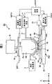
图1是表示作为本发明的曝光装置的器件制造系统的一实施方式的概略构成图。FIG. 1 is a schematic configuration diagram showing an embodiment of a device manufacturing system as an exposure apparatus of the present invention.
图2是从上方观看图1的图。FIG. 2 is a view of FIG. 1 viewed from above.
图3是表示进行曝光处理的曝光装置本体的一实施方式的概略构成图。FIG. 3 is a schematic configuration diagram showing an embodiment of an exposure apparatus body that performs exposure processing.
图4是表示供给喷嘴及回收喷嘴的配置例的图。Fig. 4 is a diagram showing an arrangement example of supply nozzles and recovery nozzles.
图5是表示与本发明相关的液体除去装置的一实施方式的概略构成图。Fig. 5 is a schematic configuration diagram showing an embodiment of a liquid removal device according to the present invention.
图6是表示与本发明相关的液体除去装置的其他实施方式的概略构成图。Fig. 6 is a schematic configuration diagram showing another embodiment of the liquid removal device according to the present invention.
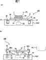
图7(a)及(b)是表示与本发明相关的液体除去装置的其他实施方式的概略构成图。7( a ) and ( b ) are schematic configuration diagrams showing other embodiments of the liquid removal device according to the present invention.
图8是表示与本发明相关的液体除去装置的其他实施方式的概略构成图。Fig. 8 is a schematic configuration diagram showing another embodiment of the liquid removal device according to the present invention.
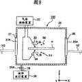
图9是表示与本发明相关的液体除去装置的其他实施方式的概略构成图。Fig. 9 is a schematic configuration diagram showing another embodiment of the liquid removal device according to the present invention.
图10是表示与本发明相关的液体除去装置的其他实施方式的概略构成图。Fig. 10 is a schematic configuration diagram showing another embodiment of the liquid removal device according to the present invention.
图11是表示与本发明相关的液体除去装置的其他实施方式的概略构成图。Fig. 11 is a schematic configuration diagram showing another embodiment of the liquid removal device according to the present invention.
图12是表示与本发明相关的液体除去装置的其他实施方式的概略构成图。Fig. 12 is a schematic configuration diagram showing another embodiment of the liquid removal device according to the present invention.
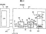
图13是表示作为本发明的曝光装置的器件制造系统的其他实施方式的概略构成图。13 is a schematic configuration diagram showing another embodiment of a device manufacturing system as an exposure apparatus of the present invention.
图14是表示作为本发明的曝光装置的器件制造系统的其他实施方式的概略构成图。14 is a schematic configuration diagram showing another embodiment of a device manufacturing system as an exposure apparatus of the present invention.
图15是表示半导体器件的制造工序阿一例的流程图。FIG. 15 is a flowchart showing an example of a manufacturing process of a semiconductor device.
具体实施方式Detailed ways
第1实施方式first embodiment
下面,一边参照附图一边就本发明的曝光装置及器件制造方法进行说明。图1是表示具有本发明的曝光装置的器件制造系统的一实施方式的图、从侧方观看的概略构成图,图2是从上方观看图1的图。Next, the exposure apparatus and device manufacturing method of the present invention will be described with reference to the drawings. FIG. 1 is a diagram showing one embodiment of a device manufacturing system including an exposure apparatus of the present invention, and a schematic configuration diagram viewed from the side, and FIG. 2 is a diagram viewed from above in FIG. 1 .
在图1、图2中,器件制造系统SYS具有曝光装置EX-SYS、涂敷器·显影器装置C/D-SYS。曝光装置EX-SYS具有:形成与涂敷器·显影器装置C/D-SYS的连接部的接口部IF,将投影光学系统PL与基片P之间用液体50进行充满、经由投影光学系统PL和液体50将图案像投影到基片P上并对基片P进行曝光的曝光装置本体EX,在接口部IF与曝光装置本体EX之间搬送基片P的搬送系统H,设置于搬送系统H的搬送路径的途中、除去附着于曝光处理后的基片P的液体的液体除去装置100,和统括控制曝光装置EX-SYS全体动作的控制装置CONT。涂敷器·显影器装置C/D-SYS具有:对进行曝光处理之前的基片P的基材涂敷光致抗蚀剂(感光剂)的涂敷装置C,和对在曝光装置本体EX中经过曝光处理后的基片P进行显影处理的显影装置(处理装置)D。曝光装置本体EX被配置在对清洁度进行了管理的第1腔室装置CH1内部。另一方面,涂敷装置C及显影装置D被配置在与第1腔室装置CH1不同的第2腔室装置CH2内部。然后,收容曝光装置本体EX的第1腔室装置CH1与收容涂敷装置C及显影装置D的第2腔室装置CH2经由接口部IF连接起来。这里,在以下的说明中,将收容在第2腔室装置CH2内部的涂敷装置C及显影装置D合起来适宜称之为「涂敷器·显影器本体C/D」。In FIGS. 1 and 2 , the device manufacturing system SYS has an exposure device EX-SYS and a coater/developer device C/D-SYS. The exposure device EX-SYS has: an interface part IF forming a connection part with the applicator-developer device C/D-SYS, and the space between the projection optical system PL and the substrate P is filled with
如图1所示,曝光装置本体EX具有:用曝光光EL对掩模台MST所支承的掩模M进行照明的照明光学系统IL,将用曝光光EL照明后的掩模M的图案像投影到基片P上的投影光学系统PL,以及支承基片P的基片台PST。本实施方式中的曝光装置本体EX采用具有2个基片台PST1、PST2的所谓双工作台系统。作为双工作台系统的具体构成,在日本专利公开特开平10-163099号公报、日本专利公开特开平10-214783号公报、特表2000-505958号公报、美国专利6,341,007号、6,400,441号、6,549,269号以及6,590,634号等文献中进行了公开,可参照这些文献。在本国际申请所指定或选定的国家的法令中所允许的范围内,援引这些美国专利并作为本文记载的一部分。在本发明中,能够采用上述文献中所公开的双工作台系统。另外,本实施方式中的曝光装置本体EX为一边将掩模M与基片P朝扫描方向上的相互不同的方向(逆方向)同步移动一边将掩模M上所形成的图案在基片P上进行曝光的扫描型曝光装置(所谓扫描逐次移动式曝光装置)。在以下的说明中,设在水平面内掩模M与基片P的同步移动方向(扫描方向)为X轴方向,设在水平面内与X轴方向正交的方向为Y轴方向(非扫描方向)、设垂直于X轴及Y轴方向与投影光学系统PL的光轴AX一致的方向为Z轴方向。另外,将绕X轴、Y轴及Z轴的方向分别设为θX、θY及θZ方向。此外,这里所说的「基片」包含在半导体晶片上涂敷了抗蚀剂的情况,「掩模」包含在基片上形成经过缩小投影的设备图案的网线(reticle)。As shown in FIG. 1 , the exposure apparatus body EX has an illumination optical system IL for illuminating the mask M supported by the mask stage MST with the exposure light EL, and projects a pattern image of the mask M illuminated with the exposure light EL. A projection optical system PL onto the substrate P, and a substrate stage PST supporting the substrate P. The exposure apparatus main body EX in this embodiment employs a so-called double-stage system having two substrate stages PST1 and PST2. As a specific configuration of the double-table system, there are Japanese Patent Laid-Open No. 10-163099, Japanese Patent Laid-Open No. 10-214783, Japanese Patent Application No. 2000-505958, U.S. Patent Nos. 6,341,007, 6,400,441, and 6,549,269. and No. 6,590,634 and other documents are disclosed, and these documents can be referred to. To the extent permitted by the statutes of the countries designated or selected in this international application, these United States patents are incorporated by reference and are incorporated herein. In the present invention, the double stage system disclosed in the above-mentioned documents can be employed. In addition, the exposure apparatus main body EX in this embodiment transfers the pattern formed on the mask M on the substrate P while synchronously moving the mask M and the substrate P in different directions (reverse directions) in the scanning direction. A scanning exposure device (so-called scanning sequential exposure device) for exposure on top. In the following description, the synchronous movement direction (scanning direction) of the mask M and the substrate P in the horizontal plane is defined as the X-axis direction, and the direction perpendicular to the X-axis direction in the horizontal plane is defined as the Y-axis direction (non-scanning direction). ), let the direction perpendicular to the X-axis and Y-axis directions coincide with the optical axis AX of the projection optical system PL be the Z-axis direction. In addition, the directions around the X axis, the Y axis, and the Z axis are respectively referred to as θX, θY, and θZ directions. In addition, the "substrate" mentioned here includes the case where a resist is coated on the semiconductor wafer, and the "mask" includes a reticle for forming a reduced projected device pattern on the substrate.
搬送系统H具有:将进行曝光处理之前的基片P搬入(装载)基片台PST的第1搬送装置H1,将经过曝光处理后的基片P从基片台PST搬出(卸载)、搬送至液体除去装置100的第2搬送装置H2,和在液体除去装置100与接口部IF之间搬送基片P的第3搬送装置H3。第1、第2、第3搬送装置H1、H2、H3设置在第1腔室装置CH1内部。用涂敷器·显影器本体C/D(涂敷装置C)实施了光致抗蚀剂的涂敫处理的基片P经由接口部IF送给第3搬送装置H3。这里,在与第1、第2腔室装置CH1、CH2各自的接口部IF对面的部分设置有开口部及使该开口部进行开闭的挡板。在基片P的对于接口部IF的搬送动作中,挡板被开放。第3搬送装置H3经由液体除去装置100将进行曝光处理之前的基片P送给第1搬送装置H1。此外,在将基片P从第3搬送装置H3送给第1搬送装置H1之际,也可以不经由液体除去装置100而是经由未图示的其他搬送装置或中继装置送给第1搬送装置H1。第1搬送装置H1将所送来的基片P装载到曝光装置本体EX的基片台PST。经过曝光处理后的基片P由第2搬送装置H2从基片台PST卸载。第2搬送装置H2经由液体除去装置100将卸载后的基片P送给第3搬送装置H3。用第3搬送装置H3所搬送的基片P经由接口部IF搬运到涂敷器·显影器本体C/D(显影装置D)。显影装置D对所送来的基片P实施显影处理。The transfer system H includes: a first transfer device H1 for carrying (loading) the substrate P before exposure processing into the substrate stage PST; The second transfer device H2 of the
此外,由于区分使用将进行曝光处理前的未浸湿的基片P搬入基片台PST的第1搬送装置H1和将经过曝光处理后的有浸湿的可能性的基片P从基片台PST搬出的第2搬送装置H2,所以能够防止液体附着到用第1搬送装置H1所搬送的基片P的背面等,而不会在第1搬送装置(搬送部件)H1上附着液体。In addition, since the first transfer device H1 for carrying the non-wetted substrate P before the exposure treatment into the substrate stage PST and the substrate P that has the possibility of being wetted after the exposure treatment are used from the substrate stage The second conveying device H2 carried out by the PST can prevent the liquid from adhering to the back surface of the substrate P conveyed by the first conveying device H1, without adhering the liquid to the first conveying device (transporting member) H1.
图3是曝光装置本体EX的概略构成图。照明光学系统IL用曝光光EL对掩模台MST所支承的掩模M进行照明,具有曝光用光源、使从曝光用光源射出的光束的照度均一化的光学集成器、对来自光学集成器的曝光光EL进行聚光的聚光镜、中继透镜系统、将利用曝光光EL的掩模M上的照明区域设定成狭缝状的可变视场光圈等。掩模M上的规定照明区域由照明光学系统IL用均一的照度分布的曝光光EL进行照明。作为从照明光学系统IL射出的曝光光EL,例如使用从水银灯射出的紫外区的辉线(g线、h线、i线)及KrF激态复合物激射光(波长248nm)等远紫外光(DUV光),或ArF激态复合物激射光(波长193nm)及F2激射光(波长157nm)等真空紫外光(VUV光)等。在本实施方式中,使用ArF激态复合物激射光。FIG. 3 is a schematic configuration diagram of an exposure apparatus body EX. The illumination optical system IL illuminates the mask M supported by the mask stage MST with the exposure light EL, and includes an exposure light source, an optical integrator for uniforming the illuminance of the light beam emitted from the exposure light source, and an optical integrator for A condenser lens for condensing the exposure light EL, a relay lens system, a variable field diaphragm for setting an illumination area on the mask M using the exposure light EL in a slit shape, and the like. The predetermined illumination area on the mask M is illuminated with the exposure light EL of uniform illuminance distribution by the illumination optical system IL. As the exposure light EL emitted from the illumination optical system IL, for example, ultraviolet rays (g-ray, h-ray, i-ray) emitted from a mercury lamp and far-ultraviolet light (wavelength 248 nm) such as KrF exciplex laser light (wavelength 248 nm) are used. DUV light), or vacuum ultraviolet light (VUV light) such as ArF exciplex laser light (wavelength 193nm) and F2 laser light (wavelength 157nm), etc. In the present embodiment, ArF exciplex lasing light is used.
掩模台MST支撑掩模M,可在垂直于投影光学系统PL的光轴AX的平面内、即XY平面内进行2维移动以及可沿θZ方向进行微小旋转。掩模台MST由线性马达等掩模台驱动装置MSTD进行驱动。掩模台驱动装置MSTD由控制装置CONT进行控制。掩模台MST上的掩模M的2维方向的位置以及旋转角由激光干涉仪实时地进行测量,测量结果被输出到控制装置CONT。控制装置CONT基于激光干涉仪的测量结果对掩模台驱动装置MSTD进行驱动由此来进行掩模台MST所支承的掩模M的定位。Mask stage MST supports mask M, and is capable of two-dimensional movement in a plane perpendicular to optical axis AX of projection optical system PL, that is, XY plane, and fine rotation in the θZ direction. Mask stage MST is driven by a mask stage driving device MSTD such as a linear motor. The mask table driving device MSTD is controlled by the control device CONT. The two-dimensional position and rotation angle of the mask M on the mask stage MST are measured by a laser interferometer in real time, and the measurement results are output to the control device CONT. Control device CONT positions mask M supported by mask stage MST by driving mask stage drive device MSTD based on the measurement result of the laser interferometer.
投影光学系PL将掩模M的图案以规定的投影倍率β在基片P上进行投影曝光,由多个光学元件(透镜)构成,这些光学元件由作为金属部件的镜筒(barrel)PK进行支承。在本实施方式中,投影光学系统PL是投影倍率β为例如1/4或者1/5的缩小系统。此外,投影光学系统PL既可以是等倍系统及扩大系统中的某一个,也可以使用反射镜来构成。另外,在本实施方式的投影光学系统PL的前端侧(基片P侧),光学元件(透镜)60从镜筒PK露出来。该光学元件60相对于镜筒PK可装拆(更换)地进行设置。The projection optical system PL projects the pattern of the mask M onto the substrate P at a predetermined projection magnification β, and is composed of a plurality of optical elements (lenses). support. In the present embodiment, projection optical system PL is a reduction system in which projection magnification β is, for example, 1/4 or 1/5. In addition, projection optical system PL may be any one of a constant magnification system and an enlargement system, or may be configured using mirrors. In addition, on the front end side (substrate P side) of projection optical system PL of this embodiment, optical element (lens) 60 is exposed from lens barrel PK. The
基片台PST支撑基片P,具备经由衬底架保持基片P的Z工作台51,支承Z工作台51的XY工作台52,以及支承XY工作台52的基座53。基片台PST由线性马达等基片台驱动装置PSTD进行驱动。基片台驱动装置PSTD由控制装置CONT进行控制。通过驱动Z工作台51来控制Z工作台51所保持的基片P的Z轴方向上的位置(聚焦位置)以及θX、θY方向上的位置。另外,通过驱动XY工作台52来控制基片P的XY方向上的位置(与投影光学系统PL的像面实质上平行的方向的位置)。即,Z工作台51对基片P的聚焦位置及倾斜角进行控制以自动聚焦(auto-focus)方式及自动调整(auto-leveling)方式将基片P的表面合并到投影光学系统PL的像面,XY工作台52进行基片P的X轴方向及Y轴方向上的定位。此外,不言而喻也可以将Z工作台与XY工作台一体地进行设置。The substrate stage PST supports the substrate P, and includes a
在基片台PST(Z工作台51)上设置有移动镜54。另外,在与移动镜54相对的位置设置有激光干涉仪55。基片台PST上的基片P的2维方向的位置及旋转角由激光干涉仪55实时地进行测量,测量结果被输出到控制装置CONT。控制装置CONT基于激光干涉仪55的测量结果对基片台驱动装置PSTD进行驱动由此来进行基片台PST上所支承的基片P的定位。A moving
在本实施方式中,为了将曝光波长实质缩短以改善析像度,同时将聚焦深度实质扩展,而适用浸液法。为此,至少在将掩模M的图案像转印到基片P上的期间,在基片P的表面与投影光学系统PL的基片P侧的光学元件(透镜)60的前端面(下面)7之间充满规定的液体50。如上述那样,构成为在投影光学系统PL的前端侧透镜60露出来,液体50仅与透镜60接触。由此,就能够防止由金属组成的镜筒PK的腐蚀等。在本实施方式中,在液体50上使用纯水。纯水不仅在ArF激态复合物激射光,在将曝光光EL设为例如从水银灯射出的紫外区的辉线(g线、h线、i线)及KrF激态复合物激射光(波长248nm)等远紫外光(DUV光)的情况下也可透过该曝光光EL。In this embodiment, the liquid immersion method is applied in order to substantially shorten the exposure wavelength to improve the resolution and to substantially expand the depth of focus. For this reason, at least during the transfer of the pattern image of the mask M onto the substrate P, there is a gap between the surface of the substrate P and the front end surface (lower surface) of the optical element (lens) 60 on the substrate P side of the projection optical system PL. )7 is filled with the prescribed
曝光装置EX具有对投影光学系统PL的前端面(透镜60的前端面)7与基片P之间的空间56供给规定的液体50的液体供给装置1和回收空间56的液体50的液体回收装置2。液体供给装置1用于将投影光学系统PL与基片P之间的至少一部分用液体50进行充满,具有收容液体50的容器、加压泵等。在液体供给装置1上连接供给管3的一端部,在供给管3的另一端部连接着供给喷嘴4。液体供给装置1经由供给管3及供给喷嘴4对空间56供给液体50。The exposure apparatus EX has a liquid supply device 1 that supplies a
液体回收装置2具有吸入泵、收容所回收的液体50的容器等。在液体回收装置2上连接着回收管6的一端部,在回收管6的另一端部连接着回收喷嘴5。液体回收装置2经由回收喷嘴5及回收管6对空间56的液体50进行回收。在对空间56充满液体50之际,控制装置CONT驱动液体供给装置1,经由供给管3及供给喷嘴4每单位时间对空间56供给规定量的液体50,同时驱动液体回收装置2,经由回收喷嘴5及回收管6每单位时间自空间56回收规定量的液体50。由此,在投影光学系统PL的前端面7与基片P之间的空间56保持着液体50。The liquid recovery device 2 has a suction pump, a container for storing the recovered
投影光学系统PL的最下端透镜60其前端部60A在扫描方向仅剩余必要的部分且在Y轴方向(非扫描方向)细长呈矩形而形成。在扫描曝光时掩模M的一部分图案像被投影到前端面60A正下方的矩形投影区域,相对于投影光学系统PL掩模M在-X方向(或者+X方向)以速度V进行移动,与此相同步经由XY工作台52使基片P在+X方向(或者-X方向)以速度β·V(β是投影倍率)进行移动。然后,在对一个拍摄区域的曝光结束后,通过基片P的步进使下一拍摄区域移动到扫描开始位置,下面,以步进扫描(step-and-scan)方式依次进行对于各拍摄区域的曝光处理。在本实施方式中,平行于基片P的移动方向在与基片的移动方向的同一方向流过液体50这样来进行设定。The
图4是表示投影光学系统PL的透镜60的前端部60A、在X轴方向供给液体50的供给喷嘴4(4A~4C)、以及回收液体50的回收喷嘴5(5A、5B)的位置关系的图。在图4中,透镜60的前端面60A的形状为在Y轴方向细长的矩形,在+X方向侧配置3个供给喷嘴4A~4C,在-X方向侧配置2个回收喷嘴5A、5B以使得在X轴方向夹着投影光学系统PL的透镜60的前端部60A。然后,供给喷嘴4A~4C经由供给管3连接到液体供给装置1,回收喷嘴5A、5B经由回收管4连接到液体回收装置2。另外,在将供给喷嘴4A~4C和回收喷嘴5A、5B相对于前端部60A的中心大致旋转了180°的位置配置着供给喷嘴8A~8C和回收喷嘴9A、9B。供给喷嘴4A~4C与回收喷嘴9A、9B在Y轴方向上交互排列,供给喷嘴8A~8C与回收喷嘴5A、5B在Y轴方向上交互排列,供给喷嘴8A~8C经由供给管10连接到液体供给装置1,回收喷嘴9A、9B经由回收管11连接到液体回收装置2。此外,进行来自喷嘴的液体供给以使得在投影光学系统PL与基片P之间不发生气体部分。4 is a graph showing the positional relationship between the
在曝光装置本体EX中,在朝箭头Xa(参照图4)所示的扫描方向(-X方向)使基片P移动来进行扫描曝光的情况下,使用供给管3、供给喷嘴4A~4C、回收管4以及回收喷嘴5A、5B,借助于液体供给装置1及液体回收装置2来进行液体50的供给及回收。即,在基片P朝-X方向移动之际,经由供给管3及供给喷嘴4(4A~4C)液体50从液体供给装置1被供给到投影光学系统PL与基片P之间,同时经由回收喷嘴5(5A、5B)及回收管6液体50被回收到液体回收装置2,为了充满透镜60与基片P之间液体50在-X方向进行流动。另一方面,在朝箭头Xb所示的扫描方向(+X方向)使基片P移动来进行扫描曝光的情况下,使用供给管10、供给喷嘴8A~8C、回收管11及回收喷嘴9A、9B,借助于液体供给装置1及液体回收装置2来进行液体50的供给以及回收。即,在基片P朝+X方向移动之际,经由供给管10及供给喷嘴8(8A~8C)液体50从液体供给装置1被供给投影光学系统PL与基片P之间,同时经由回收喷嘴9(9A、9B)及回收管11液体50被回收到液体回收装置2,为了充满透镜60与基片P之间液体50在+X方向进行流动。这样,控制装置CONT使用液体供给装置1及液体回收装置2沿基片P的移动方向流过液体50。在该情况下,例如从液体供给装置1经由供给喷嘴4所供给的液体50,由于伴随向基片P的-X方向的移动被引入空间56这样进行流动,所以即便液体供给装置1的供给能量较小也能够将液体50容易地供给空间56。而且,通过依照扫描方向来切换使液体50流动的方向,在沿+X方向或-X方向任一方向扫描基片P的情况下都能够用液体50充满透镜60的前端面7与基片P之间,并能够获得较高的析像度及较广的聚焦深度。In the exposure apparatus body EX, when performing scanning exposure by moving the substrate P in the scanning direction (-X direction) indicated by the arrow Xa (refer to FIG. 4 ), the
接着,一边参照图5一边就第1实施方式的曝光装置中所用的液体除去装置100进行说明。液体除去装置100设置于搬送系统H的搬送路径的途中、将由于浸液法而附着在经过曝光处理后的基片的P液体50除去。在本实施方式中,液体除去装置100被设置于第2搬送装置H2与第3搬送装置H3之间。液体除去装置100具有工作台装置20,设置于工作台装置20、保持基片P的下面中央部的支架部21,和使保持基片P的支架部(holder)21进行旋转的旋转机构22。在支架部21的上面设置着保持真空装置的一部分的真空吸附孔,支架部21吸附保持基片P的下面中央部。旋转机构22由设置于工作台装置20内部的马达构成,通过使连接到支架部21的轴部23旋转来使支架部21进行旋转。而且,工作台装置20、支架部21以及旋转机构22被设置于作为盖壳机构的腔室25内部,在腔室25中经由流路28设置有液体吸引装置(liquid-sucking)29。在流路28上设置有阀28A。Next, the
支架部21与轴部(shaft)23一起相对于工作台装置20的上面可升降地进行设置。在保持基片P的支架部21相对于工作台装置20上升时,基片P自工作台装置20离开,借助于旋转机构22的驱动可进行旋转。另一方面,在支架部21下降时基片P由设置于工作台装置20的上面的第2支架部24进行保持。The
腔室25具有形成于第2搬送装置H2侧的第1开口部26和形成于第3搬送装置H3侧的第2开口部27。在第1开口部26上设置有使该第1开口部26进行开闭的第1挡板26A,在第2开口部27上设置有使该第2开口部27进行开闭的第2挡板27A。第1、第2挡板26A、27A的开闭动作由控制装置CONT进行控制。若第1挡板26A被开放则第2搬送装置H2可经由第1开口部26访问液体除去装置100的工作台装置20。即,第2搬送装置H2可经由第1开口部26将基片P对液体除去装置100的工作台装置20进行搬送(搬入)。第3搬送装置H3经由第2开口部27可访问液体除去装置100的工作台装置20。即,第3搬送装置H3可经由第2开口部27将基片P对液体除去装置100的工作台装置20进行搬送(搬出)。另一方面,通过将第1、第2挡板26A、27A关闭使腔室25内部密封起来。The
接着,利用图1及图2就具备上述的曝光装置本体EX及液体除去装置100的器件制造系统SYS的动作进行说明。Next, the operation of the device manufacturing system SYS including the above-mentioned exposure apparatus main body EX and the
在曝光装置本体EX中,基片台PST1上所保持的基片P利用浸液法进行曝光,与其并行对基片台PST2上所保持的基片P,进行对准标记的检测或表面信息(AF(自动聚焦)/AL(自动调整)信息)的测量。图1表示基片台PST1在曝光装置本体(曝光位置)EX中进行曝光动作,基片台PST2在测量位置上进行测量动作的情形。在曝光装置本体中,进行液体供给装置1的液体供给与液体回收装置2的液体回收,投影光学系统PL的像面侧的曝光光的光路用液体50充满。若基片台PST1上所保持的基片P的曝光处理完成,则停止液体供给装置1的液体供给,由液体回收装置2进行液体回收。若利用液体回收装置2的液体回收结束,则基片台PST1从曝光装置本体EX进行退避,同时已结束各种测量的基片台PST2被放入曝光装置本体(曝光位置)EX。在基片台PST1上结束了曝光处理的基片P借助于基片台PST1被装载到第2搬送装置H2。结束了曝光处理后的基片P卸载的基片台PST1从第1搬送装置H1接受未曝光的基片P,开始测量位置上的各种测量。在第2搬送装置H2所卸载的基片P上稍微附着有未被液体回收装置2所回收完了的液体50,由第2搬送装置H2搬送到液体除去装置100。这样,并列进行基片台PST2所保持的基片P的曝光处理以及基片台PST1所保持的未曝光的基片P的各种测量,并用液体除去装置100进行在紧前面结束了曝光处理的基片P上所残留的液体的除去。In the exposure device body EX, the substrate P held on the substrate stage PST1 is exposed by the immersion method, and in parallel with it, the detection of the alignment mark or the surface information ( AF (Auto Focus)/AL (Auto Adjustment) information). FIG. 1 shows a state where the substrate stage PST1 performs an exposure operation in the exposure apparatus body (exposure position) EX, and the substrate stage PST2 performs a measurement operation in a measurement position. In the exposure apparatus main body, the liquid supply by the liquid supply device 1 and the liquid recovery by the liquid recovery device 2 are performed, and the optical path of the exposure light on the image plane side of the projection optical system PL is filled with the liquid 50 . When the exposure processing of the substrate P held on the substrate stage PST1 is completed, the liquid supply from the liquid supply device 1 is stopped, and the liquid recovery device 2 recovers the liquid. When the liquid recovery by the liquid recovery device 2 is completed, the substrate stage PST1 is retracted from the exposure apparatus body EX, and the substrate stage PST2 having completed various measurements is put into the exposure apparatus body (exposure position) EX. The substrate P whose exposure processing has been completed on the substrate stage PST1 is loaded onto the second transport device H2 via the substrate stage PST1. The substrate stage PST1 on which the substrate P after the exposure process has been unloaded receives the unexposed substrate P from the first transport device H1, and starts various measurements at the measurement position. The liquid 50 that has not been recovered by the liquid recovery device 2 slightly adheres to the substrate P unloaded by the second transport device H2, and is transported to the
此外,在对基片台PST2所保持的基片P上从液体供给装置1开始供给液体之际,在基片台PST1不进行实质的测量动作,而是仅进行基片台PST1的移动,或者单单使基片台PST1停止为好。通过这样进行处理,就能够防止在基片台PST2上从液体供给装置1开始液体供给之际所产生的振动对测量位置中的基片台PST1的测量动作带来影响。另外,当在停止向基片台PST2上供给液体时,测量位置上的基片台PST1的测量动作尚未结束的情况下,也可以在停止液体供给时,在基片台PST1不进行实质的测量动作,而是仅仅进行基片台PST1的移动,或者单单使基片台PST1停止。In addition, when the supply of liquid from the liquid supply device 1 to the substrate P held by the substrate stage PST2 is started, the substrate stage PST1 does not perform a substantial measurement operation, but only the movement of the substrate stage PST1 is performed, or It is better to simply stop the substrate stage PST1. By doing so, it is possible to prevent the vibration generated when the liquid supply from the liquid supply device 1 on the substrate stage PST2 is started from affecting the measurement operation of the substrate stage PST1 at the measurement position. In addition, when the measurement operation of the substrate stage PST1 at the measurement position has not been completed when the liquid supply to the substrate stage PST2 is stopped, the actual measurement may not be performed on the substrate stage PST1 when the liquid supply is stopped. Instead, only the movement of the substrate stage PST1 is performed, or only the substrate stage PST1 is stopped.
控制装置CONT伴随着对第2搬送装置H2的液体除去装置100的接近将第1挡板26A开放(参照图5)。此时,第2挡板27A关闭。第2搬送装置H2经由第1开口部26将基片P送给液体除去装置100的工作台装置20。此时,支架部21下降,基片P被保持于工作台装置20上的支架部21及第2支架部24。The control device CONT opens the
一旦将基片P送到工作台装置20,第2搬送装置H2就经由第1开口部26自腔室25退避。如果第2搬送装置H2自腔室25进行退避则控制装置CONT关闭第1挡板26A。由此,腔室25内部被密封。如果腔室25内部被密封,则控制装置CONT将支架部21上升。在支架部21上升的同时,吸附保持于该支架部21的基片P也相对于工作台装置20进行上升。然后,控制装置CONT驱动旋转机构22,使支架部21与基片P一起朝θZ方向进行旋转。通过旋转机构22使基片P旋转,附着在基片P的上下两面的液体50就借助于离心力的作用从基片P飞散。由此,附着在基片P的液体50就从基片P除去。这里,由于基片P被配置在作为盖壳机构的腔室25内部,所以从基片P飞散的液体5不会飞溅在周围。Once the substrate P is sent to the
从基片P飞散的液体50由连接到腔室25的液体吸引装置29进行回收。液体吸引装置29通过将腔室25内部的气体与飞溅的液体50一起吸引来回收从基片P飞散的液体50。这里,液体吸引装置29继续进行腔室25内部的气体及飞溅的液体50的吸引动作。据此,由于液体50不会存留在腔室25的内壁或底等腔室25内部,所以腔室25内部的湿度不会变动太大。另外,即使在开放挡板26A、27A时,腔室25内潮湿的气体也不会流出到腔室25外。The liquid 50 scattered from the substrate P is recovered by the
一旦基片P旋转了规定时间(或者规定旋转数),控制装置CONT就停止旋转机构22的驱动,将基片P与支架部21一起下降。接着,控制装置CONT开放第2挡板27A。一旦第2挡板27A被开放,第3搬送装置(第2搬送部件)H3就经由第2开口部27访问工作台装置20,保持工作台装置20上的液体50被除去的基片P。保持由液体除去装置100除去了液体50的基片P的第3搬送装置H3,自腔室25内部经由第2开口部27将基片P搬出。When the substrate P has rotated for a predetermined time (or a predetermined number of rotations), the control device CONT stops the driving of the
如图1所示,借助于液体除去装置100除去了液体50的基片P,经由接口部IF被运到涂敷器·显影器本体C/D。涂敷器·显影器本体C/D(显影装置D)对所送来的基片P实施显影处理。这样,在本实施方式的曝光装置EX-SYS经由接口部IF将基片P搬出到涂敷器·显影器装置CD-SYS之前,借助于液体除去装置100除去附着于基片P的液体50。As shown in FIG. 1, the substrate P from which the liquid 50 has been removed by the liquid removing
如以上说明那样,由于将在曝光装置本体EX中实施了曝光处理的基片P搬送到涂敷器·显影器装置C/D-SYS(显影装置D)之前,用液体除去装置100除去附着于基片P的液体50,所以能够消除液体50对于显影处理的影响。另外,通过由液体除去装置100除去附着于基片P的液体50,就能够防止在基片P的搬送中液体从基片P落下、造成第1腔室装置CH1内部的湿度变化(环境变化),或者使搬送路径上的各装置或部件生锈等的良情形的发生。As described above, since the substrate P subjected to exposure processing in the exposure apparatus body EX is transported to the coater/developer apparatus C/D-SYS (developer D), the
另外,由于将附着有液体50的基片P用第2搬送装置H2进行搬送,将除去了液体50的基片P用与第2搬送装置H2不同的第3搬送装置H3进行搬送,所以第3搬送装置H3不会被液体50淋到。从而,在第3搬送装置H3所搬送的基片P上不会附着液体50,另外,能够可靠地防止第3搬送装置H3的搬送路径上的液体50的飞溅。In addition, since the substrate P with the liquid 50 attached is conveyed by the second conveying device H2, and the substrate P from which the liquid 50 has been removed is conveyed by the third conveying device H3 different from the second conveying device H2, so the third The conveying device H3 is not drenched by the liquid 50 . Accordingly, the liquid 50 does not adhere to the substrate P conveyed by the third conveyance device H3, and splashing of the liquid 50 on the conveyance path of the third conveyance device H3 can be reliably prevented.
另外,由于将液体除去装置100设置于搬送系统H的搬送路径的途中,所以能够同时进行利用曝光装置本体EX的曝光处理和利用液体除去装置100的液体除去处理。从而,能够不使生产能力降低地执行各处理。而且,由于是在腔室25内部进行液体除去处理,所以能够防止液体50飞溅到周围。In addition, since the
此外,虽然在本实施方式中,在将曝光处理后的基片P搬送到作为处理装置的涂敷器·显影器装置C/D-SYS之际,经由作为连接部的接口部IF进行搬送如此进行了说明,但例如在涂敷器·显影器装置C/D-SYS中具备接口部IF的情况下、或者在涂敷器·显影器装置C/D-SYS不经由接口部IF直接连接到曝光装置EX-SYS的情况下,或者,处理装置为基片收纳装置且不经由接口部IF将曝光处理后的基片P搬送到基片收纳装置的情况下,第1腔室装置CH1的开口部就成为曝光装置EX-SYS的连接部。In addition, although in this embodiment, when the substrate P after exposure processing is conveyed to the coater-developer apparatus C/D-SYS as a processing apparatus, it conveys through the interface part IF which is a connection part. Although the description has been made, for example, when the applicator/developer unit C/D-SYS is equipped with an interface unit IF, or when the applicator-developer unit C/D-SYS is directly connected to the In the case of the exposure device EX-SYS, or when the processing device is a substrate storage device and the exposed substrate P is transported to the substrate storage device without the interface part IF, the opening of the first chamber device CH1 The part becomes the connection part of the exposure device EX-SYS.
如上述那样,本实施方式中的液体50由纯水构成。纯水在半导体制造工厂等能够容易地大量获得,同时还具有没有对于基片P上的光致抗蚀剂(光刻胶)或光学元件(透镜)等的不好影响的优点。另外,纯水没有对于环境的不好影响,同时不纯物的含有量极其低,所以还能够期待对基片P的表面以及设置于投影光学系统PL的前端面的光学元件的表面进行洗净的作用。As mentioned above, the liquid 50 in this embodiment consists of pure water. Pure water can be easily obtained in large quantities in semiconductor manufacturing factories and the like, and has the advantage of not having adverse effects on photoresist (photoresist) or optical elements (lens) on the substrate P or the like. In addition, pure water has no bad influence on the environment, and at the same time, the content of impurities is extremely low, so it can also be expected to clean the surface of the substrate P and the surface of the optical element provided on the front end surface of the projection optical system PL. role.
而且,纯水(水)相对于波长为193nm程度的曝光光EL的折射率n被认为在1.44~1.47左右,在利用ArF激态复合物激射光(波长193nm)作为曝光光EL的光源的情况下,在基片P上以1/n、即约131~134nm程度被短波长化而得到较高的析像度。进而,聚焦深度与空气中相比以约n倍、即约1.44~1.47倍程度被扩大,所以在能够确保与在空气中使用的情况同程度的聚焦深度即可的情况下,就能够使投影光学系统PL的数值口径进一步增加,在这一点上析像度也将改善。Furthermore, the refractive index n of pure water (water) with respect to the exposure light EL having a wavelength of about 193 nm is considered to be about 1.44 to 1.47. Next, on the substrate P, the wavelength is shortened by 1/n, that is, about 131 to 134 nm, to obtain a higher resolution. Furthermore, the depth of focus is enlarged by about n times, that is, about 1.44 to 1.47 times compared with that in the air. Therefore, it is possible to make the projection The numerical aperture of the optical system PL is further increased, and the resolution will also be improved at this point.
虽然在本实施方式中,在投影光学系统PL的前端安装了透镜60,但作为安装于投影光学系统PL的前端的光学元件,还可以是在投影光学系统PL的光学特性、例如像差(球面像差、彗形像差等)的调整中所用的光学片。或者也可以是可透过曝光光EL的平行平面板。通过将与液体50接触的光学元件设为比透镜廉价的平行平面板,即使在曝光装置EX的搬运、组装、调整时等将使投影光学系统PL的透射系数、基片P上的曝光光EL的照度以及照度分布的均一性降低的物质(例如硅族有机物等)附着于该平行平面板,仅在供给液体50之前更换该平行平面板即可,具有比将与液体50接触的光学元件设为透镜的情况其更换成本低之类的优点。即,由于因曝光光EL的照射而从抗蚀剂发生的飞溅粒子、或起因于液体50中的不纯物的附着等而弄脏与液体50接触的光学元件的表面,所以需要定期地更换该光学元件,通过将该光学元件设为廉价的平行平面板,与透镜相比就能够使更换部件的成本变低,且能够使更换所要的时间变短,还能够抑制维修成本(运转成本)的上升或生产能力的低下。Although in this embodiment, the
此外,在因液体50的流动所产生的投影光学系统PL的前端的光学元件与基片P之间的压力较大的情况下,还可以不是可更换该光学元件而是牢固地固定光学元件以使其不会因该压力而活动。In addition, when the pressure between the optical element at the front end of the projection optical system PL and the substrate P due to the flow of the liquid 50 is large, the optical element may be firmly fixed instead of being replaced. so that it does not act on that stress.
此外,虽然在本实施方式中,是在投影光学系统PL与基片P表面之间用液体50充满的构成,但也可以是例如在基片P的表面上安装由平行平面板组成的玻璃盖片的状态下充满液体50的构成。In addition, although in the present embodiment, the liquid 50 is filled between the projection optical system PL and the surface of the substrate P, for example, a cover glass composed of a parallel plane plate may be attached to the surface of the substrate P. The sheet state is filled with
此外,在上述各实施方式中,上述喷嘴的形状并不特别进行限定,例如对于前端部60A的长边也可以用两对喷嘴进行液体50的供给或者回收。此外,由于在此情况下从+X方向或-X方向的任一方向均能够进行液体50的供给及回收,所以也可以在上下并列配置供给喷嘴和回收喷嘴。In addition, in each of the above-mentioned embodiments, the shape of the nozzle is not particularly limited, and for example, two pairs of nozzles may be used to supply or recover the liquid 50 on the long side of the
第2实施方式2nd embodiment
接着,一边参照图6一边就本发明的第2实施方式的曝光装置中所用的液体除去装置100进行说明。这里,在下面的说明中,关于液体除去装置100以外,由于与第1实施方式相同或等同故简略或者省略其说明。Next, the
在图6中,液体除去装置100,为了在进行附着于基片P的液体50的除去时不使液体50飞溅,而具备构成覆盖基片P周围的盖壳机构的一部分的盖壳部(cover)30。本实施方式中的液体除去装置100不具有腔室25。盖壳部30平面看大致呈圆环状形成,在该圆环内部具有凹槽(pocket)部30A。在盖壳部30的凹槽部30A中连接着液体吸引装置29。另外,盖壳部30可配置在形成于工作台装置20的凹部31,借助于升降机构32可相对于工作台装置20升降地(可出没地)进行设置。在进行液体除去处理之际,在支架部21上升的同时盖壳部30也上升。由于盖壳部30被设置成覆盖基片P的周围,所以因基片P的旋转而飞散的液体50被回收到盖壳部30的凹槽部30A。被回收到凹槽部30A的液体50由液体吸引装置29进行回收。In FIG. 6, the
如以上说明那样,作为盖壳机构还能够使用覆盖基片P的周围的盖壳部30。由此,与第1实施方式中说明过的腔室25相比能够以简易的构成防止液体50向周围飞溅。As described above, the
第3实施方式third embodiment
接着,一边参照图7一边就第3实施方式的曝光装置中所用的液体除去装置100进行说明。本实施方式的特征部分为构成液体除去装置100的旋转机构22及盖壳部30设置于进行曝光处理的曝光装置本体EX的基片台PST这一点。由于曝光装置本体EX的构造与第1实施方式相同所以省略其说明。Next, the
在图7(a)中,基片台PST具有保持基片P的支架部21及第2支架部24和可收容盖壳部30的凹部31。然后,如图7(a)所示,对支架部21及第2支架部24上所保持的基片P经由投影光学系统PL及液体50转印图案像。一旦对于基片P的曝光处理结束,控制装置CONT,如图7(b)所示,停止对于投影光学系统PL与基片P之间的从液体供给装置1的液体50的供给,同时借助于液体回收装置2回收基片P上的液体50。若该回收作业结束,则使基片台PST从投影光学系统PL的正下方退避。接着,控制装置CONT在使保持基片P的支架部21上升的同时将盖壳部30上升,驱动旋转机构22使基片P进行旋转。由此,用液体回收装置2未回收完了而附着于基片P的液体50就从基片P被除去。然后,一旦将附着在基片P的液体50除去,第2搬送装置H2就自基片台PST将基片P搬出。In FIG. 7( a ), the substrate stage PST has a
如以上说明那样,还可以将液体除去装置100设置于基片台PST。而且,通过在将基片P从进行曝光处理的基片台PST搬出之前,除去附着于基片P的液体,就能够防止在基片P的搬送中液体50从基片P落下之类的不良情形的发生。另外,在本实施方式中,由于曝光装置本体EX采用双工作台系统,所以能够同时进行第1基片台PST1中的曝光处理和第2基片台PST2中的液体除去处理,并能够不使生产能力降低地执行全体处理。As described above, the
另外,虽然在第3实施方式中,为了在将曝光处理后的基片P从基片台PST搬送之前除去附着于基片P的液体而采用使基片P旋转的机构,但既可以设置吹掉液体的吹风机(blower)、或者与液体回收装置2不同另行设置对基片P上的残留液体进行吸引的机构,也可以并用它们。In addition, although in the third embodiment, the mechanism for rotating the substrate P is used to remove the liquid adhering to the substrate P before the exposed substrate P is transferred from the substrate stage PST, a blower may be provided. A blower for removing liquid, or a mechanism for sucking liquid remaining on the substrate P separately from the liquid recovery device 2 may be used in combination.
第4实施方式4th embodiment
接着,一边参照图8一边就第4实施方式的曝光装置中所用的液体除去装置100进行说明。图8所示的液体除去装置100为设置于搬送系统H的搬送路径的途中,即第2搬送装置H2与第3搬送装置H3之间、具备腔室25的构成。由于曝光装置本体EX的构造与第1实施方式相同所以省略其说明。Next, the
在图8中,液体除去装置100具备:通过对基片P的表面(上面)吹喷气体使附着于该基片P的表面的液体50飞散来进行除去的第1吹刮部(blow section)33,和通过对基片P的背面(下面)吹喷气体使附着于该基片P的背面的液体50飞散来进行除去的第2吹刮部34。第1、第2吹刮部33、34分别经由流路连接到气体供给装置35。在流路上设置有将对基片P吹喷的气体中的异物(灰尘或油雾)除去的过滤器。而且,气体供给装置35将经过干燥的气体供给第1、第2吹刮部33、34。在本实施方式中,气体供给装置35供给干燥空气。In FIG. 8 , the
图9是从上方观看图8的腔室25内部的图。如图9所示,基片P其下面的Y轴方向两端部由保持装置36进行保持(此外,在图8中保持装置36未被图示)。保持装置36通过第2搬送装置H2传送基片P、并保持所传送的基片P。另外,保持装置36上所保持的基片P被传给第3搬送装置H3。第1吹刮部33具备设Y轴方向为长度方向的喷嘴本体部33A、和在喷嘴本体部33A的长度方向排列多个而设置的喷嘴孔33B。从气体供给装置35供给的干燥空气从多个喷嘴孔33B分别吹出。第2吹刮部34也具有与第1吹刮部33等同的构成,具有设Y轴方向为长度方向的喷嘴本体部和多个喷嘴孔。FIG. 9 is a view of the inside of the
保持装置36上所保持的基片P与第1、第2吹刮部33、34可相对移动地进行设置。在本实施方式中,第1、第2吹刮部33、34对保持装置36上所保持的基片P在X轴方向上进行扫描移动。此外,既可以在保持装置36上设置驱动装置,使基片P相对于第1、第2吹刮部33、34进行移动,也可以使第1、第2吹刮部33、34和保持装置36两者进行移动。The substrate P held by the holding
接着,就具有上述构成的液体除去装置100的动作进行说明。第2搬送装置H2将附着有液体50的基片P送给保持装置36。控制装置CONT利用第1、第2吹刮部33、34对保持装置36所保持着的基片P吹喷气体。这里,由第1、第2吹刮部33、34所吹喷的气体相对于基片P的表面及背面从倾斜方向进行吹喷。控制装置CONT一边使第1、第2吹刮部33、34在X轴方向相对于保持装置36所保持的基片P进行移动一边吹喷气体。这里,由于第1、第2吹刮部33、34各自的喷嘴本体部的长度远远大于基片P,所以没有遗漏地对基片P的表背面全体吹喷气体。通过吹喷气体使附着在基片P的液体50飞散、除去。分散的液体50被回收到液体吸引装置29。除去了液体50的基片P被传送到第3搬送装置H3。Next, the operation of the
第5实施方式fifth embodiment
接着,一边参照图10一边就第5实施方式的曝光装置中所用的液体除去装置100进行说明。在图10中,液体除去装置100具备:经由流路连接到液体吸引装置29、对分别附着于基片P的表面及背面的液体50进行吸引的第1、第2吸引部37、38,和对腔室25内部进行干燥的干燥装置39。第1、第2吸引部37、38相对于基片P在X轴方向可相对移动地进行设置。在除去附着在基片P的液体50之际,控制装置CONT在使第1、第2吸引部37、38接近到基片P的状态下,驱动液体吸引装置29。由此,附着在基片P的液体50经由第1、第2吸引部37、38被吸引到液体吸引装置29。然后,一边使第1、第2吸引部37、38相对于基片P在X轴方向进行移动一边进行利用液体吸引装置29的吸引动作,由此除去附着在基片P的液体50。此时,干燥装置39对腔室25内部供给经过干燥的气体(干燥空气)。借助于干燥装置39的驱动使腔室25内部进行干燥,由此就能够促进液体50从基片P除去。由于曝光装置本体EX的构造与第1实施方式相同所以省略其说明。Next, a
此外,也可以同时执行利用图10所说明过的、吸引基片P上的液体50的吸引(sucking)动作,和利用图8所说明过的、自吹刮部的气体吹刮(gas-blowing)动作。或者,也可以在执行吸引动作及气体吹刮动作中的某一个后,执行另一个。另外,还能够并列进行利用干燥装置39的干燥动作,也能够在吸引动作或气体吹刮动作的前后进行干燥动作。即,能够使吸引动作、干燥动作以及气体吹刮动作(液体吹掉动作)适宜组合起来执行。In addition, the suction (sucking) operation for sucking the liquid 50 on the substrate P as described in FIG. 10 and the gas-blowing operation from the blowing part as described in FIG. 8 may also be performed simultaneously. )action. Alternatively, after one of the suction operation and the gas blowing operation is performed, the other may be performed. In addition, the drying operation by the drying device 39 can also be performed in parallel, and the drying operation can also be performed before and after the suction operation or the gas blowing operation. That is, it is possible to perform the suction operation, the drying operation, and the gas blowing operation (liquid blowing operation) in an appropriate combination.
第6实施方式sixth embodiment
接着,一边参照图11一边就第6实施方式的曝光装置的液体除去装置100进行说明。此外,由于曝光装置本体EX的构造与第1实施方式相同所以省略其说明。在图11中,液体除去装置100具备:第1、第2吹刮部33、34和收容该第1、第2吹刮部33、34的腔室40。本实施方式中的腔室40具有在Z轴方向错位形成的第1、第2开口部41、42。此外,虽然在本实施方式中的第1、第2开口部41、42上未设置挡板,但也可以设置挡板。而且,本实施方式中的第2搬送装置H2具有在保持基片P的状态下经由第1开口部41可插入腔室40内部的臂部(第1搬送部件)43。臂部43在将利用浸液法经过曝光处理、附着有液体50的基片P相对于水平面(XY平面)倾斜了规定角度的状态下进行搬送、插入该腔室40内。这里,保持附着有液体50的基片P的臂部43所插入的第1开口部41,自第2开口部42在Z轴方向形成于下方侧,臂部43使相对于腔室40的插入方向前方侧(搬送方向前方侧)朝上方进行搬送。Next, the
然后,臂部43在维持基片P的倾斜的状态下使基片P相对于第1、第2吹刮部33、34进行移动。第1、第2吹刮部33、34对进行移动的基片P吹喷气体。附着在基片P液体50借助于气体的吹喷而被除去。此时,由于基片P倾斜,所以液体50因自重而容易移动到基片P的倾斜方向下方侧,将促进自基片P的液体50的除去。从基片P除去的液体50积存于腔室40内部、被回收到作为回收装置的液体吸引装置29。此外,也可以在使基片P倾斜的状态下借助于自重使液体50移动到基片P的倾斜方向下方侧,对汇集于此倾斜方向下方侧的液体50吹喷气体。另外,还可以与上述干燥动作进行并用。即,作为液体除去装置100的液体除去,既可以使用基片P旋转、基片P倾斜、吸引动作、干燥动作以及气体吹刮动作(液体吹掉动作)中的某一种方法,也可以将它们适宜组合起来。Then, the arm part 43 moves the substrate P relative to the first and
液体50被除去后的基片P的一端部自第2开口部42伸出到腔室40外部。在第2开口部42附近设置有作为第3搬送装置H3的臂部(第2搬送部件)44。除去液体50后的基片P从臂部43被直接送给臂部44。One end of the substrate P from which the liquid 50 has been removed protrudes from the second opening 42 to the outside of the chamber 40 . In the vicinity of the second opening 42, an arm portion (second conveying member) 44 as a third conveying device H3 is provided. The substrate P from which the liquid 50 has been removed is directly sent from the arm unit 43 to the arm unit 44 .
此外,虽然在这里,是在插入到腔室40之际使基片P倾斜进行搬送如此进行了说明,但也可以在腔室40以外的位置,以使附着有液体50的基片P相对于水平面倾斜规定角度的状态继续搬送。由此,附着于基片P的液体50在搬送中因自重而从基片P落下。此外,在此时的搬送路径中设置有对因自重而从基片P离开的液体50进行回收的回收装置。另外,在搬送基片P之际相对于水平面的倾斜角度可任意进行设定,还可以是90度。即,还可以在使基片P垂直竖立的状态下进行搬送。In addition, although it has been described here that the substrate P is transported at an angle when inserted into the chamber 40 , it may be carried out at a position other than the chamber 40 so that the substrate P with the liquid 50 adhered thereto Continue conveying while the horizontal plane is tilted at a predetermined angle. As a result, the liquid 50 adhering to the substrate P falls from the substrate P due to its own weight during conveyance. In addition, a recovery device for recovering the liquid 50 detached from the substrate P due to its own weight is provided in the transport path at this time. In addition, the inclination angle with respect to the horizontal plane at the time of conveying the substrate P can be set arbitrarily, and may be 90 degrees. That is, it is also possible to carry out the conveyance in a state where the substrate P is vertically erected.
在上述各实施方式中,搬送附着有液体50的基片P的第2搬送装置H2或臂部43的表面,最好是防液性。由此,即便在搬送基片P时附着于该基片P的液体50附着到第2搬送装置H2(臂部43),也能够立即且容易地将该液体50自第2搬送装置H2(臂部43)除去。从而,就能够防止附着于第2搬送装置H2(臂部43)的液体50附着(再附着)到基片P之类的不良情形的发生。作为使第2搬送装置H2(臂部43)的表面成为防液性的防液处理(防水处理),例如列举出使用具有防液性的材料的涂层处理。作为具有防液性的材料,例如列举出氟族化合物或硅化合物、或者聚乙烯或聚丙烯树脂等合成树脂。另外,用于表面处理的薄膜既可以是单层膜也可以是由多层组成的膜。另外,既可以对第2搬送装置H2(臂部43)的表面全部实施防液处理,也可以对一部分进行实施。In each of the above-described embodiments, the surface of the second transport device H2 or the arm portion 43 that transports the substrate P to which the liquid 50 is adhered is preferably liquid-repellent. Thus, even if the liquid 50 attached to the substrate P is attached to the second transport device H2 (arm portion 43) when the substrate P is transported, the liquid 50 can be transferred from the second transport device H2 (arm portion 43) immediately and easily. Section 43) is removed. Accordingly, it is possible to prevent the occurrence of troubles such as the liquid 50 adhering to the second transport device H2 (arm portion 43 ) adhering (re-adhering) to the substrate P. As the liquid-repellent treatment (water-repellent treatment) for making the surface of the second conveying device H2 (arm part 43 ) liquid-repellent, for example, coating treatment using a material having liquid-repellent property is exemplified. As a material which has liquid repellency, synthetic resins, such as a fluorine compound or a silicon compound, polyethylene or a polypropylene resin, are mentioned, for example. In addition, the thin film used for surface treatment may be a single-layer film or a film composed of multiple layers. In addition, the liquid-repellent treatment may be performed on the entire surface of the second conveying device H2 (arm part 43 ), or may be performed on a part thereof.
第7实施方式Seventh embodiment
虽然在参照图11所说明的实施方式中,在使基片P倾斜的状态下进行搬送,用设置于该搬送路径的途中的液体除去装置100使基片P倾斜,但如图12所示,也可以在基片P的曝光结束后、对基片P进行搬送(卸载)之前,使保持附着有液体50的基片P的基片台PST(Z工作台51)倾斜,由此来进行液体50的除去。在图12中,基片台PST(Z工作台51)在其上面大致中央部保持基片P,在基片P的周围形成可回收液体50的圆环状的液体回收口(回收槽)73,在该回收槽73上配置着液体吸引部件71。在Z工作台51内部形成有将其一端部与回收槽73进行连接,另一端部连接到设置于Z工作台51外部的液体回收机构的流路。液体回收机构具有真空泵等真空系统(吸引装置)、收容所回收的液体的容器等。液体吸引部件71例如由多孔陶瓷或海绵等多孔材料所构成,可保持规定量的液体50。另外,在Z工作台51上、Z工作台51所保持的基片P与液体吸引部件71(回收槽73)之间,设置有将此基片P的外周以规定宽度进行包围的环状的辅助板片部(auxiliary plate)79。辅助板片部79的表面高度被设定成与Z工作台51所保持的基片P的表面高度大致一致。然后,被配置成以规定宽度包围此辅助板片部79的外周的液体吸引部件71(回收槽73)起到将用液体回收装置2未回收完了的液体50进行吸引(回收)的作用。此外在图12中,在Z工作台51的+X侧端部设置在Y轴方向延伸的移动镜54X,在Y侧端部设置在X轴方向延伸的移动镜54Y,激光干涉仪将激射光照射到这些移动镜54X、54Y对基片台PST的X轴方向及Y轴方向上的位置进行检测。Although in the embodiment described with reference to FIG. 11 , the substrate P is conveyed in a state of being inclined, and the substrate P is inclined with the
在基片P的曝光完成后,将基片P从图12所示的Z工作台51(基片台PST)搬送(卸载)之前,Z工作台51利用设置于该Z工作台51的调整机构进行倾斜,伴随于此Z工作台51上的基片P也倾斜,由此在曝光结束后残存在基片P上的液体50借助于重力作用(自重)流到回收槽73得以回收。此外,在进行曝光完成后且搬送前的作为液体回收动作的Z工作台51的倾斜动作之际,担心例如因使Z工作台51倾斜而使投影光学系统PL的前端部与Z工作台51(基片P)碰撞的情况下,也可以使Z工作台51(基片台PST)自投影光学系统PL的正下方退避、在与投影光学系统PL离开的位置进行上述倾斜动作。在该实施方式情况下,基片台及其倾斜控制作为液体除去装置发挥功能。After the exposure of the substrate P is completed, before the substrate P is transferred (unloaded) from the Z stage 51 (substrate stage PST) shown in FIG. When the tilt is performed, the substrate P on the
此外,虽然在上述实施方式中,借助于基片台PST(Z工作台51)的倾斜使基片P进行倾斜、以除去基片P上的液体,但也可以如日本专利公开特开平1-214042号公报中所公开那样,在将用于基片P的装载及卸载的保持基片P上下移动的基片支承部件搭载于基片台PST的情况下,也可以借助于该基片支承部件的倾斜来使基片P进行倾斜。另外,也可以在将基片P从基片台PST搬出之前,吹喷干燥空气或暖风使其干燥。即,作为将基片P从基片台PST搬出之前的液体除去,既可以使用基片P的旋转、液体的吹掉、液体的吸引,基片P的倾斜、利用气体的吹喷的干燥中的某种方法也可以适宜组合起来使用。In addition, although in the above-mentioned embodiment, the substrate P is tilted by tilting the substrate stage PST (Z stage 51) to remove the liquid on the substrate P, it may be possible to As disclosed in Publication No. 214042, when the substrate support member for holding the substrate P to be moved up and down for loading and unloading of the substrate P is mounted on the substrate stage PST, it is also possible to use the substrate support member to to tilt the substrate P. In addition, before the substrate P is carried out from the substrate stage PST, it may be dried by blowing dry air or warm air. That is, as the removal of the liquid before the substrate P is carried out from the substrate stage PST, rotation of the substrate P, blowing off of the liquid, suction of the liquid, inclination of the substrate P, and drying by gas blowing can be used. A certain method can also be used in combination.
第8实施方式Eighth embodiment
接着,一边参照图13一边就本发明的第8实施方式的曝光装置进行说明。本实施方式的特征部分是在具备液体除去装置100的同时,在曝光装置本体EX与液体除去装置100的搬送路径的途中、设置使用洗净液将曝光处理后的基片P洗净的洗净装置150这一点。此外,在本实施方式中除了利用单一基片台PST以外,曝光装置本体与实施方式1相同。Next, an exposure apparatus according to an eighth embodiment of the present invention will be described with reference to FIG. 13 . The characteristic part of this embodiment is that, in addition to the
在图13中,洗净装置150具有腔室151,和设置在腔室151内部、对被搬送到腔室151内部的基片P供给洗净液的洗净液供给装置152。洗净液供给装置152,在基片P的上面及下面分别供给洗净液。腔室151具有在曝光装置本体EX侧开口的第1开口部153和在液体除去装置100侧开口的第2开口部154。在第1、第2开口部153、154上分别设置有使第1、第2开口部153、154开闭的挡板153A、154A。在曝光装置本体EX中经过曝光处理后的基片P由第5搬送装置(未图示)经由第1开口部153被搬送到洗净装置150的腔室151内部。在腔室151内部设置有保持基片P的保持装置,基片P在由保持装置所保持的状态下使用洗净液进行洗净处理。经过洗净处理的基片P由第2搬送装置H2被搬送到液体除去装置100。液体除去装置100除去附着于基片P的洗净液。In FIG. 13 , the
这里,在基于浸液法的曝光装置本体EX的曝光处理中,作为液体50可以使用水以外的液体。在本实施方式中,使用氟族油作为液体50。例如,在曝光光EL的光源为F2激光器的情况下,由于该F2激射光不会透过水,所以通过使用可透过F2激射光的例如氟族油作为液体50来进行曝光处理。这样,作为液体50,就可使用除水以外的液体,另外作为液体50,还可以使用具有对于曝光光EL的透过性且折射率尽可能高、对在投影光学系统PL或基片P表面所涂敷的光致抗蚀剂稳定的例如洋杉油。然后,在作为液体50使用了与水不同的液体的情况下,就能够用洗净装置150对基片P进行洗净处理后再进行液体除去处理。这样,通过将基片P洗净,就能够将在浸液曝光中、或者基片P的搬送中附着于基片P的异物等洗掉,之后的液体除去也可顺利地进行、就能够将未附着液体或异物的干净的基片P从曝光装置送出。Here, in the exposure process of the exposure apparatus body EX by the liquid immersion method, a liquid other than water may be used as the liquid 50 . In this embodiment, a fluorine-based oil is used as the liquid 50 . For example, in the case where the light source of the exposure light EL is anF2 laser, since theF2 laser light does not pass through water, the exposure process is performed by using, for example, a fluorine-based oil that can pass through theF2 laser light as the liquid 50. . In this way, as the liquid 50, a liquid other than water can be used. In addition, as the liquid 50, it is also possible to use a liquid that is transparent to the exposure light EL and has a refractive index as high as possible for the surface of the projection optical system PL or the substrate P. The applied photoresist is stabilized by eg cedar oil. Then, when a liquid other than water is used as the liquid 50, the substrate P can be cleaned by the
液体除去装置100也可以使用设置于实施方式1~6中的任一曝光装置的液体除去装置100。另外,基片P的洗净与附着于基片P的液体的除去也可以在同一场所进行。例如,还可以在腔室25之中进行洗净与液体除去。As the
第9实施方式ninth embodiment
接着,一边参照图14一边就本发明的第9实施方式的曝光装置及器件制造系统进行说明。本实施方式的特征部分是在将基片P搬送至液体除去装置100的搬送系统H的搬送路径下,设置对从曝光后的基片P落下的液体进行处理的液体处理机构160这一点。此外,在本实施方式中,基片台设置PST1、PST2两个,曝光装置本体与实施方式1同样。Next, an exposure apparatus and a device manufacturing system according to a ninth embodiment of the present invention will be described with reference to FIG. 14 . The characteristic part of this embodiment is that the liquid processing mechanism 160 for processing the liquid falling from the exposed substrate P is provided under the transport path of the transport system H that transports the substrate P to the
在图14中,液体处理机构160具有配置于搬送系统H的搬送路径下的槽部件161,和将经由槽部件161所回收的液体50自槽部件161进行排出的液体吸引装置162。在本实施方式中,槽部件161设置于基片台PST(PST1、PST2)与液体除去装置100之间,亦即第2搬送装置H2的搬送路径之下。槽部件161设置于腔室装置CH1内部,液体吸引装置162设置于腔室装置CH1外部。槽部件161与液体吸引装置162经由管路163进行连接,在管路163中设置有使该管路163的流路进行开闭的阀163A。In FIG. 14 , the liquid processing mechanism 160 has a tank member 161 disposed under the transport path of the transport system H, and a liquid suction device 162 that discharges the liquid 50 collected through the tank member 161 from the tank member 161 . In this embodiment, the trough member 161 is provided between the substrate stages PST (PST1, PST2) and the
虽然在用第2搬送装置H2搬送曝光后的附着有液体50的基片P之中、有液体50从基片P落下的可能性,但该落下的液体50能够用槽部件161进行回收。通过将落下的液体50用槽部件161进行回收,就能够防止液体50在搬送路径的周围飞溅等不良情形。而且,通过液体吸引装置162对设置于腔室装置CH1内部的槽部件161上的液体50进行吸引就能够使液体50排出到腔室装置CH1外部,而不存留在腔室装置CH1内部的槽部件161,并能够防止在腔室装置CH1内部发生湿度变动(环境变动)的不良情形。这里,液体吸引装置162既可以连续进行被回收到槽部件161的液体50的吸引动作,也可以仅仅在预先设定的规定期间中断续地进行吸引动作。由于通过连续进行吸引动作,液体50就不会存留在槽部件16中,所以能够进一步防止腔室装置CH1内部的湿度变动。另一方面,例如在曝光装置本体EX的基片P的曝光中,不进行利用液体吸引装置162的吸引动作(排出动作)而是仅仅在曝光以外的期间进行吸引动作,由此就能够防止因吸引动作而发生的振动对曝光精度带来影响之类的不良情形。The liquid 50 may drop from the substrate P after the exposure to the liquid 50 is transported by the second transport device H2 , but the dropped liquid 50 can be collected by the tank member 161 . By recovering the dropped liquid 50 with the tank member 161, troubles such as splashing of the liquid 50 around the conveyance path can be prevented. Moreover, the liquid 50 can be discharged to the outside of the chamber device CH1 by suctioning the liquid 50 provided on the tank member 161 inside the chamber device CH1 by the liquid suction device 162 without remaining in the tank member inside the chamber device CH1. 161, and it is possible to prevent the adverse situation of humidity variation (environmental variation) inside the chamber device CH1. Here, the liquid suction device 162 may continuously perform the suction operation of the liquid 50 collected into the tank member 161, or may perform the suction operation only intermittently for a predetermined period set in advance. Since the liquid 50 does not remain in the tank member 16 by continuously performing the suction operation, it is possible to further prevent fluctuations in the humidity inside the chamber device CH1. On the other hand, for example, during the exposure of the substrate P of the exposure apparatus body EX, the suction operation (discharging operation) by the liquid suction device 162 is not performed but the suction operation is only performed during periods other than exposure, thereby preventing the Vibration generated by the suction operation affects exposure accuracy.
此外,虽然希望槽部件161设置在对有可能附着液体的基片P进行搬送的搬送路径下的全部,但是也可以在易于受到从基片P落下的液体的影响的场所部分地、离散地进行设置。另外,作为搬送路径下的液体处理机构160,并不限于槽部件161及液体吸引机构162,只要是能够回收从基片P等落下的液体的构成即可。In addition, although it is desirable that the trough member 161 is installed all over the conveyance path for conveying the substrate P that may be attached with liquid, it may be partially or discretely provided at a place that is likely to be affected by liquid falling from the substrate P. set up. In addition, the liquid processing mechanism 160 under the conveyance path is not limited to the tank member 161 and the liquid suction mechanism 162, and any structure capable of recovering liquid dropped from the substrate P or the like may be used.
液体除去装置100也可以使用设置于第1~6实施方式中任一曝光装置的液体除去装置100。另外,还能够将第1~6实施方式中所用的洗净装置设置在搬送路径中。As the
另外,虽然在上述的实施方式中,液体除去装置100是为了除去用液体回收装置2未回收完了、而附着(残存)于基片P的液体而设置,但也未必一定需要液体回收装置2。In addition, although in the above-mentioned embodiment, the
作为上述各实施方式的基片P,不仅是半导体器件制造用的半导体晶片,还可适用显示器件用的玻璃基片或、薄膜磁头用的陶质片、或者在曝光装置中所用的掩模或网线的原版(合成石英、硅晶片)等。As the substrate P in each of the above-mentioned embodiments, not only semiconductor wafers for manufacturing semiconductor devices, glass substrates for display devices, ceramic sheets for thin-film magnetic heads, or masks or masks used in exposure devices can be applied. The original version of the network cable (synthetic quartz, silicon wafer), etc.
另外,虽然在上述的实施方式中,采用在投影光学系统PL与基片P之间局部用液体充满的曝光装置,但对于使保持曝光对象的基片的保持工作台在液槽之中进行移动的浸液曝光装置或,在工作台上形成规定深度的液体槽并在其中保持基片的浸液曝光装置也可以适用本发明。作为使保持曝光对象的基片的工作台在液槽之中进行移动的浸液曝光装置,例如在日本专利公开特开平6-124873号公报中进行了公开,另外,作为在工作台上形成规定深度的液体槽并在其中保持基片的浸液曝光装置,例如在日本专利公开特开平10-303114号公报或美国专利第5,825,043号中分别详细进行了公开,在本国际申请所指定或选定的国家的法令所允许的范围内,援引这些公报并作为本文记载的一部分。In addition, although in the above-mentioned embodiment, the exposure apparatus in which the space between the projection optical system PL and the substrate P is partially filled with liquid is used, the holding stage holding the substrate to be exposed is moved in the liquid tank. The present invention can also be applied to a liquid immersion exposure device or a liquid immersion exposure device in which a liquid tank of a predetermined depth is formed on a stage and a substrate is held therein. A liquid immersion exposure apparatus that moves a stage holding a substrate to be exposed in a liquid tank is disclosed in, for example, Japanese Patent Laid-Open No. 6-124873. The immersion exposure apparatus with a deep liquid tank and holding a substrate therein is disclosed in detail in Japanese Patent Laid-Open No. Hei 10-303114 or U.S. Patent No. 5,825,043, respectively, and is specified or selected in this international application. To the extent permitted by the laws and regulations of the country, these publications are cited and constitute a part of this document.
作为曝光装置(曝光装置本体)EX,除了同步移动掩模M与基片P对掩模M的图案进行扫描曝光的步进扫描(step-and-scan)方式的扫描型曝光装置(扫描逐次移动式曝光装置)以外,还能够适用于在使掩模M与基片P静止的状态下对掩模M的图案进行总括曝光,使基片P依次步进移动的步进重复(step-and-repeat)方式的投影曝光装置(逐次移动式曝光装置)。另外,本发明还能够适用于在基片P上将至少2个图案部分重叠进行转印的步进缝合(step-and-stitch)方式的曝光装置。As the exposure device (exposure device body) EX, in addition to the step-and-scan (step-and-scan) method scanning exposure device (scanning step-by-step movement) that moves the mask M and the substrate P synchronously In addition to the conventional exposure device), it can also be applied to the step-and-repeat (step-and- repeat) projection exposure device (sequential moving exposure device). In addition, the present invention can also be applied to an exposure apparatus of a step-and-stitch method in which at least two patterns are partially overlapped and transferred on the substrate P.
作为曝光装置EX的种类,并不限于在基片P上曝光半导体元件图案的半导体元件制造用的曝光装置,在液晶显示元件制造用或显示器制造用的曝光装置或者用于制造薄膜磁头、摄像元件(CCD)或者网线或掩模等的曝光装置等中也能够广泛适用。As the type of exposure apparatus EX, it is not limited to the exposure apparatus for semiconductor element manufacturing that exposes the semiconductor element pattern on the substrate P, and is used in the exposure apparatus for liquid crystal display element manufacturing or display manufacturing, or for manufacturing thin-film magnetic heads, imaging elements, etc. (CCD) or exposure devices such as reticles or masks can be widely applied.
在基片台PST或掩模台MST中使用线性马达的情况下,也可以使用利用了空气轴承的空气浮起型以及利用了劳伦兹力或者电抗力对磁悬浮型中的某一种。另外,各工作台PST、MST既可以是沿导轨移动的类型,也可以是不设置导轨的无导向类型。利用线性马达的例子在美国专利5,623,853以及5,528,118中进行了公开,在本国际申请所指定或选定的国家的法令中所允许的范围内,分别援引这些文献的记载内容并作为本文记载的一部分。When a linear motor is used for the substrate stage PST or the mask stage MST, either an air levitation type utilizing an air bearing or a Lorentz force or reactive force pair magnetic levitation type may be used. In addition, each table PST, MST may be a type which moves along a guide rail, or may be a guideless type which does not provide a guide rail. Examples using linear motors are disclosed in US Pat. Nos. 5,623,853 and 5,528,118. To the extent permitted by the laws and regulations of the countries designated or selected in this international application, the contents of these documents are respectively cited and made part of the description herein.
作为各工作台PST、MST的驱动机构,还可以使用将二维配置了磁铁的磁铁单元、二维配置了线圈的电枢单元对置借助于电磁力来驱动各工作台PST、MST的平面马达。在该情况下,将磁铁单元和电枢单元中的某一方连接到工作台PST、MST,将磁铁单元和电枢单元的另一方设置于工作台PST、MST的移动面侧即可。As a drive mechanism for each table PST, MST, a planar motor that drives each table PST, MST by electromagnetic force can also be used by opposing a magnet unit with two-dimensionally arranged magnets and an armature unit with two-dimensionally arranged coils. . In this case, one of the magnet unit and the armature unit may be connected to the table PST, MST, and the other of the magnet unit and the armature unit may be installed on the moving surface side of the table PST, MST.
为了使因基片台PST的移动而发生对反力,不传给投影光学系统PL,也可以使用框架部件以机械方式释放到地面(大地)。该反力的处理方法,例如,在美国专利5,528,118(日本专利公开特开平8-166475号公报)中详细地进行了公开,在本国际申请所指定或选定的国家的法令中所允许的范围内,援引此美国专利的公开并作为本文记载的一部分。另外,为了使因掩模台MST的移动而发生对反力,不传给投影光学系统PL,也可以使用框架部件以机械方式逃逸到地面(大地)。该反力的处理方法,例如,在美国专利第5,874,820(日本专利公开特开平8-330224号公报)中详细地进行了公开,在本国际申请所指定或选定的国家的法令中所允许的范围内,援引该美国申请的公开并作为本文记载的一部分。In order not to transmit the opposing force generated by the movement of the substrate stage PST to the projection optical system PL, it may be mechanically released to the ground (earth) using a frame member. The method of dealing with this reaction force is disclosed in detail in, for example, U.S. Patent 5,528,118 (Japanese Patent Laid-Open No. 8-166475 ), and the range permitted by the laws and regulations of the countries designated or selected in this international application Within, the disclosure of this US patent is cited and made a part of this document. In addition, in order not to transmit the repulsive force generated by the movement of the mask stage MST to the projection optical system PL, the frame member may be used to mechanically escape to the ground (earth). The processing method of this reaction force is disclosed in detail in, for example, U.S. Patent No. 5,874,820 (Japanese Patent Laid-Open No. 8-330224 ), and it is allowed in the laws and regulations of the countries designated or selected in this international application. To the extent the disclosure of this US application is cited and made part of the description herein.
如以上那样,本申请实施方式的曝光装置EX通过组装包含本申请专利要求的范围中列举的各构成要素的各种子系统以确保规定对机械精度、电气精度、光学精度来进行制造。为了确保这些各种精度,在此组装前后,对于各种光学系统进行为了达到光学精度的调整、对于各种机械系进行为了达到机械精度的调整、对于各种电气系统进行为了达到电气精度的调整。从各种子系统到曝光装置的组装工序,包含各种子系统相互的机械连接、电气电路的配线连接、气压电路的配管连接等。不言而喻在从此各种子系统到曝光装置的组装工序之前,有各子系统各自的组装工序。一旦各种子系统向曝光装置的组装工序结束,就进行综合调整,确保作为曝光装置全体的各种精度。此外,希望曝光装置的制造在管理了温度以及清洁度等的清洁室中进行。As described above, the exposure apparatus EX according to the embodiment of the present application is manufactured by assembling various subsystems including each component listed in the scope of the claims of the present application so as to ensure predetermined pairs of mechanical accuracy, electrical accuracy, and optical accuracy. In order to ensure these various precisions, before and after assembly, various optical systems are adjusted for optical accuracy, various mechanical systems are adjusted for mechanical accuracy, and various electrical systems are adjusted for electrical accuracy. . The assembly process from various subsystems to exposure equipment includes mechanical connection of various subsystems, wiring connection of electrical circuits, piping connection of pneumatic circuits, etc. It goes without saying that each subsystem has its own assembly process before the assembly process from these various subsystems to the exposure apparatus. Once the process of assembling various subsystems into the exposure apparatus is completed, comprehensive adjustments are performed to secure various accuracies of the exposure apparatus as a whole. In addition, it is desirable that the manufacture of the exposure apparatus be performed in a clean room in which temperature, cleanliness, and the like are controlled.
半导体器件等的微器件,如图15所示经以下步骤来进行制造,即,进行微器件的功能·性能设计的步骤201,制作基于该设计步骤的掩模(网线)的步骤202、制造作为器件的基材的基片的步骤203、通过前述实施方式的曝光装置EX将掩模的图案在基片上进行曝光的曝光处理步骤204、器件组装步骤(包含切割工序、键合工序、封装工序)205、检查步骤206等。此外,在曝光处理步骤204中,包含在曝光前为了对基片与液体的亲水性进行调整而进行基片的表面处理的步骤。Microdevices such as semiconductor devices are manufactured through the following steps as shown in FIG. The
产业上的可利用性Industrial availability
根据本发明,就能够防止曝光处理环境变动或液体向周围飞溅。从而,就能够防止基于该环境变动或液体飞溅的曝光处理精度的低下,并制造具有所希望的性能的器件。另外,由于能够将未附着液体或异物的基片从曝光装置送出,所以能够制造具有所希望的性能的器件。According to the present invention, it is possible to prevent fluctuations in the exposure processing environment and splashing of liquid to the surroundings. Therefore, it is possible to prevent a decrease in the accuracy of the exposure process due to the environmental fluctuation or the splash of the liquid, and to manufacture a device having desired performance. In addition, since the substrate to which no liquid or foreign matter adheres can be sent out from the exposure apparatus, a device having desired performance can be manufactured.
Claims (20)
Translated fromChineseApplications Claiming Priority (6)
| Application Number | Priority Date | Filing Date | Title |
|---|---|---|---|
| JP2002357957 | 2002-12-10 | ||
| JP2002-357957 | 2002-12-10 | ||
| JP2002357957 | 2002-12-10 | ||
| JP2003305279 | 2003-08-28 | ||
| JP2003-305279 | 2003-08-28 | ||
| JP2003305279 | 2003-08-28 |
Related Parent Applications (1)
| Application Number | Title | Priority Date | Filing Date |
|---|---|---|---|
| CNB2003801054193ADivisionCN100382241C (en) | 2002-12-10 | 2003-12-05 | Exposure device and exposure system |
Publications (2)
| Publication Number | Publication Date |
|---|---|
| CN101231477A CN101231477A (en) | 2008-07-30 |
| CN101231477Btrue CN101231477B (en) | 2010-11-17 |
Family
ID=35912882
Family Applications (4)
| Application Number | Title | Priority Date | Filing Date |
|---|---|---|---|
| CN2008100822759AExpired - Fee RelatedCN101231476B (en) | 2002-12-10 | 2003-12-05 | Exposure apparatus and device manufacturing method |
| CN2008100822778AExpired - Fee RelatedCN101241317B (en) | 2002-12-10 | 2003-12-05 | Exposure apparatus and device manufacturing method |
| CNB2003801054193AExpired - Fee RelatedCN100382241C (en) | 2002-12-10 | 2003-12-05 | Exposure device and exposure system |
| CN2008100822763AExpired - Fee RelatedCN101231477B (en) | 2002-12-10 | 2003-12-05 | Exposure apparatus and device manufacturing method |
Family Applications Before (3)
| Application Number | Title | Priority Date | Filing Date |
|---|---|---|---|
| CN2008100822759AExpired - Fee RelatedCN101231476B (en) | 2002-12-10 | 2003-12-05 | Exposure apparatus and device manufacturing method |
| CN2008100822778AExpired - Fee RelatedCN101241317B (en) | 2002-12-10 | 2003-12-05 | Exposure apparatus and device manufacturing method |
| CNB2003801054193AExpired - Fee RelatedCN100382241C (en) | 2002-12-10 | 2003-12-05 | Exposure device and exposure system |
Country Status (1)
| Country | Link |
|---|---|
| CN (4) | CN101231476B (en) |
Families Citing this family (3)
| Publication number | Priority date | Publication date | Assignee | Title |
|---|---|---|---|---|
| KR101812857B1 (en)* | 2012-08-28 | 2017-12-27 | 가부시키가이샤 니콘 | Substrate support device and exposure device |
| CN103794466A (en)* | 2012-10-30 | 2014-05-14 | 沈阳芯源微电子设备有限公司 | Apparatus for maintaining internal cleanliness of interface unit |
| KR102523729B1 (en)* | 2012-11-30 | 2023-04-19 | 가부시키가이샤 니콘 | Transfer system, exposure apparatus, transfer method, exposure method, device manufacturing method, and suction apparatus |
Citations (1)
| Publication number | Priority date | Publication date | Assignee | Title |
|---|---|---|---|---|
| US4346164A (en)* | 1980-10-06 | 1982-08-24 | Werner Tabarelli | Photolithographic method for the manufacture of integrated circuits |
Family Cites Families (3)
| Publication number | Priority date | Publication date | Assignee | Title |
|---|---|---|---|---|
| JPH03215867A (en)* | 1990-01-19 | 1991-09-20 | Fujitsu Ltd | Positive resist development method |
| JPH06124873A (en)* | 1992-10-09 | 1994-05-06 | Canon Inc | Immersion projection exposure system |
| WO1999049504A1 (en)* | 1998-03-26 | 1999-09-30 | Nikon Corporation | Projection exposure method and system |
- 2003
- 2003-12-05CNCN2008100822759Apatent/CN101231476B/ennot_activeExpired - Fee Related
- 2003-12-05CNCN2008100822778Apatent/CN101241317B/ennot_activeExpired - Fee Related
- 2003-12-05CNCNB2003801054193Apatent/CN100382241C/ennot_activeExpired - Fee Related
- 2003-12-05CNCN2008100822763Apatent/CN101231477B/ennot_activeExpired - Fee Related
Patent Citations (1)
| Publication number | Priority date | Publication date | Assignee | Title |
|---|---|---|---|---|
| US4346164A (en)* | 1980-10-06 | 1982-08-24 | Werner Tabarelli | Photolithographic method for the manufacture of integrated circuits |
Also Published As
| Publication number | Publication date |
|---|---|
| CN101241317B (en) | 2010-11-17 |
| CN101231476A (en) | 2008-07-30 |
| CN101231477A (en) | 2008-07-30 |
| CN100382241C (en) | 2008-04-16 |
| CN101231476B (en) | 2010-11-17 |
| CN1723537A (en) | 2006-01-18 |
| CN101241317A (en) | 2008-08-13 |
Similar Documents
| Publication | Publication Date | Title |
|---|---|---|
| JP4525827B2 (en) | Exposure apparatus, device manufacturing method, and exposure system | |
| US7359034B2 (en) | Exposure apparatus and device manufacturing method | |
| JP4525062B2 (en) | Exposure apparatus, device manufacturing method, and exposure system | |
| US8089611B2 (en) | Exposure apparatus and method for producing device | |
| JP5079717B2 (en) | Substrate transport apparatus and substrate transport method, exposure apparatus and exposure method, device manufacturing apparatus and device manufacturing method | |
| US7515249B2 (en) | Substrate carrying apparatus, exposure apparatus, and device manufacturing method | |
| US20160103397A1 (en) | Exposure Apparatus with Component from which Liquid is Protected and/or Removed and Device Fabricating Method | |
| CN101231477B (en) | Exposure apparatus and device manufacturing method |
Legal Events
| Date | Code | Title | Description |
|---|---|---|---|
| C06 | Publication | ||
| PB01 | Publication | ||
| C10 | Entry into substantive examination | ||
| SE01 | Entry into force of request for substantive examination | ||
| C14 | Grant of patent or utility model | ||
| GR01 | Patent grant | ||
| CF01 | Termination of patent right due to non-payment of annual fee | Granted publication date:20101117 Termination date:20191205 | |
| CF01 | Termination of patent right due to non-payment of annual fee |