CN101228630B - Semiconductor device - Google Patents
Semiconductor deviceDownload PDFInfo
- Publication number
- CN101228630B CN101228630BCN2006800271647ACN200680027164ACN101228630BCN 101228630 BCN101228630 BCN 101228630BCN 2006800271647 ACN2006800271647 ACN 2006800271647ACN 200680027164 ACN200680027164 ACN 200680027164ACN 101228630 BCN101228630 BCN 101228630B
- Authority
- CN
- China
- Prior art keywords
- capacitor element
- mos capacitor
- layer
- type mos
- voltage
- Prior art date
- Legal status (The legal status is an assumption and is not a legal conclusion. Google has not performed a legal analysis and makes no representation as to the accuracy of the status listed.)
- Expired - Fee Related
Links
Images


Classifications
- G—PHYSICS
- G06—COMPUTING OR CALCULATING; COUNTING
- G06K—GRAPHICAL DATA READING; PRESENTATION OF DATA; RECORD CARRIERS; HANDLING RECORD CARRIERS
- G06K19/00—Record carriers for use with machines and with at least a part designed to carry digital markings
- G06K19/06—Record carriers for use with machines and with at least a part designed to carry digital markings characterised by the kind of the digital marking, e.g. shape, nature, code
- G06K19/067—Record carriers with conductive marks, printed circuits or semiconductor circuit elements, e.g. credit or identity cards also with resonating or responding marks without active components
- G06K19/07—Record carriers with conductive marks, printed circuits or semiconductor circuit elements, e.g. credit or identity cards also with resonating or responding marks without active components with integrated circuit chips
- H—ELECTRICITY
- H10—SEMICONDUCTOR DEVICES; ELECTRIC SOLID-STATE DEVICES NOT OTHERWISE PROVIDED FOR
- H10D—INORGANIC ELECTRIC SEMICONDUCTOR DEVICES
- H10D86/00—Integrated devices formed in or on insulating or conducting substrates, e.g. formed in silicon-on-insulator [SOI] substrates or on stainless steel or glass substrates
- H10D86/01—Manufacture or treatment
- H10D86/021—Manufacture or treatment of multiple TFTs
- H10D86/0214—Manufacture or treatment of multiple TFTs using temporary substrates
- G—PHYSICS
- G06—COMPUTING OR CALCULATING; COUNTING
- G06K—GRAPHICAL DATA READING; PRESENTATION OF DATA; RECORD CARRIERS; HANDLING RECORD CARRIERS
- G06K19/00—Record carriers for use with machines and with at least a part designed to carry digital markings
- G06K19/06—Record carriers for use with machines and with at least a part designed to carry digital markings characterised by the kind of the digital marking, e.g. shape, nature, code
- G06K19/067—Record carriers with conductive marks, printed circuits or semiconductor circuit elements, e.g. credit or identity cards also with resonating or responding marks without active components
- G06K19/07—Record carriers with conductive marks, printed circuits or semiconductor circuit elements, e.g. credit or identity cards also with resonating or responding marks without active components with integrated circuit chips
- G06K19/0701—Record carriers with conductive marks, printed circuits or semiconductor circuit elements, e.g. credit or identity cards also with resonating or responding marks without active components with integrated circuit chips at least one of the integrated circuit chips comprising an arrangement for power management
- G06K19/0715—Record carriers with conductive marks, printed circuits or semiconductor circuit elements, e.g. credit or identity cards also with resonating or responding marks without active components with integrated circuit chips at least one of the integrated circuit chips comprising an arrangement for power management the arrangement including means to regulate power transfer to the integrated circuit
- G—PHYSICS
- G06—COMPUTING OR CALCULATING; COUNTING
- G06K—GRAPHICAL DATA READING; PRESENTATION OF DATA; RECORD CARRIERS; HANDLING RECORD CARRIERS
- G06K19/00—Record carriers for use with machines and with at least a part designed to carry digital markings
- G06K19/06—Record carriers for use with machines and with at least a part designed to carry digital markings characterised by the kind of the digital marking, e.g. shape, nature, code
- G06K19/067—Record carriers with conductive marks, printed circuits or semiconductor circuit elements, e.g. credit or identity cards also with resonating or responding marks without active components
- G06K19/07—Record carriers with conductive marks, printed circuits or semiconductor circuit elements, e.g. credit or identity cards also with resonating or responding marks without active components with integrated circuit chips
- G06K19/0723—Record carriers with conductive marks, printed circuits or semiconductor circuit elements, e.g. credit or identity cards also with resonating or responding marks without active components with integrated circuit chips the record carrier comprising an arrangement for non-contact communication, e.g. wireless communication circuits on transponder cards, non-contact smart cards or RFIDs
- G06K19/0726—Record carriers with conductive marks, printed circuits or semiconductor circuit elements, e.g. credit or identity cards also with resonating or responding marks without active components with integrated circuit chips the record carrier comprising an arrangement for non-contact communication, e.g. wireless communication circuits on transponder cards, non-contact smart cards or RFIDs the arrangement including a circuit for tuning the resonance frequency of an antenna on the record carrier
- H—ELECTRICITY
- H04—ELECTRIC COMMUNICATION TECHNIQUE
- H04B—TRANSMISSION
- H04B1/00—Details of transmission systems, not covered by a single one of groups H04B3/00 - H04B13/00; Details of transmission systems not characterised by the medium used for transmission
- H04B1/59—Responders; Transponders
- H—ELECTRICITY
- H04—ELECTRIC COMMUNICATION TECHNIQUE
- H04B—TRANSMISSION
- H04B5/00—Near-field transmission systems, e.g. inductive or capacitive transmission systems
- H04B5/20—Near-field transmission systems, e.g. inductive or capacitive transmission systems characterised by the transmission technique; characterised by the transmission medium
- H04B5/22—Capacitive coupling
- H—ELECTRICITY
- H04—ELECTRIC COMMUNICATION TECHNIQUE
- H04B—TRANSMISSION
- H04B5/00—Near-field transmission systems, e.g. inductive or capacitive transmission systems
- H04B5/70—Near-field transmission systems, e.g. inductive or capacitive transmission systems specially adapted for specific purposes
- H04B5/77—Near-field transmission systems, e.g. inductive or capacitive transmission systems specially adapted for specific purposes for interrogation
- H—ELECTRICITY
- H10—SEMICONDUCTOR DEVICES; ELECTRIC SOLID-STATE DEVICES NOT OTHERWISE PROVIDED FOR
- H10D—INORGANIC ELECTRIC SEMICONDUCTOR DEVICES
- H10D30/00—Field-effect transistors [FET]
- H10D30/60—Insulated-gate field-effect transistors [IGFET]
- H10D30/67—Thin-film transistors [TFT]
- H10D30/6704—Thin-film transistors [TFT] having supplementary regions or layers in the thin films or in the insulated bulk substrates for controlling properties of the device
- H10D30/6713—Thin-film transistors [TFT] having supplementary regions or layers in the thin films or in the insulated bulk substrates for controlling properties of the device characterised by the properties of the source or drain regions, e.g. compositions or sectional shapes
- H10D30/6715—Thin-film transistors [TFT] having supplementary regions or layers in the thin films or in the insulated bulk substrates for controlling properties of the device characterised by the properties of the source or drain regions, e.g. compositions or sectional shapes characterised by the doping profiles, e.g. having lightly-doped source or drain extensions
- H10D30/6717—Thin-film transistors [TFT] having supplementary regions or layers in the thin films or in the insulated bulk substrates for controlling properties of the device characterised by the properties of the source or drain regions, e.g. compositions or sectional shapes characterised by the doping profiles, e.g. having lightly-doped source or drain extensions the source and the drain regions being asymmetrical
- H—ELECTRICITY
- H10—SEMICONDUCTOR DEVICES; ELECTRIC SOLID-STATE DEVICES NOT OTHERWISE PROVIDED FOR
- H10D—INORGANIC ELECTRIC SEMICONDUCTOR DEVICES
- H10D84/00—Integrated devices formed in or on semiconductor substrates that comprise only semiconducting layers, e.g. on Si wafers or on GaAs-on-Si wafers
- H—ELECTRICITY
- H10—SEMICONDUCTOR DEVICES; ELECTRIC SOLID-STATE DEVICES NOT OTHERWISE PROVIDED FOR
- H10D—INORGANIC ELECTRIC SEMICONDUCTOR DEVICES
- H10D86/00—Integrated devices formed in or on insulating or conducting substrates, e.g. formed in silicon-on-insulator [SOI] substrates or on stainless steel or glass substrates
- H10D86/01—Manufacture or treatment
- H—ELECTRICITY
- H10—SEMICONDUCTOR DEVICES; ELECTRIC SOLID-STATE DEVICES NOT OTHERWISE PROVIDED FOR
- H10D—INORGANIC ELECTRIC SEMICONDUCTOR DEVICES
- H10D86/00—Integrated devices formed in or on insulating or conducting substrates, e.g. formed in silicon-on-insulator [SOI] substrates or on stainless steel or glass substrates
- H10D86/40—Integrated devices formed in or on insulating or conducting substrates, e.g. formed in silicon-on-insulator [SOI] substrates or on stainless steel or glass substrates characterised by multiple TFTs
- H10D86/60—Integrated devices formed in or on insulating or conducting substrates, e.g. formed in silicon-on-insulator [SOI] substrates or on stainless steel or glass substrates characterised by multiple TFTs wherein the TFTs are in active matrices
- H—ELECTRICITY
- H10—SEMICONDUCTOR DEVICES; ELECTRIC SOLID-STATE DEVICES NOT OTHERWISE PROVIDED FOR
- H10D—INORGANIC ELECTRIC SEMICONDUCTOR DEVICES
- H10D86/00—Integrated devices formed in or on insulating or conducting substrates, e.g. formed in silicon-on-insulator [SOI] substrates or on stainless steel or glass substrates
- H10D86/80—Integrated devices formed in or on insulating or conducting substrates, e.g. formed in silicon-on-insulator [SOI] substrates or on stainless steel or glass substrates characterised by multiple passive components, e.g. resistors, capacitors or inductors
- Y—GENERAL TAGGING OF NEW TECHNOLOGICAL DEVELOPMENTS; GENERAL TAGGING OF CROSS-SECTIONAL TECHNOLOGIES SPANNING OVER SEVERAL SECTIONS OF THE IPC; TECHNICAL SUBJECTS COVERED BY FORMER USPC CROSS-REFERENCE ART COLLECTIONS [XRACs] AND DIGESTS
- Y02—TECHNOLOGIES OR APPLICATIONS FOR MITIGATION OR ADAPTATION AGAINST CLIMATE CHANGE
- Y02D—CLIMATE CHANGE MITIGATION TECHNOLOGIES IN INFORMATION AND COMMUNICATION TECHNOLOGIES [ICT], I.E. INFORMATION AND COMMUNICATION TECHNOLOGIES AIMING AT THE REDUCTION OF THEIR OWN ENERGY USE
- Y02D30/00—Reducing energy consumption in communication networks
- Y02D30/70—Reducing energy consumption in communication networks in wireless communication networks
Landscapes
- Engineering & Computer Science (AREA)
- Computer Hardware Design (AREA)
- Microelectronics & Electronic Packaging (AREA)
- Computer Networks & Wireless Communication (AREA)
- Physics & Mathematics (AREA)
- General Physics & Mathematics (AREA)
- Theoretical Computer Science (AREA)
- Signal Processing (AREA)
- Semiconductor Integrated Circuits (AREA)
Abstract
Translated fromChinese
Description
Translated fromChinese技术领域technical field
本发明涉及能无线发送或接收数据的半导体器件。The present invention relates to semiconductor devices capable of wirelessly transmitting or receiving data.
背景技术Background technique
近年来,已经取得了能无线发送或接收数据的半导体器件开发的进步。将这种半导体器件称为RFID(射频识别)标签、RF芯片、RF标签、IC芯片、IC标签、无线芯片、无线标签、电子芯片、电子标签、无线处理器或无线存储器等。在单晶硅衬底上形成的要被并入的集成电路是目前实际应用的半导体器件的主流(例如,参考专利文献1)。In recent years, progress has been made in the development of semiconductor devices capable of wirelessly transmitting or receiving data. Such a semiconductor device is called an RFID (Radio Frequency Identification) tag, RF chip, RF tag, IC chip, IC tag, wireless chip, wireless tag, electronic chip, electronic tag, wireless processor, wireless memory, or the like. An integrated circuit to be incorporated formed on a single crystal silicon substrate is the mainstream of semiconductor devices currently in practical use (for example, refer to Patent Document 1).
[专利文献1][Patent Document 1]
日本专利公开No.11-133860Japanese Patent Laid-Open No. 11-133860
能无线发送或接收数据的半导体器件(以下称为无线芯片)存在这样的问题:在诸如接近天线的情况下的强磁场中内部产生的电压极大增加,从而毁坏构成电路的诸如晶体管的元件。A semiconductor device capable of wirelessly transmitting or receiving data (hereinafter referred to as a wireless chip) has a problem that internally generated voltage greatly increases in a strong magnetic field such as near an antenna, thereby destroying elements such as transistors constituting a circuit.
因此,存在一种通过增加诸如限幅器电路和恒压产生电路的电路来防止产生过高电压的方法(参考专利文献:日本专利申请No.2005-111799)。然而,该方法因增加额外的电路而增加了电路面积。Therefore, there is a method of preventing excessive voltage from being generated by adding circuits such as a limiter circuit and a constant voltage generating circuit (refer to a patent document: Japanese Patent Application No. 2005-111799). However, this method increases the circuit area by adding extra circuits.
此外,所吸收的功率与产生过高电压而导致高功耗问题的情况相同。Also, the power absorbed is the same as in the case of generating too high a voltage causing high power consumption problems.
发明内容Contents of the invention
本发明是考虑到上述问题而提出的。本发明的目的是实现一种具有高可靠性、小芯片面积和低功耗的无线芯片,它是在未增加诸如限幅器电路或恒压产生电路的额外电路的情况下、通过防止在诸如接近天线的情况下的强磁场中内部产生的电压极大增加而实现的。The present invention has been made in consideration of the above-mentioned problems. The object of the present invention is to realize a wireless chip with high reliability, small chip area and low power consumption by preventing the This is achieved by greatly increasing the internally generated voltage in a strong magnetic field close to the antenna.
作为实现该目的的手段,发明人考虑到在谐振电路中产生的电压超过预定电压的情况下,通过改变谐振电路的参数而被保持为远离谐振状态来防止过高电压的产生。此外,为了构成具有这种结构的谐振电路而关注于MOS电容器元件的非线性。As a means to achieve the object, the inventors considered preventing generation of an excessively high voltage by changing parameters of the resonance circuit so as to be kept away from the resonance state when the voltage generated in the resonance circuit exceeds a predetermined voltage. In addition, attention is paid to the nonlinearity of the MOS capacitor element in order to form a resonant circuit having such a structure.
本发明提供了一种新的无线芯片,该新的无线芯片在未使用限幅器电路或恒压产生电路的情况下利用包括具有预定阈值电压的MOS电容器元件的谐振电路能防止过高电压的产生。The present invention provides a new wireless chip capable of preventing excessive voltage from occurring using a resonance circuit including a MOS capacitor element having a predetermined threshold voltage without using a limiter circuit or a constant voltage generating circuit. produce.
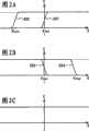
将参考附图2A至2C来说明用于本发明的MOS电容器元件。电容器元件由导电膜、绝缘膜和导电膜的堆叠层构成,并且具有两个端子(以下也称作不同于MOS电容器元件的普通电容器元件)。这种普通电容器元件不取决于电压并具有如图2C所示的恒定电容值。如在本发明中,在芯片中提供谐振电容器的情况下,优选地使用具有导电膜、绝缘膜和导电膜的堆叠结构的电容器元件,这是因为当将正信号或负信号输入到电容器元件的两端时其需要作为电容器元件来工作。A MOS capacitor element used in the present invention will be described with reference to FIGS. 2A to 2C. The capacitor element is composed of a stacked layer of a conductive film, an insulating film, and a conductive film, and has two terminals (hereinafter also referred to as a general capacitor element different from a MOS capacitor element). This general capacitor element is not dependent on voltage and has a constant capacitance value as shown in Fig. 2C. As in the present invention, in the case where a resonant capacitor is provided in a chip, it is preferable to use a capacitor element having a stacked structure of a conductive film, an insulating film, and a conductive film because when a positive signal or a negative signal is input to the capacitor element, At both ends it needs to work as a capacitor element.
同时,MOS电容器元件是由导电膜、绝缘膜和半导体区的堆叠层构成的电容器元件,并且具有在导电膜侧上的电极(电压:Vm)和在半导体区侧上的电极(电压:Vs)的两个端子。以下,通过与晶体管中名称的类推,可分别将导电膜侧上的电极和与导电膜侧上的电极重叠且在其间插入绝缘膜的半导体区称作栅电极和沟道形成区。Meanwhile, a MOS capacitor element is a capacitor element composed of a stacked layer of a conductive film, an insulating film, and a semiconductor region, and has an electrode (voltage: Vm ) on the conductive film side and an electrode (voltage: V m ) on the semiconductor region side.s ) of the two terminals. Hereinafter, by analogy with the names in transistors, the electrode on the conductive film side and the semiconductor region overlapping the electrode on the conductive film side with an insulating film interposed therebetween may be referred to as a gate electrode and a channel formation region, respectively.
N型MOS电容器元件具有阈值电压Vthn,其中,当满足Vm>Vs+Vthn时,在沟道形成区中形成N型反型层。所以,在Vm>Vs+Vthn时,沟道形成区具有导电性并用作普通电容器元件。P型MOS电容器元件具有阈值电压Vthp,其中,当满足Vm<Vs+Vthp时,在沟道形成区中形成P型反型层。所以,在Vm<Vs+Vthp时,沟道形成区具有导电性并用作普通电容器元件。在除以上情况外的条件下,电容值几乎为零。The N-type MOS capacitor element has a threshold voltage Vthn in which, when Vm >Vs +Vthn is satisfied, an N-type inversion layer is formed in the channel formation region. Therefore, when Vm > Vs + Vthn , the channel formation region has conductivity and functions as a general capacitor element. The P-type MOS capacitor element has a threshold voltage Vthp in which, when Vm < Vs +Vthp is satisfied, a P-type inversion layer is formed in the channel formation region. Therefore, when Vm < Vs + Vthp , the channel formation region has conductivity and functions as a general capacitor element. Under conditions other than the above, the capacitance value is almost zero.
图2A和2B中示出了这些行为特征。图2A示出了具有阈值电压Vthn1的N型MOS电容器元件的电容值C和电压V之间的关系201和具有阈值电压Vthn2的N型MOS电容器元件的电容值C和电压V之间的关系202。图2B示出了具有阈值电压Vthp1的P型MOS电容器元件的电容值C和电压V之间的关系203和具有阈值电压Vthp2的P型MOS电容器元件的电容值C和电压V之间的关系204。要注意,这些图示出了Vthn2<Vthn1和Vthp1<Vthp2的情况。These behavioral characteristics are shown in Figures 2A and 2B. 2A shows the
根据本发明的无线芯片的特征在于包括谐振电路,该谐振电路包括具有预定阈值电压的MOS电容器元件,如图2A或2B所示。A wireless chip according to the present invention is characterized by including a resonance circuit including a MOS capacitor element having a predetermined threshold voltage, as shown in FIG. 2A or 2B.
用于控制MOS电容器元件的阈值电压以具有预定值的方法包括一种通过离子掺杂或离子注入来控制在MOS电容器元件的沟道形成区中包括的杂质元素的浓度的方法。此外,通过适当地选择用于导电膜、绝缘膜和半导体区的材料能够将阈值电压控制到一定程度。The method for controlling the threshold voltage of the MOS capacitor element to have a predetermined value includes a method of controlling the concentration of an impurity element included in a channel formation region of the MOS capacitor element by ion doping or ion implantation. Furthermore, the threshold voltage can be controlled to a certain extent by appropriately selecting materials for the conductive film, the insulating film, and the semiconductor region.
要注意,根据本发明的包括在无线芯片中的谐振电路的特征是包括具有负阈值电压的N型MOS电容器元件或具有正阈值电压的P型MOS电容器元件。It is to be noted that the resonance circuit included in the wireless chip according to the present invention is characterized by including an N-type MOS capacitor element having a negative threshold voltage or a P-type MOS capacitor element having a positive threshold voltage.
在本发明中,在未产生高压的情况下,MOS电容器元件具有恒定的电容值。同时,为了具有恒定的电容值,N型MOS电容器元件具有负阈值电压(Vthn<0)而P型MOS电容器元件具有正阈值电压(Vthp>0)是必要的,这是因为交流电压被施加到用于本发明的MOS电容器元件上,并且正和负电压被施加在电容器元件的两个端子之间。In the present invention, the MOS capacitor element has a constant capacitance value without generating high voltage. Meanwhile, in order to have a constant capacitance value, it is necessary for the N-type MOS capacitor element to have a negative threshold voltage (Vthn <0) and the P-type MOS capacitor element to have a positive threshold voltage (Vthp >0) because the AC voltage is is applied to the MOS capacitor element used in the present invention, and positive and negative voltages are applied between the two terminals of the capacitor element.
本发明在功耗方面也具有优势。在使用限幅器电路和恒压产生电路的情况下,甚至在这些电路工作来防止产生过高电压时,所吸收的功率保持恒定。因为根据本发明的谐振电路通过移动谐振点来防止过高电压的产生,所以可以抑制自身的功率吸收。因此,可以减少功耗。The invention also has advantages in terms of power consumption. In the case of using a limiter circuit and a constant voltage generating circuit, even when these circuits operate to prevent generation of excessively high voltage, the absorbed power remains constant. Since the resonance circuit according to the present invention prevents the generation of excessive high voltage by moving the resonance point, it can suppress its own power absorption. Therefore, power consumption can be reduced.
这在读取多个芯片等的情况下尤其有效。当将多个芯片放在磁场中时,每个芯片的功率吸收影响磁场,从而导致芯片的谐振点偏移。所以,存在降低读取多个芯片的性能问题。本发明特别是在高功率吸收的情况下能抑制功率吸收,并且甚至在读取多个芯片的情况下,本发明也提供了极好的特性。This is especially effective in the case of reading multiple chips etc. When multiple chips are placed in a magnetic field, the power absorption of each chip affects the magnetic field, causing the resonance point of the chip to shift. Therefore, there is a problem of degrading the performance of reading multiple chips. The present invention suppresses power absorption particularly in the case of high power absorption, and provides excellent characteristics even in the case of reading a plurality of chips.
此外,在本发明中,因为未增加诸如限幅器电路或恒压产生电路的电路,所以能使电路面积较小。而且,与使用另外的绝缘膜的电容器元件的面积相比,当栅绝缘膜被用作MOS电容器元件的绝缘膜时,能使电容器元件的面积更小,这是因为栅绝缘膜较薄并且具有良好的膜品质。Furthermore, in the present invention, since circuits such as a limiter circuit or a constant voltage generating circuit are not added, the circuit area can be made smaller. Also, compared with the area of a capacitor element using another insulating film, when the gate insulating film is used as the insulating film of the MOS capacitor element, the area of the capacitor element can be made smaller because the gate insulating film is thinner and has Good film quality.
可将根据本发明的无线芯片形成在单晶硅衬底上,或者形成在玻璃衬底上,或者形成在诸如塑料基底的柔性基底上。The wireless chip according to the present invention may be formed on a single crystal silicon substrate, or on a glass substrate, or on a flexible substrate such as a plastic substrate.
特别地,根据无线芯片自身柔韧性的附加值,对于在诸如嵌入纸中和附接到曲面的各种应用中,在柔性衬底上形成芯片的方式是有益的。通常情况,在这些应用中读取多个芯片的能力是重要的,因此,本发明的观点是优选的。In particular, the way chips are formed on flexible substrates is beneficial for various applications such as embedding in paper and attaching to curved surfaces in terms of the added value of the flexibility of the wireless chip itself. Typically, the ability to read multiple chips is important in these applications, and therefore the aspects of the present invention are preferred.
特别地,与在单晶硅衬底上形成芯片的方式相比,在玻璃衬底上形成无线芯片的方式或将在玻璃衬底上形成的芯片转移到柔性基底的方式在成本上具有优势。这是因为玻璃衬底比单晶硅衬底大很多。另一方面,在玻璃衬底上形成芯片的方式存在大的芯片面积的问题。然而,可以说本发明方面是优选的,因为MOS电容器元件的面积较小且没有必要提供限幅器或恒压产生电路。In particular, the method of forming a wireless chip on a glass substrate or the method of transferring a chip formed on a glass substrate to a flexible substrate has an advantage in cost compared to a method of forming a chip on a single crystal silicon substrate. This is because glass substrates are much larger than monocrystalline silicon substrates. On the other hand, the method of forming a chip on a glass substrate has a problem of a large chip area. However, it can be said that the aspect of the invention is preferable because the area of the MOS capacitor element is small and it is not necessary to provide a limiter or a constant voltage generating circuit.
这里给出了本发明特定的多个方面。Certain aspects of the invention are presented herein.
根据本发明的半导体器件的一个方面具有包括具有负阈值电压的N型MOS电容器元件的谐振电路,其中通过天线无线发送和接收数据。An aspect of a semiconductor device according to the present invention has a resonance circuit including an N-type MOS capacitor element having a negative threshold voltage, in which data is wirelessly transmitted and received through an antenna.
特别地,N型MOS电容器元件的阈值电压在-0.1V至-24V的范围是优选的。In particular, it is preferable that the threshold voltage of the N-type MOS capacitor element is in the range of -0.1V to -24V.
此外,N型MOS电容器元件的阈值电压优选地具有作为最小工作电源电压的一半到最大工作电源电压的两倍的范围内的绝对值。Furthermore, the threshold voltage of the N-type MOS capacitor element preferably has an absolute value within a range of half the minimum operating power supply voltage to twice the maximum operating power supply voltage.
此外,N型MOS电容器元件的半导体区域优选地包括浓度为1×10¹⁷原子/立方厘米至1×1020原子/立方厘米的N型杂质元素。Furthermore, the semiconductor region of the N-type MOS capacitor element preferably includes an N-type impurity element at a concentration of 1×10¹⁷ atoms/cm 3 to 1×10²⁰ atoms/cm 3 .
根据本发明的半导体器件的另一方面是具有包括具有正阈值电压的P型MOS电容器元件的谐振电路,其中通过天线无线发送和接收数据。Another aspect of the semiconductor device according to the present invention is to have a resonance circuit including a P-type MOS capacitor element having a positive threshold voltage, in which data is wirelessly transmitted and received through an antenna.
特别地,P型MOS电容器元件的阈值电压优选地在0.1V至24V的范围内。In particular, the threshold voltage of the P-type MOS capacitor element is preferably in the range of 0.1V to 24V.
此外,P型MOS电容器元件的阈值电压优选地具有作为最小工作电源电压的一半到最大工作电源电压的两倍的范围内的绝对值。Furthermore, the threshold voltage of the P-type MOS capacitor element preferably has an absolute value within a range of half the minimum operating power supply voltage to twice the maximum operating power supply voltage.
此外,P型MOS电容器元件的半导体区域优选地包括浓度为1×10¹⁷原子/立方厘米至1×1020原子/立方厘米的P型杂质元素。Furthermore, the semiconductor region of the P-type MOS capacitor element preferably includes a P-type impurity element at a concentration of 1×10¹⁷ atoms/cm 3 to 1×10²⁰ atoms/cm 3 .
根据本发明的半导体器件可具有设置在玻璃衬底或柔性衬底上的集成电路。A semiconductor device according to the present invention may have an integrated circuit provided on a glass substrate or a flexible substrate.
根据本发明的半导体器件可具有包括薄膜晶体管的集成电路。A semiconductor device according to the present invention may have an integrated circuit including thin film transistors.
本发明的另一方面是配备有上述半导体器件的票据、硬币、证券、证书、不记名债券、用于包装的容器、书本、存储介质、车辆、食品、服装、保健品、日用品、药品或者电子设备等。Another aspect of the present invention is bills, coins, securities, certificates, bearer bonds, containers for packaging, books, storage media, vehicles, food, clothing, health products, daily necessities, medicines, or electronic devices equipped with the above-mentioned semiconductor devices. equipment etc.
本发明能够实现一种具有高可靠性的无线芯片,其防止在诸如接近天线的情况下的强磁场中内部产生的电压极大增加。The present invention can realize a wireless chip with high reliability that prevents an internally generated voltage from greatly increasing in a strong magnetic field such as in the case of proximity to an antenna.
此外,能够实现一种具有小的芯片面积的无线芯片,这是因为未增加诸如限幅器电路和恒压产生电路的额外电路。Furthermore, it is possible to realize a wireless chip with a small chip area because additional circuits such as a limiter circuit and a constant voltage generation circuit are not added.
此外,由于根据本发明的谐振电路通过移动谐振点来防止过大电压的产生,所以,与使用限幅器电路和恒压产生电路的情况不一样,其可以抑制自身的功率吸收。所以,可以降低功耗。本发明尤其在多个芯片需要被读取的应用中具有良好的效果。Furthermore, since the resonance circuit according to the present invention prevents the generation of excessive voltage by moving the resonance point, it can suppress its own power absorption unlike the case of using a limiter circuit and a constant voltage generating circuit. Therefore, power consumption can be reduced. The invention works especially well in applications where multiple chips need to be read.
此外,可认为在柔性基底上形成无线芯片的方式可用于各种应用,并且本发明用于抑制功率吸收的方面在读取多个芯片的情况下是有效的。所以,可以在各种应用中获得一致的效果。In addition, it is considered that the manner of forming a wireless chip on a flexible substrate can be used for various applications, and the aspect of the present invention for suppressing power absorption is effective in the case of reading a plurality of chips. Therefore, consistent effects can be obtained in various applications.
附图说明Description of drawings
图1A至1D是根据本发明的半导体器件的简图和用于解释其工作的曲线图。1A to 1D are schematic diagrams of a semiconductor device according to the present invention and graphs for explaining its operation.
图2A至2C是包括在根据本发明的半导体器件中的MOS电容器元件的特征曲线。2A to 2C are characteristic curves of a MOS capacitor element included in a semiconductor device according to the present invention.
图3A至3C是传统的半导体器件的简图和用于解释其工作的曲线图。3A to 3C are schematic diagrams of a conventional semiconductor device and graphs for explaining its operation.
图4A至4D是根据本发明的半导体器件的简图和用于解释其工作的曲线图。4A to 4D are schematic diagrams of a semiconductor device according to the present invention and graphs for explaining its operation.
图5是根据本发明的半导体器件的框图。FIG. 5 is a block diagram of a semiconductor device according to the present invention.
图6A至6C是根据本发明的半导体器件的电源电路。6A to 6C are power supply circuits of the semiconductor device according to the present invention.
图7A至7C是根据本发明的半导体器件的电源电路。7A to 7C are power supply circuits of the semiconductor device according to the present invention.
图8是根据本发明的半导体器件的简图。Fig. 8 is a schematic diagram of a semiconductor device according to the present invention.
图9是根据本发明的半导体器件的简图。Fig. 9 is a schematic diagram of a semiconductor device according to the present invention.
图10A和10B是根据本发明的半导体器件的简图和用于解释其工作的曲线图。10A and 10B are schematic diagrams of a semiconductor device according to the present invention and graphs for explaining its operation.
图11A和11B是根据本发明的半导体器件的简图和用于解释其工作的曲线图。11A and 11B are schematic diagrams of a semiconductor device according to the present invention and graphs for explaining its operation.
图12是包括在根据本发明的半导体器件中的MOS电容器元件的布局图。FIG. 12 is a layout view of a MOS capacitor element included in a semiconductor device according to the present invention.
图13A至13C是图解说明用于制造根据本发明的半导体器件的方法的图。13A to 13C are diagrams illustrating a method for manufacturing a semiconductor device according to the present invention.
图14A和14B是图解说明用于制造根据本发明的半导体器件的方法的图。14A and 14B are diagrams illustrating a method for manufacturing a semiconductor device according to the present invention.
图15A和15B是图解说明用于制造根据本发明的半导体器件的方法的图。15A and 15B are diagrams illustrating a method for manufacturing a semiconductor device according to the present invention.
图16A和16B是图解说明用于制造根据本发明的半导体器件的方法的图。16A and 16B are diagrams illustrating a method for manufacturing a semiconductor device according to the present invention.
图17是图解说明用于制造根据本发明的半导体器件的方法的图。FIG. 17 is a diagram illustrating a method for manufacturing a semiconductor device according to the present invention.
图18是图解说明用于制造根据本发明的半导体器件的方法的图。FIG. 18 is a diagram illustrating a method for manufacturing a semiconductor device according to the present invention.
图19是包括在根据本发明的半导体器件中的电路的布局图。FIG. 19 is a layout diagram of a circuit included in a semiconductor device according to the present invention.
图20是包括在根据本发明的半导体器件中的电路的布局图。FIG. 20 is a layout diagram of a circuit included in a semiconductor device according to the present invention.
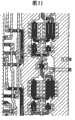
图21是根据本发明的半导体器件的电路的布局图。FIG. 21 is a layout diagram of a circuit of a semiconductor device according to the present invention.
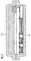
图22是包括在根据本发明的半导体器件中的半导体器件的截面图。22 is a cross-sectional view of a semiconductor device included in the semiconductor device according to the present invention.
图23A至23E是包括在根据本发明的半导体器件中的半导体元件的布局图。23A to 23E are layout views of semiconductor elements included in the semiconductor device according to the present invention.
图24A至24G是示出配备有根据本发明的半导体器件的半导体器件的图。24A to 24G are diagrams showing a semiconductor device equipped with a semiconductor device according to the present invention.
图25A和25B是包括在根据本发明的半导体器件中的电路的布局图。25A and 25B are layout views of circuits included in the semiconductor device according to the present invention.
图26A和26B是包括在根据本发明的半导体器件中的电路的布局图。26A and 26B are layout views of circuits included in the semiconductor device according to the present invention.
图27A和27B是包括在根据本发明的半导体器件中的电路的布局图。27A and 27B are layout views of circuits included in the semiconductor device according to the present invention.
图28A和28B是应用根据本发明的半导体器件的示例的流程图。28A and 28B are flowcharts of examples of applying the semiconductor device according to the present invention.
图29是应用根据本发明的半导体器件的系统配置示例。FIG. 29 is an example of a system configuration to which a semiconductor device according to the present invention is applied.
图30A和30B是应用根据本发明的半导体器件的示例。30A and 30B are examples of applying the semiconductor device according to the present invention.
具体实施方式Detailed ways
将参考附图来详细描述本发明的实施方式和实施例。然而,本发明可以以各种不同的方式来实现,并且本领域的技术人员将容易理解在不偏离本发明的精神和范围内的情况下可以做出形式上和细节上的各种改变。所以不认为将本发明解释为受实施方式和实施例描述的限制。应该注意到在描述实施方式和实施例的所有附图中,相同的附图标记用于相同的部分或具有相同功能的部分,并且将省略对其重复描述。Embodiment modes and examples of the present invention will be described in detail with reference to the drawings. However, the present invention can be carried out in various ways, and those skilled in the art will readily understand that various changes in form and details can be made without departing from the spirit and scope of the present invention. Therefore, it is not considered that the present invention is construed as being limited by the description of the embodiments and examples. It should be noted that in all the drawings describing the embodiments and examples, the same reference numerals are used for the same parts or parts having the same functions, and repeated descriptions thereof will be omitted.
(实施方式1)(Embodiment 1)
在本发明的实施方式中,将描述用于本发明的谐振电路。可以认为这是根据本发明的无线芯片的最简单方式。In the embodiments of the present invention, a resonance circuit used in the present invention will be described. This can be considered the simplest way of the wireless chip according to the invention.
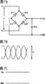
首先,将参考附图3A至3C来描述传统的谐振电路。图3A示出了包括串联连接的具有电感L的环形天线、阻值为R的电阻元件和电容值为C的电容器元件的谐振电路,并且示出了向谐振电路提供功率的天线(电感:LR;电流:iR)。可以认为这是表示传统的无线芯片和利用该无线芯片发送和接收数据的器件(以下称作读取器)的简化模型。当假设M和ω分别表示图3A中两个天线之间的互感和角频率时,公式1给出了在电容器元件的相对端之间感生的交流电压的振幅V。特别地,将满足ω2LC=1的情况称为谐振条件,其中,电压振幅V最大。First, a conventional resonance circuit will be described with reference to FIGS. 3A to 3C. 3A shows a resonance circuit including a loop antenna having an inductance L, a resistance element having a resistance value R, and a capacitor element having a capacitance value C connected in series, and shows the antenna (inductance: L) that supplies power to the resonance circuit.R ; current: iR ). This can be considered as a simplified model representing a conventional wireless chip and a device (hereinafter referred to as a reader) that transmits and receives data using the wireless chip.
[公式1][Formula 1]
图3B示出了电容值C和电压振幅V之间的关系。曲线(1)和曲线(2)的互感值不同,并且曲线(2)具有更大的互感。当无线芯片和读取器之间的距离或者无线芯片和读取器的布置变化时,互感改变,并且例如,无线芯片和读取器之间的距离减少越多,互感就越大。图3C示出了互感M和电压振幅V之间的关系。电压振幅V与互感M成比例,如图3C所示。FIG. 3B shows the relationship between the capacitance value C and the voltage amplitude V. As shown in FIG. Curve (1) and curve (2) have different mutual inductance values, and curve (2) has a greater mutual inductance. When the distance between the wireless chip and the reader or the arrangement of the wireless chip and the reader is changed, the mutual inductance changes, and for example, the more the distance between the wireless chip and the reader is reduced, the greater the mutual inductance. Fig. 3C shows the relationship between the mutual inductance M and the voltage amplitude V. The voltage amplitude V is proportional to the mutual inductance M, as shown in Figure 3C.
接着,将参考附图4A至4D来描述用于本发明的谐振电路。图4A示出了包括串联连接的具有电感L的环形天线、阻值为R的电阻元件和N型MOS电容器元件401的谐振电路,并且示出了向该谐振电路提供功率的天线(电感:LR;电流:iR)。可以认为这是表示根据本发明的无线芯片和读取器的简化模型。Next, a resonant circuit used in the present invention will be described with reference to FIGS. 4A to 4D. 4A shows a resonance circuit including a loop antenna having an inductance L, a resistance element having a resistance value R, and an N-type
当假设M、ω和CMOS分别表示图4A中两个天线之间的互感、角频率和N型MOS电容器元件401的电容值时,如图3A中一样由公式1给出在电容器元件的相对端之间感生的交流电压的振幅V。When it is assumed that M, ω, and CMOS represent the mutual inductance between the two antennas in FIG. 4A, the angular frequency, and the capacitance value of the N-type
同时,当为图4A所示的半导体器件感生交流电压时,相对于电压振幅V的电容值CMOS的行为特征如图4B所示。N型MOS电容器元件401的电容值CMOS根据电压振幅V是否大于阈值电压的绝对值(-Vthn)而改变。当电压振幅V没有超过阈值电压的绝对值(V<-Vthn)时,N型MOS电容器元件401的行为特征如同普通电容器元件(电容值C1)。当电压振幅V超过阈值电压的绝对值(V>-Vthn)时,N型MOS电容器元件401的电容值是在C1和0之间的值。然后,电压振幅增加越大,那么形成反型层的时间段越短,并且电容值变得接近0。Meanwhile, when an AC voltage is induced for the semiconductor device shown in FIG. 4A, the behavior characteristics of the capacitance value CMOS with respect to the voltage amplitude V are as shown in FIG. 4B. The capacitance valueCMOS of the N-type
因此,在电容值C1满足谐振条件(ω2LC=1)时感生的交流电压振幅V如图4C所表示。在图4C中,实线示出了交流电压振幅V和电容值CMOS之间的关系。虚线示出了在改变电容值的情况下交流电压振幅V和电容值之间的关系。Therefore, when the capacitance C1 satisfies the resonance condition (ω2 LC=1), the induced AC voltage amplitude V is shown in FIG. 4C . In FIG. 4C, the solid line shows the relationship between the AC voltage amplitude V and the capacitance value CMOS . The dotted line shows the relationship between the AC voltage amplitude V and the capacitance value in the case of changing the capacitance value.
图4C中的实线对应于当互感变化时电压振幅的轨迹。当互感较小时(虚线(1)),电压振幅V比N型MOS电容器元件401的阈值电压的绝对值小,并且电容值CMOS与电容值C1(点A)一致。同时,当例如通过使无线芯片靠近读取器而使互感增加时(虚线(2)),在普通电容器元件的情况下产生虚线(2)的峰值(点C)电压。然而,因为点C的电压振幅V大于N型MOS电容器元件401的阈值电压的绝对值,所以使电容值CMOS减小,由此而偏离谐振条件,并且感生电压因此得到了控制(点B)。The solid line in Figure 4C corresponds to the locus of the voltage amplitude as the mutual inductance varies. When the mutual inductance is small (dotted line (1)), the voltage amplitude V is smaller than the absolute value of the threshold voltage of the N-type
图4D示出了互感M和电压振幅V之间的关系。当电压振幅V超过N型MOS电容器元件401的阈值电压的绝对值时,将电容值CMOS变成偏离谐振条件,并且感生电压因此得到了控制。所以,电压振幅V和互感M不再具有比例关系。Figure 4D shows the relationship between mutual inductance M and voltage amplitude V. When the voltage amplitude V exceeds the absolute value of the threshold voltage of the N-type
要注意,N型MOS电容器元件的阈值电压需要为负(Vth<0),这是因为当将小振幅的交流电压施加到MOS电容器元件时必须作为普通电容器元件工作。It is to be noted that the threshold voltage of the N-type MOS capacitor element needs to be negative (Vth <0), because the MOS capacitor element must work as a normal capacitor element when a small-amplitude AC voltage is applied to the MOS capacitor element.
响应于上述图4C和4D的行为特征,本发明实现了能够防止在芯片中产生过高电压的无线芯片,即,其具有限幅器功能。此外,基于为电容器元件产生的交流电压而产生提供给无线芯片中的逻辑电路的电源电压。所以,用于MOS电容器元件的阈值电压的适当值使得提供给内部逻辑电路的电源电压的过大增加得到了防止。In response to the behavior characteristics of FIGS. 4C and 4D described above, the present invention realizes a wireless chip capable of preventing excessive voltage from being generated in the chip, that is, it has a limiter function. Furthermore, the power supply voltage supplied to the logic circuit in the wireless chip is generated based on the AC voltage generated for the capacitor element. Therefore, an appropriate value for the threshold voltage of the MOS capacitor element enables an excessive increase in the power supply voltage supplied to the internal logic circuit to be prevented.
如上所述,本发明实现了具有高可靠性的无线芯片,其通过使用具有受控的阈值电压的MOS电容器元件,即使在靠近天线的情况下也防止提供给内部逻辑电路的电源电压过大增加。此外,可以实现具有小芯片面积的无线芯片,这是因为没有增加诸如限幅器电路和恒压产生电路的额外电路。As described above, the present invention realizes a wireless chip with high reliability that prevents an excessive increase in power supply voltage supplied to an internal logic circuit even in the case of proximity to an antenna by using a MOS capacitor element having a controlled threshold voltage . Furthermore, a wireless chip with a small chip area can be realized because additional circuits such as a limiter circuit and a constant voltage generation circuit are not added.
此外,由于根据本发明的谐振电路通过偏离谐振点来防止过高电压的产生,所以与使用限幅器电路或恒压产生电路的情况不同,其可以防止自身的功率吸收。所以,可以降低功耗。Furthermore, since the resonance circuit according to the present invention prevents generation of excessively high voltage by shifting the resonance point, it can prevent its own power absorption unlike the case of using a limiter circuit or a constant voltage generating circuit. Therefore, power consumption can be reduced.
要注意,尽管用N型MOS电容器元件作为图4A至4D中所示方式中的MOS电容器元件,但在本发明中也可能使用P型MOS电容器元件。在这种情况下,通过包括P型MOS电容器元件801的电路图来表示一种方式,如图8所示。此外,当将N型MOS电容器元件的阈值电压的绝对值(-Vthn)改变为被认为是P型MOS电容器元件的阈值电压的绝对值(Vthp)时,不作改变地适用图4B至4D以及本实施方式的描述。特别地,本发明在使用P型MOS电容器元件的情况下具有阈值电压为正(Vtbp>0)的特征。It is to be noted that although an N-type MOS capacitor element is used as the MOS capacitor element in the manner shown in FIGS. 4A to 4D, it is also possible to use a P-type MOS capacitor element in the present invention. In this case, one mode is represented by a circuit diagram including a P-type
(实施方式2)(Embodiment 2)
在本实施方式中,将参考附图1A至1D来描述根据本发明的无线芯片。图1A示出的电路包括:具有电感L、寄生电阻ra和寄生电容Ca的天线102;包括N型MOS电容器元件105的谐振电容103;具有电阻值RL的电阻元件;以及具有电容值CL的电容器元件,它们被并联连接在一起,并且图1A示出了向该电路提供功率的天线(电感:LR;电流:iR)。具有电阻值RL的电阻元件和具有电容值CL的电容器元件表示无线芯片的电路部分104,并且可以认为图1A是表示根据本发明的半导体器件100和读取器101的简化模型。In this embodiment mode, a wireless chip according to the present invention will be described with reference to FIGS. 1A to 1D. The circuit shown in Fig. 1A includes: an antenna 102 with an inductance L, a parasitic resistance ra and a parasitic capacitance Ca ; a resonant capacitor 103 comprising an N-type MOS capacitor element 105; a resistive element with a resistance valueRL ; The capacitor elements ofCL , which are connected together in parallel, and Fig. 1A shows the antenna (inductance:LR ; current:iR ) that supplies power to this circuit. A resistive element having a resistance value RL and a capacitor element having a capacitance valueCL represent the circuit portion 104 of the wireless chip, and FIG. 1A can be considered to represent a simplified model of the semiconductor device 100 and the reader 101 according to the present invention.
当假设M、ω和Ctot分别表示图1A中两个天线之间的互感;角频率以及天线的寄生电容值Ca、N型MOS电容器元件105的电容值和电路部分的电容值CL的总和时,在电容器元件相对端之间感生的交流电压的振幅V由公式2给出。When it is assumed that M, ω and Ctot respectively represent the mutual inductance between the two antennas in Fig. 1A; the sum of the angular frequency and the parasitic capacitance value Ca of the antenna, the capacitance value of the N-type MOS capacitor element 105 and the capacitance valueCL of the circuit part , the amplitude V of the AC voltage induced between the opposite ends of the capacitor element is given by
[公式2][Formula 2]
同时,当为图1A中所示的半导体器件100感生交流电压时,电容值Ctot相对于电压振幅V的行为特征如图1B中所示来表示。N型MOS电容器元件105的电容值取决于电压振幅V是否大于阈值电压的绝对值(-Vthn)而改变。当电压振幅V没有超过阈值电压的绝对值(V<-Vthn)时,N型MOS电容器元件105的行为特征如普通电容器元件(在当V<-Vthn得到满足时Ctot是C1的情况下,电容值是C1-Ca-CL)。当电压振幅V超过阈值电压的量值(V>-Vthn)时,N型MOS电容器元件105的电容值是C1-Ca-CL和0之间的值。然后,使电压振幅增加越大,形成反型层的时间段越短,并且电容值变得接近0。所以,Ctot的电容值变得接近Ca+CL。Meanwhile, when an AC voltage is induced for the semiconductor device 100 shown in FIG. 1A , the behavior characteristic of the capacitance value Ctot with respect to the voltage amplitude V is expressed as shown in FIG. 1B . The capacitance value of the N-type MOS capacitor element 105 changes depending on whether the voltage amplitude V is larger than the absolute value of the threshold voltage (-Vthn ). When the voltage amplitude V does not exceed the absolute value of the threshold voltage (V<-Vthn ), the N-type MOS capacitor element 105 behaves like an ordinary capacitor element (Ctot is C1 when V<-Vthn is satisfied Below, the capacitance value is C1 -Ca-CL ). When the voltage amplitude V exceeds the magnitude of the threshold voltage (V>-Vthn ), the capacitance value of the N-type MOS capacitor element 105 is a value between C1 -Ca-CL and zero. Then, the more the voltage amplitude is increased, the shorter the time period for forming the inversion layer, and the capacitance value becomes closer to 0. Therefore, the capacitance value of Ctot becomes close to Ca +CL .
因此,当电容值C1满足谐振条件时所感生的交流电压振幅V如图1C所表示。在图1C中,实线示出了交流电压振幅V和电容值Ctot之间的关系。虚线示出了在改变电容值的情况下交流电压振幅V和的电容值之间的关系。Therefore, when the capacitance C1 satisfies the resonance condition, the induced AC voltage amplitude V is shown in FIG. 1C . In FIG. 1C, the solid line shows the relationship between the AC voltage amplitude V and the capacitance value Ctot . The dotted line shows the relationship between the AC voltage amplitude V and the capacitance value in the case of changing the capacitance value.
图1C中的实线对应于当改变互感时的电压振幅的轨迹。当互感较小(虚线(1))时,电压振幅V小于N型MOS电容器元件105的阈值电压的绝对值,而电容值CZtot与电容值C1(点A)一致。同时,当例如通过使无线芯片靠近读取器而增加互感时(虚线(2)),在普通电容器元件的情况下产生虚线(2)的峰值(点C)电压。然而,因为点C的电压振幅V大于N型MOS电容器元件105的阈值电压的绝对值,所以电容值Ctot被减少以至于偏离谐振条件,并且感生电压因此得到了控制(点B)。The solid line in Fig. 1C corresponds to the locus of the voltage amplitude when changing the mutual inductance. When the mutual inductance is small (dotted line (1)), the voltage amplitude V is smaller than the absolute value of the threshold voltage of the N-type MOS capacitor element 105, and the capacitance CZtot coincides with the capacitance C1 (point A). Meanwhile, when the mutual inductance is increased (dashed line (2)), for example by bringing the wireless chip close to the reader, the peak (point C) voltage of the dashed line (2) is generated in the case of a normal capacitor element. However, since the voltage amplitude V at point C is larger than the absolute value of the threshold voltage of the N-type MOS capacitor element 105, the capacitance value Ctot is reduced so as to deviate from the resonance condition, and the induced voltage is thus controlled (point B).
图1D示出了互感M和电压振幅V之间的关系。当电压振幅V超过N型MOS电容器元件105的阈值电压时,电容值Ctot被改变而偏离谐振条件,并且感生电压因此得到了控制。所以,电压振幅V和互感M不再具有比例关系。Figure 1D shows the relationship between mutual inductance M and voltage amplitude V. When the voltage amplitude V exceeds the threshold voltage of the N-type MOS capacitor element 105, the capacitance value Ctot is changed to deviate from the resonance condition, and the induced voltage is thus controlled. Therefore, the voltage amplitude V and the mutual inductance M no longer have a proportional relationship.
响应于上述图1C和1D的行为特征,本发明实现了能防止在芯片中产生过大电压的无线芯片,即,具有限幅器功能的无线芯片。此外,提供给无线芯片中逻辑电路的电源电压基于为电容器元件产生的交流电压而产生。所以,用于MOS电容器元件的阈值电压的适当值使得提供给内部逻辑电路的电源电压的过大增加得到了防止。In response to the behavior characteristics of FIGS. 1C and 1D described above, the present invention realizes a wireless chip capable of preventing excessive voltage from being generated in the chip, that is, a wireless chip having a limiter function. In addition, the power supply voltage supplied to the logic circuit in the wireless chip is generated based on the AC voltage generated for the capacitor element. Therefore, an appropriate value for the threshold voltage of the MOS capacitor element enables an excessive increase in the power supply voltage supplied to the internal logic circuit to be prevented.
如上所述,本发明实现了具有高可靠性的无线芯片,其通过使用具有受控阈值电压的MOS电容器元件,甚至在靠近天线的情况下,也防止提供给内部逻辑电路的电源电压的过大增加。此外,可以实现具有小的芯片面积的无线芯片,这是因为没有增加诸如限幅器电路和恒压产生电路的额外电路。As described above, the present invention realizes a wireless chip with high reliability that prevents excessive power supply voltage supplied to an internal logic circuit by using a MOS capacitor element with a controlled threshold voltage even in the case of being close to an antenna Increase. Furthermore, a wireless chip with a small chip area can be realized because additional circuits such as a limiter circuit and a constant voltage generation circuit are not added.
此外,由于根据本发明的谐振电路通过偏离谐振点来防止过大电压的产生,所以,与使用限幅器电路和恒压产生电路的情况不同,其可以防止自身的功率吸收。所以,可以降低功耗。Furthermore, since the resonance circuit according to the present invention prevents the generation of excessive voltage by shifting the resonance point, it can prevent its own power absorption unlike the case of using a limiter circuit and a constant voltage generating circuit. Therefore, power consumption can be reduced.
要注意,尽管在图1A至1D示出的方式中用N型MOS电容器元件作MOS电容器元件,在本发明中也可能使用P型MOS电容器元件。在那种情况下,通过如图9所示的包括半导体器件900和读取器901的电路图来表示一种方式,该半导体器件900具有天线902、谐振电路903和电路部分904。谐振电路903具有P型MOS电容器元件905。此外,当将N型MOS电容器元件的阈值电压的绝对值(-Vthn)改变为被认为是P型MOS电容器元件的阈值电压的绝对值(Vthp)时,不作改变地适用图1B至1D以及本实施方式的描述。It is to be noted that although an N-type MOS capacitor element is used as the MOS capacitor element in the manner shown in FIGS. 1A to 1D, it is also possible to use a P-type MOS capacitor element in the present invention. In that case, one mode is represented by a circuit diagram including a
(实施方式3)(Embodiment 3)
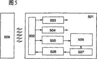
图5示出了根据本发明的半导体器件的配置。根据本发明的半导体器件501通过从读取器509发射的电磁波而被提供功率,并且利用该读取器来无线发送和接收数据。此外,通过通信线路可将读取器连接到计算机,以便在计算机的控制下相对于半导体器件发送和接收数据。FIG. 5 shows the configuration of a semiconductor device according to the present invention. The
半导体器件501具有包括MOS电容器元件的谐振电路502、电源电路503、时钟发生电路504、解调电路505、控制电路506、存储器部分507以及编码和调制电路508。将天线电连接到谐振电路中的MOS电容器元件。关于天线,利用包括在半导体器件501中的天线或者通过连接端子电连接到MOS电容器元件的外部天线。The
在谐振电路502中,当接收从读取器509发射的电磁波时,感生交流电压。该交流电压包括从读取器发送的数据,并且也是用于半导体器件501的电源和时钟信号的基础。In the
电源电路503利用整流元件对谐振电路502中产生的交流电压进行整流,并向每个电路提供通过使用电容器元件而被稳定的电源。基于谐振电路502产生的交流电压,时钟发生电路504产生具有预定频率的时钟信号。解调电路505响应谐振电路502中产生的交流电压对数据进行解调。控制电路506对存储器部分507进行控制以根据解调的数据从存储器中进行读取以及向存储器进行写入等。存储器部分507由非易失性EEPROM和FeRAM以及易失性SRAM等构成,并且存储器部分507至少优选地具有非易失性存储器。将特定于半导体器件501等的数据保存在非易失性存储器中。编码和调制电路508将要发送的数据转换成编码信号并调制载波。The
要注意,半导体器件501可包括天线或者可具有连接天线的端子。此外,半导体器件501不限于上述配置,而可以具有信息判断电路、中央处理单元(CPU)和拥塞控制电路等等。尽管描述了没有电池的无源配置,但是可以使用具有电池的有源配置。It is to be noted that the
电源电路503产生电源电压VDD并将电源提供给每个电路。为了确保可靠的工作,无线芯片具有电源电压VDD的Vmin至Vmax的范围。这些最小工作电源电压Vmin和最大工作电源电压Vmax的值取决于集成电路技术,并且在集成电路形成于单晶硅的情况下,Vmin和Vmax分别是大约0.2至1V和大约1至5V。此外,在集成电路形成于玻璃衬底或柔性衬底的情况下,Vmin和Vmax分别是大约1至4V和大约3至12V。The
根据这些电源电压的范围,本发明实现了一种无线芯片,其能通过使用具有预定阈值电压的MOS电容器元件且在未提供限幅器电路或恒压产生电路的情况下来防止内部电压极大增加。当在N型MOS电容器元件的情况下预定阈值电压是在-0.1V至-24V的范围内,而在P型MOS电容器元件的情况下预定阈值电压是在0.1V至24V的范围内时,本发明是有效的。特别地,在将MOS电容器元件形成于包括具有2μm或更短栅长的集成电路的柔性衬底或玻璃衬底之上的情况下,预定阈值电压优选地是-2V至-15V(N型MOS电容器元件)和2V至15V(P型MOS电容器元件)。According to the range of these power supply voltages, the present invention realizes a wireless chip capable of preventing the internal voltage from greatly increasing by using a MOS capacitor element having a predetermined threshold voltage without providing a limiter circuit or a constant voltage generating circuit . When the predetermined threshold voltage is in the range of -0.1V to -24V in the case of the N-type MOS capacitor element and in the range of 0.1V to 24V in the case of the P-type MOS capacitor element, the present Invention works. In particular, in the case of forming a MOS capacitor element over a flexible substrate or a glass substrate including an integrated circuit having a gate length of 2 μm or less, the predetermined threshold voltage is preferably -2 V to -15 V (N-type MOS capacitor element) and 2V to 15V (P-type MOS capacitor element).
[实施例1][Example 1]
将参考附图6A至6C和附图7A至7C来描述包括在根据本发明的无线芯片中的电源电路的示例。An example of a power supply circuit included in a wireless chip according to the present invention will be described with reference to FIGS. 6A to 6C and FIGS. 7A to 7C.
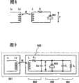
图6A示出了半波整流电源电路的配置示例。该电源电路具有:两个输入端子,该两个输入端子被连接到天线的相对端或者通过电容器元件等与其相连;两个输出端子,其输出GND和VDD;两个二极管601和602以及电容器元件603。将两个输入端子之一和两个输出端子之一直接连接以具有地电压GND。在具有该配置的电源电路中,当要被输入的交流信号如图6B中所示时,输出如图6C所示并且电源电压VDD是(2×V-2×Vthd)或更小。要注意,Vthd表示二极管的阈值电压。FIG. 6A shows a configuration example of a half-wave rectification power supply circuit. This power supply circuit has: two input terminals connected to opposite ends of the antenna or connected thereto through a capacitor element or the like; two output terminals which output GND and VDD; two
图7A示出了全波整流电源电路的配置示例。该电源电路具有:两个输入端子,该两个输入端子被连接到天线的相对端或者通过电容器元件等与其相连;两个输出端子,其输出GND和VDD;四个二极管611、612、613和614以及电容器元件615。在具有该配置的电源电路中,当要被输入的交流信号如图7B所示时,输出如图7C所示,并且电源电压VDD是大约V-2×Vthd。要注意,Vthd表示二极管的阈值电压。FIG. 7A shows a configuration example of a full-wave rectification power supply circuit. This power supply circuit has: two input terminals which are connected to the opposite ends of the antenna or connected thereto through a capacitor element or the like; two output terminals which output GND and VDD; four
为了确保可靠的工作,无线芯片的电源电压VDD具有Vmin至Vmax的范围。在使用根据本发明的谐振电路的情况下,当交流电压振幅V等于或大于MOS电容器元件的阈值电压的绝对值Vth时,施加抑制动作。所以,电压Vmin至Vmax和阈值电压的绝对值Vtb优选地具有下列关系。In order to ensure reliable operation, the power supply voltage VDD of the wireless chip has a range of Vmin to Vmax . In the case of using the resonant circuit according to the present invention, when the AC voltage amplitude V is equal to or greater than the absolute valueVth of the threshold voltage of the MOS capacitor element, the suppression action is applied. Therefore, the voltages Vmin to Vmax and the absolute value Vtb of the threshold voltage preferably have the following relationship.
首先,为了在不损坏电路部分的情况下执行具有高可靠性的工作,有必要抑制要产生的电源电压到Vmax或更小。所以,在图6A所示的电源电路中,电源电压优选地是2×Vth-2×Vthd<Vmax,而在图7A所示的电源电路中,电源电压是Vth-2×Vthd<Vmax.First, in order to perform work with high reliability without damaging circuit parts, it is necessary to suppress the power supply voltage to be generated to Vmax or less. Therefore, in the power supply circuit shown in FIG. 6A, the power supply voltage is preferably 2×Vth −2×Vthd <Vmax , while in the power supply circuit shown in FIG. 7A, the power supply voltage is Vth −2×Vthd < Vmax .
此外,当所产生的电压由MOS电容控制且等于或小于工作保证电压时,导致甚至在使无线芯片靠近读取器时无线芯片不进行工作的状态。为了避免这种状态,在图6A所示的电源电路中,电源电压优选地是Vmin<2×Vth-2×Vthd,而在图7A所示的电源电路中,电源电压是Vmin<Vth-2×Vthd。Furthermore, when the generated voltage is controlled by the MOS capacitance and is equal to or less than the operation guaranteed voltage, it results in a state where the wireless chip does not operate even when the wireless chip is brought close to the reader. In order to avoid this state, in the power supply circuit shown in FIG. 6A, the power supply voltage is preferably Vmin < 2×Vth −2×Vthd , while in the power supply circuit shown in FIG. 7A, the power supply voltage is Vmin < Vth −2×Vthd .
此外,用另一方式表达,可以说,分别地,对于具有半波整流电源电路的无线芯片,优选地使用具有满足公式3的Vth的MOS电容器元件,而对于具有全波整流电源电路的无线芯片,优选地使用具有满足公式4的Vth的MOS电容器元件。要注意,Vth表示MOS电容器元件的阈值电压的绝对值。Furthermore, expressed in another way, it can be said that, respectively, for a wireless chip with a half-wave rectification power supply circuit, it is preferable to use a MOS capacitor element with a Vth satisfying formula 3, while for a wireless chip with a full-wave rectification power supply circuit chip, preferably using a MOS capacitor element with a Vth satisfying Equation 4. It is to be noted that Vth represents the absolute value of the threshold voltage of the MOS capacitor element.
[公式3][Formula 3]
[公式4][Formula 4]
Vmin+2Vthd<Vth<Vmax+2VthdVmin +2Vthd <Vth <Vmax +2Vthd
还可用另一种方式来表达,可以说,当在交流电压振幅V和电源电压VDD之间满足关系VDD=c×V时,优选地使用具有满足公式5的Vth的MOS电容器元件。因为系数c通常是在1/4至1的范围,所以MOS电容器元件优选地具有满足公式6的Vth。Expressed in another way, it can be said that when the relationship VDD=c×V is satisfied between the AC voltage amplitude V and the power supply voltage VDD, it is preferable to use a MOS capacitor element having aVth
[公式5][Formula 5]
[公式6][Formula 6]
根据集成电路技术,在集成电路形成于单晶硅衬底上的情况下,Vmin和Vmax分别是大约0.2至1V和大约1至5V。此外,在集成电路形成于玻璃衬底上的情况下,Vmin和Vmax分别是大约1至4V和大约3至12V。所以,包括在本发明中的MOS电容器元件的阈值电压优选地是-0.1V至-24V(N型MOS电容器元件)以及0.1V至24V(P型MOS电容器元件)。特别地,在将MOS电容器元件形成于单晶硅衬底上的情况下,阈值电压优选地是-0.1V或更大或者-10V或更小(N型MOS电容器元件)以及0.1V或更大和10V或更小(P型MOS电容器元件)。在将MOS电容器元件形成于玻璃衬底或柔性衬底上的情况下,阈值电压优选地是-0.5V至-24V(N型MOS电容器元件)以及0.5V至24V(P型MOS电容器元件)。特别地,在将MOS电容器元件形成于包括具有2μm或更短栅长的集成电路的柔性衬底或玻璃衬底上的情况下,预定阈值电压优选地是-2V至-15V(N型MOS电容器元件)以及2V至15V(P型MOS电容器元件)。According to integrated circuit technology, Vmin and Vmax are about 0.2 to 1 V and about 1 to 5 V, respectively, in the case of an integrated circuit formed on a single crystal silicon substrate. Also, in the case of an integrated circuit formed on a glass substrate, Vmin and Vmax are about 1 to 4V and about 3 to 12V, respectively. Therefore, the threshold voltage of the MOS capacitor element included in the present invention is preferably -0.1V to -24V (N-type MOS capacitor element) and 0.1V to 24V (P-type MOS capacitor element). In particular, in the case of forming a MOS capacitor element on a single crystal silicon substrate, the threshold voltage is preferably -0.1V or more or -10V or less (N-type MOS capacitor element) and 0.1V or more and 10V or less (P-type MOS capacitor element). In the case of forming the MOS capacitor element on a glass substrate or a flexible substrate, the threshold voltage is preferably -0.5V to -24V (N-type MOS capacitor element) and 0.5V to 24V (P-type MOS capacitor element). In particular, in the case of forming a MOS capacitor element on a flexible substrate or a glass substrate including an integrated circuit having a gate length of 2 μm or less, the predetermined threshold voltage is preferably -2 V to -15 V (N-type MOS capacitor component) and 2V to 15V (P-type MOS capacitor component).
[实施例2][Example 2]
将参考附图10A和10B来描述本发明的另一配置示例。图10A所示的示例是使用普通电容器元件1005和N型电容器元件1006(阈值电压:Vthn<0)来布置电路的示例,并且在电容器元件配置方面不同于图1A所示的电路。图10A示出了包括天线1002、谐振电路1003和电路部分1004的半导体器件1000并示出了读取器1001。天线的寄生电容值Ca、普通电容器元件1005的电容值、N型MOS电容器元件1006的电容值和电路部分的电容值CL的总和由Ctot表示。Another configuration example of the present invention will be described with reference to FIGS. 10A and 10B . The example shown in FIG. 10A is an example of laying out a circuit using a
在使用图10A所示的两种类型电容器元件1005和1006的情况下,电容值Ctot和交流电压振幅V之间的关系如图10B所表示。可以通过分成由天线的寄生电容值Ca、普通电容器元件1005的电容值和电路部分的电容值CL的总和表示的恒定值的电容值C0以及N型MOS电容器元件1006的电容值C1-C0来考虑电容值Ctot。此处,C1是当电压振幅V没超过N型MOS电容器元件1006的阈值电压的绝对值(V<-Vthn)时的Ctot的电容值。此外,与图1A相比,将理解:由于C0分量是唯一不同的,所以定性行为特征类似于图1B。In the case of using the two types of
如图10B所示,电容值Ctot根据电压振幅V是否大于N型MOS电容器元件1006的阈值电压的绝对值(-Vthn)而改变。当电压振幅V没有超过N型MOS电容器元件1006的阈值电压的绝对值时(V<-Vthn),N型MOS电容器元件1006的行为特征如普通电容器元件(电容值:C1-C0)。当电压振幅V超过阈值电压的绝对值时(V>-Vthn),N型MOS电容器元件1006的电容值是C1-C0和0之间的值。然后,电压振幅V增加越多,形成反型层的时间段越短,并且电容值变得接近0。所以,Ctot的电容值变得接近C0。As shown in FIG. 10B , the capacitance value Ctot changes depending on whether the voltage amplitude V is larger than the absolute value (−Vthn ) of the threshold voltage of the N-type
根据图10B的行为特征来确定何时电容值C1满足图10A中所示的半导体器件1000的谐振条件,当感生电压振幅V较小时满足谐振条件,而当感生电压振幅V增加到超过MOS电容器元件的阈值电压的绝对值时电容值改变为偏离谐振条件。所以,感生电压振幅得到了控制。When the capacitance value C1 satisfies the resonance condition of the
如上所述,图10A中所示的半导体器件1000实现了能防止在芯片中产生过高电压的无线芯片,即,其具有限幅器功能。此外,基于为电容器元件产生的交流电压来产生提供给无线芯片中逻辑电路的电源电压。所以,用于MOS电容器元件的阈值电压的适当值使得提供给内部逻辑电路的电源电压的过度增加得到了防止。As described above, the
如上所述,本发明实现了具有高可靠性的无线芯片,其通过使用具有受控的阈值电压的MOS电容器元件,即使在靠近天线的情况下,也防止提供给内部逻辑电路的电源电压过大增加。此外,由于未增加诸如限幅器电路和恒压产生电路的额外电路,所以可以实现具有小芯片面积的无线芯片。As described above, the present invention realizes a wireless chip with high reliability, which prevents the power supply voltage supplied to the internal logic circuit from being excessively large even in the case of being close to the antenna by using a MOS capacitor element having a controlled threshold voltage Increase. Furthermore, since no additional circuits such as a limiter circuit and a constant voltage generation circuit are added, a wireless chip with a small chip area can be realized.
要注意,尽管在本实施例中N型MOS电容器元件被用作MOS电容器元件,但是也可能在本发明中使用P型MOS电容器元件。在这种情况下,当将图10B中的-Vthn改变为被认为是Vthp时,图10B的曲线适用于P型MOS电容器元件。It is to be noted that although an N-type MOS capacitor element is used as the MOS capacitor element in the present embodiment, it is also possible to use a P-type MOS capacitor element in the present invention. In this case, when changing -Vthn in FIG. 10B to be considered as Vthp , the curve of FIG. 10B is applicable to the P-type MOS capacitor element.
此外,在本实施例中示出了将一个N型MOS电容器元件和一个普通电容器元件并联连接作为电容器元件的示例。当然,可以并联多个N型MOS电容器元件和多个普通电容器元件。Furthermore, an example in which one N-type MOS capacitor element and one normal capacitor element are connected in parallel as the capacitor element is shown in this embodiment. Of course, a plurality of N-type MOS capacitor elements and a plurality of normal capacitor elements may be connected in parallel.
[实施例3][Example 3]
将参考附图11A和11B来描述本发明的另一个配置示例。图11A中所示的示例是使用具有不同阈值电压的两个N型MOS电容器元件1105和1106来布置谐振电路的示例,并且在电容器元件的配置方面不同于图1A所示的电路。图11A示出了包括天线1102、谐振电路1103和电路部分1104的半导体器件并示出了读取器1101。N型MOS电容器元件1105和1106分别具有阈值电压Vthn1和Vthn2,且满足Vthn2<Vthn1<0。天线的寄生电容值Ca、N型MOS电容器元件1105和1106的电容值以及电路部分的电容值CL的总和由Ctot表示。Another configuration example of the present invention will be described with reference to FIGS. 11A and 11B . The example shown in FIG. 11A is an example of arranging a resonance circuit using two N-type
在使用图11A所示的两个具有不同阈值电压的N型MOS电容器元件1105和1106的情况下,电容值Ctot和交流电压振幅V之间的关系如图11B表示。可以通过分成由天线的寄生电容值Ca和电路部分的电容值CL的总和表示的恒定值的电容值C0、N型MOS电容器元件1105的电容值C1-C2和N型MOS电容器元件1106的电容值C2-C0来考虑电容值Ctot。此处,C1是电容值C0、N型MOS电容器元件1105的电容值、N型MOS电容器元件1106的电容值的总和,即,当电压振幅V没有超过N型MOS电容器元件1105的阈值电压的绝对值(V<-Vthn1)时的电容值Ctot,而C2是电容值C0和当电压振幅V没有超过N型MOS电容器元件1106的阈值电压的绝对值(V<-Vthn2)时的N型MOS电容器元件1106的电容值的总和。In the case of using two N-type
N型MOS电容器元件1105的电容值根据电压振幅V是否大于阈值电压的绝对值(-Vthn1)而变化。当电压振幅V没有超过阈值电压的量值(V<-Vthn1)时,N型MOS电容器元件1105的行为特征如普通电容器元件(电容值:C1-C2)。当电压振幅V超过阈值电压的量值(V>-Vthn1)时,N型MOS电容器元件1105的电容值是C1-C2和0之间的值。然后,电压振幅V增加越大,形成反型层的时间段越短,并且电容值变得接近0。所以,Ctot的电容值变得接近C2。The capacitance value of the N-type
类似地,N型MOS电容器元件1106的电容值根据电压振幅V是否大于阈值电压的绝对值(-Vthn2)而变化。当电压振幅V没有超过阈值电压的量值时(V<-Vthn2),N型MOS电容器元件1106的行为特征如普通电容器元件(电容值:C2-C0)。当电压振幅V超过阈值电压的量值(V>-Vthn2)时,N型MOS电容器元件1106的电容值是C2-C0和0之间的值。然后,电压振幅V增加越大,形成反型层的时间段越短,并且电容值变得接近0。所以,Ctot的电容值变得接近C0。Similarly, the capacitance value of the N-type
因此,将理解图11B示出了电容值Ctot和交流电压振幅V之间的关系。Therefore, it will be understood that FIG. 11B shows the relationship between the capacitance value Ctot and the amplitude V of the AC voltage.
根据图11B的行为特征确定:何时电容值C1满足图11A中所示的半导体器件1100的谐振条件,在感生电压振幅V较小时满足谐振条件,而当使感生电压振幅V增加到超过N型MOS电容器元件1105的阈值电压的绝对值时,电容值变化以偏离谐振条件。此外,当将电压振幅V进一步增加到超过N型MOS电容器元件1106的阈值电压的绝对值时,电容值进一步变化以偏离谐振条件。所以,感生电压振幅得到了控制。Determine according to the behavior characteristic of Fig. 11B: When the capacitance value C1 satisfies the resonance condition of the
如上所述,图11A中所示的半导体器件1100实现了一种无线芯片,其能防止芯片中产生过高电压,即,其具有限幅器功能。此外,基于为电容器元件产生的交流电压来产生提供给无线芯片中逻辑电路的电源电压。所以,用于MOS电容器元件的阈值电压的适当值使得提供给内部逻辑电路的电源电压的过度增加得到了防止。As described above, the
要注意,尽管在本实施例中N型MOS电容器元件被用作MOS电容器元件,但是也可能在本发明中使用P型MOS电容器元件。在这种情况下,当将图11B中-Vthn1和-Vthn2分别改变为被认为是Vthp1和Vthp2时,图11B的曲线适用于P型MOS电容器元件。It is to be noted that although an N-type MOS capacitor element is used as the MOS capacitor element in the present embodiment, it is also possible to use a P-type MOS capacitor element in the present invention. In this case, when -Vthn1 and -Vthn2 in FIG. 11B are changed to be considered as Vthp1 and Vthp2 , respectively, the curve of FIG. 11B is applicable to the P-type MOS capacitor element.
此外,也可能在本发明中使用N型MOS电容器元件和P型MOS电容器元件两者。而且,可以并联连接多个N型MOS电容器元件、多个P型MOS电容器元件或多个普通电容器元件。Furthermore, it is also possible to use both N-type MOS capacitor elements and P-type MOS capacitor elements in the present invention. Also, a plurality of N-type MOS capacitor elements, a plurality of P-type MOS capacitor elements, or a plurality of normal capacitor elements may be connected in parallel.
[实施例4][Example 4]
将描述根据本发明的MOS电容器元件的布局示例。图12示出了用于本发明的MOS电容器元件的布局示例。A layout example of a MOS capacitor element according to the present invention will be described. Fig. 12 shows a layout example of a MOS capacitor element used in the present invention.
在图12中,区域1201和区域1202分别表示半导体区域和栅电极。区域1203和区域1204是布线区并分别被连接到半导体区域和栅电极。区域1205是掺杂有杂质元素的区域,并且利用用于N型MOS电容器元件的N型杂质元素来掺杂或者利用用于P型MOS电容器元件的P型杂质元素来掺杂。In FIG. 12, a
使用具有这种布局的MOS电容器元件使得根据本发明的半导体器件得以实现。Using a MOS capacitor element having such a layout enables realization of a semiconductor device according to the present invention.
[实施例5][Example 5]
将参考附图来描述制造根据本发明的半导体器件的方法。更具体地,将参考附图来描述制造包括N型和P型薄膜晶体管、N型MOS电容器元件以及起到天线作用的导电层的半导体器件的方法。要注意,薄膜晶体管是构成组成半导体器件的每个电路如电源电路的元件。A method of manufacturing a semiconductor device according to the present invention will be described with reference to the drawings. More specifically, a method of manufacturing a semiconductor device including N-type and P-type thin film transistors, an N-type MOS capacitor element, and a conductive layer functioning as an antenna will be described with reference to the accompanying drawings. It is to be noted that a thin film transistor is an element constituting each circuit such as a power supply circuit constituting a semiconductor device.
在衬底701(也被称作基底)的表面上形成分离层702(见图13A)。衬底701具有绝缘表面。当衬底701包括塑料时,必须使用能耐受制造过程中的处理温度的耐热塑料。如下所述,优选地在包括玻璃的衬底701上形成薄膜晶体管、分离薄膜晶体管以及在包括塑料的衬底上提供分离的薄膜晶体管。A separation layer 702 is formed on the surface of a substrate 701 (also referred to as a base) (see FIG. 13A ). The substrate 701 has an insulating surface. When the substrate 701 includes plastic, it is necessary to use a heat-resistant plastic that can withstand the processing temperature in the manufacturing process. As described below, it is preferable to form the thin film transistor on the substrate 701 including glass, separate the thin film transistor, and provide the separated thin film transistor on the substrate including plastic.
要注意,在该过程中在衬底701的整个表面上形成分离层702。然而,在衬底701的整个表面上形成分离层后,可以处理该分离层,即,如果必要的话,可以通过使用将被选择提供的光刻方法或蚀刻方法等来构图。此外,尽管形成分离层702来与衬底701接触,但是如果必要的话,可以形成用作基底的绝缘层来与衬底701接触,并且可以形成分离层702来与绝缘层接触。Note that the separation layer 702 is formed on the entire surface of the substrate 701 in this process. However, after the separation layer is formed on the entire surface of the substrate 701, the separation layer may be processed, that is, patterned by using a photolithography method or an etching method or the like to be selectively provided, if necessary. Furthermore, although the separation layer 702 is formed to be in contact with the substrate 701, if necessary, an insulating layer serving as a base may be formed to be in contact with the substrate 701, and the separation layer 702 may be formed to be in contact with the insulating layer.
对于分离层702,利用包括从钨(W)、钼(Mo)、钛(Ti)、钽(Ta)、铌(Nb)、镍(Ni)、钴(Co)、锆(Zr)、锌(Zn)、钌(Ru)、铑(Rh)、钯(Pd)、锇(Os)、铱(Ir)和硅(Si)等中选择的元素或者包含所述元素作为其主要成分的合金材料或化合物材料的层,通过溅射或等离子体CVD等形成单层或堆叠层。含硅层可以具有非晶结构、微晶结构和多晶结构的任何晶体结构。For the separation layer 702, a material selected from tungsten (W), molybdenum (Mo), titanium (Ti), tantalum (Ta), niobium (Nb), nickel (Ni), cobalt (Co), zirconium (Zr), zinc ( An element selected from among Zn), ruthenium (Ru), rhodium (Rh), palladium (Pd), osmium (Os), iridium (Ir), and silicon (Si), or an alloy material containing the element as its main component, or A layer of a compound material, formed as a single layer or stacked layers by sputtering or plasma CVD, etc. The silicon-containing layer may have any crystal structure of an amorphous structure, a microcrystalline structure, and a polycrystalline structure.
接着,形成用作基底的绝缘层703来覆盖分离层702。对于绝缘层703,利用包括硅的氧化物或硅的氮化物的层,通过溅射或等离子体CVD等形成单层或堆叠层。硅的氧化物材料是包含硅(Si)和氧(O)的物质,其对应于氧化硅和含氮的氧化硅等。硅的氮化物材料是包含硅和氮(N)的物质,其对应于氮化硅和含氧的氮化硅等。用作基底的绝缘层起到防止杂质渗透到衬底701的阻挡膜的作用。Next, an insulating layer 703 serving as a base is formed to cover the separation layer 702 . For the insulating layer 703, a single layer or stacked layers are formed by sputtering, plasma CVD, or the like using a layer including silicon oxide or silicon nitride. The oxide material of silicon is a substance containing silicon (Si) and oxygen (O), and corresponds to silicon oxide, nitrogen-containing silicon oxide, and the like. The silicon nitride material is a substance containing silicon and nitrogen (N), which corresponds to silicon nitride, silicon nitride containing oxygen, and the like. The insulating layer serving as a base functions as a barrier film that prevents impurities from penetrating into the substrate 701 .
然后,在绝缘层703上形成非晶半导体层704。通过溅射、LPCVD或等离子体CVD等形成非晶半导体层704。随后,通过激光晶化、使用RTA或退火炉的热处理晶化、使用促进晶化的金属元素的热处理晶化、结合使用促进晶化的金属元素的热处理晶化的激光晶化等来晶化非晶半导体层704以形成晶体半导体层。其后,将所获得的晶体半导体层构图成所希望的形状以形成晶体半导体层706至708(见图13B)。Then, an amorphous semiconductor layer 704 is formed on the insulating layer 703 . The amorphous semiconductor layer 704 is formed by sputtering, LPCVD, plasma CVD, or the like. Subsequently, amorphous crystallization is performed by laser crystallization, heat treatment crystallization using RTA or an annealing furnace, heat treatment crystallization using a crystallization promoting metal element, laser crystallization combined with heat treatment crystallization using a crystallization promoting metal element, etc. The crystalline semiconductor layer 704 is formed to form a crystalline semiconductor layer. Thereafter, the obtained crystalline semiconductor layer is patterned into a desired shape to form crystalline semiconductor layers 706 to 708 (see FIG. 13B ).
以下将描述制造晶体半导体层706至708的过程示例。首先,通过等离子体CVD来形成非晶半导体层。在将含有作为促进晶化的金属元素的镍的溶液保留在非晶半导体层上之后,使非晶半导体层经受脱氢处理(在500℃一个小时)和热处理晶化(在550℃四个小时)以形成晶体半导体层。然后,如果必要的话,利用激光照射晶体半导体层,并且通过使用光刻或蚀刻方法等对晶体半导体层构图以形成晶体半导体层706至708。在通过激光晶化来形成晶体半导体层706至708的情况下,使用或是连续波激光或是脉冲激光的气体激光或固态激光。An example of a process of manufacturing the crystalline semiconductor layers 706 to 708 will be described below. First, an amorphous semiconductor layer is formed by plasma CVD. After leaving a solution containing nickel as a crystallization-promoting metal element on the amorphous semiconductor layer, the amorphous semiconductor layer was subjected to dehydrogenation treatment (one hour at 500° C.) and thermal treatment crystallization (four hours at 550° C. ) to form a crystalline semiconductor layer. Then, if necessary, the crystalline semiconductor layer is irradiated with laser light, and patterned by using a photolithography or etching method or the like to form crystalline semiconductor layers 706 to 708 . In the case of forming the crystalline semiconductor layers 706 to 708 by laser crystallization, a gas laser or a solid-state laser that is either a continuous wave laser or a pulsed laser is used.
利用促进晶化的金属元素的非晶半导体层的晶化具有能在低温下且短时间内执行晶化以及晶体能被对准在同一方向上的优点,同时由于金属元素保留在晶体半导体层中而导致不稳定的特性,所以具有截止电流增加的缺点。所以,将用作吸杂点(gettering site)的非晶半导体层优选地形成在晶体半导体层上。要求用作吸杂点的非晶半导体层包括诸如磷和氩的杂质元素,并且因此优选通过溅射来形成非晶半导体层,该溅射能使非晶半导体层包括高浓度的氩。然后,通过热处理(诸如使用RTA或退火炉的热处理退火)使金属元素在非晶半导体层中扩散,并且随后将包含金属元素的非晶半导体层除去。由此,可以减少或去除晶体半导体层中的金属元素。Crystallization of an amorphous semiconductor layer using a metal element that promotes crystallization has the advantages that crystallization can be performed at a low temperature and in a short time and that crystals can be aligned in the same direction, while since the metal element remains in the crystalline semiconductor layer However, unstable characteristics are caused, so there is a disadvantage that the off-state current increases. Therefore, an amorphous semiconductor layer to be used as a gettering site is preferably formed on a crystalline semiconductor layer. The amorphous semiconductor layer required to function as a gettering point includes impurity elements such as phosphorus and argon, and thus is preferably formed by sputtering that enables the amorphous semiconductor layer to include a high concentration of argon. Then, the metal element is diffused in the amorphous semiconductor layer by heat treatment such as heat treatment annealing using RTA or an annealing furnace, and then the amorphous semiconductor layer containing the metal element is removed. Thereby, metal elements in the crystalline semiconductor layer can be reduced or removed.
接着,形成栅绝缘层705以覆盖晶体半导体层706至708。对于栅绝缘层705,利用包括硅的氧化物或硅的氮化物的层,通过等离子体CVD、溅射等来形成单层或堆叠层。Next, a gate insulating layer 705 is formed to cover the crystalline semiconductor layers 706 to 708 . For the gate insulating layer 705, a single layer or a stacked layer is formed by plasma CVD, sputtering, or the like using a layer including silicon oxide or silicon nitride.
特别地,为了制造而使用高密度等离子体处理,使得能够形成高品质栅绝缘膜。高密度等离子体处理是通过使用诸如微波(例如,2.45GHz的频率)的高频、利用1×1011cm-3或更大的等离子体密度,优选为1×10¹¹至9×1015cm-3,来执行的离子体处理。在这种条件下等离子体的产生导致0.2至2eV的低电子温度。由于活性物质在以低电子温度为特征的高密度等离子体中具有低动能,所以可以形成较少等离子体损害和较少缺陷的膜。在可以执行这样的等离子体处理的沉积室中,放置在其上将形成膜的对象,即,具有对于形成栅绝缘膜的情况而形成的已构图的半导体膜的衬底。然后,执行沉积处理,同时使产生等离子体的电极也就是天线和其上将形成膜的对象之间的距离是20至80mm,优选为20至60mm。这种高密度的等离子体处理使得低温处理(衬底温度:400℃或更低)得以实现。所以,也可以在塑料衬底上形成膜,与玻璃衬底和单晶硅衬底相比,该塑料衬底具有低的耐热性。In particular, high-density plasma processing is used for fabrication, enabling the formation of a high-quality gate insulating film. The high-density plasma treatment is by using a high frequency such as microwaves (for example, a frequency of 2.45 GHz), utilizing a plasma density of 1×1011 cm−3 or more, preferably 1×10¹¹ to 9×1015 cm-3 , to perform plasma treatment. The generation of plasma under such conditions results in a low electron temperature of 0.2 to 2 eV. Since active species have low kinetic energy in high density plasmas characterized by low electron temperatures, less plasma damage and less defect films can be formed. In a deposition chamber where such a plasma treatment can be performed, an object on which a film is to be formed, that is, a substrate having a patterned semiconductor film formed for the case of forming a gate insulating film is placed. Then, the deposition process is performed while the distance between the electrode generating plasma, that is, the antenna, and the object on which the film is to be formed is 20 to 80 mm, preferably 20 to 60 mm. Such high-density plasma processing enables low-temperature processing (substrate temperature: 400° C. or lower). Therefore, a film can also be formed on a plastic substrate, which has low heat resistance compared with a glass substrate and a single crystal silicon substrate.
用于这种绝缘膜的沉积气氛可以是氮气氛或氧气氛。氮气氛通常是氮和稀有气体的混合气氛或者氮、氢和稀有气体的混合气氛。作为稀有气体,能够使用氦、氖、氩、氪和氙中的至少一种。氧气氛通常是氧和稀有气体的混合气氛;氧、氢和稀有气体的混合气氛;或者一氧化二氮和稀有气体的混合气氛。作为稀有气体,可以使用氦、氖、氩、氪和氙中的至少一种。The deposition atmosphere for such an insulating film may be a nitrogen atmosphere or an oxygen atmosphere. The nitrogen atmosphere is usually a mixed atmosphere of nitrogen and a rare gas or a mixed atmosphere of nitrogen, hydrogen and a rare gas. As the rare gas, at least one of helium, neon, argon, krypton, and xenon can be used. The oxygen atmosphere is usually a mixed atmosphere of oxygen and a rare gas; a mixed atmosphere of oxygen, hydrogen and a rare gas; or a mixed atmosphere of nitrous oxide and a rare gas. As the rare gas, at least one of helium, neon, argon, krypton, and xenon can be used.
由此形成的绝缘膜与另外的膜相比是具有较少损伤的致密膜。此外,通过高密度等离子体处理形成的绝缘膜使得与绝缘膜接触的界面条件得到了改进。例如,当使用高密度等离子体处理来形成栅绝缘膜时,可以改进半导体膜和栅绝缘膜之间的界面条件。所以,减小了栅绝缘膜的漏电流,从而可以改进薄膜晶体管的电特性。此外,由于允许栅绝缘膜较薄,所以能够抑制短沟道效应、抑制阈值电压的变化和改善薄膜晶体管的驱动电流等。此外,由于栅绝缘膜做的较薄,所以使得薄膜晶体管小型化。The insulating film thus formed is a dense film with less damage than another film. In addition, the insulating film formed by high-density plasma treatment enables improved interface conditions in contact with the insulating film. For example, when a gate insulating film is formed using high-density plasma treatment, the interface condition between the semiconductor film and the gate insulating film can be improved. Therefore, the leakage current of the gate insulating film is reduced, so that the electrical characteristics of the thin film transistor can be improved. In addition, since the gate insulating film is allowed to be thinner, it is possible to suppress short channel effects, suppress variation in threshold voltage, improve drive current of thin film transistors, and the like. In addition, since the gate insulating film is made thinner, the thin film transistor is miniaturized.
此外,在本发明的MOS电容器元件中,使用如上所述的通过高密度等离子体处理形成的栅绝缘膜,减少了MOS电容器元件的漏电流。此外,可以将栅绝缘膜做的较薄,从而可以减小MOS电容器元件的面积或者可以增加电容值。Furthermore, in the MOS capacitor element of the present invention, the leakage current of the MOS capacitor element is reduced by using the gate insulating film formed by the high-density plasma treatment as described above. In addition, the gate insulating film can be made thinner, so that the area of the MOS capacitor element can be reduced or the capacitance value can be increased.
此处,尽管已经描述了为形成栅绝缘膜使用高密度等离子体处理的情况,但是不仅为了形成栅绝缘膜等,而且为了形成诸如层间绝缘膜的其它绝缘膜,都可以使用高密度等离子体处理。此外,对于半导体膜可以执行高密度等离子体处理。所以,可以改进界面条件,并且因此可以改进薄膜晶体管的电特性。Here, although the case where high-density plasma treatment is used for forming a gate insulating film has been described, high-density plasma may be used not only for forming a gate insulating film and the like but also for forming other insulating films such as an interlayer insulating film deal with. In addition, high-density plasma processing can be performed for semiconductor films. Therefore, the interface condition can be improved, and thus the electrical characteristics of the thin film transistor can be improved.
接着,通过光刻来形成抗蚀剂掩模,并且通过离子掺杂或离子注入使晶体半导体层708掺杂有赋予N型导电性的杂质元素以形成杂质区709。作为赋予N型导电性的杂质元素,可以使用属于第15族的元素,例如,使用磷(P)或砷(As)。Next, a resist mask is formed by photolithography, and the crystalline semiconductor layer 708 is doped with an impurity element imparting N-type conductivity by ion doping or ion implantation to form impurity regions 709 . As an impurity element imparting N-type conductivity, an element belonging to
晶体半导体层708随后将用作N型MOS电容器元件的半导体层。所以,掺杂在晶体半导体层708中的杂质元素的浓度使得N型MOS电容器元件的阈值电压得到了控制。在本发明中,可以控制剂量,使得包括浓度为1×10¹⁷原子/立方厘米至1×1020原子/立方厘米的杂质元素。该设定范围使得阈值电压具有适当的值,并且因此可以实现能够防止过大电源电压产生的根据本发明的半导体器件。要注意,根据薄膜晶体管的命名,N型MOS电容器元件的第一电极及其形成反型层的区域其后分别被称作栅电极和沟道形成区域。The crystalline semiconductor layer 708 will then serve as a semiconductor layer for an N-type MOS capacitor element. Therefore, the concentration of the impurity element doped in the crystalline semiconductor layer 708 allows the threshold voltage of the N-type MOS capacitor element to be controlled. In the present invention, the dose can be controlled so that the impurity element is included at a concentration of 1×10¹⁷ atoms/cm 3 to 1×10²⁰ atoms/cm 3 . This setting range enables the threshold voltage to have an appropriate value, and thus a semiconductor device according to the present invention capable of preventing generation of an excessive power supply voltage can be realized. It is to be noted that, according to the nomenclature of thin film transistors, the first electrode of the N-type MOS capacitor element and the region where the inversion layer is formed are hereafter referred to as the gate electrode and the channel formation region, respectively.
接着,形成第一导电层和第二导电层,以便被堆叠在栅绝缘层705上(见图13C)。通过等离子体CVD或溅射等形成第一导电层以具有20至100nm的厚度。也通过等离子体CVD或溅射等形成第二导电层以具有100至400nm的厚度。通过使用从钽(Ta)、钨(W)、钛(Ti)、钼(Mo)、铝(Al)、铜(Cu)和铬(Cr)等中选择的元素或包含所述元素作为其主要成分的合金材料或化合物材料,或者通过使用以掺杂有诸如磷的杂质元素的多晶硅为代表的半导体材料来形成第一导电层和第二导电层。组合第一导电层和第二导电层的示例包括含有氮化钽的层和含有钨的层的组合、含有氮化钨的层和含有钨的层的组合以及含有氮化钼的层和含有钼的层的组合。由于钨和氮化钽具有高的耐热性,所以在形成第一导电层和第二导电层之后可以为了热活化而执行热处理。此外,在三层结构而非两层结构的情况下,优选地使用含有钼的层、含有铝的层和含有钼的层的堆叠结构。Next, a first conductive layer and a second conductive layer are formed so as to be stacked on the gate insulating layer 705 (see FIG. 13C ). The first conductive layer is formed by plasma CVD or sputtering or the like to have a thickness of 20 to 100 nm. The second conductive layer is also formed by plasma CVD or sputtering or the like to have a thickness of 100 to 400 nm. By using or containing an element selected from tantalum (Ta), tungsten (W), titanium (Ti), molybdenum (Mo), aluminum (Al), copper (Cu), and chromium (Cr), etc., as its main The first conductive layer and the second conductive layer are formed by using an alloy material or a compound material of the composition, or by using a semiconductor material typified by polysilicon doped with an impurity element such as phosphorus. Examples of combining the first conductive layer and the second conductive layer include a combination of a layer containing tantalum nitride and a layer containing tungsten, a combination of a layer containing tungsten nitride and a layer containing tungsten, and a layer containing molybdenum nitride and a layer containing molybdenum. combination of layers. Since tungsten and tantalum nitride have high heat resistance, heat treatment may be performed for thermal activation after forming the first conductive layer and the second conductive layer. Furthermore, in the case of a three-layer structure instead of a two-layer structure, it is preferable to use a stacked structure of a molybdenum-containing layer, an aluminum-containing layer, and a molybdenum-containing layer.
接着,通过光刻方法来形成抗蚀剂掩模,并且进行用于形成栅电极和栅布线的蚀刻以形成导电层716至721而起到栅电极的作用。Next, a resist mask is formed by a photolithography method, and etching for forming a gate electrode and a gate wiring is performed to form conductive layers 716 to 721 to function as gate electrodes.
接着,通过光刻方法来形成抗蚀剂掩模,并且通过离子掺杂或离子注入来使晶体半导体层706和708掺杂有赋予N型导电性的低浓度杂质元素以形成杂质区711和713以及沟道形成区780和782。作为赋予N型导电性的杂质元素,可以使用属于第15族的元素,例如,使用磷(P)或砷(As)。Next, a resist mask is formed by a photolithography method, and the crystalline semiconductor layers 706 and 708 are doped with a low-concentration impurity element imparting N-type conductivity by ion doping or ion implantation to form
接着,通过光刻方法来形成抗蚀剂掩模,并且使晶体半导体层707掺杂有赋予P型导电性的杂质元素以形成杂质区712以及沟道形成区781。作为赋予P型导电性的杂质元素,例如,使用硼(B)。Next, a resist mask is formed by a photolithography method, and the crystalline semiconductor layer 707 is doped with an impurity element imparting P-type conductivity to form an
接着,形成绝缘层,使得覆盖栅绝缘层705和导电层716至721。对于绝缘层,使用包括诸如硅、硅的氧化物或硅的氮化物的无机材料的层或者包括诸如有机树脂的有机材料的层,通过等离子体CVD或溅射等形成单层或堆叠层。接着,通过主要针对垂直方向的各向异性蚀刻而有选择地蚀刻绝缘层以形成与导电层716至721的侧表面接触的绝缘层(也称作侧壁)739至741(见图14A)。此外,在形成绝缘层739至741的同时,蚀刻栅绝缘层705以形成绝缘层734至736。将绝缘层739至741随后用作在形成LDD(轻掺杂漏极)区时进行掺杂的掩模。Next, an insulating layer is formed so as to cover the gate insulating layer 705 and the conductive layers 716 to 721 . For the insulating layer, a single layer or stacked layers are formed by plasma CVD or sputtering or the like using a layer including an inorganic material such as silicon, silicon oxide, or silicon nitride or a layer including an organic material such as an organic resin. Next, the insulating layer is selectively etched by anisotropic etching mainly for the vertical direction to form insulating layers (also referred to as sidewalls) 739 to 741 in contact with the side surfaces of the conductive layers 716 to 721 (see FIG. 14A ). Further, at the same time as the insulating
接着,通过光刻方法来形成抗蚀剂掩模,并且通过使用抗蚀剂掩模和作为掩模的绝缘层739至741来使晶体半导体层706和708掺杂有赋予N型导电性的杂质元素以形成第一杂质区(也称作LDD区)727和729以及第二杂质区726和728。第一杂质区域727和729中杂质元素的浓度低于第二杂质区域726和728中杂质元素的浓度。通过上述处理,完成了N型薄膜晶体管744、P型薄膜晶体管745和N型MOS电容器元件746。Next, a resist mask is formed by a photolithography method, and the crystalline semiconductor layers 706 and 708 are doped with impurities imparting N-type conductivity by using the resist mask and the insulating
本实施例对制造N型MOS电容器元件的情况进行描述。在制造P型MOS电容器元件的情况下,可将极性不同的P型杂质元素用作MOS电容器元件的杂质元素。特别地,在形成栅绝缘层705后形成杂质区709的处理中,使晶体半导体层708掺有赋予P型导电性的杂质元素。可对剂量进行控制,从而包括浓度为1×10¹⁷原子/立方厘米至1×1020原子/立方厘米的杂质元素。为了形成杂质区713和沟道形成区782,可以在形成杂质区712和沟道形成区718的同时,利用赋予P型导电性的杂质元素来执行掺杂。此外,在形成第一杂质区727和第二杂质区726期间,晶体半导体层708被抗蚀剂掩模覆盖,从而没形成杂质区728和729。图18示出了在以这种方式形成P型MOS电容器元件的情况下对应于图14A的附图。This embodiment describes the case of manufacturing an N-type MOS capacitor element. In the case of manufacturing a P-type MOS capacitor element, P-type impurity elements having different polarities can be used as impurity elements of the MOS capacitor element. In particular, in the process of forming the impurity region 709 after forming the gate insulating layer 705, the crystalline semiconductor layer 708 is doped with an impurity element imparting P-type conductivity. The dose can be controlled so as to include the impurity element at a concentration of 1×10¹⁷ atoms/cm 3 to 1×10²⁰ atoms/cm 3 . In order to form the
在完成N型薄膜晶体管744、P型薄膜晶体管745和N型MOS电容器元件746后,形成单层或堆叠层的绝缘层,从而覆盖这些晶体管和电容器元件(见图14B)。对于覆盖薄膜晶体管744和745以及N型MOS电容器元件746的绝缘层,利用诸如硅的氧化物或硅的氮化物的无机材料;诸如聚酰亚胺、聚酰胺、苯并环丁烯、丙烯酸或环氧树脂的有机材料;或者硅氧烷等,通过SOG方法或微滴释放方法等来形成单层或堆叠层。硅氧烷对应于含有Si-O-Si键的树脂。硅氧烷具有通过硅(Si)和氧(O)的成键作用形成的骨架结构。可将至少包含氢的有机基(诸如烷基或芳基)用作取代基。可选择地,可将氟基用作取代基,或者可将至少含有氢的有机基和氟基用作取代基。After the N-type
例如,当覆盖薄膜晶体管744和745以及MOS电容器元件746的绝缘层具有三层结构时,优选地将含有氧化硅的层、含有树脂的层和含有氮化硅的层分别形成为第一绝缘层749、第二绝缘层750和第三绝缘层751。For example, when the insulating layer covering the
要注意,为了恢复半导体层的晶态、掺杂半导体层的杂质元素的活化以及半导体层的氢化,在形成绝缘层749至751中之前或者在形成一个或多个绝缘层749至751之后优选地执行热处理。对于该热处理,优选地应用热退火、激光退火或RTA等。It is to be noted that, in order to restore the crystalline state of the semiconductor layer, activate the impurity element doping the semiconductor layer, and hydrogenate the semiconductor layer, it is preferable before forming the insulating
接着,通过光刻方法或蚀刻方法等来蚀刻绝缘层749至751以形成暴露第二杂质区域726和728以及杂质区域712的开口。接着,形成导电层并对该导电层构图以形成用作布线的导电层752至758。Next, the insulating
对于导电层752至758,利用从钛(Ti)、铝(Al)、钕(Nd)等中选择的元素或者含有所述元素作为其主要成分的合金材料或化合物材料,通过等离子体CVD或溅射等形成单层或堆叠层。含有铝作为其主要成分的合金材料对应于例如含有铝作为其主要成分且含有镍的材料、含有铝作为其主要成分且含有硅的材料或者含有铝作为其主要成分且含有镍、碳和硅的一种或多种的材料。导电层752至758优选地具有例如阻挡层、含有硅的铝层和阻挡层的堆叠结构,或者阻挡层、含有硅的铝层、氮化钛层和阻挡层的堆叠结构。要注意,包含在铝硅中的硅为0.1至5wt%。此外,阻挡层对应于含有钛、钛的氮化物、钼或钼的氮化物的薄膜。铝和含有硅的铝具有低的电阻值且便宜,因此,作为形成导电层752至758的材料是优选的。当将阻挡层提供为顶层和底层时,对于铝或含有硅的铝来讲,能防止凸起形成。此外,当提供含有作为具有高还原能力的元素的钛的阻挡层时,甚至在将自然氧化物膜形成于晶体半导体层上时,薄的自然氧化物膜被还原,因此,可以防止阻挡层和晶体半导体层之间的分离。For the
接着,形成绝缘层762以覆盖导电层752至758(见图15A)。对于绝缘层762,利用无机材料或有机材料,通过SOG方法或微滴释放方法等来形成单层或多层。优选地形成绝缘层762以具有0.75至3μm的厚度。Next, an insulating
随后,通过光刻方法来蚀刻绝缘层762以形成用于暴露导电层758的开口。接着,形成导电层以填充开口。利用导电材料,通过等离子体CVD或溅射等来形成导电层。接着,对导电层构图以形成导电层765。对于导电层765,优选地利用钛或者包含钛作为其主要成分的合金材料或化合物材料来形成单层或堆叠层。此外,在用于形成导电层765的构图工艺中,为了不损坏在导电层765下的薄膜晶体管744和745以及N型MOS电容器元件,优选地执行湿式蚀刻,并且可以使用氟化氢或氨与过氧化氢的混合物来作为蚀刻剂。Subsequently, the insulating
接着,形成绝缘层766以覆盖导电层765。对于绝缘层766,利用无机材料或有机材料、通过SOG方法或微滴释放方法等来形成单层或堆叠层。优选地形成绝缘层766以具有0.75至3μm的厚度。随后,对绝缘层766进行蚀刻以形成用于暴露导电层765的开口769。Next, an insulating layer 766 is formed to cover the
接着,形成与导电层765接触的起着天线作用的导电层777(见图15B)。利用导电材料且通过等离子体CVD、溅射、印制或微滴释放方法等来形成导电层777。对于导电层777,利用从铝(Al)、钛(Ti)、银(Ag)和铜(Cu)中选择的元素或者主要包含所述元素作为其主要成分的合金材料或化合物材料来优选地形成单层或堆叠层。特别地,利用包含银的糊剂且通过网印,然后通过执行50°至350°的热处理而形成导电层777。可选择地,可通过利用溅射形成铝层,然后通过对铝层构图而形成导电层777。对于铝层的构图,优选地使用湿式蚀刻,并且在湿式蚀刻之后,优选地执行200°至300°的热处理。Next, a
接着,通过SOG方法或微滴释放方法等来形成起着保护层作用的绝缘层772,从而覆盖起着天线作用的导电层777。通过使用含有诸如DLC(类金刚石碳)的碳的层、含有氮化硅的层、含有硅的氮化物氧化物的层或有机材料(优选地,环氧树脂)来形成绝缘层772。Next, an insulating
接着,对绝缘层703、749、750和751进行蚀刻,以暴露分离层702,从而形成开口773和774(见图16A)。Next, the insulating
接着,将蚀刻剂引入开口773和774以去掉分离层702(见图16B)。将含有卤素氟化物的气体或液体用作蚀刻剂。例如,使用三氟化氯(ClF3)、三氟化氮(NF3)、三氟化溴(BrF3)或氟化氢(HF)。要注意,当将氟化氢用作蚀刻剂时,含有氧化硅的层被用作分离层702。通过上述工艺,包括薄膜晶体管744和745、N型MOS电容器元件746以及起着天线作用的导电层777的薄膜集成电路791与衬底701分开。Next, an etchant is introduced into the openings 773 and 774 to remove the separation layer 702 (see FIG. 16B). A gas or liquid containing halogen fluoride is used as an etchant. For example, chlorine trifluoride (ClF3 ), nitrogen trifluoride (NF3 ), bromine trifluoride (BrF3 ), or hydrogen fluoride (HF) are used. It is to be noted that when hydrogen fluoride is used as an etchant, a layer containing silicon oxide is used as the separation layer 702 . Through the above process, the thin film integrated circuit 791 including the
为了降低成本,优选地重新使用已经与薄膜集成电路791分开的衬底701。形成绝缘层772,以便在将分离层702去掉后防止薄膜集成电路791散开。由于薄膜集成电路791是小、薄和轻的,所以在将分离层702去掉后而没有稳固地被附接到衬底701的情况下,就容易散开。然而,通过在薄膜集成电路791上形成绝缘层772,薄膜集成电路791的重量增加,因此可以防止从衬底701上散开。此外,尽管薄膜集成电路791本身是薄和轻的,但是绝缘层772的形成使薄膜集成电路791展开(unrolled)并保证承受一定的强度。In order to reduce costs, it is preferable to reuse the substrate 701 that has been separated from the thin film integrated circuits 791 . The insulating
接着,将薄膜集成电路791的一面附接到第一衬底776,以便与衬底701完全分开(见图17)。随后,将薄膜集成电路791的另一面附接到第二衬底775,然后通过执行热处理和压力处理的一种或两种来用第一衬底776和第二衬底775执行对薄膜集成电路791密封。第一衬底776和第二衬底775中的每一个对应于包括聚丙烯、聚酯、乙烯基(vinyl)、聚氟乙烯或聚氯乙烯等的膜;纤维材料的纸;基底膜(聚酯、聚酰胺、无机汽相淀积膜或纸等)和粘性合成树脂膜(丙烯酸基合成树脂或环氧基合成树脂等)的堆叠膜等。将膜附接到将被热压接合处理的物体。在执行热处理和压力处理中,设置在膜最外表面的粘合层,或者设置在膜最外表面的层(非粘合层)通过热处理而被融化并通过施加压力而被附接。可以将粘合层提供在第一衬底776和第二衬底775的表面上,但不是必需的。粘合层对应于含有以下粘合材料的层,这些粘合材料为诸如热固树脂和紫外线固化树脂的粘合材料、醋酸乙烯树脂基粘合材料、乙烯共聚树脂基粘合材料、基于环氧树脂的粘合材料、聚氨酯树脂基粘合材料、橡胶基粘合材料或丙烯酸树脂基粘合材料。Next, one side of the thin film integrated circuit 791 is attached to the
当第一衬底776和第二衬底775中的每一个包括塑料时,由于塑料是薄和轻的并能被弯曲,所以可以容易地设计器件并将其处理为柔性的形状。此外,该器件具有高的抗冲击性,并且能容易地被附接到各种物体上或被并入各种物体中。所以,可以将该器件应用于各个领域。When each of the
[实施例6][Example 6]
在本实施例中,将描述包括在无线芯片中的电路的布局示例。In this embodiment, a layout example of circuits included in a wireless chip will be described.
如实施例5所述,在其间插入基底膜等的情况下将半导体层形成在具有绝缘表面的衬底上。然后,通过光刻技术将在光掩模上形成的图案转印到在半导体层上形成的抗蚀剂等上以形成图案。通过使用掩模图案来蚀刻半导体层使得能够形成具有特定形状的岛形半导体区域,其包括要形成的薄膜晶体管的源极区、漏极区和沟道形成区。As described in
经常存在用于形成半导体区的光掩模上的图案具有矩形的情况,然而,在本发明中,将矩形的角部(凸出部分)去掉来形成图案。具体地,该图案具有通过去掉边长10μm或更少的直角三角形而使得变圆(round)的形状,或者具有通过去掉包括作为边长10μm或更少的直角三角形的一部分的多边形和曲线的区域所获得的变圆的形状。There are often cases where a pattern on a photomask for forming a semiconductor region has a rectangle, however, in the present invention, the corners (protruding portions) of the rectangle are removed to form a pattern. Specifically, the pattern has a shape made round by removing a right triangle having a side length of 10 μm or less, or has a region including a polygon and a curved line which are part of a right triangle having a side length of 10 μm or less The resulting rounded shape.
此外,用于形成半导体区域的光掩模上的图案不仅具有矩形而且通常具有各种形状,诸如确保用于开口的比沟道宽度大的区域的情况和通过使用一个半导体区域来形成具有不同沟道宽度的薄膜晶体管的情况,并且具有构成外侧的角部(凸出部分)或内侧的角部(凹进部分)。在本发明中,去掉矩形的角部(凸出部分和凹进部分)以形成图案。In addition, the pattern on the photomask used to form the semiconductor region has not only a rectangle but also generally various shapes, such as the case of securing a region larger than the channel width for the opening and the formation of different trenches by using one semiconductor region. It is the case of a thin film transistor having a track width, and has an outer corner (protruding portion) or an inner corner (recessed portion). In the present invention, corners (protrusions and recesses) of a rectangle are removed to form a pattern.
特别地,在由凹进部分构成的角部的情况下,所述图案具有通过增加边长10μm或更少的直角三角形而使得变圆的形状,或者具有通过增加包括作为边长10μm或更少的直角三角形区域的一部分的多边形和曲线的区域所获得的变圆的形状。In particular, in the case of a corner constituted by a concave portion, the pattern has a shape rounded by adding a right triangle having a side length of 10 μm or less, or has a The area of the right triangle is a part of the polygon and the area of the curve obtains a rounded shape.
图19示出了通过转印这种掩模图案而形成的半导体区。要注意,图19中虚线表示随后要形成的栅电极和布线。此外,可以将通过转印掩模图案而形成的半导体区的角部形成的比光掩模图案的角部更圆化。换句话讲,通过对所述形状做比光掩模图案的角部更圆滑的处理,可进一步使该半导体区域的角部变圆。FIG. 19 shows a semiconductor region formed by transferring such a mask pattern. Note that dotted lines in FIG. 19 indicate gate electrodes and wirings to be formed later. In addition, the corners of the semiconductor region formed by transferring the mask pattern can be formed more rounded than the corners of the photomask pattern. In other words, by rounding the shape more than the corners of the photomask pattern, the corners of the semiconductor region can be further rounded.
接着,在形成半导体区后,形成栅绝缘膜。然后,同时形成与半导体区域的一部分重叠的栅电极和栅布线。可以通过形成金属层或半导体层、利用光刻技术将在光掩模上形成的图案转印到抗蚀剂等以及利用掩模图案对金属层或半导体层进行蚀刻,形成栅电极和栅布线。Next, after forming the semiconductor region, a gate insulating film is formed. Then, a gate electrode and a gate wiring overlapping a part of the semiconductor region are formed at the same time. The gate electrode and gate wiring can be formed by forming a metal layer or a semiconductor layer, transferring a pattern formed on a photomask to a resist or the like using a photolithography technique, and etching the metal layer or semiconductor layer using a mask pattern.
用于形成这些栅电极或栅布线的光掩模上的图案具有由凸出部分(外侧)或凹进部分(内侧)组成的角部,或者具有由凸出部分(外侧)或凹进部分(内侧)组成的弯曲部分。要注意,该弯曲部分表示由图案的弯曲形成的部分。在本实施例中,使角部或弯曲部分变圆来形成图案。The pattern on the photomask used to form these gate electrodes or gate wirings has corners consisting of projected portions (outside) or recessed portions (inside), or has corners composed of projected portions (outside) or recessed portions (inside). The curved part composed of the inner side). It is to be noted that this curved portion indicates a portion formed by the curvature of the pattern. In this embodiment, the pattern is formed by rounding the corners or bends.
特别地,在由凸出部分组成的角部或弯曲部分的情况下,图案具有通过去掉边长10μm或更少的直角三角形或者具有布线宽度的1/5至1/2大小的直角三角形而使得变圆的形状,或者具有通过去掉包括作为边长10μm或更少的直角三角形区域或者布线宽度的1/5至1/2的直角三角形的一部分的多边形和曲线的区域所获得的变圆的形状。In particular, in the case of a corner portion or a bent portion composed of a protruding portion, the pattern has a shape such that a right triangle having a side length of 10 μm or less or a right triangle having a size of 1/5 to 1/2 of the wiring width is removed. A rounded shape, or a rounded shape obtained by removing a region including polygons and curves that are a part of a right triangle region with a side length of 10 μm or less or a right triangle with a wiring width of 1/5 to 1/2 .
可选择地,在由凹进部分组成的角部或弯曲部分的情况下,所述图案具有通过增加边长10μm或更少的直角三角形或具有布线宽度的1/5至1/2大小的直角三角形而使得变圆的形状,或者具有通过增加包括作为边长10μm或更少的直角三角形区域或者布线宽度的1/5至1/2的直角三角形的一部分的多边形和曲线的区域所获得的变圆的形状。Alternatively, in the case of a corner portion or a bent portion composed of a recessed portion, the pattern has a right triangle by adding a side length of 10 μm or less or a right angle having a size of 1/5 to 1/2 of the wiring width Triangular so as to make a rounded shape, or have a variable shape obtained by adding a region including polygons and curves that are a part of a right triangle region with a side length of 10 μm or less or a right triangle with a wiring width of 1/5 to 1/2 round shape.
图20示出了通过转印这种掩模图案而形成的栅电极和栅布线。在图20中,虚线表示随后将形成的布线。要注意,可以将通过转印掩模图案形成的栅电极和栅布线的角部形成的比光掩模的角部更圆化。换句话讲,通过使所述形状圆滑,可使栅电极和栅布线的角部比光掩模图案的角部更圆化。FIG. 20 shows gate electrodes and gate wirings formed by transferring such a mask pattern. In FIG. 20, dotted lines indicate wiring to be formed later. It is to be noted that the corners of the gate electrode and the gate wiring formed by transferring the mask pattern may be formed more rounded than the corners of the photomask. In other words, by rounding the shape, the corners of the gate electrode and the gate wiring can be rounded more than the corners of the photomask pattern.
在这些栅电极和栅布线中,变圆的凸出部分可以抑制由于在用等离子体进行干式蚀刻期间异常放电而产生细粉末。栅电极和栅布线的角部的凸出部分具有可以抑制由于在用等离子体进行干式蚀刻时的异常放电而产生细粉末的效果。即使细粉末被附着在衬底上,凹进部分也具有清理细粉末的效果,因此,在布线图案的凸出部分中不保持清理液的情况下,也能够清洗掉细粉末。In these gate electrodes and gate wirings, the rounded convex portion can suppress generation of fine powder due to abnormal discharge during dry etching with plasma. The protruding portions of the corners of the gate electrode and the gate wiring have the effect of suppressing the generation of fine powder due to abnormal discharge during dry etching with plasma. Even if fine powder is attached to the substrate, the recessed portion has an effect of cleaning the fine powder, and therefore, the fine powder can be washed off without holding cleaning liquid in the convex portion of the wiring pattern.
接着,在形成栅电极和栅布线后形成绝缘层等。然后,在绝缘层的预定部分中形成开口后,形成布线。提供该开口以将布线层电连接到半导体层或位于其下的栅布线层。可以通过形成金属层、利用光刻技术转印光掩模上形成的图案和利用掩模图案蚀刻金属层形成布线。Next, an insulating layer and the like are formed after forming a gate electrode and a gate wiring. Then, after openings are formed in predetermined portions of the insulating layer, wirings are formed. The opening is provided to electrically connect the wiring layer to the semiconductor layer or the gate wiring layer thereunder. The wiring can be formed by forming a metal layer, transferring a pattern formed on a photomask using a photolithography technique, and etching the metal layer using the mask pattern.
用于形成这些布线的光掩模上的图案具有由凸出部分(外侧)或凹进部分(内侧)组成的角部,或者由凸出部分(外侧)或凹进部分(内侧)组成的弯曲部分。要注意,弯曲部分表示通过图案的弯曲形成的部分。在本发明中,使角部或弯曲部分变圆来形成图案。The pattern on the photomask used to form these wirings has a corner portion consisting of a convex portion (outside) or a concave portion (inside), or a curved portion consisting of a convex portion (outside) or a concave portion (inside). part. It is to be noted that the bent portion means a portion formed by bending of the pattern. In the present invention, a pattern is formed by rounding corners or curved portions.
特别地,在由凸出部分组成的角部或弯曲部分的情况下,图案具有通过去掉边长10μm或更少的直角三角形或者具有布线宽度的1/5至1/2大小的直角三角形而使得变圆的形状,或者具有通过去掉包括作为边长10μm或更少的直角三角形区域或者布线宽度的1/5至1/2的直角三角形的部分的多边形和曲线的区域所获得的变圆的形状。In particular, in the case of a corner portion or a bent portion composed of a protruding portion, the pattern has a shape such that a right triangle having a side length of 10 μm or less or a right triangle having a size of 1/5 to 1/2 of the wiring width is removed. A rounded shape, or a rounded shape obtained by removing a region including a polygon and a curved line which is a right-angled triangle region with a side length of 10 μm or less or a part of a right-angled triangle whose width is 1/5 to 1/2 of the wiring width .
可选择地,在由凹进部分组成的角部或弯曲部分的情况下,图案具有通过增加边长10μm或更少的直角三角形或者具有布线宽度的1/5至1/2大小的直角三角形而使得变圆的形状,或者具有通过增加包括作为边长10μm或更少的直角三角形区域或者布线宽度的1/5至1/2的直角三角形的一部分的多边形和曲线的区域所获得的变圆的形状。Alternatively, in the case of a corner or bent portion composed of a recessed portion, the pattern has a shape that is increased by adding a right triangle with a side length of 10 μm or less or a right triangle having a size of 1/5 to 1/2 of the wiring width. Makes a rounded shape, or has a rounded shape obtained by adding a region including a polygon and a curve that is a part of a right triangle region with a side length of 10 μm or less or a right triangle with a wiring width of 1/5 to 1/2 shape.
图21示出了通过转印这种掩模图案形成的布线。要注意,可以使通过转印掩模图案形成的布线的角部形成得比光掩模图案的角部更圆化。换句话讲,通过使所述形状圆滑,可使布线的角部比光掩模图案的角部更圆化。FIG. 21 shows wiring formed by transferring such a mask pattern. It is to be noted that the corners of the wiring formed by transferring the mask pattern may be formed more rounded than the corners of the photomask pattern. In other words, by rounding the shape, the corners of the wiring can be rounded more than the corners of the photomask pattern.
在这些栅布线中,变圆的凸出部分可以抑制由于在用等离子体进行干式蚀刻期间异常放电而产生细粉末。此外,如果任何所产生的细粉末轻易地聚集在角部处,变圆的凹进部分可以清除所产生的细粉末。特别地,在被提供有许多平行布线的驱动电路等的布线中,使得能够除掉灰尘是非常有利的。所以,在制造过程中的灰尘或细粉末的问题得到了解决,从而提供了非常可以期待改进产率的优点。此外,尤其在高频时可以期待导电性的提高。In these gate wirings, the rounded convex portion can suppress the generation of fine powder due to abnormal discharge during dry etching with plasma. In addition, if any fine powder generated is easily collected at the corners, the rounded concave portion can remove the fine powder generated. In particular, in wiring of a drive circuit or the like provided with many parallel wirings, it is very advantageous to enable removal of dust. Therefore, the problem of dust or fine powder in the manufacturing process is solved, thereby providing an advantage that improvement in yield can be expected very much. In addition, an improvement in conductivity can be expected especially at high frequencies.
尽管本实施例描述了在半导体层、栅布线和布线的三个布局中圆的角部或弯曲部分的模式,但是将不认为本发明限于这种模式。换句话讲,在任何一层中,可以使全部或部分角部或弯曲部分变圆,从而能解决制造过程中灰尘或细粉末的问题。Although the present embodiment describes the mode of rounded corners or curved portions in the three layouts of the semiconductor layer, gate wiring, and wiring, it will not be considered that the present invention is limited to this mode. In other words, in any layer, all or part of the corners or bends can be rounded, which can solve the problem of dust or fine powder in the manufacturing process.
[实施例7][Example 7]
将说明构成实施方式3中描述的半导体器件(见图5)的元件结构和元件布局的示例。An example of the element structure and element layout constituting the semiconductor device described in Embodiment Mode 3 (see FIG. 5 ) will be described.
根据本发明的半导体器件501具有包括MOS电容器元件的谐振电路502、电源电路503、时钟产生电路504、解调电路505、控制电路506、存储器部分507和编码和调制电路508。谐振电路502和电源电路503由模拟电路构成,而控制电路506和存储器部分507由数字电路构成。时钟产生电路504、解调电路505以及编码和调制电路508具有模拟部分和数字部分。A
这些电路包括晶体管。晶体管可以由形成在单晶衬底上的MOS晶体管构成,并且也可以由薄膜晶体管(TFT)构成。图22是示出构成这些电路的晶体管的截面结构的图。图22示出了N沟道晶体管51、N沟道晶体管52、电容器元件54、电阻元件55和P沟道晶体管53。每个晶体管包括半导体层35、绝缘层38和栅电极39。形成栅电极39以具有第一导电层33和第二导电层32的层叠结构。此外,图23A至23E是分别对应于图22中所示的N沟道晶体管51、N沟道晶体管52、电容器元件54、电阻元件55和P沟道晶体管53的顶视图,可以结合图22来看图23A至23E。These circuits include transistors. The transistor may be composed of a MOS transistor formed on a single crystal substrate, and may also be composed of a thin film transistor (TFT). FIG. 22 is a diagram showing a cross-sectional structure of transistors constituting these circuits. FIG. 22 shows an N-
在图22中,N沟道晶体管51具有在沟道长度方向上(载流子流动的方向)且在栅电极的任一侧上形成在半导体层35中的杂质区37,其也被称作轻掺杂漏区(LDD),并且将其掺杂为具有低于形成与布线34接触的源极区和漏极区的杂质区36的杂质浓度。在布置了N沟道晶体管51的情况下,杂质区36和37被掺杂有作为赋予N型导电性的杂质的磷等。使LDD形成为抑制热电子应力退化和短沟道效应的装置。In FIG. 22, an N-
如图23A所示,N沟道晶体管51的栅电极39具有被形成以在第二导电层32的任一侧上延伸的第一导电层33。在这种情况下,形成第一导电层33以具有比第二导电层薄的膜厚度。第一导电层33形成为具有允许由10至100kV的电场加速的离子物质通过的厚度。使杂质区37形成为与栅电极39的第一导电层33重叠,即,形成与栅电极39重叠的LDD区。在这种结构中,通过经由栅电极39的第一导电层33及其用作掩模的第二导电层32掺杂有一种导电型杂质并以自对准的方式形成杂质区37。换句话讲,以自对准的方式形成与栅电极重叠的LDD。As shown in FIG. 23A , the
将在任一侧上具有LDD的晶体管应用到用于对图5中的电源电路503进行整流的TFT和构成用于逻辑电路的发送选通(也被称作模拟开关)的晶体管。对于这些TFT,由于将正电压和负电压施加到源极和漏极之间,所以优选地在栅电极的任一侧上提供LDD。Transistors having LDD on either side are applied to TFTs for rectifying the
在图22中,N沟道晶体管52具有在栅电极的一侧上形成在半导体层35中的杂质区37,将其掺杂以具有低于杂质区36的杂质浓度的浓度。如图23B所示,N沟道晶体管52的栅电极39具有被形成以在第二导电层32的一侧上延伸的第一导电层33。同样在这种情况下,可以通过经由第一导电层33和用作掩模的第二导电层32掺杂有一种导电型杂质并以自对准的方式形成LDD。In FIG. 22 , N-
将在一侧上具有LDD的晶体管应用到只有正电压或负电压被施加在源电极和漏电极之间的晶体管,并且尤其可被应用到构成诸如反相器电路、NAND电路、NOR电路和锁存电路的逻辑门的晶体管,以及可应用到构成诸如读出放大器、恒压产生电路和VCO的模拟电路的晶体管。A transistor having an LDD on one side is applied to a transistor in which only a positive voltage or a negative voltage is applied between a source electrode and a drain electrode, and especially can be applied to components such as an inverter circuit, a NAND circuit, a NOR circuit, and a latch Transistors for logic gates of memory circuits, and transistors that can be applied to analog circuits such as sense amplifiers, constant voltage generation circuits, and VCOs.
在图22中,使电容器元件54形成以具有夹在第一导电层33和半导体层35之间的绝缘层38。形成电容器元件54的半导体层35包括杂质区36和杂质区37。将杂质区37形成在半导体层35中与第一导电层33重叠的位置。此外,杂质区36与布线34接触。由于可以经由第一导电层33使杂质区37掺杂有一种导电型杂质,所以包括在杂质区37中的杂质浓度可以与包括在杂质区36中的杂质浓度相同或不同。在任何情况,由于使半导体层35起到电容器元件54中电极的作用,所以优选地将半导体层35掺杂有一种导电型杂质以使得电阻降低。此外,通过使用第二导电层32作为辅助电极,如图23C所示,可以使第一导电层33足以起到电极的作用。以这种方式,可以通过使用组合第一导电层33和第二导电层32的合成电极结构并以自对准方式形成电容器元件54。In FIG. 22 , the
该电容器元件用作图5中的电源电路503的保持电容器或谐振电路502的谐振电容器。特别地,在谐振电容器的情况下,正电压和负电压都施加在电容器的两个端子之间,并且因此,不论在两个端子之间的电压为正还是为负,都需要起到电容器的作用。This capacitor element is used as a holding capacitor of the
在图22中,利用第一导电层33来形成电阻元件55。由于形成第一导电层33以具有接近30至50nm的厚度,并且能适当设置其宽度和长度来布置电阻元件。In FIG. 22 , the
将电阻元件用作图5中调制电路508的电阻负载,并且也可将其用作通过VCO等控制电流的情况下的负载。电阻元件可由包括高浓度的杂质元素的半导体层或具有薄膜厚度的金属层构成。当半导体层的阻值取决于膜厚度、膜品质、杂质浓度和活化率等时,金属层是优选的,这是因为通过膜厚度和膜品质决定金属层的阻值,并且因此金属层的阻值变化不大。A resistive element is used as a resistive load of the
在图22中,P沟道晶体管53具有包括杂质区31的半导体层35。这些杂质区31形成与布线34接触的源极区和漏极区。栅电极39具有相互重叠的第一导电层33和第二导电层32的结构。P沟道晶体管53是具有单漏极结构而没有LDD的晶体管。在形成P沟道晶体管53的情况下,使杂质区31掺杂有作为赋予P型导电性的杂质的硼等。相对比,当使杂质区31掺杂有磷时,可形成具有单漏极结构的N沟道晶体管。In FIG. 22 , a P-
如前所述,通过具有2eV或更低的电子温度、5eV或更低的离子能量和如1011至1013/立方厘米的电子密度的微波激励高密度等离子体处理来使半导体层35和绝缘层38中的一个或两个经受氧化或氮化处理。在这种情况下,可以在氧化气氛(O2或N2O等)或氮化气氛(N2或NH3等)中、在300°至450°的衬底温度、通过执行处理来降低在半导体层35和绝缘层38之间的界面上的缺陷水平。通过执行这种用于绝缘层38的处理,可以使绝缘层致密。换句话说,可以防止带电的缺陷以防止晶体管阈值电压的波动。此外,在以3V或更小的电压驱动晶体管的情况下,由该等离子体处理而氧化或氮化的绝缘层可以作为绝缘层38来应用。可选择地,在晶体管的驱动电压是3V或更大的情况下,可以组合由这种处理在半导体层35的表面上形成的绝缘层和由CVD(等离子体CVD或热CVD)沉积的绝缘层以形成绝缘层38。此外,可以将该绝缘层用作电容器元件54的电介质层。在这种情况下,由于由这种等离子体处理形成的这种绝缘层具有1至10nm的厚度并且是致密膜,所以可以形成具有大电荷容量的电容器元件。Asdescribed above, the semiconductor layer35 and insulating One or both of
如参考图22和图23A至23E所描述的,可以通过组合不同膜厚度的导电层来形成具有各种结构的元件。可以通过使用被提供有由衍射光栅图案或半透明膜构成的并具有减少光强度功能的辅助图案的光掩模或光罩来形成只形成第一导电层的区域和堆叠第一导电层和第二导电层的区域。换句话讲,当在光刻工艺中对光致抗蚀剂曝光时,控制透过光掩模的光量来为所显影的抗蚀剂掩模提供不同的厚度。在这种情况下,可以使用被提供有分辨率极限或更小的狭缝的光掩模或光罩,以形成具有上述复杂形状的抗蚀剂。此外,在显影后,可以执行大约200℃的烘焙来改变由光致抗蚀剂材料形成的掩模图案的形状。As described with reference to FIG. 22 and FIGS. 23A to 23E , elements having various structures can be formed by combining conductive layers of different film thicknesses. Forming a region where only the first conductive layer is formed and stacking the first conductive layer and the second conductive layer can be performed by using a photomask or a photomask provided with an auxiliary pattern composed of a diffraction grating pattern or a translucent film and having a function of reducing light intensity. area of the second conductive layer. In other words, when exposing photoresist in a photolithography process, the amount of light transmitted through the photomask is controlled to provide different thicknesses for the developed resist mask. In this case, a photomask or a reticle provided with slits of the resolution limit or smaller may be used to form a resist having the above-described complicated shape. In addition, after the development, baking at about 200° C. may be performed to change the shape of the mask pattern formed of the photoresist material.
此外,可以通过使用被提供有由衍射光栅图案或半透明膜构成的并具有减少光强度功能的辅助图案的光掩模或光罩来连续地形成只形成第一导电层的区域和堆叠第一导电层和第二导电层的区域。如图23A所示,可以在半导体层上选择地形成只形成第一导电层的区域。该区域在半导体层上是有效的,而在除了半导体层的区域(从栅电极开始连续的布线区)中不是必需的。由于使用这种光掩模或光罩不需要在布线区中形成只形成第一导电层的区域,所以可以实质上增加布线密度。In addition, it is possible to continuously form a region where only the first conductive layer is formed and stack the first conductive layer by using a photomask or a photomask provided with an auxiliary pattern composed of a diffraction grating pattern or a translucent film and having a function of reducing light intensity. area of the conductive layer and the second conductive layer. As shown in FIG. 23A, a region where only the first conductive layer is formed can be selectively formed on the semiconductor layer. This region is effective on the semiconductor layer and is not necessary in the region other than the semiconductor layer (the wiring region continuous from the gate electrode). Since the use of such a photomask or photomask does not require forming a region where only the first conductive layer is formed in the wiring region, the wiring density can be substantially increased.
在图22和23A至23E的情况下,通过使用诸如钨(W)、铬(Cr)、钽(Ta)、氮化钽(TaN)或钼(Mo)的高熔点金属或者含有该高熔点金属作为其主要成分的合金或化合物来形成第一导电层以具有30至50nm的厚度。此外,通过使用诸如钨(W)、铬(Cr)、钽(Ta)、氮化钽(TaN)或钼(Mo)的高熔点金属或者含有该高熔点金属作为其主要成分的合金或化合物来形成第二导电层以具有300至600nm的厚度。例如,对于各个第一导电层和第二导电层,使用不同的导电材料,使得在随后将执行的蚀刻工艺中导致不同的蚀刻速度。如示例,对于第一导电层,可以使用TaN,而可以将钨膜用作第二导电层。In the case of FIGS. 22 and 23A to 23E, by using or containing a refractory metal such as tungsten (W), chromium (Cr), tantalum (Ta), tantalum nitride (TaN) or molybdenum (Mo) An alloy or a compound as its main component is formed to have a thickness of 30 to 50 nm. In addition, by using a refractory metal such as tungsten (W), chromium (Cr), tantalum (Ta), tantalum nitride (TaN) or molybdenum (Mo), or an alloy or compound containing the refractory metal as its main component The second conductive layer is formed to have a thickness of 300 to 600 nm. For example, for each of the first conductive layer and the second conductive layer, different conductive materials are used, resulting in different etching rates in etching processes to be performed subsequently. As an example, for the first conductive layer, TaN may be used, while a tungsten film may be used as the second conductive layer.
本实施例示出了通过使用被提供有由衍射光栅图案或半透明膜构成的并具有减少光强度功能的辅助图案的光掩模或光罩,可以在相同的构图工艺中全部一起形成具有不同电极结构的晶体管、电容器元件和电阻元件。这使得在不增加过程数量的情况下,根据电路特性而形成和集成不同模式的元件。This embodiment shows that by using a photomask or a photomask provided with an auxiliary pattern composed of a diffraction grating pattern or a translucent film and having a function of reducing light intensity, it is possible to form electrodes with different electrodes all together in the same patterning process. structure of transistors, capacitor elements and resistive elements. This enables forming and integrating elements of different modes according to circuit characteristics without increasing the number of processes.
[实施例8][Example 8]
将参考图24A至24G来描述根据本发明的无线芯片的应用。根据本发明的无线芯片的应用范围很广,并且例如,对于票据、硬币、证券、证书、不记名债券、用于包装的容器、书本、存储介质、个人财物、车辆、食品、服装、保健品、日用品、药品或者电子设备等,可以提供和使用根据本发明的无线芯片。The application of the wireless chip according to the present invention will be described with reference to FIGS. 24A to 24G. The application range of the wireless chip according to the present invention is wide, and for example, for bills, coins, securities, certificates, bearer bonds, containers for packaging, books, storage media, personal effects, vehicles, food, clothing, health products , daily necessities, medicines or electronic equipment, etc., can provide and use the wireless chip according to the present invention.
票据和硬币是市场上流通的货币,并且包括可以在特定区域中与钱币方式同样使用的那些(现金凭单)和纪念币等。证券表示可以向其提供无线芯片90的支票、证书和本票等(见图24A)。证书表示可以向其提供无线芯片91的驾驶执照和居民卡等(见图24B)。车辆表示可以向其提供无线芯片97的诸如自行车的带轮车辆和海船等(见图24G)。不记名债券表示邮票、食品配给券和各种礼品配给券等。用于包装的容器表示可以向其提供无线芯片93的用于封包的午餐的包装套和塑料瓶等(见图24D)。书本表示可以向其提供无线芯片94的卷和书等(见图24E)。存储介质表示可以向其提供无线芯片95的DVD软件和录像带等(见图24F)。个人财物表示可以向其提供无线芯片96的包和眼镜等(见图24C)。食品表示食物和饮料等。服装表示衣服和鞋等。保健品表示医疗器械和健康用具等。日用品表示家具和灯具等。药品表示药物和农药等。电子设备表示液晶显示设备、EL显示设备、电视机(电视接收机和薄型电视接收机)和便携式电话等。Bills and coins are currencies that circulate in the market, and include those (cash vouchers) and commemorative coins and the like that can be used in the same way as numismatics in a specific area. The securities represent checks, certificates, promissory notes, etc. to which the
通过被安装在印刷电路板上、被附接到物品的表面上或被植入物品中而将根据本发明的无线芯片固定到物品上。例如,在书本的情况下通过植入纸张中、或者在有机树脂构成的封装的情况下通过植入在机树脂中而将无线芯片固定到物品上。根据本发明的无线芯片实现了小、薄和轻,并且由此不会损坏物品本身的设计。此外,通过为票据、硬币、证券、不记名债券和证书等提供根据本发明的半导体器件,能提供认证功能,并利用该认证功能防止弄虚作假。此外,通过为用于包装的容器、存储介质、个人随身品、食品、服装、日用品和电子设备等提供根据本发明的无线芯片,可以使诸如检查系统的系统便利。The wireless chip according to the invention is fixed to an article by being mounted on a printed circuit board, attached to the surface of the article or implanted in the article. For example, the wireless chip is fixed to the article by embedding in paper in the case of a book, or by embedding in organic resin in the case of a package made of organic resin. The wireless chip according to the present invention realizes smallness, thinness and lightness, and thus does not damage the design of the article itself. Furthermore, by providing the semiconductor device according to the present invention for bills, coins, securities, bearer bonds, certificates, etc., an authentication function can be provided, and falsification can be prevented with this authentication function. Furthermore, systems such as inspection systems can be facilitated by providing the wireless chip according to the present invention to containers for packaging, storage media, personal belongings, food, clothing, daily necessities, electronic equipment, and the like.
特别地,在没有增加诸如限幅器电路和恒压产生电路的额外电路的情况下,根据本发明的无线芯片防止在强磁场中内部产生的电压过大增加以及具有高可靠性、小芯片区域和低功耗,并且因此在如上所述的各种应用中,尤其在需要读取多个芯片的应用中是有效的。此外,在假设使用中是弯曲的诸如纸张的应用中,柔性基底上形成的无线芯片是有效的。In particular, the wireless chip according to the present invention prevents excessive increase of internally generated voltage in a strong magnetic field and has high reliability, small chip area, without adding additional circuits such as a limiter circuit and a constant voltage generating circuit. and low power consumption, and thus are effective in various applications as described above, especially in applications requiring reading of multiple chips. Furthermore, wireless chips formed on flexible substrates are effective in applications such as paper that are assumed to be curved in use.
[实施例9][Example 9]
将参考图25A至27B来描述作为构成根据本发明的半导体器件的元件之一的静态RAM(SRAM)的存储器单元的布局示例。A layout example of a memory cell of a static RAM (SRAM), which is one of elements constituting the semiconductor device according to the present invention, will be described with reference to FIGS. 25A to 27B .
优选地,通过使用硅或包含硅作为其主要成分的晶体半导体来形成图25A所示的半导体层10和11。例如,应用通过利用激光退火等来晶化硅膜所获得的多晶硅或单晶硅等。而且,能可以应用金属氧化物半导体、非晶硅或显示半导体特性的有机半导体。Preferably, semiconductor layers 10 and 11 shown in FIG. 25A are formed by using silicon or a crystalline semiconductor containing silicon as its main component. For example, polycrystalline silicon or single-crystalline silicon or the like obtained by crystallizing a silicon film using laser annealing or the like is applied. Furthermore, metal oxide semiconductors, amorphous silicon, or organic semiconductors showing semiconductor characteristics can be applied.
在任何情况下,将首先形成的半导体层形成在具有绝缘表面的衬底的整个表面或部分(具有比被限定为晶体管的半导体区的区域大的面积的区域)上。然后,通过光刻技术将掩模图案形成在半导体层上。通过使用该掩模图案来蚀刻半导体层以形成岛形半导体层10和11,其具有包括TFT的源极区和漏极区以及沟道形成区的特定形状。考虑到其布局的适合性来限定半导体层10和11。In any case, the first-formed semiconductor layer is formed on the entire surface or part (a region having a larger area than a region defined as a semiconductor region of a transistor) of a substrate having an insulating surface. Then, a mask pattern is formed on the semiconductor layer by photolithography. The semiconductor layer is etched by using this mask pattern to form island-shaped semiconductor layers 10 and 11 having a specific shape including source and drain regions and a channel formation region of a TFT. The semiconductor layers 10 and 11 are defined in consideration of the suitability of their layout.
形成图25A所示的半导体层10和11的光掩模具有图25B中所示的掩模图案40。掩模图案40取决于用于光刻工艺中的抗蚀剂是正型还是负型。当使用正型抗蚀剂时,将25B中所示的掩模图案40制成光屏蔽部分。掩模图案40具有去掉顶点部分A的多边形。角部B的内部具有其角部部分被弯曲多个角度而非直角的形状。在这种光掩模的图案中,去掉角部部分的角度部分。A photomask for forming the semiconductor layers 10 and 11 shown in FIG. 25A has a
将图25B中所示的掩模图案40的形状反映在图25A中所示的半导体层10和11中。在那种情况下,可以转印类似于掩模图案40的形状。可选择地,可以转印一种形状,以便掩模图案40的角部更圆化。换句话讲,掩模40的图案形状可以更圆滑以提供变圆的部分。The shape of the
将至少部分包括氧化硅或氮化硅的绝缘层形成在半导体层10和11上。形成绝缘层的目的之一是用作栅绝缘层。然后,如图26A所示,形成栅布线12、13和14以与半导体层部分重叠。形成栅布线12以对应于半导体层10,而形成栅布线13以对应于半导体层10和11。此外,形成栅布线14以对应于半导体层10和11。将金属层或高导电性半导体层形成在绝缘层上,并且通过光刻技术形成栅布线的形状。An insulating layer at least partially including silicon oxide or silicon nitride is formed on the semiconductor layers 10 and 11 . One of the purposes of forming the insulating layer is to serve as a gate insulating layer. Then, as shown in FIG. 26A, gate wirings 12, 13, and 14 are formed so as to partially overlap the semiconductor layer.
形成栅布线的光掩模具有图26B中示出的掩模图案41。在这种掩模图案41中,将掩模图案的角部部分的角度部分去掉布线长度的一半或更少以及布线线宽的五分之一或更多的长度。将图26B中示出的掩模图案41的形状反映到图26A所示的栅布线12、13和14上。在那种情况下,尽管可以转印与掩模图案41相似的形状,但是可以执行该转印以使掩模图案41的角部部分更圆化。换句话讲,可在栅布线12、13和14中提供使图案形状比掩模图案41更圆滑的圆形部分。在栅布线12、13和14的角部部分的外部具有可以抑制在使用等离子体的干式蚀刻中由于异常放电导致的细粉末产生的效果。角部部分的内部具有即使细粉末附着到衬底上而在布线图案的角部部分中不保持清理溶液的情况下也能清洗掉细粉末的效果。A photomask forming a gate wiring has a mask pattern 41 shown in FIG. 26B. In such a mask pattern 41 , angle portions of corner portions of the mask pattern are removed by half or less of the wiring length and one-fifth or more of the wiring line width. The shape of the mask pattern 41 shown in FIG. 26B is reflected on the gate wirings 12, 13, and 14 shown in FIG. 26A. In that case, although a shape similar to the mask pattern 41 may be transferred, the transfer may be performed so that the corner portions of the mask pattern 41 are more rounded. In other words, circular portions making the pattern shape more rounded than the mask pattern 41 may be provided in the gate wirings 12 , 13 , and 14 . Outside the corner portions of the gate wirings 12, 13, and 14 has an effect that generation of fine powder due to abnormal discharge in dry etching using plasma can be suppressed. The inside of the corner portion has an effect of washing away the fine powder even if the fine powder adheres to the substrate without the cleaning solution remaining in the corner portion of the wiring pattern.
层间绝缘层是在栅布线12、13和14之后形成的层。通过使用诸如氧化硅的无机绝缘材料或使用聚酰亚胺或丙烯酸树脂等的有机绝缘材料来形成层间绝缘层。可以使氮化硅或硅的氮化物氧化物等的绝缘层置于层间绝缘层和栅布线12、13和14之间。此外,也可将氮化硅或硅的氮化物氧化物等的绝缘层形成在层间绝缘层上方。该绝缘层可以防止由于对TFT有害的诸如外源金属离子的杂质和潮湿引起的半导体层和栅绝缘层的污染。The interlayer insulating layer is a layer formed after the gate wirings 12 , 13 and 14 . The interlayer insulating layer is formed by using an inorganic insulating material such as silicon oxide or using an organic insulating material such as polyimide or acrylic resin. An insulating layer of silicon nitride, silicon nitride oxide, or the like may be interposed between the interlayer insulating layer and the gate wirings 12 , 13 , and 14 . In addition, an insulating layer such as silicon nitride or silicon nitride oxide may be formed over the interlayer insulating layer. The insulating layer can prevent contamination of the semiconductor layer and the gate insulating layer due to impurities such as foreign metal ions and moisture harmful to the TFT.
层间绝缘层具有形成在预定位置的开口。例如,提供该开口以对应于栅布线和其下的半导体层。以通过光刻技术来形成掩模图案以便通过蚀刻形成预定图案的方式来形成通过使用金属或金属化合物的一层或多层形成的布线层。然后,如图27A所示,形成布线15至20以与半导体层部分重叠。该布线耦合特定的元件。该布线没有直线地连接特定元件,而是由于布局的限制而包括了弯曲部分。此外,布线宽度在接触部分和另一区域中改变。在接触孔等于或大于接触部分中布线宽度的情况下,该布线宽度在该部分中变得较宽。The insulating interlayer has openings formed at predetermined positions. For example, the opening is provided to correspond to the gate wiring and the semiconductor layer thereunder. The wiring layer formed by using one or more layers of metal or metal compound is formed in such a manner that a mask pattern is formed by photolithography so as to form a predetermined pattern by etching. Then, as shown in FIG. 27A , wirings 15 to 20 are formed so as to partially overlap the semiconductor layer. The wiring couples specific elements. The wiring does not connect specific elements straightly, but includes curved portions due to layout constraints. In addition, the wiring width changes in the contact portion and another area. In the case where the contact hole is equal to or larger than the wiring width in the contact portion, the wiring width becomes wider in the portion.
用于形成这些布线15至20的光掩模具有图27B所示的掩模图案42。同样在这种情况下,在分别被弯成L型的布线的角部部分中,去掉角部的角度部分,使得直角三角形的边长是10μm或更少、或者布线线宽的一半或更少且五分之一或更大。所以,使布线的角部具有变圆的图案。换句话讲,使从上部看到的角部部分中的布线层的外围形成曲线。特别地,去掉对应于等腰直角三角形的部分布线,以使角部的外围边缘变圆,该等腰直角三角形利用插入角部部分并相互垂直的两条第一直线和与这两条第一直线近似成45°的第二直线来形成。当完成该去掉过程时,在布线层中新近形成两个钝角部分。优选地蚀刻布线层,使得通过适当地执行掩模设计和设置蚀刻条件在每个钝角部分中形成与第一直线和第二直线两者接触的曲线。要注意,使等腰直角三角形的彼此相等的两条边长是布线宽度的1/5或更大且1/2或更小。也形成角部部分的内围以沿着角部的外围变圆。在这种布线形状中,可以抑制在使用等离子体的干式蚀刻中由于异常放电而产生细粉末。在清理衬底时,即使细粉末附着到衬底上,在布线图案的角部部分中没有保留清理溶液的情况下,也能清洗掉细粉末。所以,具有可以改进产率的效果。优点还在于:当将许多平行布线设置在衬底上时,可以容易地清洗掉附着到衬底上的细粉末。此外,布线的角部部分被变圆,因此,可以期待导电性。A photomask used to form these
在图27A中,形成N沟道晶体管21至24和P沟道晶体管25和26,其构成用于SRAM的、由六个的晶体管组成的存储器单元电路。布线17和18是具有VDD和GND电位的布线,栅布线12是字线,而布线15和20是位线。N沟道晶体管23和P沟道晶体管25构成反相器,同时N沟道晶体管24和P沟道晶体管26构成反相器,并且这些反相器一起构成触发电路。In FIG. 27A, N-
可以根据实施例5相同的处理制造图25A至27B所示的电路。The circuits shown in Figs. 25A to 27B can be manufactured according to the same process as in
可以结合实施例7实现本实施例。例如,可以以使用被提供有由衍射光栅图案或半透明膜构成的并具有减少光强度功能的辅助图案的光掩模或光罩的方式来形成本实施例中的电路,以在栅电极的一侧或两侧包括具有轻掺杂漏极(LDD)的晶体管。This embodiment can be implemented in combination with Embodiment 7. For example, the circuit in this embodiment can be formed using a photomask or a photomask provided with an auxiliary pattern composed of a diffraction grating pattern or a translucent film and having a function of reducing light intensity, so that the gate electrode One or both sides include transistors with lightly doped drains (LDDs).
[实施例10][Example 10]
在本实施例中,将描述在维修时通过为建筑物布置多个无线芯片以连续获得施加了应力的建筑物的状态而做出适当判断的模型来作为使用根据本发明的无线芯片的应用示例。In this embodiment, a model for making an appropriate judgment by arranging a plurality of wireless chips for a building at the time of maintenance to continuously obtain the state of the building to which stress is applied will be described as an application example using the wireless chip according to the present invention .
为所述建筑物放置的每个无线芯片具有存储器和传感器。允许该无线芯片执行针对存储器的写入和读取以及通过接收指令(命令)来操作传感器,并存储来自传感器的信息。可以通过无线通信将所存储的信息发送给管理人员。Each wireless chip placed for the building has memory and sensors. The wireless chip is allowed to perform writing and reading to the memory and operate the sensor by receiving instructions (commands), and store information from the sensor. The stored information can be sent to management personnel via wireless communication.
作为这种传感器,可以引用诸如温度传感器、压力传感器和湿度传感器的传感器,需要该传感器来掌握建筑物的状态。由于温度变化,所以建筑物反复地膨胀和收缩,并且由于这些膨胀和收缩的作用,使得建筑物老化。所以,可以认为温度信息是用于掌握建筑物老化的重要信息。此外,可以认为湿度和压力是影响建筑物老化的因素。将影响建筑物老化的因素称作应力。此外,将通过在一定时段上测量应力获得的信息称作有关相对于时间的应力信息。As such sensors, sensors such as temperature sensors, pressure sensors, and humidity sensors, which are required to grasp the state of a building, can be cited. Buildings repeatedly expand and contract due to temperature changes, and due to the effects of these expansions and contractions, buildings age. Therefore, it can be considered that the temperature information is important information for grasping the deterioration of a building. Furthermore, humidity and pressure can be considered as factors affecting the aging of buildings. The factors that affect the aging of buildings are called stress. In addition, information obtained by measuring stress over a certain period of time is referred to as information about stress with respect to time.
图30A示出了具有道路的高架桥。可以为高架桥的架构部分、支柱3011、混凝土3012和沥青3013等放置具有温度传感器的无线芯片3000。在提供多个无线芯片3000的情况下,可以为高架桥不规则地放置或规则地放置无线芯片3000。为高架桥放置无线芯片包括将无线芯片附接到高架桥的壁3014或支柱3011的表面的方式以及将无线芯片植入构成道路的沥青3013或混凝土3012等的方式。在应用本实施例的具有温度传感器的无线芯片3000或者具有湿度传感器的无线芯片的情况下,可将无线芯片附接到道路的表面或者植入构成建筑物的部件。要注意,在应用具有压力传感器的无线芯片的情况下,植入模式是优选的。Figure 30A shows a viaduct with roads.
无线芯片的序号和道路的位置信息可对应于无线芯片3000,并将其存储于包括在无线芯片3000的存储器中。此外,将诸如建设日期、建筑物部件、建筑物的使用、建造者、拥有者和环境信息的信息存储在无线芯片的存储器中来作为初始信息。不需要删除该初始信息,因此优选地将其存储在一次性写入的存储器中。The serial number of the wireless chip and the location information of the road may correspond to the
此外,在道路周围提供覆盖作为无线电波可发送区域的道路特定范围内的基站和基站天线。In addition, base stations and base station antennas covering a specific range of the road as a radio wave transmittable area are provided around the road.
当无线芯片3000通过天线接收来自基站的无线电波时,允许无线芯片3000根据所接收的无线电波来解调指令,并且允许无线芯片3000根据该指令执行预定的处理。该预定的处理例如是基于指令集的处理,该指令集即为指令1、指令2和指令3。当接收到指令1时,从温度传感器获得温度信息,并将其存储在包括于芯片中的存储器的非易失性存储器中。当接收到指令2时,发送存储在存储器中的温度信息。当接收到指令3时,删除存储在存储器中的信息。要注意,仅在存储器具有可重写的非易失性存储器时,指令3是有效的。可重写的非易失性存储器包括EEPROM(电可擦除可编程只读存储器)等。When the
此外,图29示出了作为本实施例的系统示例的模式,其中为包括建筑物A 2911的区域A 2901、包括建筑物B 2912的区域B2902和包括建筑物C 2913的区域C 2903分别设置信息处理设备2921、2922和2923,其覆盖特定的范围以利用通信网络2950、通过信息处理设备的发送/接收单元来发送伴随时间等的信息到管理人员2940的信息处理设备2942。在这种情况下,管理人员2940的信息处理设备2942具有用于针对信息处理设备2921、2922和2923的信息传输的发送/接收单元2941。作为通信网络2950,可以使用因特网系统,此外,可以引用电话线、诸如蜂窝式电话的公共线路和LAN(局域网)。使用通信网络2950的通信手段包括电子邮件。信息处理设备2921、2922和2923至少分别具有用于读取器/写入器2914、2915和2916的接口单元2923、2924和2925、算术处理单元2926、2927和2928、数据库2929、2930和2931以及发送/接收单元2932、2933和2934。如果必要的话,由算术处理单元2926、2927和2928处理通过接口2923、2924和2925获得的信息,然后将其存储在数据库2929、2930和2931中。In addition, FIG. 29 shows a pattern as an example of the system of the present embodiment, in which information is respectively set for an
将参考流程图来描述本实施例。如图28A所示,本实施例从在道路中放置无线芯片3000开始。将道路上的初始信息放入无线芯片(S1)。此时,将诸如建设日期和建筑物部件的初始信息存储在无线芯片3000的存储器中。The present embodiment will be described with reference to flowcharts. As shown in FIG. 28A, this embodiment starts with placing a
然后,在道路中的无线芯片3000通过从基站周期性发送的具有指令1的无线电波来周期地加电。根据指令1,将在那时通过传感器检测的温度信息存储在存储器中。这样,使道路中的无线芯片3000存储温度信息(S2)。在此,将从传感器获得的有关温度的信息写入无线芯片3000的存储器中。通过提供用于检测除了温度外还有压力和湿度等的传感器,可以增加有关这些的信息。Then, the
以周期的方式,将利用无线芯片3000执行发送和接收的装置(例如,装有读取器/写入器110的汽车)用于向无线芯片3000发送指令2以收集温度信息。这样,可以获得所存储的信息(S3)。因此,获得并收集从存储器获得的、有关道路的伴随时间的温度信息。由此,如果必要的话,可发送指令3以擦除无线芯片3000中的信息。In a periodic manner, a device that performs transmission and reception using the wireless chip 3000 (for example, a car equipped with the reader/writer 110 ) is used to send an
基于所收集的初始信息和伴随时间的信息,可以估计道路的状态,并且可以判断维修的时间选择(S4)。Based on the collected initial information and information accompanying time, the state of the road can be estimated, and timing of maintenance can be judged (S4).
然后,在建筑物等的管理人员拥有的信息处理设备中收集伴随时间的信息等,并且由该信息处理设备进行处理。例如,可以根据对应于老化程度的顺序来确定维修时间选择。而且,在管理人员拥有的服务器中,可以计算维修的时间和成本的估计,并且可以从建筑工人的候选人中做出选择。然后,可以根据成本、时间和建筑工人来确定维修时间选择。当这样判断有必要维修时,维修整条道路或道路的一部分(S5)。Then, time-accompanied information and the like are collected in an information processing device owned by a manager of a building or the like, and processed by the information processing device. For example, the maintenance time selection may be determined according to the order corresponding to the degree of aging. Also, in the server owned by the manager, an estimate of the time and cost of the repair can be calculated, and a selection can be made from candidates for construction workers. Repair timing options can then be determined based on cost, time, and construction workers. When it is thus judged that maintenance is necessary, the entire road or a part of the road is repaired (S5).
在维修整条道路或道路的一部分后,再次在无线芯片3000中存储伴随时间的信息以及维修信息(S2),并且重复该过程。在此,在所维修的部分中可以放置新的无线芯片。After repairing the whole road or a part of the road, the information along with the time is stored again in the
然后,随着建筑物的破坏或消失来终止该过程。The process is then terminated as the building is destroyed or disappears.
此外,可以通过不仅为道路而且为墙壁、天花板、门布置具有传感器的无线芯片来收集有关建筑物的伴随时间的温度信息。例如,可以为图30B所示的建筑物的外墙3021和楼梯3022放置无线芯片。无线芯片的放置包括如在道路的情况下将无线芯片植入墙壁或支柱。然而,在应用具有温度传感器的无线芯片3000或具有湿度传感器的无线芯片的情况下,可将无线芯片附接在建筑物的表面上或植入构成建筑物的部件中,而在应用具有压力传感器的无线芯片的情况下,植入模式是优选的。然后,可以判断建筑物是否老化。通过在每个建筑物中提供一个或多个读取器/写入器而使得被提供于建筑物中的具有传感器的无线芯片呈现在可发送和可接收的范围内。所以,读取器/写入器允许向无线芯片3000提供电源和指令传输,并被允许从无线芯片3000接收信息。Furthermore, temporal temperature information about buildings can be collected by arranging wireless chips with sensors not only for roads but also for walls, ceilings, doors. For example, wireless chips may be placed for the
此外,在维修的情况下,可提供向用户询问要求的机会。例如,当判断必要维修时,从管理人员向使用建筑物的人们(用户)发送维修通知(S6)。在该通知中,描述询问用户关于维修的要求的内容。在从用户处获得要求信息后(S7),可以执行反映该信息的维修(S8)。Furthermore, in the case of maintenance, an opportunity may be provided to ask the user about requirements. For example, when it is judged that maintenance is necessary, a maintenance notice is sent from the manager to people (users) who use the building (S6). In this notification, the content of inquiring about the user's request for maintenance is described. After obtaining required information from the user (S7), maintenance reflecting the information can be performed (S8).
优选地,建设建筑物的建筑工人根据温度、湿度或压力来充分地执行可靠性测试,从而估计建筑物需要被维修的温度、湿度或压力应力状况。在信息处理设备中,将收集的信息与这些估计的条件进行比较以判断是否需要维修。Preferably, construction workers constructing the building perform reliability tests sufficiently in terms of temperature, humidity or pressure to estimate the temperature, humidity or pressure stress conditions under which the building needs to be repaired. In information processing equipment, the collected information is compared with these estimated conditions to determine whether maintenance is required.
这种建筑物管理系统使得有关伴随时间的应力信息被持续获得,因此不必前往建筑物现场。然后,可以集中地执行有关维修建筑物的管理。要注意,本发明在读取多个无线芯片的情况下是特别有效的,并且可以在该应用示例中有益地应用本发明。Such a building management system enables information on stress over time to be obtained continuously, thus eliminating the need to travel to the building site. Then, management concerning the maintenance of the building can be performed centrally. It is to be noted that the present invention is particularly effective in the case of reading a plurality of wireless chips, and can be advantageously applied in this application example.
该申请基于2005年5月30日向日本专利局提交的日本专利申请序列号2005-157843,由此通过引用而并入其全部内容。This application is based on Japanese Patent Application Serial No. 2005-157843 filed with the Japan Patent Office on May 30, 2005, the entire contents of which are hereby incorporated by reference.
Claims (5)
Translated fromChineseApplications Claiming Priority (3)
| Application Number | Priority Date | Filing Date | Title |
|---|---|---|---|
| JP157843/2005 | 2005-05-30 | ||
| JP2005157843 | 2005-05-30 | ||
| PCT/JP2006/310946WO2006129742A1 (en) | 2005-05-30 | 2006-05-25 | Semiconductor device |
Related Child Applications (1)
| Application Number | Title | Priority Date | Filing Date |
|---|---|---|---|
| CN201110228942.1ADivisionCN102280453B (en) | 2005-05-30 | 2006-05-25 | Semiconductor device |
Publications (2)
| Publication Number | Publication Date |
|---|---|
| CN101228630A CN101228630A (en) | 2008-07-23 |
| CN101228630Btrue CN101228630B (en) | 2011-10-05 |
Family
ID=37481670
Family Applications (2)
| Application Number | Title | Priority Date | Filing Date |
|---|---|---|---|
| CN2006800271647AExpired - Fee RelatedCN101228630B (en) | 2005-05-30 | 2006-05-25 | Semiconductor device |
| CN201110228942.1AExpired - Fee RelatedCN102280453B (en) | 2005-05-30 | 2006-05-25 | Semiconductor device |
Family Applications After (1)
| Application Number | Title | Priority Date | Filing Date |
|---|---|---|---|
| CN201110228942.1AExpired - Fee RelatedCN102280453B (en) | 2005-05-30 | 2006-05-25 | Semiconductor device |
Country Status (4)
| Country | Link |
|---|---|
| US (2) | US7997499B2 (en) |
| KR (2) | KR101424524B1 (en) |
| CN (2) | CN101228630B (en) |
| WO (1) | WO2006129742A1 (en) |
Cited By (1)
| Publication number | Priority date | Publication date | Assignee | Title |
|---|---|---|---|---|
| US10162925B2 (en) | 2015-09-18 | 2018-12-25 | Taiwan Semiconductor Manufacturing Co., Ltd. | Cell layout of semiconductor device |
Families Citing this family (15)
| Publication number | Priority date | Publication date | Assignee | Title |
|---|---|---|---|---|
| EP1909384A3 (en) | 2006-10-06 | 2015-11-25 | Semiconductor Energy Laboratory Co., Ltd. | Rectifier circuit with variable capacitor, semiconductor device using the circuit, and driving method therefor |
| US7889528B2 (en) | 2006-11-29 | 2011-02-15 | Semiconductor Energy Laroratory Co., Ltd. | Rectifier circuit, power supply circuit, and semiconductor device |
| JP5325415B2 (en)* | 2006-12-18 | 2013-10-23 | 株式会社半導体エネルギー研究所 | Semiconductor device |
| JP5100355B2 (en) | 2006-12-22 | 2012-12-19 | 株式会社半導体エネルギー研究所 | Temperature control device |
| EP2372756A1 (en)* | 2007-03-13 | 2011-10-05 | Semiconductor Energy Laboratory Co, Ltd. | Semiconductor device and manufacturing method thereof |
| JP2009087928A (en)* | 2007-09-13 | 2009-04-23 | Semiconductor Energy Lab Co Ltd | Semiconductor device and manufacturing method thereof |
| KR101829176B1 (en)* | 2009-11-20 | 2018-02-13 | 가부시키가이샤 한도오따이 에네루기 켄큐쇼 | Semiconductor device |
| CN101894455B (en)* | 2010-06-25 | 2012-10-17 | 镇江市诚翔电器有限责任公司 | Micro wireless temperature monitoring and transmitting device and method for high-voltage electrical equipment |
| CN103105956B (en)* | 2011-11-11 | 2015-05-06 | 汉王科技股份有限公司 | Position indicating device and position indicating method |
| EP2610785A1 (en)* | 2011-12-27 | 2013-07-03 | ST-Ericsson SA | Near field communication method between a tag and a reader powering the tag |
| CN105610524B (en)* | 2015-11-06 | 2018-07-13 | 中国计量学院 | A kind of organic flexible thin film microwave signal detector and preparation method thereof |
| WO2018012122A1 (en) | 2016-07-11 | 2018-01-18 | 富士電機株式会社 | Semiconductor device and vibration suppressing device |
| TW201814928A (en)* | 2016-09-26 | 2018-04-16 | 友達光電股份有限公司 | Near field communication sensing device |
| GB2564166B8 (en)* | 2017-07-05 | 2022-11-30 | Haydale Tech Thailand Company Limited | Information carriers, and methods for encoding and reading such information carriers |
| US11317263B2 (en)* | 2018-11-02 | 2022-04-26 | Wiliot, LTD. | Package-less low energy communication system tag |
Citations (6)
| Publication number | Priority date | Publication date | Assignee | Title |
|---|---|---|---|---|
| US5264723A (en)* | 1992-04-09 | 1993-11-23 | At&T Bell Laboratories | Integrated circuit with MOS capacitor for improved ESD protection |
| US5283462A (en)* | 1991-11-04 | 1994-02-01 | Motorola, Inc. | Integrated distributed inductive-capacitive network |
| EP0720185A1 (en)* | 1994-12-30 | 1996-07-03 | AT&T Corp. | Adiabatic MOS oscillators |
| US6229443B1 (en)* | 2000-06-23 | 2001-05-08 | Single Chip Systems | Apparatus and method for detuning of RFID tag to regulate voltage |
| CN1365190A (en)* | 2001-01-09 | 2002-08-21 | 日本电气株式会社 | PLL circuit with variable output frequency |
| CN1531196A (en)* | 2003-03-17 | 2004-09-22 | ���µ�����ҵ��ʽ���� | Variable Gain Amplifier Circuit |
Family Cites Families (21)
| Publication number | Priority date | Publication date | Assignee | Title |
|---|---|---|---|---|
| US4087791A (en)* | 1974-09-09 | 1978-05-02 | Minnesota Mining And Manufacturing Company | Electromagnetically responsive device and system for detecting the same |
| US5173835A (en) | 1991-10-15 | 1992-12-22 | Motorola, Inc. | Voltage variable capacitor |
| JP3761001B2 (en)* | 1995-11-20 | 2006-03-29 | ソニー株式会社 | Contactless information card and IC |
| US6118148A (en)* | 1996-11-04 | 2000-09-12 | Semiconductor Energy Laboratory Co., Ltd. | Semiconductor device and manufacturing method thereof |
| JP3621560B2 (en)* | 1997-07-24 | 2005-02-16 | 三菱電機株式会社 | Electromagnetic induction data carrier system |
| JPH11133860A (en) | 1997-11-04 | 1999-05-21 | Hitachi Ltd | Product tag having IC chip and product management system using product tag |
| US6493275B2 (en)* | 2000-08-07 | 2002-12-10 | Matsushita Electric Industrial Co., Ltd. | Semiconductor integrated circuit device and electronic equipment |
| JP2003110030A (en)* | 2002-06-21 | 2003-04-11 | Hitachi Ltd | Semiconductor device |
| US6906596B2 (en) | 2002-09-25 | 2005-06-14 | Renesas Technology Corp. | Oscillation circuit and a communication semiconductor integrated circuit |
| JP2004228989A (en) | 2003-01-23 | 2004-08-12 | Renesas Technology Corp | Semiconductor device |
| US7973313B2 (en) | 2003-02-24 | 2011-07-05 | Semiconductor Energy Laboratory Co., Ltd. | Thin film integrated circuit device, IC label, container comprising the thin film integrated circuit, manufacturing method of the thin film integrated circuit device, manufacturing method of the container, and management method of product having the container |
| JP4566578B2 (en) | 2003-02-24 | 2010-10-20 | 株式会社半導体エネルギー研究所 | Method for manufacturing thin film integrated circuit |
| JP2004311858A (en)* | 2003-04-10 | 2004-11-04 | Nec Electronics Corp | Semiconductor integrated circuit device |
| JP2004348792A (en)* | 2003-05-20 | 2004-12-09 | Sharp Corp | Semiconductor memory device, display device, and portable electronic device |
| CN1697187B (en) | 2003-12-19 | 2011-05-04 | 株式会社半导体能源研究所 | Semiconductor integrated circuit, semiconductor device, and method of manufacturing semiconductor integrated circuit |
| US7566010B2 (en) | 2003-12-26 | 2009-07-28 | Semiconductor Energy Laboratory Co., Ltd. | Securities, chip mounting product, and manufacturing method thereof |
| US7472296B2 (en) | 2004-02-20 | 2008-12-30 | Semiconductor Energy Laboratory Co., Ltd. | Integrated circuit, semiconductor device and ID chip |
| JP5041672B2 (en) | 2004-04-09 | 2012-10-03 | 株式会社半導体エネルギー研究所 | Semiconductor device |
| WO2005098955A1 (en) | 2004-04-09 | 2005-10-20 | Semiconductor Energy Laboratory Co., Ltd. | Limiter and semiconductor device using the same |
| CN101019140A (en)* | 2004-09-14 | 2007-08-15 | 皇家飞利浦电子股份有限公司 | Overvoltage protection device and radio frequency receiver and radio frequency identification tag comprising such a device |
| EP1696368B1 (en) | 2005-02-28 | 2011-11-16 | Semiconductor Energy Laboratory Co., Ltd. | Semiconductor device and driving method thereof |
- 2006
- 2006-05-25CNCN2006800271647Apatent/CN101228630B/ennot_activeExpired - Fee Related
- 2006-05-25KRKR1020137010715Apatent/KR101424524B1/ennot_activeExpired - Fee Related
- 2006-05-25CNCN201110228942.1Apatent/CN102280453B/ennot_activeExpired - Fee Related
- 2006-05-25USUS11/919,011patent/US7997499B2/ennot_activeExpired - Fee Related
- 2006-05-25WOPCT/JP2006/310946patent/WO2006129742A1/enactiveApplication Filing
- 2006-05-25KRKR1020077030834Apatent/KR101318126B1/ennot_activeExpired - Fee Related
- 2011
- 2011-08-09USUS13/205,962patent/US8240577B2/ennot_activeExpired - Fee Related
Patent Citations (6)
| Publication number | Priority date | Publication date | Assignee | Title |
|---|---|---|---|---|
| US5283462A (en)* | 1991-11-04 | 1994-02-01 | Motorola, Inc. | Integrated distributed inductive-capacitive network |
| US5264723A (en)* | 1992-04-09 | 1993-11-23 | At&T Bell Laboratories | Integrated circuit with MOS capacitor for improved ESD protection |
| EP0720185A1 (en)* | 1994-12-30 | 1996-07-03 | AT&T Corp. | Adiabatic MOS oscillators |
| US6229443B1 (en)* | 2000-06-23 | 2001-05-08 | Single Chip Systems | Apparatus and method for detuning of RFID tag to regulate voltage |
| CN1365190A (en)* | 2001-01-09 | 2002-08-21 | 日本电气株式会社 | PLL circuit with variable output frequency |
| CN1531196A (en)* | 2003-03-17 | 2004-09-22 | ���µ�����ҵ��ʽ���� | Variable Gain Amplifier Circuit |
Cited By (4)
| Publication number | Priority date | Publication date | Assignee | Title |
|---|---|---|---|---|
| US10162925B2 (en) | 2015-09-18 | 2018-12-25 | Taiwan Semiconductor Manufacturing Co., Ltd. | Cell layout of semiconductor device |
| US10922466B2 (en) | 2015-09-18 | 2021-02-16 | Taiwan Semiconductor Manufacturing Co., Ltd. | Cell layout of semiconductor device |
| US11568119B2 (en) | 2015-09-18 | 2023-01-31 | Taiwan Semiconductor Manufacturing Co., Ltd. | Cell layout of semiconductor device |
| US12039251B2 (en) | 2015-09-18 | 2024-07-16 | Taiwan Semiconductor Manufacturing Co., Ltd. | Cell layout of semiconductor device |
Also Published As
| Publication number | Publication date |
|---|---|
| KR20130063024A (en) | 2013-06-13 |
| US7997499B2 (en) | 2011-08-16 |
| CN102280453A (en) | 2011-12-14 |
| US8240577B2 (en) | 2012-08-14 |
| KR101318126B1 (en) | 2013-10-16 |
| KR20080027284A (en) | 2008-03-26 |
| WO2006129742A1 (en) | 2006-12-07 |
| CN101228630A (en) | 2008-07-23 |
| KR101424524B1 (en) | 2014-08-01 |
| CN102280453B (en) | 2014-02-26 |
| US20110291816A1 (en) | 2011-12-01 |
| US20090057416A1 (en) | 2009-03-05 |
Similar Documents
| Publication | Publication Date | Title |
|---|---|---|
| CN101228630B (en) | Semiconductor device | |
| KR101207442B1 (en) | Method for manufacturing thin film integrated circuit device, noncontact thin film integrated circuit device and method for manufacturing the same, and idtag and coin including the noncontact thin film integrated circuit device | |
| US7728734B2 (en) | ID label, ID tag, and ID card | |
| CN101202472B (en) | Rectifier circuit, power supply circuit, and semiconductor device | |
| CN100573848C (en) | Semiconductor device, method of manufacturing the same, and electric appliance | |
| US8759946B2 (en) | Semiconductor device | |
| TWI411062B (en) | Semiconductor device manufacturing method and semiconductor device and electronic device | |
| CN101548286B (en) | Semiconductor device | |
| JP5127161B2 (en) | Semiconductor device | |
| KR101245539B1 (en) | Semiconductor device | |
| CN100550425C (en) | Semiconductor device and manufacture method thereof | |
| JP4912586B2 (en) | Method for manufacturing thin film integrated circuit device | |
| US7738839B2 (en) | Semiconductor device and driving method thereof | |
| JP2005203762A (en) | Method for manufacturing thin film integrated circuit device, non-contact type thin film integrated circuit device and method for manufacturing the same, ID tag and coin having the non-contact type thin film integrated circuit device | |
| JP5084177B2 (en) | Semiconductor device | |
| JP2007006464A (en) | Semiconductor device |
Legal Events
| Date | Code | Title | Description |
|---|---|---|---|
| C06 | Publication | ||
| PB01 | Publication | ||
| C10 | Entry into substantive examination | ||
| SE01 | Entry into force of request for substantive examination | ||
| C14 | Grant of patent or utility model | ||
| GR01 | Patent grant | ||
| CF01 | Termination of patent right due to non-payment of annual fee | ||
| CF01 | Termination of patent right due to non-payment of annual fee | Granted publication date:20111005 Termination date:20180525 |