CN101227867B - Interspinous implant with deployable wings and method of implantation - Google Patents
Interspinous implant with deployable wings and method of implantationDownload PDFInfo
- Publication number
- CN101227867B CN101227867BCN2006800219332ACN200680021933ACN101227867BCN 101227867 BCN101227867 BCN 101227867BCN 2006800219332 ACN2006800219332 ACN 2006800219332ACN 200680021933 ACN200680021933 ACN 200680021933ACN 101227867 BCN101227867 BCN 101227867B
- Authority
- CN
- China
- Prior art keywords
- wing
- implant
- spacer
- configuration
- hinge structure
- Prior art date
- Legal status (The legal status is an assumption and is not a legal conclusion. Google has not performed a legal analysis and makes no representation as to the accuracy of the status listed.)
- Expired - Fee Related
Links
Images


Classifications
- A—HUMAN NECESSITIES
- A61—MEDICAL OR VETERINARY SCIENCE; HYGIENE
- A61B—DIAGNOSIS; SURGERY; IDENTIFICATION
- A61B17/00—Surgical instruments, devices or methods
- A61B17/56—Surgical instruments or methods for treatment of bones or joints; Devices specially adapted therefor
- A61B17/58—Surgical instruments or methods for treatment of bones or joints; Devices specially adapted therefor for osteosynthesis, e.g. bone plates, screws or setting implements
- A61B17/68—Internal fixation devices, including fasteners and spinal fixators, even if a part thereof projects from the skin
- A61B17/70—Spinal positioners or stabilisers, e.g. stabilisers comprising fluid filler in an implant
- A61B17/7062—Devices acting on, attached to, or simulating the effect of, vertebral processes, vertebral facets or ribs ; Tools for such devices
- A61B17/7068—Devices comprising separate rigid parts, assembled in situ, to bear on each side of spinous processes; Tools therefor
- A—HUMAN NECESSITIES
- A61—MEDICAL OR VETERINARY SCIENCE; HYGIENE
- A61B—DIAGNOSIS; SURGERY; IDENTIFICATION
- A61B17/00—Surgical instruments, devices or methods
- A61B17/56—Surgical instruments or methods for treatment of bones or joints; Devices specially adapted therefor
- A—HUMAN NECESSITIES
- A61—MEDICAL OR VETERINARY SCIENCE; HYGIENE
- A61B—DIAGNOSIS; SURGERY; IDENTIFICATION
- A61B17/00—Surgical instruments, devices or methods
- A61B17/56—Surgical instruments or methods for treatment of bones or joints; Devices specially adapted therefor
- A61B17/58—Surgical instruments or methods for treatment of bones or joints; Devices specially adapted therefor for osteosynthesis, e.g. bone plates, screws or setting implements
- A61B17/68—Internal fixation devices, including fasteners and spinal fixators, even if a part thereof projects from the skin
- A61B17/70—Spinal positioners or stabilisers, e.g. stabilisers comprising fluid filler in an implant
- A61B17/7062—Devices acting on, attached to, or simulating the effect of, vertebral processes, vertebral facets or ribs ; Tools for such devices
- A61B17/7065—Devices with changeable shape, e.g. collapsible or having retractable arms to aid implantation; Tools therefor
- A—HUMAN NECESSITIES
- A61—MEDICAL OR VETERINARY SCIENCE; HYGIENE
- A61F—FILTERS IMPLANTABLE INTO BLOOD VESSELS; PROSTHESES; DEVICES PROVIDING PATENCY TO, OR PREVENTING COLLAPSING OF, TUBULAR STRUCTURES OF THE BODY, e.g. STENTS; ORTHOPAEDIC, NURSING OR CONTRACEPTIVE DEVICES; FOMENTATION; TREATMENT OR PROTECTION OF EYES OR EARS; BANDAGES, DRESSINGS OR ABSORBENT PADS; FIRST-AID KITS
- A61F2/00—Filters implantable into blood vessels; Prostheses, i.e. artificial substitutes or replacements for parts of the body; Appliances for connecting them with the body; Devices providing patency to, or preventing collapsing of, tubular structures of the body, e.g. stents
- A61F2/02—Prostheses implantable into the body
- A61F2/30—Joints
Landscapes
- Health & Medical Sciences (AREA)
- Orthopedic Medicine & Surgery (AREA)
- Life Sciences & Earth Sciences (AREA)
- Surgery (AREA)
- Neurology (AREA)
- General Health & Medical Sciences (AREA)
- Veterinary Medicine (AREA)
- Engineering & Computer Science (AREA)
- Biomedical Technology (AREA)
- Heart & Thoracic Surgery (AREA)
- Public Health (AREA)
- Animal Behavior & Ethology (AREA)
- Molecular Biology (AREA)
- Medical Informatics (AREA)
- Nuclear Medicine, Radiotherapy & Molecular Imaging (AREA)
- Cardiology (AREA)
- Oral & Maxillofacial Surgery (AREA)
- Transplantation (AREA)
- Vascular Medicine (AREA)
- Prostheses (AREA)
Abstract
Description
Translated fromChinese优先权声明priority statement
美国临时申请,申请号:No.60/672,402,名称:INTERSPINOUSPROCESS IMPLANT HAVING DEPLOYABLE WINGS AND METHOD OFIMPLANTATION(具有可展开翼状物的椎突间植入体及其植入方法),申请人:James F.Zucherman等,提交日:2005年4月18日(代理人档案号:No.KLYC-01096US0);和U.S. provisional application, application number: No.60/672,402, name: INTERSPINOUSPROCESS IMPLANT HAVING DEPLOYABLE WINGS AND METHOD OFIMPLANTATION (intervertebral process implant with expandable wings and its implantation method), applicant: James F.Zucherman etc., filing date: April 18, 2005 (attorney file number: No.KLYC-01096US0); and
美国专利申请,申请号:No.11/389,002,名称:INTERSPINOUSPROCESS IMPLANT HAVING DEPLOYABLE WINGS AND METHOD OFIMPLANTATION(具有可展开翼状物的椎突间植入体及其植入方法),申请人:James F.Zucherman等,提交日:2006年3月24日(代理人档案号:No.KLYC-01096US1)。U.S. patent application, application number: No.11/389,002, name: INTERSPINOUSPROCESS IMPLANT HAVING DEPLOYABLE WINGS AND METHOD OFIMPLANTATION (intervertebral process implant with expandable wings and its implantation method), applicant: James F.Zucherman etc., filing date: March 24, 2006 (attorney file number: No.KLYC-01096US1).
技术领域technical field
本发明涉及椎突间植入体。The present invention relates to intervertebral implants.
背景技术Background technique
脊椎柱是生物机械结构,主要包括韧带、肌肉、椎骨和椎间盘。脊椎的生物机械功能包括:(1)支撑身体,其包括传递头部、躯干和手臂的重量以及弯曲运动到骨盆和腿部;(2)综合这些部位之间的生理运动;和(3)保护脊髓和神经根。The spinal column is a biomechanical structure consisting primarily of ligaments, muscles, vertebrae, and intervertebral discs. The biomechanical functions of the spine include: (1) supporting the body, which includes transferring the weight of the head, torso, and arms and bending motions to the pelvis and legs; (2) integrating physiological motion between these parts; and (3) protecting Spinal cord and nerve roots.
随着现代社会的老龄化,可预见的是以老年人为代表的脊椎健康恶化将会增加。仅通过例子即可说明,随着年龄的增长,带来脊椎的狭窄(包括,但不限于,中央管和横向的狭窄)和小面关节病增加。脊椎狭窄导致小孔面积的减小(也就是神经和血管的通路的可使用空间变小),其压迫颈部神经根并导致根疼痛。参见Humpreys,S.C.等人在Arch.Phys.Med.Rehabil(1998年9月,第79卷第1105页)上发表的文章Flexion and traction effect on C5-C6foraminal space。脊椎狭窄的另一症状是脊髓病,其导致颈部疼痛和肌肉无力。颈部的伸长和同侧扭转进一步减少小孔面积并导致疼痛、神经根压迫和神经损伤。参见Yoo,J.U.等人在Spine(1992年11月10日,第17卷第1131页)上发表的文章Effect of cervical spine motion on the neuroforaminaldimensions of human cervical spine。相反,颈部的弯曲增加小孔面积,如Humpreys S.C.等人在第1105页指出。狭窄引起的疼痛可通过药物和/或手术而减轻。期望消除对于所有人群的大的手术的需要,尤其是对于老年人。With the aging of modern society, it is foreseeable that the deterioration of spinal health represented by the elderly will increase. By way of example only, increasing age brings with it increased spinal stenosis (including, but not limited to, central canal and lateral stenosis) and facet arthropathy. Spinal stenosis results in a reduction in the area of the foramen (ie, less space available for the passage of nerves and blood vessels), which compresses the nerve roots in the neck and causes root pain. See the article Flexion and traction effect on C5-C6 foraminal space published by Humpreys, S.C. et al. in Arch. Phys. Med. Rehabil (September 1998, Vol. 79, Page 1105). Another symptom of spinal stenosis is myelopathy, which causes neck pain and muscle weakness. Elongation and ipsilateral twisting of the neck further reduce the foramen area and cause pain, nerve root compression, and nerve damage. See the article Effect of cervical spine motion on the neuroforaminal dimensions of human cervical spine published by Yoo, J.U. et al. Conversely, bending of the neck increases the pore area, as pointed out by Humpreys S.C. et al. on page 1105. Pain from strictures can be relieved with medicines and/or surgery. It would be desirable to eliminate the need for major surgery for all populations, especially the elderly.
相应地,需要开发一种可减缓脊椎狭窄所致的疼痛以及其它颈椎损伤或变性所致的此类病况的脊椎植入体。这种植入体将分离椎骨或增加椎骨间的距离以增加小孔面积,从而降低颈椎的神经和血管的压力。Accordingly, there is a need to develop a spinal implant that can alleviate pain from spinal stenosis as well as other such conditions from cervical spine injury or degeneration. This implant will separate the vertebrae or increase the distance between the vertebrae to increase the pore area, thereby reducing the pressure on the nerves and blood vessels in the cervical spine.
另外一种需求是开发出一种最小侵入手术植入颈椎植入体的方法,其可保护颈椎生理。Another need is to develop a minimally invasive surgical approach to implanting cervical implants that preserves cervical physiology.
此外,需要一种植入体,其可适应脊椎的独特解剖结构,最小化对脊椎的进一步损伤,并消除对于手术植入的侵入方法的需要。此外,需要解决脊椎伸长引起的不利脊椎状况。Furthermore, there is a need for an implant that can adapt to the unique anatomy of the spine, minimize further damage to the spine, and eliminate the need for invasive methods of surgical implantation. Additionally, there is a need to address adverse spinal conditions caused by spinal elongation.
发明内容Contents of the invention
附图说明Description of drawings
借助附图解释本发明的实施例的其它细节,其中:Further details of exemplary embodiments of the invention are explained with the aid of the drawings, in which:
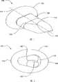
图1是根据本发明的植入体的实施例的透视图,其具有间隔器、分离导引器和具有椭圆截面的翼状物。Figure 1 is a perspective view of an embodiment of an implant according to the invention with a spacer, a separation guide and wings with an elliptical cross-section.
图2是图1所示植入体的端视图。Figure 2 is an end view of the implant shown in Figure 1 .
图3是另一根据本发明的植入体的实施例的透视图,其具有泪珠形截面的翼状物。Figure 3 is a perspective view of another embodiment of an implant according to the present invention having wings of teardrop shaped cross-section.
图4是与图3所示的植入体一起使用的第二翼状物的端视图。4 is an end view of a second wing for use with the implant shown in FIG. 3 .
图5是根据本发明的植入体的实施例的透视图,其具有可旋转间隔器和具有椭圆形截面的翼状物。Figure 5 is a perspective view of an embodiment of an implant according to the present invention having a rotatable spacer and wings having an oval cross-section.
图6是根据本发明的植入体的实施例的透视图,其具有带有两个泪珠形截面的翼状物的可旋转间隔器。Figure 6 is a perspective view of an embodiment of an implant according to the present invention having a rotatable spacer with two wings of teardrop shaped cross-section.
图7示出从末端进行观察的图6所示的植入体的旋转轴。Figure 7 shows the axis of rotation of the implant shown in Figure 6 viewed from the tip.
图8是根据本发明的植入体的实施例的透视图,其具有从后端截短的翼状物。Figure 8 is a perspective view of an embodiment of an implant according to the present invention having wings truncated from the posterior end.
图9A是图8所示的植入体的端视图。9A is an end view of the implant shown in FIG. 8 .
图9B是与图9A所示的植入体一起使用的截短的第二翼状物。Figure 9B is a truncated second wing for use with the implant shown in Figure 9A.
图10是根据本发明的植入体的实施例的平面图,其中一螺钉用于固定第二翼状物至间隔器。Figure 10 is a plan view of an embodiment of an implant according to the present invention with a screw used to secure the second wing to the spacer.
图11是图10所示的第二翼状物的透视图。FIG. 11 is a perspective view of the second wing shown in FIG. 10 .
图12是图10所示的植入体的透视图。FIG. 12 is a perspective view of the implant shown in FIG. 10 .
图13A是与本发明的植入体的一些实施例一起使用的第二翼状物的主视图,其具有用于固定第二翼状物到植入体的活动铰链机构。Figure 13A is a front view of a second wing for use with some embodiments of the implants of the present invention, having a living hinge mechanism for securing the second wing to the implant.
图13B是图13A所示的第二翼状物的侧截面视图。Figure 13B is a side cross-sectional view of the second wing shown in Figure 13A.
图14A是与图13A和13B所示的第二翼状物一起使用的植入体的实施例的平面图。Figure 14A is a plan view of an embodiment of an implant for use with the second wing shown in Figures 13A and 13B.
图14B是13A和13B所示的第二翼状物的主视图。Figure 14B is a front view of the second wing shown in Figures 13A and 13B.
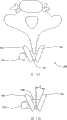
图15A是定位在相邻颈椎的椎突之间的根据本发明的植入体的实施例的俯视图。Figure 15A is a top view of an embodiment of an implant according to the present invention positioned between the vertebral processes of adjacent cervical vertebrae.
图15B是图15A所示的植入体的俯视图,其示出了翼状物的定向。15B is a top view of the implant shown in FIG. 15A showing the orientation of the wings.
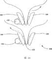
图16是图15A和15B所示的本发明的这两个植入体的俯视图,其定位在颈椎中。Figure 16 is a top view of the two implants of the present invention shown in Figures 15A and 15B, positioned in the cervical spine.
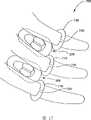
图17是本发明的定位在颈椎中的两个植入体的侧视图,其具有在椎突的近端的止动器或保持器。Figure 17 is a side view of two implants of the present invention positioned in the cervical spine with stops or retainers at the proximal ends of the vertebral processes.
图18A是根据本发明的植入体的替换实施例的透视图,其具有第一翼状物和第二翼状物,该第一翼状物和第二翼状物在将植入体设置在相邻椎突之间后可以展开。18A is a perspective view of an alternative embodiment of an implant according to the present invention having a first wing and a second wing after positioning the implant in adjacent vertebrae. It can be unfolded after the protrusion.
图18B是处于展开构型的图18B所示的植入体透视图。Figure 18B is a perspective view of the implant shown in Figure 18B in an expanded configuration.
图19A是定位在相邻椎突之间处于非展开构型的图18A和18B所示的植入体的后视图。19A is a posterior view of the implant shown in FIGS. 18A and 18B positioned between adjacent vertebral processes in an undeployed configuration.
图19B是定位在相邻椎突之间处于展开构型的图18A和18B所示的植入体的后视图。19B is a posterior view of the implant shown in FIGS. 18A and 18B positioned between adjacent vertebral processes in the deployed configuration.
图20A是另一根据本发明的植入体的实施例的透视图,其具有第一翼状物和第二翼状物,该第一翼状物和第二翼状物在将植入体设置在相邻椎突之间后可以展开。20A is a perspective view of another embodiment of an implant according to the present invention having a first wing and a second wing when the implant is positioned adjacent Between the vertebral processes can be expanded.
图20B是处于展开构型的图20A所示的植入体的透视图。Figure 20B is a perspective view of the implant shown in Figure 20A in an expanded configuration.
图21是定位在相邻椎突之间处于展开构型的图20A和20B所示的植入体的后视图。21 is a posterior view of the implant shown in FIGS. 20A and 20B positioned between adjacent vertebral processes in the deployed configuration.
图22A是根据本发明的植入体的替换实施例的透视图,其具有第一翼状物和第二翼状物,该第一翼状物和第二翼状物在将植入体设置在相邻椎突之间后可以展开。22A is a perspective view of an alternative embodiment of an implant according to the present invention having a first wing and a second wing when the implant is placed in adjacent vertebrae. It can be unfolded after the protrusion.
图22B是处于部分展开构型的图22A所示的植入体的透视图。Figure 22B is a perspective view of the implant shown in Figure 22A in a partially deployed configuration.
图22C是处于完全展开构型的图22A所示的植入体的透视图。Figure 22C is a perspective view of the implant shown in Figure 22A in a fully deployed configuration.
图23A是图22A所示的植入体的透视图,其包括一套管,该植入体被布置在套管里以插入相邻椎突之间的期望位置。23A is a perspective view of the implant shown in FIG. 22A including a sleeve within which the implant is disposed for insertion between adjacent vertebral processes at a desired location.
图23B是处于部分展开构型的图23A所示的植入体的透视图。Figure 23B is a perspective view of the implant shown in Figure 23A in a partially deployed configuration.
图23C是示出由绳索连接的铰链结构的图23A所示的植入体的放大透视图。Fig. 23C is an enlarged perspective view of the implant shown in Fig. 23A showing the hinge structure connected by the cables.
图24示出植入根据本发明的图1-17所示的椎间植入体的方法的实施例。Figure 24 shows an embodiment of a method of implanting the intervertebral implant shown in Figures 1-17 according to the present invention.
图25示出植入根据本发明的具有可展开的第一和第二翼状物的图18A-21所示的椎间植入体的方法的实施例。25 illustrates an embodiment of a method of implanting the intervertebral implant shown in FIGS. 18A-21 having deployable first and second wings in accordance with the present invention.
图26示出通过插入在相邻椎突之间的套管植入根据本发明的图22A-23B所示的具有可展开的第一和第二翼状物的椎间植入体的方法的替换实施例。Figure 26 shows an alternative method of implanting the intervertebral implant shown in Figures 22A-23B with deployable first and second wings according to the present invention through a cannula inserted between adjacent vertebral processes Example.
具体实施方式Detailed ways
图1和图2示出根据本发明的实施例的植入体100。植入体100包括翼状物130、间隔器120和引入组织扩张器(在此及后也称作分离导引器)分离导引器110。在该特定实施例中,分离导引器110为楔形,也就是,植入体具有从植入体的远端102到区域104的逐渐扩大的截面,在区域104处导引器110与间隔器120结合(图中参考是基于椎突之间的植入体的插入点)。这样,当植入体100手术中插入椎突之间时,分离导引器起到使得软组织和椎突分开的功能。可理解的是,为了便于将植入体100插入相邻的颈椎的椎突之间,可将分离导引器110弄尖等。这样做是有利的,为了减少对手术部位的创伤并促进早日愈合,插入技术尽可能地只影响到一点骨头和周围组织或韧带,防止正常解剖的不稳定。在图1和图2的实施例中,不需要移去任何椎突的骨头,并且不需要从人体切断或移去与椎突直接相连的韧带和组织。例如,不必切断项韧带(棘上韧带),其部分地衬垫上颈椎的椎突。1 and 2 illustrate an
从图1-3可看出,间隔器120的垂直于植入体100的纵向轴125的截面可为泪珠形状。以这种方式,间隔器120的形状可大致与相邻椎突之间的楔形空间或楔形空间的一部分相一致,其中植入体100定位在所述椎突中。在其它实施例中,间隔器120可具有替换形状例如圆形、楔形、椭圆形、卵形、足球形和具有圆边角的矩形和其它形状,其在本发明的精神和范围之中。间隔器120的形状可针对特定患者选定,使得医生可尽可能接近椎突表面的前部地定位植入体100。为间隔器120所选的形状可影响植入体100和待经受分离的椎突的接触表面积。增加植入体100和椎突之间的接触表面积可分散椎架和植入体100之间的力和负载。As can be seen from FIGS. 1-3 , the
从图1和图2可看出,在一实施例中的翼状物130的垂直于纵向轴125的截面可为椭圆形状的。翼状物130的尺寸可比间隔器120的尺寸大,尤其是沿着中心轴,并可限制或阻挡植入体100在沿着纵向轴125的插入方向的侧向位移。如图3的实施例所示,翼状物130还可替换地具有其它截面形状,例如泪珠形、楔形、圆形、卵形、足球形和圆边角的矩形以及其它形状,其都在本发明的精神和范围之内。翼状物130具有前部138和后部136。As can be seen from FIGS. 1 and 2 , the
在其它实施例中,植入体100可包括两个翼状物,其第二翼状物160(如图4所示)与分离导引器110、间隔器120和第一翼状物130分开。第二翼状物160可连接至间隔器120的远端。第二翼状物160,类似于第一翼状物130,可限制或阻挡植入体100的侧向位移,但是沿着纵向轴125的反向插入方向的位移也被限制或阻挡。当第一翼状物130和第二翼状物160都与植入体100相连并且植入体100定位在相邻椎突之间时,部分椎突可被夹在第一翼状物130和第二翼状物160之间,从而限制沿着纵向轴125的任何位移。In other embodiments, the
从图4可看出,第二翼状物160的截面可为泪珠形状的。第二翼状物160的宽端166是后端,第二翼状物160的窄端168是前端。然而,与第一翼状物130不同,开口164限定在第二翼状物160中,开口164至少部分地由唇状物162限定,从而允许第二翼状物160通过分离导引器110接触并连接间隔器120。一旦第二翼状物160得以适当地定位,第二翼状物160可固定至间隔器120。在植入体100被定位在椎突之间之后,第二翼状物160可与植入体相连。As can be seen from FIG. 4 , the cross-section of the
可理解的是,植入体可制造为两块。第一块可包括第一翼状物130、间隔器120和分离导引器110。第二块可包括第二翼状物160。每一块可使用本领域已知的技术(例如机加工、模制和挤压成型)进行制造。每一块,如下面将要更加全面描述,可由与患者身体生物相容的材料制成。植入体可形成为具有多块,并且各块适当地接合在一起,或者,植入体可形成为一个整体或者结合在一起成为一个整体。It will be appreciated that the implant may be manufactured in two pieces. The first piece may include the
图5-7示出根据本发明的植入体的其它实施例。在这些实施例中,间隔器220可绕纵向轴225相对于第一翼状物130或者在使用两个翼状物时相对于第一翼状物130和第二翼状物160而旋转。间隔器220相对于分离导引器110可为可旋转的或固定的。在间隔器220相对于分离导引器110是可旋转的场合,间隔器220可包括孔222和轴224,其中孔222长度为纵向轴225的长度,轴224穿过孔222并连接分离导引器110和第一翼状物130。尽可能靠近椎体地定位在此所教导的任何植入体是有利的。当在植入过程中植入体200被插入并定位时,可旋转间隔器220可旋转以适应于或安放在相邻椎突之间,使得平均起来间隔器220和椎突之间的接触表面积可增加超过固定间隔器120和椎突之间的接触表面积。这样,可旋转间隔器220可改善独立于翼状物130、第二翼状物160的间隔器220相对于椎突的定位。图6的实施例包括泪珠形状的第一翼状物130和泪珠形状的第二翼状物160,泪珠形状的第二翼状物160类似于图3的实施例中描述的第二翼状物160。如下所述,图3和图6中的翼状物130、160的形状是这样的以使得植入体100、200适应颈椎沿其轴的扭动,例如,当患者的头部从一侧转向另一侧时。5-7 show other embodiments of implants according to the invention. In these embodiments, the
图8是一透视图,图9A是根据本发明的植入体的另一实施例的端视图,其中泪珠形第一翼状物330的后部336被截去了,使得第一翼状物330在形状上更加卵形。在这种构型中,第一翼状物330的前部138可比第一翼状物330的被截去的后部336长。如前面的实施例,间隔器120也可替换地为一可旋转的间隔器,而非一固定的间隔器。图9B示出用于这种植入体300的第二翼状物360,该第二翼状物360具有截去的后部366。第一和第二翼状物330、60的后部336、366的截去可降低具有这种定位在颈椎的相邻对的椎突之间的第一和第二翼状物330、360的植入体300的干涉的可能性,例如颈椎五和六之间的植入体,颈椎六和七之间的植入体。在颈部的旋转过程中,椎突类似于剪刀运动一样地运动通过彼此。每一颈椎可相对于下一相邻的颈椎在约6°-12°的大致范围内转动。此外,颈部的约50%的旋转运动是通过上面两个颈椎完成的。这样,这种装置可适应颈部的转动,而没有相邻装置之间的彼此干涉。8 is a perspective view, and FIG. 9A is an end view of another embodiment of an implant according to the present invention, wherein the rear portion 336 of the teardrop-shaped
对于前面的具有第一和第二翼状物130、160的实施例,第二翼状物160可设计为干涉配合到间隔器120上(如果间隔器是固定的)或者与间隔器120相邻的分离导引器110部分上(如果间隔器是可旋转的)。在第二翼状物160是干涉配合的场合,没有额外的附加装置来相对于植入体的其余部分固定第二翼状物160。或者,各种紧固件可用于相对于植入体的其余部分固定第二翼状物。例如,图10-12示出了包括泪珠形第二翼状物460的植入体400的实施例,该第二翼状物460具有穿过第二翼状物460的后端的唇状物461的孔463。当第二翼状物460通过手术插入进入相对于植入体400的其余部分的位置时,孔463对准间隔器120上的相应孔440。螺钉442可在从后部到前部的方向穿过对准的孔463、440以固定第二翼状物460到间隔器120。从后部到前部的插入方向具有螺钉442,螺钉442沿着基本垂直于纵向轴125的方向接合孔463、440和植入体400的其余部分。当需要用手术来使用螺钉442以固定第二翼状物460至植入体400的其余部分时,该方向是最方便的。其它使用插入间隔器120上的相应孔463、440和第二翼状物460的部件的固定机构是在本发明的精神之内。应理解的是,可旋转间隔器220也可通过这种装置调节。使用可旋转间隔器220,第二翼状物460可固定至位于与可旋转间隔器220相邻的分离导引器110的部分。As with the previous embodiment having first and
图13A-14B示出另一实施例500,其中第二翼状物560通过一包括柔性铰链565的机构固定至间隔器120,突起物561在与由部分第二翼状物560限定的开口564的唇状物562相邻的铰链565的末端之上。固定机构也包含在间隔器120上的凹口540,其中凹口540容纳在柔性铰链565末端上的突起物561。在手术过程中,在插入分离导引器110、间隔器120和第一翼状物130之后,第二翼状物560由分离导引器110和间隔器120接收。由于第二翼状物560被间隔器120接收,活动铰链565及其突起物561偏斜直到突起物561接触并与间隔器120中的凹口540结合,从而固定第二翼状物560至间隔器120。再者,在间隔器可旋转的实施例中,凹口540位于与可旋转间隔器220相邻的分离导引器110的末端。对于活动铰链565,该铰链在优选的实施例中与第二翼状物560一起形成,并以这种方式设计,使得其可随着铰链565被推过分离导引器110和间隔器120而弯曲,进而允许突起物561放置到凹口540中。或者,可理解为,凹口540可存在于第二翼状物560中,柔性铰链565和突起物561可存在于间隔器120上,以便将第二翼状物560配合到间隔器120。再或者,柔性铰链565可由柔性突起替换,该柔性突起可弯曲与在间隔器120中具有凹口540的实施例中或在第二翼状物560中具有凹口540的实施例中的凹口540接合。本领域普通技术人员将认识到无数不同的方法,借此第二翼状物可与植入体配合。FIGS. 13A-14B show another
图15A-16示出植入体600的实施例,其中第一翼状物630和第二翼状物660的前端从间隔器120向外张开一定角度并彼此分开。颈部椎突自身从上面观察为楔形。第一翼状物630和第二翼状物660向外展开,使得植入体600可大致与椎突的楔形一致,从而允许植入体600定位在尽可能靠近椎骨的椎体,在椎体处椎骨的负载被支撑。第一和第二翼状物630、660相对于间隔器定位,不管间隔器是固定间隔器120还是可旋转间隔器220,因此随着翼状物接近椎骨的椎体时翼状物展开。图15B是图15A的植入体600从接近椎突的地方移去后的俯视图。第一翼状物630相对于垂直于纵向轴(在此也可称为对称平面)的沿椎突的轴一定角度对准。在一实施例中,该角度为约30°,然而,角度θ的范围可为约15°-45°,在其它实施例中,在该范围之外的角度是期望的并是根据本发明的。同样地,第二翼状物660可沿类似地但相反地相对于对称平面的角度变化范围对准。15A-16 illustrate an embodiment of an
如上参考图4所述,第二翼状物660限定一唇形轮廓的开口。显然,该唇状物可相对于第二翼状物660的其余部分一定角度设置,使得当唇状物被推入与间隔器120接触时,第二翼状物660具有相对于间隔器120的期望角度。如上所述,存在不同的固定第二翼状物660到间隔器120上的方法。图15A示出一放置在相邻颈椎的椎突之间的这种植入体600的俯视图。图16是示出具有展开的翼状物630、660的双层分离植入体600的俯视图。As described above with reference to FIG. 4 , the second wing 660 defines a lip-shaped opening. Obviously, the lip can be angled relative to the rest of the second wing 660 so that when the lip is pushed into contact with the
根据本发明的系统和方法可包括可以与本发明的植入体结合使用的装置。图17示出一种止动器(在此也可称为“保持器”)656,其是柔性生物相容材料的环状物,该环状物可围绕相邻颈椎的椎突定位并位于植入体600后部。保持器656可防止植入体的后向位移。在一实施例中,保持器可包括具有狭缝658的环状物。保持器656可被弹开一些,使得保持器656可配合在椎突末端上,进而允许一起弹回以为了固定在椎突的一个位置。为了防止植入体600在后向的运动,保持器656可作为间隔器120的挡块。Systems and methods according to the present invention may include devices that may be used in conjunction with implants of the present invention. Figure 17 shows a stopper (which may also be referred to herein as a "retainer") 656, which is a ring of flexible biocompatible material that can be positioned around the vertebral processes of adjacent cervical vertebrae and positioned at
具有可展开翼状物的植入体Implants with deployable wings
在其它实施例中,根据本发明的植入体可包括具有第一构型(如图18A所示)和第二展开的构型(如图18B所示)的“火柴盒”状的结构。安置在第一构型中,该植入体700可具有厚度大致均匀的基本上平坦的外廓。所述均匀的厚度接近植入体700的间隔器720的厚度。植入体700可包括在植入体近端的分离导引器710,该分离导引器710具有稍稍圆形或锥形的形状以穿过和/或分离相邻椎突之间的间隔。植入体700可还包括多个铰链结构750-757,该铰链结构750-757为折叠起来的以使得有助于基本平坦的外廓。铰链结构750-757是与间隔器720枢轴连接并从间隔器720的两侧延伸。如图18A所示,支撑结构722从间隔器720向着植入体700的远端延伸。杆715(或者一些其它机构,例如凸台)可与植入体700的近端相连并延伸通过铰链结构750-753,通过间隔器720,并通过支撑结构722,使得杆715是可接近的。In other embodiments, implants according to the present invention may comprise a "matchbox" like structure having a first configuration (as shown in Figure 18A) and a second deployed configuration (as shown in Figure 18B). Positioned in the first configuration, the
参照图18B,一旦植入体700被如期望地定位在相邻椎突之间,杆715可与沿着纵向轴725的插入方向相反的方向拉拽,使得铰链结构750-757向外展开以形成第一翼状物730和第二翼状物760,在第一翼状物730和第二翼状物760之间设置间隔器720和椎突的一部分。由于铰链结构750-757向外展开,第一和第二翼状物730、760的高度从与间隔器720的厚度大致相同的高度增加到一使得当第一和第二翼状物730、760定位在相邻椎突之间时其可限制或阻挡植入体700沿纵向轴725的运动的高度。可看出,第二翼状物760包括四个铰链结构750-753:由铰链连接至上面第二结构752的上面第一结构750,和由铰链连接至下面第二结构753的下面第一结构751。铰链结构750-753向外转动以形成第二翼状物的上端762和第二翼状物的下端764。同样地,第一翼状物730包括四个铰链结构754-757:由铰链连接至上面第二结构756的上面第一结构754,和由铰链连接至下面第二结构757的下面第一结构755。然而,不同于第二翼状物760,第一翼状物730是(有效地)由支撑结构722对截开,使得第一翼状物730包括四个小翼731-734。铰链结构754-757向外转动以形成第一翼状物的上面小翼731、732和第一翼状物的下面小翼733、734。18B, once the
如上所述,支撑结构722从间隔器720向着植入体700的远端延伸。间隔器720和支撑结构722包括一孔或其它腔体,杆715可穿过该孔或腔体。当拽拉杆715通过孔时,施加阻力到支撑结构722上可将间隔器720固定就位于椎突之间。由于杆715被拽拉通过孔,与杆715的近端连接的铰链结构752、753被用杆715拽拉。由于杆715被拽拉通过间隔器720,铰链结构752、753被向着间隔器720拽拉。铰链结构750-753向外转动以调整杆715和间隔器720之间的相对运动。相应地,第二翼状物760已经得以满意地展开。As noted above,
第一翼状物730的铰链结构756、757可通过当拽拉间隔器720(通过支撑结构722)时施加阻力到756、757或者通过向着间隔器720推铰链结构756、757而使得第一翼状物730展开。阻力或推力可由第二止动器784施加,第二止动器784可绕支撑结构722配合并可干涉配合或者可选择地用支撑结构722固定。当第二止动器784被沿着纵向轴725推动时,沿着支撑结构722,铰链结构754-747向外转动以调整第二止动器784和间隔器720之间的相对运动。相应地,第一翼状物730已经得以满意地展开。The
图19A和19B是定位在相邻椎突2、4之间的植入体700的后视图,其示出展开椎突2、4之间的植入体700的方法的实施例。植入体700可被定位,使得植入体700的分离导引器710设置在椎突2、4之间的空间。然后,植入体700可被推入椎突2、4之间,使得间隔器720如所期望地定位。植入体700的基本平坦的外廓可通过减少植入过程中可阻止植入体700运动的潜在阻碍表面,从而使得间隔器720的定位更加容易。第二翼状物760和第一翼状物730然后可展开以限制植入体700的运动。为了展开第二翼状物760,杆715在逆着沿纵向轴725插入方向的方向拽拉。第二翼状物的上端762和下端764如上所述地向外延伸。一旦第二翼状物760展开,杆715可相对间隔器720固定就位。这可通过使用多种不同的机构实现。例如,如所示出的,第一止动器782可干涉配合至杆715并沿杆715靠着支撑结构722定位。由于第一止动器782和杆715之间的摩擦配合,第一止动器782可夹持杆715,从而防止杆715通过第一止动器782和支撑结构722之间的干涉运动穿过支撑结构722的孔。在其它实施例中,可使用一些其它机构,例如销(例如开口销)、闭锁系统等。本领域普通技术人员将认识到用于将杆715相对于间隔器720固定就位的许多不同机构。上面第二结构756和下面第二结构757可通过使用如上所述的第二止动器784向着间隔器720在沿纵向轴725的插入方向推入,从而导致上面小翼731、732和下面小翼733、734向外延伸形成第一翼状物730。一旦第一翼状物730展开,铰链结构754-757可通过使用第二止动器784或一些其它机构而固定就位。第二止动器784可靠摩擦配合或销夹持支撑结构722,并阻止铰链结构754-757的运动,从而防止折叠。如上所述,本领域普通技术人员将认识到用于固定第一翼状物730在展开位置的多种不同机构。利用展开的第一翼状物730和第二翼状物760,植入体700沿纵向轴725的运动可得到限制或阻挡,从而阻止植入体700的不期望的位移。19A and 19B are posterior views of an
应注意到,对于上面参照图18A-21所述的植入体,杆715可选择性地进行修整或部分分离以降低在患者脊椎中容纳植入体700、800所需的空间。例如,杆715的结构可在接近杆71 5的远端倾斜或变细,从而允许当第一和第二翼状物730、760、830、860展开并且杆715固定就位时杆715得以折断。在其它实施例中,在第一和第二翼状物730、760、830、860展开并且杆715固定就位后,可使用工具(未示出)截断杆715。此外,杆715并不必要地包括刚性结构,相反替换地可包括绳索、弹簧或类似柔性结构,其可放置在拉紧状态以保持第二翼状物760、860和/或第一翼状物730、830在展开位置。It should be noted that, as with the implants described above with reference to Figures 18A-21, the
参照图20A和20B,示出了另一根据本发明的植入体800的实施例。在该实施例中,柔性带890可连接在多副铰链结构(也就是,850和852,851和853,854和856,855和857)之间。柔性带890可限制铰链结构850-857的相对运动,使得当第一翼状物830和第二翼状物860全部展开时第一翼状物830和第二翼状物860具有增强的刚度。植入体800并不需要包括前面实施例中的支撑结构722。可施加阻力到铰链结构856、857,使得当杆715逆着沿纵向轴825的插入方向的方向拽拉时,该阻力导致铰链结构854-857向外延展以形成第一翼状物830。由于铰链结构854-857向外延展,对着铰链连接的柔性带890打开。一旦铰链结构854-857达到最大延展量,柔性带890拉紧并阻止进一步延展,将第一翼状物830锁闭就位。柔性带890可提供具有足够刚度的第一翼状物830以阻止间隔器720的运动,使得随着杆715进一步拽拉,杆715穿过间隔器720,并且与杆715连接的铰链结构852、853向着间隔器720拽拉。由于与杆715连接的铰链结构852、853向着间隔器720拽拉,所有的铰链结构850-853向外延展以展开第二翼状物860。对着铰链连接的柔性带890打开。一旦铰链结构854-857达到最大延展量,柔性带890拉紧并阻止进一步延展,从而将第一翼状物830锁闭就位。止动器882(或一些其它机构,例如销)可固定到杆715上以产生止动器882和第一翼状物830的铰链结构832、834之间的干涉,从而阻止杆715的运动。Referring to Figures 20A and 20B, another embodiment of an
柔性带890可由生物相容材料制成。在一实施例中,柔性带890可由编织聚酯缝合材料制成。编织聚酯缝合材料包括例如Ethibond、Ethiflex、Mersilene和Dacron,并且其为不可吸收的,具有高张力强度、低组织抗性和改进处理。在其它实施例中,柔性带890可由不锈钢(也就是,手术钢)制成,其可例如织为带。在其它实施例中,柔性带890可由一些其它具有类似属性的材料(或材料的组合)制成。The
图21是定位在相邻椎突2、4之间的植入体800的后视图,其示出展开椎突2、4之间的植入体800的方法的实施例。第一翼状物830可展开以限制植入体800相对于椎突2、4的运动。为了展开第一翼状物830,杆715可被保持固定就位或在逆着沿纵向轴825的插入方向的方向推动,同时施加力到第一翼状物830的铰链结构854-857(图20A),从而导致第一翼状物的上端832和下端834从杆715向外延伸,从而展开第一翼状物830。杆715可在逆着插入方向的方向进一步推动,使得枢轴连接包括分离导引器710的铰链结构852、853的杆715的近端向着间隔器720拽拉,从而导致间隔器的上端862和下端864从杆715向外延展。一旦第二翼状物860和第一翼状物830展开,杆715可相对于间隔器720固定就位。如上,这可通过使用多种不同机构实现。例如,如所示出的,止动器882可干涉配合至杆715并靠着第一翼状物830沿杆715定位。第一止动器882可夹持杆715,从而防止杆715被第一止动器882和杆715之间的摩擦配合移动。在其它实施例中,可使用一些其它机构,例如销(例如开口销)、锁闭系统等。本领域普通技术人员将认识到用于将杆715相对间隔器720固定就位的许多不同机构。利用展开的第一翼状物830和第二翼状物860,植入体800沿纵向轴825的运动可得以限制或阻止,从而阻止植入体800的不期望的运动。21 is a posterior view of an
参照图22A和22B,在其它实施例中,根据本发明的植入体可包括具有圆形的折叠的第一构型和展开的第二构型的“火柴盒”状的结构。处于第一构型中,该植入体900可具有允许植入体900更自然地插入通过套管的形状。如所示出的,这种形状包括基本上圆形的截面,尽管在一些实施例中植入体可具有卵形或椭圆形截面,从而允许采用通常可适应相邻椎突之间的空间的间隔器形状。然而,将认识到,具有圆形截面的植入体900可最为充分地利用套管的空间,其中套管包括圆形截面;因此,当医生期望最小化插入手术位置的套管的直径时,可优选采用具有圆形截面的植入体900。Referring to Figures 22A and 22B, in other embodiments, an implant according to the present invention may comprise a "matchbox" like structure having a circular folded first configuration and an expanded second configuration. In the first configuration, the
第一构型中的植入体900的截面大体在沿着植入体的长度方向,具有与植入体900的间隔器920的厚度基本一致的直径。植入体900可包括在植入体900的近端的分离导引器910,分离导引器910具有圆形(如所示出)或锥形的形状以穿过和/或分离相邻椎突之间的空间。然而,在使用套管将植入体传递至手术位置的地方,植入体900可选择性地包括在近端的分离导引器910。手术位置以及关联组织和结构可用套管分离和再定位,从而允许植入体900基本无障碍地通向手术位置。在这种情况下,分离导引器910可不是必需的。The cross-section of the
植入体900还可包括多个铰链结构950-957,铰链结构950-957可折叠起来以使得便于基本上折叠起来的外廓。铰链结构950-957枢轴连接间隔器920并从间隔器920的两侧延展。杆915(或者一些其它机构,例如凸台)可与植入体900的近端连接并延伸通过铰链结构950-953,并通过间隔器920,使得杆915对医生是可接近的。
参照图22B和22C,一旦植入体900如所希望地定位在相邻椎突之间,杆915可在沿纵向轴925的逆着插入方向的方向拽拉,使得铰链结构950-957向外折叠以形成第一翼状物930和第二翼状物960,在第一翼状物930和第二翼状物960之间安置间隔器920和部分椎突。由于铰链结构950-957向外折叠,第一和第二翼状物930、960的高度从大致与间隔器920的厚度相同的高度增加到一使得第一和第二翼状物930、960可在当其定位在相邻椎突之间时限制或阻止植入体900沿着纵向轴925的运动的高度。可看出,第二翼状物960包括四个铰链结构950-953:由铰链连接至上面第二结构952的上面第一结构950、由铰链连接至下面第二结构953的下面第一结构951。铰链结构950-953向外转动以形成第二翼状物的上端962和下端964。同样,第一翼状物930包括四个铰链结构954-957:由铰链连接至上面第二结构956的上面第一结构954、由铰链连接至下面第二结构957的下面第一结构955。Referring to Figures 22B and 22C, once the
如上参照图18A和18B所述的实施例包括从间隔器720延伸的支撑结构722。同样,支撑结构可选择性地从套管传递的植入体900的间隔器920延伸。然而,在套管995自身(参照图23B)防止第一翼状物930在第二翼状物960的展开过程中展开的地方,这种结构并不是必需的。参照图23A和23B,一旦套管被定位在手术位置,植入体900可被推动穿过套管,使得铰链结构950-953离开套管。然后杆915可在逆着沿纵向轴925的方向(相对于插入方向)推入以展开第二翼状物960。由于杆915被拽拉通过间隔器920,铰链结构952、953被向着间隔器920拽拉。铰链结构950-953向外转动以调整杆915和间隔器920之间的相对运动。相应地,第二翼状物960已经得以满意地展开。The embodiment described above with reference to FIGS. 18A and 18B includes a
一旦第二翼状物960得以展开,套管995可从手术位置收回,从而允许第一翼状物930的铰链结构956、957通过向着间隔器920推动铰链结构956、957而展开。所述推动可由止动器982施加,该止动器982可绕杆915配合并可干涉配合或选择性地与杆915固定。由于止动器982被沿着纵向轴925推动,沿着杆915,铰链结构954-957向外转动以接纳止动器982和间隔器920之间的相对运动。相应地,第一翼状物930已经得以满意地展开。Once the
一旦第二翼状物960和第一翼状物930得以展开,杆915可相对间隔器920固定就位。如上,这可通过很多不同机构实现。例如,如所示出的止动器982可干涉配合到杆915并靠着第一翼状物930沿杆915定位。止动器982可夹持杆915,从而防止杆915通过止动器982和杆915之间的摩擦配合移动。在其它实施例中,可使用一些其它机构,例如销(例如开口销)、锁闭系统等。本领域普通技术人员将认识到用于相对间隔器920将杆915固定就位的许多不同机构。随着第一翼状物930和第二翼状物960展开,植入体900沿纵向轴925的运动可得以限制或阻止,从而阻止植入体900的不期望的位移。Once the
应注意到,对于如上参照图22A-23B所述的植入体,杆915可选择性地进行修整或部分分离以减少患者脊椎中容纳植入体900所需的空间。例如,杆915的结构可在接近杆915的远端倾斜或变细,从而允许当第一和第二翼状物930、960展开并且杆915固定就位时截断。在其它实施例中,可在第一和第二翼状物930、960展开并且杆915固定就位后使用工具(未示出)截断杆915。此外,杆915并不必要地包括刚性结构,相反替换地可包括绳索、弹簧或类似柔性结构,其可拉紧以将第二翼状物960和/或第一翼状物930保持在展开位置。It should be noted that, as with the implants described above with reference to Figures 22A-23B, the
参照图22B、22C和23B,植入体900被示出具有可操作连接的“铰链”结构950-957。该结构可以以任何允许相对运动的方式铰接。例如,该结构可通过柔性带的方式铰接,例如如上参照图20B所描述的。或者,该结构可通过一些其它技术铰接。例如,参照图24C,一个或一对绳索996可连接多副铰链结构,使得相对运动得以受限,从而允许铰链运动,同时阻止结构的分离。在其它一些实施例中,可采用一些其它机构以限定铰链结构950-957的运动范围。本领域技术人员将认识到用于限定两个机械部件的运动范围的许多不同技术。Referring to Figures 22B, 22C and 23B,
如利用上面的柔性带890,绳索996可由生物相容材料制成。在一实施例中,绳索996可由编织聚酯缝合材料制成。编织聚酯缝合材料包括例如Ethibond、Ethiflex、Mersilene和Dacron,并且其为不可吸收的,具有高张力强度、低组织反应性和改进处理。在其它实施例中,绳索996可由不锈钢(也就是,手术钢)制成,其可例如织为带。在其它实施例中,绳索996可由一些其它具有类似属性的材料(或材料的组合)制成。As with
用于本发明的植入体的材料Materials for the implants of the present invention
在一些实施例中,植入体可由医用级金属例如钛、不锈钢、钴铬及其合金,或其它具有类似高强度和生物相容属性的适合的植入体材料制成。此外,植入体可至少部分地由形状记忆金属例如钛和镍组合的镍钛诺制成。这些材料是典型地不透射线的,并在X光成像和其它类型的成像中出现。根据本发明的植入体和/或其部分也可由一些柔性和/或可变形材料制成。在一些实施例中,植入体和/或其部分可全部或部分地由医用级生物相容聚合物、共聚物、混合物和聚合物组合物制成。共聚物是从超过一类单体衍生的聚合物。聚合物组合物是两种或更多材料的异相组合,其中其组分是不可混合的,因此呈现彼此之间的交接面。聚合物混合物是两种或多种不同类的聚合物的宏观均质混合物。很多聚合物、共聚物、混合物和聚合物组合物是可透射线的,在X光成像或其它类型的成像中并不显现。包括这种材料的植入体在成像下可比使用包括完全不透射线材料的植入体提供给医生更少的脊柱观察障碍。但是,该植入体并不必要地包括任何可透射线材料。In some embodiments, the implant may be made of medical grade metals such as titanium, stainless steel, cobalt chromium and alloys thereof, or other suitable implant materials with similar high strength and biocompatible properties. In addition, the implant may be at least partially fabricated from a shape memory metal such as nitinol in combination of titanium and nickel. These materials are typically radiopaque and show up in X-ray imaging and other types of imaging. Implants and/or parts thereof according to the invention may also be made of some flexible and/or deformable materials. In some embodiments, implants and/or portions thereof may be made in whole or in part from medical grade biocompatible polymers, copolymers, blends, and polymer compositions. Copolymers are polymers derived from more than one type of monomer. A polymer composition is a heterogeneous combination of two or more materials in which the components are immiscible and thus present an interface between each other. A polymer blend is a macroscopically homogeneous mixture of two or more polymers of different classes. Many polymers, copolymers, blends and polymer compositions are radiolucent and do not show up in x-ray imaging or other types of imaging. Implants comprising such materials may provide physicians with fewer obstacles to viewing the spine under imaging than using implants comprising fully radiopaque materials. However, the implant does not necessarily include any radiolucent material.
一组生物相容材料是聚芳基酯酮,其具有数个成员,包括聚醚醚酮(PEEK)和聚醚酮酮(PEKK)。PEEK被证明是耐用的植入体材料,并达到生物相容的标准。医用PEEK可从英国的兰开夏(Lancashire)的Victrex公司的产品PEEK-OPTIMA获得。医用级PEKK可从Oxford Performance Material的产品OXPEKK获得,也可从CoorsTek的产品BioPEKK获得。这些医用级材料也可作为加强聚合物树脂获得,该加强树脂甚至展示更好的材料强度。在一实施例中,植入体可由PEEK 450G制成,其是用于医疗植入的获准的未充填PEEK,可从Victrex获得。这种材料的其它来源包括位于印度的Panoli的Gharda。PEEK 450G具有以下大致属性:One group of biocompatible materials is the polyarylate ketones, which have several members including polyetheretherketone (PEEK) and polyetherketoneketone (PEKK). PEEK is proven to be a durable implant material and meets biocompatible standards. Medical PEEK is available from Victrex, Lancashire, UK under the product PEEK-OPTIMA. Medical grade PEKK is available from Oxford Performance Material as product OXPEKK and from CoorsTek as product BioPEKK. These medical grade materials are also available as reinforced polymer resins that exhibit even better material strength. In one embodiment, the implant can be made from PEEK 450G, which is an approved unfilled PEEK for medical implants, available from Victrex. Other sources of this material include Gharda in Panoli, India. PEEK 450G has the following general properties:
属性 值attribute value
密度 1.3g/ccDensity 1.3g/cc
Rockwell M 99Rockwell M 99
Rockwell R 126Rockwell R 126
张力强度 97MPaTensile Strength 97MPa
弹性模量 3.5GPaElastic modulus 3.5GPa
挠曲模量 4.1GPaFlexural modulus 4.1GPa
PEEK 450G具有适合的物理和机械属性,并适于承载和分散相邻椎突之间的物理负载。植入体和/或其部分可通过挤压、注射、压缩模塑法和/或机加工技术形成。PEEK 450G has suitable physical and mechanical properties and is suitable for carrying and distributing physical loads between adjacent vertebral processes. Implants and/or parts thereof may be formed by extrusion, injection, compression molding and/or machining techniques.
应注意到,所选择的材料也可被充填。充填物可加入到聚合物、共聚物、聚合物混合物或聚合物组合物以加强聚合物材料。充填物加入以改善属性,例如机械、光学和热属性。例如,为了某种用途,例如用于负载承载装置,可加入碳纤维以机械地加强聚合物,从而提高强度。在一些实施例中,其它等级的PEEK是可用的并可期望用于根据本发明的植入体,例如30%的玻璃充填或30%的碳充填等级,只要这些材料用于可植入装置是由FDA,或其它制定规章的机构认可的。相对于未充填的PEEK,玻璃充填PEEK降低延展率并增加PEEK的挠曲模量。所得到的产品对于改善强度、刚度或稳定性已知是理想的。相对于未充填的PEEK,碳充填PEEK是已知的具有提高的压缩强度和刚度和更低的延展率。碳充填PEEK也提供耐磨损和负载承载能力。It should be noted that the material of choice may also be filled. Fillers may be added to polymers, copolymers, polymer blends or polymer compositions to reinforce polymeric materials. Fillers are added to improve properties such as mechanical, optical and thermal properties. For example, carbon fibers can be added to mechanically reinforce the polymer for certain uses, such as load carrying devices, thereby increasing strength. In some embodiments, other grades of PEEK are available and contemplated for use in implants according to the present invention, such as 30% glass-filled or 30% carbon-filled grades, as long as these materials are suitable for use in implantable devices. Recognized by FDA, or other regulatory agency. Glass-filled PEEK reduces elongation and increases PEEK's flexural modulus relative to unfilled PEEK. The resulting products are known to be desirable for improved strength, stiffness or stability. Carbon-filled PEEK is known to have increased compressive strength and stiffness and lower elongation relative to unfilled PEEK. Carbon filled PEEK also provides wear resistance and load carrying capacity.
将认识到,其它适当的类似生物相容热塑或热塑缩聚物材料,其抗疲劳、具有良好的记忆,是可挠曲和/或可弯曲的,具有非常低的湿度吸收和良好的抗磨损和/或抗磨蚀,其都可使用,并不超出本发明的范围。如所提及的,植入体可包括聚醚酮酮(PEKK)。其它可用的材料包括聚醚酮(PEK)、聚醚酮醚酮酮(PEKEKK)、聚醚醚酮酮(PEEKK)和通常的聚芳基醚醚酮。此外,可使用其它聚酮以及其它热塑性塑料。可用于植入体的适当的聚合物的参考资料可参考如下文件,其在此被引用作为参考。这些文件包括:PCT公开WO02/02158A1,日期:2002年1月10日,标题:Bio-CompatiblePolymeric Materials;PCT公开WO02/00275A1,日期:2002年1月3日,标题:Bio-Compatible Polymeric Materials;和PCT公开WO02/00270A1,日期:2002年1月3日,标题:Bio-Compatible Polymeric Materials。其它材料,例如Bionate
如上所述,粘合剂可用生物相容材料制成。在一实施例中,粘合剂可由编织聚酯缝合材料制成。编织聚酯缝合材料包括,例如,Ethibond、Ethiflex、Mersilene和Dacron,并且其是不可吸收的,具有高张力强度、低组织反应和改进处理。在其它实施例中,粘合剂可由不锈钢(也就是手术钢)制成,其可例如植入绳索或织为带。在其它实施例中,粘合剂可由其它具有类似属性的材料(或材料的组合)制成。As noted above, the adhesive can be made of biocompatible materials. In one embodiment, the adhesive may be made from a braided polyester suture material. Woven polyester suture materials include, for example, Ethibond, Ethiflex, Mersilene, and Dacron, and are nonabsorbable, have high tensile strength, low tissue response, and improve handling. In other embodiments, the adhesive may be made of stainless steel (ie, surgical steel), which may be embedded in a cord or woven into a strap, for example. In other embodiments, the adhesive may be made of other materials (or combinations of materials) with similar properties.
可理解的是,根据本发明的实施例可不由柔性材料构建。同样可理解的是,根据本发明的实施例可具有其它尺度。It is understood that embodiments in accordance with the present invention may not be constructed of flexible materials. It is also understood that embodiments according to the invention may have other dimensions.
植入椎间植入体的方法Methods of Inserting Intervertebral Implants
在此公开和教导了将植入体400植入到颈椎中的最小侵入手术方法。在该方法中,如图24所示,优选地将引线80穿引通过定位网状物或导引90,进入植入体接收者的颈部。引线80可用于定位植入体相对于包括椎突的颈椎的放置位置。一旦引线80在影像技术的帮助下得以定位,则在颈部侧面作一切口,使得根据本发明的实施例的植入体可穿过切口并沿约垂直于引线80的直线且向着引线80的末端而被定位在颈部。在一实施例中,植入体可为一尺寸适合的植入体400(也就是,具有不可分离的主体),如图1-17所示,并包括分离导引器110、间隔器120和第一翼状物130。植入体400被插入患者的颈部。优选地在插入过程中,分离导引器110穿过或分离组织而不需要切断组织。A minimally invasive surgical method of implanting
一旦植入体400得以满意地定位,第二翼状物460可选择性地沿着与植入体400被插入的线基本共线的线但是从颈部的相反侧插入。颈部的解剖是使得最为方便并最小侵入以从关于植入体400和第二翼状物460的一侧进入颈部。第二翼状物460是与植入体配对的,并且在这一特定的实施例中,第二翼状物460通过使用紧固件例如螺钉442固定至植入体400。在使用螺钉的地方,螺钉442可通过使用沿着从后到前的与引线80有点平行的线定向的螺钉驱动机构定位。该从后到前的线帮助医生观察和固定第二翼状物460到植入体。第二翼状物460得以定位,使得形成在第二翼状物460的唇状物461中的孔463与植入体400的孔440对齐,如上所述。螺钉442定位在两个孔中,并至少固定至植入体400的孔440。在其它实施例中,第二翼状物可与植入体干涉配合,如上所述,或者使用一些其它机构例如柔性铰链和突起进行固定。Once the
在此公开和教导将植入体700的替换实施例植入颈椎中的最小侵入手术方法。在这种方法中,如图25所示,优选地将引线80插入穿过定位网状物或导引90进入植入体接收物的颈部。引线80可用于定位将植入体700相对于包括椎突的颈椎放置的地方。一旦引线80在影像技术的帮助下得以定位,则在颈部侧作一切口,使得根据本发明的实施例的植入体700可穿过切口并沿约垂直于引线80的直线且向着引线80的末端而被定位在颈部。在一实施例中,植入体700可包括分离导引器710、间隔器720和从间隔器720延伸的杆715以及可展开的第一和第二翼状物730、760。植入体700可具有基本平坦的外廓以易于植入,如上所述。植入体700被插入患者的颈部。优选在插入过程中,分离导引器710穿过或分离组织而不需要切断组织。A minimally invasive surgical method of implanting an alternate embodiment of
一旦植入体700得以满意地定位,第一翼状物730和第二翼状物760可以展开。如上所述,第二翼状物760可通过与沿着纵向轴725的插入方向相反的方向推动杆715而得以展开。由于杆715穿过间隔器720,铰链结构750-753接触间隔器720,扣住杆715并从杆715延伸,二者形成第二翼状物的上端762和下端764。当第二翼状物760得以满意地展开时,杆715可通过使用第一止动器782、销或一些其它机构相对于间隔器720固定就位。第一翼状物730可通过向着间隔器720推动铰链结构754-757而展开,从而导致铰链结构754-757彼此扣住并从彼此延伸,从而形成第二翼状物的上端732和下端734。颈部的解剖是这样以使得最为方便和最小侵入地从关于植入体700的侧面进入颈部。Once
在此公开和教导将植入体900的替换实施例植入颈椎中的最小侵入手术方法。在这种方法中,如图26所示,优选地将引线80穿过定位网状物或导引90插入进入植入体接收者的颈部。引线80可用于定位将植入体900相对于包括椎突的颈椎放置的地方。一旦引线80在影像技术的帮助下得以定位,则在颈部侧面沿着约垂直于引线80且向着在引线80的末端的直线作一切口。套管995通过切口推入并定位在目标的相邻椎突之间。在一实施例中,植入体900可包括分离导引器910、间隔器920、从间隔器920延伸的杆915和可展开的第一和第二翼状物930、960。植入体900可具有基本圆形的截面以与套管995的内表面基本一致。植入体900被推动穿过套管995并进入相邻椎突之间的位置,使得第二翼状物960铰接结构脱离套管995,如上参照图23B所述。第二翼状物960然后通过在与沿着纵向轴925的插入方向相反的方向推动杆915而展开。由于杆915穿过间隔器920,铰链结构950-953接触间隔器920,扣住并从杆915延伸,二者形成第二翼状物的上端962和下端964。当第二翼状物960得以满意地展开时,套管995可被收回以露出第一翼状物930的铰链结构954-957。第一翼状物930可通过向着间隔器920推动铰链结构954-957而展开,从而导致铰链结构954-957彼此扣住并从彼此延伸以形成第二翼状物的上端932和下端934。一旦第一翼状物930得以展开,杆915可选择性地缩短,并且套管995可从切口抽出。切口然后可得以闭合。A minimally invasive surgical method of implanting an alternate embodiment of
本发明的前面的说明已经为示出和描述的目的而进行了介绍。这并不是意在穷举的或者是限制本发明在所公开的确切形式。很多修改和变化对于本领域的实施技术人员来说是明显的。为了最好地解释本发明的原理及其实际应用,选择和描述了实施例,从而使得本领域技术人员能够理解本发明,不同的实施例和不同的修改是适于特定的预期用途的。本发明的范围只由权利要求及其等同物而限定。The foregoing description of the invention has been presented for purposes of illustration and description. It is not intended to be exhaustive or to limit the invention to the precise form disclosed. Many modifications and changes will be apparent to practitioners skilled in the art. The embodiments were chosen and described in order to best explain the principles of the invention and its practical application, thereby enabling others skilled in the art to understand the invention and various embodiments and various modifications are suited to the particular intended use. The scope of the present invention is limited only by the claims and their equivalents.
Claims (14)
Translated fromChineseApplications Claiming Priority (5)
| Application Number | Priority Date | Filing Date | Title |
|---|---|---|---|
| US67240205P | 2005-04-18 | 2005-04-18 | |
| US60/672,402 | 2005-04-18 | ||
| US11/389,002 | 2006-03-24 | ||
| US11/389,002US7959652B2 (en) | 2005-04-18 | 2006-03-24 | Interspinous process implant having deployable wings and method of implantation |
| PCT/US2006/011623WO2006113080A2 (en) | 2005-04-18 | 2006-03-30 | Interspinous process implant having deployable wings and method of implantation |
Publications (2)
| Publication Number | Publication Date |
|---|---|
| CN101227867A CN101227867A (en) | 2008-07-23 |
| CN101227867Btrue CN101227867B (en) | 2010-08-11 |
Family
ID=37115634
Family Applications (1)
| Application Number | Title | Priority Date | Filing Date |
|---|---|---|---|
| CN2006800219332AExpired - Fee RelatedCN101227867B (en) | 2005-04-18 | 2006-03-30 | Interspinous implant with deployable wings and method of implantation |
Country Status (8)
| Country | Link |
|---|---|
| US (4) | US7959652B2 (en) |
| EP (1) | EP1871303A4 (en) |
| JP (1) | JP2008536619A (en) |
| KR (1) | KR20080039834A (en) |
| CN (1) | CN101227867B (en) |
| AU (1) | AU2006237509B2 (en) |
| CA (1) | CA2606260A1 (en) |
| WO (1) | WO2006113080A2 (en) |
Families Citing this family (319)
| Publication number | Priority date | Publication date | Assignee | Title |
|---|---|---|---|---|
| US20080039859A1 (en) | 1997-01-02 | 2008-02-14 | Zucherman James F | Spine distraction implant and method |
| US7959652B2 (en) | 2005-04-18 | 2011-06-14 | Kyphon Sarl | Interspinous process implant having deployable wings and method of implantation |
| US20080086212A1 (en) | 1997-01-02 | 2008-04-10 | St. Francis Medical Technologies, Inc. | Spine distraction implant |
| US7306628B2 (en) | 2002-10-29 | 2007-12-11 | St. Francis Medical Technologies | Interspinous process apparatus and method with a selectably expandable spacer |
| US6068630A (en) | 1997-01-02 | 2000-05-30 | St. Francis Medical Technologies, Inc. | Spine distraction implant |
| US7201751B2 (en) | 1997-01-02 | 2007-04-10 | St. Francis Medical Technologies, Inc. | Supplemental spine fixation device |
| FR2844179B1 (en) | 2002-09-10 | 2004-12-03 | Jean Taylor | POSTERIOR VERTEBRAL SUPPORT KIT |
| US7931674B2 (en) | 2005-03-21 | 2011-04-26 | Kyphon Sarl | Interspinous process implant having deployable wing and method of implantation |
| US8070778B2 (en) | 2003-05-22 | 2011-12-06 | Kyphon Sarl | Interspinous process implant with slide-in distraction piece and method of implantation |
| US8147548B2 (en) | 2005-03-21 | 2012-04-03 | Kyphon Sarl | Interspinous process implant having a thread-shaped wing and method of implantation |
| US8048117B2 (en) | 2003-05-22 | 2011-11-01 | Kyphon Sarl | Interspinous process implant and method of implantation |
| US7549999B2 (en) | 2003-05-22 | 2009-06-23 | Kyphon Sarl | Interspinous process distraction implant and method of implantation |
| US20080021468A1 (en) | 2002-10-29 | 2008-01-24 | Zucherman James F | Interspinous process implants and methods of use |
| US7909853B2 (en) | 2004-09-23 | 2011-03-22 | Kyphon Sarl | Interspinous process implant including a binder and method of implantation |
| AU2004212942A1 (en) | 2003-02-14 | 2004-09-02 | Depuy Spine, Inc. | In-situ formed intervertebral fusion device |
| BR0318590A (en)* | 2003-10-30 | 2006-10-17 | Synthes Gmbh | interspinous implant |
| FR2871366A1 (en) | 2004-06-09 | 2005-12-16 | Ceravic Soc Par Actions Simpli | PROSTHETIC EXPANSIBLE BONE IMPLANT |
| US8236029B2 (en) | 2004-08-11 | 2012-08-07 | Nlt Spine Ltd. | Devices for introduction into a body via a substantially straight conduit to for a predefined curved configuration, and methods employing such devices |
| US8012209B2 (en) | 2004-09-23 | 2011-09-06 | Kyphon Sarl | Interspinous process implant including a binder, binder aligner and method of implantation |
| US8317864B2 (en) | 2004-10-20 | 2012-11-27 | The Board Of Trustees Of The Leland Stanford Junior University | Systems and methods for posterior dynamic stabilization of the spine |
| US8167944B2 (en) | 2004-10-20 | 2012-05-01 | The Board Of Trustees Of The Leland Stanford Junior University | Systems and methods for posterior dynamic stabilization of the spine |
| US8123807B2 (en) | 2004-10-20 | 2012-02-28 | Vertiflex, Inc. | Systems and methods for posterior dynamic stabilization of the spine |
| US8425559B2 (en) | 2004-10-20 | 2013-04-23 | Vertiflex, Inc. | Systems and methods for posterior dynamic stabilization of the spine |
| US8152837B2 (en) | 2004-10-20 | 2012-04-10 | The Board Of Trustees Of The Leland Stanford Junior University | Systems and methods for posterior dynamic stabilization of the spine |
| US8123782B2 (en) | 2004-10-20 | 2012-02-28 | Vertiflex, Inc. | Interspinous spacer |
| US8012207B2 (en) | 2004-10-20 | 2011-09-06 | Vertiflex, Inc. | Systems and methods for posterior dynamic stabilization of the spine |
| US8277488B2 (en) | 2004-10-20 | 2012-10-02 | Vertiflex, Inc. | Interspinous spacer |
| US9023084B2 (en) | 2004-10-20 | 2015-05-05 | The Board Of Trustees Of The Leland Stanford Junior University | Systems and methods for stabilizing the motion or adjusting the position of the spine |
| US8273108B2 (en) | 2004-10-20 | 2012-09-25 | Vertiflex, Inc. | Interspinous spacer |
| US8128662B2 (en) | 2004-10-20 | 2012-03-06 | Vertiflex, Inc. | Minimally invasive tooling for delivery of interspinous spacer |
| US7763074B2 (en) | 2004-10-20 | 2010-07-27 | The Board Of Trustees Of The Leland Stanford Junior University | Systems and methods for posterior dynamic stabilization of the spine |
| US9119680B2 (en) | 2004-10-20 | 2015-09-01 | Vertiflex, Inc. | Interspinous spacer |
| US8409282B2 (en) | 2004-10-20 | 2013-04-02 | Vertiflex, Inc. | Systems and methods for posterior dynamic stabilization of the spine |
| US9161783B2 (en) | 2004-10-20 | 2015-10-20 | Vertiflex, Inc. | Interspinous spacer |
| US8613747B2 (en) | 2004-10-20 | 2013-12-24 | Vertiflex, Inc. | Spacer insertion instrument |
| US8945183B2 (en) | 2004-10-20 | 2015-02-03 | Vertiflex, Inc. | Interspinous process spacer instrument system with deployment indicator |
| US9055981B2 (en)* | 2004-10-25 | 2015-06-16 | Lanx, Inc. | Spinal implants and methods |
| US8241330B2 (en) | 2007-01-11 | 2012-08-14 | Lanx, Inc. | Spinous process implants and associated methods |
| EP2219538B1 (en) | 2004-12-06 | 2022-07-06 | Vertiflex, Inc. | Spacer insertion instrument |
| US7998174B2 (en) | 2005-02-17 | 2011-08-16 | Kyphon Sarl | Percutaneous spinal implants and methods |
| US7988709B2 (en) | 2005-02-17 | 2011-08-02 | Kyphon Sarl | Percutaneous spinal implants and methods |
| US8100943B2 (en) | 2005-02-17 | 2012-01-24 | Kyphon Sarl | Percutaneous spinal implants and methods |
| US8096994B2 (en) | 2005-02-17 | 2012-01-17 | Kyphon Sarl | Percutaneous spinal implants and methods |
| US8029549B2 (en)* | 2005-02-17 | 2011-10-04 | Kyphon Sarl | Percutaneous spinal implants and methods |
| US8097018B2 (en) | 2005-02-17 | 2012-01-17 | Kyphon Sarl | Percutaneous spinal implants and methods |
| US8057513B2 (en) | 2005-02-17 | 2011-11-15 | Kyphon Sarl | Percutaneous spinal implants and methods |
| US8007521B2 (en) | 2005-02-17 | 2011-08-30 | Kyphon Sarl | Percutaneous spinal implants and methods |
| US8034080B2 (en) | 2005-02-17 | 2011-10-11 | Kyphon Sarl | Percutaneous spinal implants and methods |
| US8157841B2 (en) | 2005-02-17 | 2012-04-17 | Kyphon Sarl | Percutaneous spinal implants and methods |
| US8096995B2 (en) | 2005-02-17 | 2012-01-17 | Kyphon Sarl | Percutaneous spinal implants and methods |
| US20070276493A1 (en) | 2005-02-17 | 2007-11-29 | Malandain Hugues F | Percutaneous spinal implants and methods |
| US8038698B2 (en) | 2005-02-17 | 2011-10-18 | Kphon Sarl | Percutaneous spinal implants and methods |
| US7993342B2 (en)* | 2005-02-17 | 2011-08-09 | Kyphon Sarl | Percutaneous spinal implants and methods |
| US7927354B2 (en) | 2005-02-17 | 2011-04-19 | Kyphon Sarl | Percutaneous spinal implants and methods |
| US8029567B2 (en) | 2005-02-17 | 2011-10-04 | Kyphon Sarl | Percutaneous spinal implants and methods |
| US8066742B2 (en) | 2005-03-31 | 2011-11-29 | Warsaw Orthopedic, Inc. | Intervertebral prosthetic device for spinal stabilization and method of implanting same |
| US8034079B2 (en) | 2005-04-12 | 2011-10-11 | Warsaw Orthopedic, Inc. | Implants and methods for posterior dynamic stabilization of a spinal motion segment |
| US7727233B2 (en) | 2005-04-29 | 2010-06-01 | Warsaw Orthopedic, Inc. | Spinous process stabilization devices and methods |
| FR2887434B1 (en) | 2005-06-28 | 2008-03-28 | Jean Taylor | SURGICAL TREATMENT EQUIPMENT OF TWO VERTEBRATES |
| US8870890B2 (en)* | 2005-08-05 | 2014-10-28 | DePuy Synthes Products, LLC | Pronged holder for treating spinal stenosis |
| US7753938B2 (en)* | 2005-08-05 | 2010-07-13 | Synthes Usa, Llc | Apparatus for treating spinal stenosis |
| AU2006279558B2 (en) | 2005-08-16 | 2012-05-17 | Izi Medical Products, Llc | Spinal tissue distraction devices |
| US8366773B2 (en) | 2005-08-16 | 2013-02-05 | Benvenue Medical, Inc. | Apparatus and method for treating bone |
| WO2008103781A2 (en) | 2007-02-21 | 2008-08-28 | Benvenue Medical, Inc. | Devices for treating the spine |
| PL377136A1 (en) | 2005-09-19 | 2007-04-02 | Lfc Spółka Z Ograniczoną Odpowiedzialnością | Intervertebral space implant |
| US7862591B2 (en) | 2005-11-10 | 2011-01-04 | Warsaw Orthopedic, Inc. | Intervertebral prosthetic device for spinal stabilization and method of implanting same |
| US7585313B2 (en)* | 2005-12-22 | 2009-09-08 | Depuy Spine, Inc. | Rotatable interspinous spacer |
| US8083795B2 (en) | 2006-01-18 | 2011-12-27 | Warsaw Orthopedic, Inc. | Intervertebral prosthetic device for spinal stabilization and method of manufacturing same |
| US7837711B2 (en) | 2006-01-27 | 2010-11-23 | Warsaw Orthopedic, Inc. | Artificial spinous process for the sacrum and methods of use |
| US7691130B2 (en) | 2006-01-27 | 2010-04-06 | Warsaw Orthopedic, Inc. | Spinal implants including a sensor and methods of use |
| US8500778B2 (en) | 2006-02-01 | 2013-08-06 | DePuy Synthes Products, LLC | Interspinous process spacer |
| US8262698B2 (en) | 2006-03-16 | 2012-09-11 | Warsaw Orthopedic, Inc. | Expandable device for insertion between anatomical structures and a procedure utilizing same |
| US7985246B2 (en)* | 2006-03-31 | 2011-07-26 | Warsaw Orthopedic, Inc. | Methods and instruments for delivering interspinous process spacers |
| US8118844B2 (en) | 2006-04-24 | 2012-02-21 | Warsaw Orthopedic, Inc. | Expandable device for insertion between anatomical structures and a procedure utilizing same |
| US8048118B2 (en) | 2006-04-28 | 2011-11-01 | Warsaw Orthopedic, Inc. | Adjustable interspinous process brace |
| US8105357B2 (en) | 2006-04-28 | 2012-01-31 | Warsaw Orthopedic, Inc. | Interspinous process brace |
| US20070270823A1 (en) | 2006-04-28 | 2007-11-22 | Sdgi Holdings, Inc. | Multi-chamber expandable interspinous process brace |
| US8252031B2 (en) | 2006-04-28 | 2012-08-28 | Warsaw Orthopedic, Inc. | Molding device for an expandable interspinous process implant |
| US20070276496A1 (en) | 2006-05-23 | 2007-11-29 | Sdgi Holdings, Inc. | Surgical spacer with shape control |
| US8048119B2 (en) | 2006-07-20 | 2011-11-01 | Warsaw Orthopedic, Inc. | Apparatus for insertion between anatomical structures and a procedure utilizing same |
| US20080086115A1 (en) | 2006-09-07 | 2008-04-10 | Warsaw Orthopedic, Inc. | Intercostal spacer device and method for use in correcting a spinal deformity |
| US8845726B2 (en) | 2006-10-18 | 2014-09-30 | Vertiflex, Inc. | Dilator |
| US8097019B2 (en) | 2006-10-24 | 2012-01-17 | Kyphon Sarl | Systems and methods for in situ assembly of an interspinous process distraction implant |
| US20080108990A1 (en)* | 2006-11-02 | 2008-05-08 | St. Francis Medical Technologies, Inc. | Interspinous process implant having a fixed wing and a deployable wing and method of implantation |
| FR2908035B1 (en) | 2006-11-08 | 2009-05-01 | Jean Taylor | INTEREPINE IMPLANT |
| US7879104B2 (en) | 2006-11-15 | 2011-02-01 | Warsaw Orthopedic, Inc. | Spinal implant system |
| WO2008070863A2 (en) | 2006-12-07 | 2008-06-12 | Interventional Spine, Inc. | Intervertebral implant |
| US7955392B2 (en) | 2006-12-14 | 2011-06-07 | Warsaw Orthopedic, Inc. | Interspinous process devices and methods |
| US20080177312A1 (en)* | 2006-12-28 | 2008-07-24 | Mi4Spine, Llc | Interspinous Process Spacer Device |
| US9265532B2 (en) | 2007-01-11 | 2016-02-23 | Lanx, Inc. | Interspinous implants and methods |
| US9247968B2 (en) | 2007-01-11 | 2016-02-02 | Lanx, Inc. | Spinous process implants and associated methods |
| EP2124778B1 (en) | 2007-02-21 | 2019-09-25 | Benvenue Medical, Inc. | Devices for treating the spine |
| US7842074B2 (en) | 2007-02-26 | 2010-11-30 | Abdou M Samy | Spinal stabilization systems and methods of use |
| AU2008241447B2 (en)* | 2007-04-16 | 2014-03-27 | Vertiflex, Inc. | Interspinous spacer |
| US7799058B2 (en)* | 2007-04-19 | 2010-09-21 | Zimmer Gmbh | Interspinous spacer |
| US8142479B2 (en)* | 2007-05-01 | 2012-03-27 | Spinal Simplicity Llc | Interspinous process implants having deployable engagement arms |
| EP2142146A4 (en)* | 2007-05-01 | 2010-12-01 | Spinal Simplicity Llc | Interspinous implants and methods for implanting same |
| US20090012614A1 (en)* | 2007-05-08 | 2009-01-08 | Dixon Robert A | Device and method for tethering a spinal implant |
| US9381047B2 (en) | 2007-05-09 | 2016-07-05 | Ebi, Llc | Interspinous implant |
| US9173686B2 (en)* | 2007-05-09 | 2015-11-03 | Ebi, Llc | Interspinous implant |
| US8840646B2 (en)* | 2007-05-10 | 2014-09-23 | Warsaw Orthopedic, Inc. | Spinous process implants and methods |
| US20080294200A1 (en)* | 2007-05-25 | 2008-11-27 | Andrew Kohm | Spinous process implants and methods of using the same |
| US8070779B2 (en)* | 2007-06-04 | 2011-12-06 | K2M, Inc. | Percutaneous interspinous process device and method |
| US8900307B2 (en) | 2007-06-26 | 2014-12-02 | DePuy Synthes Products, LLC | Highly lordosed fusion cage |
| WO2009019669A1 (en)* | 2007-08-09 | 2009-02-12 | Nonlinear Technologies Ltd. | Device and method for spinous process distraction |
| US8348976B2 (en) | 2007-08-27 | 2013-01-08 | Kyphon Sarl | Spinous-process implants and methods of using the same |
| US8328818B1 (en) | 2007-08-31 | 2012-12-11 | Globus Medical, Inc. | Devices and methods for treating bone |
| US8308767B2 (en) | 2007-09-19 | 2012-11-13 | Pioneer Surgical Technology, Inc. | Interlaminar stabilization system |
| US20090125071A1 (en)* | 2007-10-23 | 2009-05-14 | Skinlo David M | Shape-changing anatomical anchor |
| US9561060B2 (en)* | 2007-11-02 | 2017-02-07 | Zimmer Biomet Spine, Inc. | Interspinous implants with adjustable height spacer |
| DE102007053884A1 (en)* | 2007-11-09 | 2009-05-20 | Michael Unger | Method for spacing adjacent bones of spine, particularly from acanthus, involves inserting and fixing implant between adjacent acanthus, and implanting implant in cylindrical initial shape between acanthus |
| CA2781407A1 (en) | 2008-01-14 | 2009-07-23 | Michael P. Brenzel | Apparatus and methods for fracture repair |
| AU2009206098B2 (en) | 2008-01-15 | 2014-10-30 | Vertiflex, Inc. | Interspinous spacer |
| EP2237748B1 (en) | 2008-01-17 | 2012-09-05 | Synthes GmbH | An expandable intervertebral implant |
| US20090198338A1 (en) | 2008-02-04 | 2009-08-06 | Phan Christopher U | Medical implants and methods |
| ITPI20080010A1 (en)* | 2008-02-07 | 2009-08-08 | Giuseppe Calvosa | INTERSTEIN VERTEBRAL DISTRACTOR FOR PERCUTANEOUS INSERTION |
| US8114136B2 (en) | 2008-03-18 | 2012-02-14 | Warsaw Orthopedic, Inc. | Implants and methods for inter-spinous process dynamic stabilization of a spinal motion segment |
| US8936641B2 (en) | 2008-04-05 | 2015-01-20 | DePuy Synthes Products, LLC | Expandable intervertebral implant |
| WO2009125242A1 (en)* | 2008-04-08 | 2009-10-15 | Vexim | Apparatus for restoration of the spine and methods of use thereof |
| EP2323574B1 (en) | 2008-08-13 | 2012-02-15 | Synthes GmbH | Interspinous spacer assembly |
| US8172878B2 (en) | 2008-08-27 | 2012-05-08 | Yue James J | Conical interspinous apparatus and a method of performing interspinous distraction |
| KR20110058781A (en)* | 2008-08-28 | 2011-06-01 | 신세스 게엠바하 | Osteoinduced spinal cord spacing |
| WO2010045491A1 (en)* | 2008-10-15 | 2010-04-22 | Replication Medical, Inc. | Swellable interspinous stabilization implant |
| US8114131B2 (en) | 2008-11-05 | 2012-02-14 | Kyphon Sarl | Extension limiting devices and methods of use for the spine |
| JP5685548B2 (en) | 2008-12-22 | 2015-03-18 | ジンテス ゲゼルシャフト ミット ベシュレンクテル ハフツング | Expandable interspinous spacer |
| TW201023814A (en) | 2008-12-30 | 2010-07-01 | Ind Tech Res Inst | Spinal dynamic stabilization device |
| US8114135B2 (en) | 2009-01-16 | 2012-02-14 | Kyphon Sarl | Adjustable surgical cables and methods for treating spinal stenosis |
| CH700268A2 (en)* | 2009-01-21 | 2010-07-30 | Med Titan Spine Gmbh | Lumbar support relief. |
| EP2405835B1 (en) | 2009-03-12 | 2017-11-15 | Vexim | Apparatus for bone restoration of the spine |
| US9861399B2 (en) | 2009-03-13 | 2018-01-09 | Spinal Simplicity, Llc | Interspinous process implant having a body with a removable end portion |
| EP2408382A4 (en)* | 2009-03-13 | 2013-06-19 | Univ Toledo | FOLDING CAGE LITTLE INVASIVE |
| US9757164B2 (en) | 2013-01-07 | 2017-09-12 | Spinal Simplicity Llc | Interspinous process implant having deployable anchor blades |
| US8945184B2 (en)* | 2009-03-13 | 2015-02-03 | Spinal Simplicity Llc. | Interspinous process implant and fusion cage spacer |
| US8535327B2 (en) | 2009-03-17 | 2013-09-17 | Benvenue Medical, Inc. | Delivery apparatus for use with implantable medical devices |
| CN102448390A (en)* | 2009-03-27 | 2012-05-09 | 财团法人工业技术研究院 | Spinal dynamic stabilization device |
| US9526620B2 (en) | 2009-03-30 | 2016-12-27 | DePuy Synthes Products, Inc. | Zero profile spinal fusion cage |
| US8372117B2 (en) | 2009-06-05 | 2013-02-12 | Kyphon Sarl | Multi-level interspinous implants and methods of use |
| US8157842B2 (en) | 2009-06-12 | 2012-04-17 | Kyphon Sarl | Interspinous implant and methods of use |
| US9179944B2 (en)* | 2009-09-11 | 2015-11-10 | Globus Medical, Inc. | Spinous process fusion devices |
| US9149305B2 (en)* | 2009-10-14 | 2015-10-06 | Latitude Holdings, Llc | Spinous process fixation plate and minimally invasive method for placement |
| US10806596B2 (en) | 2009-10-15 | 2020-10-20 | Globus Medical, Inc. | Expandable fusion device and method installation thereof |
| US9216095B2 (en) | 2009-10-15 | 2015-12-22 | Globus Medical, Inc. | Expandable fusion device and method of installation thereof |
| US10327917B2 (en) | 2009-10-15 | 2019-06-25 | Globus Medical, Inc. | Expandable fusion device and method of installation thereof |
| US10098758B2 (en) | 2009-10-15 | 2018-10-16 | Globus Medical, Inc. | Expandable fusion device and method of installation thereof |
| US11564807B2 (en) | 2009-10-15 | 2023-01-31 | Globus Medical, Inc. | Expandable fusion device and method of installation thereof |
| US8679183B2 (en) | 2010-06-25 | 2014-03-25 | Globus Medical | Expandable fusion device and method of installation thereof |
| US11103366B2 (en) | 2009-10-15 | 2021-08-31 | Globus Medical, Inc. | Expandable fusion device and method of installation thereof |
| US8062375B2 (en) | 2009-10-15 | 2011-11-22 | Globus Medical, Inc. | Expandable fusion device and method of installation thereof |
| US9155628B2 (en) | 2009-10-15 | 2015-10-13 | Globus Medical, Inc. | Expandable fusion device and method of installation thereof |
| US8709086B2 (en) | 2009-10-15 | 2014-04-29 | Globus Medical, Inc. | Expandable fusion device and method of installation thereof |
| US8556979B2 (en) | 2009-10-15 | 2013-10-15 | Globus Medical, Inc. | Expandable fusion device and method of installation thereof |
| US8685098B2 (en) | 2010-06-25 | 2014-04-01 | Globus Medical, Inc. | Expandable fusion device and method of installation thereof |
| US11344430B2 (en) | 2009-10-15 | 2022-05-31 | Globus Medical, Inc. | Expandable fusion device and method of installation thereof |
| US8771317B2 (en) | 2009-10-28 | 2014-07-08 | Warsaw Orthopedic, Inc. | Interspinous process implant and method of implantation |
| JP2013509959A (en)* | 2009-11-06 | 2013-03-21 | ジンテス ゲゼルシャフト ミット ベシュレンクテル ハフツング | Minimally invasive interspinous spacer implant and method |
| US9393129B2 (en) | 2009-12-10 | 2016-07-19 | DePuy Synthes Products, Inc. | Bellows-like expandable interbody fusion cage |
| US8740948B2 (en) | 2009-12-15 | 2014-06-03 | Vertiflex, Inc. | Spinal spacer for cervical and other vertebra, and associated systems and methods |
| US8795366B2 (en) | 2010-01-11 | 2014-08-05 | Innova Spinal Technologies, Llc | Expandable intervertebral implant and associated surgical method |
| US8317831B2 (en) | 2010-01-13 | 2012-11-27 | Kyphon Sarl | Interspinous process spacer diagnostic balloon catheter and methods of use |
| US8114132B2 (en) | 2010-01-13 | 2012-02-14 | Kyphon Sarl | Dynamic interspinous process device |
| DE102010000230A1 (en)* | 2010-01-27 | 2011-07-28 | Aesculap AG, 78532 | Surgical instruments |
| US8388656B2 (en)* | 2010-02-04 | 2013-03-05 | Ebi, Llc | Interspinous spacer with deployable members and related method |
| US8147526B2 (en) | 2010-02-26 | 2012-04-03 | Kyphon Sarl | Interspinous process spacer diagnostic parallel balloon catheter and methods of use |
| US8870880B2 (en) | 2010-04-12 | 2014-10-28 | Globus Medical, Inc. | Angling inserter tool for expandable vertebral implant |
| US8979860B2 (en) | 2010-06-24 | 2015-03-17 | DePuy Synthes Products. LLC | Enhanced cage insertion device |
| US9907560B2 (en) | 2010-06-24 | 2018-03-06 | DePuy Synthes Products, Inc. | Flexible vertebral body shavers |
| US9597200B2 (en) | 2010-06-25 | 2017-03-21 | Globus Medical, Inc | Expandable fusion device and method of installation thereof |
| US8623091B2 (en) | 2010-06-29 | 2014-01-07 | DePuy Synthes Products, LLC | Distractible intervertebral implant |
| BR112013002765A2 (en) | 2010-07-15 | 2017-09-19 | Nlt Spine Ltd | deflectable implant, system and methods for implantation |
| US8814908B2 (en) | 2010-07-26 | 2014-08-26 | Warsaw Orthopedic, Inc. | Injectable flexible interspinous process device system |
| IT1401713B1 (en) | 2010-08-26 | 2013-08-02 | Guizzardi | INTERVERTEBRAL SUPPORT. |
| WO2012030141A2 (en)* | 2010-08-30 | 2012-03-08 | (주)서한케어 | Interspinous process spacer |
| US8845731B2 (en) | 2010-09-03 | 2014-09-30 | Globus Medical, Inc. | Expandable fusion device and method of installation thereof |
| US10758367B2 (en) | 2010-09-03 | 2020-09-01 | Globus Medical Inc. | Expandable fusion device and method of installation thereof |
| US8852279B2 (en) | 2010-09-03 | 2014-10-07 | Globus Medical, Inc. | Expandable fusion device and method of installation thereof |
| US9855151B2 (en) | 2010-09-03 | 2018-01-02 | Globus Medical, Inc | Expandable fusion device and method of installation thereof |
| US8491659B2 (en) | 2010-09-03 | 2013-07-23 | Globus Medical, Inc. | Expandable fusion device and method of installation thereof |
| US10779957B2 (en) | 2010-09-03 | 2020-09-22 | Globus Medical, Inc. | Expandable fusion device and method of installation thereof |
| US8845734B2 (en) | 2010-09-03 | 2014-09-30 | Globus Medical, Inc. | Expandable fusion device and method of installation thereof |
| US9474625B2 (en) | 2010-09-03 | 2016-10-25 | Globus Medical, Inc | Expandable fusion device and method of installation thereof |
| US10842644B2 (en) | 2010-09-03 | 2020-11-24 | Globus Medical, Inc. | Expandable fusion device and method of installation thereof |
| US11793654B2 (en) | 2010-09-03 | 2023-10-24 | Globus Medical, Inc. | Expandable fusion device and method of installation thereof |
| US9351848B2 (en) | 2010-09-03 | 2016-05-31 | Globus Medical, Inc. | Expandable fusion device and method of installation thereof |
| US9907673B2 (en) | 2010-09-03 | 2018-03-06 | Globus Medical, Inc. | Expandable fusion device and method of installation thereof |
| US10512550B2 (en) | 2010-09-03 | 2019-12-24 | Globus Medical, Inc. | Expandable interspinous process fixation device |
| US12059358B2 (en) | 2010-09-03 | 2024-08-13 | Globus Medical Inc. | Expandable fusion device and method of installation thereof |
| US10085849B2 (en) | 2010-09-03 | 2018-10-02 | Globus Medical, Inc. | Expandable fusion device and method of installation thereof |
| US9566168B2 (en) | 2010-09-03 | 2017-02-14 | Globus Medical, Inc. | Expandable fusion device and method of installation thereof |
| US10869768B2 (en) | 2010-09-03 | 2020-12-22 | Globus Medical Inc. | Expandable fusion device and method of installation thereof |
| US8845732B2 (en) | 2010-09-03 | 2014-09-30 | Globus Medical, Inc. | Expandable fusion device and method of installation thereof |
| US10709573B2 (en) | 2010-09-03 | 2020-07-14 | Globus Medical Inc. | Expandable fusion device and method of installation thereof |
| US10945858B2 (en) | 2010-09-03 | 2021-03-16 | Globus Medical, Inc. | Expandable interspinous process fixation device |
| US10835387B2 (en) | 2010-09-03 | 2020-11-17 | Globus Medical Inc. | Expandable fusion device and method of installation thereof |
| US11446162B2 (en) | 2010-09-03 | 2022-09-20 | Globus Medical, Inc. | Expandable fusion device and method of installation thereof |
| US12370057B2 (en) | 2010-09-03 | 2025-07-29 | Globus Medical, Inc. | Expandable fusion device and method of installation thereof |
| US8632595B2 (en) | 2010-09-03 | 2014-01-21 | Globus Medical, Inc. | Expandable fusion device and method of installation thereof |
| US8435298B2 (en) | 2010-09-03 | 2013-05-07 | Globus Medical, Inc. | Expandable fusion device and method of installation thereof |
| US8702756B2 (en)* | 2010-09-23 | 2014-04-22 | Alphatec Spine, Inc. | Clamping interspinous spacer apparatus and methods of use |
| US9402732B2 (en) | 2010-10-11 | 2016-08-02 | DePuy Synthes Products, Inc. | Expandable interspinous process spacer implant |
| EP2642934A1 (en)* | 2010-11-23 | 2013-10-02 | Calvosa, Giuseppe | Intervertebral distractor |
| US9211140B2 (en)* | 2010-11-24 | 2015-12-15 | Kyphon Sarl | Dynamically expandable cannulae and systems and methods for performing percutaneous surgical procedures employing same |
| US8876866B2 (en) | 2010-12-13 | 2014-11-04 | Globus Medical, Inc. | Spinous process fusion devices and methods thereof |
| US9308099B2 (en) | 2011-02-14 | 2016-04-12 | Imds Llc | Expandable intervertebral implants and instruments |
| US8496689B2 (en) | 2011-02-23 | 2013-07-30 | Farzad Massoudi | Spinal implant device with fusion cage and fixation plates and method of implanting |
| US8562650B2 (en) | 2011-03-01 | 2013-10-22 | Warsaw Orthopedic, Inc. | Percutaneous spinous process fusion plate assembly and method |
| US8425560B2 (en) | 2011-03-09 | 2013-04-23 | Farzad Massoudi | Spinal implant device with fixation plates and lag screws and method of implanting |
| US8591548B2 (en) | 2011-03-31 | 2013-11-26 | Warsaw Orthopedic, Inc. | Spinous process fusion plate assembly |
| EP2693967B1 (en) | 2011-04-07 | 2017-10-18 | Vexim Sas | Expandable orthopedic device |
| US8591549B2 (en) | 2011-04-08 | 2013-11-26 | Warsaw Orthopedic, Inc. | Variable durometer lumbar-sacral implant |
| US9149306B2 (en) | 2011-06-21 | 2015-10-06 | Seaspine, Inc. | Spinous process device |
| US8814873B2 (en) | 2011-06-24 | 2014-08-26 | Benvenue Medical, Inc. | Devices and methods for treating bone tissue |
| US20130158603A1 (en)* | 2011-08-11 | 2013-06-20 | Todd Bjork | Interspinous process spacer |
| US8685096B2 (en) | 2011-08-23 | 2014-04-01 | Amendia, Inc. | Lumbar fusion device |
| US8864833B2 (en) | 2011-09-30 | 2014-10-21 | Globus Medical, Inc. | Expandable fusion device and method of installation thereof |
| US11812923B2 (en) | 2011-10-07 | 2023-11-14 | Alan Villavicencio | Spinal fixation device |
| US9198765B1 (en) | 2011-10-31 | 2015-12-01 | Nuvasive, Inc. | Expandable spinal fusion implants and related methods |
| US9693876B1 (en) | 2012-03-30 | 2017-07-04 | Ali H. MESIWALA | Spinal fusion implant and related methods |
| US9393126B2 (en)* | 2012-04-20 | 2016-07-19 | Peter L. Mayer | Bilaterally placed disc prosthesis for spinal implant and method of bilateral placement |
| US9364339B2 (en)* | 2012-04-30 | 2016-06-14 | Peter L. Mayer | Unilaterally placed expansile spinal prosthesis |
| US10405903B1 (en) | 2012-05-04 | 2019-09-10 | Xtraverse, LLC | Fasteners with shape changing zigzag structures and methods using same |
| US8771277B2 (en) | 2012-05-08 | 2014-07-08 | Globus Medical, Inc | Device and a method for implanting a spinous process fixation device |
| CN104582639A (en)* | 2012-05-29 | 2015-04-29 | Nlt-脊椎有限公司 | Laterally deflectable implant |
| US9044342B2 (en) | 2012-05-30 | 2015-06-02 | Globus Medical, Inc. | Expandable interbody spacer |
| US9320611B2 (en)* | 2012-10-20 | 2016-04-26 | Carlos Andres Rodriguez | Surgically implantable joint spacer |
| US10258480B1 (en) | 2012-10-20 | 2019-04-16 | Carlos Andres Rodriguez | Surgically implantable joint spacer |
| US10299934B2 (en) | 2012-12-11 | 2019-05-28 | Globus Medical, Inc | Expandable vertebral implant |
| US10350081B2 (en) | 2012-12-11 | 2019-07-16 | Globus Medical, Inc. | Expandable vertebral implant |
| US9198697B2 (en) | 2013-03-13 | 2015-12-01 | Globus Medical, Inc. | Spinous process fixation system and methods thereof |
| US9011493B2 (en) | 2012-12-31 | 2015-04-21 | Globus Medical, Inc. | Spinous process fixation system and methods thereof |
| US9486251B2 (en) | 2012-12-31 | 2016-11-08 | Globus Medical, Inc. | Spinous process fixation system and methods thereof |
| US9402738B2 (en) | 2013-02-14 | 2016-08-02 | Globus Medical, Inc. | Devices and methods for correcting vertebral misalignment |
| US9585765B2 (en) | 2013-02-14 | 2017-03-07 | Globus Medical, Inc | Devices and methods for correcting vertebral misalignment |
| US10105239B2 (en) | 2013-02-14 | 2018-10-23 | Globus Medical, Inc. | Devices and methods for correcting vertebral misalignment |
| US9782265B2 (en) | 2013-02-15 | 2017-10-10 | Globus Medical, Inc | Articulating and expandable vertebral implant |
| US10117754B2 (en) | 2013-02-25 | 2018-11-06 | Globus Medical, Inc. | Expandable intervertebral implant |
| US9717601B2 (en) | 2013-02-28 | 2017-08-01 | DePuy Synthes Products, Inc. | Expandable intervertebral implant, system, kit and method |
| US10004607B2 (en) | 2013-03-01 | 2018-06-26 | Globus Medical, Inc. | Articulating expandable intervertebral implant |
| US9198772B2 (en) | 2013-03-01 | 2015-12-01 | Globus Medical, Inc. | Articulating expandable intervertebral implant |
| US9204972B2 (en) | 2013-03-01 | 2015-12-08 | Globus Medical, Inc. | Articulating expandable intervertebral implant |
| US9522070B2 (en) | 2013-03-07 | 2016-12-20 | Interventional Spine, Inc. | Intervertebral implant |
| US10085783B2 (en) | 2013-03-14 | 2018-10-02 | Izi Medical Products, Llc | Devices and methods for treating bone tissue |
| US9186258B2 (en) | 2013-03-15 | 2015-11-17 | Globus Medical, Inc. | Expandable intervertebral implant |
| US9456906B2 (en) | 2013-03-15 | 2016-10-04 | Globus Medical, Inc. | Expandable intervertebral implant |
| US9795493B1 (en) | 2013-03-15 | 2017-10-24 | Nuvasive, Inc. | Expandable intervertebral implant and methods of use thereof |
| US9149367B2 (en) | 2013-03-15 | 2015-10-06 | Globus Medical Inc | Expandable intervertebral implant |
| US9233009B2 (en) | 2013-03-15 | 2016-01-12 | Globus Medical, Inc. | Expandable intervertebral implant |
| US9675303B2 (en) | 2013-03-15 | 2017-06-13 | Vertiflex, Inc. | Visualization systems, instruments and methods of using the same in spinal decompression procedures |
| US9572677B2 (en) | 2013-03-15 | 2017-02-21 | Globus Medical, Inc. | Expandable intervertebral implant |
| US9034045B2 (en) | 2013-03-15 | 2015-05-19 | Globus Medical, Inc | Expandable intervertebral implant |
| US10149770B2 (en) | 2013-07-09 | 2018-12-11 | Seaspine, Inc. | Orthopedic implant with adjustable angle between tissue contact surfaces |
| US9820865B2 (en) | 2013-10-31 | 2017-11-21 | Nlt Spine Ltd. | Adjustable implant |
| US9737411B2 (en) | 2013-12-11 | 2017-08-22 | Nlt Spine Ltd. | Worm-gear actuated orthopedic implants and methods |
| FR3015221B1 (en) | 2013-12-23 | 2017-09-01 | Vexim | EXPANSIBLE INTRAVERTEBRAL IMPLANT SYSTEM WITH POSTERIOR PEDICULAR FIXATION |
| US9839528B2 (en) | 2014-02-07 | 2017-12-12 | Globus Medical, Inc. | Variable lordosis spacer and related methods of use |
| US9662224B2 (en) | 2014-02-07 | 2017-05-30 | Globus Medical, Inc. | Variable lordosis spacer and related methods of use |
| US9402739B2 (en) | 2014-02-07 | 2016-08-02 | Globus Medical, Inc. | Variable lordosis spacer and related methods of use |
| AU2015256024B2 (en) | 2014-05-07 | 2020-03-05 | Vertiflex, Inc. | Spinal nerve decompression systems, dilation systems, and methods of using the same |
| US10492923B2 (en) | 2014-06-25 | 2019-12-03 | Seaspine, Inc. | Expanding implant with hinged arms |
| US9901459B2 (en) | 2014-12-16 | 2018-02-27 | Globus Medical, Inc. | Expandable fusion devices and methods of installation thereof |
| US11426290B2 (en) | 2015-03-06 | 2022-08-30 | DePuy Synthes Products, Inc. | Expandable intervertebral implant, system, kit and method |
| US9907585B2 (en)* | 2015-04-30 | 2018-03-06 | William Casey Fox | Bone intramedullary fixation scaffold |
| US9814602B2 (en) | 2015-05-14 | 2017-11-14 | Globus Medical, Inc. | Expandable intervertebral implants and methods of installation thereof |
| US10765532B2 (en) | 2015-05-21 | 2020-09-08 | Globus Medical, Inc. | Device and method for deployment of an anchoring device for intervertebral spinal fusion |
| US10631997B2 (en) | 2015-05-21 | 2020-04-28 | Globus Medical, Inc. | Device and method for deployment of an anchoring device for intervertebral spinal fusion |
| US10433975B2 (en) | 2015-05-21 | 2019-10-08 | Globus Medical, Inc. | Device and method for deployment of an anchoring device for intervertebral spinal fusion |
| US11045326B2 (en) | 2015-07-17 | 2021-06-29 | Global Medical Inc | Intervertebral spacer and plate |
| US10016282B2 (en) | 2015-07-17 | 2018-07-10 | Globus Medical, Inc. | Intervertebral spacer and plate |
| JP6949006B2 (en) | 2015-08-25 | 2021-10-13 | アイエムディーエス リミテッド ライアビリティ カンパニー | Expandable facet implant |
| US10137009B2 (en) | 2015-09-02 | 2018-11-27 | Globus Medical, Inc. | Expandable intervertebral fusion devices and methods of installation thereof |
| US10034768B2 (en) | 2015-09-02 | 2018-07-31 | Globus Medical, Inc. | Implantable systems, devices and related methods |
| US9814496B2 (en) | 2015-09-15 | 2017-11-14 | Hydra Medical, LLC | Interspinous stabilization implant |
| US10219914B2 (en) | 2015-11-10 | 2019-03-05 | Globus Medical, Inc. | Stabilized expandable intervertebral spacer |
| US10524928B2 (en) | 2015-12-15 | 2020-01-07 | Globus Medical, Inc | Stabilized intervertebral spacer |
| US10369004B2 (en) | 2015-12-16 | 2019-08-06 | Globus Medical, Inc. | Expandable intervertebralspacer |
| US10335207B2 (en) | 2015-12-29 | 2019-07-02 | Nuvasive, Inc. | Spinous process plate fixation assembly |
| US9974575B2 (en) | 2016-02-02 | 2018-05-22 | Globus Medical, Inc. | Expandable spinal fixation system |
| EP3474784A2 (en) | 2016-06-28 | 2019-05-01 | Eit Emerging Implant Technologies GmbH | Expandable and angularly adjustable intervertebral cages with articulating joint |
| US11510788B2 (en) | 2016-06-28 | 2022-11-29 | Eit Emerging Implant Technologies Gmbh | Expandable, angularly adjustable intervertebral cages |
| US9974662B2 (en) | 2016-06-29 | 2018-05-22 | Globus Medical, Inc. | Expandable fusion device and method of installation thereof |
| US10052215B2 (en) | 2016-06-29 | 2018-08-21 | Globus Medical, Inc. | Expandable fusion device and method of installation thereof |
| US12161563B2 (en) | 2016-09-14 | 2024-12-10 | Globus Medical, Inc. | Systems and methods for expandable corpectomy spacer implantation |
| US11596526B2 (en) | 2016-09-14 | 2023-03-07 | Globus Medical Inc. | Systems and methods for expandable corpectomy spacer implantation |
| WO2018081322A1 (en) | 2016-10-25 | 2018-05-03 | Imds Llc | Methods and instrumentation for intervertebral cage expansion |
| US10888433B2 (en) | 2016-12-14 | 2021-01-12 | DePuy Synthes Products, Inc. | Intervertebral implant inserter and related methods |
| US10398563B2 (en) | 2017-05-08 | 2019-09-03 | Medos International Sarl | Expandable cage |
| US11344424B2 (en) | 2017-06-14 | 2022-05-31 | Medos International Sarl | Expandable intervertebral implant and related methods |
| WO2019010252A2 (en) | 2017-07-04 | 2019-01-10 | Conventus Orthopaedics, Inc. | APPARATUS AND METHODS FOR TREATING BONES |
| US10940016B2 (en) | 2017-07-05 | 2021-03-09 | Medos International Sarl | Expandable intervertebral fusion cage |
| US10709569B2 (en) | 2017-11-09 | 2020-07-14 | Globus Medical, Inc. | Expandable intervertebral implant |
| US10945859B2 (en) | 2018-01-29 | 2021-03-16 | Amplify Surgical, Inc. | Expanding fusion cages |
| IT201800003973A1 (en)* | 2018-03-23 | 2019-09-23 | Techlamed S R L | DEVICE FOR INTERSPINUS FUSION |
| US11129728B1 (en) | 2018-10-03 | 2021-09-28 | Guillermo Molina | Surgically implantable joint spacer |
| US11446156B2 (en) | 2018-10-25 | 2022-09-20 | Medos International Sarl | Expandable intervertebral implant, inserter instrument, and related methods |
| US11179242B2 (en) | 2019-07-18 | 2021-11-23 | Globus Medical, Inc. | Expanding intervertebral implants |
| US11259933B2 (en) | 2019-09-06 | 2022-03-01 | Globus Medical Inc. | Expandable motion preservation spacer |
| CN110593894B (en)* | 2019-09-16 | 2020-12-25 | 重庆大学 | Novel shield tunnel concrete pipe piece miniature reinforcing pile |
| US11337824B2 (en) | 2019-12-20 | 2022-05-24 | Globus Medical, Inc. | Stabilizing vertebrae with articulating implants |
| US11154405B2 (en) | 2020-01-23 | 2021-10-26 | Globus Medical, Inc. | Articulating expandable interbody fusions devices |
| US11191650B2 (en) | 2020-02-03 | 2021-12-07 | Globus Medical Inc. | Expandable fusions devices, instruments, and methods thereof |
| US11684485B1 (en)* | 2020-02-04 | 2023-06-27 | Guillermo Molina | Surgically implantable joint spacer |
| US11426286B2 (en) | 2020-03-06 | 2022-08-30 | Eit Emerging Implant Technologies Gmbh | Expandable intervertebral implant |
| US11298240B2 (en) | 2020-06-16 | 2022-04-12 | Globus Medical, Inc. | Expanding intervertebral implants |
| US11357640B2 (en) | 2020-07-08 | 2022-06-14 | Globus Medical Inc. | Expandable interbody fusions devices |
| US11491020B2 (en) | 2020-07-09 | 2022-11-08 | Globus Medical, Inc. | Articulating and expandable interbody fusions devices |
| US20220117749A1 (en) | 2020-07-09 | 2022-04-21 | Globus Medical, Inc. | Intradiscal fixation systems |
| US11850160B2 (en) | 2021-03-26 | 2023-12-26 | Medos International Sarl | Expandable lordotic intervertebral fusion cage |
| US11752009B2 (en) | 2021-04-06 | 2023-09-12 | Medos International Sarl | Expandable intervertebral fusion cage |
| US11712346B2 (en) | 2021-12-02 | 2023-08-01 | Globus Medical, Inc. | Expandable fusion device with integrated deployable retention spikes |
| US12324748B2 (en) | 2021-12-02 | 2025-06-10 | Globus Medical, Inc. | Expandable fusion device with integrated deployable retention spikes |
| WO2023158581A1 (en) | 2022-02-15 | 2023-08-24 | Boston Scientific Neuromodulation Corporation | Interspinous spacer and systems utilizing the interspinous spacer |
| US12090064B2 (en) | 2022-03-01 | 2024-09-17 | Medos International Sarl | Stabilization members for expandable intervertebral implants, and related systems and methods |
| US12011364B2 (en) | 2022-06-15 | 2024-06-18 | Globus Medical, Inc | Expandable footprint implant |
| US11883080B1 (en) | 2022-07-13 | 2024-01-30 | Globus Medical, Inc | Reverse dynamization implants |
| US12133664B2 (en) | 2022-12-13 | 2024-11-05 | Spinal Simplicity, Llc | Medical implant |
| US12433646B2 (en) | 2023-02-21 | 2025-10-07 | Boston Scientific Neuromodulation Corporation | Interspinous spacer with actuator locking arrangements and methods and systems |
| US12390340B2 (en) | 2023-03-15 | 2025-08-19 | Boston Scientific Neuromodulation Corporation | Interspinous spacer with a range of deployment positions and methods and systems |
| US12396867B2 (en) | 2023-03-21 | 2025-08-26 | Globus Medical, Inc. | Expandable footprint implant |
| US12427038B2 (en) | 2023-06-27 | 2025-09-30 | Globus Medical Inc. | Expandable intervertebral interbody implants |
| US12396866B2 (en) | 2023-09-27 | 2025-08-26 | Globus Medical, Inc. | Expandable anterior lumbar implants |
Citations (3)
| Publication number | Priority date | Publication date | Assignee | Title |
|---|---|---|---|---|
| US6039761A (en)* | 1997-02-12 | 2000-03-21 | Li Medical Technologies, Inc. | Intervertebral spacer and tool and method for emplacement thereof |
| US6554833B2 (en)* | 1998-10-26 | 2003-04-29 | Expanding Orthopedics, Inc. | Expandable orthopedic device |
| US6676665B2 (en)* | 2000-08-11 | 2004-01-13 | Sdgi Holdings, Inc. | Surgical instrumentation and method for treatment of the spine |
Family Cites Families (585)
| Publication number | Priority date | Publication date | Assignee | Title |
|---|---|---|---|---|
| US624969A (en) | 1899-05-16 | Peter peterson | ||
| US1153797A (en) | 1915-04-29 | 1915-09-14 | Jules Emile Kegreisz | Expansion-anchor. |
| US1516347A (en) | 1923-08-30 | 1924-11-18 | Pataky Anton | Coupling pin |
| US1870942A (en)* | 1928-05-26 | 1932-08-09 | Gynex Corp | Syringe |
| US2077804A (en) | 1936-05-19 | 1937-04-20 | Morrison Gordon Monroe | Device for treating fractures of the neck of the femur |
| US2299308A (en) | 1941-08-15 | 1942-10-20 | Russell A Creighton | Self-locking spike |
| US2456806A (en) | 1947-01-14 | 1948-12-21 | Erwin B Wolffe | Vaginal gauge |
| US2485531A (en) | 1948-01-13 | 1949-10-18 | Dzus William | Surgical toggle bolt |
| US2607370A (en) | 1948-07-13 | 1952-08-19 | Oscar F Anderson | Pipe plug |
| US2685877A (en) | 1952-03-20 | 1954-08-10 | Dobelle Martin | Femoral head prosthesis |
| US2677369A (en) | 1952-03-26 | 1954-05-04 | Fred L Knowles | Apparatus for treatment of the spinal column |
| GB780652A (en) | 1954-04-30 | 1957-08-07 | Zimmer Orthopaedic Ltd | Improvements in or relating to apparatus for use in spinal fixation |
| US3065659A (en) | 1959-09-28 | 1962-11-27 | Superior Concrete Accessories | Expansion bolt |
| US3108595A (en)* | 1960-08-08 | 1963-10-29 | Alfred P Overment | Retention catheter |
| US3397699A (en) | 1966-05-05 | 1968-08-20 | Gerald C. Kohl | Retaining catheter having resiliently biased wing flanges |
| US3426364A (en) | 1966-08-25 | 1969-02-11 | Colorado State Univ Research F | Prosthetic appliance for replacing one or more natural vertebrae |
| CH497891A (en) | 1968-09-03 | 1970-10-31 | Straumann Inst Ag | Implant made of titanium or a titanium-based alloy, used for surgical bone treatment |
| US3648691A (en) | 1970-02-24 | 1972-03-14 | Univ Colorado State Res Found | Method of applying vertebral appliance |
| SE391122B (en) | 1971-01-25 | 1977-02-07 | Cutter Lab | PROTESTS IN THE FORM OF A SPINE BONIC DISC AND PROCEDURES FOR MANUFACTURE THEREOF |
| DE2112139B2 (en) | 1971-03-13 | 1973-02-01 | Fischer, Artur, 7241 Tumhngen | SLEEVE-SHAPED CONNECTOR FOR COMPRESSION OSTEOSYNTHESIS IN TUBE BONE Fractures |
| US3875595A (en) | 1974-04-15 | 1975-04-08 | Edward C Froning | Intervertebral disc prosthesis and instruments for locating same |
| CA1045752A (en) | 1975-05-26 | 1979-01-09 | Robert W. Jackson | Prosthetic implant |
| US4011602A (en) | 1975-10-06 | 1977-03-15 | Battelle Memorial Institute | Porous expandable device for attachment to bone tissue |
| US4704057A (en) | 1976-09-15 | 1987-11-03 | Mechanical Plastics Corp. | Fastening element |
| CH613858A5 (en) | 1977-04-22 | 1979-10-31 | Straumann Inst Ag | |
| PL114098B1 (en) | 1978-04-14 | 1981-01-31 | Wyzsza Szkola Inzynierska | Apparatus for correcting spinal curvature |
| US4274324A (en) | 1978-04-18 | 1981-06-23 | Giannuzzi Louis | Hollow wall screw anchor |
| CH628803A5 (en) | 1978-05-12 | 1982-03-31 | Sulzer Ag | Implant insertable between adjacent vertebrae |
| US4237875A (en) | 1979-02-23 | 1980-12-09 | Towmotor Corporation | Dynamic intramedullary compression nailing |
| US4327736A (en) | 1979-11-20 | 1982-05-04 | Kanji Inoue | Balloon catheter |
| US4289123A (en) | 1980-03-31 | 1981-09-15 | Dunn Harold K | Orthopedic appliance |
| PL124738B1 (en) | 1980-04-15 | 1983-02-28 | Politechnika Slaska Im Wincentego Pstrowskiego | Implant for internal spine stabilization |
| CA1146301A (en) | 1980-06-13 | 1983-05-17 | J. David Kuntz | Intervertebral disc prosthesis |
| US4369769A (en) | 1980-06-13 | 1983-01-25 | Edwards Charles C | Spinal fixation device and method |
| GB2083754B (en) | 1980-09-15 | 1984-04-26 | Rezaian Seyed Mahmoud | Spinal fixator |
| US4455690A (en) | 1980-11-06 | 1984-06-26 | Homsy Charles A | Structure for in vivo implanation |
| US4309777A (en) | 1980-11-13 | 1982-01-12 | Patil Arun A | Artificial intervertebral disc |
| SU988281A1 (en) | 1981-06-26 | 1983-01-15 | За витель | Vertical column fixing device |
| US4502161A (en) | 1981-09-21 | 1985-03-05 | Wall W H | Prosthetic meniscus for the repair of joints |
| US4646998A (en) | 1981-11-20 | 1987-03-03 | Clairson International Corporation | Wall-mounted shelf support clip |
| US4501269A (en) | 1981-12-11 | 1985-02-26 | Washington State University Research Foundation, Inc. | Process for fusing bone joints |
| US4479491A (en) | 1982-07-26 | 1984-10-30 | Martin Felix M | Intervertebral stabilization implant |
| US4519100A (en) | 1982-09-30 | 1985-05-28 | Orthopedic Equipment Co. Inc. | Distal locking intramedullary nail |
| US4499636A (en) | 1983-05-06 | 1985-02-19 | Nifco Inc. | Removable two-piece retaining means |
| US4599084A (en) | 1983-05-24 | 1986-07-08 | American Hospital Supply Corp. | Method of using biological tissue to promote even bone growth |
| US4822226A (en) | 1983-08-08 | 1989-04-18 | Kennedy Arvest G | Wing nut retainer and extractor |
| US4554914A (en) | 1983-10-04 | 1985-11-26 | Kapp John P | Prosthetic vertebral body |
| US4553273A (en) | 1983-11-23 | 1985-11-19 | Henry Ford Hospital | Vertebral body prosthesis and spine stabilizing method |
| GB8333442D0 (en) | 1983-12-15 | 1984-01-25 | Showell A W Sugicraft Ltd | Devices for spinal fixation |
| US4696290A (en) | 1983-12-16 | 1987-09-29 | Acromed Corporation | Apparatus for straightening spinal columns |
| US4611582A (en) | 1983-12-27 | 1986-09-16 | Wisconsin Alumni Research Foundation | Vertebral clamp |
| US4604995A (en) | 1984-03-30 | 1986-08-12 | Stephens David C | Spinal stabilizer |
| US4643178A (en) | 1984-04-23 | 1987-02-17 | Fabco Medical Products, Inc. | Surgical wire and method for the use thereof |
| US4573454A (en) | 1984-05-17 | 1986-03-04 | Hoffman Gregory A | Spinal fixation apparatus |
| JPS60187737U (en) | 1984-05-23 | 1985-12-12 | オリンパス光学工業株式会社 | Indwelling tube guide device |
| FR2575059B1 (en) | 1984-12-21 | 1988-11-10 | Daher Youssef | SHORING DEVICE FOR USE IN A VERTEBRAL PROSTHESIS |
| US4721103A (en) | 1985-01-31 | 1988-01-26 | Yosef Freedland | Orthopedic device |
| US4632101A (en) | 1985-01-31 | 1986-12-30 | Yosef Freedland | Orthopedic fastener |
| JPS61185744A (en) | 1985-02-13 | 1986-08-19 | Fuji Photo Film Co Ltd | Formation of image using heating step |
| US4685447A (en) | 1985-03-25 | 1987-08-11 | Pmt Corporation | Tissue expander system |
| US4636217A (en) | 1985-04-23 | 1987-01-13 | Regents Of The University Of Minnesota | Anterior spinal implant |
| US4599086A (en) | 1985-06-07 | 1986-07-08 | Doty James R | Spine stabilization device and method |
| SE458417B (en) | 1985-08-15 | 1989-04-03 | Sven Olerud | FIXING INSTRUMENTS PROVIDED FOR USE IN SPINE OPERATIONS |
| US4662808A (en) | 1985-10-02 | 1987-05-05 | Lee-Rowan Company | Wall anchor |
| US4743256A (en) | 1985-10-04 | 1988-05-10 | Brantigan John W | Surgical prosthetic implant facilitating vertebral interbody fusion and method |
| US4931055A (en) | 1986-05-30 | 1990-06-05 | John Bumpus | Distraction rods |
| GB8620937D0 (en) | 1986-08-29 | 1986-10-08 | Shepperd J A N | Spinal implant |
| US4969887A (en) | 1986-09-08 | 1990-11-13 | Sodhi Jitendra S | Self-retaining nail kit for repairing a fractured neck of femur |
| US4787378A (en) | 1986-09-08 | 1988-11-29 | Sodhi Jitendra S | Self-retaining nail for fracture of neck of femur |
| US4834757A (en) | 1987-01-22 | 1989-05-30 | Brantigan John W | Prosthetic implant |
| CA1283501C (en) | 1987-02-12 | 1991-04-30 | Thomas P. Hedman | Artificial spinal disc |
| US4714469A (en) | 1987-02-26 | 1987-12-22 | Pfizer Hospital Products Group, Inc. | Spinal implant |
| SU1484348A1 (en) | 1987-03-04 | 1989-06-07 | Белорусский научно-исследовательский институт травматологии и ортопедии | Spinal column fixing device |
| US4790303A (en) | 1987-03-11 | 1988-12-13 | Acromed Corporation | Apparatus and method for securing bone graft |
| US4913134A (en) | 1987-07-24 | 1990-04-03 | Biotechnology, Inc. | Spinal fixation system |
| GB8718627D0 (en) | 1987-08-06 | 1987-09-09 | Showell A W Sugicraft Ltd | Spinal implants |
| US4772287A (en) | 1987-08-20 | 1988-09-20 | Cedar Surgical, Inc. | Prosthetic disc and method of implanting |
| FR2623085B1 (en) | 1987-11-16 | 1992-08-14 | Breard Francis | SURGICAL IMPLANT TO LIMIT THE RELATIVE MOVEMENT OF VERTEBRES |
| JPH01136655A (en) | 1987-11-24 | 1989-05-29 | Asahi Optical Co Ltd | Movable type pyramid spacer |
| US4874389A (en) | 1987-12-07 | 1989-10-17 | Downey Ernest L | Replacement disc |
| US5147404A (en) | 1987-12-07 | 1992-09-15 | Downey Ernest L | Vertebra prosthesis |
| FR2625097B1 (en) | 1987-12-23 | 1990-05-18 | Cote Sarl | INTER-SPINOUS PROSTHESIS COMPOSED OF SEMI-ELASTIC MATERIAL COMPRISING A TRANSFILING EYE AT ITS END AND INTER-SPINOUS PADS |
| DE3809793A1 (en) | 1988-03-23 | 1989-10-05 | Link Waldemar Gmbh Co | SURGICAL INSTRUMENT SET |
| CH674709A5 (en) | 1988-04-27 | 1990-07-13 | Sulzer Ag | |
| US5015247A (en) | 1988-06-13 | 1991-05-14 | Michelson Gary K | Threaded spinal implant |
| US5484437A (en) | 1988-06-13 | 1996-01-16 | Michelson; Gary K. | Apparatus and method of inserting spinal implants |
| US5609635A (en) | 1988-06-28 | 1997-03-11 | Michelson; Gary K. | Lordotic interbody spinal fusion implants |
| US4892545A (en) | 1988-07-14 | 1990-01-09 | Ohio Medical Instrument Company, Inc. | Vertebral lock |
| IT215084Z2 (en) | 1988-08-03 | 1990-07-30 | Torino A | VARIABLE EXCURSION CAMBRA |
| US4834600A (en) | 1988-08-25 | 1989-05-30 | Lemke Stuart H | Fastener assembly |
| US4961740B1 (en) | 1988-10-17 | 1997-01-14 | Surgical Dynamics Inc | V-thread fusion cage and method of fusing a bone joint |
| GB8825909D0 (en) | 1988-11-04 | 1988-12-07 | Showell A W Sugicraft Ltd | Pedicle engaging means |
| US5201734A (en) | 1988-12-21 | 1993-04-13 | Zimmer, Inc. | Spinal locking sleeve assembly |
| US5074864A (en) | 1988-12-21 | 1991-12-24 | Zimmer, Inc. | Clamp assembly for use in a spinal system |
| US4886405A (en) | 1989-01-27 | 1989-12-12 | Blomberg Ingvar M | Wall mounting device |
| FR2642645B1 (en) | 1989-02-03 | 1992-08-14 | Breard Francis | FLEXIBLE INTERVERTEBRAL STABILIZER AND METHOD AND APPARATUS FOR CONTROLLING ITS VOLTAGE BEFORE PLACEMENT ON THE RACHIS |
| US5084049A (en) | 1989-02-08 | 1992-01-28 | Acromed Corporation | Transverse connector for spinal column corrective devices |
| US4969888A (en) | 1989-02-09 | 1990-11-13 | Arie Scholten | Surgical protocol for fixation of osteoporotic bone using inflatable device |
| US5098433A (en) | 1989-04-12 | 1992-03-24 | Yosef Freedland | Winged compression bolt orthopedic fastener |
| US5062845A (en) | 1989-05-10 | 1991-11-05 | Spine-Tech, Inc. | Method of making an intervertebral reamer |
| DE3922044A1 (en) | 1989-07-05 | 1991-02-07 | Richter Turtur Matthias Dr | Treatment of fractured vertebra - by instrument which avoids any force on intact adjacent to vertebrae |
| US5458638A (en) | 1989-07-06 | 1995-10-17 | Spine-Tech, Inc. | Non-threaded spinal implant |
| CA2015507C (en) | 1989-07-06 | 1999-01-05 | Stephen D. Kuslich | Spinal implant |
| US4936848A (en) | 1989-09-22 | 1990-06-26 | Bagby George W | Implant for vertebrae |
| US4932975A (en) | 1989-10-16 | 1990-06-12 | Vanderbilt University | Vertebral prosthesis |
| US4923471A (en) | 1989-10-17 | 1990-05-08 | Timesh, Inc. | Bone fracture reduction and fixation devices with identity tags |
| US5055104A (en) | 1989-11-06 | 1991-10-08 | Surgical Dynamics, Inc. | Surgically implanting threaded fusion cages between adjacent low-back vertebrae by an anterior approach |
| US5059193A (en) | 1989-11-20 | 1991-10-22 | Spine-Tech, Inc. | Expandable spinal implant and surgical method |
| US5105255A (en) | 1990-01-10 | 1992-04-14 | Hughes Aircraft Company | MMIC die attach design for manufacturability |
| US5062850A (en) | 1990-01-16 | 1991-11-05 | University Of Florida | Axially-fixed vertebral body prosthesis and method of fixation |
| US5059194A (en) | 1990-02-12 | 1991-10-22 | Michelson Gary K | Cervical distractor |
| US5345927A (en)* | 1990-03-02 | 1994-09-13 | Bonutti Peter M | Arthroscopic retractors |
| US5454365A (en)* | 1990-11-05 | 1995-10-03 | Bonutti; Peter M. | Mechanically expandable arthroscopic retractors |
| DE4012622C1 (en) | 1990-04-20 | 1991-07-18 | Eska Medical Luebeck Medizintechnik Gmbh & Co, 2400 Luebeck, De | Two-part metal vertebra implant - has parts locked by two toothed racks, pre-stressed by elastic cushion between both implant parts |
| US5540689A (en) | 1990-05-22 | 1996-07-30 | Sanders; Albert E. | Apparatus for securing a rod adjacent to a bone |
| DE4021153A1 (en)* | 1990-07-03 | 1992-01-16 | Wolf Gmbh Richard | ORGAN MANIPULATOR |
| US5300073A (en) | 1990-10-05 | 1994-04-05 | Salut, Ltd. | Sacral implant system |
| US5127912A (en) | 1990-10-05 | 1992-07-07 | R. Charles Ray | Sacral implant system |
| US5047055A (en) | 1990-12-21 | 1991-09-10 | Pfizer Hospital Products Group, Inc. | Hydrogel intervertebral disc nucleus |
| US5356423A (en) | 1991-01-04 | 1994-10-18 | American Medical Systems, Inc. | Resectable self-expanding stent |
| US5088869A (en) | 1991-01-24 | 1992-02-18 | Greenslade Joe E | Thread rolling screw |
| FR2672202B1 (en) | 1991-02-05 | 1993-07-30 | Safir | BONE SURGICAL IMPLANT, ESPECIALLY FOR INTERVERTEBRAL STABILIZER. |
| US5390683A (en)* | 1991-02-22 | 1995-02-21 | Pisharodi; Madhavan | Spinal implantation methods utilizing a middle expandable implant |
| DE69209494T2 (en) | 1991-02-22 | 1996-10-31 | Pisharodi Madhavan | IMPLANT FROM AN EXPANDABLE INTERMEDIATE DISC |
| US5171278A (en) | 1991-02-22 | 1992-12-15 | Madhavan Pisharodi | Middle expandable intervertebral disk implants |
| US5123926A (en) | 1991-02-22 | 1992-06-23 | Madhavan Pisharodi | Artificial spinal prosthesis |
| US5192327A (en) | 1991-03-22 | 1993-03-09 | Brantigan John W | Surgical prosthetic implant for vertebrae |
| JP3007903B2 (en) | 1991-03-29 | 2000-02-14 | 京セラ株式会社 | Artificial disc |
| SE470047B (en) | 1991-05-15 | 1993-11-01 | Sven Olerud | Clamp jaw intended for surgical use |
| US5577995A (en) | 1991-06-13 | 1996-11-26 | Grace L. Walker | Spinal and soft tissue mobilizer |
| DE4128332A1 (en) | 1991-08-27 | 1993-03-04 | Man Ceramics Gmbh | SPINE BONE REPLACEMENT |
| US5275601A (en) | 1991-09-03 | 1994-01-04 | Synthes (U.S.A) | Self-locking resorbable screws and plates for internal fixation of bone fractures and tendon-to-bone attachment |
| US5290312A (en) | 1991-09-03 | 1994-03-01 | Alphatec | Artificial vertebral body |
| FR2681525A1 (en) | 1991-09-19 | 1993-03-26 | Medical Op | Device for flexible or semi-rigid stabilisation of the spine, in particular of the human spine, by a posterior route |
| US5180381A (en) | 1991-09-24 | 1993-01-19 | Aust Gilbert M | Anterior lumbar/cervical bicortical compression plate |
| US5603713A (en) | 1991-09-24 | 1997-02-18 | Aust; Gilbert M. | Anterior lumbar/cervical bicortical compression plate |
| CH686610A5 (en) | 1991-10-18 | 1996-05-15 | Pina Vertriebs Ag | Compression implant. |
| US5263953A (en) | 1991-12-31 | 1993-11-23 | Spine-Tech, Inc. | Apparatus and system for fusing bone joints |
| US5167665A (en) | 1991-12-31 | 1992-12-01 | Mckinney William W | Method of attaching objects to bone |
| US5258031A (en) | 1992-01-06 | 1993-11-02 | Danek Medical | Intervertebral disk arthroplasty |
| US5167662A (en) | 1992-01-24 | 1992-12-01 | Zimmer, Inc. | Temporary clamp and inserter for a posterior midline spinal clamp |
| DE4208116C2 (en) | 1992-03-13 | 1995-08-03 | Link Waldemar Gmbh Co | Intervertebral disc prosthesis |
| US5766251A (en) | 1992-03-13 | 1998-06-16 | Tomihisa Koshino | Wedge-shaped spacer for correction of deformed extremities |
| NL9200612A (en) | 1992-04-01 | 1993-11-01 | Acromed Bv | Device for correcting the shape and / or fixing the vertebral column of man. |
| EP0566810B1 (en) | 1992-04-21 | 1996-08-14 | SULZER Medizinaltechnik AG | Artificial spinal disc |
| US5306309A (en) | 1992-05-04 | 1994-04-26 | Calcitek, Inc. | Spinal disk implant and implantation kit |
| US5304178A (en) | 1992-05-29 | 1994-04-19 | Acromed Corporation | Sublaminar wire |
| US5316422A (en) | 1992-06-01 | 1994-05-31 | Qualcomm Incorporated | Blind fastener |
| US5312405A (en) | 1992-07-06 | 1994-05-17 | Zimmer, Inc. | Spinal rod coupler |
| FR2693364B1 (en) | 1992-07-07 | 1995-06-30 | Erpios Snc | INTERVERTEBRAL PROSTHESIS FOR STABILIZING ROTATORY AND FLEXIBLE-EXTENSION CONSTRAINTS. |
| GB9217578D0 (en) | 1992-08-19 | 1992-09-30 | Surgicarft Ltd | Surgical implants,etc |
| FR2695026B1 (en) | 1992-08-25 | 1994-10-28 | Alexandre Worcel | Device for maintaining compression of a fractured bone. |
| DE9213656U1 (en) | 1992-10-09 | 1992-12-03 | Angiomed AG, 7500 Karlsruhe | Stent set |
| US5562735A (en) | 1992-11-09 | 1996-10-08 | Hospital For Joint Diseases | Spinal stabilization system and improved method |
| US5702395A (en) | 1992-11-10 | 1997-12-30 | Sofamor S.N.C. | Spine osteosynthesis instrumentation for an anterior approach |
| ATE206602T1 (en) | 1992-11-12 | 2001-10-15 | Neville Alleyne | DEVICE FOR PROTECTING THE HEART |
| JPH06178787A (en) | 1992-12-14 | 1994-06-28 | Shima Yumiko | Centrum spacer with joint, intervertebral cavity measuring device and centrum spacer pattern |
| US5306275A (en) | 1992-12-31 | 1994-04-26 | Bryan Donald W | Lumbar spine fixation apparatus and method |
| US5527314A (en) | 1993-01-04 | 1996-06-18 | Danek Medical, Inc. | Spinal fixation system |
| US5456722A (en) | 1993-01-06 | 1995-10-10 | Smith & Nephew Richards Inc. | Load bearing polymeric cable |
| US5540703A (en) | 1993-01-06 | 1996-07-30 | Smith & Nephew Richards Inc. | Knotted cable attachment apparatus formed of braided polymeric fibers |
| US5496318A (en) | 1993-01-08 | 1996-03-05 | Advanced Spine Fixation Systems, Inc. | Interspinous segmental spine fixation device |
| US5352225A (en) | 1993-01-14 | 1994-10-04 | Yuan Hansen A | Dual-tier spinal clamp locking and retrieving system |
| US6030162A (en) | 1998-12-18 | 2000-02-29 | Acumed, Inc. | Axial tension screw |
| FR2700941A1 (en) | 1993-02-03 | 1994-08-05 | Felman Daniel | Monobloc interspinal intervertebral fixation implant |
| US5531745A (en) | 1993-03-11 | 1996-07-02 | Danek Medical, Inc. | System for stabilizing the spine and reducing spondylolisthesis |
| US5470333A (en) | 1993-03-11 | 1995-11-28 | Danek Medical, Inc. | System for stabilizing the cervical and the lumbar region of the spine |
| JP2559098B2 (en) | 1993-03-15 | 1996-11-27 | ジンテーズ アクチエンゲゼルシャフト,クール | Hook with screw for spinal deformity treatment |
| US5415661A (en) | 1993-03-24 | 1995-05-16 | University Of Miami | Implantable spinal assist device |
| FR2703239B1 (en) | 1993-03-30 | 1995-06-02 | Brio Bio Rhone Implant Medical | Clip for interspinous prosthesis. |
| US5534028A (en) | 1993-04-20 | 1996-07-09 | Howmedica, Inc. | Hydrogel intervertebral disc nucleus with diminished lateral bulging |
| EP0621020A1 (en) | 1993-04-21 | 1994-10-26 | SULZER Medizinaltechnik AG | Intervertebral prosthesis and method of implanting such a prosthesis |
| FR2705227B1 (en) | 1993-05-18 | 1995-07-28 | Felman Daniel | Inter-thorny implant with double metal shell. |
| DE4417629B4 (en) | 1993-06-24 | 2006-03-16 | SDGI Holdings, Inc., Wilmington | Implant for the replacement of vertebral bodies |
| FR2707864B1 (en) | 1993-07-23 | 1996-07-19 | Jean Taylor | Surgical forceps for tensioning an osteosynthesis ligament. |
| US5360430A (en) | 1993-07-29 | 1994-11-01 | Lin Chih I | Intervertebral locking device |
| US5395372A (en) | 1993-09-07 | 1995-03-07 | Danek Medical, Inc. | Spinal strut graft holding staple |
| US5458641A (en) | 1993-09-08 | 1995-10-17 | Ramirez Jimenez; Juan J. | Vertebral body prosthesis |
| BE1007549A3 (en) | 1993-09-21 | 1995-08-01 | Beckers Louis Francois Charles | Implant. |
| US5443514A (en) | 1993-10-01 | 1995-08-22 | Acromed Corporation | Method for using spinal implants |
| US5456689A (en) | 1993-10-13 | 1995-10-10 | Arnold J. Kresch | Method and device for tissue resection |
| US5439463A (en) | 1993-11-12 | 1995-08-08 | Lin; Chih-I | Spinal clamping device |
| US5454812A (en) | 1993-11-12 | 1995-10-03 | Lin; Chih-I | Spinal clamping device having multiple distance adjusting strands |
| US5468242A (en) | 1993-11-19 | 1995-11-21 | Leibinger Gmbh | Form-fitting mesh implant |
| US5403316A (en) | 1993-12-02 | 1995-04-04 | Danek Medical, Inc. | Triangular construct for spinal fixation |
| US5491882A (en) | 1993-12-28 | 1996-02-20 | Walston; D. Kenneth | Method of making joint prosthesis having PTFE cushion |
| US5879396A (en) | 1993-12-28 | 1999-03-09 | Walston; D. Kenneth | Joint prosthesis having PTFE cushion |
| US5514180A (en) | 1994-01-14 | 1996-05-07 | Heggeness; Michael H. | Prosthetic intervertebral devices |
| FR2715293B1 (en) | 1994-01-26 | 1996-03-22 | Biomat | Vertebral interbody fusion cage. |
| US5507745A (en) | 1994-02-18 | 1996-04-16 | Sofamor, S.N.C. | Occipito-cervical osteosynthesis instrumentation |
| FR2717066B1 (en) | 1994-03-08 | 1996-05-15 | Jean Taylor | Bone implant especially for vertebrae pedicle. |
| FR2717068B1 (en) | 1994-03-14 | 1996-04-26 | Biomat | Vertebral interbody fusion cage. |
| US6093207A (en) | 1994-03-18 | 2000-07-25 | Pisharodi; Madhavan | Middle expanded, removable intervertebral disk stabilizer disk |
| US5653762A (en) | 1994-03-18 | 1997-08-05 | Pisharodi; Madhavan | Method of stabilizing adjacent vertebrae with rotating, lockable, middle-expanded intervertebral disk stabilizer |
| EP0677277A3 (en) | 1994-03-18 | 1996-02-28 | Patrice Moreau | Spinal prosthetic assembly. |
| DE4409833A1 (en) | 1994-03-22 | 1995-10-05 | Biedermann Motech Gmbh | Stabilizing device, in particular for stabilizing the spine |
| FR2717675B1 (en) | 1994-03-24 | 1996-05-03 | Jean Taylor | Interspinous wedge. |
| DE4414781C2 (en) | 1994-04-28 | 2000-05-11 | Schaefer Micomed Gmbh | Bone surgery holding device |
| FR2719763B1 (en) | 1994-05-11 | 1996-09-27 | Jean Taylor | Vertebral implant. |
| US5571189A (en) | 1994-05-20 | 1996-11-05 | Kuslich; Stephen D. | Expandable fabric implant for stabilizing the spinal motion segment |
| FR2721501B1 (en) | 1994-06-24 | 1996-08-23 | Fairant Paulette | Prostheses of the vertebral articular facets. |
| JP3107707B2 (en) | 1994-06-29 | 2000-11-13 | トヨタ自動車株式会社 | Control method of pressure pin |
| DE4423257C2 (en) | 1994-07-02 | 2001-07-12 | Ulrich Heinrich | Implant to be inserted between the vertebral body of the spine as a placeholder |
| FR2722087A1 (en) | 1994-07-08 | 1996-01-12 | Cahlik Marc Andre | Surgical implant for limiting relative movement of vertebrae |
| FR2722088B1 (en) | 1994-07-08 | 1998-01-23 | Cahlik Marc Andre | SURGICAL IMPLANT FOR STABILIZING THE INTERVERTEBRAL SPACE |
| US5616142A (en) | 1994-07-20 | 1997-04-01 | Yuan; Hansen A. | Vertebral auxiliary fixation device |
| FR2722980B1 (en) | 1994-07-26 | 1996-09-27 | Samani Jacques | INTERTEPINOUS VERTEBRAL IMPLANT |
| US5527312A (en) | 1994-08-19 | 1996-06-18 | Salut, Ltd. | Facet screw anchor |
| DE9413471U1 (en) | 1994-08-20 | 1995-12-21 | Schäfer micomed GmbH, 73614 Schorndorf | Ventral intervertebral implant |
| ATE203885T1 (en) | 1994-09-08 | 2001-08-15 | Stryker Technologies Corp | HYDROGEL DISC CORE |
| WO1996008206A1 (en) | 1994-09-15 | 1996-03-21 | Smith & Nephew Richards Inc. | Osteosynthesis apparatus |
| US5885299A (en) | 1994-09-15 | 1999-03-23 | Surgical Dynamics, Inc. | Apparatus and method for implant insertion |
| FR2724554B1 (en) | 1994-09-16 | 1997-01-24 | Voydeville Gilles | DEVICE FOR FIXING A LIGAMENT PROSTHESIS |
| US5601553A (en) | 1994-10-03 | 1997-02-11 | Synthes (U.S.A.) | Locking plate and bone screw |
| US5562736A (en) | 1994-10-17 | 1996-10-08 | Raymedica, Inc. | Method for surgical implantation of a prosthetic spinal disc nucleus |
| JPH10507386A (en) | 1994-10-17 | 1998-07-21 | レイメディカ, インコーポレイテッド | Artificial spinal disc nucleus |
| FR2725892A1 (en) | 1994-10-21 | 1996-04-26 | Felman Daniel | Vertebral implant insertion process using shape memory material |
| US5824098A (en) | 1994-10-24 | 1998-10-20 | Stein; Daniel | Patello-femoral joint replacement device and method |
| US5674296A (en) | 1994-11-14 | 1997-10-07 | Spinal Dynamics Corporation | Human spinal disc prosthesis |
| FR2728159B1 (en) | 1994-12-16 | 1997-06-27 | Tornier Sa | ELASTIC DISC PROSTHESIS |
| FR2729556B1 (en) | 1995-01-23 | 1998-10-16 | Sofamor | SPINAL OSTEOSYNTHESIS DEVICE WITH MEDIAN HOOK AND VERTEBRAL ANCHOR SUPPORT |
| US5766252A (en) | 1995-01-24 | 1998-06-16 | Osteonics Corp. | Interbody spinal prosthetic implant and method |
| US5665122A (en) | 1995-01-31 | 1997-09-09 | Kambin; Parviz | Expandable intervertebral cage and surgical method |
| FR2730156B1 (en) | 1995-02-03 | 1997-04-30 | Textile Hi Tec | INTER SPINOUS HOLD |
| FR2730158B1 (en) | 1995-02-06 | 1999-11-26 | Jbs Sa | DEVICE FOR MAINTAINING A NORMAL SPACING BETWEEN VERTEBRES AND FOR THE REPLACEMENT OF MISSING VERTEBRES |
| CN1134810A (en) | 1995-02-17 | 1996-11-06 | 索发默达纳集团股份有限公司 | Improved interbody spinal fusion implants |
| US5658335A (en) | 1995-03-09 | 1997-08-19 | Cohort Medical Products Group, Inc. | Spinal fixator |
| US5571191A (en) | 1995-03-16 | 1996-11-05 | Fitz; William R. | Artificial facet joint |
| FR2731643A1 (en) | 1995-03-16 | 1996-09-20 | Jbs Sa | ANGULAR SCREWDRIVER DEVICE FOR SCREWING IN AND SCREWING DIFFICULT ACCESSIBLE SCREWS, PARTICULARLY IN THE SURGICAL FIELD |
| US6206922B1 (en) | 1995-03-27 | 2001-03-27 | Sdgi Holdings, Inc. | Methods and instruments for interbody fusion |
| US5520690A (en) | 1995-04-13 | 1996-05-28 | Errico; Joseph P. | Anterior spinal polyaxial locking screw plate assembly |
| US5630816A (en) | 1995-05-01 | 1997-05-20 | Kambin; Parviz | Double barrel spinal fixation system and method |
| WO1996039090A1 (en) | 1995-06-06 | 1996-12-12 | Sdgi Holdings, Inc. | Device for linking adjacent rods in spinal instrumentation |
| US5713907A (en)* | 1995-07-20 | 1998-02-03 | Endotex Interventional Systems, Inc. | Apparatus and method for dilating a lumen and for inserting an intraluminal graft |
| US6102922A (en) | 1995-09-22 | 2000-08-15 | Kirk Promotions Limited | Surgical method and device for reducing the food intake of patient |
| GB2306653B (en) | 1995-10-23 | 1999-12-15 | Finsbury | Surgical tool |
| US6558686B1 (en) | 1995-11-08 | 2003-05-06 | Baylor College Of Medicine | Method of coating medical devices with a combination of antiseptics and antiseptic coating therefor |
| US5690649A (en) | 1995-12-05 | 1997-11-25 | Li Medical Technologies, Inc. | Anchor and anchor installation tool and method |
| US5645597A (en) | 1995-12-29 | 1997-07-08 | Krapiva; Pavel I. | Disc replacement method and apparatus |
| US5899906A (en) | 1996-01-18 | 1999-05-04 | Synthes (U.S.A.) | Threaded washer |
| US5672177A (en) | 1996-01-31 | 1997-09-30 | The General Hospital Corporation | Implantable bone distraction device |
| DE19603887C2 (en) | 1996-02-03 | 1998-07-02 | Lerch Karl Dieter | Arrangement for fixing a piece of bone that has been removed from the skull capsule for the purpose of the surgical intervention to the remaining skull leg |
| US5658286A (en) | 1996-02-05 | 1997-08-19 | Sava; Garard A. | Fabrication of implantable bone fixation elements |
| US5951555A (en) | 1996-03-27 | 1999-09-14 | Rehak; Lubos | Device for the correction of spinal deformities |
| US5653763A (en) | 1996-03-29 | 1997-08-05 | Fastenetix, L.L.C. | Intervertebral space shape conforming cage device |
| EP0845965A1 (en) | 1996-06-18 | 1998-06-10 | Mehran Kasra | Bone prosthesis fixation device and methods of using same |
| US5746762A (en) | 1996-06-24 | 1998-05-05 | Bass; Lawrence S. | Device and method for surgical flap dissection |
| US5741261A (en) | 1996-06-25 | 1998-04-21 | Sdgi Holdings, Inc. | Minimally invasive spinal surgical methods and instruments |
| US5702455A (en) | 1996-07-03 | 1997-12-30 | Saggar; Rahul | Expandable prosthesis for spinal fusion |
| EP1795212A3 (en) | 1996-07-09 | 2007-09-05 | Orthopaedic Hospital | Crosslinking of polyethylene for low wear using radiation and thermal treatments |
| US6228900B1 (en) | 1996-07-09 | 2001-05-08 | The Orthopaedic Hospital And University Of Southern California | Crosslinking of polyethylene for low wear using radiation and thermal treatments |
| US6045554A (en) | 1996-07-16 | 2000-04-04 | University Of Florida Tissue Bank, Inc. | Cortical bone interference screw |
| US5849004A (en) | 1996-07-17 | 1998-12-15 | Bramlet; Dale G. | Surgical anchor |
| US5716416A (en) | 1996-09-10 | 1998-02-10 | Lin; Chih-I | Artificial intervertebral disk and method for implanting the same |
| US5810815A (en) | 1996-09-20 | 1998-09-22 | Morales; Jose A. | Surgical apparatus for use in the treatment of spinal deformities |
| US6190414B1 (en) | 1996-10-31 | 2001-02-20 | Surgical Dynamics Inc. | Apparatus for fusion of adjacent bone structures |
| US5893850A (en) | 1996-11-12 | 1999-04-13 | Cachia; Victor V. | Bone fixation device |
| DE19652608C1 (en) | 1996-12-18 | 1998-08-27 | Eska Implants Gmbh & Co | Prophylaxis implant against fractures of osteoporotically affected bone segments |
| US20050245937A1 (en) | 2004-04-28 | 2005-11-03 | St. Francis Medical Technologies, Inc. | System and method for insertion of an interspinous process implant that is rotatable in order to retain the implant relative to the spinous processes |
| US7101375B2 (en) | 1997-01-02 | 2006-09-05 | St. Francis Medical Technologies, Inc. | Spine distraction implant |
| US5860977A (en)* | 1997-01-02 | 1999-01-19 | Saint Francis Medical Technologies, Llc | Spine distraction implant and method |
| US6902566B2 (en) | 1997-01-02 | 2005-06-07 | St. Francis Medical Technologies, Inc. | Spinal implants, insertion instruments, and methods of use |
| US7201751B2 (en) | 1997-01-02 | 2007-04-10 | St. Francis Medical Technologies, Inc. | Supplemental spine fixation device |
| US6695842B2 (en) | 1997-10-27 | 2004-02-24 | St. Francis Medical Technologies, Inc. | Interspinous process distraction system and method with positionable wing and method |
| US20020143331A1 (en) | 1998-10-20 | 2002-10-03 | Zucherman James F. | Inter-spinous process implant and method with deformable spacer |
| US6156038A (en) | 1997-01-02 | 2000-12-05 | St. Francis Medical Technologies, Inc. | Spine distraction implant and method |
| US6712819B2 (en) | 1998-10-20 | 2004-03-30 | St. Francis Medical Technologies, Inc. | Mating insertion instruments for spinal implants and methods of use |
| US6068630A (en) | 1997-01-02 | 2000-05-30 | St. Francis Medical Technologies, Inc. | Spine distraction implant |
| US7306628B2 (en) | 2002-10-29 | 2007-12-11 | St. Francis Medical Technologies | Interspinous process apparatus and method with a selectably expandable spacer |
| US6796983B1 (en) | 1997-01-02 | 2004-09-28 | St. Francis Medical Technologies, Inc. | Spine distraction implant and method |
| US6451019B1 (en) | 1998-10-20 | 2002-09-17 | St. Francis Medical Technologies, Inc. | Supplemental spine fixation device and method |
| US5836948A (en) | 1997-01-02 | 1998-11-17 | Saint Francis Medical Technologies, Llc | Spine distraction implant and method |
| US7959652B2 (en) | 2005-04-18 | 2011-06-14 | Kyphon Sarl | Interspinous process implant having deployable wings and method of implantation |
| US6514256B2 (en) | 1997-01-02 | 2003-02-04 | St. Francis Medical Technologies, Inc. | Spine distraction implant and method |
| US5725341A (en)* | 1997-01-08 | 1998-03-10 | Hofmeister; Oskar | Self fusing fastener |
| US6139550A (en) | 1997-02-11 | 2000-10-31 | Michelson; Gary K. | Skeletal plating system |
| ES2297092T3 (en) | 1997-02-11 | 2008-05-01 | Warsaw Orthopedic, Inc. | PREVIOUS CERVICAL PLATE OF UNIQUE BLOCK. |
| WO2001054598A1 (en) | 1998-03-06 | 2001-08-02 | Disc-O-Tech Medical Technologies, Ltd. | Expanding bone implants |
| EP1905392B1 (en) | 1997-03-07 | 2011-05-18 | Kyphon SÀRL | System for percutaneous bone and spinal stabilization, fixation and repair |
| IL128261A0 (en)* | 1999-01-27 | 1999-11-30 | Disc O Tech Medical Tech Ltd | Expandable element |
| US20070282443A1 (en) | 1997-03-07 | 2007-12-06 | Disc-O-Tech Medical Technologies Ltd. | Expandable element |
| WO2004110300A2 (en) | 2001-07-25 | 2004-12-23 | Disc Orthopaedic Technologies Inc. | Deformable tools and implants |
| ZA983955B (en) | 1997-05-15 | 2001-08-13 | Sdgi Holdings Inc | Anterior cervical plating system. |
| US6022376A (en) | 1997-06-06 | 2000-02-08 | Raymedica, Inc. | Percutaneous prosthetic spinal disc nucleus and method of manufacture |
| US6007538A (en) | 1997-07-25 | 1999-12-28 | Duke University | Sternal closure device |
| FR2766353B1 (en) | 1997-07-28 | 1999-11-26 | Dimso Sa | IMPLANT, ESPECIALLY ANTERIOR CERVICAL PLATE |
| EP1867293A2 (en) | 1997-10-27 | 2007-12-19 | St. Francis Medical Technologies, Inc. | Spine distraction implant |
| US5888226A (en) | 1997-11-12 | 1999-03-30 | Rogozinski; Chaim | Intervertebral prosthetic disc |
| US5980523A (en) | 1998-01-08 | 1999-11-09 | Jackson; Roger | Transverse connectors for spinal rods |
| US5941881A (en) | 1998-01-09 | 1999-08-24 | Medidea, Llc | Bone fastening apparatus and related procedures |
| US6048204A (en) | 1998-02-03 | 2000-04-11 | Lifecore Biomedical, Inc. | Self tapping screw type dental implant |
| FR2774581B1 (en) | 1998-02-10 | 2000-08-11 | Dimso Sa | INTEREPINOUS STABILIZER TO BE ATTACHED TO SPINOUS APOPHYSIS OF TWO VERTEBRES |
| FR2775183B1 (en) | 1998-02-20 | 2000-08-04 | Jean Taylor | INTER-SPINOUS PROSTHESIS |
| US6045552A (en) | 1998-03-18 | 2000-04-04 | St. Francis Medical Technologies, Inc. | Spine fixation plate system |
| DE19816782A1 (en) | 1998-04-16 | 1999-10-28 | Ulrich Gmbh & Co Kg | Implant for insertion between the vertebral body of the spine |
| DE19818143A1 (en) | 1998-04-23 | 1999-10-28 | Medinorm Ag | Device for connecting vertebrae of the spine |
| US6533786B1 (en) | 1999-10-13 | 2003-03-18 | Sdgi Holdings, Inc. | Anterior cervical plating system |
| US6126689A (en) | 1998-06-15 | 2000-10-03 | Expanding Concepts, L.L.C. | Collapsible and expandable interbody fusion device |
| WO1999065412A1 (en) | 1998-06-18 | 1999-12-23 | Pioneer Laboratories, Inc. | Spinal fixation system |
| FR2780269B1 (en) | 1998-06-26 | 2003-10-17 | Euros Sa | RACHIDIAN IMPLANT |
| US6264658B1 (en) | 1998-07-06 | 2001-07-24 | Solco Surgical Instruments Co., Ltd. | Spine fixing apparatus |
| US6099531A (en) | 1998-08-20 | 2000-08-08 | Bonutti; Peter M. | Changing relationship between bones |
| FR2782632B1 (en) | 1998-08-28 | 2000-12-29 | Materiel Orthopedique En Abreg | EXPANSIBLE INTERSOMATIC FUSION CAGE |
| FR2782911B1 (en) | 1998-09-07 | 2000-11-24 | Euros Sa | SPINAL IMPLANT WITH MEANS FOR ATTACHING A VERTEBRUS AND A DEVICE FOR THE CROSS-LINKAGE OF TWO LONGITUDINAL RODS |
| US6352537B1 (en) | 1998-09-17 | 2002-03-05 | Electro-Biology, Inc. | Method and apparatus for spinal fixation |
| AU760821B2 (en) | 1998-10-02 | 2003-05-22 | Synthes Gmbh | Spinal disc space distractor |
| US6652534B2 (en) | 1998-10-20 | 2003-11-25 | St. Francis Medical Technologies, Inc. | Apparatus and method for determining implant size |
| US7029473B2 (en) | 1998-10-20 | 2006-04-18 | St. Francis Medical Technologies, Inc. | Deflectable spacer for use as an interspinous process implant and method |
| US6652527B2 (en) | 1998-10-20 | 2003-11-25 | St. Francis Medical Technologies, Inc. | Supplemental spine fixation device and method |
| US6261289B1 (en)* | 1998-10-26 | 2001-07-17 | Mark Levy | Expandable orthopedic device |
| CA2452508C (en)* | 1998-10-26 | 2010-09-14 | Expanding Orthopedics Inc. | Expandable orthopedic device |
| ATE322868T1 (en) | 1998-10-30 | 2006-04-15 | Ian Ross Griggs | FIXATION DEVICE |
| BR9805340B1 (en) | 1998-12-14 | 2009-01-13 | variable expansion insert for spinal stabilization. | |
| ATE464847T1 (en) | 1999-01-25 | 2010-05-15 | Warsaw Orthopedic Inc | INSTRUMENT FOR CREATION OF AN INTERVERBEL SPACE FOR ACCOMMODATION OF AN IMPLANT |
| US7621950B1 (en) | 1999-01-27 | 2009-11-24 | Kyphon Sarl | Expandable intervertebral spacer |
| US6129730A (en) | 1999-02-10 | 2000-10-10 | Depuy Acromed, Inc. | Bi-fed offset pitch bone screw |
| US6746485B1 (en) | 1999-02-18 | 2004-06-08 | St. Francis Medical Technologies, Inc. | Hair used as a biologic disk, replacement, and/or structure and method |
| US6416776B1 (en) | 1999-02-18 | 2002-07-09 | St. Francis Medical Technologies, Inc. | Biological disk replacement, bone morphogenic protein (BMP) carriers, and anti-adhesion materials |
| WO2000054821A1 (en) | 1999-03-16 | 2000-09-21 | Regeneration Technologies, Inc. | Molded implants for orthopedic applications |
| US6214037B1 (en) | 1999-03-18 | 2001-04-10 | Fossa Industries, Llc | Radially expanding stent |
| US6113639A (en) | 1999-03-23 | 2000-09-05 | Raymedica, Inc. | Trial implant and trial implant kit for evaluating an intradiscal space |
| US6234705B1 (en) | 1999-04-06 | 2001-05-22 | Synthes (Usa) | Transconnector for coupling spinal rods |
| US7094239B1 (en) | 1999-05-05 | 2006-08-22 | Sdgi Holdings, Inc. | Screws of cortical bone and method of manufacture thereof |
| EP1198208B1 (en) | 1999-05-05 | 2013-07-10 | Warsaw Orthopedic, Inc. | Nested interbody spinal fusion implants |
| AU4988700A (en) | 1999-05-05 | 2000-11-17 | Gary K. Michelson | Spinal fusion implants with opposed locking screws |
| US6520991B2 (en) | 1999-05-11 | 2003-02-18 | Donald R. Huene | Expandable implant for inter-vertebral stabilization, and a method of stabilizing vertebrae |
| US6214050B1 (en) | 1999-05-11 | 2001-04-10 | Donald R. Huene | Expandable implant for inter-bone stabilization and adapted to extrude osteogenic material, and a method of stabilizing bones while extruding osteogenic material |
| US6245107B1 (en) | 1999-05-28 | 2001-06-12 | Bret A. Ferree | Methods and apparatus for treating disc herniation |
| US6419704B1 (en) | 1999-10-08 | 2002-07-16 | Bret Ferree | Artificial intervertebral disc replacement methods and apparatus |
| US6770096B2 (en) | 1999-07-01 | 2004-08-03 | Spinevision S.A. | Interbody spinal stabilization cage and spinal stabilization method |
| US7815590B2 (en) | 1999-08-05 | 2010-10-19 | Broncus Technologies, Inc. | Devices for maintaining patency of surgically created channels in tissue |
| US6200322B1 (en) | 1999-08-13 | 2001-03-13 | Sdgi Holdings, Inc. | Minimal exposure posterior spinal interbody instrumentation and technique |
| CA2425951C (en) | 1999-08-18 | 2008-09-16 | Intrinsic Therapeutics, Inc. | Devices and method for nucleus pulposus augmentation and retention |
| US6371984B1 (en) | 1999-09-13 | 2002-04-16 | Keraplast Technologies, Ltd. | Implantable prosthetic or tissue expanding device |
| US6964674B1 (en) | 1999-09-20 | 2005-11-15 | Nuvasive, Inc. | Annulotomy closure device |
| US6224602B1 (en) | 1999-10-11 | 2001-05-01 | Interpore Cross International | Bone stabilization plate with a secured-locking mechanism for cervical fixation |
| FR2799640B1 (en) | 1999-10-15 | 2002-01-25 | Spine Next Sa | IMPLANT INTERVETEBRAL |
| US6764491B2 (en) | 1999-10-21 | 2004-07-20 | Sdgi Holdings, Inc. | Devices and techniques for a posterior lateral disc space approach |
| FR2799948B1 (en) | 1999-10-22 | 2002-03-29 | Transco Esquisse | CONNECTION BAR FOR ANCHORING AN INTER-THINNING PROSTHESIS |
| ATE285207T1 (en) | 1999-10-22 | 2005-01-15 | Archus Orthopedics Inc | FACET ARTHROPLASTY DEVICES |
| US6811567B2 (en) | 1999-10-22 | 2004-11-02 | Archus Orthopedics Inc. | Facet arthroplasty devices and methods |
| US6974478B2 (en) | 1999-10-22 | 2005-12-13 | Archus Orthopedics, Inc. | Prostheses, systems and methods for replacement of natural facet joints with artificial facet joint surfaces |
| CA2391062C (en) | 1999-11-11 | 2008-01-08 | Synthes (U.S.A.) | Radially expandable intramedullary nail |
| AU7862200A (en) | 2000-01-03 | 2001-07-16 | Y. Freedland | Flip-wing tissue retainer |
| US20020133155A1 (en) | 2000-02-25 | 2002-09-19 | Ferree Bret A. | Cross-coupled vertebral stabilizers incorporating spinal motion restriction |
| US6293949B1 (en) | 2000-03-01 | 2001-09-25 | Sdgi Holdings, Inc. | Superelastic spinal stabilization system and method |
| US6336930B1 (en) | 2000-03-07 | 2002-01-08 | Zimmer, Inc. | Polymer filled bone plate |
| FR2806616B1 (en) | 2000-03-21 | 2003-04-11 | Cousin Biotech | INTERPINEUSE SHIM AND FASTENING DEVICE ON THE SACRUM |
| FR2806614B1 (en) | 2000-03-21 | 2002-05-31 | Cousin Biotech | FASTENING DEVICE ON THE SACRUM |
| US6402750B1 (en) | 2000-04-04 | 2002-06-11 | Spinlabs, Llc | Devices and methods for the treatment of spinal disorders |
| US6432130B1 (en) | 2000-04-20 | 2002-08-13 | Scimed Life Systems, Inc. | Fully sheathed balloon expandable stent delivery system |
| US6645207B2 (en) | 2000-05-08 | 2003-11-11 | Robert A. Dixon | Method and apparatus for dynamized spinal stabilization |
| US6436145B1 (en) | 2000-06-02 | 2002-08-20 | Zimmer, Inc. | Plug for a modular orthopaedic implant and method for assembly |
| US6579318B2 (en) | 2000-06-12 | 2003-06-17 | Ortho Development Corporation | Intervertebral spacer |
| US6964667B2 (en) | 2000-06-23 | 2005-11-15 | Sdgi Holdings, Inc. | Formed in place fixation system with thermal acceleration |
| US6730127B2 (en) | 2000-07-10 | 2004-05-04 | Gary K. Michelson | Flanged interbody spinal fusion implants |
| FR2811540B1 (en) | 2000-07-12 | 2003-04-25 | Spine Next Sa | IMPORTING INTERVERTEBRAL IMPLANT |
| US6511508B1 (en) | 2000-08-04 | 2003-01-28 | Environmental Robots, Inc. | Surgical correction of human eye refractive errors by active composite artificial muscle implants |
| US6458131B1 (en) | 2000-08-07 | 2002-10-01 | Salut, Ltd. | Apparatus and method for reducing spinal deformity |
| US6447546B1 (en) | 2000-08-11 | 2002-09-10 | Dale G. Bramlet | Apparatus and method for fusing opposing spinal vertebrae |
| JP2002095672A (en) | 2000-09-22 | 2002-04-02 | Showa Ika Kohgyo Co Ltd | Instrument for joining bone and its joining component |
| US6733531B1 (en) | 2000-10-20 | 2004-05-11 | Sdgi Holdings, Inc. | Anchoring devices and implants for intervertebral disc augmentation |
| WO2002047587A2 (en) | 2000-10-25 | 2002-06-20 | Sdgi Holdings, Inc. | Vertically expanding intervertebral body fusion device |
| AU3407302A (en) | 2000-10-27 | 2002-05-06 | Blackstone Medical, Inc. | Facet fixation devices |
| US6582467B1 (en) | 2000-10-31 | 2003-06-24 | Vertelink Corporation | Expandable fusion cage |
| FR2816197B1 (en) | 2000-11-07 | 2003-01-10 | Jean Taylor | INTER-SPINABLE PROSTHESIS, TOOL AND PROCESS FOR PREPARING THE SAME |
| US6666891B2 (en) | 2000-11-13 | 2003-12-23 | Frank H. Boehm, Jr. | Device and method for lumbar interbody fusion |
| US6579319B2 (en) | 2000-11-29 | 2003-06-17 | Medicinelodge, Inc. | Facet joint replacement |
| FR2817461B1 (en) | 2000-12-01 | 2003-08-15 | Henry Graf | INTERVERTEBRAL STABILIZATION DEVICE |
| US6752831B2 (en) | 2000-12-08 | 2004-06-22 | Osteotech, Inc. | Biocompatible osteogenic band for repair of spinal disorders |
| US6565605B2 (en) | 2000-12-13 | 2003-05-20 | Medicinelodge, Inc. | Multiple facet joint replacement |
| US6419703B1 (en) | 2001-03-01 | 2002-07-16 | T. Wade Fallin | Prosthesis for the replacement of a posterior element of a vertebra |
| US6743257B2 (en) | 2000-12-19 | 2004-06-01 | Cortek, Inc. | Dynamic implanted intervertebral spacer |
| FR2818530B1 (en) | 2000-12-22 | 2003-10-31 | Spine Next Sa | INTERVERTEBRAL IMPLANT WITH DEFORMABLE SHIM |
| US6972019B2 (en) | 2001-01-23 | 2005-12-06 | Michelson Gary K | Interbody spinal implant with trailing end adapted to receive bone screws |
| GB0102141D0 (en) | 2001-01-27 | 2001-03-14 | Davies John B C | Improvements in or relating to expandable bone nails |
| US6402756B1 (en) | 2001-02-15 | 2002-06-11 | Third Millennium Engineering, Llc | Longitudinal plate assembly having an adjustable length |
| CA2437575C (en) | 2001-02-16 | 2009-04-07 | Queen's University At Kingston | Method and device for treating abnormal curvature of the spine |
| US6364883B1 (en) | 2001-02-23 | 2002-04-02 | Albert N. Santilli | Spinous process clamp for spinal fusion and method of operation |
| US7090698B2 (en) | 2001-03-02 | 2006-08-15 | Facet Solutions | Method and apparatus for spine joint replacement |
| FR2822051B1 (en) | 2001-03-13 | 2004-02-27 | Spine Next Sa | INTERVERTEBRAL IMPLANT WITH SELF-LOCKING ATTACHMENT |
| US6565570B2 (en) | 2001-03-14 | 2003-05-20 | Electro-Biology, Inc. | Bone plate and retractor assembly |
| US6368351B1 (en) | 2001-03-27 | 2002-04-09 | Bradley J. Glenn | Intervertebral space implant for use in spinal fusion procedures |
| CA2443269A1 (en) | 2001-04-04 | 2002-10-31 | Lawrence G. Rapp | Mobile sleeve structure for maintaining spatial relationship between vertebrae |
| US6582433B2 (en) | 2001-04-09 | 2003-06-24 | St. Francis Medical Technologies, Inc. | Spine fixation device and method |
| US7097645B2 (en) | 2001-06-04 | 2006-08-29 | Sdgi Holdings, Inc. | Dynamic single-lock anterior cervical plate system having non-detachably fastened and moveable segments |
| US7186256B2 (en) | 2001-06-04 | 2007-03-06 | Warsaw Orthopedic, Inc. | Dynamic, modular, single-lock anterior cervical plate system having assembleable and movable segments |
| US7041105B2 (en) | 2001-06-06 | 2006-05-09 | Sdgi Holdings, Inc. | Dynamic, modular, multilock anterior cervical plate system having detachably fastened assembleable and moveable segments |
| US7044952B2 (en) | 2001-06-06 | 2006-05-16 | Sdgi Holdings, Inc. | Dynamic multilock anterior cervical plate system having non-detachably fastened and moveable segments |
| US6926728B2 (en) | 2001-07-18 | 2005-08-09 | St. Francis Medical Technologies, Inc. | Curved dilator and method |
| WO2003007829A1 (en) | 2001-07-20 | 2003-01-30 | Spinal Concepts, Inc. | Spinal stabilization system and method |
| DE20112123U1 (en) | 2001-07-23 | 2001-09-27 | Aesculap AG & Co. KG, 78532 Tuttlingen | Facet joint implant |
| US6375682B1 (en) | 2001-08-06 | 2002-04-23 | Lewis W. Fleischmann | Collapsible, rotatable and expandable spinal hydraulic prosthetic device |
| FR2828398B1 (en) | 2001-08-08 | 2003-09-19 | Jean Taylor | VERTEBRA STABILIZATION ASSEMBLY |
| SK1002004A3 (en) | 2001-08-20 | 2004-08-03 | Synthes Ag | Interspinal prosthesis |
| EP1287794B1 (en) | 2001-08-24 | 2008-06-18 | Zimmer GmbH | Artificial spinal disc |
| US6736815B2 (en) | 2001-09-06 | 2004-05-18 | Core Medical, Inc. | Apparatus and methods for treating spinal discs |
| JP4539900B2 (en) | 2001-09-12 | 2010-09-08 | Hoya株式会社 | Atlantoaxial fixation spacer |
| US20030114853A1 (en) | 2001-10-12 | 2003-06-19 | Ian Burgess | Polyaxial cross connector |
| US6783527B2 (en) | 2001-10-30 | 2004-08-31 | Sdgi Holdings, Inc. | Flexible spinal stabilization system and method |
| FR2832917B1 (en) | 2001-11-30 | 2004-09-24 | Spine Next Sa | ELASTICALLY DEFORMABLE INTERVERTEBRAL IMPLANT |
| WO2003051212A2 (en) | 2001-12-13 | 2003-06-26 | Sdgi Holdings, Inc. | Instrumentation and method for delivering an implant into a vertebral space |
| US6656155B2 (en) | 2001-12-17 | 2003-12-02 | Scimed Life Systems, Inc. | Catheter for endoluminal delivery of therapeutic agents that minimizes loss of therapeutic |
| AU2002360783A1 (en) | 2001-12-27 | 2003-07-24 | Osteotech Inc. | Orthopedic/neurosurgical system and method for securing vertebral bone facets |
| FR2835173B1 (en) | 2002-01-28 | 2004-11-05 | Biomet Merck France | INTERTEPINEOUS VERTEBRAL IMPLANT |
| US6733534B2 (en) | 2002-01-29 | 2004-05-11 | Sdgi Holdings, Inc. | System and method for spine spacing |
| US6923830B2 (en) | 2002-02-02 | 2005-08-02 | Gary K. Michelson | Spinal fusion implant having deployable bone engaging projections |
| JP3708883B2 (en) | 2002-02-08 | 2005-10-19 | 昭和医科工業株式会社 | Vertebral space retainer |
| US6669729B2 (en) | 2002-03-08 | 2003-12-30 | Kingsley Richard Chin | Apparatus and method for the replacement of posterior vertebral elements |
| US6808538B2 (en) | 2002-03-15 | 2004-10-26 | Stryker Spine | Vertebral body spacer having variable wedged endplates |
| EP1346708A1 (en) | 2002-03-20 | 2003-09-24 | A-Spine Holding Group Corp. | Three-hooked device for fixing spinal column |
| US7717959B2 (en) | 2002-03-30 | 2010-05-18 | Lytton William | Intervertebral device and method of use |
| US7048736B2 (en) | 2002-05-17 | 2006-05-23 | Sdgi Holdings, Inc. | Device for fixation of spinous processes |
| US20030220643A1 (en) | 2002-05-24 | 2003-11-27 | Ferree Bret A. | Devices to prevent spinal extension |
| US7070598B2 (en) | 2002-06-25 | 2006-07-04 | Sdgi Holdings, Inc. | Minimally invasive expanding spacer and method |
| US7087055B2 (en) | 2002-06-25 | 2006-08-08 | Sdgi Holdings, Inc. | Minimally invasive expanding spacer and method |
| US8317798B2 (en) | 2002-06-25 | 2012-11-27 | Warsaw Orthopedic | Minimally invasive expanding spacer and method |
| US20040010312A1 (en) | 2002-07-09 | 2004-01-15 | Albert Enayati | Intervertebral prosthesis |
| US20040087947A1 (en) | 2002-08-28 | 2004-05-06 | Roy Lim | Minimally invasive expanding spacer and method |
| US20040087948A1 (en) | 2002-08-29 | 2004-05-06 | Loubert Suddaby | Spinal facet fixation device |
| FR2844179B1 (en) | 2002-09-10 | 2004-12-03 | Jean Taylor | POSTERIOR VERTEBRAL SUPPORT KIT |
| US6712852B1 (en) | 2002-09-30 | 2004-03-30 | Depuy Spine, Inc. | Laminoplasty cage |
| WO2004032794A2 (en) | 2002-10-10 | 2004-04-22 | Mekanika, Inc. | Apparatus and method for restoring biomechanical function to a motion segment unit of the spine |
| US7608094B2 (en) | 2002-10-10 | 2009-10-27 | U.S. Spinal Technologies, Llc | Percutaneous facet fixation system |
| US7931674B2 (en) | 2005-03-21 | 2011-04-26 | Kyphon Sarl | Interspinous process implant having deployable wing and method of implantation |
| US7833246B2 (en) | 2002-10-29 | 2010-11-16 | Kyphon SÀRL | Interspinous process and sacrum implant and method |
| US7549999B2 (en) | 2003-05-22 | 2009-06-23 | Kyphon Sarl | Interspinous process distraction implant and method of implantation |
| US20060064165A1 (en) | 2004-09-23 | 2006-03-23 | St. Francis Medical Technologies, Inc. | Interspinous process implant including a binder and method of implantation |
| US6723126B1 (en) | 2002-11-01 | 2004-04-20 | Sdgi Holdings, Inc. | Laterally expandable cage |
| US6685742B1 (en) | 2002-11-12 | 2004-02-03 | Roger P. Jackson | Articulated anterior expandable spinal fusion cage system |
| AU2003298670A1 (en) | 2002-11-21 | 2004-06-18 | Sdgi Holdings, Inc. | Systems and techniques for intravertebral spinal stabilization with expandable devices |
| WO2004047689A1 (en) | 2002-11-21 | 2004-06-10 | Sdgi Holdings, Inc. | Systems and techniques for intravertebral spinal stablization with expandable devices |
| US7101398B2 (en) | 2002-12-31 | 2006-09-05 | Depuy Acromed, Inc. | Prosthetic facet joint ligament |
| FR2850009B1 (en) | 2003-01-20 | 2005-12-23 | Spine Next Sa | TREATMENT ASSEMBLY FOR THE DEGENERATION OF AN INTERVERTEBRAL DISC |
| US20040186577A1 (en) | 2003-01-29 | 2004-09-23 | Ferree Bret A. | In situ artificaial disc replacements and other prosthetic components |
| AU2003210887A1 (en) | 2003-02-06 | 2004-09-06 | Archus Orthopedics Inc. | Facet arthroplasty devices and methods |
| US7335203B2 (en) | 2003-02-12 | 2008-02-26 | Kyphon Inc. | System and method for immobilizing adjacent spinous processes |
| FR2851154B1 (en) | 2003-02-19 | 2006-07-07 | Sdgi Holding Inc | INTER-SPINOUS DEVICE FOR BRAKING THE MOVEMENTS OF TWO SUCCESSIVE VERTEBRATES, AND METHOD FOR MANUFACTURING THE SAME THEREOF |
| US20050049590A1 (en) | 2003-03-07 | 2005-03-03 | Neville Alleyne | Spinal implant with securement spikes |
| US7588589B2 (en) | 2003-03-20 | 2009-09-15 | Medical Designs Llc | Posterior spinal reconstruction system |
| US7824444B2 (en) | 2003-03-20 | 2010-11-02 | Spineco, Inc. | Expandable spherical spinal implant |
| ITFI20030084A1 (en) | 2003-03-28 | 2004-09-29 | Cousin Biotech S A S | INTERLAMINARY VERTEBRAL PROSTHESIS |
| US7025789B2 (en) | 2003-04-29 | 2006-04-11 | The University Of Hong Kong | Prosthetic device and method for total joint replacement in small joint arthroplasty |
| WO2004098465A1 (en) | 2003-05-02 | 2004-11-18 | Medicinelodge, Inc. | Method and apparatus for spine joint replacement |
| US20050033416A1 (en) | 2003-05-02 | 2005-02-10 | Jacques Seguin | Vascular graft and deployment system |
| US20040230304A1 (en) | 2003-05-14 | 2004-11-18 | Archus Orthopedics Inc. | Prostheses, tools and methods for replacement of natural facet joints with artifical facet joint surfaces |
| US20040230201A1 (en) | 2003-05-14 | 2004-11-18 | Archus Orthopedics Inc. | Prostheses, tools and methods for replacement of natural facet joints with artifical facet joint surfaces |
| KR100582768B1 (en) | 2003-07-24 | 2006-05-23 | 최병관 | Prostheses for spinal spine insertion |
| CN2638760Y (en) | 2003-08-04 | 2004-09-08 | 邹德威 | Dilator for forming cavity in pyramid |
| US7377942B2 (en) | 2003-08-06 | 2008-05-27 | Warsaw Orthopedic, Inc. | Posterior elements motion restoring device |
| US20050085814A1 (en) | 2003-10-21 | 2005-04-21 | Sherman Michael C. | Dynamizable orthopedic implants and their use in treating bone defects |
| EP1675513B8 (en) | 2003-10-24 | 2013-07-10 | Cousin Biotech, S.A.S. | Inter-blade support |
| DE602004006709T2 (en) | 2003-11-07 | 2008-02-07 | Impliant Ltd. | SPINE GRAFT |
| AU2003304546A1 (en) | 2003-11-10 | 2005-06-08 | Umc Utrecht Holding B.V. | Expandable implant for treating fractured and/or collapsed bone |
| US7217293B2 (en) | 2003-11-21 | 2007-05-15 | Warsaw Orthopedic, Inc. | Expandable spinal implant |
| US20050165398A1 (en) | 2004-01-26 | 2005-07-28 | Reiley Mark A. | Percutaneous spine distraction implant systems and methods |
| US7641664B2 (en) | 2004-02-12 | 2010-01-05 | Warsaw Orthopedic, Inc. | Surgical instrumentation and method for treatment of a spinal structure |
| US8636802B2 (en) | 2004-03-06 | 2014-01-28 | DePuy Synthes Products, LLC | Dynamized interspinal implant |
| US7458981B2 (en) | 2004-03-09 | 2008-12-02 | The Board Of Trustees Of The Leland Stanford Junior University | Spinal implant and method for restricting spinal flexion |
| US7763073B2 (en) | 2004-03-09 | 2010-07-27 | Depuy Spine, Inc. | Posterior process dynamic spacer |
| DE102004011685A1 (en) | 2004-03-09 | 2005-09-29 | Biedermann Motech Gmbh | Spine supporting element, comprising spiraled grooves at outer surface and three plain areas |
| US7507241B2 (en) | 2004-04-05 | 2009-03-24 | Expanding Orthopedics Inc. | Expandable bone device |
| FR2870107B1 (en) | 2004-05-11 | 2007-07-27 | Spine Next Sa | SELF-LOCKING DEVICE FOR FIXING AN INTERVERTEBRAL IMPLANT |
| US20080033552A1 (en) | 2004-05-17 | 2008-02-07 | Canon Kasushiki Kaisha | Sensor Device |
| US7585316B2 (en)* | 2004-05-21 | 2009-09-08 | Warsaw Orthopedic, Inc. | Interspinous spacer |
| US7344564B2 (en) | 2004-06-08 | 2008-03-18 | Spinal Generations, Llc | Expandable spinal stabilization device |
| FR2871366A1 (en) | 2004-06-09 | 2005-12-16 | Ceravic Soc Par Actions Simpli | PROSTHETIC EXPANSIBLE BONE IMPLANT |
| US7776091B2 (en) | 2004-06-30 | 2010-08-17 | Depuy Spine, Inc. | Adjustable posterior spinal column positioner |
| US20060015181A1 (en) | 2004-07-19 | 2006-01-19 | Biomet Merck France (50% Interest) | Interspinous vertebral implant |
| DE502004008055D1 (en) | 2004-08-13 | 2008-10-23 | Synthes Gmbh | INTERSPINAL IMPLANT |
| US7763053B2 (en) | 2004-08-30 | 2010-07-27 | Gordon Jeffrey D | Implant for correction of spinal deformity |
| WO2006041963A2 (en) | 2004-10-05 | 2006-04-20 | Abdou M S | Devices and methods for inter-vertebral orthopedic device placement |
| US20060085073A1 (en) | 2004-10-18 | 2006-04-20 | Kamshad Raiszadeh | Medical device systems for the spine |
| US8123807B2 (en) | 2004-10-20 | 2012-02-28 | Vertiflex, Inc. | Systems and methods for posterior dynamic stabilization of the spine |
| US8317864B2 (en) | 2004-10-20 | 2012-11-27 | The Board Of Trustees Of The Leland Stanford Junior University | Systems and methods for posterior dynamic stabilization of the spine |
| US8409282B2 (en) | 2004-10-20 | 2013-04-02 | Vertiflex, Inc. | Systems and methods for posterior dynamic stabilization of the spine |
| US8167944B2 (en) | 2004-10-20 | 2012-05-01 | The Board Of Trustees Of The Leland Stanford Junior University | Systems and methods for posterior dynamic stabilization of the spine |
| US9023084B2 (en) | 2004-10-20 | 2015-05-05 | The Board Of Trustees Of The Leland Stanford Junior University | Systems and methods for stabilizing the motion or adjusting the position of the spine |
| US8012207B2 (en) | 2004-10-20 | 2011-09-06 | Vertiflex, Inc. | Systems and methods for posterior dynamic stabilization of the spine |
| US8162985B2 (en) | 2004-10-20 | 2012-04-24 | The Board Of Trustees Of The Leland Stanford Junior University | Systems and methods for posterior dynamic stabilization of the spine |
| US7763074B2 (en) | 2004-10-20 | 2010-07-27 | The Board Of Trustees Of The Leland Stanford Junior University | Systems and methods for posterior dynamic stabilization of the spine |
| US20060089719A1 (en) | 2004-10-21 | 2006-04-27 | Trieu Hai H | In situ formation of intervertebral disc implants |
| US9055981B2 (en) | 2004-10-25 | 2015-06-16 | Lanx, Inc. | Spinal implants and methods |
| US7918875B2 (en) | 2004-10-25 | 2011-04-05 | Lanx, Inc. | Interspinous distraction devices and associated methods of insertion |
| US8241330B2 (en) | 2007-01-11 | 2012-08-14 | Lanx, Inc. | Spinous process implants and associated methods |
| EP1807012B1 (en) | 2004-10-25 | 2016-07-06 | Lanx, LLC | Nterspinous distraction devices |
| US7128702B2 (en)* | 2004-10-26 | 2006-10-31 | Boland Kevin O | Ab volley |
| US20060095136A1 (en) | 2004-11-03 | 2006-05-04 | Mcluen Design, Inc. | Bone fusion device |
| US20060106381A1 (en) | 2004-11-18 | 2006-05-18 | Ferree Bret A | Methods and apparatus for treating spinal stenosis |
| US7655044B2 (en) | 2004-12-13 | 2010-02-02 | Depuy Spine, Inc. | Artificial facet joint device having a compression spring |
| US8403959B2 (en) | 2004-12-16 | 2013-03-26 | Med-Titan Spine Gmbh | Implant for the treatment of lumbar spinal canal stenosis |
| WO2006066228A2 (en) | 2004-12-16 | 2006-06-22 | Innovative Spinal Technologies | Expandable implants for spinal disc replacement |
| US20060149242A1 (en) | 2004-12-17 | 2006-07-06 | Gary Kraus | Spinal stabilization systems supplemented with diagnostically opaque materials |
| DE102005005694A1 (en) | 2005-02-08 | 2006-08-17 | Henning Kloss | Spine vertebra support device for twpporting two sucessive vertebras, useful in implantation processes has two supoirts and two suppor holders |
| US8100943B2 (en) | 2005-02-17 | 2012-01-24 | Kyphon Sarl | Percutaneous spinal implants and methods |
| US20060184248A1 (en) | 2005-02-17 | 2006-08-17 | Edidin Avram A | Percutaneous spinal implants and methods |
| US8007521B2 (en) | 2005-02-17 | 2011-08-30 | Kyphon Sarl | Percutaneous spinal implants and methods |
| US8038698B2 (en) | 2005-02-17 | 2011-10-18 | Kphon Sarl | Percutaneous spinal implants and methods |
| US8096994B2 (en) | 2005-02-17 | 2012-01-17 | Kyphon Sarl | Percutaneous spinal implants and methods |
| US20070276493A1 (en) | 2005-02-17 | 2007-11-29 | Malandain Hugues F | Percutaneous spinal implants and methods |
| US7927354B2 (en) | 2005-02-17 | 2011-04-19 | Kyphon Sarl | Percutaneous spinal implants and methods |
| US7611316B2 (en) | 2005-02-17 | 2009-11-03 | Illinois Tool Works Inc. | Heavy duty toggle bolt fastener for accommodating long screws and having properly positioned toggle nut component |
| US7998174B2 (en) | 2005-02-17 | 2011-08-16 | Kyphon Sarl | Percutaneous spinal implants and methods |
| US20060195102A1 (en)* | 2005-02-17 | 2006-08-31 | Malandain Hugues F | Apparatus and method for treatment of spinal conditions |
| US20060241757A1 (en) | 2005-03-31 | 2006-10-26 | Sdgi Holdings, Inc. | Intervertebral prosthetic device for spinal stabilization and method of manufacturing same |
| US7731751B2 (en) | 2005-03-31 | 2010-06-08 | Life Spine, Inc. | Expandable spinal devices and method of insertion |
| US8066742B2 (en) | 2005-03-31 | 2011-11-29 | Warsaw Orthopedic, Inc. | Intervertebral prosthetic device for spinal stabilization and method of implanting same |
| ES2556111T3 (en) | 2005-04-08 | 2016-01-13 | Paradigm Spine, Llc | Interspinous vertebral and lumbosacral stabilization devices |
| FR2884136B1 (en) | 2005-04-08 | 2008-02-22 | Spinevision Sa | INTERVERTEBRAL SURGICAL IMPLANT FORMING BALL |
| US7780709B2 (en) | 2005-04-12 | 2010-08-24 | Warsaw Orthopedic, Inc. | Implants and methods for inter-transverse process dynamic stabilization of a spinal motion segment |
| US7789898B2 (en) | 2005-04-15 | 2010-09-07 | Warsaw Orthopedic, Inc. | Transverse process/laminar spacer |
| WO2006116119A2 (en) | 2005-04-21 | 2006-11-02 | Spine Wave, Inc. | Dynamic stabilization system for the spine |
| US7727233B2 (en) | 2005-04-29 | 2010-06-01 | Warsaw Orthopedic, Inc. | Spinous process stabilization devices and methods |
| US20060247623A1 (en) | 2005-04-29 | 2006-11-02 | Sdgi Holdings, Inc. | Local delivery of an active agent from an orthopedic implant |
| US7951169B2 (en) | 2005-06-10 | 2011-05-31 | Depuy Spine, Inc. | Posterior dynamic stabilization cross connectors |
| US7837688B2 (en) | 2005-06-13 | 2010-11-23 | Globus Medical | Spinous process spacer |
| US20070005064A1 (en) | 2005-06-27 | 2007-01-04 | Sdgi Holdings | Intervertebral prosthetic device for spinal stabilization and method of implanting same |
| FR2887434B1 (en) | 2005-06-28 | 2008-03-28 | Jean Taylor | SURGICAL TREATMENT EQUIPMENT OF TWO VERTEBRATES |
| US7383639B2 (en) | 2005-07-12 | 2008-06-10 | Medtronic Spine Llc | Measurement instrument for percutaneous surgery |
| FR2889438B1 (en) | 2005-08-04 | 2008-06-06 | Scient X Sa | DOUBLE-SHAPED INTERVERTEBRAL IMPLANT |
| US7753938B2 (en) | 2005-08-05 | 2010-07-13 | Synthes Usa, Llc | Apparatus for treating spinal stenosis |
| BRPI0520561A2 (en) | 2005-09-21 | 2010-03-23 | Sintea Biotech S P A | intervertebral stabilization device, medical kit for intervertebral stabilization, intervertebral stabilization method |
| US20080183209A1 (en) | 2005-09-23 | 2008-07-31 | Spinal Kinetics, Inc. | Spinal Stabilization Device |
| US7879074B2 (en) | 2005-09-27 | 2011-02-01 | Depuy Spine, Inc. | Posterior dynamic stabilization systems and methods |
| US7604652B2 (en) | 2005-10-11 | 2009-10-20 | Impliant Ltd. | Spinal prosthesis |
| US8357181B2 (en) | 2005-10-27 | 2013-01-22 | Warsaw Orthopedic, Inc. | Intervertebral prosthetic device for spinal stabilization and method of implanting same |
| WO2007052975A1 (en) | 2005-11-03 | 2007-05-10 | Dong-Kyu Chin | Fixing device for spinous process |
| US7862591B2 (en) | 2005-11-10 | 2011-01-04 | Warsaw Orthopedic, Inc. | Intervertebral prosthetic device for spinal stabilization and method of implanting same |
| US7998173B2 (en) | 2005-11-22 | 2011-08-16 | Richard Perkins | Adjustable spinous process spacer device and method of treating spinal stenosis |
| US20070198091A1 (en) | 2005-12-06 | 2007-08-23 | Boyer Michael L | Facet joint prosthesis |
| US20070173822A1 (en) | 2006-01-13 | 2007-07-26 | Sdgi Holdings, Inc. | Use of a posterior dynamic stabilization system with an intradiscal device |
| US8083795B2 (en) | 2006-01-18 | 2011-12-27 | Warsaw Orthopedic, Inc. | Intervertebral prosthetic device for spinal stabilization and method of manufacturing same |
| US20070173823A1 (en) | 2006-01-18 | 2007-07-26 | Sdgi Holdings, Inc. | Intervertebral prosthetic device for spinal stabilization and method of implanting same |
| US20070233084A1 (en) | 2006-01-25 | 2007-10-04 | Spinemedica Corporation | Implantable spinous process prosthetic devices, including cuffs, and methods of fabricating same |
| US7682376B2 (en) | 2006-01-27 | 2010-03-23 | Warsaw Orthopedic, Inc. | Interspinous devices and methods of use |
| US20070191838A1 (en) | 2006-01-27 | 2007-08-16 | Sdgi Holdings, Inc. | Interspinous devices and methods of use |
| US20070233088A1 (en)* | 2006-01-27 | 2007-10-04 | Edmond Elizabeth W | Pedicle and non-pedicle based interspinous and lateral spacers |
| US7691130B2 (en) | 2006-01-27 | 2010-04-06 | Warsaw Orthopedic, Inc. | Spinal implants including a sensor and methods of use |
| US7837711B2 (en) | 2006-01-27 | 2010-11-23 | Warsaw Orthopedic, Inc. | Artificial spinous process for the sacrum and methods of use |
| US20070233089A1 (en) | 2006-02-17 | 2007-10-04 | Endius, Inc. | Systems and methods for reducing adjacent level disc disease |
| US20070233068A1 (en) | 2006-02-22 | 2007-10-04 | Sdgi Holdings, Inc. | Intervertebral prosthetic assembly for spinal stabilization and method of implanting same |
| US8262698B2 (en) | 2006-03-16 | 2012-09-11 | Warsaw Orthopedic, Inc. | Expandable device for insertion between anatomical structures and a procedure utilizing same |
| US20070225810A1 (en) | 2006-03-23 | 2007-09-27 | Dennis Colleran | Flexible cage spinal implant |
| US7985246B2 (en) | 2006-03-31 | 2011-07-26 | Warsaw Orthopedic, Inc. | Methods and instruments for delivering interspinous process spacers |
| US8118844B2 (en) | 2006-04-24 | 2012-02-21 | Warsaw Orthopedic, Inc. | Expandable device for insertion between anatomical structures and a procedure utilizing same |
| US20070270874A1 (en) | 2006-04-24 | 2007-11-22 | Sdgi Holdings, Inc. | Surgical distraction device and procedure |
| US7846185B2 (en) | 2006-04-28 | 2010-12-07 | Warsaw Orthopedic, Inc. | Expandable interspinous process implant and method of installing same |
| US8348978B2 (en) | 2006-04-28 | 2013-01-08 | Warsaw Orthopedic, Inc. | Interosteotic implant |
| US8252031B2 (en) | 2006-04-28 | 2012-08-28 | Warsaw Orthopedic, Inc. | Molding device for an expandable interspinous process implant |
| US8105357B2 (en) | 2006-04-28 | 2012-01-31 | Warsaw Orthopedic, Inc. | Interspinous process brace |
| US20070270824A1 (en) | 2006-04-28 | 2007-11-22 | Warsaw Orthopedic, Inc. | Interspinous process brace |
| US20070270823A1 (en) | 2006-04-28 | 2007-11-22 | Sdgi Holdings, Inc. | Multi-chamber expandable interspinous process brace |
| US8048118B2 (en) | 2006-04-28 | 2011-11-01 | Warsaw Orthopedic, Inc. | Adjustable interspinous process brace |
| US8062337B2 (en) | 2006-05-04 | 2011-11-22 | Warsaw Orthopedic, Inc. | Expandable device for insertion between anatomical structures and a procedure utilizing same |
| US8147517B2 (en) | 2006-05-23 | 2012-04-03 | Warsaw Orthopedic, Inc. | Systems and methods for adjusting properties of a spinal implant |
| US20070276497A1 (en) | 2006-05-23 | 2007-11-29 | Sdgi Holdings. Inc. | Surgical spacer |
| US20070276496A1 (en) | 2006-05-23 | 2007-11-29 | Sdgi Holdings, Inc. | Surgical spacer with shape control |
| US20070272259A1 (en) | 2006-05-23 | 2007-11-29 | Sdgi Holdings, Inc. | Surgical procedure for inserting a device between anatomical structures |
| US20070276369A1 (en) | 2006-05-26 | 2007-11-29 | Sdgi Holdings, Inc. | In vivo-customizable implant |
| US20080021457A1 (en) | 2006-07-05 | 2008-01-24 | Warsaw Orthopedic Inc. | Zygapophysial joint repair system |
| US8048119B2 (en) | 2006-07-20 | 2011-11-01 | Warsaw Orthopedic, Inc. | Apparatus for insertion between anatomical structures and a procedure utilizing same |
| US20080114358A1 (en) | 2006-11-13 | 2008-05-15 | Warsaw Orthopedic, Inc. | Intervertebral Prosthetic Assembly for Spinal Stabilization and Method of Implanting Same |
| US7879104B2 (en) | 2006-11-15 | 2011-02-01 | Warsaw Orthopedic, Inc. | Spinal implant system |
| US20080114357A1 (en) | 2006-11-15 | 2008-05-15 | Warsaw Orthopedic, Inc. | Inter-transverse process spacer device and method for use in correcting a spinal deformity |
| DE202006018978U1 (en) | 2006-12-08 | 2007-02-15 | Aesculap Ag & Co. Kg | Implant for dorsal stabilizing of a human or animal spinal column has a fastening device for attaching to spinous processes of adjacent vertebrae in a spinal column |
| US7955392B2 (en) | 2006-12-14 | 2011-06-07 | Warsaw Orthopedic, Inc. | Interspinous process devices and methods |
| US20080167685A1 (en) | 2007-01-05 | 2008-07-10 | Warsaw Orthopedic, Inc. | System and Method For Percutanously Curing An Implantable Device |
| US8435268B2 (en) | 2007-01-19 | 2013-05-07 | Reduction Technologies, Inc. | Systems, devices and methods for the correction of spinal deformities |
| US20080183218A1 (en) | 2007-01-31 | 2008-07-31 | Nuvasive, Inc. | System and Methods for Spinous Process Fusion |
| US8034081B2 (en) | 2007-02-06 | 2011-10-11 | CollabComl, LLC | Interspinous dynamic stabilization implant and method of implanting |
| AU2008241447B2 (en) | 2007-04-16 | 2014-03-27 | Vertiflex, Inc. | Interspinous spacer |
| US7799058B2 (en) | 2007-04-19 | 2010-09-21 | Zimmer Gmbh | Interspinous spacer |
| US8142479B2 (en) | 2007-05-01 | 2012-03-27 | Spinal Simplicity Llc | Interspinous process implants having deployable engagement arms |
| US8840646B2 (en) | 2007-05-10 | 2014-09-23 | Warsaw Orthopedic, Inc. | Spinous process implants and methods |
| US20080281361A1 (en) | 2007-05-10 | 2008-11-13 | Shannon Marlece Vittur | Posterior stabilization and spinous process systems and methods |
| US8348976B2 (en) | 2007-08-27 | 2013-01-08 | Kyphon Sarl | Spinous-process implants and methods of using the same |
| CA2697170A1 (en) | 2007-09-14 | 2009-03-19 | Synthes Usa, Llc | Interspinous spacer |
| US8551171B2 (en) | 2007-10-12 | 2013-10-08 | Globus Medical, Inc. | Methods of stabilizing the sacroiliac joint |
| US20090105773A1 (en) | 2007-10-23 | 2009-04-23 | Warsaw Orthopedic, Inc. | Method and apparatus for insertion of an interspinous process device |
| WO2009083276A1 (en) | 2008-01-03 | 2009-07-09 | Andrea Fontanella | Percutaneous interspinous process spacer |
| ITPI20080010A1 (en) | 2008-02-07 | 2009-08-08 | Giuseppe Calvosa | INTERSTEIN VERTEBRAL DISTRACTOR FOR PERCUTANEOUS INSERTION |
| TW200938157A (en) | 2008-03-11 | 2009-09-16 | Fong-Ying Chuang | Interspinous spine fixing device |
| US8114136B2 (en) | 2008-03-18 | 2012-02-14 | Warsaw Orthopedic, Inc. | Implants and methods for inter-spinous process dynamic stabilization of a spinal motion segment |
| US8361152B2 (en) | 2008-06-06 | 2013-01-29 | Providence Medical Technology, Inc. | Facet joint implants and delivery tools |
| WO2009155319A1 (en) | 2008-06-17 | 2009-12-23 | Soteira, Inc. | Devices and methods for fracture reduction |
- 2006
- 2006-03-24USUS11/389,002patent/US7959652B2/enactiveActive
- 2006-03-30KRKR1020077026778Apatent/KR20080039834A/ennot_activeCeased
- 2006-03-30JPJP2008507686Apatent/JP2008536619A/enactivePending
- 2006-03-30EPEP06748928Apatent/EP1871303A4/ennot_activeWithdrawn
- 2006-03-30CNCN2006800219332Apatent/CN101227867B/ennot_activeExpired - Fee Related
- 2006-03-30AUAU2006237509Apatent/AU2006237509B2/ennot_activeCeased
- 2006-03-30WOPCT/US2006/011623patent/WO2006113080A2/enactiveApplication Filing
- 2006-03-30CACA002606260Apatent/CA2606260A1/ennot_activeAbandoned
- 2007
- 2007-10-25USUS11/923,737patent/US8128702B2/enactiveActive
- 2007-10-25USUS11/923,733patent/US8109972B2/enactiveActive
- 2011
- 2011-01-13USUS13/006,262patent/US20110112577A1/ennot_activeAbandoned
Patent Citations (3)
| Publication number | Priority date | Publication date | Assignee | Title |
|---|---|---|---|---|
| US6039761A (en)* | 1997-02-12 | 2000-03-21 | Li Medical Technologies, Inc. | Intervertebral spacer and tool and method for emplacement thereof |
| US6554833B2 (en)* | 1998-10-26 | 2003-04-29 | Expanding Orthopedics, Inc. | Expandable orthopedic device |
| US6676665B2 (en)* | 2000-08-11 | 2004-01-13 | Sdgi Holdings, Inc. | Surgical instrumentation and method for treatment of the spine |
Also Published As
| Publication number | Publication date |
|---|---|
| AU2006237509A1 (en) | 2006-10-26 |
| US20080046085A1 (en) | 2008-02-21 |
| US20110112577A1 (en) | 2011-05-12 |
| US20060271049A1 (en) | 2006-11-30 |
| JP2008536619A (en) | 2008-09-11 |
| EP1871303A4 (en) | 2010-12-08 |
| EP1871303A2 (en) | 2008-01-02 |
| US20080045958A1 (en) | 2008-02-21 |
| CN101227867A (en) | 2008-07-23 |
| WO2006113080A2 (en) | 2006-10-26 |
| CA2606260A1 (en) | 2006-10-26 |
| KR20080039834A (en) | 2008-05-07 |
| AU2006237509B2 (en) | 2012-02-02 |
| US8128702B2 (en) | 2012-03-06 |
| US7959652B2 (en) | 2011-06-14 |
| WO2006113080A3 (en) | 2007-10-25 |
| US8109972B2 (en) | 2012-02-07 |
Similar Documents
| Publication | Publication Date | Title |
|---|---|---|
| CN101227867B (en) | Interspinous implant with deployable wings and method of implantation | |
| US8070778B2 (en) | Interspinous process implant with slide-in distraction piece and method of implantation | |
| EP1861046B1 (en) | Interspinous process implant having deployable wing | |
| CN101146494B (en) | Interspinous implant with deployable wings | |
| US8097019B2 (en) | Systems and methods for in situ assembly of an interspinous process distraction implant | |
| US20060271194A1 (en) | Interspinous process implant having deployable wing as an adjunct to spinal fusion and method of implantation | |
| US20060264939A1 (en) | Interspinous process implant with slide-in distraction piece and method of implantation | |
| US20080108990A1 (en) | Interspinous process implant having a fixed wing and a deployable wing and method of implantation | |
| KR20080040619A (en) | Spinous process implant with threaded wing | |
| WO2004105580A2 (en) | Distractible interspinous process implant and method of implantation | |
| HK1110498A (en) | Interspinous process implant having deployable wing and method of implantation |
Legal Events
| Date | Code | Title | Description |
|---|---|---|---|
| C06 | Publication | ||
| PB01 | Publication | ||
| C10 | Entry into substantive examination | ||
| SE01 | Entry into force of request for substantive examination | ||
| ASS | Succession or assignment of patent right | Owner name:SCAFEN CO., LTD. Free format text:FORMER OWNER: KYPHON INC. Effective date:20081121 | |
| C41 | Transfer of patent application or patent right or utility model | ||
| TA01 | Transfer of patent application right | Effective date of registration:20081121 Address after:Neuchatel, Switzerland Applicant after:Kyphon SarL Address before:Delaware Applicant before:Kyphon Inc. | |
| C14 | Grant of patent or utility model | ||
| GR01 | Patent grant | ||
| C17 | Cessation of patent right | ||
| CF01 | Termination of patent right due to non-payment of annual fee | Granted publication date:20100811 Termination date:20130330 |