CN101224454A - Electric point gum machine and working way thereof - Google Patents
Electric point gum machine and working way thereofDownload PDFInfo
- Publication number
- CN101224454A CN101224454ACNA2008100659884ACN200810065988ACN101224454ACN 101224454 ACN101224454 ACN 101224454ACN A2008100659884 ACNA2008100659884 ACN A2008100659884ACN 200810065988 ACN200810065988 ACN 200810065988ACN 101224454 ACN101224454 ACN 101224454A
- Authority
- CN
- China
- Prior art keywords
- drive
- barrel
- term
- short
- injection
- Prior art date
- Legal status (The legal status is an assumption and is not a legal conclusion. Google has not performed a legal analysis and makes no representation as to the accuracy of the status listed.)
- Pending
Links
- 238000002347injectionMethods0.000claimsabstractdescription60
- 239000007924injectionSubstances0.000claimsabstractdescription60
- 239000007788liquidSubstances0.000claimsabstractdescription12
- 238000006073displacement reactionMethods0.000claimsabstractdescription8
- 239000012530fluidSubstances0.000claimsdescription37
- 238000007599dischargingMethods0.000claimsdescription16
- 239000003292glueSubstances0.000claimsdescription13
- NJPPVKZQTLUDBO-UHFFFAOYSA-NnovaluronChemical compoundC1=C(Cl)C(OC(F)(F)C(OC(F)(F)F)F)=CC=C1NC(=O)NC(=O)C1=C(F)C=CC=C1FNJPPVKZQTLUDBO-UHFFFAOYSA-N0.000claimsdescription12
- 238000000034methodMethods0.000claimsdescription10
- JEIPFZHSYJVQDO-UHFFFAOYSA-Nferric oxideChemical compoundO=[Fe]O[Fe]=OJEIPFZHSYJVQDO-UHFFFAOYSA-N0.000claimsdescription6
- 230000005540biological transmissionEffects0.000claimsdescription3
- 239000000853adhesiveSubstances0.000abstractdescription5
- 230000001070adhesive effectEffects0.000abstractdescription5
- 238000010586diagramMethods0.000description4
- 108010076504Protein Sorting SignalsProteins0.000description2
- 230000002950deficientEffects0.000description2
- 238000001125extrusionMethods0.000description2
- 238000004519manufacturing processMethods0.000description2
- 238000004026adhesive bondingMethods0.000description1
- 230000003321amplificationEffects0.000description1
- 238000006243chemical reactionMethods0.000description1
- 230000008878couplingEffects0.000description1
- 238000010168coupling processMethods0.000description1
- 238000005859coupling reactionMethods0.000description1
- 230000007812deficiencyEffects0.000description1
- 230000000694effectsEffects0.000description1
- 238000005516engineering processMethods0.000description1
- 238000009776industrial productionMethods0.000description1
- 238000003199nucleic acid amplification methodMethods0.000description1
- 230000010287polarizationEffects0.000description1
- 230000036632reaction speedEffects0.000description1
- 238000007493shaping processMethods0.000description1
- 239000000243solutionSubstances0.000description1
Images


Landscapes
- Reciprocating Pumps (AREA)
Abstract
Description
Technical field
The present invention relates to the spot gluing equipment technical field, especially relate to the design of the architecture advances and the working method of point glue equipment, can be widely used in polytype industrial production, as industries such as manufacturing printed circuit board (PCB)s.
Background technology
In the industries such as electronic product manufacturing industry, articles of dress, watchmaking, often need point glue equipment, some gluey fluids are expelled to working surface, perhaps in some smaller gaps, the perhaps purpose in order to decorate will have the fluid of color, be expelled to and form some patterns on the workpiece.
Traditional point glue equipment has an injection barrel that is used for carry fluid, and there is a discharging opening lower end of this barrel.Compressed air enters the top of barrel by by-pass valve control, promotes the fluid in the barrel, and the discharging opening through the barrel lower end is expelled to surface of the work.
The method of work of conventional point adhesive dispenser is that control compressed air enters the time of barrel, reaches beginning and the end of control fluid to the surface of the work injection.
The defective of prior art is:
1. be compressible, resilient owing to air, and fluid can not compress, constancy of volume.Therefore the time of fluid injection beginning or end, lag behind the time that air pressure valve is opened or closed far away.
2. because the instability of compressed-air actuated operating pressure, and the variation of fluid viscosity, the speed of fluid injection also fluctuates.
The result of above-mentioned defective is, the injection precision of conventional point adhesive dispenser is lower, and injection speed is restricted.If full-bodied fluid, the more difficult control of injection precision, the more difficult raising of injection speed.
Summary of the invention
The technical problem to be solved in the present invention is, in order to remedy the deficiency of above-mentioned prior art injection precision and injection speed, and provides a kind of point glue equipment that can precisely inject with high speed injection.
The present invention solve the technical problem the technical scheme that adopts to be: a kind of electric point gum machine comprises: the bottom has discharging opening, is used to store the injection barrel of liquid; Be provided with in the injection barrel, act on the pushing piston of liquid in the barrel; Be connected with pushing piston top, drive piston drive screw in axial sliding; Matching used with drive screw, with respect to the hold-down nut of barrel invariant position; The top of drive screw is provided with, and can drive the drive motors of screw rod rotation.
The injection barrel is installed in hold-down nut and is connected on the pedestal axis of nut and the dead in line of barrel.The axis of pushing piston and the dead in line of drive screw, screw rod can be with respect to piston rotation.The top of drive screw and the rotating shaft of drive motors are in transmission connection; When the rotating shaft of drive motors is rotated, drive drive screw and in hold-down nut, produce screw, the lower end of drive screw drives pushing piston and in the injection barrel axial displacement takes place, and acts on the liquid in the barrel.Drive motors is provided with rail plate with being connected between the pedestal; When the rotating shaft of drive motors was rotated, drive motors was along with drive screw is connecting longitudinal sliding motion on the pedestal, and with respect to hold-down nut generation axial displacement, the relative distance of drive motors and pushing piston then remains unchanged.
The lower end of the discharging opening of injection barrel can also be provided with by-pass valve control, when injection finishes, is used for the injection canal of instantaneous trip discharging opening, can effectively prevent the inertia injection of the low fluid of viscosity.This by-pass valve control can be selected magnetic valve or pneumatic operated valve for use.
The working method of electric point gum machine is: control the rotating shaft of drive motors, rotation or interruption rotation or pulse are rotated or are commutated continuously, by drive screw drive pushing piston, with respect to injecting the upper and lower mobile or vibration of barrel.
Be interrupted and rotate and to stop for rotating to add in short-term in short-term, also can rotate in short-term for forward rotates to add oppositely in short-term.Rotate in short-term and can rotate, also can rotate for pulsed for level and smooth formula.The angle of rotating continuously, rotating in short-term, the time that stops in short-term, the number of times of pulse can be adjusted respectively.Vibration is rotating shaft rotations that commutate repeatedly, and wherein the forward umber of pulse of rotating in short-term equates that with the umber of pulse of oppositely rotating in short-term by drive screw, the drive pushing piston is shaken at a certain height of injecting barrel.
Pushing piston moves down in the injection barrel, and the fluid in the extruding injection barrel by the discharging opening of barrel lower end, forces fluid to be expelled to surface of the work.Pushing piston upwards moves in the injection barrel, can suck the remaining fluid that the discharging opening outer end is not dripped as yet.Pushing piston is shake up and down in the injection barrel, can drive the barrel inner fluid and produce internal vibration, can reduce the viscosity of fluid to be injected.
Compare with the point glue equipment of prior art, use the advantage of technical solution of the present invention to be:
1. drive motors drives pushing piston by drive screw, the fluid injection in the extruding injection barrel, and reaction speed is fast, does not adopt the hysteresis of compressed air extrusion fluid injection; The active force of pushing piston is bigger, and injection speed also can significantly improve.
2. the rotational angle of control drive motors can accurately be controlled injection volume.
3. motor speed is more stable, and the pushing piston translational speed is constant, and the pressure of extrusion fluid is quite constant, and the flow velocity of fluid injection is even, is difficult for fluctuation.
4. improve the helical pitch of the moment of torsion or the reduction drive screw of drive motors, can be easy to the higher fluid of injection viscosity.
5. continuous rotation, the interruption of passing through drive motors rotated, pulse is rotated or commutation, the conversion of control pushing piston motion and the adjustment of speed, can realize several working ways, can satisfy various accurate glue of different user various workpieces, put the needs of glue fast.
Description of drawings
The description of drawings of electric point gum machine of the present invention and working method thereof is as follows:
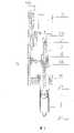
Fig. 1 is the front view of the embodiment of the invention one.
Fig. 2 is the stereogram of the embodiment of the invention one.
Fig. 3 is the logic block-diagram of the embodiment of the invention one.
Fig. 4 is the external wiring diagram of the embodiment of the invention one.
Fig. 5 is the front view of the embodiment of the invention two.
The specific embodiment
Further specify the embodiment of electric point gum machine of the present invention and working method thereof below in conjunction with accompanying drawing.
Embodiment one:
Fig. 1, Fig. 2 are respectively front view and the stereograms of the embodiment one of electric point gum machine.
Can see from above-mentioned figure: be used to store the injection barrel 1 of liquid, there is adischarging opening 1A in the central authorities of barrel bottom, and barrel 1 is fixed on the bottom that connectspedestal 6 through installing plate 1B.Be provided with pushingpiston 2 in the injection barrel 1,piston 2 can slide up and down in barrel 1, is used for pushing the liquid in the barrel 1, or sucks the liquid outside the barrel 1.Pushing piston 2 inside are equipped withbearing 2A, andpiston 2 is connected the lower end ofdrive screw 3 bybearing 2A, andscrew rod 3 can rotate with respect to piston 2.Pass through the middle and lower part that connectingplate 4A are installed inpedestal 6 withscrew rod 3 matching used hold-downnuts 4,nut 4 is with respect to invariant position, the dead in line of barrel 1.For reducing the transmission resistance, the sub-assembly ofscrew rod 3 andnut 4 can be selected ball-type for use.The top ofscrew rod 3 is provided withdrive motors 5, can select stepper motor or servomotor for use.The top 3A ofscrew rod 3 links together by the rotating shaft 5A of shaft coupling and motor 5.Be provided withrail plate 6A betweenmotor 5 and thepedestal 6.
When the rotating shaft 5A ofmotor 5 rotates, drivescrew rod 3 and innut 4, produce screw, axial displacement takes place along withscrew rod 3 longitudinal sliding motion onpedestal 6 with respect tonut 4 in motor 5.The lower end ofscrew rod 3drives piston 2 axial displacement takes place in barrel 1, acts on the liquid in the barrel.
In order to prevent the inertia injection of low viscosity fluid, the lower end of barrel discharging opening can also be provided with magnetic valve or pneumatic operated valve, is used for the injection canal of instantaneous trip discharging opening.
Fig. 3 is the logic block-diagram of present embodiment, and Fig. 4 is the external wiring diagram of present embodiment.Arithmetic control circuit 8 has an input interface, can link to each other with manipulation ofswitches 10, and by the specific control command of manual input, or reception is as the control command of the Machine-Tool Control circuit 9 of numerical control equipment.The decoder ofarithmetic control circuit 8 converts control command to electrical signal sequence.The output interface ofarithmetic control circuit 8 after electrical signal sequence amplification, shaping,exports drive circuit 7 to, promotesdrive motors 5, drivesdrive screw 3 and rotates.
Electric point gum machine of the present invention can be realized several working ways, for example:
1. continuous operation mode generally is applicable to the fluid that viscosity is lower.
Whenpulse control circuit 8 receives a triggering signal that results from Machine-Tool Control circuit 9 or manipulation ofswitches 10,instruction driving circuit 7 promotesdrive motors 5 continuously smooth ground forward rotation.Also continuously and smoothly's spiral is descending to drivescrew rod 3, promotespiston 2 and moves down, and the fluid in the extruding barrel 1 forces fluid to pass through thedischarging opening 1A of barrel 1 lower end, is expelled to surface of the work.Finish in case inject,pulse control circuit 8 can be provided with the instructions that amotor 5 oppositely rotates in short-term, drivespistons 2 trace byscrew rod 3 and moves up, and can suck the remaining fluid that discharging opening 1A outer end is not dripped as yet.
Forward rotation and the time and the speed of oppositely rotating in short-term can be adjusted respectively.
2. pulse working mode generally is applicable to the fluid that viscosity is higher.
Whenpulse control circuit 8 receives a triggering signal that results from Machine-Tool Control circuit 9 or manipulation ofswitches 10,instruction driving circuit 7 promotes the rotation that drivemotors 5 is interrupted, can be that forward rotates in short-term to add in short-term and stops, also can be that forward rotates in short-term to add oppositely and rotates in short-term.Drive pistons 2 byscrew rod 7 and produce to move down on a small quantity to add in short-term and stop, or move down on a small quantity to add on the trace and move, push fluid in the barrel 1 in the polarization mode.
Rotating in short-term can be that level and smooth formula is rotated, and also can be that pulsed is rotated, and the number of times of time of Zhuan Donging and speed, the time that stops in short-term, pulse can be adjusted respectively in short-term.
Pulse working mode helps reducing the viscosity of fluid, improves the discharging effect, improves injection speed.
3. the vibration standby mode generally is applicable to before the injection or the holding state between double injection.
Piston 1 is shaken up and down, can drive barrel 1 inner fluid and produce internal vibration, helps reducing fluid viscosity to be injected, or keeps the constant of the fluid that reduces viscosity.
Embodiment two:
Fig. 5 is the front view of the embodiment two of electric point gum machine.
As we can see from the figure, its main distinction with embodiment one is: the structure of pushingpiston 2 is different, has made plunger type into.It is different thatpiston 2 and the connection ofdrive screw 3 also have, andpiston 2 tops have external screw thread, screws in bearing block 2B bottom, andpiston 2 is connected the lower end ofscrew rod 3 by thebearing 2A in the bearing block 2B.
Electric point gum machine of the present invention can pass through manipulation ofswitches 10 to be realized,
1. fixed fire:
Press the knob down start injection,, just finish injection until loosen knob.
Press the knob down start injection, until the preset period time just finishes injection.
2. penetrate continuously:
Start injection when receiving an enabling signal until receive stop signal, just finishes injection.
3. manual:
Manually, can freely change between automatically.
4. demonstration fluid displacement:
The percentage that shows the residual fluid capacity.
5. shift to an earlier date or the injection that lags behind:
Start injection can be set in advance or be lagged behind to enabling signal; Stop signal can be set in advance or lag behind and finish injection.
The design feature of electric point gum machine of the present invention is:
1. can change thedrive screw 3 of different pitch, the requirement of realize at a high speed, high accuracy being injected.
2.drive motors 5 is installed in the top ofdrive screw 3, and it is convenient to change, and the optional scope of the model of motor is big.As select high speed, high pulling torque motor for use, be used for the fluid of injecting high viscosity.
3. the motor afterbody can be installed encoder, adopts closed-loop fashion control point adhesive dispenser, realizes the compensate function of injection stroke, is used for the workpiece injection of high-precision requirement.
4. injection barrel 1 and pushingpiston 2 are away fromnut 4 andmotor 5, and dismounting is simple, can change the barrel 1 and thepiston 2 of different-diameter easily.The barrel 1 of minor diameter andpiston 2 are fit to precise injection, and large diameter barrel 1 andpiston 2 are fit to the injection of big flow or high viscosity fluid.
Claims (10)
1. electric point gum machine comprises:
The bottom has discharging opening (1A), is used to store the injection barrel (1) of liquid;
It is characterized in that point glue equipment also comprises:
Be provided with in the described injection barrel (1), act on the pushing piston (2) of the interior liquid of barrel (1);
Be connected with described pushing piston (2) top, drive piston (2) drive screw (3) in axial sliding;
Matching used with described drive screw (3), the hold-down nut (4) of relative barrel (1) invariant position;
The top of described drive screw (3) is provided with, and can drive the drive motors (5) of screw rod (3) rotation.
2. point glue equipment according to claim 1 is characterized in that: described injection barrel (1) is installed in described hold-down nut (4) and is connected on the pedestal (6) dead in line of the axis of nut (4) and barrel (1).
3. point glue equipment according to claim 2 is characterized in that: the dead in line of the axis of described pushing piston (2) and described drive screw (3), screw rod (3) can rotate with respect to piston (2).
4. point glue equipment according to claim 3 is characterized in that: the top (3A) of described drive screw (3) is in transmission connection with the rotating shaft (5A) of drive motors (5); When the rotating shaft (5A) of drive motors (5) is rotated, drive drive screw (3) and in hold-down nut (4), produce screw, the lower end of drive screw (3) drives pushing piston (2) axial displacement takes place in injection barrel (1), acts on the liquid in the barrel (1).
5. point glue equipment according to claim 4 is characterized in that: described drive motors (5) is provided with rail plate (6A) with being connected between the pedestal (6); When the rotating shaft (5A) of drive motors (5) is rotated, drive motors (5) is along with drive screw (3) is connecting upward longitudinal sliding motion of pedestal (6), with respect to hold-down nut (4) axial displacement takes place, drive motors (5) remains unchanged with the relative distance of pushing piston (2).
6. point glue equipment according to claim 2 is characterized in that: the lower end of described discharging opening (1A) is provided with magnetic valve or pneumatic operated valve, and injection canal that can instantaneous trip discharging opening (1A) is used to prevent the inertia injection of the low fluid of viscosity.
7. the working method of electric point gum machine, it is characterized in that: the rotating shaft (5A) of control drive motors (5), continuous rotation or interruption rotation or pulse are rotated or are commutated, by drive screw (3) drive pushing piston (2), with respect to injecting the upper and lower mobile or vibration of barrel (1).
8. working method according to claim 7 is characterized in that: described interruption is rotated and can be stopped for rotating to add in short-term in short-term, also can rotate in short-term for forward rotates to add oppositely in short-term; The described rotation in short-term can be rotated for level and smooth formula, also can rotate for pulsed.
9. working method according to claim 8 is characterized in that: described continuous rotation, the angle of rotating in short-term, the described time that stops in short-term, the number of times of described pulse can be adjusted respectively.
10. working method according to claim 8, it is characterized in that: described vibration is rotating shaft (5A) rotation that commutates repeatedly, wherein the forward umber of pulse of rotating in short-term equates with the umber of pulse of oppositely rotating in short-term, by drive screw (3), drive pushing piston (2) and shake at a certain height of injection barrel (1).
Priority Applications (1)
| Application Number | Priority Date | Filing Date | Title |
|---|---|---|---|
| CNA2008100659884ACN101224454A (en) | 2008-01-28 | 2008-01-28 | Electric point gum machine and working way thereof |
Applications Claiming Priority (1)
| Application Number | Priority Date | Filing Date | Title |
|---|---|---|---|
| CNA2008100659884ACN101224454A (en) | 2008-01-28 | 2008-01-28 | Electric point gum machine and working way thereof |
Publications (1)
| Publication Number | Publication Date |
|---|---|
| CN101224454Atrue CN101224454A (en) | 2008-07-23 |
Family
ID=39856781
Family Applications (1)
| Application Number | Title | Priority Date | Filing Date |
|---|---|---|---|
| CNA2008100659884APendingCN101224454A (en) | 2008-01-28 | 2008-01-28 | Electric point gum machine and working way thereof |
Country Status (1)
| Country | Link |
|---|---|
| CN (1) | CN101224454A (en) |
Cited By (20)
| Publication number | Priority date | Publication date | Assignee | Title |
|---|---|---|---|---|
| CN102247943A (en)* | 2010-05-18 | 2011-11-23 | 鸿富锦精密工业(深圳)有限公司 | Adhesive dispensing device |
| CN102698927A (en)* | 2012-06-08 | 2012-10-03 | 中北大学 | Automatic gluing device for optical fibers |
| CN101875040B (en)* | 2010-02-09 | 2013-02-27 | 配天(安徽)电子技术有限公司 | Dispensing control method, dispensing machine and related devices |
| CN103128031A (en)* | 2011-11-24 | 2013-06-05 | 鸿富锦精密工业(深圳)有限公司 | Dispensing assembly and dispenser adopting the dispensing assembly |
| CN103831207A (en)* | 2012-11-23 | 2014-06-04 | 深圳市世椿自动化设备有限公司 | Adhesive supply apparatus with motor |
| CN103894315A (en)* | 2012-12-26 | 2014-07-02 | 科沃斯机器人科技(苏州)有限公司 | Equipment for fluid quantitative injection |
| CN104259055A (en)* | 2014-09-12 | 2015-01-07 | 大连华工创新科技股份有限公司 | Needle valve rubber valve |
| CN104511401A (en)* | 2014-12-16 | 2015-04-15 | 深圳顺络电子股份有限公司 | Glue dispensing system and glue dispensing method |
| CN107321563A (en)* | 2017-07-25 | 2017-11-07 | 佛山市四点零自动化设备有限公司 | Automatic sealing robot |
| CN108031615A (en)* | 2017-12-14 | 2018-05-15 | 天津斯巴克瑞汽车电子股份有限公司 | A kind of the automatic of gum cover smears silicone grease device and application method |
| CN108169070A (en)* | 2017-12-21 | 2018-06-15 | 广东德新科技孵化器有限公司 | A kind of plastic processing automation flowing melt device |
| CN109013216A (en)* | 2018-08-28 | 2018-12-18 | 芜湖文青机械设备设计有限公司 | A glue coating device for industrial design mold manufacturing |
| CN109382256A (en)* | 2018-10-24 | 2019-02-26 | Oppo(重庆)智能科技有限公司 | Liquid supply equipment |
| CN109569960A (en)* | 2018-11-26 | 2019-04-05 | 衡阳思迈科科技有限公司 | Conductive silver glue extrusion device |
| CN110665748A (en)* | 2019-11-07 | 2020-01-10 | 徐州鸿业仪器仪表有限公司 | Quick adhesive deposite device |
| CN111151416A (en)* | 2019-12-27 | 2020-05-15 | 中国电子产品可靠性与环境试验研究所((工业和信息化部电子第五研究所)(中国赛宝实验室)) | A pre-accelerated jet dispensing device |
| CN111907020A (en)* | 2020-07-27 | 2020-11-10 | 湖北帮友科技有限公司 | Injection molding machine micro-injection device capable of realizing high-speed and high-precision injection |
| CN112221841A (en)* | 2020-09-11 | 2021-01-15 | 安徽华铂再生资源科技有限公司 | Dispensing device for storage battery processing and working method thereof |
| CN112337751A (en)* | 2019-08-09 | 2021-02-09 | 竑腾科技股份有限公司 | Control method to prevent glue leakage from dispenser |
| CN113000309A (en)* | 2021-04-12 | 2021-06-22 | 新乡航空工业(集团)有限公司上海分公司 | Dispensing machine |
- 2008
- 2008-01-28CNCNA2008100659884Apatent/CN101224454A/enactivePending
Cited By (25)
| Publication number | Priority date | Publication date | Assignee | Title |
|---|---|---|---|---|
| CN101875040B (en)* | 2010-02-09 | 2013-02-27 | 配天(安徽)电子技术有限公司 | Dispensing control method, dispensing machine and related devices |
| CN102247943A (en)* | 2010-05-18 | 2011-11-23 | 鸿富锦精密工业(深圳)有限公司 | Adhesive dispensing device |
| US8353429B2 (en) | 2010-05-18 | 2013-01-15 | Hong Fu Jin Precision Industry (Shenzhen) Co., Ltd. | Dispensing apparatus |
| CN102247943B (en)* | 2010-05-18 | 2013-07-03 | 鸿富锦精密工业(深圳)有限公司 | Adhesive dispensing device |
| CN103128031A (en)* | 2011-11-24 | 2013-06-05 | 鸿富锦精密工业(深圳)有限公司 | Dispensing assembly and dispenser adopting the dispensing assembly |
| CN102698927A (en)* | 2012-06-08 | 2012-10-03 | 中北大学 | Automatic gluing device for optical fibers |
| CN103831207A (en)* | 2012-11-23 | 2014-06-04 | 深圳市世椿自动化设备有限公司 | Adhesive supply apparatus with motor |
| CN103894315A (en)* | 2012-12-26 | 2014-07-02 | 科沃斯机器人科技(苏州)有限公司 | Equipment for fluid quantitative injection |
| CN103894315B (en)* | 2012-12-26 | 2016-12-28 | 科沃斯机器人股份有限公司 | A kind of fluid quantitative injection device |
| CN104259055A (en)* | 2014-09-12 | 2015-01-07 | 大连华工创新科技股份有限公司 | Needle valve rubber valve |
| CN104511401A (en)* | 2014-12-16 | 2015-04-15 | 深圳顺络电子股份有限公司 | Glue dispensing system and glue dispensing method |
| CN107321563A (en)* | 2017-07-25 | 2017-11-07 | 佛山市四点零自动化设备有限公司 | Automatic sealing robot |
| CN108031615A (en)* | 2017-12-14 | 2018-05-15 | 天津斯巴克瑞汽车电子股份有限公司 | A kind of the automatic of gum cover smears silicone grease device and application method |
| CN108169070A (en)* | 2017-12-21 | 2018-06-15 | 广东德新科技孵化器有限公司 | A kind of plastic processing automation flowing melt device |
| CN109013216A (en)* | 2018-08-28 | 2018-12-18 | 芜湖文青机械设备设计有限公司 | A glue coating device for industrial design mold manufacturing |
| CN109382256A (en)* | 2018-10-24 | 2019-02-26 | Oppo(重庆)智能科技有限公司 | Liquid supply equipment |
| CN109382256B (en)* | 2018-10-24 | 2020-04-21 | Oppo(重庆)智能科技有限公司 | Liquid supply apparatus |
| CN109569960A (en)* | 2018-11-26 | 2019-04-05 | 衡阳思迈科科技有限公司 | Conductive silver glue extrusion device |
| CN112337751A (en)* | 2019-08-09 | 2021-02-09 | 竑腾科技股份有限公司 | Control method to prevent glue leakage from dispenser |
| CN110665748A (en)* | 2019-11-07 | 2020-01-10 | 徐州鸿业仪器仪表有限公司 | Quick adhesive deposite device |
| CN111151416A (en)* | 2019-12-27 | 2020-05-15 | 中国电子产品可靠性与环境试验研究所((工业和信息化部电子第五研究所)(中国赛宝实验室)) | A pre-accelerated jet dispensing device |
| CN111907020A (en)* | 2020-07-27 | 2020-11-10 | 湖北帮友科技有限公司 | Injection molding machine micro-injection device capable of realizing high-speed and high-precision injection |
| CN112221841A (en)* | 2020-09-11 | 2021-01-15 | 安徽华铂再生资源科技有限公司 | Dispensing device for storage battery processing and working method thereof |
| CN112221841B (en)* | 2020-09-11 | 2021-09-28 | 安徽华铂再生资源科技有限公司 | Dispensing device for storage battery processing and working method thereof |
| CN113000309A (en)* | 2021-04-12 | 2021-06-22 | 新乡航空工业(集团)有限公司上海分公司 | Dispensing machine |
Similar Documents
| Publication | Publication Date | Title |
|---|---|---|
| CN101224454A (en) | Electric point gum machine and working way thereof | |
| CN202621399U (en) | Electric dripping and dispensing device | |
| JP5100074B2 (en) | Pneumatic delivery system and method using linear actuation | |
| CN101407103B (en) | Injection mould servo synchronous automatic thread demoulding mechanism and control method thereof | |
| CN201342393Y (en) | High-precision glue dispensing valve | |
| CN106812761B (en) | Crank block type feedback digital hydraulic cylinder | |
| CN103123042A (en) | Variable air-capacitor device | |
| CN202752164U (en) | Novel AB adhesive dispensing device | |
| WO2012126378A1 (en) | Reciprocating servo control device for mainshaft of honing machine | |
| CN109681482B (en) | Digital hydraulic variable pump and adjusting method thereof | |
| CN208469057U (en) | A kind of wire rod automatic handling device | |
| CN206592380U (en) | Crank block type feedback digital hydraulic cylinder | |
| CN219765847U (en) | Electric dispenser | |
| CN222428439U (en) | High-precision full-automatic dispensing machine | |
| CN108799607A (en) | Friction pulley reaction type Numeric hydraulic cylinder | |
| CN201545201U (en) | Syringe-type swinging filling device | |
| CN209210350U (en) | Extrusion device for high viscosity paste | |
| CN207222260U (en) | A kind of Double-gear transmission pushes away colloid system | |
| CN201998044U (en) | Honing machine spindle reciprocating follow-up control device | |
| CN216727983U (en) | Multi-needle injection plug glue dispensing device | |
| CN202789374U (en) | Injection pump | |
| CN101436076A (en) | Automatic control system of hydraulic pump station | |
| CN220559665U (en) | Glue injection device | |
| CN218982158U (en) | Multi-component mixing glue filling mechanism | |
| CN222642423U (en) | Servo glue pushing device applied to precise glue dispensing |
Legal Events
| Date | Code | Title | Description |
|---|---|---|---|
| C06 | Publication | ||
| C57 | Notification of unclear or unknown address | ||
| DD01 | Delivery of document by public notice | Addressee:Yun Jianliang Document name:Notification of Passing Preliminary Examination of the Application for Invention | |
| PB01 | Publication | ||
| C10 | Entry into substantive examination | ||
| SE01 | Entry into force of request for substantive examination | ||
| C57 | Notification of unclear or unknown address | ||
| DD01 | Delivery of document by public notice | Addressee:Yun Jianliang Document name:Notice of application for publication of patent for invention and entry into the substantive examination procedure | |
| C57 | Notification of unclear or unknown address | ||
| DD01 | Delivery of document by public notice | Addressee:Yun Jianliang Document name:Notification of Passing Examination on Formalities | |
| C57 | Notification of unclear or unknown address | ||
| DD01 | Delivery of document by public notice | Addressee:Yun Jianliang Document name:the First Notification of an Office Action | |
| C02 | Deemed withdrawal of patent application after publication (patent law 2001) | ||
| WD01 | Invention patent application deemed withdrawn after publication | Open date:20080723 |