CN101223619A - breaker - Google Patents
breakerDownload PDFInfo
- Publication number
- CN101223619A CN101223619ACNA2005800510291ACN200580051029ACN101223619ACN 101223619 ACN101223619 ACN 101223619ACN A2005800510291 ACNA2005800510291 ACN A2005800510291ACN 200580051029 ACN200580051029 ACN 200580051029ACN 101223619 ACN101223619 ACN 101223619A
- Authority
- CN
- China
- Prior art keywords
- mentioned
- circuit breaker
- shaft
- axle
- connecting portion
- Prior art date
- Legal status (The legal status is an assumption and is not a legal conclusion. Google has not performed a legal analysis and makes no representation as to the accuracy of the status listed.)
- Granted
Links
Images


Classifications
- H—ELECTRICITY
- H01—ELECTRIC ELEMENTS
- H01H—ELECTRIC SWITCHES; RELAYS; SELECTORS; EMERGENCY PROTECTIVE DEVICES
- H01H71/00—Details of the protective switches or relays covered by groups H01H73/00 - H01H83/00
- H01H71/10—Operating or release mechanisms
- H01H71/66—Power reset mechanisms
- H01H71/68—Power reset mechanisms actuated by electromagnet
- H—ELECTRICITY
- H01—ELECTRIC ELEMENTS
- H01H—ELECTRIC SWITCHES; RELAYS; SELECTORS; EMERGENCY PROTECTIVE DEVICES
- H01H3/00—Mechanisms for operating contacts
- H01H3/32—Driving mechanisms, i.e. for transmitting driving force to the contacts
- H01H3/48—Driving mechanisms, i.e. for transmitting driving force to the contacts using lost-motion device
- H—ELECTRICITY
- H01—ELECTRIC ELEMENTS
- H01H—ELECTRIC SWITCHES; RELAYS; SELECTORS; EMERGENCY PROTECTIVE DEVICES
- H01H3/00—Mechanisms for operating contacts
- H01H3/32—Driving mechanisms, i.e. for transmitting driving force to the contacts
- H01H3/42—Driving mechanisms, i.e. for transmitting driving force to the contacts using cam or eccentric
- H—ELECTRICITY
- H01—ELECTRIC ELEMENTS
- H01H—ELECTRIC SWITCHES; RELAYS; SELECTORS; EMERGENCY PROTECTIVE DEVICES
- H01H71/00—Details of the protective switches or relays covered by groups H01H73/00 - H01H83/00
- H01H71/10—Operating or release mechanisms
- H01H71/50—Manual reset mechanisms which may be also used for manual release
- H01H71/52—Manual reset mechanisms which may be also used for manual release actuated by lever
- H01H71/528—Manual reset mechanisms which may be also used for manual release actuated by lever comprising a toggle or collapsible link between handle and contact arm, e.g. sear pin mechanism
Landscapes
- Physics & Mathematics (AREA)
- Electromagnetism (AREA)
- Driving Mechanisms And Operating Circuits Of Arc-Extinguishing High-Tension Switches (AREA)
Abstract
Description
Translated fromChinese技术领域technical field
本发明涉及具有固定接点和可动接点的断路器,该断路器还备有使该可动接点与固定接点闭合或断开的电磁操作机构。The present invention relates to a circuit breaker having a fixed contact and a movable contact, and the circuit breaker is further provided with an electromagnetic operating mechanism for closing or opening the movable contact and the fixed contact.
背景技术Background technique
已往的低电压断路器,以弹簧操作式的断路器为主流,该弹簧操作式的断路器,利用被蓄势的弹簧释放时放出的能量进行可动接点的闭合或断开操作(例如参见专利文献1)。The traditional low-voltage circuit breakers are mainly spring-operated circuit breakers. The spring-operated circuit breakers use the energy released by the stored spring to close or open the movable contacts (for example, see patent Literature 1).
另外,还开发出用电磁操作机构进行真空开关的可动接点的闭合或断开的断路器(例如参见专利文献2)。In addition, a circuit breaker in which a movable contact of a vacuum switch is closed or opened by an electromagnetic operating mechanism has also been developed (for example, see Patent Document 2).
专利文献1:日本特开平6-89650号公报(图1~5、第2页)Patent Document 1: Japanese Patent Application Laid-Open No. 6-89650 (Figs. 1-5, page 2)
专利文献2:EP1214727B1号公报(图1~图2、第2~5页)Patent Document 2: Publication No. EP1214727B1 (Figs. 1-2, pages 2-5)
发明内容Contents of the invention
专利文献1揭示的低压断路器,其操作机构采用多个弹簧销和连杆,机器尺寸大,零部件数目多,为了确保机器的可靠性,必须定期地进行维护。The low-voltage circuit breaker disclosed in
另外,专利文献2揭示的断路器,在进行可动接点与固定接点的闭合或断开操作的操作轴、与电磁操作机构的驱动轴之间设置的连杆的长度也比较长,同样地,在提高机器可靠性及小型化方面,有待于改进。另外,专利文献2揭示的断路器,备有用于实现接点部的短时间通电性能的U字形电路,必须要根据电流容量,分别变更U字形电路的形状和尺寸。这里所说的短时间通电性能,是将上述断路器作为主断路器使用时所必需的性能之一,是指在短路事故等大电流通电时、在保护继电器装置动作以进行安全的断路动作为止的期间,使短路电流持续通电的性能。通常,在大电流通电时,接点间产生大的电磁斥力,可动接点可能会上浮,所以,要求专利文献2揭示的U字形电路那样的使可动接点不产生上浮的构造。In addition, in the circuit breaker disclosed in Patent Document 2, the length of the link provided between the operating shaft for closing or opening the movable contact and the fixed contact and the drive shaft of the electromagnetic operating mechanism is also relatively long. In terms of improving the reliability and miniaturization of the machine, it needs to be improved. In addition, the circuit breaker disclosed in Patent Document 2 has a U-shaped circuit for realizing short-time energization performance of the contact portion, and it is necessary to change the shape and size of the U-shaped circuit according to the current capacity. The short-time energization performance mentioned here is one of the performances necessary when the above-mentioned circuit breaker is used as a main circuit breaker. It refers to the operation of the protective relay device to perform a safe circuit breaking operation when a large current is energized such as a short-circuit accident. During the period, the performance of making the short-circuit current continuously energized. Usually, when a large current is energized, a large electromagnetic repulsion is generated between the contacts, and the movable contact may float up. Therefore, a structure that prevents the movable contact from floating like the U-shaped circuit disclosed in Patent Document 2 is required.
本发明是为了解决已往的断路器中所存在的问题而作出的,其目的是提供在得到操作机构简单化、小型化的同时实现控制性及可靠性的提高的断路器。The present invention is made to solve the problems of conventional circuit breakers, and an object of the present invention is to provide a circuit breaker with improved controllability and reliability while achieving simplification and miniaturization of an operating mechanism.
本发明的断路器,备有固定导体、可动子、轴、操作臂、和电磁操作机构;上述固定导体具有固定接点;上述可动子具有可动接点,该可动子被驱动以相对于上述固定接点闭合或断开;上述轴能以轴心为中心转动;上述操作臂相对于上述轴心在垂直方向隔开第1预定距离地借助第1连接部可转动地与上述轴连接,并且借助第2连接部与上述可动子连接;上述电磁操作机构具有驱动轴,该驱动轴借助相对于上述第1连接部设在上述轴的周向不同位置的第3连接部,与上述轴连接,并且,在相对于上述轴心隔开第2预定距离并正交的直线上被驱动移动;通过激励该电磁操作机构、驱动上述驱动轴,使上述轴旋转,经由上述操作臂驱动上述可动子。The circuit breaker of the present invention is provided with a fixed conductor, a movable element, a shaft, an operating arm, and an electromagnetic operating mechanism; the fixed conductor has a fixed contact; the movable element has a movable contact, and the movable element is driven to The above-mentioned fixed contact is closed or opened; the above-mentioned shaft can rotate around the axis; the above-mentioned operating arm is rotatably connected to the above-mentioned shaft by a first connecting part with a first predetermined distance in the vertical direction relative to the above-mentioned axis, and It is connected to the above-mentioned mover through the second connection part; the above-mentioned electromagnetic operation mechanism has a drive shaft, and the drive shaft is connected to the above-mentioned shaft through the third connection part provided at a different position in the circumferential direction of the shaft relative to the above-mentioned first connection part. , and is driven to move on a straight line that is separated by a second predetermined distance and perpendicular to the above-mentioned shaft center; by exciting the electromagnetic operating mechanism and driving the above-mentioned drive shaft, the above-mentioned shaft is rotated, and the above-mentioned movable arm is driven through the above-mentioned operation arm. son.
本发明中,将轴和操作臂连接的第1连接部,包含了将上述轴和上述操作臂直接连接的连接部的情形、和通过其它部件将上述轴和上述操作臂间接地连接的连接部的情形这两种情形。In the present invention, the first connection part connecting the shaft and the operation arm includes the connection part directly connecting the shaft and the operation arm, and the connection part indirectly connecting the shaft and the operation arm through other members. The situation of these two situations.
另外,在本发明中,将操作臂和可动子连接的第2连接部,包含了将上述操作臂和上述可动子直接连接的连接部的情形、和通过其它部件将上述操作臂和上述可动子间接地连接的连接部的情形这两种情形。In addition, in the present invention, the second connecting portion connecting the operating arm and the movable member includes the case where the connecting portion directly connects the operating arm and the movable member, and the connection between the operating arm and the movable member through other components. There are two cases in the case of the connection part where the mover is indirectly connected.
另外,在本发明中,将轴和驱动轴连接的第3连接部,包含了将上述轴和上述驱动轴直接连接的连接部的情形、和通过其它部件将上述轴和上述驱动轴间接地连接的连接部的情形这两种情形。In addition, in the present invention, the third connecting portion connecting the shaft and the driving shaft includes the case of directly connecting the shaft and the driving shaft, and indirectly connecting the shaft and the driving shaft through other members. The situation of the connecting part of these two situations.
根据本发明的断路器,备有操作臂和电磁操作机构。上述操作臂相对于轴心在垂直方向隔开第1预定距离地借助第1连接部可转动地与轴连接,并且借助第2连接部与可动子连接。上述电磁操作机构具有驱动轴,该驱动轴借助相对于上述第1连接部设在上述轴的周向不同位置的第3连接部与上述轴连接,并且,在相对于上述轴心隔开第2预定距离并正交的直线上被驱动移动。通过激励该电磁操作机构、驱动上述驱动轴,使上述轴旋转,经由上述操作臂驱动上述可动子。因此,操作机构部可以简单且小型化,并且可提高断路器的控制性和可靠性。According to the circuit breaker of the present invention, an operating arm and an electromagnetic operating mechanism are provided. The operation arm is rotatably connected to the shaft via a first connection portion with a first predetermined distance in a vertical direction relative to the shaft center, and is connected to the movable member via a second connection portion. The above-mentioned electromagnetic operation mechanism has a drive shaft connected to the above-mentioned shaft through a third connection part provided at a different position in the circumferential direction of the shaft relative to the above-mentioned first connection part, and is spaced apart from the center of the shaft by a second It is driven to move on a predetermined distance and perpendicular to the straight line. By energizing the electromagnetic operation mechanism and driving the drive shaft, the shaft is rotated, and the movable element is driven via the operation arm. Therefore, the operating mechanism unit can be simplified and downsized, and the controllability and reliability of the circuit breaker can be improved.
附图说明Description of drawings
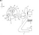
图1是表示本发明实施方式1的断路器的构造图。FIG. 1 is a structural diagram showing a circuit breaker according to
图2是用于说明本发明实施方式1的断路器动作的主要部构造图。Fig. 2 is a structural diagram of main parts for explaining the operation of the circuit breaker according to
图3是用于说明本发明实施方式1的断路器动作的主要部构造图。Fig. 3 is a structural diagram of main parts for explaining the operation of the circuit breaker according to
图4是用于说明本发明实施方式1的断路器动作的曲线图。Fig. 4 is a graph for explaining the operation of the circuit breaker according to
图5是本发明实施方式2的断路器主要部的构造图。Fig. 5 is a structural diagram of main parts of a circuit breaker according to Embodiment 2 of the present invention.
图6是本发明实施方式3的断路器主要部的构造图。Fig. 6 is a structural diagram of main parts of a circuit breaker according to
图7是本发明实施方式4的断路器主要部的构造图。Fig. 7 is a structural diagram of main parts of a circuit breaker according to
图8是本发明实施方式5的断路器主要部的构造图。Fig. 8 is a structural diagram of main parts of a circuit breaker according to Embodiment 5 of the present invention.
图9是用于说明本发明实施方式5的断路器动作的主要部构造图。Fig. 9 is a structural diagram of main parts for explaining the operation of the circuit breaker according to Embodiment 5 of the present invention.
图10是本发明实施方式6的断路器主要部的构造图。Fig. 10 is a structural diagram of main parts of a circuit breaker according to Embodiment 6 of the present invention.
图11是本发明实施方式7的断路器主要部的构造图。Fig. 11 is a structural diagram of main parts of a circuit breaker according to
图12是本发明实施方式8的断路器主要部的构造图。Fig. 12 is a structural diagram of main parts of a circuit breaker according to
图13是本发明实施方式9的断路器主要部的构造图。Fig. 13 is a structural diagram of main parts of a circuit breaker according to
具体实施方式Detailed ways
实施方式1
图1是表示本发明实施方式1的断路器的构造图。图2和图3是用于说明实施方式1的断路器动作的说明图。FIG. 1 is a structural diagram showing a circuit breaker according to
图1中,绝缘框体1具有内部被绝缘壁103分隔的空间部101、102,还备有从外部贯通到空间部101的一对固定导体21、22。固定导体21、22分别与图未示的电源侧导体及负荷侧导体连接着。固定导体21及固定导体22也分别被称为电源侧端子和负荷侧端子。在露出到绝缘框体1的空间部101内的固定导体21的端部,固定着固定接点211。In FIG. 1 , an
可动子3由联接销4可转动地支承着,在与固定接点211相向的位置固定着可动接点311。压接弹簧5把可动子3朝着以联接销4为中心顺时针转动的方向推压,以在可动接点311与固定接点211闭合时对两接点间施加接触压力。可动子3和固定导体22,借助可挠曲的可挠导体6电连接。The
设在绝缘框体1的空间部102内的板状连接板8,固定在能绕轴心91转动地支撑的轴9上。连接板8备有从其外周部朝着内侧倾斜的长槽状连接孔81。操作臂7贯穿设在绝缘框体1的分隔壁103上的贯通孔104,其一端可转动地与可动子3连接,另一端通过连接销71可转动地与连接板8连接着。由连接销71形成的、连接板8与操作臂7另一端的连接部构成第1连接部。该第1连接部设在距离轴9的轴心91为第1预定距离即半径r的位置。图1中,由于轴心91和连接销71在y轴上重合,所以,第1连接部相对于轴心91的y轴方向的距离ra与半径r相等,但是,众所周知,该y轴方向的距离ra依据连接板8及轴9的旋转角而减小。操作臂7的一端与可动子3的连接部构成第2连接部。The plate-shaped connecting
作为电磁操作手段的电磁操作机构10设在绝缘框体1的空间部102内。该电磁操作机构10备有由磁性体形成的磁轭11、固定在该磁轭11内侧的第1线圈12及第2线圈13、固定在第1线圈12与第2线圈13之间的永磁铁14、能在第1线圈12及第2线圈13和永磁铁14的内侧沿图1中y轴方向移动的可动铁心15、和固定在该可动铁心15上并随着可动铁心15的移动在y轴方向的直线上往复移动的驱动轴16。An
由于需要保持可动接点311的闭合和断开状态,故电磁操作机构10构成为双稳定型构造。图1中,可动铁心15被永磁铁15的磁力吸附在磁轭11的图1上方部并保持稳定,但是,在激励线圈13时,在线圈13产生的磁通作用下,将可动铁心15驱动到图1的下方、使之与磁轭11的下方部相接。这时虽然线圈13已被消去激励,但是可动铁心15在永磁铁14的磁力的作用下被稳定在吸附于磁轭11的下方的状态。接着,若在该状态时激励线圈12,则可动铁心15被线圈12的磁力驱动到图1的上方,如图1所示,被吸附在磁轭11的上方部。这时,虽然线圈13已被消去激励,但是可动铁心15在永磁铁14的磁力的作用下被稳定在吸附于磁轭11的下方的状态。Since the closed and open states of the
驱动轴16通过连接销161与连接板8连接着,该连接销161嵌合在连接板8的连接孔81内。由连接销161及连接孔81形成的连接部构成第3连接部。驱动轴16在相对于轴心91隔开距离rb并正交的y轴方向的直线上移动。该距离rb相当于第2预定距离。虽然连接板8与轴9一起绕轴心91旋转,但是由于连接孔81形成为从连接板8的外周部朝着内侧倾斜的形状,所以,即使连接板8旋转,连接销161也以与轴心91之间的x轴方向的距离rb总保持为一定的状态与连接孔81嵌合。The
图1表示可动接点311从固定接点211上断开的状态。在该状态,若激励电磁操作机构10的线圈13,则可动铁心1 5被朝图1下方驱动,固定在可动铁心15上的驱动轴16沿y轴朝下方移动。通过驱动轴16沿y轴朝下方移动,与驱动轴16连接着的连接板8通过由连接销161及连接孔81构成的第3连接部被驱动而朝逆时针方向转动。连接板8朝逆时针方向转动时,通过连接销71与连接板8连接着的操作臂7沿着x轴被朝右方向驱动、将可动子3朝图1中右方向驱动。FIG. 1 shows a state where the
图2表示可动子3被朝图1中右方向驱动从而可动接点311开始接触固定接点211的闭合初期状态。该闭合动作时,借助压接弹簧5的作用,在固定接点211与可动接点311之间施加了接触压力,在操作臂7上产生了箭头方向的负荷力Fa。另一方面,在电磁操作机构10的驱动轴16上,基于作用在可动铁心15上的吸引力的操作力Fb产生在箭头方向。因此,作用在固定着连接板8的轴9上的旋转力矩是,使轴9顺时针方向旋转的负荷力矩Ma(=Fa·ra)、和使轴9逆时针方向旋转的操作力矩Mb(=Fb·rb)。FIG. 2 shows the initial closing state in which the
这里,Ma=Fa·ra,Mb=Fb·rb。要使轴9及连接板8逆时针方向旋转,必须满足Mb>Ma的关系。Here, Ma=Fa·ra, Mb=Fb·rb. To make the
克服了负荷力矩Ma的操作力矩Mb作用到连接板8上时,连接板8从图2的位置进一步朝逆时针方向转动,到达图3所示的可动接点311的闭合完成位置。在该闭合完成状态,轴9的轴心91、连接销71的中心和联接销4的中心位于一直线上,驱动轴16、连接板8、轴9、操作臂7及可动子3停止在该位置,保持着可动接点311对固定接点211的闭合。When the operating moment Mb that overcomes the load moment Ma acts on the
如前所述,轴心91与连接销71的y轴方向的距离ra,在图1所示位置最大,并依据连接板8的旋转角而减小。另一方面,连接销161与轴心91之间的x轴方向的距离rb总保持为一定。因此,如果使压接弹簧5的负荷力Fa为一定,则以图1的位置为基点,负荷力矩Ma随着连接板8的旋转角而减小。另一方面,由于即使连接板8旋转,距离rb也保持一定,所以,操作力矩Mb只随着电磁操作机构10的驱动力Fb而变化。As mentioned above, the distance ra between the
图4表示压接弹簧5作用在连接板8上的负荷力Fa与负荷力矩Ma的关系。图4中,横轴表示操作臂7的行程(mm),纵轴表示力(N)。在操作臂7的行程t1处,压接弹簧5产生的负荷力Fa上升,以后,操作臂7从图1所示位置经过图2所示位置、在到达图3所示可动接点311的闭合完成位置之前,与行程增大相应地,如图4中实线所示,负荷力Fa直线地增大。另一方面,与操作臂7从图1位置朝图3位置的移动对应地,连接板8和轴9旋转,所以,如上所述,轴心91与连接销71之间的y轴方向的距离ra随着连接板8和轴9的旋转角而减小。结果,作用在连接板8和轴9上的负荷力矩Ma如图4中虚线所示地变化,在图3的可动接点311的闭合完成位置,该负荷力矩Ma成为大致最小。该闭合完成位置中的操作臂7的行程是图4中的t2。FIG. 4 shows the relationship between the load force Fa and the load moment Ma acting on the
将可动接点311与固定接点211闭合,并且为了保持图3所示的闭合完成状态,必须持续地对连接板8施加负荷力矩Ma以上的操作力矩Mb。但是,如前所述,由于负荷力矩Ma随着连接板8的旋转角而减小、在闭合完成状态成为最小,所以,保持闭合完成状态的操作力矩Mb只要大于等于该最小时的负荷力矩Ma即可。这样,就可以用比较小型的电磁操作机构10的永磁铁14对可动铁心15的吸附力来保持闭合完成状态。In order to close the
下面,说明从图3所示的闭合完成状态断开可动接点311时的动作。在图3的闭合完成状态,电磁操作机构10的可动铁心15被吸附在与图1所示位置相反的位置、即磁轭11的图1下侧并保持稳定。这时,如果激励线圈12,则线圈12产生的磁通作用把可动铁心15吸引到图1的上方,在操作臂16上产生了与图2所示方向相反的操作力Fb。借助基于该操作力Fb的操作力矩Mb(=Fb·rb),连接板8绕着轴9的轴心91开始朝顺时针方向转动。Next, the operation when the
在图3所示的闭合完成状态,虽然轴心91、连接销71和联接销4排列在一直线上并静止,但是,连接板8的顺时针方向的转动破坏了该排列,操作臂7从图4的行程t2朝着行程t1的方向移行。这时,与顺时针方向旋转的连接板8的旋转角相应地,轴心91与连接销71之间的y轴方向的距离ra增大,所以,如图4所示,负荷力矩Ma急剧增大。结果,连接板8受到大的负荷力矩Ma、急剧地朝顺时针方向旋转,操作臂7使可动子3的可动接点311脱离固定接点211,成为图1所示的断开状态并稳定住。In the closing completion state shown in Figure 3, although the
在图3所示的闭合完成状态下把连接在固定导体21、22之间的外部电路(图未示)闭合通电时,例如,若发生了短路事故等,则虽然在固定接点211与可动接点311之间因大电流而产生了大的电磁斥力,但是,如图3所示,在闭合完成状态,由于轴9的轴心91、连接销71的中心和联接销4的中心位于一直线上,所以,由电磁斥力产生的使旋转板8要朝顺时针方向转动的负荷力矩被削弱,连接板8不转动,可动接点311不脱离固定接点211。因此,即使将该断路器作为主断路器使用,也能实现短时间通电性能。When the external circuit (not shown) connected between the fixed
这样,根据本发明实施方式1的断路器,不必像已往的装置那样、为了减轻电磁操作机构所需的驱动力而采用多个连杆并利用该连杆比减轻负荷力,能使操作机构部简单且小型化。并且,可以提高断路器的控制性、可靠性以及维护性。In this way, according to the circuit breaker according to
实施方式2Embodiment 2
图5是本发明实施方式2的断路器主要部的构造图。图5中,连接连杆17分别通过连接销171、172可转动地与电磁操作机构10的驱动轴16和连接板8连接。借助于连接销17的驱动轴16与连接板8的连接构成第3连接部,相当于实施方式1中的连接板8的连接孔81与连接销161形成的第3连接部。该第3连接部在保持驱动轴16在图5中上下方向(y轴方向)的直线上的移动的状态下连接驱动轴16与连接板8。Fig. 5 is a structural diagram of main parts of a circuit breaker according to Embodiment 2 of the present invention. In FIG. 5 , the connecting
其它构造与实施方式1的断路器相同。Other structures are the same as those of the circuit breaker in
根据该实施方式2的断路器,不必设置连接孔,制造容易。According to the circuit breaker of Embodiment 2, it is not necessary to provide connection holes, and it is easy to manufacture.
实施方式3
图6是本发明实施方式3的断路器主要部的构造图。图6中,在连接板8上固定着挡销801。当连接板8转动到了闭合完成位置(图6所示位置)时,销承接件802与挡销801卡合、使连接板8停止,使轴9的轴心91、连接销71和联接销4位于一直线上、并保持该状态。Fig. 6 is a structural diagram of main parts of a circuit breaker according to
其它的构造与实施方式1相同。Other configurations are the same as those in
根据该实施方式3的断路器,能防止因长期使用造成的接点磨耗、组装的偏差等引起的、在闭合完成状态的位置错动,可得到稳定的动作性能。According to the circuit breaker according to
实施方式4
图7是本发明实施方式4的断路器主要部的构造图。图7中,连动轴1601的一端通过连接销1611可转动地与电磁操作机构10的驱动轴16连接着。挡杆1602的一端可转动地由支持销1613支持着,其大致中央部通过连接销1612可转动地与连动轴1601的另一端连接着。在该止挡连杆1602的另一端固定着挡销8011。如图7所示,在断路器的闭合动作完成后,挡销8011如打入楔子那样地与连接板8的缺口部(图未示)卡合,保持闭合完成时的连接板8及轴9的位置,阻止连接板8朝顺时针及逆时针方向转动。Fig. 7 is a structural diagram of main parts of a circuit breaker according to
使断路器断开动作时,对电磁操作机构10发出断开指令,将驱动轴16朝图7上方驱动。这样,通过连动轴1601与驱动轴16连接着的挡杆1602,以支持销1613为中心朝逆时针方向转动,挡销8011与连接板8缺口部的卡合被解除,连接板8朝顺时针方向转动,进行可动接点311的断开动作。When the circuit breaker is turned off, an off command is issued to the
实施方式3中,挡销801的主要目的是防止连接板8和轴9越过闭合完成位置进一步朝逆时针方向旋转。而本实施方式4中,挡销8011的目的是,防止闭合完成时的连接板8朝顺时针及逆时针方向的任一方向转动,完全地保持闭合完成时的连接板8的旋转角度。In
实施方式4中,如图7所示,闭合完成后的轴9、连接销71和联接销4的各自轴心不排列在一直线上,而是以轴9的轴心91为中心,连接销71比联接销4位于顺时针方向的前方。因此,虽然因短路等的大电流流过接点间时产生的大电磁斥力而对连接板8作用顺时针方向的大旋转力,但是,利用与连接板8的缺口部卡合着的挡销8011来阻止连接板8及轴9的旋转,所以,能实现短时间通电性能。其它的构造与实施方式1相同。In
另外,图7中,采用连动轴1601和挡杆1602而使驱动轴16和挡销8011机械地连动,但是,也可以采用使电磁操作机构10的动作与挡销8011的动作电连动等的其它的方式使它们连动。In addition, in Fig. 7, the
实施方式5Embodiment 5
图8和图9是本发明实施方式5的断路器主要部的构造图。图8表示断开完成状态,图9表示闭合完成状态。如图8和图9所示,设在连接板8上的连接孔810由弯曲成L字形相连的第1孔部811和第2孔部812构成。在图8所示的断开完成状态,设在驱动轴16上的连接销161与连接孔810的第2孔部嵌合。在图9所示的闭合完成状态,连接销161与连接孔810的第1孔部811嵌合。8 and 9 are structural diagrams of main parts of a circuit breaker according to Embodiment 5 of the present invention. FIG. 8 shows the opening completion state, and FIG. 9 shows the closing completion state. As shown in FIGS. 8 and 9 , the
其它构造与实施方式1相同。Other configurations are the same as those in
在可动接点311的闭合完成状态,因作用在操作臂7上的负荷力Fa,如图9所示,负荷分力Fb2通过连接板8朝箭头方向作用在连接销161上。如果与连接销161卡合的连接孔810的第1孔部811的接触面平行于驱动轴16的移动方向,则负荷分力Fb2只是图9的水平方向分量,在图9的上下方向、即电磁操作机构10的驱动轴16的移动方向,负荷分力除了因制作偏差而产生的微小成分外,几乎不存在。因此,对于电磁操作机构10来说,保持闭合完成状态并不需要大的保持力,电磁操作机构10不必大型化,就可以保持闭合完成状态。In the closed state of the
实施方式6Embodiment 6
图10是本发明实施方式6的断路器主要部的构造图。该实施方式6中,如图10所示,连接孔820备有约以120度的角度弯曲相连的第1孔部821和第2孔部822。在可动接点的闭合完成状态,设在驱动轴(图未示)上的连接销161与连接孔820的第2孔部822的倾斜壁部卡合。Fig. 10 is a structural diagram of main parts of a circuit breaker according to Embodiment 6 of the present invention. In Embodiment 6, as shown in FIG. 10 , the
图10表示闭合完成状态中的、连接销161与连接孔820的卡合状态。借助与作用在操作臂上的图9所示负荷力Fa同样的负荷力Fa(图未示),在连接销161上作用着箭头方向的负荷分力Fb3。如果如图10所示地定义X轴、Y轴的方向,则在箭头方向产生了与驱动轴的移动方向相同方向的负荷分力Fb3y,其作用在电磁操作机构的驱动轴上。另一方面,连接销161与第2孔部822的壁部卡合而产生的摩擦力Fc,沿着第2孔部822的壁部作用,其y轴方向的分力作为摩擦分力Fcy作用在驱动轴的移动方向。FIG. 10 shows the engagement state of the
这里,Fcy=μ·Fb3,式中,μ是摩擦系数。Here, Fcy=μ·Fb3, where μ is the coefficient of friction.
该摩擦分力Fcy与负荷分力Fb3y方向相反,把通过连接销161使驱动轴朝断开方向移动的负荷分力Fb3y削减。摩擦力Fc与连接孔820的第2孔部822侧面的摩擦系数μ成正比,所以,如果在连接孔820的至少第2孔部822的壁部配置具有大摩擦系数的高摩擦部件,使摩擦力Fc积极地作用在连接销161上,就可产生保持断路器的闭合完成状态的大摩擦分力Fcy,可提高大电流通电时的耐电磁斥力特性。This friction component force Fcy is opposite to the direction of the load component force Fb3y, and reduces the load component force Fb3y that moves the drive shaft in the opening direction via the
其它的构造与实施方式1相同。Other configurations are the same as those in
实施方式7
图11是本发明实施方式7的断路器主要部的构造图。Fig. 11 is a structural diagram of main parts of a circuit breaker according to
在断路器的闭合完成状态、上述负荷力Fa作用在连接销161上时,与驱动轴16的移动方向平行方向(y轴方向)的负荷分力和与之垂直方向(x轴方向)的负荷分力作用在驱动轴16上,由于垂直方向(x轴方向)的负荷分力的影响,驱动轴16有变形的可能。When the circuit breaker is closed and the above-mentioned load force Fa acts on the
为此,在图11所示的实施方式7中,将电磁操作机构10的驱动轴16加长,在连接板8的两侧用一对轴承171、172支承该驱动轴16。在这些轴承171、172之间,连接销161设在驱动轴16上并嵌合在连接板8的连接孔810内。Therefore, in
根据该实施方式7,由于用一对轴承171、172支承着驱动轴16,所以,可防止驱动轴7的变形,可提高大电流通电时的耐电磁力特性。According to the seventh embodiment, since the
实施方式8
低电压断路器通常多用于3相电路中,备有与3相的各相对应的固定接点及可动接点的3相用断路器已经普及。在该3相用断路器中,电磁操作机构的操作方式可以是3相一并地进行闭合或断开的操作,或者也可以各相分别地进行闭合和断开的操作。Low-voltage circuit breakers are generally used in 3-phase circuits, and 3-phase circuit breakers equipped with fixed contacts and movable contacts corresponding to each of the 3 phases have become popular. In this three-phase circuit breaker, the electromagnetic operating mechanism may be operated to close or open the three phases collectively, or to perform closing and opening operations for each phase separately.
图12表示本发明实施方式8的3相用断路器主要部的构造,用一个电磁操作机构10一并地操作各相。图12中,轴9固定着相同构造的3个连接板8a、8b、8c。这些连接板8a、8b、8c分别与可动接点311a、311b、311c连接着。各连接板8a、8b、8c与可动接点311a、311b、311c的连接构造,与实施方式1~7中的任一个相同。可动接点311a、311b、311c相对于固定接点211 a、211b、211c闭合或断开,这些固定接点211a、211b、211c分别与3相的各相导体连接。FIG. 12 shows the structure of main parts of a three-phase circuit breaker according to
电磁操作机构10的驱动轴16与一个连接板8b连接着,驱动该连接板8b、使轴9旋转,3相一并地进行闭合或断开的操作。连接板8b与驱动轴16的连接构造与实施方式1~7中的任一个相同。The
根据该实施方式8,可以得到具有与实施方式1~7中任一个断路器同样效果的3相用断路器。According to this eighth embodiment, a circuit breaker for three phases having the same effect as any one of the circuit breakers in
实施方式9
图13表示本发明实施方式9的断路器主要部的构造,另外地设有与电磁操作机构10的驱动轴16连接的连接板8d。其它的构造与实施方式8相同。FIG. 13 shows the structure of the main part of the circuit breaker according to
根据该实施方式9,与可动接点311a、311b、311c连接的连接板8a、8b、8c、和与驱动轴16连接的连接板8d,以不同的角度固定在轴9上,可形成最合适各连接的构造。According to
在上述各实施方式1~9中,采用通常的可动接点和固定接点,但是,也可以用真空阀构成这些接点。In each of the first to ninth embodiments described above, ordinary movable contacts and fixed contacts are used, but these contacts may also be constituted by vacuum valves.
本发明的断路器可作为通断低电压配电线等的断路器使用。The circuit breaker of the present invention can be used as a circuit breaker for switching low-voltage distribution lines and the like.
Claims (9)
Applications Claiming Priority (1)
| Application Number | Priority Date | Filing Date | Title |
|---|---|---|---|
| PCT/JP2005/013396WO2007010608A1 (en) | 2005-07-21 | 2005-07-21 | Breaker |
Publications (2)
| Publication Number | Publication Date |
|---|---|
| CN101223619Atrue CN101223619A (en) | 2008-07-16 |
| CN101223619B CN101223619B (en) | 2012-05-30 |
Family
ID=37668497
Family Applications (1)
| Application Number | Title | Priority Date | Filing Date |
|---|---|---|---|
| CN2005800510291AExpired - Fee RelatedCN101223619B (en) | 2005-07-21 | 2005-07-21 | breaker |
Country Status (4)
| Country | Link |
|---|---|
| KR (1) | KR100967249B1 (en) |
| CN (1) | CN101223619B (en) |
| DE (1) | DE112005003632B4 (en) |
| WO (1) | WO2007010608A1 (en) |
Cited By (2)
| Publication number | Priority date | Publication date | Assignee | Title |
|---|---|---|---|---|
| CN103971997A (en)* | 2013-02-01 | 2014-08-06 | 通用电气公司 | Electrical Operator For Circuit Breaker And Method Thereof |
| CN111052288A (en)* | 2017-08-21 | 2020-04-21 | 三菱电机株式会社 | Circuit breaker |
Families Citing this family (2)
| Publication number | Priority date | Publication date | Assignee | Title |
|---|---|---|---|---|
| JP5490147B2 (en)* | 2010-01-13 | 2014-05-14 | 三菱電機株式会社 | Electromagnetic operation switchgear |
| KR101759601B1 (en) | 2015-12-28 | 2017-07-31 | 엘에스산전 주식회사 | Delay time generation apparatus for air circuit breaker |
Family Cites Families (9)
| Publication number | Priority date | Publication date | Assignee | Title |
|---|---|---|---|---|
| DE650810C (en)* | 1933-02-12 | 1937-10-02 | Siemens Schuckertwerke Akt Ges | Electromagnetic drive for executing two movements in opposite directions, especially for switching electrical switches on and off |
| JPS53141473A (en)* | 1977-05-17 | 1978-12-09 | Terasaki Denki Sangyo Kk | Air circuit breaker |
| JPS55121233A (en)* | 1979-03-14 | 1980-09-18 | Terasaki Denki Sangyo Kk | Atmosphere breaker |
| JPS59182823U (en)* | 1983-05-24 | 1984-12-05 | 日新電機株式会社 | Circuit breaker tripping device |
| IT1313278B1 (en)* | 1999-07-30 | 2002-07-17 | Abb Ricerca Spa | LOW VOLTAGE POWER SWITCH. |
| DE10049728C2 (en)* | 2000-09-28 | 2003-01-02 | Siemens Ag | Drive train for a movable contact of an electrical switch |
| KR100520928B1 (en)* | 2001-08-02 | 2005-10-17 | 미쓰비시덴키 가부시키가이샤 | Air circuit breaker |
| DE10146899A1 (en)* | 2001-09-24 | 2003-04-10 | Abb Patent Gmbh | Electromagnetic actuator, in particular electromagnetic drive for a switching device |
| JP4230246B2 (en)* | 2002-08-27 | 2009-02-25 | 三菱電機株式会社 | Operating device and switchgear using the operating device |
- 2005
- 2005-07-21WOPCT/JP2005/013396patent/WO2007010608A1/enactiveApplication Filing
- 2005-07-21CNCN2005800510291Apatent/CN101223619B/ennot_activeExpired - Fee Related
- 2005-07-21DEDE112005003632.4Tpatent/DE112005003632B4/ennot_activeExpired - Fee Related
- 2005-07-21KRKR1020087001068Apatent/KR100967249B1/ennot_activeExpired - Fee Related
Cited By (4)
| Publication number | Priority date | Publication date | Assignee | Title |
|---|---|---|---|---|
| CN103971997A (en)* | 2013-02-01 | 2014-08-06 | 通用电气公司 | Electrical Operator For Circuit Breaker And Method Thereof |
| CN103971997B (en)* | 2013-02-01 | 2018-03-30 | 通用电气公司 | Electric power operation device and its method for breaker |
| CN111052288A (en)* | 2017-08-21 | 2020-04-21 | 三菱电机株式会社 | Circuit breaker |
| CN111052288B (en)* | 2017-08-21 | 2022-02-08 | 三菱电机株式会社 | breaker |
Also Published As
| Publication number | Publication date |
|---|---|
| DE112005003632B4 (en) | 2014-07-24 |
| WO2007010608A1 (en) | 2007-01-25 |
| KR20080026613A (en) | 2008-03-25 |
| DE112005003632T5 (en) | 2008-05-29 |
| KR100967249B1 (en) | 2010-07-01 |
| CN101223619B (en) | 2012-05-30 |
Similar Documents
| Publication | Publication Date | Title |
|---|---|---|
| JP4578433B2 (en) | Breaker | |
| JP5275301B2 (en) | Air circuit breaker | |
| CN103650085B (en) | Drivers for switching devices | |
| KR100968462B1 (en) | Electro magnetic actuator using permanent magnetics and driving apparatus with the same | |
| CN101908447B (en) | Circuit breaker | |
| JP5093081B2 (en) | Electromagnetic actuator | |
| CN1063281C (en) | Electromagnetic switch | |
| CN100562961C (en) | A medium voltage vacuum contactor | |
| CN111668036B (en) | Dual power conversion mechanism and conversion switch | |
| CN101223619A (en) | breaker | |
| JP2008117537A (en) | Vacuum circuit breaker | |
| JP2011141975A (en) | Electromagnet device and electromagnetic relay | |
| JPH02170601A (en) | Microwave c type changer and s type changer | |
| EP1124244B1 (en) | Rotary operating mechanism for switchgear | |
| JP4975319B2 (en) | Vacuum circuit breaker | |
| JP7107169B2 (en) | relay | |
| CN102473538B (en) | Power switch with integrated trigger unit and driver unit | |
| CN101350257A (en) | Bistable permanent magnet mechanism | |
| JP6922673B2 (en) | Circuit breaker | |
| TWI673744B (en) | Breaker | |
| JPH0447415B2 (en) | ||
| CN100349245C (en) | Antiexcitation actuator automatic reset device | |
| EP3955273B1 (en) | Electromagnetic operating apparatus | |
| JP2006332001A (en) | thermal relay | |
| JP4258699B2 (en) | Circuit breaker |
Legal Events
| Date | Code | Title | Description |
|---|---|---|---|
| C06 | Publication | ||
| PB01 | Publication | ||
| C10 | Entry into substantive examination | ||
| SE01 | Entry into force of request for substantive examination | ||
| C14 | Grant of patent or utility model | ||
| GR01 | Patent grant | ||
| CF01 | Termination of patent right due to non-payment of annual fee | ||
| CF01 | Termination of patent right due to non-payment of annual fee | Granted publication date:20120530 Termination date:20200721 |