CN101222886B - Artificial knee joint - Google Patents
Artificial knee jointDownload PDFInfo
- Publication number
- CN101222886B CN101222886BCN2006800257599ACN200680025759ACN101222886BCN 101222886 BCN101222886 BCN 101222886BCN 2006800257599 ACN2006800257599 ACN 2006800257599ACN 200680025759 ACN200680025759 ACN 200680025759ACN 101222886 BCN101222886 BCN 101222886B
- Authority
- CN
- China
- Prior art keywords
- knee joint
- thigh
- artificial knee
- cam
- femoral
- Prior art date
- Legal status (The legal status is an assumption and is not a legal conclusion. Google has not performed a legal analysis and makes no representation as to the accuracy of the status listed.)
- Expired - Fee Related
Links
Images


Classifications
- A—HUMAN NECESSITIES
- A61—MEDICAL OR VETERINARY SCIENCE; HYGIENE
- A61F—FILTERS IMPLANTABLE INTO BLOOD VESSELS; PROSTHESES; DEVICES PROVIDING PATENCY TO, OR PREVENTING COLLAPSING OF, TUBULAR STRUCTURES OF THE BODY, e.g. STENTS; ORTHOPAEDIC, NURSING OR CONTRACEPTIVE DEVICES; FOMENTATION; TREATMENT OR PROTECTION OF EYES OR EARS; BANDAGES, DRESSINGS OR ABSORBENT PADS; FIRST-AID KITS
- A61F2/00—Filters implantable into blood vessels; Prostheses, i.e. artificial substitutes or replacements for parts of the body; Appliances for connecting them with the body; Devices providing patency to, or preventing collapsing of, tubular structures of the body, e.g. stents
- A61F2/02—Prostheses implantable into the body
- A61F2/30—Joints
- A61F2/38—Joints for elbows or knees
- A61F2/3886—Joints for elbows or knees for stabilising knees against anterior or lateral dislocations
- A—HUMAN NECESSITIES
- A61—MEDICAL OR VETERINARY SCIENCE; HYGIENE
- A61F—FILTERS IMPLANTABLE INTO BLOOD VESSELS; PROSTHESES; DEVICES PROVIDING PATENCY TO, OR PREVENTING COLLAPSING OF, TUBULAR STRUCTURES OF THE BODY, e.g. STENTS; ORTHOPAEDIC, NURSING OR CONTRACEPTIVE DEVICES; FOMENTATION; TREATMENT OR PROTECTION OF EYES OR EARS; BANDAGES, DRESSINGS OR ABSORBENT PADS; FIRST-AID KITS
- A61F2/00—Filters implantable into blood vessels; Prostheses, i.e. artificial substitutes or replacements for parts of the body; Appliances for connecting them with the body; Devices providing patency to, or preventing collapsing of, tubular structures of the body, e.g. stents
- A61F2/02—Prostheses implantable into the body
- A61F2/30—Joints
- A61F2002/30001—Additional features of subject-matter classified in A61F2/28, A61F2/30 and subgroups thereof
- A61F2002/30316—The prosthesis having different structural features at different locations within the same prosthesis; Connections between prosthetic parts; Special structural features of bone or joint prostheses not otherwise provided for
- A61F2002/30535—Special structural features of bone or joint prostheses not otherwise provided for
- A61F2002/30604—Special structural features of bone or joint prostheses not otherwise provided for modular
- A61F2002/30616—Sets comprising a plurality of prosthetic parts of different sizes or orientations
Landscapes
- Health & Medical Sciences (AREA)
- Orthopedic Medicine & Surgery (AREA)
- Physical Education & Sports Medicine (AREA)
- Cardiology (AREA)
- Oral & Maxillofacial Surgery (AREA)
- Transplantation (AREA)
- Engineering & Computer Science (AREA)
- Biomedical Technology (AREA)
- Heart & Thoracic Surgery (AREA)
- Vascular Medicine (AREA)
- Life Sciences & Earth Sciences (AREA)
- Animal Behavior & Ethology (AREA)
- General Health & Medical Sciences (AREA)
- Public Health (AREA)
- Veterinary Medicine (AREA)
- Prostheses (AREA)
Abstract
Description
Translated fromChinese技术领域technical field
本发明涉及用于使由于变形性膝关节症或慢性关节风湿症而高度变形的膝部的关节恢复正常功能而使用的人工膝关节。The present invention relates to an artificial knee joint used for restoring normal function to the joint of a highly deformed knee due to osteoarthritis or chronic joint rheumatism.
背景技术Background technique
人工膝关节包括:固定在大腿骨远位部的大腿骨部、固定在胫骨的近位部的胫骨部。作为人工膝关节的一例,知道的有在大腿骨部的后部中央滑动移动部形成有球状或椭圆球状凸状滑动移动面,且在胫骨部的后部中央滑动移动部形成有球状或椭圆球状凹部的人工膝关节(例如,专利文献1)。凸状滑动移动面和凹状滑动移动面在膝部的弯曲时嵌合,在后方滑动移动旋转,由此提高可动区域。进而,通过将凸状滑动移动面的高度T1和凹状滑动移动面的深度T2的关系设为T1≤T2,在弯曲时,也用主关节面支撑负荷,同时,能够使凸状及凹状滑动移动面嵌合,并能够滑动移动旋转。The artificial knee joint includes: a femur part fixed to the distal part of the femur, and a tibia part fixed to the proximal part of the tibia. As an example of an artificial knee joint, it is known that a spherical or ellipsoidal convex sliding surface is formed on the rear central sliding part of the femur, and a spherical or ellipsoidal convex sliding surface is formed on the rear central sliding part of the tibia. The artificial knee joint of the recessed part (for example, patent document 1). The convex sliding surface and the concave sliding surface fit together when the knee is bent, and slide and rotate behind, thereby increasing the movable range. Furthermore, by setting the relationship between the heightT1 of the convex sliding surface and the depthT2 of the concave sliding surface as T1≤T2, the main joint surface can also support the load during bending, and at the same time, the convex and concave surfaces can be adjusted. Slide-to-move surface fitting, and the ability to slide-to-move to rotate.
另外,作为其他的人工膝关节,知道的有由胫骨要件和大腿骨要件构成,且大腿骨要件的关节表面从远位凸块光滑地延伸至上凸块,还有,至少具有160°的可动区域的人工膝关节(例如,专利文献2)。In addition, as another artificial knee joint, it is known that it is composed of a tibial element and a femoral element, and the articular surface of the femoral element extends smoothly from the distal lug to the upper lug, and has at least 160° of movement. region of the artificial knee joint (for example, Patent Document 2).
专利文献1:特开平4-158860号公报Patent Document 1: JP-A-4-158860
专利文献2:特开平11-313845号公报Patent Document 2: Japanese Unexamined Patent Application Publication No. H11-313845
然而,在专利文献1的人工膝关节中,若弯曲至150°以上,则发生大腿骨的残骨和大腿骨部接触的骨性接触(尤其参照专利文献1的图4)。若引起骨性接触,则不能进一步弯曲。在端坐的情况下的弯曲角度通常为160°左右,因此,还存在用该人工膝关节不能端坐的病例。However, in the artificial knee joint of
为了避免骨性接触,在切除大腿骨的关节部分时,适当整形残骨也有效。然而,这样的骨的整形需要高度的熟练技术。因此,寻求更简便地能够避免骨性接触的人工膝关节。In order to avoid bony contact, appropriate reshaping of the residual bone is also effective when resecting the joint portion of the femur. However, such bone shaping requires a high degree of skill. Therefore, an artificial knee joint capable of avoiding bony contact more easily is sought.
专利文献2的人工膝关节中通过胫骨要件的刺和大腿骨要件的凸轮(cam)接触并使其滑动移动,避免骨性接触直至弯曲角度160°,从而能够进行加深弯曲。然而,若加深弯曲至160°发生骨性接触,则膝关节周围的软部组织与大腿骨3的残骨或大腿骨部2接触,还可能发生所谓的软部组织接触。该软部组织接触中存在导致软部组织的损伤之患,因此,优选避免。为了避免软部组织接触,将人工膝关节的弯曲角度的容许范围(可动区域)设计为比实际的膝盖运动中发生的弯曲角度的角度范围宽是有效的。In the artificial knee joint of
另外,在该专利文献2中,胫骨部的刺是超高分子量聚乙烯(UHMWPE)制,还有,大腿骨部的凸轮滑动移动时刺和凸轮接触的面积小。因此,即使比较短时期内使用,与凸轮接触的刺的表面部分的局部异常磨损,其结果,存在人工膝关节置换的再次手术不可避免的问题。In addition, in this
发明内容Contents of the invention
这样,在通常生活时,为了避免骨性接触的发生和软部组织接触的发生两者,优选使用将人工膝关节能够弯曲的可动区域至少扩张到弯曲角度160°的人工膝关节。因此,本发明的目的在于提供具有弯曲角度160°以上的可动区域的人工膝关节。Thus, in normal life, in order to avoid both bony contact and soft tissue contact, it is preferable to use an artificial knee joint that expands the movable range of the artificial knee joint to at least a bending angle of 160°. Therefore, an object of the present invention is to provide an artificial knee joint having a movable region with a bending angle of 160° or more.
本发明的其他目的在于提供不论大腿骨的整形的程度,能够可靠地避免骨性接触(インピンジ)的人工膝关节。Another object of the present invention is to provide an artificial knee joint capable of reliably avoiding bony contact (impinge) regardless of the degree of femur plasticity.
另外,本发明的另一目的在于提供减少构成人工膝关节的部件的局部的异常磨损,能够耐于长期使用的人工膝关节。Another object of the present invention is to provide an artificial knee joint that can withstand long-term use while reducing local abnormal wear of components constituting the artificial knee joint.
另外,在通常的人工膝关节中,胫骨部的滑动移动部件(插入盘(insertplate))由超高分子量聚乙烯(UHMWPE)形成。该插入盘由于金属制或陶瓷制的大腿骨部抵接而滑动移动,虽然是微量但磨损。从而,知道若在体内长期使用人工膝关节,则插入盘的厚度减小。因此,通常,考虑磨损量而将插入盘的厚度设定为规定的厚度(通常为2~5mm左右)。然而,插入盘的滑动移动面通常是比插入盘的上表面更凹陷的凹状曲面,因此,为了保持滑动移动面的厚度,不得不将插入盘的整体厚度设为比所述规定的厚度厚。若增加插入盘的厚度,则存在胫骨的骨切除量增加,手术后的骨折的危险性增加的问题。In addition, in a typical artificial knee joint, a sliding member (insert plate) of the tibial part is formed of ultra-high molecular weight polyethylene (UHMWPE). The insertion plate is slid and moved by the abutment of the metal or ceramic femur, and wears out slightly. Therefore, it is known that when the artificial knee joint is used in vivo for a long period of time, the thickness of the insertion disc is reduced. Therefore, generally, the thickness of the insert disk is set to a predetermined thickness (usually about 2 to 5 mm) in consideration of the amount of wear. However, the sliding surface of the insertion disk is generally a concave curved surface that is more concave than the upper surface of the insertion disk. Therefore, in order to maintain the thickness of the sliding surface, the entire thickness of the insertion disk has to be made thicker than the predetermined thickness. If the thickness of the insertion disc is increased, the amount of bone resection of the tibia increases, and there is a problem that the risk of fracture after the operation increases.
因此,本发明的另一目的在于提供能够维持插入盘的滑动移动面的厚度,同时,能够减小骨切除量的人工膝关节。Therefore, another object of the present invention is to provide an artificial knee joint capable of reducing the amount of bone resection while maintaining the thickness of the sliding surface of the insertion disc.
本发明的第一人工膝关节是一种人工膝关节,其具备:大腿骨部,其固定在大腿骨的远位部;胫骨托盘,其固定在胫骨的近位部;插入盘,其固定在该胫骨托盘的上面,且供大腿骨部滑动移动,其特征在于,大腿骨部具备:弯曲的两个大腿骨关节面;椭圆球状或大致圆柱状的凸轮部,其设置在所述大腿骨关节面的后端部,且比大腿骨关节面突出,插入盘具备:分别与两个大腿骨关节面抵接的两个胫骨关节面;与凸轮部抵接的凸轮滑动移动面,在膝部伸展时是大腿骨关节面在胫骨关节面滑动移动的第一滑动移动状态,在90°~160°弯曲角度内,主要的接触面从第一滑动移动状态向凸轮部在凸轮滑动移动面上滑动移动的第二滑动移动状态转移,在弯曲角度180°的膝部加深弯曲时,通过第二滑动移动状态,大腿骨部的骨切除面和插入盘的后端部偏置。The first artificial knee joint of the present invention is an artificial knee joint comprising: a femur part fixed to the distal part of the femur; a tibial tray fixed to the proximal part of the tibia; an insertion plate fixed to the The upper surface of the tibial tray, and for the femoral part to slide and move, is characterized in that the femoral part has: two curved femoral articular surfaces; an ellipsoidal or substantially cylindrical cam part, which is arranged on the femoral joint The rear end of the articular surface of the femur protrudes from the articular surface of the femur, and the insertion plate has: two articular surfaces of the tibial bone that contact the two articular surfaces of the femur; It is the first sliding movement state in which the articular surface of the femur slides on the tibial articular surface. Within the bending angle of 90°-160°, the main contact surface moves from the first sliding movement state to the sliding movement of the cam part on the cam sliding movement surface. The second sliding movement state shifts. When the knee is bent at a bending angle of 180°, the osteotomy surface of the femur and the rear end of the insertion plate are offset through the second sliding movement state.
在本发明中,“偏置(offset)”是指在弯曲角度180°的加深弯曲时,大腿骨部的骨切除面和插入盘的后端部间隔(離間)。In the present invention, "offset" means that the osteotomy surface of the femoral part and the rear end part of the insertion plate are spaced apart (spaced apart) at the time of deep bending at a bending angle of 180°.
本发明的第二人工膝关节是一种人工膝关节,其具备:大腿骨部,其固定在大腿骨的远位部;胫骨托盘,其固定在胫骨的近位部;插入盘,其固定在该胫骨托盘的上面,且供大腿骨部滑动移动,其特征在于,大腿骨具备:弯曲的内侧及外侧两个大腿骨关节面;连接两个大腿骨关节面的后端部的连接部;形成在外侧的大腿骨关节面的后端部的凹状的大腿骨外侧偏置曲面,插入盘具备:两个大腿骨关节面滑动移动的内侧及外侧两个胫骨关节面;在后部具备与连接部能够滑动接触地抵接的曲面的脊;以使大腿骨外侧偏置曲面滑动移动的方式形成在插入盘的后端缘部的胫骨外侧偏置曲面,在膝部伸展时是外侧及内侧两个大腿骨关节面能够滑动移动地抵接在胫骨关节面上的第一滑动移动状态,在90°~160°的弯曲角度内,第一滑动移动状态中的外侧的关节面的抵接向所述大腿骨外侧偏置曲面能够滑动移动地抵接在胫骨外侧偏置曲面的第三滑动移动状态转移,且形成大腿骨的连接部和插入盘的脊的后部曲面能够滑动移动地抵接的第四滑动移动状态,在弯曲角度180°的膝部加深弯曲时,通过第三及第四滑动移动状态,大腿骨部的骨切除面和插入盘的后端部偏置。The second artificial knee joint of the present invention is an artificial knee joint comprising: a femur part fixed to the distal part of the femur; a tibial tray fixed to the proximal part of the tibia; an insertion plate fixed to the The upper surface of the tibial tray, and for the sliding movement of the femur, is characterized in that the femur has: two curved medial and lateral femoral articular surfaces; a connecting portion connecting the rear ends of the two femoral articular surfaces; forming On the concave lateral femur offset curved surface at the posterior end of the lateral femoral articular surface, the insertion plate has: two medial and lateral tibial articular surfaces that slide and move on the two femoral articular surfaces; The ridge of the curved surface that can be brought into sliding contact; the tibial lateral offset curved surface formed on the rear end edge of the insertion plate in such a way that the femoral lateral offset curved surface slides and moves, and when the knee is extended, there are two lateral and inner sides In the first sliding state where the articular surface of the femur is slidably abutting against the articular surface of the tibia, within a bending angle of 90° to 160°, the abutment of the articular surface on the outer side in the first sliding state is toward the The lateral offset curved surface of the femur is slidably abutting against the third sliding movement state of the lateral offset curved surface of the tibia, and the rear curved surface forming the connecting part of the femur and the ridge of the insertion plate is slidably abutted against the third state. In the four sliding movement states, when the knee is bent deeply at a bending angle of 180°, the osteotomy surface of the femur and the rear end of the insertion plate are offset through the third and fourth sliding movement states.
本发明的第一及第二人工膝关节中,即使大腿骨部的骨切除面和插入盘后端部为最接近的弯曲角度180°的情况下,骨切除面和插入盘后端部不接触而间隔,即偏置。这表示在0°~180°的弯曲角度的范围内不发生骨性接触,而理论上能够加深弯曲至180°。In the first and second artificial knee joints of the present invention, even when the osteotomy surface of the femur and the rear end of the insertion plate are at the closest bending angle of 180°, the osteotomy surface and the rear end of the insertion plate do not touch And the interval, that is, the bias. This means that bone contact does not occur within a bending angle range of 0° to 180°, and the bending can theoretically be deepened to 180°.
在第一人工膝关节和第二人工膝关节中,通过从大腿骨关节面和胫骨关节面抵接的第一滑动移动状态向其他的部分抵接的第二至第四滑动移动状态转移,在实现所述偏置方面共同。然而,为了偏置,需要的结构不同。In the first artificial knee joint and the second artificial knee joint, by transitioning from the first sliding movement state in which the femoral articular surface and the tibial articular surface abut to the second to fourth sliding movement states in which other parts abut, the achieve the bias aspect common. However, for biasing, a different structure is required.
第一人工膝关节中,通过从第一滑动移动状态向凸轮部抵接于凸轮滑动移动面而滑动移动的第二滑动移动状态转移,能够偏置。若为第一滑动移动状态,则与以往的人工膝关节相同地,以弯曲角度120°~160°程度发生骨性接触。本发明在发生骨性接触前,从第一滑动移动状态向第二滑动移动状态转移,由此,使大腿骨部和插入盘之间远离,即使为加深弯曲也能够避免骨性接触的发生。因此,只要能够根据骨切除面进行切除大腿骨的远位部的基本的手术施行,就即使不使用高度的骨整形技术,也能够避免骨性接触。In the first artificial knee joint, it is possible to bias by shifting from the first sliding state to the second sliding state in which the cam portion slides in contact with the cam sliding surface. In the first sliding movement state, similar to the conventional artificial knee joint, bony contact occurs at a bending angle of about 120° to 160°. The present invention transfers from the first sliding state to the second sliding state before the bony contact occurs, thereby keeping the femur away from the insertion plate, and avoiding the bony contact even for deepening the bending. Therefore, as long as the basic operation of resecting the distal part of the femur can be performed according to the bone resection plane, bony contact can be avoided without using advanced bone plastic techniques.
第一人工膝关节中,在第二滑动移动状态下,大腿骨部的凸轮部和胫骨部的凸轮滑动移动面的接触面积比专利文献2的刺和凸轮的接触面积大,因此,没有局部应力的偏重。从而,插入盘的局部难以引起异常磨损,能够长期使用。In the first artificial knee joint, in the second sliding movement state, the contact area of the cam portion of the femur portion and the cam sliding movement surface of the tibia portion is larger than that of the thorns and the cam of
另外,在健康的膝关节中,在端坐的情况下,膝关节在10~30°范围内内旋,但本发明的人工膝关节中,只要是第二滑动移动状态,也能够进行膝关节的回旋,能够实现自然的膝关节的运动。In addition, in a healthy knee joint, the knee joint rotates internally within the range of 10 to 30° when sitting upright, but in the artificial knee joint of the present invention, as long as it is in the second sliding movement state, the knee joint can also be rotated. The roundabout can realize the natural knee joint movement.
第二人工膝关节中,通过在第一滑动移动状态下抵接的两个抵接部分的至少一方向大腿骨外侧偏置曲面抵接于胫骨外侧偏置曲面而滑动移动的第三滑动移动状态转移,能够偏置。在第三滑动移动状态下,大腿骨部的后端部的大腿骨外侧偏置曲面成为卡在插入盘的后端缘部的形成的胫骨外侧偏置曲面的状态,大腿骨部的外侧向上方及后方稍微偏置。由此,大腿骨部和插入盘之间进一步间隔,因此,即使加深弯曲,能够避免骨性接触的发生,因此,只要能够根据骨切除面进行切除大腿骨的远位部的基本的手术施行,就即使没有高度的骨整形技术,也能够避免骨性接触。In the second artificial knee joint, a third sliding movement state in which at least one of the two abutting parts abutting in the first sliding movement state abuts on the femur lateral offset curved surface against the tibial lateral offset curved surface to slide and move transfer, capable of biasing. In the third sliding movement state, the femur lateral offset curved surface at the rear end of the femur part is in a state of being caught in the tibial lateral offset curved surface formed at the rear end edge of the insertion plate, and the outer side of the femur is upward. and rear slightly offset. As a result, the distance between the femoral part and the insertion plate is further increased. Therefore, even if the curvature is deepened, the occurrence of bony contact can be avoided. Therefore, as long as the basic operation of resecting the distal part of the femur can be performed according to the bone resection surface, Bone contact can be avoided even without advanced bone shaping techniques.
另外,在第二人工膝关节中,若形成第三滑动移动状态,则大腿骨部的外侧向后方移动,因此,大腿骨部自动内旋,能够实现自然的膝关节的运动。可以通过大腿骨外侧偏置曲面的形成位置和尺寸,能够任意调节发生内旋的弯曲角度或内旋的程度。In addition, in the second artificial knee joint, when the third sliding movement state is established, the outer side of the femur moves backward, so the femur automatically rotates internally, and natural knee joint motion can be realized. The bending angle or the degree of internal rotation can be adjusted arbitrarily through the formation position and size of the lateral offset curved surface of the femur.
进而,在第二人工膝关节中,在形成第三滑动移动状态时,优选形成连接两个大腿骨关节面的后部的连接部抵接于脊的后部曲面而滑动移动的第四滑动移动状态,以免大腿骨部向前方偏置。Furthermore, in the second artificial knee joint, when the third sliding movement state is established, it is preferable to form a fourth sliding movement in which the connecting portion connecting the rear portions of the articular surfaces of the two femurs abuts against the posterior curved surface of the spine and slides. state so that the femur does not deflect forward.
第四滑动移动状态相当于专利文献2的刺(相当于脊)和凸轮(相当于连接部的滑动移动,刺的异常磨损有可能成为问题。但是,在本发明中,大腿骨部通过第三滑动移动状态充分抑制向前方偏置,因此,第四滑动移动状态仅辅助抑制大腿骨部的向前方的偏置。从而,在第四滑动移动状态下,脊的后部曲面上施加的负荷与专利文献2相比,被大幅度抑制,从而,难以引起脊的异常磨损。The fourth sliding movement state corresponds to the sliding movement of the thorn (corresponding to the ridge) and the cam (corresponding to the connecting part) of
在本发明的第一及第二人工膝关节中,需要以比在第一滑动移动状态下发生的骨性接触的弯曲角度小的弯曲角度从第一滑动移动状态向第二至第四滑动移动状态转移。引起该滑动移动状态的转移的弯曲角度可以在第一人工膝关节中根据凸轮部及凸轮滑动移动面的尺寸形状调节,可以在第二人工膝关节中根据大腿骨外侧偏置曲面的形成位置及尺寸调节。将该引起转移的弯曲角度在本发明中称为“偏置角度”。偏置角度可以在90°~160°的范围内任意设定。由此,在膝关节上施加大的负荷的弯曲角度90°以下的情况下,两个关节面抵接,因此,膝部稳定,另外,在第一滑动移动状态下的不能避免骨性接触的弯曲角度160°以上的情况下,向第二至第四滑动移动状态转移,能够避免骨性接触。In the first and second artificial knee joints of the present invention, it is necessary to move from the first sliding movement state to the second to fourth sliding movements at a bending angle smaller than the bending angle of bony contact occurring in the first sliding movement state. state transition. The bending angle causing the transition of the sliding movement state can be adjusted in the first artificial knee joint according to the size and shape of the cam portion and the sliding movement surface of the cam, and can be adjusted in the second artificial knee joint according to the formation position of the femur lateral offset curved surface and Size adjustment. The bending angle causing the shift is referred to as "offset angle" in the present invention. The offset angle can be set arbitrarily within the range of 90°-160°. As a result, when the knee joint is subjected to a large load at a bending angle of 90° or less, the two articular surfaces are in contact with each other, so that the knee is stable, and the bony contact cannot be avoided in the first sliding movement state. When the bending angle is greater than 160°, the second to fourth sliding movement states are shifted to avoid bony contact.
本发明的人工膝关节的可动区域是0°~180°,理论上能够加深弯曲至180°。由此,不仅避免骨性接触自由地加深弯曲,而且能够在加深弯曲时抑制软部组织接触发生。从而,本发明的人工膝关节对进行了膝关节置换手术的患者来说,步行时稳定,即使端坐也不伴随疼痛,能够提供舒服的生活。The movable range of the artificial knee joint of the present invention is 0°-180°, and it can be bent to 180° theoretically. In this way, not only avoiding bony contact to freely deepen the bend, but also suppressing the occurrence of soft tissue contact when deepening the bend. Therefore, the artificial knee joint of the present invention can provide a comfortable life for a patient who has undergone a knee joint replacement surgery because it is stable when walking and does not cause pain even when sitting upright.
附图说明Description of drawings
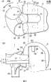
图1是本发明的实施方式1的人工膝关节的侧面图。FIG. 1 is a side view of an artificial knee joint according to
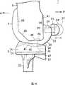
图2是本发明的实施方式1的人工膝关节的立体图。Fig. 2 is a perspective view of the artificial knee joint according to
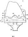
图3是本发明的实施方式1的人工膝关节的主视图。Fig. 3 is a front view of the artificial knee joint according to
图4是本发明的实施方式1的人工膝关节的后视图。Fig. 4 is a rear view of the artificial knee joint according to
图5是本发明的实施方式1的人工膝关节的俯视图。5 is a plan view of the artificial knee joint according to
图6是表示本发明的实施方式1的人工膝关节的弯曲动作的侧面图,表示弯曲角度0°(膝部的伸展时)的状态。6 is a side view showing the bending motion of the artificial knee joint according to
图7是表示本发明的实施方式1的人工膝关节的弯曲动作的侧面图,表示弯曲角度90°的状态。7 is a side view showing the bending motion of the artificial knee joint according to
图8是表示本发明的实施方式1的人工膝关节的弯曲动作的侧面图,表示弯曲角度180°(膝部的加深弯曲时)的状态。8 is a side view showing the bending motion of the artificial knee joint according to
图9是表示本发明的实施方式1的人工膝关节的内旋动作的俯视图(A)及侧面图(B)。9 is a plan view (A) and a side view (B) showing the internal rotation motion of the artificial knee joint according to
图10是本发明的实施方式2的人工膝关节的侧面图。Fig. 10 is a side view of the artificial knee joint according to
图11表示本发明的实施方式2的人工膝关节的两个方式(A、B)。FIG. 11 shows two forms (A, B) of the artificial knee joint according to
图12是本发明的实施方式3的人工膝关节的侧面图(A)、和比较例的侧面图(B)。12 is a side view (A) of an artificial knee joint according to
图13是本发明的实施方式4的人工膝关节的内侧的侧面图。Fig. 13 is a side view of the inside of the artificial knee joint according to
图14是本发明的实施方式4的人工膝关节的外侧的侧面图。Fig. 14 is a side view of the outside of the artificial knee joint according to
图15是本发明的实施方式4的人工膝关节的立体图。Fig. 15 is a perspective view of an artificial knee joint according to
图16是本发明的实施方式4的人工膝关节的主视图16 is a front view of the artificial knee joint according to
图17是表示本发明的实施方式4的人工膝关节的弯曲动作的内侧(A)及外侧(B)的端面图,表示弯曲角度90°的状态。17 is an end view of the inner side (A) and the outer side (B) of the bending motion of the artificial knee joint according to
图18是表示本发明的实施方式4的人工膝关节的弯曲动作的内侧(A)及外侧(B)的端面图,表示弯曲角度120°的状态。18 is an end view showing the inner side (A) and the outer side (B) of the bending motion of the artificial knee joint according to
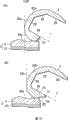
图19是表示本发明的实施方式4的人工膝关节的弯曲动作的内侧(A)及外侧(B)的端面图,表示弯曲角度150°的状态。19 is an end view showing the inner side (A) and the outer side (B) of the bending motion of the artificial knee joint according to
图20是表示本发明的实施方式4的人工膝关节的弯曲动作的内侧(A)及外侧(B)的端面图,表示弯曲角度180°的状态。20 is an end view showing the inner side (A) and the outer side (B) of the bending motion of the artificial knee joint according to
图中:1-人工膝关节;2-大腿骨部;21-凸轮部(连接部);22-凸块(顆);22a-内侧凸块;22b-外侧凸块;23-后端部;25-大腿骨关节面;25a-内侧大腿骨关节面;25b-外侧大腿骨关节面;3-胫骨部;31-胫骨托盘;4-插入盘;41-凸轮滑动移动面(后部弯曲部);45-胫骨关节面;45a-内侧胫骨关节面;45b-外侧胫骨关节面;52-大腿骨外侧的偏置关节面;6-大腿骨;61-残骨;7-骨切除面。In the figure: 1-artificial knee joint; 2-femoral part; 21-cam part (connecting part); 22-bump (piece); 22a-inside bump; 22b-outside bump; 23-rear end; 25-articular surface of femur; 25a-articular surface of medial femur; 25b-articular surface of lateral femur; 3-tibia; 31-tibial tray; ; 45-articular surface of tibia; 45a-articular surface of medial tibia; 45b-articular surface of lateral tibia; 52-offset articular surface of lateral femur;
具体实施方式Detailed ways
(实施方式1)(Embodiment 1)
如图1~图5所示,本发明的人工膝关节1包括:大腿骨部2,其固定在大腿骨的远位部;胫骨部3,其固定在胫骨的近位部。As shown in Figures 1 to 5, the
大腿骨部2具备:两个大腿骨关节面25,其弯曲而膨出;椭圆球状或大致圆柱状凸轮部21。The
胫骨部3包括:胫骨托盘31,其固定在胫骨的近位部;插入盘4,其固定在胫骨托盘31的上面。The
插入盘具备:与两个大腿骨关节面25分别抵接的两个胫骨关节面45;与凸轮部21抵接的凸轮滑动移动面41,并且与大腿骨部2直接接触而滑动移动。The insertion tray includes two tibial
本实施方式的人工膝关节1在膝部的伸展时是第一滑动移动状态,大腿骨关节面25在胫骨关节面45上滑动移动的同时与之抵接。若弯曲角度为90°~160°,则开始向第二滑动移动状态的转移,主要滑动移动面从大腿骨关节面25和胫骨关节面45变为凸轮部21和凸轮滑动移动面41。然后,在弯曲角度180°的膝部加深弯曲时,完全成为第二滑动移动状态,胫骨部3的骨切除面7和插入盘4的后端部偏置。The artificial knee joint 1 according to the present embodiment is in the first sliding movement state when the knee is extended, and the femoral
图1中,本发明实施方式中的人工膝关节1是弯曲角度0°时的侧面图,大腿骨6向垂直方向伸展。在此,人工膝关节1的大腿骨部2中,长长地向上方延伸的部分的前方(箭头A的方向)配置为前方,后端部23的配置为后方(箭头P的方向)而使用。In FIG. 1 , an artificial knee joint 1 according to an embodiment of the present invention is a side view at a bending angle of 0°, and a
大腿骨部2从侧面观察时为U字状大幅度弯曲的形状,安装为:在切掉大腿骨6的边位部之后,从前后方向夹住大腿骨6端部。在大腿骨部2的外表面形成有向前后方向延伸的两个凸块22(在此,凸块是指凸状部分),将其表面称为大腿骨关节面25。大腿骨关节面25形成为非常光滑,以在膝关节弯曲时可以容易地滑动移动。The
在大腿骨部2的后端部23,椭圆球状凸轮部21形成在两个凸块22之间。凸轮部21从大腿骨关节面25向后方P大大突出。At the
大腿骨部2的内侧是与大腿骨6接触的大腿骨固定面28。将大腿骨的病变的关节部分的骨切除,使大腿骨与大腿骨部2的大腿骨固定面28的尺寸形状匹配,从而对大腿骨整形(骨切除)。大腿骨6的后方P侧被切除为与称为大腿骨部2的骨切除面7的平面一致,此时,在大腿骨6的曲线和骨切除面7的交叉部分残留称为残骨61的突出部分。骨性接触中,多发生该残骨61和胫骨部3的接触,还有将大腿骨6整形以减少残骨61的突出的技术。然而,这样的整形处理需要高度技术,大部分的情况下,残留如图所示的形状的残骨61。The inner side of the
在大腿骨部2的大腿骨固定面28可以根据需要设置杆29。杆29具有:插入大腿骨从而稳定大腿骨部的固定状态的功能。大腿骨部2根据需要通过骨节(segment)固定在大腿骨。大腿骨部2由钛合金及钴-铬合金等生物体安全性高的金属或氧化铝及氧化锆等陶瓷形成。A
胫骨部3的插入盘4是使大腿骨部2滑动移动的部件。插入盘4的前后形成有两个凹部42(在此,“凹部”是指凹状部分),大腿骨部2的两个凸块22可以滑动移动。在各个凹部42的表面形成有非常光滑的胫骨关节面45,在与大腿骨部2的大腿骨关节面25之间可以进行光滑的滑动移动。The
在插入盘4的中央附近形成有脊(spine)44,并从在大腿骨部2的中央形成的前后延伸的狭缝27突出。脊44的后方P侧的表面连续于凸轮滑动移动面41。A
凸轮滑动移动面41形成为容纳大腿骨部2的凸轮部21的形状。凸轮滑动移动面41和凸轮部21设计为在人工膝关节1弯曲规定角度以上、例如90°以上的情况下接触。凸轮滑动移动面41和凸轮部21的表面都形成为光滑,可以进行光滑的滑动移动运动。插入盘44由超高分子量的聚乙烯(UHMWPE)形成。The
胫骨部3的胫骨托盘31的下面固定在胫骨的近位部,上面容纳插入盘4。胫骨托盘31具有:分散插入盘4从大腿骨部2接受的负荷,抑制应力集中在胫骨局部的功能。在固定胫骨托盘31时,首先切除胫骨近位部的病变的关节部分,其次,将胫骨托盘31的杆插入胫骨中。胫骨托盘的上表面大致水平地进行定位,通过螺栓或骨节将胫骨托盘31固定在胫骨。The lower surface of the
胫骨托盘31由钛合金及钴-铬合金等生物体安全性高的金属或氧化铝及氧化锆等陶瓷形成。The
本发明的人工膝关节1中,构成主要接触面的滑动移动状态以弯曲角度90°~160为边界,从第一滑动移动状态向第二滑动移动状态移动。该滑动移动状态下转移的角度为“偏置角度”。第一滑动移动状态中,由于以大面接接触,因此,适合像直立状态或步行状态一样对膝部施加大的负荷的情况。相对于此,第二滑动移动状态中,虽然对膝部施加大的负荷就不能一直支撑,但具有能够加深弯曲的优点。因此,偏置角度是均衡对膝部施加的负荷的程度、和骨性接触的避免的同时确定的。In the
若偏置角度小于90°,则不论对膝部施加的负荷多大,成为第二滑动移动状态,对膝部的安全性降低,因此不优选,另外,若大于160°,则在第一滑动移动状态的原来状态下直接发生骨性接触,因此不优选。If the offset angle is less than 90°, no matter how much the load applied to the knee is, it will become the second sliding movement state, and the safety of the knee will be reduced, so it is not preferable. In addition, if it is greater than 160°, the first sliding movement In the original state of the state, bony contact occurs directly, so it is not preferable.
如图6~图8所示,本发明的人工膝关节可以从弯曲角度0°弯曲至180°。该人工膝关节1的偏置角度是90°。As shown in Figures 6 to 8, the artificial knee joint of the present invention can be bent from a bending angle of 0° to 180°. The offset angle of the artificial knee joint 1 is 90°.
如图6所示,在弯曲角度为0°时,大腿骨关节面25和胫骨关节面45接触,形成第一滑动移动状态。该状态是例如在直立姿势或步行姿势下发生,对膝关节的负荷大。本发明的人工膝关节中,在弯曲角度为0°时,形成第一滑动移动状态,因此,能够稳定地支撑对膝关节施加的负荷。As shown in FIG. 6 , when the bending angle is 0°, the femoral
若弯曲角度成为偏置角度90°,则如图7所示,从第一滑动移动状态向凸轮部21和凸轮滑动移动面41接触的第二滑动移动状态转移。弯曲角度90°是在步行或上下台阶时可能发生的弯曲角度中最大的弯曲角度,对膝关节施加的负荷与弯曲角度0°时相比,非常小。因此,只要是通常生活中的动作程度,就能够以第二滑动移动状态支撑90°以上的弯曲角度下对膝关节施加的负荷。但是,在以加深弯曲状态进行重活的情况下,该程度不足够,需要设定偏置角度为更大的角度。When the bending angle becomes the offset angle of 90°, as shown in FIG. 7 , the first sliding state transitions to the second sliding state in which the
若将膝关节的弯曲角度增大为比人工膝关节的偏置角度90°大,则凸轮部21和凸轮滑动移动面41形成的第二滑动移动状态成为支配状态,若凸轮部21和凸轮滑动移动面41接触而滑动移动,则大腿骨部和胫骨部逐渐远离。与此同时,大腿骨关节面25和胫骨关节面45滑动移动的同时远离,消除第一滑动移动状态。这样一来,在比偏置角度大的弯曲角度下,主要的接触面从第一滑动移动状态向第二滑动移动状态转移。在第二滑动移动状态下,多是像坐在椅子的姿势或端坐的姿势一样对膝关节施加的负荷小的状态。因此,即使在耐负荷性低的第二滑动移动状态下,也几乎发生膝关节不稳定的问题。在该实施方式中,将偏置角度设定为约90°。偏置角度可以在90°~160°的范围内设定。If the bending angle of the knee joint is increased to be greater than the bias angle of 90° of the artificial knee joint, the second sliding movement state formed by the
还有,在弯曲角度为180°时,如图8所示可知,骨切除面7和插入盘4的后端缘部是完全远离的所谓的偏置状态。这表示:若使用本实施方式的人工膝关节进行膝关节的置换手术,则在膝关节的弯曲角度0°~180°大腿骨范围内,大腿骨6的残骨61和插入盘不接触,即骨性接触不发生。由此,本发明的人工膝关节实现以往的人工膝关节中不可能的弯曲角度0~180°的可动区域。Also, when the bending angle is 180°, as shown in FIG. 8 , the
然而,在膝关节的周围存在骨骼以外的周边组织,因此,实际上人的膝关节不能弯曲至180°。本发明中弯曲至180°不发生骨性接触的人工膝关节除了具有在能够弯曲至180°的直接的作用效果外,还具有避免位于膝关节周围的软部组织与残骨或人工膝关节接触而受到损伤的软部组织接触的间接的作用效果。However, peripheral tissues other than bone exist around the knee joint, and therefore, the human knee joint cannot actually bend to 180°. In addition to the direct effect of being able to bend to 180°, the artificial knee joint that is bent to 180° without bony contact in the present invention also has the function of avoiding the contact between the soft tissue around the knee joint and the residual bone or artificial knee joint. The indirect effect of contact with damaged soft tissue.
在以往的人工膝关节中,说到能够充分避免骨性接触,但在提供再现更自然的膝关节,不伴随别扭或疼痛的人工膝关节方面,避免软部组织接触也至关重要。在本发明的人工膝关节中,即使在最大幅度加深弯曲的端坐的状态(弯曲角度为约165度)下,弯曲角度也足够,因此,能够抑制软部组织接触。In conventional artificial knee joints, bony contact can be sufficiently avoided, but it is also important to avoid soft tissue contact in order to provide an artificial knee joint that reproduces a more natural knee joint without discomfort or pain. In the artificial knee joint of the present invention, the bending angle is sufficient even in the sitting upright state (bending angle is about 165 degrees) in which the bending is most greatly deepened, so soft tissue contact can be suppressed.
本发明的人工膝关节1中,优选在大腿骨部2偏置的第二滑动移动状态下,如下所述地调节偏置量,即:将从凸轮部21和凸轮滑动移动面41的接触点到插入盘4的后端部为止的距离a、和从凸轮部21和凸轮滑动移动面41的接触点到大腿骨部2的骨切除面7为止的距离b之间关系设为b>a。如图8所示,在骨切除面7和插入盘4的后端部最接近的状态、即弯曲角度180°的状态下,设定为b>a,由此使残骨和插入盘仅间隔(b-a)。由此,在弯曲角度0°~180°的范围内,能够可靠地避免骨性接触。In the
本发明的人工膝关节1,如图9所示,在偏置后的状态下,通过曲面的凸轮滑动移动面41收纳椭圆球状的凸轮部21,因此,能够进行大腿骨的回旋(在水平面内的大腿骨的回旋)。由此,本发明的人工膝关节在端坐时不会妨碍大腿骨欲稍微内旋的移动,能够再现自然的膝的弯曲运动。在该例中,残骨61和插入盘4以回旋角度θ=25°接触,因此,能够进行回旋角度θ=0~25°的内旋及外旋。The
本发明的人工膝关节1具备凸轮部21和凸轮滑动移动面41,由此在加深弯曲状态下形成第二滑动移动状态,进而,大腿骨部2设为偏置,能够实现以往的人工膝关节中不可能的弯曲角度0~180°的可动区域。The
(实施方式2)(Embodiment 2)
在本实施方式中,与实施方式1相同地,是包括大腿骨部2和胫骨部3的人工膝关节,但其特征在于,凸轮部21能够滑动地固定在大腿骨部2的后端部23,通过改变凸轮部21从大腿骨关节面25突出的突出量,能够调节偏置量。In the present embodiment, similar to
如图10所示,在大腿骨部2的后端部23形成有凸轮用孔26,凸轮部21将凸轮轴部24插入该凸轮用孔26中而被固定。凸轮轴部24和凸轮用孔26通过在凸轮轴部24的表面和凸轮用孔26的内表面形成卡合机构,或使用独立于其的卡合用部件,可靠地进行固定。另外,凸轮轴部24通过解除固定状态,能够改变凸轮用孔26内的位置,例如,能够将凸轮轴部24移动至凸轮轴部24’的位置。在这种状态下,通过将凸轮轴部24’固定在凸轮用孔26,能够以凸轮部21突出至凸轮部21’的状态使用。As shown in FIG. 10 , a
在本实施方式的人工膝关节1中,如图11所示,在大腿骨部2的凸轮部21、和在胫骨部3的插入盘4形成的凸轮滑动移动面41滑动移动的第二滑动移动状态下,可以选择凸轮部21不突出的第二滑动移动状态(A)、和凸轮部21’突出的第二滑动移动状态(B)。在图11(B)的人工膝关节1中,与图11(A)的结构相比,大腿骨6的残骨61、和插入盘4的端部的距离变大,因此,适合容易发生骨性接触的患者。另外,通过选择凸轮部21或凸轮部21’的位置,以使更接近病变前的膝关节的状态,从而能够减小置换为人工膝关节1后的患者的不协调感。In the
在本实施方式中,示出了能够改变凸轮部21、21’的位置为两个阶段的人工膝关节,但进而也能够设为可将凸轮部21的位置变更为多个阶段、或无阶段的方式。In the present embodiment, an artificial knee joint capable of changing the positions of the
(实施方式3)(Embodiment 3)
本实施方式,与实施方式1相同地,是包括大腿骨部2和胫骨部3的人工膝关节1,但其特征在于,插入盘4在与凸轮滑动移动面对应的中央位置的背面侧具备向下方倾斜的突出部,胫骨托盘具有接受向下方倾斜的突出部的凹部。The present embodiment is the artificial knee joint 1 including the
本发明的人工膝关节1中,通过第一滑动移动状态、和第二滑动移动状态两个滑动移动状态能够进行膝盖的弯曲,由于重复这些滑动移动,磨损插入盘4。因此,需要设定插入盘4的厚度以使胫骨关节面45和凸轮滑动移动面41的下侧成为考虑了磨损的规定的厚度t以上。In the
图12(B)是将插入盘4按以往的设计手法形成的人工膝关节1。在本发明的人工膝关节1中,凸轮滑动移动面41被挖去大块,因此,为了凸轮滑动移动面41下部的厚度t,插入盘4的厚度T’与t相比,非常大。Fig. 12(B) shows the artificial knee joint 1 formed by inserting the
相对于此,本实施方式的人工膝关节1,如图12所示,通过将突出部47形成在凸轮滑动移动背面侧,能够确保凸轮滑动移动面42的下侧的厚度t。在该实施方式中,能够将排除突出部47的插入盘4的厚度T抑制至与规定的厚度t相同的程度。由此,在埋设胫骨部3时切除胫骨的长度能够缩短大约(T’-T)程度,因此,具有抑制人工膝关节的置换手术后的骨折的效果。还有,需要根据突出部47的外形状切除部分胫骨,但能够使该切除的骨的量小于在插入盘4的厚度厚的情况下除去的骨的量。On the other hand, in the
只要能够确保凸轮滑动移动面下部的厚度,就能够将突出部47形成为各种形状,例如,能够形成为立方体形状、球状、或椭圆球状。尤其,突出部47的形状,如图12所示,优选向下方倾斜的形状。这是因为所述形状为在根据突出部47的外形状切除胫骨时能够容易切除的形状,而且能够减小突出部47的容量,因此,能够减小切除的骨的量。As long as the thickness of the lower portion of the cam sliding surface can be ensured, the protruding
胫骨托盘31中,与插入盘4的突出部47的形状对应地形成有凹部37,在将插入盘4固定于胫骨托盘31时,将突出部47嵌入凹部37中。该胫骨托盘31的凹部37接受对插入盘4的突出部47施加的负荷,将负荷分散在胫骨托盘31整体上,因此,能够避免在胫骨的局部集中应力,具有抑制骨折的危险的效果。In the
另外,在胫骨托盘31的背面侧形成有与凹部37的形状对应的凸部。由此,能够将胫骨托盘31的凹部37形成为大致恒定的壁厚。通过将胫骨托盘31形成为必要最小限度的恒定的壁厚,能够在维持应力分散功能的状态减少胫骨的骨切除量。In addition, a convex portion corresponding to the shape of the
(实施方式4)(Embodiment 4)
本实施方式1的人工膝关节1,如图13~图16所示,包括:固定在大腿骨6的远位部的大腿骨部2、和固定在胫骨的近位部的胫骨部3。The artificial knee joint 1 according to
大腿骨部2具备:弯曲而膨出的两个大腿骨关节面(内侧大腿骨关节面25a和外侧大腿骨关节面25b)、连接两个大腿骨关节面的后端部的连接部21(在该例中为凸轮部)、和形成在外侧大腿骨关节面25b的后端部的偏置用凹部曲面(称为大腿骨外侧偏置曲面52)。在从大腿骨外侧偏置曲面52向上方延伸的前端部形成有鸟嘴状平坦地延伸的偏置前端部51。The
胫骨部3包括:胫骨托盘31、和固定在胫骨托盘31的上表面的插入盘4。The
插入盘4具备:分别与内侧大腿骨关节面25a及外侧大腿骨关节面25b接触的两个胫骨关节面(内侧胫骨关节面45a和外侧胫骨关节面45b);连接部21不能超越的高度的脊44;以使连接部21滑动移动地与连接部21抵接的方式形成在脊44的后方P侧的后部曲面41(该例中为凸轮滑动移动面);以使大腿骨外侧偏置曲面52滑动移动的方式形成在插入盘4的后端缘部的胫骨外侧偏置曲面82。The
本实施方式的人工膝关节1是在膝部的伸展时,外侧及内侧的大腿骨关节面25a、25b以在外侧及内侧的胫骨关节面45a、45b滑动移动的方式与该外侧及内侧的胫骨关节面45a、45b抵接的第一滑动移动状态。若膝关节成为90°~160°的弯曲角度,则第一滑动移动状态中基于外侧大腿骨关节面25b及外侧胫骨关节面45b的外侧的关节面的抵接状态向作为大腿骨外侧偏置曲面和胫骨外侧偏置曲面的能够滑动移动的抵接状态的第三滑动移动状态转移。在大致相同的弯曲角度下,大腿骨部2的连接部21、和插入盘4的脊44的后部曲面41能够滑动移动地抵接,构成第四滑动移动状态。还有,在弯曲角度180°的膝部加深弯曲时,第三及第四滑动移动状态共存,胫骨部3的骨切除面7和插入盘4的后端部偏置。In the
图13及图14是本实施方式的右膝用人工膝关节1的弯曲角度0°时的侧面图,图13是从人工膝关节1的内侧观察的侧面图,图14是从人工膝关节1的外侧观察的侧面图。这些图中,大腿骨6向垂直上方延伸。在此,人工膝关节1的大腿骨部2中,长长地向上方延伸的部分配置为前方(箭头A方向),后端部配置为后方(箭头P方向)而使用。13 and 14 are side views of the artificial knee joint 1 for the right knee according to this embodiment at a bending angle of 0°. FIG. 13 is a side view viewed from the inside of the artificial knee joint 1, and FIG. Side view of the lateral view. In these figures, the
大腿骨部2是从侧面观察时U字状大大弯曲的形状,在切除大腿骨6的边位部后,从前后夹入大腿骨6的端部地安装大腿骨部2。在大腿骨部2的外表面形成有向前后方向延伸的内侧凸块22a及外侧凸块22b,将其表面称为内侧大腿骨关节面25a及外侧大腿骨关节面25b。内侧及外侧大腿骨关节面25a、25b形成为非常光滑,以在膝关节的弯曲时能够容易地滑动移动。The
在大腿骨部2的后端部23,椭圆球状的连接部21形成在两个凸块22a、22b之间。在该例中,连接部21形成为从大腿骨关节面25向后方P突出的凸轮部21。然而,连接部21不限于该方式,可以利用圆柱状、椭圆柱状、球状等具有适合滑动移动的外形的连接部。At the
大腿骨部2的内侧是与大腿骨6接触的大腿骨固定面28。将大腿骨的病变的关节部分的骨切除,使大腿骨与大腿骨部2的大腿骨固定面28的尺寸形状匹配,从而对大腿骨整形(骨切除)。大腿骨6的后方P侧被切除为与称为大腿骨部2的骨切除面7的平面一致,此时,在大腿骨6的曲线和骨切除面7的交叉部分残留称为残骨61的突出部分。骨性接触中,多发生该残骨61和胫骨部3的接触,还有将大腿骨6整形以减少残骨61的突出的技术。然而,这样的整形处理需要高度技术,大部分的情况下,残留如图所示的形状的残骨61。The inner side of the
在大腿骨部2的大腿骨固定面28可以根据需要设置杆29。杆29具有:插入大腿骨从而稳定大腿骨部的固定状态的功能。大腿骨部2根据需要通过骨节固定在大腿骨。大腿骨部2由钛合金及钴-铬合金等生物体安全性高的金属或氧化铝及氧化锆等陶瓷形成。A
胫骨部3的插入盘4是使大腿骨部2滑动移动的部件。插入盘4形成有向前后延伸的内侧凹部42a及外侧凹部42a两个凹部42(在此,“凹部”是指凹状部分),大腿骨部2的内侧凸块22a及外侧凸块22a两个凸块可以滑动移动。在内侧凸块22a及外侧凸块22a的表面形成有非常光滑的内侧胫骨关节面45及外侧胫骨关节面45b,在与大腿骨部2的内侧大腿骨关节面25a及外侧大腿骨关节面25b之间可以进行光滑的滑动移动。The
在插入盘4的中央附近形成有脊44,并从在大腿骨部2的中央形成的前后延伸的狭缝27突出。脊44的后方P侧的表面形成有滑动曲面41,以使连接部21滑动移动。A
脊44的后部曲面41形成为容纳大腿骨部2的连接部21的形状。后部曲面41和连接部21设计为在人工膝关节1弯曲规定角度以上、例如90°以上的情况下接触。后部曲面41和连接部21的表面都形成为光滑,以可以进行光滑的滑动移动运动。插入盘44由超高分子量的聚乙烯(UHMWPE)形成。The rear
胫骨部3的胫骨托盘31的下面固定在胫骨的近位部,上面容纳插入盘4。胫骨托盘31具有:分散插入盘4从大腿骨部2接受的负荷,抑制应力集中在胫骨局部的功能。在固定胫骨托盘31时,首先切除胫骨近位部的病变的关节部分,其次,将胫骨托盘31的杆插入胫骨中。胫骨托盘的上表面大致水平地进行定位,通过螺栓或骨节将胫骨托盘31固定在胫骨。The lower surface of the
胫骨托盘31由钛合金及钴-铬合金等生物体安全性高的金属或氧化铝及氧化锆等陶瓷形成。The
本发明的人工膝关节1中,构成主要接触面的滑动移动状态以弯曲角度90°~160为边界,从第一滑动移动状态向第三滑动移动状态移动。该滑动移动状态下转移的角度为“偏置角度”。第一滑动移动状态中,由于以大面接接触,因此,适合像直立状态或步行状态一样对膝部施加大的负荷的情况。相对于此,与第三滑动移动状态相比,稳定性低,不能一直支撑膝部承受大的负荷。取而代之,第三实施方式中,具有能够加深弯曲的优点。因此,偏置角度是均衡对膝部施加的负荷的程度、和骨性接触的避免的同时确定的。In the
若偏置角度小于90°,则不论对膝部施加的负荷多大,成为第三滑动移动状态,对膝部的安全性降低,因此不优选,另外,若大于160°,则在第一滑动移动状态的原来状态下直接发生骨性接触,因此不优选。If the offset angle is less than 90°, no matter how much the load applied to the knee is, it will be in the third sliding movement state, and the safety on the knee will be reduced, so it is not preferable. If it is greater than 160°, the first sliding movement will be In the original state of the state, bony contact occurs directly, so it is not preferable.
本发明的人工膝关节如图13、图14、图17~图20所示,能够从弯曲角度0°弯曲至180°。在此,图17~图20的(A)是内侧的端面图,(B)是外侧的端面图。该人工膝关节1的偏置角度是90°。The artificial knee joint of the present invention can be bent from a bending angle of 0° to 180° as shown in Fig. 13 , Fig. 14 , and Fig. 17 to Fig. 20 . Here, (A) of FIGS. 17-20 is an inside end view, (B) is an outside end view. The offset angle of the artificial knee joint 1 is 90°.
在图13(内侧的侧面图)及图14(外侧的侧面图)所示的弯曲角度0°(伸展膝盖的状态)下,内侧大腿骨关节面25a及外侧大腿骨关节面25b、内侧胫骨关节面45a及外侧胫骨关节面45b分别接触,形成第一滑动移动状态。该状态例如发生直立姿势或步行姿势下发生,对膝关节施加的负荷大。本发明的人工膝关节在弯曲角度0°时,形成第一滑动移动状态,因此,能够稳定地支撑对膝关节施加的大的负荷。Under the bending angle 0° (extending the knee) shown in Fig. 13 (side view of the inside) and Fig. 14 (side view of the outside), the medial femoral
若弯曲角度成为偏置角度90°,则图17(B)所示的外侧的滑动移动状态从第一滑动移动状态向大腿骨外侧偏置曲面52和胫骨外侧偏置曲面82抵接的第三滑动移动状态开始转移。相对于此,图17(A)所示的内侧的滑动移动状态不变化。If the bending angle becomes an offset angle of 90°, the outer sliding state shown in FIG. Swipe to move the state to start transferring. On the other hand, the slide movement state of the inner side shown in FIG. 17(A) does not change.
连接部21和后部曲面41抵接,形成第四滑动移动状态。The connecting
若将膝关节的弯曲角度增大为比人工膝关节的偏置角度90°大,则如图18(B)及图19(B)所示,如下所述地进行,即:首先,大腿骨外侧偏置曲面52嵌入胫骨外侧偏置曲面82,进而偏置前端部51卡在胫骨外侧偏置曲面82的后方。此时,外侧大腿骨关节面25b向后方P侧仅偏置偏置前端部51的厚度程度。该外侧的偏置中,与第四滑动移动状态(未图示的连接部21和脊44后部的曲面41的滑动移动状态)联动,如图18(A)及图19(A)所示,成为将内侧的内侧大腿骨关节面25a向前方偏置的结果。通过使大腿骨部2的内侧和外侧向不同的方向偏置,发生大腿骨部2的回旋,尤其当内侧向前方A,外侧向后方P偏置的情况下,发生大腿骨部2的内旋。这样,本实施方式的人工膝关节1随着弯曲角度进展,能够实现与健康的膝关节相同的内旋。If the bending angle of the knee joint is increased to be larger than the offset angle of 90° of the artificial knee joint, as shown in Fig. 18(B) and Fig. 19(B), it is carried out as follows: The lateral offset
如图20所示,若弯曲为180°,则外侧(图20(B))仅偏置偏置前端部51的厚度程度,骨切除面7和插入盘4的后端部间隔。相对于此,内侧(图20(A))与外侧相比,向前方A偏置,因此,与外侧相比,偏置量少。关于内侧,在弯曲角度180°以下且存在发生骨性接触的情况下,能够增加大腿骨部2的后端部23的厚度,使骨切除面7和插入盘4的后端缘部远离。As shown in FIG. 20, if the bending is 180°, the outer side (FIG. 20(B)) is only offset by the thickness of the
若使用本实施方式的人工膝关节进行膝关节的置换手术,则表示在膝关节的弯曲角度0°~180°的范围内,大腿骨6的残骨61和插入盘不接触,即不发生骨性接触。由此,本发明的人工膝关节能够实现在以往的人工膝关节中不能的弯曲角度0~180°的可动区域。If the artificial knee joint of this embodiment is used to perform knee joint replacement surgery, it means that the
然而,在膝关节的周围存在骨骼以外的周边组织,因此,实际上人的膝关节不能弯曲至180°。本发明中弯曲至180°不发生骨性接触的人工膝关节除了具有在能够弯曲至180°的直接的作用效果外,还具有避免位于膝关节周围的软部组织与残骨或人工膝关节接触而受到损伤的软部组织接触的间接的作用效果。However, peripheral tissues other than bone exist around the knee joint, and therefore, the human knee joint cannot actually bend to 180°. In addition to the direct effect of being able to bend to 180°, the artificial knee joint that is bent to 180° without bony contact in the present invention also has the function of avoiding the contact between the soft tissue around the knee joint and the residual bone or artificial knee joint. The indirect effect of contact with damaged soft tissue.
在以往的人工膝关节中,说到能够充分避免骨性接触,但在提供再现更自然的膝关节,不伴随别扭或疼痛的人工膝关节方面,避免软部组织接触也至关重要。在本发明的人工膝关节中,即使在最大幅度加深弯曲的端坐的状态(弯曲角度为约165度)下,弯曲角度也足够,因此,能够抑制软部组织接触。In conventional artificial knee joints, bony contact can be sufficiently avoided, but it is also important to avoid soft tissue contact in order to provide an artificial knee joint that reproduces a more natural knee joint without discomfort or pain. In the artificial knee joint of the present invention, the bending angle is sufficient even in the sitting upright state (bending angle is about 165 degrees) in which the bending is most greatly deepened, so soft tissue contact can be suppressed.
进而,如图18~图20(A)的第三滑动移动状态明确可知,偏置前端部51卡在插入盘4的后方。由此,能够抑制脊44的局部的异常磨损。通常,若膝关节的弯曲加深,则发生大腿骨部2欲向前方A移动的应力。在以往的人工膝关节中,由连接部21和脊44后部的曲面41承受该应力的全部,因此,在后部曲面41上发生异常磨损。相对于此,在本实施方式的人工膝关节中,偏置前端部51也承受向大腿骨部的前方A方向的应力,因此,分散施加在后部曲面41上的应力,从而能够抑制异常磨损。Furthermore, as is clear from the third sliding movement state shown in FIGS. 18 to 20(A), the offset
作为该实施方式的变形例,其是一种人工膝关节,其特征在于,进而,大腿骨部具备在内侧大腿骨关节面的后端部形成的凹状大腿骨内侧偏置曲面(未图示),且在插入盘具备大腿骨内侧偏置曲面滑动移动的胫骨内侧偏置曲面,在90°~160°的弯曲角度中,第一滑动移动状态下的内侧的关节面的抵接向大腿骨内侧偏置曲面在胫骨内侧偏置曲面上滑动移动地抵接的第三滑动移动状态转移。As a modified example of this embodiment, it is an artificial knee joint characterized in that, furthermore, the femoral portion has a concave femoral medial offset curved surface (not shown) formed at the rear end portion of the medial femoral articular surface. , and the medial femoral offset curved surface on the insertion plate is equipped with a medial femoral offset curved surface that slides and moves, and at a bending angle of 90° to 160°, the abutment of the medial articular surface in the first sliding movement state is toward the inner side of the femur The third sliding movement state in which the offset curved surface slidingly abuts against the tibial medial offset curved surface is transferred.
即,不仅在大腿骨部2的外侧,而且在大腿骨部的内侧也形成偏置前端部51,从而能够形成为内侧及外侧两者偏置的人工膝关节。在该变形例中,偏置前端部51和插入盘4的后端部卡住的部位有两处,因此,能够进一步分散大腿骨部欲向前方A移动的应力,故优选。内侧及外侧的偏置前端部还可以形成为同一尺寸形状,但优选形成为不同的尺寸形状,实现自然的内旋。That is, the offset
若大腿骨部2的连接部21为从大腿骨关节面25不突出的椭圆球状或大致圆柱状,则能够减小收纳连接部21的脊44后部的曲面41的深度。这抑制插入盘4的厚度的增加,因此,能够减小胫骨的骨切除量。If the
相反,也可以将大腿骨部2的连接部21形成为从大腿骨关节面25突出的椭圆球状或大致圆柱状的凸轮部21,将插入盘4的脊44的后部曲面41形成为使凸轮部21滑动移动的滑动移动面41。若将连接部设为凸轮部,则在第四滑动移动状态下抵接面的面积增大,因此,抑制脊44后部的异常磨损,能够得到可长期使用的人工膝关节。On the contrary, it is also possible to form the connecting
本发明的人工膝关节能够进行在以往的人工膝关节中不能的加深弯曲,形成为理论上能够弯曲至180°的膝关节,不仅能够避免膝盖的骨性接触,而且能够避免软部组织接触。进而,本发明的人工膝关节能够与用健康的膝盖自然地站立的情况相同地实现大腿骨的内旋。由此,作为进行膝关节的置换手术的患者来说,能够得到不协调感少的人工膝关节。The artificial knee joint of the present invention can perform deep bending that cannot be performed in conventional artificial knee joints, and can be formed into a knee joint that can theoretically bend up to 180°, and can avoid not only bony contact of the knee, but also soft tissue contact. Furthermore, the artificial knee joint of the present invention can realize internal rotation of the femur similarly to the case of standing naturally with a healthy knee. As a result, an artificial knee joint with less discomfort can be obtained for a patient undergoing knee joint replacement surgery.
另外,本发明的人工膝关节不易引起部件的异常磨损,因此,能够长期使用,可以说对再而三不可避免地进行置换手术的患者来说是非常优选的人工膝关节。另外,对抑制各个部分的骨切除量进行了研究,因此,也适合骨量减少的患者。In addition, the artificial knee joint of the present invention is less likely to cause abnormal wear of parts, and therefore can be used for a long period of time. It can be said that it is a very preferable artificial knee joint for patients who inevitably undergo repeated replacement surgery. In addition, it is also suitable for patients with osteopenia because it has been studied to suppress the amount of bone resection in each part.
Claims (8)
Applications Claiming Priority (3)
| Application Number | Priority Date | Filing Date | Title |
|---|---|---|---|
| JP2005205888 | 2005-07-14 | ||
| JP205888/2005 | 2005-07-14 | ||
| PCT/JP2006/313986WO2007007841A1 (en) | 2005-07-14 | 2006-07-13 | Artificial knee joint |
Publications (2)
| Publication Number | Publication Date |
|---|---|
| CN101222886A CN101222886A (en) | 2008-07-16 |
| CN101222886Btrue CN101222886B (en) | 2012-05-30 |
Family
ID=37637221
Family Applications (1)
| Application Number | Title | Priority Date | Filing Date |
|---|---|---|---|
| CN2006800257599AExpired - Fee RelatedCN101222886B (en) | 2005-07-14 | 2006-07-13 | Artificial knee joint |
Country Status (4)
| Country | Link |
|---|---|
| US (1) | US7955394B2 (en) |
| JP (1) | JP4887292B2 (en) |
| CN (1) | CN101222886B (en) |
| WO (1) | WO2007007841A1 (en) |
Families Citing this family (61)
| Publication number | Priority date | Publication date | Assignee | Title |
|---|---|---|---|---|
| US9301845B2 (en) | 2005-06-15 | 2016-04-05 | P Tech, Llc | Implant for knee replacement |
| US7955394B2 (en)* | 2005-07-14 | 2011-06-07 | Saga University | Artificial knee joint |
| CA2641966C (en)* | 2005-12-15 | 2016-11-22 | Zimmer, Inc. | Distal femoral knee prostheses |
| US8142510B2 (en)* | 2007-03-30 | 2012-03-27 | Depuy Products, Inc. | Mobile bearing assembly having a non-planar interface |
| US8366783B2 (en) | 2007-08-27 | 2013-02-05 | Samuelson Kent M | Systems and methods for providing deeper knee flexion capabilities for knee prosthesis patients |
| AU2014202611B2 (en)* | 2007-08-27 | 2017-05-25 | Kent M. Samuelson | Systems and methods for providing deeper knee flexion capabilities for knee prosthesis patients |
| US9872774B2 (en) | 2007-08-27 | 2018-01-23 | Connor E. Samuelson | Systems and methods for providing a femoral component having a modular stem |
| US9107769B2 (en) | 2007-08-27 | 2015-08-18 | Kent M. Samuelson | Systems and methods for providing a femoral component |
| US8382846B2 (en) | 2007-08-27 | 2013-02-26 | Kent M. Samuelson | Systems and methods for providing deeper knee flexion capabilities for knee prosthesis patients |
| US8273133B2 (en) | 2007-08-27 | 2012-09-25 | Samuelson Kent M | Systems and methods for providing deeper knee flexion capabilities for knee prosthesis patients |
| US10213826B2 (en) | 2007-08-27 | 2019-02-26 | Connor E Samuelson | Systems and methods for providing prosthetic components |
| KR100904087B1 (en)* | 2008-01-08 | 2009-06-23 | 주식회사 코렌텍 | Artificial knee joint with curvature in bearing member |
| US8202323B2 (en)* | 2008-07-16 | 2012-06-19 | Depuy Products, Inc. | Knee prostheses with enhanced kinematics |
| JP5335458B2 (en)* | 2009-01-30 | 2013-11-06 | 京セラメディカル株式会社 | Artificial knee joint |
| JP5419490B2 (en)* | 2009-02-20 | 2014-02-19 | 京セラメディカル株式会社 | Artificial knee joint |
| CN105380733B (en)* | 2009-03-27 | 2021-09-14 | 史密夫和内修整形外科股份公司 | Artificial knee joint |
| CA2756226C (en)* | 2009-03-27 | 2017-01-24 | Smith & Nephew Orthopaedics Ag | Artificial knee joint |
| CN102497837B (en)* | 2009-07-27 | 2015-12-02 | 托马斯·P·安瑞尔基 | Knee joint replacement system |
| US8568485B2 (en)* | 2009-08-11 | 2013-10-29 | Imds Corporation | Articulating trials for prosthetic implants |
| US8496666B2 (en) | 2009-08-11 | 2013-07-30 | Imds Corporation | Instrumentation for mobile bearing prosthetics |
| US8998997B2 (en) | 2009-08-11 | 2015-04-07 | Michael D. Ries | Implantable mobile bearing prosthetics |
| US8382848B2 (en)* | 2009-08-11 | 2013-02-26 | Imds Corporation | Position adjustable trial systems for prosthetic implants |
| US9095453B2 (en)* | 2009-08-11 | 2015-08-04 | Michael D. Ries | Position adjustable trial systems for prosthetic implants |
| US8900315B2 (en)* | 2009-11-16 | 2014-12-02 | New York Society For The Ruptured And Crippled Maintaining The Hospital For Special Surgery | Constrained condylar knee device |
| US8764840B2 (en) | 2010-07-24 | 2014-07-01 | Zimmer, Inc. | Tibial prosthesis |
| CN106073949B (en)* | 2010-07-24 | 2018-12-14 | 捷迈有限公司 | tibial prosthesis |
| ES2632995T3 (en) | 2010-07-24 | 2017-09-18 | Zimmer, Inc. | Asymmetric tibia components for a knee prosthesis |
| EP2606856A4 (en)* | 2010-08-19 | 2014-01-22 | Kyocera Medical Corp | Artificial knee joint |
| US8591594B2 (en) | 2010-09-10 | 2013-11-26 | Zimmer, Inc. | Motion facilitating tibial components for a knee prosthesis |
| CA2993979A1 (en) | 2010-09-10 | 2012-03-15 | Zimmer Gmbh | Femoral prosthesis with medialized patellar groove |
| GB2483492A (en) | 2010-09-10 | 2012-03-14 | John Goodfellow | Femoral prosthetic component with extension |
| JP5688281B2 (en) | 2010-12-10 | 2015-03-25 | 京セラメディカル株式会社 | Artificial knee joint |
| US8603101B2 (en) | 2010-12-17 | 2013-12-10 | Zimmer, Inc. | Provisional tibial prosthesis system |
| US8709092B2 (en) | 2011-02-16 | 2014-04-29 | Genesis Medical Devices, LLC | Periprosthetic fracture management enhancements |
| DE102011001885B4 (en)* | 2011-04-07 | 2025-03-27 | Aesculap Ag | Knee joint endoprosthesis |
| AU2012271243B2 (en)* | 2011-06-16 | 2015-05-07 | Zimmer, Inc. | Femoral component for a knee prosthesis with improved articular characteristics |
| US9060868B2 (en) | 2011-06-16 | 2015-06-23 | Zimmer, Inc. | Femoral component for a knee prosthesis with bone compacting ridge |
| US9308095B2 (en) | 2011-06-16 | 2016-04-12 | Zimmer, Inc. | Femoral component for a knee prosthesis with improved articular characteristics |
| US8551179B2 (en) | 2011-06-16 | 2013-10-08 | Zimmer, Inc. | Femoral prosthesis system having provisional component with visual indicators |
| US8932365B2 (en) | 2011-06-16 | 2015-01-13 | Zimmer, Inc. | Femoral component for a knee prosthesis with improved articular characteristics |
| EP2726021B1 (en)* | 2011-06-30 | 2015-11-04 | DePuy (Ireland) | Posterior stabilized orthopaedic prosthesis assembly |
| DE102011054731A1 (en)* | 2011-10-21 | 2013-04-25 | Aesculap Ag | Tibia implant for knee joint endoprosthesis, has implant body, where bottom side of implant body is microscopically uneven and has two bone contact surface areas inclined relative to each other |
| EP3175824B1 (en) | 2011-11-18 | 2019-01-02 | Zimmer, Inc. | Tibial bearing component for a knee prosthesis with improved articular characteristics |
| ES2585838T3 (en) | 2011-11-21 | 2016-10-10 | Zimmer, Inc. | Tibial base plate with asymmetric placement of fixing structures |
| US8808387B2 (en)* | 2012-01-26 | 2014-08-19 | Epic Ortho, LLC | Prosthetic joint |
| IN2014DN07145A (en) | 2012-01-30 | 2015-04-24 | Zimmer Inc | |
| EP2882376B1 (en)* | 2012-08-09 | 2017-06-14 | Peter Stanley Walker | Total knee replacement substituting function of anterior cruciate ligament |
| FR3008606B1 (en)* | 2013-07-19 | 2017-01-06 | Biomet | TOTAL KNEE PROSTHESIS |
| CN103385771A (en)* | 2013-08-01 | 2013-11-13 | 上海晟实医疗器械科技有限公司 | Knee joint tibia support with asymmetrical structure |
| US9925052B2 (en) | 2013-08-30 | 2018-03-27 | Zimmer, Inc. | Method for optimizing implant designs |
| JP2014057858A (en)* | 2013-09-13 | 2014-04-03 | Kyocera Medical Corp | Artificial knee joint |
| US10130375B2 (en) | 2014-07-31 | 2018-11-20 | Zimmer, Inc. | Instruments and methods in performing kinematically-aligned total knee arthroplasty |
| JP6305268B2 (en)* | 2014-08-07 | 2018-04-04 | スミス・アンド・ネフュー・オルソペディクス・アーゲー | Artificial knee joint |
| WO2017053196A1 (en) | 2015-09-21 | 2017-03-30 | Zimmer, Inc. | Prosthesis system including tibial bearing component |
| EP3355834B1 (en) | 2015-09-29 | 2023-01-04 | Zimmer, Inc. | Tibial prosthesis for tibia with varus resection |
| CN106726015A (en)* | 2016-12-30 | 2017-05-31 | 广东工业大学 | A kind of mould for making knee joint bone cement spacer tibial component |
| US10675153B2 (en) | 2017-03-10 | 2020-06-09 | Zimmer, Inc. | Tibial prosthesis with tibial bearing component securing feature |
| WO2018208612A1 (en) | 2017-05-12 | 2018-11-15 | Zimmer, Inc. | Femoral prostheses with upsizing and downsizing capabilities |
| US11426282B2 (en) | 2017-11-16 | 2022-08-30 | Zimmer, Inc. | Implants for adding joint inclination to a knee arthroplasty |
| US10835380B2 (en) | 2018-04-30 | 2020-11-17 | Zimmer, Inc. | Posterior stabilized prosthesis system |
| TWI786139B (en)* | 2018-06-22 | 2022-12-11 | 財團法人工業技術研究院 | Artificial joint |
Citations (2)
| Publication number | Priority date | Publication date | Assignee | Title |
|---|---|---|---|---|
| US4808185A (en)* | 1986-02-07 | 1989-02-28 | Penenberg Brad L | Tibial prosthesis, template and reamer |
| CN1403064A (en)* | 2002-09-26 | 2003-03-19 | 上海市第六人民医院 | Rolling artificial knee joint |
Family Cites Families (25)
| Publication number | Priority date | Publication date | Assignee | Title |
|---|---|---|---|---|
| US4298992A (en)* | 1980-01-21 | 1981-11-10 | New York Society For The Relief Of The Ruptured And Crippled | Posteriorly stabilized total knee joint prosthesis |
| US4634444A (en)* | 1984-02-09 | 1987-01-06 | Joint Medical Products Corporation | Semi-constrained artificial joint |
| JPH0387344A (en)* | 1989-08-30 | 1991-04-12 | Nkk Corp | Method for uniformizing plating coat in continuous molten plating |
| US5282869A (en) | 1990-10-24 | 1994-02-01 | Kyocera Corporation | Artificial knee joint |
| JP2981917B2 (en) | 1990-10-24 | 1999-11-22 | 京セラ株式会社 | Artificial knee joint |
| US5358527A (en)* | 1991-03-22 | 1994-10-25 | Forte Mark R | Total knee prosthesis with resurfacing and posterior stabilization capability |
| JP3469972B2 (en) | 1995-09-29 | 2003-11-25 | 京セラ株式会社 | Artificial knee joint |
| JP3667909B2 (en)* | 1996-11-29 | 2005-07-06 | 京セラ株式会社 | Knee prosthesis |
| GB2336317B (en)* | 1996-12-09 | 2001-02-14 | Jacques Afriat | Complete knee joint prosthesis |
| JP3779788B2 (en) | 1997-01-17 | 2006-05-31 | 株式会社日立メディコ | Digital radiography equipment |
| US6123729A (en) | 1998-03-10 | 2000-09-26 | Bristol-Myers Squibb Company | Four compartment knee |
| US6443991B1 (en)* | 1998-09-21 | 2002-09-03 | Depuy Orthopaedics, Inc. | Posterior stabilized mobile bearing knee |
| FR2791553B1 (en)* | 1999-04-01 | 2001-07-06 | Merck Biomaterial France | ANTERO-POSTERO-STABILIZED KNEE PROSTHESIS |
| ES2368422T3 (en)* | 2001-04-17 | 2011-11-17 | Exactech, Inc. | ARTICULATION OF KNEE PROTESIC. |
| JP3087344U (en) | 2002-01-17 | 2002-08-02 | 純 八野田 | W-shaped femoral artificial knee joint |
| DE10201744B3 (en)* | 2002-01-18 | 2004-02-26 | Eska Implants Gmbh & Co. | Knee joint endoprosthesis used as a total replacement for a knee joint comprises a stop arm connected to the femur part and allowing a sliding movement of the joint up to a pre-determined sliding angle |
| FR2835738B1 (en)* | 2002-02-14 | 2004-10-01 | Jacques Afriat | TOTAL KNEE PROSTHESIS |
| JP4148316B2 (en)* | 2002-11-18 | 2008-09-10 | 株式会社神戸製鋼所 | Artificial knee joint |
| JP4158860B2 (en) | 2004-07-09 | 2008-10-01 | 太平洋セメント株式会社 | Method and apparatus for treating dust in exhaust gas from cement kiln |
| GB0510193D0 (en)* | 2005-05-19 | 2005-06-22 | Mcminn Derek J W | Knee prosthesis |
| US7955394B2 (en)* | 2005-07-14 | 2011-06-07 | Saga University | Artificial knee joint |
| US7658767B2 (en)* | 2006-06-30 | 2010-02-09 | Depuy Products, Inc. | Hinged orthopaedic prosthesis |
| CN102006839B (en)* | 2008-02-18 | 2014-07-23 | 麦克斯外科整形公司 | Total knee replacement prosthesis |
| US8187335B2 (en)* | 2008-06-30 | 2012-05-29 | Depuy Products, Inc. | Posterior stabilized orthopaedic knee prosthesis having controlled condylar curvature |
| US8206451B2 (en)* | 2008-06-30 | 2012-06-26 | Depuy Products, Inc. | Posterior stabilized orthopaedic prosthesis |
- 2006
- 2006-07-13USUS11/988,732patent/US7955394B2/ennot_activeExpired - Fee Related
- 2006-07-13WOPCT/JP2006/313986patent/WO2007007841A1/enactiveApplication Filing
- 2006-07-13CNCN2006800257599Apatent/CN101222886B/ennot_activeExpired - Fee Related
- 2006-07-13JPJP2007524708Apatent/JP4887292B2/ennot_activeExpired - Fee Related
Patent Citations (2)
| Publication number | Priority date | Publication date | Assignee | Title |
|---|---|---|---|---|
| US4808185A (en)* | 1986-02-07 | 1989-02-28 | Penenberg Brad L | Tibial prosthesis, template and reamer |
| CN1403064A (en)* | 2002-09-26 | 2003-03-19 | 上海市第六人民医院 | Rolling artificial knee joint |
Also Published As
| Publication number | Publication date |
|---|---|
| CN101222886A (en) | 2008-07-16 |
| JPWO2007007841A1 (en) | 2009-01-29 |
| US20090043395A1 (en) | 2009-02-12 |
| JP4887292B2 (en) | 2012-02-29 |
| WO2007007841A1 (en) | 2007-01-18 |
| US7955394B2 (en) | 2011-06-07 |
Similar Documents
| Publication | Publication Date | Title |
|---|---|---|
| CN101222886B (en) | Artificial knee joint | |
| US8540776B2 (en) | Total knee prosthesis | |
| US9668880B2 (en) | Systems and methods for providing an asymmetrical tibial component | |
| CN102596107B (en) | System for providing deeper knee flexion capabilities for patients with knee prostheses | |
| CN104066402B (en) | For the shin bone support member with improved articulation feature of knee-joint prosthesis | |
| CN106137469B (en) | Implant for restoring normal range of flexion and knee joint kinematics | |
| CN101795643B (en) | Systems and methods for providing deeper knee flexion capabilities for knee prosthesis patients | |
| US9642711B2 (en) | High flexion articular insert | |
| JP5410027B2 (en) | Movable support assembly | |
| US20030100953A1 (en) | Knee joint prostheses | |
| ES2419661T3 (en) | Orthopedic prosthesis | |
| JP4440212B2 (en) | Hip joint prosthesis | |
| AU2013349254B2 (en) | Knee replacement prosthetic | |
| US20060025865A1 (en) | Implant | |
| US20220241082A1 (en) | Ankle prosthesis | |
| EP2635237A1 (en) | Total knee prosthesis | |
| HK1206580B (en) | Systems and methods for providing deeper knee flexion capabilities for knee prosthesis patients |
Legal Events
| Date | Code | Title | Description |
|---|---|---|---|
| C06 | Publication | ||
| PB01 | Publication | ||
| C10 | Entry into substantive examination | ||
| SE01 | Entry into force of request for substantive examination | ||
| C14 | Grant of patent or utility model | ||
| GR01 | Patent grant | ||
| C56 | Change in the name or address of the patentee | ||
| CP01 | Change in the name or title of a patent holder | Address after:Japan in Saga County Co-patentee after:Japan Medical Materials Corp Patentee after:Univ Saga Address before:Japan in Saga County Co-patentee before:Japan Medical Materials Corp. Patentee before:Univ Saga | |
| CF01 | Termination of patent right due to non-payment of annual fee | Granted publication date:20120530 Termination date:20160713 | |
| CF01 | Termination of patent right due to non-payment of annual fee |