CN101217908B - Apparatus for placing capsule type medical device, apparatus for placing capsule endoscope in the body - Google Patents
Apparatus for placing capsule type medical device, apparatus for placing capsule endoscope in the bodyDownload PDFInfo
- Publication number
- CN101217908B CN101217908BCN2006800249427ACN200680024942ACN101217908BCN 101217908 BCN101217908 BCN 101217908BCN 2006800249427 ACN2006800249427 ACN 2006800249427ACN 200680024942 ACN200680024942 ACN 200680024942ACN 101217908 BCN101217908 BCN 101217908B
- Authority
- CN
- China
- Prior art keywords
- mentioned
- capsule
- body cavity
- endoscope
- treatment device
- Prior art date
- Legal status (The legal status is an assumption and is not a legal conclusion. Google has not performed a legal analysis and makes no representation as to the accuracy of the status listed.)
- Expired - Fee Related
Links
Images


Classifications
- A—HUMAN NECESSITIES
- A61—MEDICAL OR VETERINARY SCIENCE; HYGIENE
- A61B—DIAGNOSIS; SURGERY; IDENTIFICATION
- A61B1/00—Instruments for performing medical examinations of the interior of cavities or tubes of the body by visual or photographical inspection, e.g. endoscopes; Illuminating arrangements therefor
- A61B1/04—Instruments for performing medical examinations of the interior of cavities or tubes of the body by visual or photographical inspection, e.g. endoscopes; Illuminating arrangements therefor combined with photographic or television appliances
- A61B1/041—Capsule endoscopes for imaging
- A—HUMAN NECESSITIES
- A61—MEDICAL OR VETERINARY SCIENCE; HYGIENE
- A61B—DIAGNOSIS; SURGERY; IDENTIFICATION
- A61B1/00—Instruments for performing medical examinations of the interior of cavities or tubes of the body by visual or photographical inspection, e.g. endoscopes; Illuminating arrangements therefor
- A61B1/00147—Holding or positioning arrangements
- A61B1/00148—Holding or positioning arrangements using anchoring means
- A—HUMAN NECESSITIES
- A61—MEDICAL OR VETERINARY SCIENCE; HYGIENE
- A61B—DIAGNOSIS; SURGERY; IDENTIFICATION
- A61B5/00—Measuring for diagnostic purposes; Identification of persons
- A61B5/06—Devices, other than using radiation, for detecting or locating foreign bodies ; Determining position of diagnostic devices within or on the body of the patient
- A61B5/065—Determining position of the probe employing exclusively positioning means located on or in the probe, e.g. using position sensors arranged on the probe
- A—HUMAN NECESSITIES
- A61—MEDICAL OR VETERINARY SCIENCE; HYGIENE
- A61B—DIAGNOSIS; SURGERY; IDENTIFICATION
- A61B5/00—Measuring for diagnostic purposes; Identification of persons
- A61B5/07—Endoradiosondes
- A—HUMAN NECESSITIES
- A61—MEDICAL OR VETERINARY SCIENCE; HYGIENE
- A61B—DIAGNOSIS; SURGERY; IDENTIFICATION
- A61B5/00—Measuring for diagnostic purposes; Identification of persons
- A61B5/68—Arrangements of detecting, measuring or recording means, e.g. sensors, in relation to patient
- A61B5/6846—Arrangements of detecting, measuring or recording means, e.g. sensors, in relation to patient specially adapted to be brought in contact with an internal body part, i.e. invasive
- A61B5/6879—Means for maintaining contact with the body
- A61B5/6882—Anchoring means
- A—HUMAN NECESSITIES
- A61—MEDICAL OR VETERINARY SCIENCE; HYGIENE
- A61B—DIAGNOSIS; SURGERY; IDENTIFICATION
- A61B1/00—Instruments for performing medical examinations of the interior of cavities or tubes of the body by visual or photographical inspection, e.g. endoscopes; Illuminating arrangements therefor
- A61B1/00002—Operational features of endoscopes
- A61B1/00011—Operational features of endoscopes characterised by signal transmission
- A61B1/00016—Operational features of endoscopes characterised by signal transmission using wireless means
Landscapes
- Health & Medical Sciences (AREA)
- Life Sciences & Earth Sciences (AREA)
- Surgery (AREA)
- Engineering & Computer Science (AREA)
- General Health & Medical Sciences (AREA)
- Molecular Biology (AREA)
- Pathology (AREA)
- Veterinary Medicine (AREA)
- Public Health (AREA)
- Biophysics (AREA)
- Biomedical Technology (AREA)
- Heart & Thoracic Surgery (AREA)
- Medical Informatics (AREA)
- Physics & Mathematics (AREA)
- Animal Behavior & Ethology (AREA)
- Optics & Photonics (AREA)
- Nuclear Medicine, Radiotherapy & Molecular Imaging (AREA)
- Radiology & Medical Imaging (AREA)
- Human Computer Interaction (AREA)
- Endoscopes (AREA)
- Measurement Of The Respiration, Hearing Ability, Form, And Blood Characteristics Of Living Organisms (AREA)
Abstract
Translated fromChineseDescription
Translated fromChinese技术领域technical field
本发明涉及用于例如将小肠用胶囊内窥镜这样的消化管用胶囊内窥镜用作体腔内留置胶囊的胶囊型医疗装置用留置装置、胶囊内窥镜用生物体内留置装置、以及使用这样的通用胶囊内窥镜或留置专用体腔内留置胶囊内窥镜的胶囊留置型医疗装置。 The present invention relates to an indwelling device for a capsule medical device, an indwelling device for a living body for a capsule endoscope, and the use of such a capsule endoscope for digestive tract, such as a capsule endoscope for the small intestine, as an indwelling capsule in a body cavity. A capsule indwelling medical device for a general-purpose capsule endoscope or a capsule endoscope for indwelling a dedicated body cavity. the
背景技术Background technique
近年来,在内窥镜领域中开发出一种吞服式的胶囊型内窥镜。该胶囊型内窥镜具有摄像功能和无线通信功能,并具有如下这样的功能:为了观察体腔内,在胶囊型内窥镜被自患者口部吞服后到自人体自然排出的期间,随着例如食道、胃、小肠等内脏器官的蠕动运动在这些内脏器官内部移动,依次进行摄像(例如,参照专利文献1)。 In recent years, a swallowable capsule-type endoscope has been developed in the field of endoscopy. This capsule-type endoscope has an imaging function and a wireless communication function, and has the following function: in order to observe the inside of the body cavity, after the capsule-type endoscope is swallowed from the patient's mouth and is naturally discharged from the human body, For example, peristaltic motion of internal organs such as esophagus, stomach, and small intestine moves inside these internal organs, and images are sequentially taken (for example, refer to Patent Document 1). the
在体腔内移动的期间,由胶囊型内窥镜在体内拍摄出的图像数据,依次利用无线通信被发送至体外,存储在设于体外的接收机内的存储器中。医生或护士可以根据以存储在存储器中的图像数据为基础显示在显示器中的图像进行诊断。 While moving in the body cavity, the image data captured by the capsule endoscope in the body is sequentially transmitted to the outside of the body by wireless communication, and stored in a memory in a receiver installed outside the body. A doctor or a nurse can make a diagnosis based on the image displayed on the monitor based on the image data stored in the memory. the
另一方面,随着内窥镜技术的发展,内窥镜粘膜去除术(EMR)、内窥镜粘膜下层剥离术(ESD)等利用内窥镜进行的手术成为可能。在内窥镜手术之后,虽对手术部位进行止血,但在夜间等仍可能出血,因此需要监视是否出血。因此,也提出了一种通过使用可留置于体腔内目标位置的胶囊型内窥镜,来进行上述监视体腔内的方法(例如,参照专利文献2)。 On the other hand, with the development of endoscopic technology, endoscopic mucosal resection (EMR) and endoscopic submucosa dissection (ESD) have become possible. After endoscopic surgery, although the surgical site is hemostasis, bleeding may occur at night, so it is necessary to monitor for bleeding. Therefore, there has also been proposed a method of monitoring the inside of the body cavity by using a capsule endoscope that can be placed at a target position in the body cavity (for example, refer to Patent Document 2). the
此外,例如根据专利文献3等,公开了一种将用于进行体腔内pH检测等的医疗用胶囊固定于体腔内目标部位的技术。 In addition, for example, according to Patent Document 3 and the like, there is disclosed a technique of fixing a medical capsule for detecting pH in a body cavity to a target site in a body cavity. the
专利文献1:日本特开2003-19111号公报 Patent Document 1: Japanese Patent Laid-Open No. 2003-19111
专利文献2:美国专利申请公开第2002/0042562号说明书 Patent Document 2: Specification of U.S. Patent Application Publication No. 2002/0042562
专利文献3:日本特开昭58-19232号公报 Patent Document 3: Japanese Patent Application Laid-Open No. 58-19232
发明内容Contents of the invention
在专利文献2等所示的现有技术中,胶囊型内窥镜因具有可相对于生物体进行装卸的附属物而可留置于体腔内。但是,胶囊型内窥镜原本是一边通过消化管一边获取体腔内信息,很难不影响该胶囊型内窥镜地可靠地安装附属物,其结果是,不得不在最初就生产留置专用的胶囊形内窥镜。 In conventional technologies such as Patent Document 2, a capsule endoscope can be placed in a body cavity because it has an appendage that can be attached to and detached from a living body. However, since the capsule endoscope originally acquires information in the body cavity while passing through the alimentary canal, it is difficult to securely attach the appendage without affecting the capsule endoscope. endoscope. the
另外,在专利文献2所示的现有技术中,胶囊型内窥镜具有多个连接件等,在多个部位将胶囊型内窥镜卡定于体腔内组织上。但是,该卡定留置状态仅为吊挂卡定在体腔内组织上,在卡定留置状态下,力矩作用于胶囊型内窥镜的前端等而易于产生摇动。在此,具有光学观察系统的胶囊型内窥镜会因摇动而使观察视野或观察轴线的方向产生偏差,有损于对监视对象部分的持续且稳定的监视功能。 In addition, in the prior art disclosed in Patent Document 2, the capsule endoscope has a plurality of connectors and the like, and locks the capsule endoscope to tissues in the body cavity at a plurality of locations. However, this locked and indwelling state is only suspended and locked on the tissue in the body cavity. In the locked and indwelling state, the moment acts on the front end of the capsule endoscope, etc., and it is easy to shake. Here, the capsule endoscope having the optical observation system may deviate in the observation field of view or the direction of the observation axis due to shaking, impairing the continuous and stable monitoring function of the monitoring target portion. the
另外,在专利文献3所示的现有技术中,医疗用胶囊具有多个带有锋利部分的针状构件,通过将针状构件交叉地插入到体腔内组织内,在多个部位卡定医疗用胶囊。但是,需要对医疗用胶囊的内部构造进行复杂的改变,难以应用于具有光学观察系统的胶囊型内窥镜。 In addition, in the prior art shown in Patent Document 3, the medical capsule has a plurality of needle-shaped members with sharp parts, and by inserting the needle-shaped members into the tissue in the body cavity in a crossed manner, the medical capsule is locked at multiple locations. Use capsules. However, it is necessary to make complex changes to the internal structure of the medical capsule, and it is difficult to apply it to a capsule-type endoscope having an optical observation system. the
本发明即是鉴于上述实际情况而提出的,其目的在于提供可以将作为消化管用等的现有·通用的胶囊型内窥镜直接、简单且可靠地转用作体腔内留置用而供体腔内监视的胶囊型医疗装置用留置装置、胶囊内窥镜用生物体内留置装置、以及胶囊留置型医疗装置。The present invention is proposed in view of the above-mentioned actual situation, and its purpose is to provide an existing and general-purpose capsule endoscope that can be used as a digestive tract, etc. An indwelling device for a capsule medical device for monitoring, an indwelling device for a capsule endoscope in a living body, and a capsule indwelling medical device.
另外,本发明的目的在于提供可以凭借简单的构造将胶囊型医疗装置留置于观察视野方向不会产生偏差的状态、从而可以供在持续稳定的状态下进行体腔内监视的胶囊型医疗装置用留置装置、及胶囊留置型医疗装置。 In addition, it is an object of the present invention to provide an indwelling capsule medical device capable of indwelling a capsule medical device in a state where the direction of the observation field of view does not deviate with a simple structure, thereby enabling continuous and stable monitoring of the body cavity. devices, and capsule indwelling medical devices. the
为了解决上述课题而达到目的,本发明的胶囊型留置医疗装置用于具有通用性的标准化的一般的胶囊型医疗装置,包括胶囊型医疗装置和胶囊型医疗装置用留置装置,该胶囊型医疗装置为通用型的胶囊型医疗装置,用于导入到体腔内,能单独在体腔内移动并获得被检体的体腔内信息,利用无线通信将该体腔内信息发送输出到体外;该胶囊型医疗装置用留置装置用于以将上述胶囊型医疗装置固定于体腔内组织的状态下使用该胶囊型医疗装置,其特征在于,上述胶囊型医疗装置用留置装置包括卡定部和保持部;上述卡定部用于将上述胶囊型医疗装置固定于体腔内组织上,上述保持部设有上述卡定部,用于能装卸地安装保持上述胶囊型医疗装置。 In order to solve the above-mentioned problems and achieve the purpose, the capsule-type indwelling medical device of the present invention is used in a general standardized capsule-type medical device with versatility, including a capsule-type medical device and an indwelling device for a capsule-type medical device. It is a general-purpose capsule medical device, which is used to introduce into the body cavity, and can move in the body cavity alone to obtain the information in the body cavity of the subject, and use wireless communication to send and output the information in the body cavity to the outside of the body; the capsule medical device An indwelling device for using the capsule medical device in a state of fixing the capsule medical device to tissue in a body cavity, wherein the indwelling device for the capsule medical device includes a locking part and a holding part; The part is used for fixing the capsule medical device on the tissue in the body cavity, and the holding part is provided with the locking part for detachably attaching and holding the capsule medical device. the
另外,在上述发明中,本发明的胶囊型留置医疗装置的特征在于,上述保持部具有以与胶囊型内窥镜的外周面面接触状态一体地保持于胶囊型内窥镜上的构造,上述胶囊型内窥镜为具有观察光学系统的上述胶囊型医疗装置。 In addition, in the above invention, the capsule-type indwelling medical device of the present invention is characterized in that the above-mentioned holding part has a structure that is integrally held on the capsule-type endoscope in a state of surface-to-surface contact with the outer peripheral surface of the capsule-type endoscope, and the above-mentioned The capsule endoscope is the above-mentioned capsule medical device having an observation optical system. the
另外,在上述发明中,本发明的胶囊型留置医疗装置的特征在于,上述保持部包括与上述胶囊型内窥镜大致相同半径的大致圆筒状部分。 In addition, in the above-mentioned invention, the capsule-type indwelling medical device of the present invention is characterized in that the holding portion includes a substantially cylindrical portion having substantially the same radius as the capsule-type endoscope. the
另外,在上述发明中,本发明的胶囊型留置医疗装置的特征在于,上述保持部形成为罩状。 In addition, in the above invention, the capsule type indwelling medical device of the present invention is characterized in that the holding portion is formed in a cover shape. the
另外,在上述发明中,本发明的胶囊型留置医疗装置的特征在于,上述保持部具有上述观察光学系统用的遮挡部。 In addition, in the above-mentioned invention, the capsule-type indwelling medical device of the present invention is characterized in that the holding unit has a shielding unit for the observation optical system. the
另外,在上述发明中,本发明的胶囊型留置医疗装置的特征在于,上述遮挡部位于上述观察光学系统的观察视野之外。 In addition, in the above-mentioned invention, the capsule-type indwelling medical device of the present invention is characterized in that the shielding portion is located outside the observation field of view of the observation optical system. the
另外,在上述发明中,本发明的胶囊型留置医疗装置的特征在于,上述遮挡部具有上述胶囊型内窥镜安装时的抵接部。 In addition, in the above-mentioned invention, the capsule-type indwelling medical device of the present invention is characterized in that the shielding portion has a contact portion for attaching the capsule-type endoscope. the
另外,在上述发明中,本发明的胶囊型留置医疗装置的特征在于,上述遮挡部由透明材料构成。 In addition, in the above-mentioned invention, the capsule-type indwelling medical device of the present invention is characterized in that the shielding portion is made of a transparent material. the
另外,在上述发明中,本发明的胶囊型留置医疗装置的特征在于,上述遮挡部位于上述观察光学系统的观察视野之内。 In addition, in the above-mentioned invention, the capsule-type indwelling medical device of the present invention is characterized in that the shielding portion is located within the observation field of view of the observation optical system. the
另外,在上述发明中,本发明的胶囊型留置医疗装置的特征在于,上述遮挡部具有遮挡上述光学观察系统的整个观察视野的圆顶状。 In addition, in the above-mentioned invention, the capsule-type indwelling medical device of the present invention is characterized in that the shielding portion has a dome shape that shields the entire observation field of view of the optical observation system. the
另外,在上述发明中,本发明的胶囊型留置医疗装置的特征在于,对上述遮挡部的外表面实施了防污涂敷。 In addition, in the above invention, the capsule type indwelling medical device of the present invention is characterized in that an antifouling coating is applied to the outer surface of the shielding portion. the
另外,在上述发明中,本发明的胶囊型留置医疗装置的特征在于,防污涂敷为防水涂敷。 In addition, in the above invention, the capsule type indwelling medical device of the present invention is characterized in that the antifouling coating is a waterproof coating. the
另外,在上述发明中,本发明的胶囊型留置医疗装置的特征在于,防污涂敷为亲水涂敷。 In addition, in the above invention, the capsule type indwelling medical device of the present invention is characterized in that the antifouling coating is a hydrophilic coating. the
另外,在上述发明中,本发明的胶囊型留置医疗装置的特征在于,上述遮挡部的圆顶状部分具有对上述光学观察系统发挥功能的光学特性。 In addition, in the above-mentioned invention, the capsule-type indwelling medical device of the present invention is characterized in that the dome-shaped portion of the shielding portion has an optical characteristic that functions as the optical observation system. the
另外,在上述发明中,本发明的胶囊型留置医疗装置的特征在于,上述保持部与形成于进入到上述观察光学系统观察视野内的位置的上述卡定部为一体。 In addition, in the above-mentioned invention, the capsule-type indwelling medical device of the present invention is characterized in that the holding portion is integral with the locking portion formed at a position entering the observation field of view of the observation optical system. the
另外,在上述发明中,本发明的胶囊型留置医疗装置的特征在于,上述卡定部为通过线构件连结设置于上述保持部的、利用内窥镜处理器具固定处理于体腔内组织上的夹具。 In addition, in the above invention, the capsule-type indwelling medical device of the present invention is characterized in that the above-mentioned locking part is a jig that is connected to the above-mentioned holding part by a wire member, and is fixed and processed on the tissue in the body cavity by an endoscopic treatment tool. . the
另外,在上述发明中,本发明的胶囊型留置医疗装置的特 征在于,上述卡定部为与上述保持部形成为一体的、利用内窥镜固定器具固定于体腔内组织上的孔部。 In addition, in the above-mentioned invention, the capsule-type indwelling medical device of the present invention is characterized in that the above-mentioned locking part is a hole part formed integrally with the above-mentioned holding part and fixed to the tissue in the body cavity by an endoscope fixing device. the
另外,在上述发明中,本发明的胶囊型留置医疗装置的特征在于,上述卡定部为与上述保持部形成为一体的、用于吸引应利用内窥镜固定器具固定的体腔内组织的一部分的吸引部。 In addition, in the above-mentioned invention, the capsule-type indwelling medical device of the present invention is characterized in that the above-mentioned locking part is formed integrally with the above-mentioned holding part, and is used to attract a part of the tissue in the body cavity to be fixed by an endoscope fixation tool. Department of Attraction. the
另外,在上述发明中,本发明的胶囊型留置医疗装置的特征在于,上述卡定部为连结设置于上述保持部的、利用内窥镜固定器具固定于体腔内组织上的环状线构件。 In addition, in the above-mentioned invention, the capsule type indwelling medical device of the present invention is characterized in that the locking part is a ring-shaped wire member connected to the holding part and fixed to the tissue in the body cavity by an endoscope fixture. the
另外,在上述发明中,本发明的胶囊型留置医疗装置的特征在于,上述卡定部为连结设置于上述保持部的、利用内窥镜固定器具将其任意部位固定于体腔内组织上的网状构件。 In addition, in the above-mentioned invention, the capsule type indwelling medical device of the present invention is characterized in that the above-mentioned locking part is a mesh provided in connection with the above-mentioned holding part, and any part thereof is fixed to the tissue in the body cavity by an endoscope fixing tool. shape components. the
另外,在上述发明中,本发明的胶囊型留置医疗装置的特征在于,设有多个上述卡定部,这些卡定部位于上述保持构件的不同部位。 In addition, in the above-mentioned invention, the capsule-type indwelling medical device of the present invention is characterized in that a plurality of the above-mentioned locking parts are provided, and these locking parts are located at different positions of the above-mentioned holding member. the
另外,在上述发明中,本发明的胶囊型留置医疗装置的特征在于,多个上述卡定部的大小或形状不同。 In addition, in the above invention, the capsule type indwelling medical device of the present invention is characterized in that the plurality of locking portions are different in size or shape. the
另外,本发明的胶囊留置型医疗装置的特征在于,其包括技术方案1~22中任一项所述的胶囊型医疗装置用留置装置、和胶囊型医疗装置;上述胶囊型医疗装置安装保持于该胶囊型医疗装置用留置装置的保持部,导入到体腔内,用卡定部固定于体腔内组织上,获得被检体的体腔内信息,利用无线通信将该体腔内信息发送输出到体外。 In addition, the capsule indwelling medical device of the present invention is characterized in that it includes the indwelling device for a capsule medical device according to any one of
另外,本发明的胶囊内窥镜用生物体内留置装置的特征在于,其包括保持部件、开口部和安装部件;上述保持部件具有可与胶囊内窥镜的外壳部相卡合地保持上述胶囊内窥镜的卡合保持部;上述开口部形成于上述保持部件上,并可确保被上述卡合保持部保持的上述胶囊内窥镜的观察视野;上述安装部件设于上述保持部件的外表面,可安装于生物体壁上。 In addition, the living body indwelling device for a capsule endoscope according to the present invention is characterized in that it includes a holding member, an opening, and a mounting member; An engaging and holding part of the speculum; the opening is formed on the holding member, and can ensure the observation field of view of the capsule endoscope held by the engaging and holding part; the mounting part is provided on the outer surface of the holding member, Can be installed on the wall of living organisms. the
另外,在上述发明中,本发明的胶囊内窥镜用生物体内留置装置的特征在于,上述开口部形成于上述保持部件的一端部,上述安装部件设于上述保持部件的另一端部。 In addition, in the above invention, the indwelling device for a capsule endoscope according to the present invention is characterized in that the opening is formed at one end of the holding member, and the attachment member is provided at the other end of the holding member. the
另外,本发明的胶囊型医疗装置用留置装置的特征在于,其包括保持构件和卡定构件;上述保持构件用于安装保持导入到体腔内而获得被检体的体腔内信息的胶囊型医疗装置;上述卡定构件连结设置于该保持构件上,具有多个卡定部,这些卡定部在上述胶囊型医疗装置相对于体腔内组织的投影面外的、夹着该胶囊型医疗装置的位置,带有张力地卡定于该体腔内组织上。 In addition, the indwelling device for a capsule medical device of the present invention is characterized in that it includes a holding member and a locking member; the holding member is used to attach and hold a capsule medical device that is introduced into a body cavity to obtain body cavity information of a subject. The above-mentioned locking member is connected and arranged on the holding member, and has a plurality of locking parts, and these locking parts are located outside the projection plane of the capsule-type medical device relative to the tissue in the body cavity, sandwiching the capsule-type medical device , clamped on the tissue in the body cavity with tension. the
另外,在上述发明中,本发明的胶囊型医疗装置用留置装置的特征在于,上述卡定构件具有多个上述卡定部,这些卡定部卡定于该体腔内组织上,使得作为具有观察光学系统的上述胶囊型医疗装置的胶囊型内窥镜的母线在所期望方向上与体腔内组织线接触。 In addition, in the above-mentioned invention, the indwelling device for a capsule medical device of the present invention is characterized in that the above-mentioned locking member has a plurality of the above-mentioned locking parts, and these locking parts are locked on the tissue in the body cavity so that it can be observed as The generatrix of the capsule endoscope of the above-mentioned capsule medical device of the optical system is in line contact with the tissue in the body cavity in a desired direction. the
另外,在上述发明中,本发明的胶囊型医疗装置用留置装置的特征在于,上述卡定构件具有多个上述卡定部,设定这些卡定部的卡定位置,使得上述观察光学系统的观察视野的朝向没有偏差。 In addition, in the above invention, the indwelling device for a capsule medical device according to the present invention is characterized in that the locking member has a plurality of locking portions, and the locking positions of these locking portions are set such that the observation optical system There is no deviation in the orientation of the observation field of view. the
另外,在上述发明中,本发明的胶囊型医疗装置用留置装置的特征在于,上述卡定构件具有多个上述卡定部,设定这些卡定部的卡定位置,使得这些卡定部夹着上述观察光学系统的观察轴线。 In addition, in the above-mentioned invention, the indwelling device for a capsule medical device according to the present invention is characterized in that the locking member has a plurality of locking portions, and the locking positions of these locking portions are set so that these locking portions clamp The observation axis of the above-mentioned observation optical system. the
另外,在上述发明中,本发明的胶囊型医疗装置用留置装置的特征在于,上述卡定构件具有多个上述卡定部,设定这些 卡定部的该卡定位置,使的以各个卡定位置为中心作用于上述胶囊型医疗装置的力矩互相抵消。 In addition, in the above-mentioned invention, the indwelling device for a capsule medical device of the present invention is characterized in that the above-mentioned locking member has a plurality of the above-mentioned locking parts, and the locking positions of these locking parts are set so that each locking part The moments acting on the above-mentioned capsule-type medical device with the fixed position as the center cancel each other out. the
另外,在上述发明中,本发明的胶囊型医疗装置用留置装置的特征在于,上述卡定构件由弹性材料构成,在向体腔内导入时,该弹性材料可绕上述保持构件自由折叠,且通过被在体腔内展开而恢复展开为原来固有的形状。 In addition, in the above-mentioned invention, the indwelling device for a capsule medical device of the present invention is characterized in that the above-mentioned locking member is made of an elastic material, and when introduced into the body cavity, the elastic material can be freely folded around the above-mentioned holding member, and by After being deployed in the body cavity, it returns to its original inherent shape. the
另外,在上述发明中,本发明的胶囊型医疗装置用留置装置的特征在于,上述卡定构件形成为别针形状。 In addition, in the above invention, the indwelling device for a capsule medical device according to the present invention is characterized in that the locking member is formed in a pin shape. the
另外,在上述发明中,本发明的胶囊型医疗装置用留置装置的特征在于,上述卡定构件形成为棒状。 In addition, in the above invention, the indwelling device for a capsule medical device according to the present invention is characterized in that the locking member is formed in a rod shape. the
另外,在上述发明中,本发明的胶囊型医疗装置用留置装置的特征在于,上述卡定构件偏置于上述保持构件的一侧面侧并与之相切地连结于上述保持构件的一侧面侧。 In addition, in the above invention, the indwelling device for a capsule medical device according to the present invention is characterized in that the locking member is offset from one side surface of the holding member and connected to the one side surface of the holding member tangentially thereto. . the
另外,在上述发明中,本发明的胶囊型医疗装置用留置装置的特征在于,上述卡定构件可相对于上述保持构件转动地与之连结。 In addition, in the above invention, the indwelling device for a capsule medical device according to the present invention is characterized in that the locking member is rotatably connected to the holding member. the
另外,在上述发明中,本发明的胶囊型医疗装置用留置装置的特征在于,上述卡定构件包括具有止回构造的束缚构件。 In addition, in the above invention, the indwelling device for a capsule medical device according to the present invention is characterized in that the locking member includes a binding member having a non-return structure. the
另外,在上述发明中,本发明的胶囊型医疗装置用留置装置的特征在于,上述卡定构件由引导构件构成,该引导构件具有沿上述观察光学系统的观察轴线方向配设的、可移动地与上述保持构件连结的止回构造。 In addition, in the above-mentioned invention, the indwelling device for a capsule medical device of the present invention is characterized in that the above-mentioned locking member is constituted by a guide member having a movably disposed along the direction of the observation axis of the above-mentioned observation optical system. A non-return structure connected to the above-mentioned holding member. the
另外,在上述发明中,本发明的胶囊型医疗装置用留置装置的特征在于,上述卡定部利用内窥镜固定器具卡定于体腔内组织上的部分。 In addition, in the above-mentioned invention, the indwelling device for a capsule medical device according to the present invention is characterized in that the locking portion is locked to a portion on tissue in a body cavity by an endoscope fixing tool. the
另外,在上述发明中,本发明的胶囊型医疗装置用留置装置的特征在于,上述卡定部形成为多段,从而可在上述卡定构 件中自由选择卡定上述内窥镜固定器具。 In addition, in the above-mentioned invention, the indwelling device for a capsule medical device of the present invention is characterized in that the above-mentioned locking part is formed in multiple stages, so that the above-mentioned endoscope fixing tool can be freely selected among the above-mentioned locking members. the
另外,在上述发明中,本发明的胶囊型医疗装置用留置装置的特征在于,上述卡定部包括自身具有卡定于体腔内组织上的功能的、通过内窥镜处理直接卡定处理于体腔内组织上的卡定部分。 In addition, in the above-mentioned invention, the indwelling device for a capsule medical device of the present invention is characterized in that the above-mentioned locking part has a function of locking itself on the tissue in the body cavity, and is directly locked and processed in the body cavity by endoscopic treatment. The locking part on the inner tissue. the
本发明的胶囊留置型医疗装置的特征在于,其包括技术方案26~40中任一项所述的胶囊型医疗装置用留置装置、和胶囊型医疗装置;上述胶囊型医疗装置安装保持于该胶囊型医疗装置用留置装置的保持构件上,可自口腔导入到体腔内,用卡定构件的卡定部固定于体腔内组织上,获得被检体的体腔内信息,利用无线通信将该体腔内信息发送输出到体外。 The capsule indwelling medical device of the present invention is characterized in that it includes the indwelling device for a capsule medical device according to any one of claims 26 to 40, and the capsule medical device; the capsule medical device is mounted and held in the capsule. The holding member of the indwelling device for a type medical device can be introduced into the body cavity from the oral cavity, fixed on the tissue in the body cavity by the locking part of the locking member, and the information in the body cavity of the subject can be obtained, and the body cavity in the body cavity can be obtained by wireless communication. Information is sent out of the body. the
另外,在上述发明中,本发明的胶囊留置型医疗装置的特征在于,其包括胶囊型医疗装置和卡定构件;上述胶囊型医疗装置具有观察光学系统;上述卡定构件设于该胶囊型医疗装置的上述观察光学系统的视野外,具有多个卡定部,这些卡定部将上述胶囊型医疗装置安装于体腔内组织上。 In addition, in the above invention, the capsule indwelling medical device of the present invention is characterized in that it includes a capsule medical device and a locking member; the capsule medical device has an observation optical system; the locking member is provided on the capsule medical device. Outside the field of view of the above-mentioned observation optical system of the device, there are a plurality of locking parts, and these locking parts install the above-mentioned capsule medical device on the tissue in the body cavity. the
另外,在上述发明中,本发明的胶囊留置型医疗装置的特征在于,在上述胶囊留置型医疗装置在其最下位部具有用于将该胶囊型医疗装置设置于体腔内组织上的设置部,上述卡定构件由第1卡定构件和第2卡定构件构成;上述第1卡定构件具有第1卡定部,该第1卡定部设置于朝上方向离开上述胶囊型医疗装置的上述设置部的位置,可利用安装构件安装于体腔内组织上;上述第2卡定构件具有第2卡定部,该第2卡定部设置于朝上方向离开上述设置部的、与上述第1卡定部位置不同的位置,可利用安装构件安装于体腔内组织上。 In addition, in the above invention, the indwelling capsule medical device of the present invention is characterized in that the indwelling capsule medical device has an installation part for installing the indwelling capsule medical device on tissue in a body cavity at its lowest part, The locking member is composed of a first locking member and a second locking member; the first locking member has a first locking part, and the first locking part is provided on the above-mentioned capsule medical device away from the capsule medical device. The position of the setting part can be installed on the tissue in the body cavity by using the installation member; the above-mentioned second locking member has a second locking part, and the second locking part is arranged in the upward direction away from the above-mentioned setting part, and is connected to the above-mentioned first locking part. The position of the locking part is different, and the installation member can be used to install it on the tissue in the body cavity. the
另外,本发明的胶囊留置型医疗装置的特征在于,其包括胶囊型医疗装置和卡定构件;上述胶囊型医疗装置用于导入到 体腔内而获得被检体的体腔内信息;上述卡定构件连结设置于该胶囊型医疗装置上,具有多个卡定部,这些卡定部在上述胶囊型医疗装置相对于体腔内组织的投影面之外的、夹着该胶囊型医疗装置的位置,带有张力地卡定于该体腔内组织上。 In addition, the capsule indwelling medical device of the present invention is characterized in that it includes a capsule medical device and a locking member; the capsule medical device is used for introducing into a body cavity to obtain body cavity information of a subject; the locking member It is connected and arranged on the capsule medical device, and has a plurality of locking parts. Tensionally anchored to the tissue in the body cavity. the
另外,在上述发明中,本发明的胶囊留置型医疗装置的特征在于,上述胶囊型医疗装置为具有观察光学系统的胶囊型内窥镜。 In addition, in the above invention, the capsule medical device of the present invention is characterized in that the capsule medical device is a capsule endoscope having an observation optical system. the
另外,在上述发明中,本发明的胶囊留置型医疗装置的特征在于,上述卡定构件具有多个上述卡定部,这些卡定部卡定于该体腔内组织上,使得上述胶囊型医疗装置的母线在所期望方向上与体腔内组织线接触。 In addition, in the above invention, the capsule indwelling medical device of the present invention is characterized in that the locking member has a plurality of locking parts, and these locking parts are locked on the tissue in the body cavity so that the capsule medical device The generatrices of are in line contact with the tissue in the body cavity in the desired direction. the
另外,在上述发明中,本发明的胶囊留置型医疗装置的特征在于,上述卡定构件具有多个上述卡定部,设定这些卡定部的卡定位置,使得上述观察光学系统的观察视野的朝向没有偏差。 In addition, in the above invention, the capsule indwelling medical device of the present invention is characterized in that the locking member has a plurality of locking portions, and the locking positions of these locking portions are set such that the observation field of view of the observation optical system There is no deviation in orientation. the
另外,在上述发明中,本发明的胶囊留置型医疗装置的特征在于,上述卡定构件具有多个上述卡定部,设定这些卡定部的卡定位置,使得这些卡定部夹着上述观察光学系统的观察轴线。 In addition, in the above invention, the capsule indwelling medical device of the present invention is characterized in that the above-mentioned locking member has a plurality of the above-mentioned locking parts, and the locking positions of these locking parts are set such that the locking parts sandwich the above-mentioned locking parts. The viewing axis of the viewing optics. the
另外,在上述发明中,本发明的胶囊留置型医疗装置的特征在于,上述卡定构件具有多个上述卡定部,设定这些卡定部的卡定位置,使得以各个卡定位置为中心作用于上述胶囊型医疗装置的力矩互相抵消。 In addition, in the above invention, the capsule indwelling medical device of the present invention is characterized in that the locking member has a plurality of locking portions, and the locking positions of these locking portions are set such that each locking position is a center. The moments acting on the aforementioned capsule-type medical devices cancel each other out. the
另外,在上述发明中,本发明的胶囊留置型医疗装置的特征在于,上述卡定构件由弹性材料构成,在向体腔内导入时,该弹性材料可绕上述胶囊型医疗装置自由折叠,且通过在体腔内展开而恢复展开为原来固有的形状。 In addition, in the above-mentioned invention, the capsule medical device of the present invention is characterized in that the locking member is made of an elastic material, and when introduced into the body cavity, the elastic material can be freely folded around the capsule medical device, and by Expand in the body cavity and restore the original inherent shape. the
另外,在上述发明中,本发明的胶囊留置型医疗装置的特征在于,上述卡定构件形成为别针形状。 In addition, in the above invention, the capsule indwelling medical device of the present invention is characterized in that the locking member is formed in a pin shape. the
另外,在上述发明中,本发明的胶囊留置型医疗装置的特征在于,上述卡定构件形成为棒状。 In addition, in the above invention, the capsule indwelling medical device of the present invention is characterized in that the locking member is formed in a rod shape. the
另外,在上述发明中,本发明的胶囊留置型医疗装置的特征在于,上述卡定构件由网状构件构成。 In addition, in the above invention, the capsule indwelling medical device of the present invention is characterized in that the locking member is formed of a mesh member. the
另外,在上述发明中,本发明的胶囊留置型医疗装置的特征在于,上述卡定构件由片状构件构成。 In addition, in the above invention, the capsule indwelling medical device of the present invention is characterized in that the locking member is formed of a sheet-like member. the
另外,在上述发明中,本发明的胶囊留置型医疗装置的特征在于,上述卡定构件偏置于上述胶囊型医疗装置的一侧面侧并与之相切地连结于上述胶囊型医疗装置的一侧面侧。 In addition, in the above invention, the capsule indwelling medical device of the present invention is characterized in that the locking member is offset from one side of the capsule medical device and connected to one of the capsule medical devices in a tangential manner. side side. the
另外,在上述发明中,本发明的胶囊留置型医疗装置的特征在于,上述卡定构件被配设成其连结部位于体腔内组织侧。 In addition, in the above-mentioned invention, the capsule indwelling medical device of the present invention is characterized in that the locking member is arranged such that its connecting portion is located on the side of the tissue in the body cavity. the
另外,在上述发明中,本发明的胶囊留置型医疗装置的特征在于,上述卡定构件被配设成其连结部位于与体腔内组织相反的一侧。 In addition, in the above-mentioned invention, the capsule indwelling medical device of the present invention is characterized in that the locking member is arranged such that its connecting portion is located on the side opposite to the tissue in the body cavity. the
另外,在上述发明中,本发明的胶囊留置型医疗装置的特征在于,上述卡定构件包括具有止回构造的束缚构件。 In addition, in the above invention, the capsule indwelling medical device of the present invention is characterized in that the locking member includes a binding member having a non-return structure. the
另外,在上述发明中,本发明的胶囊留置型医疗装置的特征在于,上述卡定构件由引导构件构成,该引导构件具有沿上述观察光学系统的观察轴线方向配设的、可移动地与上述胶囊型医疗装置连结的止回构造。 In addition, in the above-mentioned invention, the capsule indwelling medical device of the present invention is characterized in that the above-mentioned locking member is constituted by a guide member that is arranged along the direction of the observation axis of the above-mentioned observation optical system and is movably connected to the above-mentioned The non-return structure of the capsule medical device connection. the
另外,在上述发明中,本发明的胶囊留置型医疗装置的特征在于,上述卡定部为利用内窥镜固定器具卡定于体腔内组织上的部分。 In addition, in the above invention, the capsule indwelling medical device of the present invention is characterized in that the locking portion is a portion locked to tissue in a body cavity by an endoscope fixation tool. the
另外,在上述发明中,本发明的胶囊留置型医疗装置的特征在于,上述卡定部形成为多段,使得上述内窥镜固定器具的 卡定可在上述卡定构件中自由选择。 In addition, in the above-mentioned invention, the capsule indwelling medical device of the present invention is characterized in that the above-mentioned locking part is formed in multiple stages so that the locking of the above-mentioned endoscope fixture can be freely selected among the above-mentioned locking members. the
另外,在上述发明中,本发明的胶囊留置型医疗装置的特征在于,上述卡定部包括自身具有卡定于体腔内组织上的功能的、通过内窥镜处理直接卡定处理于体腔内组织上的卡定部分。 In addition, in the above-mentioned invention, the capsule indwelling medical device of the present invention is characterized in that the above-mentioned locking part has a function of locking on the tissue in the body cavity itself, and is directly locked and processed on the tissue in the body cavity by endoscopic treatment. on the locking part. the
采用本发明的胶囊型医疗装置用留置装置、胶囊内窥镜用生物体内留置装置、以及胶囊留置型医疗装置,可以起到这样的效果:由于具有安装保持胶囊型医疗装置的保持部,该保持部设有用于将胶囊型内窥镜这样的胶囊型医疗装置固定于体腔内组织上的卡定部,因此,仅通过将胶囊型医疗装置安装保持于保持部上就可以使胶囊型医疗装置与卡定部一体化,之后,可以在体腔内目标部位处通过内窥镜处理将该卡定部固定于体腔内组织上,将胶囊型医疗装置与保持部一同留置,可以将用于消化管等的现有·通用的胶囊型内窥镜直接简单且可靠地一并用于体腔内留置,从而进行体腔内监视等。 The indwelling device for a capsule medical device, the indwelling device for a living body for a capsule endoscope, and the indwelling capsule medical device of the present invention can achieve the following effects: since there is a holding part for mounting and holding the capsule medical device, the holding The part is provided with a locking part for fixing the capsule medical device such as a capsule endoscope on the tissue in the body cavity. Therefore, the capsule medical device and the The locking part is integrated, and then the locking part can be fixed on the tissue in the body cavity through endoscopic treatment at the target site in the body cavity, and the capsule medical device and the holding part can be indwelled together, which can be used for digestive tracts, etc. The existing and general-purpose capsule-type endoscope can be used simply and reliably for indwelling in a body cavity as it is, thereby performing monitoring in the body cavity and the like. the
另外,采用本发明的胶囊型医疗装置用留置装置、及胶囊留置型医疗装置,可以起到这样的效果:由于具有卡定构件,该卡定构件连结设置于胶囊型医疗装置上或者安装保持胶囊型医疗装置的保持构件上,具有多个卡定部,这些卡定部在上述胶囊型医疗装置相对于体腔内组织的投影面之外的、夹着该胶囊型医疗装置的位置,带有张力地卡定于该体腔内组织上,因此,能以使胶囊型医疗装置的母线在所期望方向上与体腔内组织线接触、且观察视野的朝向或者观察轴线没有偏差的方式进行卡定,由此,可以由简单的构造将胶囊型医疗装置留置于观察视野的朝向没有偏差的状态,从而在持续稳定的状态下进行体腔内监视。 In addition, the indwelling device for a capsule medical device and the indwelling capsule medical device of the present invention can achieve the effect that since the locking member is provided, the locking member is connected to the capsule medical device or is attached to and holds the capsule. On the holding member of the medical device, there are a plurality of locking parts, and these locking parts are provided with tension at the positions sandwiching the medical device outside the projection plane of the medical device relative to the tissue in the body cavity. Therefore, the generatrix of the capsule medical device can be in line contact with the tissue in the body cavity in a desired direction and can be locked in such a way that there is no deviation in the direction of the observation field of view or the observation axis. Therefore, with a simple structure, the capsule medical device can be left in a state where there is no deviation in the direction of the observation field of view, and the monitoring in the body cavity can be continuously performed in a stable state. the
附图说明Description of drawings
图1是表示本发明实施方式1的胶囊留置型医疗装置的构成例的剖视构造图。 Fig. 1 is a cross-sectional structural view showing a configuration example of a capsule indwelling medical device according to
图2是表示无线通信式胶囊留置型医疗系统的概略构成例的示意图。 FIG. 2 is a schematic diagram showing an example of a schematic configuration of a radio-communication capsule indwelling medical system. the
图3是表示将胶囊留置型医疗装置安装于内窥镜上的状态的概略主视图。 Fig. 3 is a schematic front view showing a state in which the capsule-indwelling medical device is attached to an endoscope. the
图4-1是表示将内窥镜导入到体腔内时样子的示意图。 Fig. 4-1 is a schematic diagram showing how the endoscope is introduced into a body cavity. the
图4-2是表示在体腔内进行夹持作业时样子的示意图。 Fig. 4-2 is a schematic diagram showing the state when clamping work is performed in the body cavity. the
图4-3是表示体腔内胶囊留置型医疗装置留置状态样子的示意图。 Fig. 4-3 is a schematic diagram showing the indwelling state of the capsule indwelling medical device in the body cavity. the
图5-1是表示变型例1的卡定部构成例的一例子的概略立体图。 FIG. 5-1 is a schematic perspective view showing an example of a configuration example of a locking portion of
图5-2是表示变型例1的卡定部构成例的另一例子的概略立体图。 5-2 is a schematic perspective view showing another example of the configuration example of the locking portion of
图5-3是表示变型例1的卡定部构成例的又一例子的概略立体图。 5-3 is a schematic perspective view showing still another example of the configuration example of the locking portion of
图5-4是表示变型例1的卡定部构成例的其他例子的概略立体图。 5-4 is a schematic perspective view showing another example of the configuration example of the locking portion of
图5-5是表示变型例1的卡定部构成例的其他例子的概略剖视图。 5-5 is a schematic cross-sectional view showing another example of the configuration example of the locking portion of
图6是表示本发明实施方式2的胶囊留置型医疗装置的构成例的剖视构造图。 6 is a cross-sectional structural view showing a configuration example of a capsule indwelling medical device according to Embodiment 2 of the present invention. the
图7是用于说明遮挡部的功能的说明图。 FIG. 7 is an explanatory diagram for explaining the function of the shielding unit. the
图8是表示变型例2的胶囊留置型医疗装置的构成例的剖视构造图。 8 is a cross-sectional structural view showing a configuration example of a capsule indwelling medical device according to Modification 2. FIG. the
图9是表示变型例3的胶囊留置型医疗装置的构成例的剖视构造图。 9 is a cross-sectional structural view showing a configuration example of a capsule indwelling medical device according to Modification 3. FIG. the
图10是表示变型例4的胶囊留置型医疗装置的构成例的剖视构造图。 10 is a cross-sectional structural view showing a configuration example of a capsule indwelling medical device according to Modification 4. FIG. the
图11是表示变型例5的胶囊留置型医疗装置的构成例的剖视构造图。 11 is a cross-sectional structural view showing a configuration example of a capsule indwelling medical device according to Modification 5. FIG. the
图12是表示本发明实施方式3的胶囊留置型医疗装置的构成例的剖视构造图。 12 is a cross-sectional structural view showing a configuration example of a capsule indwelling medical device according to Embodiment 3 of the present invention. the
图13是表示变型例6的胶囊留置型医疗装置的概略构成例的立体图。 13 is a perspective view showing a schematic configuration example of a capsule indwelling medical device according to Modification 6. FIG. the
图14是表示变型例6的变型例的立体图。 FIG. 14 is a perspective view showing a modification of Modification 6. FIG. the
图15是表示本发明实施方式4的胶囊留置型医疗装置的构成例的概略立体图。 15 is a schematic perspective view showing a configuration example of a capsule indwelling medical device according to Embodiment 4 of the present invention. the
图16是表示胶囊留置型医疗装置的构成例的剖视构造图。 Fig. 16 is a cross-sectional structural view showing a configuration example of a capsule indwelling medical device. the
图17是表示无线通信式胶囊留置型医疗系统的概略构成例的示意图。 Fig. 17 is a schematic diagram showing an example of a schematic configuration of a radio-communication capsule indwelling medical system. the
图18是表示胶囊留置型医疗装置在内窥镜前端的保持状态的剖视图。 Fig. 18 is a cross-sectional view showing a holding state of the endoscope distal end of the indwelling capsule medical device. the
图19-1是表示将内窥镜导入到体腔内样子的示意图。 Fig. 19-1 is a schematic diagram showing how an endoscope is introduced into a body cavity. the
图19-2是表示将胶囊留置型医疗装置自内窥镜放入到体腔内的样子的示意图。 Fig. 19-2 is a schematic diagram showing how the capsule-indwelling medical device is inserted into a body cavity from an endoscope. the
图19-3是表示卡定胶囊留置型医疗装置时的样子的示意图。 Fig. 19-3 is a schematic diagram showing the state when the capsule indwelling medical device is locked. the
图20是表示胶囊留置型医疗装置卡定于体腔内组织上的样子的概略立体图。 Fig. 20 is a schematic perspective view showing how the indwelling capsule medical device is locked on tissue in a body cavity. the
图21是表示留置固定状态的概略俯视图。 Fig. 21 is a schematic plan view showing an indwelling and fixed state. the
图22是表示留置固定状态的概略剖视图。 Fig. 22 is a schematic sectional view showing a state of indwelling fixation. the
图23-1是表示变型例7的构成例的概略立体图。 FIG. 23-1 is a schematic perspective view showing a configuration example of Modification 7. FIG. the
图23-2是表示将其回收除去时的情况的概略立体图。 Fig. 23-2 is a schematic perspective view showing the situation when it is collected and removed. the
图24是表示变型例8的构成例的概略立体图。 FIG. 24 is a schematic perspective view showing a configuration example of Modification 8. FIG. the
图25是表示变型例9的构成例的概略立体图。 FIG. 25 is a schematic perspective view showing a configuration example of Modification 9. FIG. the
图26是表示其卡定状态的概略主视图。 Fig. 26 is a schematic front view showing the locked state. the
图27是表示改变卡定构件朝向的卡定状态的概略主视图。 Fig. 27 is a schematic front view showing a locked state in which the orientation of the locking member is changed. the
图28是表示变型例10的构成例的概略立体图。 FIG. 28 is a schematic perspective view showing a configuration example of Modification 10. FIG. the
图29是表示设有多个卡定构件的例子的概略立体图。 Fig. 29 is a schematic perspective view showing an example in which a plurality of locking members are provided. the
图30是表示变型例11的构成例的概略立体图。 FIG. 30 is a schematic perspective view showing a configuration example of Modification 11. FIG. the
图31是表示网状构件的折叠状态的概略立体图。 Fig. 31 is a schematic perspective view showing a folded state of the mesh member. the
图32是表示使用片状构件的构成例的概略立体图。 Fig. 32 is a schematic perspective view showing a configuration example using a sheet member. the
图33是表示本发明实施方式5的构成例的概略立体图。 Fig. 33 is a schematic perspective view showing a configuration example of Embodiment 5 of the present invention. the
图34-1是表示单侧卡定状态的样子的概略立体图。 Fig. 34-1 is a schematic perspective view showing a state of one side locking. the
图34-2是表示两侧卡定状态的样子的概略立体图。 Fig. 34-2 is a schematic perspective view showing a state in which both sides are engaged. the
图35是表示变型例12的构成例的概略俯视图。 FIG. 35 is a schematic plan view showing a configuration example of
图36是表示变型例13的构成例的概略立体图。 FIG. 36 is a schematic perspective view showing a configuration example of Modification 13. FIG. the
图37是表示变型例14的构成例的概略主视图。 FIG. 37 is a schematic front view showing a configuration example of Modification 14. FIG. the
图38是表示本发明实施方式6的构成例的概略侧视图。 Fig. 38 is a schematic side view showing a configuration example of Embodiment 6 of the present invention. the
图39是表示变型例15的构成例的概略立体图。 FIG. 39 is a schematic perspective view showing a configuration example of Modification 15. FIG. the
附图标记说明Explanation of reference signs
100:胶囊留置型医疗装置 100: Capsule indwelling medical device
200:胶囊型医疗装置用留置装置 200: Indwelling devices for capsule medical devices
201:卡定部 201: Carding Department
202:保持部 202: Maintenance Department
203:夹具 203: fixture
204:线构件 204: Line components
210、210a:孔部 210, 210a: Hole
220:夹具 220: fixture
221:体腔内组织 221: Body Cavity Tissue
222:环状线构件 222: Circular wire component
223:网状构件 223: Mesh Components
230:针 230: Needle
231:吸引部 231: Department of Attraction
240:保持部 240: Maintenance Department
241:遮挡部 241: Covering Department
242:抵接部 242: contact part
250:保持部 250: Keep Department
251:遮挡部 251: Covering Department
260:保持部 260: Keep Department
261:遮挡部 261: Covering Department
262:抵接部 262: contact part
263:防污涂敷膜 263: Antifouling coating film
264:具有光学特性的遮挡部 264: Shading part with optical properties
270:保持部 270: Keep Department
271:遮挡部 271: Covering Department
300:胶囊型内窥镜 300: Capsule endoscope
307:观察光学系统 307: Observation Optical System
400:被检体 400: subject
410:内窥镜用止血夹具 410: Hemostatic clamp for endoscope
411:体腔内组织 411: Body Cavity Tissue
500:胶囊型医疗装置用留置装置 500: Indwelling devices for capsule medical devices
501:保持构件 501: Keep Components
502:卡定构件 502: locking component
503:卡定部 503: Carding Department
504:设置部 504: Setup Department
505:卡定构件 505: locking component
506:卡定部 506: Carding Department
510:卡定构件 510: locking component
511:卡定部 511: Carding Department
515:卡定构件 515: locking component
520:卡定构件 520: locking component
521:卡定部 521: Carding Department
525:卡定构件 525: locking component
526:卡定部 526: Carding Department
527:连结部 527: Link
530:卡定构件 530: locking component
535:卡定部 535: Carding Department
536:卡定构件 536: Locking components
541、542:卡定部 541, 542: Locking Department
543、544:卡定构件 543, 544: locking components
550、551:卡定部 550, 551: Locking Department
552:卡定构件 552: locking component
555:卡定部 555: Carding Department
556:卡定构件 556: Locking components
557:连结部 557: Link
558:束缚构件 558: Bound components
560:卡定部 560: Carding Department
561:卡定构件 561: locking component
565:卡定构件 565: locking component
566:卡定部 566: Carding Department
600:胶囊留置型医疗装置 600: Capsule indwelling medical device
O:观察轴线 O: Observation axis
L:母线 L: busbar
具体实施方式Detailed ways
下面,参照附图说明本发明实施方式的胶囊型医疗装置用留置装置、胶囊内窥镜用生物体内留置装置、以及胶囊留置型医疗装置。另外,本发明并不限定于本实施方式。另外,在附图记载中,对同一部分或相当的部分标注了相同的附图标记。 Hereinafter, an indwelling device for a capsule medical device, an indwelling device for a capsule endoscope in a living body, and an indwelling capsule medical device according to embodiments of the present invention will be described with reference to the drawings. In addition, this invention is not limited to this embodiment. In addition, in description of drawings, the same code|symbol is attached|subjected to the same part or a corresponding part. the
实施方式1
对本发明的实施方式1进行说明。图1是表示胶囊留置型医疗装置的构成例的剖视构造图。该胶囊留置型医疗装置100包括胶囊型医疗装置用留置装置200、和安装保持于该胶囊型医疗装置用留置装置200中的、作为胶囊型医疗装置的胶囊型内窥镜300。
胶囊型内窥镜300基本上是现有且通用,用于消化管,其可自口腔吞服而被导入到被检体的体腔内,拍摄体腔内图像作为体腔内信息,利用无线通信发送输出拍摄的体腔内图像等数据。 Capsule-
在此,参照图1说明胶囊型内窥镜300。胶囊型内窥镜300是通过将照明部301、摄像元件302与钮扣型电池303一同配设于胶囊型壳体304内而构成的;上述照明部301为多个,由对被检体的体腔内部进行照明的LED等构成;上述摄像元件302由拍摄体腔内图像的例如CCD或CMOS构成;上述钮扣型电池303用于向上述照明部301及摄像元件302供电。电池303可使用氧化银电池、充电式电池、发电式电池等。 Here, the
胶囊型壳体304由前端罩壳体304a和胴部壳体304b构成,其形成为可自被检体的口腔吞入的尺寸;上述前端罩壳体304a为透明的半球圆顶状,用于遮盖照明部301等;上述胴部壳体304b为圆筒状,设为相对于上述前端罩壳体304a水密的状态, 在内部配设有电池303等。胴部壳体304b由不透过可见光的有色材质形成。 The capsule-shaped
摄像元件302安装于摄像基板305上,并在前表面配设有由成像透镜等构成的光学系统306。由照明部301、摄像元件302、光学系统306等构成观察光学系统307。摄像基板305在背面侧安装有用于处理或控制各部分的控制器308。 The
另外,为了控制胶囊型内窥镜300的驱动,在该胶囊型内窥镜300在内部具有利用外部磁场进行开关的舌簧接点开关309。在保管该胶囊型内窥镜300状态下,使之预先收容于包括供给外部磁场的永久磁铁的包装(package)中,该舌簧接点开关309具有在被施加了一定强度以上的磁场的环境下维持断开状态、因外部磁场的强度降低而接通的构造。因此,在被收容于包装中的状态下,胶囊型内窥镜300未被驱动。 In addition, in order to control the driving of the
并且,胶囊型内窥镜300在电池303的背面侧具有以无线通信方式向外部输出由摄像元件302拍摄出的图像信息的、带有天线310的发送装置311。 Further, the
另一方面,胶囊型医疗装置用留置装置200包括卡定部201和保持部202;上述卡定部201用于将胶囊型内窥镜300固定留置于目标部位的体腔内组织上;上述保持部202设有该卡定部201,用于安装并保持胶囊型内窥镜300。本实施方式1的卡定部201由可通过内窥镜的夹持处理器具直接卡定固定于体腔内组织上的内窥镜用止血夹具203构成,该夹具203利用稍短的线构件204连结于保持部202。在本实施方式1中,夹具203及线构件204设有2套,连结于保持部202的不同位置。 On the other hand, the
另外,保持部202具有以面接触状态一体地保持于胶囊型内窥镜300的外周面上的构造,并一体地保持着嵌合安装的胶囊型内窥镜300。更具体地说,保持部202形成为包含与胶囊型 内窥镜300大致相同半径的大致圆筒状部分的形状,并形成为除了胶囊型内窥镜300的前端罩壳体304a侧部分之外覆盖该胶囊型内窥镜300整体的罩状。 In addition, the holding
在此,由保持部202对胶囊型内窥镜300进行的安装保持可以是压入方式、使用热收缩管等在一旦安装之后就通过加热进行收缩而可靠地进行保持的方式、使用粘接剂等进行固定保持的方式等。要点在于采用如下这样的方式、构造即可:可安装现有的胶囊型内窥镜300,可以在体腔内进行监视的期间维持无法容易地拔出已安装的胶囊型内窥镜300的保持状态,且可以确保与胶囊型内窥镜300同等的吞入性(体腔内导入性)。另外,就材料而言,保持部202为不损害胶囊型内窥镜300的观察功能、发送信息功能等,且即使导入、留置于体腔内也不会妨碍生物体的材料即可,采用硬质构件、软质构件均可,另外,采用透明构件、不透明构件均可。线构件204与不包括内置物的保持部202连结的限制较少,可以简单且牢固地进行连结,这一点与胶囊内窥镜300不同。 Here, the mounting and holding of the
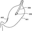
包括安装固定于这样的胶囊型医疗装置用留置装置200上的胶囊型内窥镜300的胶囊留置型医疗装置100,在留置固定于被检体400内的目标部位的状态下与接收装置等相组合,从而构成胶囊留置型医疗系统。图2是表示无线通信式胶囊留置型医疗系统的概略构成例的示意图。如图2所示,无线通信式胶囊留置型医疗系统包括胶囊留置型医疗装置100、便携型接收装置402、和便携型观测仪等显示装置403;上述胶囊留置型医疗装置100包括胶囊型内窥镜300,该胶囊型内窥镜300可被导入到被检体400内,而例如留置固定于胃401等体腔内的目标部位,拍摄胃401内的彩色图像,并利用无线通信向接收装置402发送影像信号等数据;上述接收装置402用于接收自胶囊型内窥镜300以无线通信方式发送来的彩色图像数据;上述显示装置403用于基于接收装置402接收到的影像信号显示彩色图像。接收装置402具有接收用天线404,该接收用天线404可粘贴于被检体400的体外表面上的、与胶囊型内窥镜300的留置固定部位相对应的部位,例如胃401附近。The indwelling capsule
由此,在使用消化管用的通用胶囊型内窥镜300的同时,将该胶囊型内窥镜300作为胶囊留置型医疗装置100留置固定于体腔内的目标部位,由胶囊型内窥镜300拍摄目标部位,通过显示装置403观察拍摄出的体腔内图像,从而适当地对手术后的患部进行监视等。 Thus, while using the general-
在此,参照图3~图4,依次说明包括将胶囊型内窥镜300留置于体腔内的作业的医疗操作程序。将胶囊型内窥镜300导入并留置于体腔内是为了监视在利用内窥镜进行手术之后患部是否出血等,是在利用内窥镜对作为对象的被检体400进行手术之后进行的。另外,也可以在利用内窥镜进行手术之前将胶囊型内窥镜300导入并留置于体腔内,而不在利用内窥镜进行手术之后进行留置作业。在图4等中,附图标记405表示利用内窥镜进行手术的手术部位(例如,黏膜切除部)。另外,在将胶囊型内窥镜300导入到体腔内前后的适当时机,将接收用天线404粘贴于被检体400的体外表面。 Here, with reference to FIGS. 3 to 4 , the medical operation procedure including the operation of placing the
首先,如图3所示,准备消化管用的通用胶囊型内窥镜300,通过将该胶囊型内窥镜300嵌合安装于保持部200内,使其与保持部202一体化。然后,将连结于保持部202的夹具203组装于使其自内窥镜406的钳子通道407突出的作为内窥镜处理器具的夹持处理器具1408上。然后,通过将夹具203和夹持处理器具1408拉入到钳子通道407内,从而将胶囊型内窥镜300与保持部202一同临时固定于内窥镜406的前端部分。 First, as shown in FIG. 3 , a general-
接着,如图4-1所示,在胶囊型内窥镜300及保持部202为一体的状态下,使内窥镜406通过被检体400的口腔导入到体腔内。在被导入至目标部位、例如胃401内之后,再次使夹持处理器具1408突出,使被保持部202保持着的胶囊型内窥镜300离开内窥镜406的前端。 Next, as shown in FIG. 4-1 , with the
然后,如图4-2所示,一边通过接收装置402、显示装置403监视由胶囊型内窥镜300拍摄的图像,从而确认作为监视对象的手术部位405是否位于胶囊型内窥镜300的光学观察系统307的观察视野内,一边利用夹持处理器具1408将夹具203卡定固定于体腔内组织上。此时,在本实施方式1中,准备2个夹具203,在将一个夹具203卡定于体腔内之后,用显示装置403监视由胶囊型内窥镜300拍摄的图像,调整剩余的夹具203的卡定部位,从而可以调整胶囊型内窥镜300的留置姿态。 Then, as shown in FIG. 4-2 , while monitoring the image captured by the
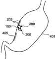
之后,自体腔内拔出内窥镜406,从而,如图4-3所示,胶囊型内窥镜300成为利用安装保持它的保持部202及夹具203而留置固定于体腔内的目标部位的状态,可以使用胶囊型内窥镜300进行留置观察。 Afterwards, the
监视结束之后,通过使卡定有夹具203的部分的体腔内组织坏死,使夹具203与保持部202、胶囊型内窥镜300一同脱落至体腔内,因此,可以通过回收网等,利用内窥镜在脱落的胶囊型内窥镜300与保持部202一体的状态下回收它们,也可以直接将它们排出到体腔外。 After the monitoring is completed, the
另外,在本实施方式中,以由口腔导入并留至胶囊型内窥镜300的例子进行了说明,但并不限定于从口腔导入胶囊型内窥镜300,例如,在自肛门、其他开口部导入并留置胶囊型内窥镜300的情况下也可以同样应用。 In addition, in this embodiment, an example of introducing the
变型例1
图5-1~图5-5例示了卡定部的变型例。图5-1表示这样的变型例:将通过突出形成保持部202的一部分而与保持部202形成为一体的孔部210作为卡定部,该孔部210通过使用内窥镜固定器具、例如内窥镜用止血夹具(未图示)而利用内窥镜处理器具固定于体腔内组织上。采用该变型例,构造简单,且制造容易。 5-1 to 5-5 illustrate modified examples of the locking portion. FIG. 5-1 shows a modified example in which a
图5-2表示这样的变型例:将连结设置于保持部202的环状线构件222作为卡定部,该环状线构件222通过使用内窥镜固定器具、例如内窥镜用止血夹具220而利用把持钳子等内窥镜处理器具固定于体腔内组织221上。采用该变型例,环状线构件222仅以环状连结即可,构造简单,且制造容易。 FIG. 5-2 shows a modified example in which an annular wire member 222 connected to the holding
在这种情况下,例如图5-3所示,若设置多个作为卡定部的环状线构件222a~222c,并使它们各自的尺寸不相同,则在以夹具220将它们卡定于体腔内组织221上时,可以根据目标部位附近的体腔内组织221的形状等选择最适合的环状线构件222a~222c,因此便于处理(approach),且提高了内窥镜处理的作业性。 In this case, for example, as shown in FIG. When on the
图5-4表示这样的变型例:将连结设置于保持部202的网状构件223作为卡定部,该网状构件223通过使用内窥镜固定器具、例如内窥镜用止血夹具220而利用把持钳子等内窥镜处理器具固定于体腔内组织221上。采用该变型例,可在任意位置将网状构件223卡定于体腔内组织221上,因此容易由夹具220进行卡定固定,且提高了内窥镜处理的作业性。另外,替代网状构件223,在使用布状构件、片状构件的情况下也可以得到同样的效果。 5-4 show a modified example in which a
图5-5表示这样的变型例:将吸引部231作为卡定部,该吸引部231通过突出形成保持部202的一部分而与保持部202形 成为一体,用于吸引要利用内窥镜固定器具、例如针230固定的体腔内组织221一部分。 5-5 show such a modified example: the
实施方式2Embodiment 2
参照图6及图7说明本发明的实施方式2。图6是表示本实施方式2的胶囊留置型医疗装置的构成例的剖视构造图。本实施方式2的胶囊型医疗装置用留置装置200,具有例如与胶囊型内窥镜300大致相同半径、且形成为两端开放的大致圆筒状的保持部240。该保持部240的前端罩壳体304a侧的前端侧突出形成为对胶囊型内窥镜300内置的光学观察系统307进行遮挡的遮挡部241。遮挡部241的突出量设定为不进入光学观察系统307的观察视野内,即位于观察视野外。另外,作为卡定部,可采用上述各种构成例,但在此为使用例如与图1的情况相同的夹具203的构成例。 Embodiment 2 of the present invention will be described with reference to FIGS. 6 and 7 . FIG. 6 is a cross-sectional structure diagram showing a configuration example of a capsule indwelling medical device according to Embodiment 2. FIG. The
胶囊型内窥镜300利用光学观察系统307,透过透明的前端罩壳体304a部分来拍摄体腔内图像,在作为观察窗的前端罩壳体304a部分发生污染等时,无法得到适当的图像。在以进行手术后的患部监视等为目的的留置观察的情况下,通常认为,在观察期间不会摄取食物,因此一般不会由进食等引起污染前端罩壳体304a的表面。但是,在体腔内进行蠕动运动,在长期的监视过程中有体液等液体附着在前端罩壳体304a表面上的可能性。在此,在本实施方式2中,由于保持部240具有遮挡部241,因此,可以防止在将胶囊型内窥镜300留置于体腔内的状态下污染前端罩壳体304a的表面,并且,即使保持部240为不透明构件,也不会妨碍光学观察系统307的观察视野,可由光学观察系统307良好地进行留置观察。 The
特别是,如图7所示,在为了在胃401内等中进行重力方向朝下的观察而留置了胶囊型内窥镜300的情况下,由于与胶囊 型内窥镜300一体地保持该胶囊型内窥镜300的保持部240在其前端(下端)侧具有遮挡部241,因此,作为观察窗的前端罩壳体304a的表面上难以附着体液等,可以防止其污染。 In particular, as shown in FIG. 7 , when the
变型例2Modification 2
图8是表示变型例2的胶囊留置型医疗装置的构成例的剖视构造图。变型例2的遮挡部241具有胶囊型内窥镜300用抵接部242,该抵接部242以使其前端侧内周部分与胶囊型内窥镜300的前端罩壳体304a外表面形状相吻合的方式,沿半径方向突出。即,由于抵接部242的内径小于胶囊型内窥镜300的外径,因此,在将胶囊型内窥镜300自图8中箭头所示的方向嵌合安装于保持部240中时,胶囊型内窥镜300停止于与遮挡部241的抵接部242抵接的位置。因此,不需要进行保持部240与胶囊型内窥镜300的对位,就可以简单地完成嵌合安装作业等。 8 is a cross-sectional structural view showing a configuration example of a capsule indwelling medical device according to Modification 2. FIG. The shielding
变型例3Modification 3
图9是表示变型例3的胶囊留置型医疗装置的构成例的剖视构造图。变型例3的保持部250具有由透明材料形成的遮挡部251。保持部250可以是整体由透明构件构成,也可以仅遮挡部251部分由透明构件构成。这样的遮挡部251突出形成至进入光学观察系统307的观察视野内的位置。更具体地说,形成为比胶囊型内窥镜300的前端罩壳体304a前端部分更突出,且形成为其位于重力方向上方的一侧较长。 9 is a cross-sectional structural view showing a configuration example of a capsule indwelling medical device according to Modification 3. FIG. The holding
采用变型例3,由于遮挡部251足够长,且覆盖了前端罩壳体304a表面的大部分,因此体液等难以附着在前端罩壳体304a表面,可以提高防污效果。在这种情况下,虽然是通过使遮挡部251进入观察视野内而确保遮挡部251的长度,但由于遮挡部251由透明构件形成,因此可以确保光学观察系统307的观察能力。 According to Modification 3, since the shielding
变型例4Variation 4
图10是表示变型例4的胶囊留置型医疗装置的构成例的剖视构造图。变型例4的保持部260具有由透明构件形成的、遮挡光学观察系统307的整个观察视野的、圆顶状遮挡部261。保持部260可以是整体由透明构件构成,也可以仅遮挡部261部分由透明构件构成。另外,保持部260形成有相当于抵接部242的抵接部262,该抵接部262位于保持部260与遮挡部261的分界部分。并且,在遮挡部261的外表面上实施防污涂敷而形成有防污涂敷膜263。该防污涂敷为防水涂敷、使用光催化剂材料等的亲水涂敷,其可根据用途(留置目的、部位等)分别使用。 10 is a cross-sectional structural view showing a configuration example of a capsule indwelling medical device according to Modification 4. FIG. The holding
采用变型例4,由于遮挡部261遮盖了整个观察视野(前端罩壳体304a的前方前表面),因此胶囊型内窥镜300的前端罩壳体304a表面不会被污染。而且,在遮挡部261的外表面形成有通过防污涂敷形成的防污涂敷膜263,因此遮挡部261自身也难以被污染,减少了对光学观察系统307的不良影响。特别是,若将遮挡部261的表面位置设定于胶囊型内窥镜300的光学观察系统307的焦深之外,则即使遮挡部261的外表面产生些许污染,由于光学观察系统307的焦点也未与污染处相对准,因此可以极力减小对观察的影响。 According to Modification 4, since the shielding
另外,虽然也可以对胶囊型内窥镜300的前端罩壳体304a外表面实施防污涂敷,但必须根据作为应用对象的部位的不同来选择进行防水涂敷还是进行亲水涂敷,损失了胶囊型内窥镜300自身的通用性。另一方面,若对遮挡部261的外表面实施防污涂敷,则即使胶囊型内窥镜300自身使用通用的构件,也可以根据用途来选择进行防水涂敷还是进行亲水涂敷,增大了材料的选择范围。 In addition, although it is also possible to apply antifouling coating to the outer surface of the front
变型例5Modification 5
图11是表示变型例5的胶囊留置型医疗装置的构成例的剖视构造图。变型例5的保持部260在变型例4的构成的基础上具有对光学观察系统307发挥功能的有光学特性的圆顶状遮挡部264。在变型例5中,通过适当调整遮挡部264原料的作为光学特性的折射率分布、曲率,可改变光学观察系统307所拍摄的图像的视场角、深度(depth)。在图例示子中,遮挡部264具有通过调整视场角来扩大观察视野角这样的光学特性。采用变型例5,可以与胶囊型内窥镜300的留置目的相应地得到光学性能,可以更加良好地进行监视观察。 11 is a cross-sectional structural view showing a configuration example of a capsule indwelling medical device according to Modification 5. FIG. The holding
实施方式3Embodiment 3
参照图12说明本发明的实施方式3。图12是表示本实施方式3的胶囊留置型医疗装置的构成例的剖视构造图。本实施方式3的胶囊型医疗装置用留置装置200的结构为:与保持部270一体的卡定部、例如孔部210位于胶囊型内窥镜300的前端罩壳体304a侧地形成,并且,该孔部210进入光学观察系统307的观察视野内。 Embodiment 3 of the present invention will be described with reference to FIG. 12 . FIG. 12 is a cross-sectional structural view showing a configuration example of a capsule indwelling medical device according to Embodiment 3. FIG. The
采用本实施方式3,由于孔部210也进入观察视野内,因此,在对孔部210进行夹持等卡定固定作业时,通过观看显示装置403的画面还可以确认孔部210的卡定固定状态,可以可靠地进行卡定固定。另外,即使在留置固定胶囊型内窥镜300之后进行监视时,不只是可以监视作为对象的手术部位,还可以同时监视孔部210的状态,可以及时发现发生脱落等。 According to Embodiment 3, since the
变型例6Modification 6
图13是表示变型例6的胶囊留置型医疗装置100的概略构成例的立体图。变型例6是在实施方式3的构成中的保持部270的基础上还在胶囊型内窥镜300的后部侧(观察视野后方)设有与孔部210位于同一侧(同一母线上)的作为卡定部的孔部 210a。另外,为了易于将孔部210、210a导入到体腔内,它们附近均由具有柔软性的构件构成。 FIG. 13 is a perspective view showing a schematic configuration example of a capsule indwelling
采用变型例6,由长度方向上的2处孔部210、210a将安装保持着胶囊型内窥镜300的保持部270卡定固定于体腔内组织上,因此, 固定状态可靠,可以可靠地固定胶囊型内窥镜300的视野。特别是,若在先将孔部210a侧卡定之后,一边用显示装置403监视由胶囊型内窥镜300拍摄图像、一边进行卡定孔部210侧的卡定作业,则可以可靠地固定胶囊型内窥镜300相对于目标部位的视野。 According to the modified example 6, the holding
在这种情况下,如图14所示,也可以设置相对于保持部270的胶囊型内窥镜300的前端罩壳体304a侧部分不同体的可后安装的可自由装卸于该前端罩壳体304a侧部分的、透明的遮挡部271。由此,可以根据使用用途、部位等通过装卸遮挡部271进行应对。 In this case, as shown in FIG. 14 , it is also possible to provide a rear-mounted, freely attachable and detachable part of the front-
实施方式4Embodiment 4
对本发明的实施方式4进行说明。图15是表示本实施方式4的胶囊留置型医疗装置的构成例的概略立体图,图16是表示胶囊留置型医疗装置的构成例的剖视构造图。该胶囊留置型医疗装置600包括胶囊型医疗装置用留置装置500、和安装保持于该胶囊型医疗装置用留置装置500中的作为胶囊型医疗装置的胶囊型内窥镜300。胶囊型内窥镜300的结构,例如图16所示,如以上实施方式1中所述。 Embodiment 4 of the present invention will be described. FIG. 15 is a schematic perspective view showing a configuration example of a capsule indwelling medical device according to Embodiment 4, and FIG. 16 is a cross-sectional structural view showing a configuration example of a capsule indwelling medical device. The indwelling capsule
另一方面,胶囊型医疗装置用留置装置500包括保持构件501和卡定构件502;上述保持构件501用于安装保持胶囊型内窥镜300;上述卡定构件502连结设置于该保持构件501,用于将胶囊型内窥镜300卡定固定于目标部位的体腔内组织上。 On the other hand, the
在此,保持构件501具有以与胶囊型内窥镜300的外周面面 接触状态一体地保持于胶囊型内窥镜300的外周面上的构造,一体地保持被嵌合安装的胶囊型内窥镜300。更具体地说,保持构件501形成为包含与胶囊型内窥镜300大致相同半径的大致圆筒状部分的形状,并形成为除了胶囊型内窥镜300的前端罩壳体304a一侧部分之外覆盖整个胶囊型内窥镜300的罩状。另外,保持构件501在其端部具有可由后述把持钳子把持的突出状把持部501a。 Here, the holding
另外,由保持构件501对胶囊型内窥镜300进行的安装保持可以是压入的方式、使用热收缩管等一旦安装之后就通过加热使之收缩而可靠地进行保持的方式、使用粘接剂等进行固定保持的方式等。要点在于采用如下这样的方式、构造即可:可安装现有的胶囊型内窥镜300,可以在体腔内进行监视的期间一直维持无法容易地拔出已安装的胶囊型内窥镜300的保持状态,且可以确保与胶囊型内窥镜300同等的吞入性(体腔内导入性)。另外,就材料而言,保持构件501为不损害胶囊型内窥镜300的观察功能、发送信息功能等,且即使导入、留置于体腔内也不会损害生物体的材料即可,采用硬质构件、软质构件(弹性构件)均可,另外,采用透明构件、不透明构件均可。 In addition, the mounting and holding of the
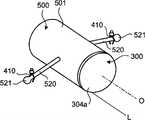
另外,卡定构件502在包含观察轴线O的平面上以观察轴线O为中心对称地突出为别针形(在观察轴线方向上的相分离位置具有与保持构件501连结的连结部的大致U字形),一体地形成于罩状的保持构件501的两侧,因此其前端部分成为卡定部503。即,两侧的一对卡定构件502具有卡定部503a、503b这2个卡定部,卡定部503a、503b在胶囊型内窥镜相对于体腔内组织的投影面之外的夹持胶囊型内窥镜300的位置、更具体地说是在夹着观察光学系统307的观察轴线O的方向上的位置,卡定于体腔内组织。 In addition, the locking
若改变观点,在将保持构件501(胶囊型内窥镜300)的最下位部的母线L部分作为用于设置于体腔内组织上的设置部504的情况下,本实施方式的卡定构件502由第1卡定构件502a和第2卡定构件502b构成;上述第1卡定构件502a具有第1卡定部503a,该第1卡定部503a设置于保持构件501(胶囊型内窥镜300)的朝上方向离开设置部504的位置,可通过后述内窥镜固定器具安装于体腔内组织上;上述第2卡定构件502b具有第2卡定部503b,该第2卡定部503b设置于保持构件501(胶囊型内窥镜300)的朝上方向离开设置部504的位置的、与第1卡定部503a位置不同的位置,可通过后述内窥镜固定器具安装于体腔内组织上。在此,所谓“最下位部”、“上方向”,在与体腔内组织的位置关系方面,是将保持构件501(胶囊型内窥镜300)的靠近体腔内组织的位置或方向作为最下位部或下方向,将离开体腔内组织的方向作为上方向,而不是指天地方向。另外,在不必特别区分2个卡定构件502a、502b以及卡定部503a、503b的情况下,适当地以卡定构件502、卡定部503来进行标记、说明。后述实施方式、变型例中的一对卡定构件、卡定部也同样,但为了便于说明,省略了以附记a、b的区别。 To change the point of view, when the generatrix L part of the lowest part of the holding member 501 (capsule endoscope 300) is used as the
这些卡定部503a、503b可利用内窥镜固定器具、在本实施方式4中为内窥镜用止血夹具410卡定于体腔内组织上。另外,卡定构件502至少由弹性材料构成,在被导入到体腔内时可绕保持构件501(因而是绕胶囊型内窥镜300)自由折叠,且可在因体腔内目标位置处的展开而恢复至原来固有的别针形状。与卡定构件502对胶囊型内窥镜300的附加限定的情况不同,卡定构件502对不含内置物的保持构件501的附加限定较少,可以简单地实现。另外,卡定构件502不一定必须与保持构件501为一体,也可以不同体,要点在于只要是可连结为一体即可。 These locking
包括安装固定于这样的胶囊型医疗装置用留置装置500上的胶囊型内窥镜300的胶囊留置型医疗装置600,在留置固定于被检体400内的目标部位的状态下与接收装置等相组合,从而构成胶囊留置型医疗系统。图17是表示无线通信式胶囊留置型医疗系统的概略构成例的示意图。如图17所示,无线通信式胶囊留置型医疗系统包括胶囊留置型医疗装置600、便携型接收装置402、和便携型观测仪等显示装置403;上述胶囊留置型医疗装置600包括胶囊型内窥镜300,该胶囊型内窥镜300可导入到被检体400内而留置固定于例如胃401等体腔内的目标部位,拍摄胃401内的彩色图像,利用无线通信向接收装置402发送影像信号等数据;上述便携型接收装置402接收自胶囊型内窥镜300以无线通信方式发送来的彩色图像数据;上述显示装置403基于接收装置402接收到的影像信号显示彩色图像。接收装置402具有接收用电线404,该接收用天线404可粘贴于被检体400的体外表面上的、与胶囊型内窥镜300的留置固定部位相对应的部位、例如胃401附近。 The indwelling capsule
由此,在使用消化管用的通用胶囊型内窥镜300的同时,将该胶囊型内窥镜300作为胶囊留置型医疗装置600留置固定于体腔内的目标部位,由胶囊型内窥镜300拍摄并观察目标部位,通过显示装置403观察拍摄出的体腔内图像,从而适当地对手术后的患部进行监视等。 Thus, while using the general-
在此,参照图18~图20,依次说明将胶囊型内窥镜300留置于体腔内的作业程序。将胶囊型内窥镜300导入并留置于体腔内是为了监视在利用内窥镜进行手术之后患部是否出血等,是在利用内窥镜对作为对象的被检体400进行手术之后进行的。另外,也可以在利用内窥镜进行手术之前,将胶囊型内窥镜300导入并留置于体腔内,而不在利用内窥镜进行手术之后 进行留置作业。另外,在将胶囊型内窥镜300导入到体腔内前后的适当时机,将接收用天线404粘贴于被检体400的体外表面上。 Here, referring to FIGS. 18 to 20 , the operation procedure for placing the
首先,准备消化管用的通用胶囊型内窥镜300,通过将该胶囊型内窥镜300嵌合安装于保持构件501内,使其与保持构件501一体化。然后,如图18所示,用通入到内窥镜406的钳子通道407内的把持钳子408把持保持构件501端部的把持部501a,将胶囊留置型医疗装置600拉入到内窥镜406前端的筒状输送构件409内。此时,绕保持构件501周围卷绕地弯曲折叠卡定构件502,将其拉入到输送构件409内,从而不会在输送构件409的周围产生多余的突出部分。 First, a general-
然后,如图19-1所示,在将胶囊留置型医疗装置600拉入到输送构件409内的状态下,将内窥镜406的前端侧导入到体腔内。此时,由于卡定构件502等未处于伸出状态,因此不会妨碍内窥镜300导入到体腔内,而可以与胶囊型内窥镜300单体的情况同样地被导入到体腔内。 Then, as shown in FIG. 19-1 , with the indwelling capsule
在将内窥镜406的前端侧导入至体腔内的目标部位、例如胃401等处的手术后监视部位附近时,如图19-2所示,打开把持钳子408而将胶囊留置型医疗装置600自输送构件409内放到体腔内。随着在该体腔内进行的打开操作,在胶囊留置型医疗装置600中折叠的卡定构件502利用弹性复原力恢复展开为原来固有的形状、即别针形状。 When the front end side of the
因此,如图19-2及图20所示所示,本次使用把持钳子408等内窥镜处理器具对被放入到体腔内的胶囊留置型医疗装置600进行内窥镜处理,由此,利用2个内窥镜固定器具、在此为内窥镜用止血夹具410将卡定构件502前端的2处卡定部503a、503b卡定固定于体腔内组织411上。此时,向外方拉卡定构件 502以使其处于相对于保持构件501具有拉力的状态,利用内窥镜用止血夹具410将卡定部503a、503b卡定固定于体腔内组织411上。 Therefore, as shown in FIG. 19-2 and FIG. 20 , endoscopic treatment is performed on the capsule indwelling
此时,一边通过接收装置402、显示装置403监视由胶囊型内窥镜300拍摄的图像,从而确认作为监视对象的手术部位是否位于胶囊型内窥镜300的光学观察系统307的观察视野内,而确定留置方向,一边通过把持钳子408等操作内窥镜用止血夹具410,而将卡定部503a、503b卡定固定于体腔内组织411上。此时,在本实施方式4中,准备2个卡定部503a、503b,在通过内窥镜用止血夹具410将其中的一个卡定部卡定于体腔内之后,通过显示装置403监视由胶囊型内窥镜300拍摄的图像,通过内窥镜用止血夹具410调整剩余的卡定部503b(或者503a)的卡定位置,从而可以调整胶囊型内窥镜300的留置姿态。 At this time, while monitoring the image captured by the
之后,如图20所示,自体腔内拔出内窥镜406,从而使胶囊型内窥镜300成为通过安装保持它的保持构件501及卡定构件502而留置固定于体腔内的目标部位的状态,可以使用胶囊型内窥镜300进行留置观察。 After that, as shown in FIG. 20 , the
监视结束之后,通过使卡定有内窥镜用止血夹具410的部分的体腔内组织411坏死,使内窥镜用止血夹具410与保持构件501、胶囊型内窥镜300一同脱落至体腔内,因此,可以在脱落了的胶囊型内窥镜300与保持构件501一体的状态下利用回收网等而利用内窥镜回收它们,也可以在该状态下将它们排出到体腔外。 After the monitoring is completed, the
在此,参照图21及图22说明胶囊型内窥镜300(保持构件501)的留置固定状态。图21是表示留置固定状态的概略俯视图,图22是表示留置固定状态的概略剖视图。在本实施方式4中,卡定构件502设定于胶囊型内窥镜相对于体腔内组织411的 投影面之外的、沿与观察轴线O正交的方向夹着该胶囊型内窥镜300的位置,由于用内窥镜用止血夹具410使卡定构件502的2个卡定部503a、503b带有张力地卡定于该体腔内组织411上,因此,成为与观察轴线O平行的胶囊型内窥镜300的母线L在规定方向上与体腔内组织411稳定地线接触的留置固定状态,可以确保观察光学系统307观察视野的朝向或者观察轴线O没有偏差的留置状态。 Here, the indwelling and fixing state of the capsule endoscope 300 (holding member 501 ) will be described with reference to FIGS. 21 and 22 . FIG. 21 is a schematic plan view showing the indwelling and fixing state, and FIG. 22 is a schematic cross-sectional view showing the indwelling and fixing state. In Embodiment 4, the locking
即,在本实施方式4中,卡定构件502由第1卡定构件502a和第2卡定构件502b构成;第1卡定构件502a具有第1卡定部503a,该第1卡定部503a设置于保持构件501(胶囊型内窥镜300)的朝上方向离开设置部504的位置;上述第2卡定构件502b具有第2卡定部503b,该第2卡定部503b设置于朝上方向离开设置部504的、与第1卡定部503a位置不同的位置。使用卡定构件502,用内窥镜用止血夹具410使2个卡定部503a、503b带有张力地卡定于该体腔内组织411上,因此,成为与观察轴线O平行的保持构件501(胶囊型内窥镜300)的设置部504在预定方向上与体腔内组织411稳定地线接触的留置固定状态,可以确保观察光学系统307观察视野的朝向或者观察轴线O没有偏差的留置状态。 That is, in Embodiment 4, the locking
更详细地说,无论是如图21所示那样俯视,还是如图22沿观察轴线方向看,设定卡定部503a、503b的卡定位置、并在带有张力的状态下利用内窥镜用止血夹具410使卡定部503a、503b卡定于体腔内组织411上,使得以各个卡定部503a、503b的卡定位置为中心的箭头所示的作用于胶囊型内窥镜300的力矩互相抵消,因此,不会发生观察视野的朝向晃动这样的摆动,而可以继续以稳定的状态监视体腔内。 More specifically, regardless of whether it is viewed from above as shown in FIG. 21 or viewed along the viewing axis direction in FIG. The locking
变型例7Modification 7
参照图23-1及图23-2说明变型例7。图23-1是表示变型例7的构成例的概略立体图,图23-2是表示其回收除去时的样子的概略立体图。如图23-1所示,变型例7替代卡定构件502而使用俯视时为大致8字形或∝字形的卡定构件505,将卡定构件505的外侧前端部分作为卡定部506,并预先在分界部分设置易于切断的裂缝507。 Modification 7 will be described with reference to FIGS. 23-1 and 23-2 . FIG. 23-1 is a schematic perspective view showing a configuration example of Modification 7, and FIG. 23-2 is a schematic perspective view showing a state when it is collected and removed. As shown in Figure 23-1, instead of the locking
这样,如图23-2所示,在监视动作结束后,导入内窥镜406,用把持钳子408等把持并拉卡定构件505的内侧部分,而使卡定构件502在裂缝507部分切断,从而可以在放置由内窥镜用止血夹具410夹持的卡定部506部分的状态下进行回收胶囊型内窥镜300的作业。 In this way, as shown in FIG. 23-2, after the monitoring operation is completed, the
变型例8Modification 8
参照图24说明变型例8。图24是表示变型例8的构成例的概略立体图。变型例8替代单纯的别针形卡定构件502而使位于保持构件501两侧的卡定构件510叠加成多列的别针形状,从而形成为两侧分别具有排列成多个卡定部511a、511b、511c......的形状。采用这样的构成,内窥镜用止血夹具410进行的卡定于体腔内组织411上的作业,可以根据卡定部位的体腔内组织411的状况等从一侧的多个卡定部511a、511b、511c......中选择易于进行夹持的部位来进行,易于进行内窥镜处理的卡定作业。 Modification 8 will be described with reference to FIG. 24 . FIG. 24 is a schematic perspective view showing a configuration example of Modification 8. FIG. Modification 8 Instead of the simple pin-shaped
变型例9Modification 9
参照图25及图26说明变型例9。图25是表示变型例9的构成例的概略立体图,图26是表示其卡定状态的概略主视图。变型例9替代在包含观察轴线O的平面上设于保持构件501两侧的卡定构件502,而设有偏置于保持构件501(胶囊型内窥镜300)的一侧面侧、且与保持构件501相切地形成为一体的卡定构件515。即,卡定构件515呈在保持构件501两侧连续的平面形状。 Modification 9 will be described with reference to FIGS. 25 and 26 . FIG. 25 is a schematic perspective view showing a configuration example of Modification 9, and FIG. 26 is a schematic front view showing a locked state thereof. Modification 9 replaces the locking
采用这样的构成,在自图19-2中说明的输送构件409向体腔内放置胶囊留置型医疗装置600时,如图26所示,呈连续的平面形状的卡定构件515与体腔内组织411面接触,因此,与圆筒状的保持构件501直接接触于体腔内组织411的情况相比,不会产生翻滚而易于保持稳定的状态,因此,由内窥镜用止血夹具410卡定卡定部503的作业也变得容易且可靠。 With such a configuration, when the capsule indwelling
另外,对于图25所示的构成,如图27所示,也可以将保持构件501与卡定构件515的连结部配设在与要卡定的体腔内组织411相反一侧的位置,用内窥镜用止血夹具410使其卡定部503卡定于体腔内组织411上。这样,如图27中的箭头A所示,由带有张力地被卡定的卡定构件515,施加向体腔内组织411侧推压胶囊型内窥镜300的较强的力,可以更加可靠地得到母线L在所期望方向上与体腔内组织411线接触的状态。 In addition, for the configuration shown in FIG. 25 , as shown in FIG. 27 , the connecting portion of the holding
变型例10Modification 10
参照图28说明变型例10。图28是表示变型例10的构成例的概略立体图。变型例10替代别针状的卡定构件502,而设有与保持构件501一体的、在前端具有大直径的卡定部521的、棒状卡定构件520。沿与观察轴线O正交的方向形成卡定构件520,卡定部521配设于夹着观察轴线O的位置。与卡定构件502的情况相同,该卡定构件520也由弹性材料构成,并且,在保持构件501导入到体腔内时可绕保持构件501(胶囊型内窥镜300)自由折叠,且在体腔内展开时会恢复展开为原来固有的形状、即棒状。该卡定构件520虽然是在包含观察轴线O的平面上与保持构件501形成为一体,但也可以与在图25等中说明的情况相同,偏置于保持构件501的一侧面侧并与之相切地连结。 Modification 10 will be described with reference to FIG. 28 . FIG. 28 is a schematic perspective view showing a configuration example of Modification 10. FIG. In Modification 10, instead of the pin-shaped
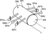
采用变型例10的构成,也可以得到与上述情况相同的效果。另外,棒状的卡定构件520并不限定为一侧设至一根,例 如图29所示,也可以在每一侧各设置多个卡定构件520a~520c,这些卡定构件520a~520c分别具有卡定部521a~521c。这样,与图24所示的情况相同,由内窥镜用止血夹具410进行的卡定于体腔内组织411上的作业,可以根据卡定部位的体腔内组织411的状况等,从一侧的多个卡定部521a~521c中选择易于进行夹持的部位,易于通过内窥镜处理进行卡定作业。 Also with the configuration of Modification 10, the same effects as those described above can be obtained. In addition, the rod-shaped
变型例11Modification 11
参照图30及图31说明变型例11。图30是表示变型例11的构成例的概略立体图,图31是表示网状构件的折叠状态的概略立体图。变型例11替代在特定部位具有卡定部503、521的卡定构件502、520等,而沿与观察轴线O正交的方向在保持构件501上设有卡定构件525,该卡定构件525由在任意部位具有卡定部526的网状构件构成,在连结部527处利用粘接剂等连结于保持构件501上。卡定构件525的宽度与保持构件501的长度相当,连结部527沿保持构件501的外周面上的轴向设定在卡定构件525的整个宽度范围内。如图31所示,该卡定构件525由弹性材料构成,可绕保持构件501卷绕并自由折叠,且在展开状态下可恢复展开为原来的网状展开形状。 Modification 11 will be described with reference to FIGS. 30 and 31 . FIG. 30 is a schematic perspective view showing a configuration example of Modification 11, and FIG. 31 is a schematic perspective view showing a folded state of a mesh member. Modification 11, instead of locking
对于这样的结构,在卡定构件525为图31所示那样的折叠状态下,将胶囊型内窥镜300导入到体腔内,并自输送装置409被放入到体腔内,从而成为放开状态时,卡定构件525恢复展开为原来的网状展开形状。因此,例如,如图30所示,使卡定构件525处于成为保持构件501(胶囊型内窥镜300)的上部侧的配设状态,且将观察光学系统307的观察视野调整为所期望的朝向,并且,在卡定构件525对保持构件501带有拉力的状态下,用内窥镜用止血夹具410使卡定部526卡定于体腔内组织411上。此时,卡定构件525由网状构件构成,可以将内窥镜用 止血夹具410卡定于任意位置,即,卡定部526的位置为任意,因此,可以选择易于进行卡定的部位来进行卡定,提高了卡定作业效率。另外,即使在保持构件501(胶囊型内窥镜300)的各侧中的任一侧进行卡定,也可任意在多个部位进行卡定。 With such a configuration, the
即使是由这种网状构件构成的卡定构件525进行的卡定,也是在胶囊型内窥镜相对于体腔内组织411的投影面之外的、夹着胶囊型内窥镜300的位置,使卡定构件525带有张力地卡定于体腔内组织411上,从而固定了连结部527的方向性,因此,可以使保持构件501(胶囊型内窥镜300)的母线L在所期望方向上与体腔内组织411线接触,且观察视野的朝向或者观察轴线O不会偏地使卡定构件525卡定在体腔内组织411上。特别是如图30所示,若将连结部527配设于与体腔内组织411相反一侧的位置地使卡定构件525进行卡定,则与图27的情况相同,也可以对胶囊型内窥镜300作用朝向体腔内组织411侧的推压力,成为稳定的卡定状态。另外,与图26的情况相同,也可以将连结部527配设于体腔内组织411侧的位置地卡定卡定构件525。 Even the locking by the locking
另外,替代由网状构件构成卡定构件525,如图32所示,即使使用由纤维材质的片状构件构成的卡定构件530,也可以得到同样的效果。附图标记531是通过插入并卡定内窥镜用止血夹具410而在开孔的部位特定的任意的卡定部。另外,卡定构件530和保持构件501通过与连结部527的情况相同的连结部(未图示)连结为一体。 In addition, instead of forming the locking
实施方式5Embodiment 5
参照图33~图34-2说明本发明的实施方式5。图33是表示本发明实施方式5的构成例的概略立体图,图34-1是表示单侧卡定状态的样子的概略立体图,图34-2是表示两侧卡定状态的样子的概略立体图。在本实施方式5中,在两端分别具有卡 定部535且形成为细长状的卡定构件536,通过转动支点537连结于保持构件501的外周面上,从而,卡定构件536与保持构件501以可相互转动的状态设置。另外,卡定构件536由弹性材料构成,并且,在被导入到体腔内时,可绕保持构件501(因而是绕胶囊型内窥镜300)弯曲而自由折叠,且因在体腔内的目标位置放开而恢复展开为原来固有的形状。 Embodiment 5 of the present invention will be described with reference to FIGS. 33 to 34-2. 33 is a schematic perspective view showing a configuration example according to Embodiment 5 of the present invention, FIG. 34-1 is a schematic perspective view showing a one-side locked state, and FIG. 34-2 is a schematic perspective view showing a double-side locked state. In Embodiment 5, the elongated locking
对于这样的结构,在将胶囊留置型医疗装置600导入到体腔内的目标位置并将其放开之后,在将卡定构件536配设成使转动支点537位于与体腔内组织411相反的一侧的状态下,大致确定胶囊型内窥镜300的留置位置及视野方向,如图34-1所示那样由内窥镜用止血夹具410使一侧的卡定部535卡定于体腔内组织411上。在该状态下,一边监视显示装置403,一边如图34-1中的假想线所示那样微调胶囊型内窥镜300的留置位置及视野方向。然后,如图34-2所示,在成为目标留置位置及视野方向的状态下,向外方牵拉卡定构件536的剩余的卡定部535侧,使其牵拉保持构件501,而由内窥镜用止血夹具410将该卡定部535卡定于体腔内组织411上。由此,成为也作用有由卡定构件536向体腔内组织411侧推压保持构件501(胶囊型内窥镜300)的力的卡定状态,保持构件501(胶囊型内窥镜300)不会相对于卡定构件536转动,而可以维持在使母线L在所期望的方向上与体腔内组织411线接触的状态,可以得到正确的视野。 With such a structure, after the indwelling capsule
另外,若做成保持构件501与卡定构件536之间的转动需要由内窥镜处理器具施加外力的结构,则也可以配设卡定构件536并使其卡定,并使转动支点537处于体腔内组织411一侧。 In addition, if the rotation between the holding
变型例12
参照图35说明变型例12。图35是表示变型例12的构成例的 概略立体图。变型例12替代卡定构件536而具有卡定构件543、544这2个卡定构件,这2个卡定构件543、544分别在端部具有卡定部541、542,一个卡定构件543通过转动支点545可转动地连结于保持构件501的外周面上,另一个卡定构件544朝保持构件501的与卡定构件543相反的一侧延伸设置,并固定连结于保持构件501的外周面上。特别是,卡定构件544的与保持构件501连结的部分为两岔状,具有沿保持构件501的长度方向分离开的两处连结部。另外,卡定构件543、544均由弹性材料构成,并且,在被导入到体腔内时,可绕保持构件501(因而是绕胶囊型内窥镜300)弯曲而自由折叠,且因被在体腔内的目标位置展开而恢复展开为原来固有的形状。
在这样的构造中,在将胶囊留置型医疗装置600导入到体腔内的目标位置并将其放开之后,在将卡定构件543、544配设成使转动支点545、连结部位于与体腔内组织411相反的一侧的状态下,大致确定胶囊型内窥镜300的留置位置及视野方向,首先,用内窥镜用止血夹具410使可动侧的卡定部535卡定于体腔内组织411上。在该状态下,由于保持构件501可相对于卡定构件543转动,因此,一边监视显示装置403,一边微调胶囊型内窥镜300的留置位置及视野方向。然后,在胶囊型内窥镜300成为所期望的留置位置及视野方向的状态下,向外方牵拉固定侧的卡定构件544的卡定部542侧,使其相对于对保持构件501带有拉力,由内窥镜用止血夹具410将该卡定部542卡定于体腔内组织411上。由此,使保持构件501不会相对于卡定构件544移动,且成为也作用由卡定构件543、544向体腔内组织411侧推压保持构件501(胶囊型内窥镜300)的力的卡定状态,保持构件501(胶囊型内窥镜300)不会相对于卡定构件543、544转动,而可以维持在母线L在所期望的方向上与体腔内组织411 线接触的状态,可以得到正确的视野。 In such a configuration, after the indwelling capsule
变型例13Modification 13
参照图36说明变型例13。图36是表示变型例13的构成例的概略立体图。变型例13中的在两端分别具有卡定部550、551、且形成为细长状的卡定构件552,利用转动支点553连结于保持构件501的外周面上,从而,卡定构件552与保持构件501以可相互转动的状态设置。在此,为了使卡定构件552与保持构件501之间相互转动,将卡定构件552与保持构件501做成半固定的连结构造,从而需要使用内窥镜、钳子等内窥镜处理器具的强制外力才能转动,而不会因重力等转动。 Modification 13 will be described with reference to FIG. 36 . FIG. 36 is a schematic perspective view showing a configuration example of Modification 13. FIG. In Modification 13, the locking
并且,与上述各实施方式、变型例等的情况相同,卡定部550、551中的一个卡定部550构成可通过内窥镜用止血夹具410卡定于体腔内组织411上的部分,而另一个卡定部551构成自身具有卡定于体腔内组织411上的功能、并可通过内窥镜处理直接卡定处理于体腔内组织上的卡定部分。在变型例13中,卡定部551形成为朝向外方的钉子状并设有2个,但卡定部551也可以是锚构造。 In addition, as in the above-mentioned embodiments, modifications, etc., one of the locking
另外,卡定构件552由弹性材料构成,并且,在被导入到体腔内时,可绕保持构件501(因而是绕胶囊型内窥镜300)弯曲而自由折叠,且因在体腔内的目标位置展开而恢复展开为原来固有的形状。 In addition, the locking
在这样的结构中,在将胶囊留置型医疗装置600导入到体腔内的目标位置并将其放开之后,在将卡定构件552配设成使转动支点553位于体腔内组织411侧的状态下,大致确定胶囊型内窥镜300的留置位置及视野方向,首先,由内窥镜用止血夹具410将卡定部550卡定于体腔内组织411上。在该状态下,一边监视显示装置403,一边通过使用内窥镜处理器具施加强制 的外力而微调胶囊型内窥镜300的留置位置及视野方向。然后,在成为所期望的留置位置及视野方向的状态下,向外方牵拉钉子状的卡定部551侧,使其相对于对保持构件501带有拉力,而通过由内窥镜处理器具将该卡定部551插入到体腔内组织411中,从而直接将其卡定。在这样的状态下,成为只要不施加强制的外力,保持构件501就不会相对于卡定构件552移动的卡定状态,保持构件501(胶囊型内窥镜300)不会相对于卡定构件552转动,而可以维持在母线L在所期望的方向上与体腔内组织411线接触的状态,可以得到正确的视野。另外,夹持处理也仅在卡定部550侧这一处进行即可,较为简单。 In such a configuration, after the indwelling capsule
变型例14Modification 14
参照图37说明变型例14。图37是表示变型例14的构成例的概略立体图。变型例14利用连结部557(也可以是转动支点)使在两端具有卡定部555的带状卡定构件556连结设置于保持构件501的外周面上,并在带状卡定构件556的一部分设有具有止回构造的束缚构件558。包括束缚构件558的卡定构件556由弹性材料构成,且可绕保持构件501卷绕地自由折叠,在这一点与上述情况相同。 Modification 14 will be described with reference to FIG. 37 . FIG. 37 is a schematic perspective view showing a configuration example of Modification 14. FIG. Modification 14 uses a connecting portion 557 (which may also be a fulcrum for rotation) to connect a strip-shaped
在这样的结构中,在将胶囊留置型医疗装置600导入到体腔内的目标位置并将其放开之后,在将卡定构件556配设成使连结部557位于与体腔内组织411相反的一侧的状态下,由内窥镜用止血夹具410使一侧的卡定部555卡定于体腔内组织411上。接着,由内窥镜用止血夹具410将另一个卡定部555也卡定于体腔内组织411上。在此,在卡定构件556松弛的情况下,使束缚构件558向收紧的方向移动,从而调整为卡定构件556牵拉保持构件501的状态。束缚构件558由于具有止回构造,因此在调整后不会沿带长度方向自由运动。由此,成为也作用有由卡 定构件556向体腔内组织411侧强力推压保持构件501(胶囊型内窥镜300)的力的卡定状态,保持构件501(胶囊型内窥镜300)可以维持在母线L在所期望的方向上与体腔内组织411线接触的状态,可以得到正确的视野。 In such a structure, after the indwelling capsule
实施方式6Embodiment 6
参照图38说明实施方式6。图38是表示本实施方式6的构成例的概略立体图。本实施方式6具有卡定构件561,并由连结构件562使保持构件501外周面的一部分可相对于卡定构件561移动地与之该卡定构件561连结,上述卡定构件561由形成为比胶囊型内窥镜300长的直线带状的引导构件构成,卡定构件561两端的卡定部560与欲留置胶囊型内窥镜300的方向一致地以拉伸设置状态被卡定在体腔内组织411上。在此,卡定构件561在整个长度上具有锯齿状的止回构造,连结构件562仅可朝一个方向移动地被连结卡定。 Embodiment 6 will be described with reference to FIG. 38 . FIG. 38 is a schematic perspective view showing a configuration example of the sixth embodiment. Embodiment 6 has a locking
采用本实施方式6的结构,使卡定构件561与欲留置胶囊型内窥镜300的方向一致地定位于体腔内组织411上,使其两端的卡定部560以张拉设置状态卡定于体腔内组织411上,从而也确定了用连结构件562连结于卡定构件561上的保持构件501(从而是胶囊型内窥镜300)的姿态。即,与观察轴线O平行的胶囊型内窥镜300的母线L,成为在所期望方向上通过连结构件562及卡定构件561间接但稳定地与体腔内组织411线接触的留置固定状态,可以确保观察光学系统307的观察视野的朝向或者观察轴线O没有偏差的留置状态。另外,由于连结构件562可相对于卡定构件561移动地与之连结,因此,即使在使卡定构件561卡定于体腔内组织411上之后,也可以在观察轴线方向调整胶囊型内窥镜300的位置,并将其固定。 With the structure of Embodiment 6, the locking
变型例15Modification 15
参照图39说明变型例15。图39是表示变型例15的构成例的概略立体图。变型例15虽然与实施方式6的情况同样地使用在沿观察轴线O的轴向夹着胶囊型内窥镜300的位置设有卡定位置的卡定构件,但在使用线状的卡定构件565这一点上不同。即,使在端部设有卡定部566的卡定构件565连结设置于胶囊型内窥镜300的前端罩壳体304a的前部和保持构件501的把持部501a,使胶囊型内窥镜300与欲留置其的方向一致地定位该卡定构件565上,由内窥镜用止血夹具410将端部的卡定部566卡定于体腔内组织411上,从而使卡定构件565也与该方向一致、且成为拉伸设置的状态。 Modification 15 will be described with reference to FIG. 39 . FIG. 39 is a schematic perspective view showing a configuration example of Modification 15. FIG. Modification 15 uses locking members provided with locking positions at positions sandwiching the
采用变型例15的结构,与欲留置胶囊型内窥镜300的方向一致地也确定卡定构件565的方向,将其端部的卡定部566以拉伸设置状态卡定于体腔内组织411上,从而也确定了连结有卡定构件565的保持构件501、胶囊型内窥镜300的姿态。即,使与观察轴线O平行的胶囊型内窥镜300的母线L,成为在所期望的方向上稳定地与体腔内组织411线接触的留置固定状态,可以确保观察光学系统307的观察视野的朝向或者观察轴线O没有偏差的留置状态。 With the structure of Modification 15, the direction of the locking
本发明并不限定于上述实施方式,只要在不脱离本发明主旨的范围内就可以进行各种变形。例如,在上述说明中,以具有安装保持胶囊型内窥镜300的保持构件501、并使卡定构件连结设置于该保持构件501上的例子进行了说明,但也可以省略保持构件501,通过使卡定构件直接连结设置于胶囊型内窥镜300,来构成胶囊留置型医疗装置。特别是,若在采用图30、图32等所示的卡定构件525、530的情况下,则不对胶囊型内窥镜300实施特别的处理而可以直接连结,较为合适。 The present invention is not limited to the above-described embodiments, and various modifications can be made without departing from the gist of the present invention. For example, in the above description, an example has been described in which the holding
工业实用性Industrial Applicability
如上所述,本发明的胶囊型医疗装置用留置装置、胶囊内窥镜用生物体内留置装置、及胶囊留置型医疗装置适用于通过胶囊型医疗装置监视体腔内,特别适合将小肠用胶囊内窥镜这样的通用消化管用胶囊内窥镜一并用于体腔内留置用。 As described above, the indwelling device for a capsule medical device, the indwelling device for a living body for a capsule endoscope, and the indwelling capsule medical device of the present invention are suitable for monitoring the inside of a body cavity with a capsule medical device, and are particularly suitable for monitoring the small intestine with a capsule endoscope. Capsule endoscopes for general-purpose digestive tracts such as endoscopes are used for indwelling in body cavities. the
Claims (59)
Applications Claiming Priority (5)
| Application Number | Priority Date | Filing Date | Title |
|---|---|---|---|
| JP2005200886AJP4734051B2 (en) | 2005-07-08 | 2005-07-08 | Capsule type medical device indwelling device and capsule endoscope in vivo indwelling device |
| JP200886/2005 | 2005-07-08 | ||
| JP2005209089AJP4800692B2 (en) | 2005-07-19 | 2005-07-19 | Capsule type medical device indwelling device |
| JP209089/2005 | 2005-07-19 | ||
| PCT/JP2006/313512WO2007007648A1 (en) | 2005-07-08 | 2006-07-06 | Apparatus for placing capsule type medical device, apparatus for placing capsule endoscope in the body and capsule type medical device for placement |
Publications (2)
| Publication Number | Publication Date |
|---|---|
| CN101217908A CN101217908A (en) | 2008-07-09 |
| CN101217908Btrue CN101217908B (en) | 2012-10-24 |
Family
ID=37637041
Family Applications (1)
| Application Number | Title | Priority Date | Filing Date |
|---|---|---|---|
| CN2006800249427AExpired - Fee RelatedCN101217908B (en) | 2005-07-08 | 2006-07-06 | Apparatus for placing capsule type medical device, apparatus for placing capsule endoscope in the body |
Country Status (4)
| Country | Link |
|---|---|
| US (1) | US20090018396A1 (en) |
| EP (1) | EP1902663A4 (en) |
| CN (1) | CN101217908B (en) |
| WO (1) | WO2007007648A1 (en) |
Families Citing this family (84)
| Publication number | Priority date | Publication date | Assignee | Title |
|---|---|---|---|---|
| KR101048916B1 (en) | 2004-09-08 | 2011-07-12 | 올림푸스 가부시키가이샤 | Capsule Type Medical Device |
| JP4593211B2 (en)* | 2004-09-08 | 2010-12-08 | オリンパス株式会社 | Capsule medical device |
| JP2008029527A (en)* | 2006-07-27 | 2008-02-14 | Olympus Medical Systems Corp | Endoscope system |
| US7655004B2 (en) | 2007-02-15 | 2010-02-02 | Ethicon Endo-Surgery, Inc. | Electroporation ablation apparatus, system, and method |
| US8075572B2 (en) | 2007-04-26 | 2011-12-13 | Ethicon Endo-Surgery, Inc. | Surgical suturing apparatus |
| US8100922B2 (en) | 2007-04-27 | 2012-01-24 | Ethicon Endo-Surgery, Inc. | Curved needle suturing tool |
| US9339174B2 (en)* | 2007-07-18 | 2016-05-17 | Given Imaging Ltd | Device and method for viewing a body lumen |
| WO2009037945A1 (en)* | 2007-08-28 | 2009-03-26 | National University Corporation Chiba University | Laparoscopic surgery assisting robot |
| US8568410B2 (en) | 2007-08-31 | 2013-10-29 | Ethicon Endo-Surgery, Inc. | Electrical ablation surgical instruments |
| JP5242101B2 (en)* | 2007-08-31 | 2013-07-24 | オリンパスメディカルシステムズ株式会社 | Capsule endoscope |
| US8579897B2 (en) | 2007-11-21 | 2013-11-12 | Ethicon Endo-Surgery, Inc. | Bipolar forceps |
| US8262655B2 (en) | 2007-11-21 | 2012-09-11 | Ethicon Endo-Surgery, Inc. | Bipolar forceps |
| JP5096090B2 (en)* | 2007-09-19 | 2012-12-12 | オリンパスメディカルシステムズ株式会社 | In-vivo image receiving apparatus and in-vivo image acquisition system |
| CN101808567B (en)* | 2007-09-26 | 2012-09-05 | 奥林巴斯医疗株式会社 | Introduction-into-subject system |
| US20090112059A1 (en) | 2007-10-31 | 2009-04-30 | Nobis Rudolph H | Apparatus and methods for closing a gastrotomy |
| US8480657B2 (en) | 2007-10-31 | 2013-07-09 | Ethicon Endo-Surgery, Inc. | Detachable distal overtube section and methods for forming a sealable opening in the wall of an organ |
| US8262680B2 (en) | 2008-03-10 | 2012-09-11 | Ethicon Endo-Surgery, Inc. | Anastomotic device |
| US8317806B2 (en) | 2008-05-30 | 2012-11-27 | Ethicon Endo-Surgery, Inc. | Endoscopic suturing tension controlling and indication devices |
| US8652150B2 (en) | 2008-05-30 | 2014-02-18 | Ethicon Endo-Surgery, Inc. | Multifunction surgical device |
| US8771260B2 (en) | 2008-05-30 | 2014-07-08 | Ethicon Endo-Surgery, Inc. | Actuating and articulating surgical device |
| US8114072B2 (en) | 2008-05-30 | 2012-02-14 | Ethicon Endo-Surgery, Inc. | Electrical ablation device |
| US8070759B2 (en) | 2008-05-30 | 2011-12-06 | Ethicon Endo-Surgery, Inc. | Surgical fastening device |
| US8679003B2 (en) | 2008-05-30 | 2014-03-25 | Ethicon Endo-Surgery, Inc. | Surgical device and endoscope including same |
| US8906035B2 (en) | 2008-06-04 | 2014-12-09 | Ethicon Endo-Surgery, Inc. | Endoscopic drop off bag |
| US8403926B2 (en) | 2008-06-05 | 2013-03-26 | Ethicon Endo-Surgery, Inc. | Manually articulating devices |
| JP2010012222A (en) | 2008-06-06 | 2010-01-21 | Olympus Medical Systems Corp | Medical apparatus |
| US8361112B2 (en) | 2008-06-27 | 2013-01-29 | Ethicon Endo-Surgery, Inc. | Surgical suture arrangement |
| US8888792B2 (en) | 2008-07-14 | 2014-11-18 | Ethicon Endo-Surgery, Inc. | Tissue apposition clip application devices and methods |
| US8262563B2 (en) | 2008-07-14 | 2012-09-11 | Ethicon Endo-Surgery, Inc. | Endoscopic translumenal articulatable steerable overtube |
| US8211125B2 (en) | 2008-08-15 | 2012-07-03 | Ethicon Endo-Surgery, Inc. | Sterile appliance delivery device for endoscopic procedures |
| US8529563B2 (en) | 2008-08-25 | 2013-09-10 | Ethicon Endo-Surgery, Inc. | Electrical ablation devices |
| US8241204B2 (en) | 2008-08-29 | 2012-08-14 | Ethicon Endo-Surgery, Inc. | Articulating end cap |
| US8480689B2 (en) | 2008-09-02 | 2013-07-09 | Ethicon Endo-Surgery, Inc. | Suturing device |
| US8409200B2 (en) | 2008-09-03 | 2013-04-02 | Ethicon Endo-Surgery, Inc. | Surgical grasping device |
| US8114119B2 (en) | 2008-09-09 | 2012-02-14 | Ethicon Endo-Surgery, Inc. | Surgical grasping device |
| US8337394B2 (en) | 2008-10-01 | 2012-12-25 | Ethicon Endo-Surgery, Inc. | Overtube with expandable tip |
| US8157834B2 (en) | 2008-11-25 | 2012-04-17 | Ethicon Endo-Surgery, Inc. | Rotational coupling device for surgical instrument with flexible actuators |
| US8172772B2 (en) | 2008-12-11 | 2012-05-08 | Ethicon Endo-Surgery, Inc. | Specimen retrieval device |
| US20100152539A1 (en)* | 2008-12-17 | 2010-06-17 | Ethicon Endo-Surgery, Inc. | Positionable imaging medical devices |
| US8361066B2 (en) | 2009-01-12 | 2013-01-29 | Ethicon Endo-Surgery, Inc. | Electrical ablation devices |
| US8828031B2 (en) | 2009-01-12 | 2014-09-09 | Ethicon Endo-Surgery, Inc. | Apparatus for forming an anastomosis |
| US8252057B2 (en) | 2009-01-30 | 2012-08-28 | Ethicon Endo-Surgery, Inc. | Surgical access device |
| US9226772B2 (en) | 2009-01-30 | 2016-01-05 | Ethicon Endo-Surgery, Inc. | Surgical device |
| US8037591B2 (en) | 2009-02-02 | 2011-10-18 | Ethicon Endo-Surgery, Inc. | Surgical scissors |
| US20110098704A1 (en) | 2009-10-28 | 2011-04-28 | Ethicon Endo-Surgery, Inc. | Electrical ablation devices |
| CN101695457B (en)* | 2009-11-02 | 2012-05-23 | 重庆金山科技(集团)有限公司 | Firmly positioning device of mobile cavity |
| US8608652B2 (en) | 2009-11-05 | 2013-12-17 | Ethicon Endo-Surgery, Inc. | Vaginal entry surgical devices, kit, system, and method |
| US8496574B2 (en) | 2009-12-17 | 2013-07-30 | Ethicon Endo-Surgery, Inc. | Selectively positionable camera for surgical guide tube assembly |
| US8353487B2 (en) | 2009-12-17 | 2013-01-15 | Ethicon Endo-Surgery, Inc. | User interface support devices for endoscopic surgical instruments |
| US8506564B2 (en) | 2009-12-18 | 2013-08-13 | Ethicon Endo-Surgery, Inc. | Surgical instrument comprising an electrode |
| US9028483B2 (en) | 2009-12-18 | 2015-05-12 | Ethicon Endo-Surgery, Inc. | Surgical instrument comprising an electrode |
| US9005198B2 (en) | 2010-01-29 | 2015-04-14 | Ethicon Endo-Surgery, Inc. | Surgical instrument comprising an electrode |
| TWI409048B (en)* | 2010-06-11 | 2013-09-21 | Endoscopy apparatus having high degree of motion freedom and operating method thereof | |
| US10092291B2 (en) | 2011-01-25 | 2018-10-09 | Ethicon Endo-Surgery, Inc. | Surgical instrument with selectively rigidizable features |
| US9254169B2 (en) | 2011-02-28 | 2016-02-09 | Ethicon Endo-Surgery, Inc. | Electrical ablation devices and methods |
| US9233241B2 (en) | 2011-02-28 | 2016-01-12 | Ethicon Endo-Surgery, Inc. | Electrical ablation devices and methods |
| US9314620B2 (en) | 2011-02-28 | 2016-04-19 | Ethicon Endo-Surgery, Inc. | Electrical ablation devices and methods |
| US9049987B2 (en) | 2011-03-17 | 2015-06-09 | Ethicon Endo-Surgery, Inc. | Hand held surgical device for manipulating an internal magnet assembly within a patient |
| US20120296163A1 (en)* | 2011-05-19 | 2012-11-22 | Tyco Healthcare Group Lp | Integrated visualization apparatus, systems and methods thereof |
| EP2596756B1 (en)* | 2011-11-22 | 2014-02-26 | Ovesco Endoscopy AG | Implanting apparatus |
| US8986199B2 (en) | 2012-02-17 | 2015-03-24 | Ethicon Endo-Surgery, Inc. | Apparatus and methods for cleaning the lens of an endoscope |
| US9662018B2 (en) | 2012-03-30 | 2017-05-30 | Covidien Lp | Integrated self-fixating visualization devices, systems and methods |
| US9427255B2 (en) | 2012-05-14 | 2016-08-30 | Ethicon Endo-Surgery, Inc. | Apparatus for introducing a steerable camera assembly into a patient |
| US9078662B2 (en) | 2012-07-03 | 2015-07-14 | Ethicon Endo-Surgery, Inc. | Endoscopic cap electrode and method for using the same |
| US9545290B2 (en) | 2012-07-30 | 2017-01-17 | Ethicon Endo-Surgery, Inc. | Needle probe guide |
| US10314649B2 (en) | 2012-08-02 | 2019-06-11 | Ethicon Endo-Surgery, Inc. | Flexible expandable electrode and method of intraluminal delivery of pulsed power |
| US9572623B2 (en) | 2012-08-02 | 2017-02-21 | Ethicon Endo-Surgery, Inc. | Reusable electrode and disposable sheath |
| US9277957B2 (en) | 2012-08-15 | 2016-03-08 | Ethicon Endo-Surgery, Inc. | Electrosurgical devices and methods |
| US20140221741A1 (en)* | 2013-02-07 | 2014-08-07 | Capso Vision, Inc. | Self Assembly of In-Vivo Capsule System |
| US10098527B2 (en) | 2013-02-27 | 2018-10-16 | Ethidcon Endo-Surgery, Inc. | System for performing a minimally invasive surgical procedure |
| CN106163363B (en)* | 2014-03-31 | 2018-10-16 | 夏普株式会社 | In vivo monitoring camera chain |
| JP6049951B2 (en)* | 2014-12-08 | 2016-12-21 | オリンパス株式会社 | Capsule endoscope system |
| TWI616180B (en) | 2016-06-29 | 2018-03-01 | 國立成功大學 | Upper gastrointestinal bleeding monitoring system |
| DE112017005908T5 (en)* | 2016-11-22 | 2019-09-05 | B & Plus K.K. | Light-emitting capsule treatment instrument |
| CN107638164B (en)* | 2017-10-19 | 2020-05-26 | 北京理工大学 | Endoscope capsule |
| DE102017222040A1 (en)* | 2017-12-06 | 2019-06-06 | Robert Bosch Gmbh | System comprising a body with a recess and a sensor device fixed in the recess and a method for mounting a sensor device in a recess of a body |
| CN110403565B (en)* | 2018-04-27 | 2022-02-11 | 西安交通大学医学院第一附属医院 | Magnetic and Maimang bionic dual drive device for capsule endoscope |
| USD1060669S1 (en) | 2019-04-09 | 2025-02-04 | AnX Robotica Corp | Tether for a capsule endoscope |
| EP3952719A4 (en)* | 2019-04-09 | 2023-01-04 | AnX Robotica Corp. | SYSTEMS AND METHODS FOR LIQUID BIOPSY AND DRUG DELIVERY |
| KR102106244B1 (en)* | 2019-10-30 | 2020-05-04 | 한국광기술원 | Capsule type photodynamic therapy apparatus with anchor |
| CN111110284A (en)* | 2020-02-01 | 2020-05-08 | 上海众仁生物医药科技有限公司 | Capsule endoscope pathological biopsy electromagnetic cabin |
| CN111808916A (en) | 2020-07-24 | 2020-10-23 | 上海安翰医疗技术有限公司 | Trypsin detection film, preparation method and application thereof and trypsin detection kit |
| US12268380B2 (en)* | 2020-12-22 | 2025-04-08 | Boston Scientific Medical Device Limited | Scaffold devices, systems, and methods for tissue traction |
| CN113598690B (en)* | 2021-08-10 | 2023-07-28 | 安徽光阵光电科技有限公司 | Endoscopic pill for in-vivo medical treatment of human body |
Family Cites Families (28)
| Publication number | Priority date | Publication date | Assignee | Title |
|---|---|---|---|---|
| JPS5819232A (en) | 1981-07-29 | 1983-02-04 | オリンパス光学工業株式会社 | Medical capsule |
| JPS5819233A (en)* | 1981-07-29 | 1983-02-04 | オリンパス光学工業株式会社 | Medical capsule |
| JP3285235B2 (en)* | 1992-11-05 | 2002-05-27 | オリンパス光学工業株式会社 | Capsule device for in vivo observation |
| WO2000059376A1 (en)* | 1999-04-07 | 2000-10-12 | Endonetics, Inc. | Implantable monitoring probe |
| US6285897B1 (en)* | 1999-04-07 | 2001-09-04 | Endonetics, Inc. | Remote physiological monitoring system |
| JP4249479B2 (en)* | 2000-09-27 | 2009-04-02 | ギブン イメージング リミテッド | Immobilizable in vivo detection device |
| US6783499B2 (en)* | 2000-12-18 | 2004-08-31 | Biosense, Inc. | Anchoring mechanism for implantable telemetric medical sensor |
| US6754536B2 (en)* | 2001-01-31 | 2004-06-22 | Medtronic, Inc | Implantable medical device affixed internally within the gastrointestinal tract |
| US6535764B2 (en)* | 2001-05-01 | 2003-03-18 | Intrapace, Inc. | Gastric treatment and diagnosis device and method |
| US7020531B1 (en)* | 2001-05-01 | 2006-03-28 | Intrapace, Inc. | Gastric device and suction assisted method for implanting a device on a stomach wall |
| IL143260A (en)* | 2001-05-20 | 2006-09-05 | Given Imaging Ltd | Array system and method for locating an in vivo signal source |
| JP4744026B2 (en)* | 2001-07-30 | 2011-08-10 | オリンパス株式会社 | Capsule endoscope and capsule endoscope system |
| JP4643089B2 (en)* | 2001-09-27 | 2011-03-02 | オリンパス株式会社 | Capsule medical device |
| CA2474359A1 (en) | 2002-01-29 | 2003-08-07 | Sicel Technologies, Inc. | Implantable sensor housing and fabrication methods |
| WO2004028335A2 (en)* | 2002-09-30 | 2004-04-08 | Given Imaging Ltd. | In-vivo sensing system |
| US7946979B2 (en)* | 2002-12-26 | 2011-05-24 | Given Imaging, Ltd. | Immobilizable in vivo sensing device |
| JP4573502B2 (en)* | 2003-06-04 | 2010-11-04 | オリンパス株式会社 | Capsule endoscope and capsule endoscope apparatus |
| DE10336734A1 (en)* | 2003-08-11 | 2005-03-10 | Siemens Ag | Tissue anchor for endorobots |
| JP3993550B2 (en)* | 2003-09-30 | 2007-10-17 | オリンパス株式会社 | Gastrointestinal inspection device |
| WO2006070472A1 (en)* | 2004-12-28 | 2006-07-06 | Olympus Corporation | Introduction aiding apparatus for encapsulated medical device |
| US20050165272A1 (en) | 2003-12-01 | 2005-07-28 | Yuta Okada | Endoscope system |
| US7647090B1 (en)* | 2003-12-30 | 2010-01-12 | Given Imaging, Ltd. | In-vivo sensing device and method for producing same |
| US8702597B2 (en)* | 2003-12-31 | 2014-04-22 | Given Imaging Ltd. | Immobilizable in-vivo imager with moveable focusing mechanism |
| US20050209653A1 (en)* | 2004-03-16 | 2005-09-22 | Medtronic, Inc. | Intra-luminal device for gastrointestinal electrical stimulation |
| EP1727464B1 (en)* | 2004-03-25 | 2008-01-23 | Olympus Corporation | In-vivo information acquisition apparatus and in-vivo information acquisition apparatus system |
| US7654985B2 (en)* | 2004-03-30 | 2010-02-02 | Given Imaging Ltd. | Controlled detachment of intra-luminal medical device |
| US20050245840A1 (en)* | 2004-04-28 | 2005-11-03 | Medtronic, Inc. | Implantable urinary tract monitor |
| DE102004026617B4 (en)* | 2004-06-01 | 2006-06-14 | Siemens Ag | Device for clamping tissue |
- 2006
- 2006-07-06CNCN2006800249427Apatent/CN101217908B/ennot_activeExpired - Fee Related
- 2006-07-06WOPCT/JP2006/313512patent/WO2007007648A1/enactiveApplication Filing
- 2006-07-06USUS11/665,086patent/US20090018396A1/ennot_activeAbandoned
- 2006-07-06EPEP06780838Apatent/EP1902663A4/ennot_activeWithdrawn
Also Published As
| Publication number | Publication date |
|---|---|
| EP1902663A4 (en) | 2009-12-16 |
| EP1902663A1 (en) | 2008-03-26 |
| WO2007007648A1 (en) | 2007-01-18 |
| US20090018396A1 (en) | 2009-01-15 |
| CN101217908A (en) | 2008-07-09 |
Similar Documents
| Publication | Publication Date | Title |
|---|---|---|
| CN101217908B (en) | Apparatus for placing capsule type medical device, apparatus for placing capsule endoscope in the body | |
| EP2130483B1 (en) | Medical apparatus | |
| US8475359B2 (en) | Medical apparatus | |
| US8353820B2 (en) | Medical apparatus | |
| CN101217909B (en) | In vivo information acquisition device and in vivo information acquisition system | |
| JP4971209B2 (en) | Medical equipment | |
| JP4675241B2 (en) | Endoscope system | |
| CN101322639A (en) | Endoscopy system | |
| ES2361151T3 (en) | SURGICAL DEVICE FOR IMAGE FORMATION. | |
| JP4599474B1 (en) | Medical equipment | |
| KR20130137223A (en) | Laparoscope system | |
| WO2007001468A2 (en) | Methods and devices for illuminating, viewing and monitoring a body cavity | |
| JP2003220023A (en) | System and method for maneuvering device in vivo | |
| JP2010075719A (en) | Imaging device | |
| US8801606B2 (en) | Method of in vivo monitoring using an imaging system including scanned beam imaging unit | |
| JP4800692B2 (en) | Capsule type medical device indwelling device | |
| JP4734051B2 (en) | Capsule type medical device indwelling device and capsule endoscope in vivo indwelling device | |
| US20120016198A1 (en) | Medical apparatus | |
| JP4934086B2 (en) | Medical equipment | |
| JP4523293B2 (en) | Capsule endoscope for follow-up observation of living body, capsule endoscope introduction device, and capsule endoscope introduction system | |
| EP2446804A1 (en) | Medical device | |
| JP7049640B2 (en) | Endoscope aid | |
| HK1113995A (en) | Apparatus for placing capsule type medical device, apparatus for placing capsule endoscope in the body and capsule type medical device for placement | |
| JP5527207B2 (en) | Medical device indwelling device | |
| HK1113994A (en) | Device, system and method for acquiring information in living body |
Legal Events
| Date | Code | Title | Description |
|---|---|---|---|
| C06 | Publication | ||
| PB01 | Publication | ||
| C10 | Entry into substantive examination | ||
| SE01 | Entry into force of request for substantive examination | ||
| C14 | Grant of patent or utility model | ||
| GR01 | Patent grant | ||
| C41 | Transfer of patent application or patent right or utility model | ||
| TR01 | Transfer of patent right | Effective date of registration:20160218 Address after:Tokyo, Japan, Japan Patentee after:Olympus Corporation Address before:Tokyo, Japan, Japan Patentee before:Olympus Medical Systems Corp. Patentee before:Olympus Corporation | |
| CF01 | Termination of patent right due to non-payment of annual fee | ||
| CF01 | Termination of patent right due to non-payment of annual fee | Granted publication date:20121024 Termination date:20170706 |