CN101213564B - Dot pattern - Google Patents
Dot patternDownload PDFInfo
- Publication number
- CN101213564B CN101213564BCN2006800235674ACN200680023567ACN101213564BCN 101213564 BCN101213564 BCN 101213564BCN 2006800235674 ACN2006800235674 ACN 2006800235674ACN 200680023567 ACN200680023567 ACN 200680023567ACN 101213564 BCN101213564 BCN 101213564B
- Authority
- CN
- China
- Prior art keywords
- point
- information
- points
- block
- grid
- Prior art date
- Legal status (The legal status is an assumption and is not a legal conclusion. Google has not performed a legal analysis and makes no representation as to the accuracy of the status listed.)
- Expired - Fee Related
Links
Images


Classifications
- G—PHYSICS
- G06—COMPUTING OR CALCULATING; COUNTING
- G06K—GRAPHICAL DATA READING; PRESENTATION OF DATA; RECORD CARRIERS; HANDLING RECORD CARRIERS
- G06K19/00—Record carriers for use with machines and with at least a part designed to carry digital markings
- G06K19/06—Record carriers for use with machines and with at least a part designed to carry digital markings characterised by the kind of the digital marking, e.g. shape, nature, code
- G06K19/06009—Record carriers for use with machines and with at least a part designed to carry digital markings characterised by the kind of the digital marking, e.g. shape, nature, code with optically detectable marking
- G06K19/06037—Record carriers for use with machines and with at least a part designed to carry digital markings characterised by the kind of the digital marking, e.g. shape, nature, code with optically detectable marking multi-dimensional coding
- G—PHYSICS
- G06—COMPUTING OR CALCULATING; COUNTING
- G06F—ELECTRIC DIGITAL DATA PROCESSING
- G06F3/00—Input arrangements for transferring data to be processed into a form capable of being handled by the computer; Output arrangements for transferring data from processing unit to output unit, e.g. interface arrangements
- G06F3/01—Input arrangements or combined input and output arrangements for interaction between user and computer
- G06F3/03—Arrangements for converting the position or the displacement of a member into a coded form
- G06F3/033—Pointing devices displaced or positioned by the user, e.g. mice, trackballs, pens or joysticks; Accessories therefor
- G06F3/0354—Pointing devices displaced or positioned by the user, e.g. mice, trackballs, pens or joysticks; Accessories therefor with detection of 2D relative movements between the device, or an operating part thereof, and a plane or surface, e.g. 2D mice, trackballs, pens or pucks
- G06F3/03545—Pens or stylus
- G—PHYSICS
- G06—COMPUTING OR CALCULATING; COUNTING
- G06K—GRAPHICAL DATA READING; PRESENTATION OF DATA; RECORD CARRIERS; HANDLING RECORD CARRIERS
- G06K19/00—Record carriers for use with machines and with at least a part designed to carry digital markings
- G06K19/06—Record carriers for use with machines and with at least a part designed to carry digital markings characterised by the kind of the digital marking, e.g. shape, nature, code
- G—PHYSICS
- G06—COMPUTING OR CALCULATING; COUNTING
- G06K—GRAPHICAL DATA READING; PRESENTATION OF DATA; RECORD CARRIERS; HANDLING RECORD CARRIERS
- G06K7/00—Methods or arrangements for sensing record carriers, e.g. for reading patterns
- G06K7/10—Methods or arrangements for sensing record carriers, e.g. for reading patterns by electromagnetic radiation, e.g. optical sensing; by corpuscular radiation
Landscapes
- Engineering & Computer Science (AREA)
- Theoretical Computer Science (AREA)
- Physics & Mathematics (AREA)
- General Physics & Mathematics (AREA)
- General Engineering & Computer Science (AREA)
- Human Computer Interaction (AREA)
- General Health & Medical Sciences (AREA)
- Electromagnetism (AREA)
- Health & Medical Sciences (AREA)
- Toxicology (AREA)
- Artificial Intelligence (AREA)
- Computer Vision & Pattern Recognition (AREA)
- Image Processing (AREA)
- Editing Of Facsimile Originals (AREA)
- Image Analysis (AREA)
- Processing Or Creating Images (AREA)
Abstract
Description
Translated fromChinese技术领域technical field
本发明涉及一种使用点状图样来输入与输出各项信息和程序之信息输入及输出方法,该方法通过光学读取形成于印刷材料等上的点状图样信息;特别,本发明涉及一种可判定由点所组构成之区块之方向的技术。The present invention relates to an information input and output method for inputting and outputting various pieces of information and programs using a dot pattern, which optically reads dot pattern information formed on printed materials, etc.; in particular, the present invention relates to a A technology that can determine the direction of a block composed of points.
背景技术Background technique
公知技术曾经提示一种通过读取形成于印刷材料等上的条形码,来输出信息诸如语音之信息输出方法。举例言之,曾经提示一种方法,用来将相当于给定的关键信息的信息事先储存于储存装置,通过此条形码读取器读取来从关键中取回此项信息,且输出该信息。此外,也曾经提示一种形成点状图样之技术,微小点以预定法则排列,因此可输出大量信息和多种程序,通过摄影机提取印刷于印刷材料等上的点状图样作为影像数据,数字化,及输出语音信息。Known techniques have suggested an information output method of outputting information such as voice by reading a barcode formed on a printed material or the like. For example, a method has been proposed for storing information corresponding to a given key information in a storage device in advance, retrieving this information from the key by reading it through the barcode reader, and outputting the information . In addition, a technology for forming dot patterns has also been suggested. The tiny dots are arranged according to a predetermined rule, so a large amount of information and various programs can be output. The dot patterns printed on printed materials, etc. are extracted by a camera as image data, digitized, and output voice information.
但通过条形码输出语音等的公知方法有问题,印刷于印刷材料等上的条形码突兀。此外,条形码面积大,占据部分的页面空间,因此此种方法有问题,由布局观点,无法以容易了解的方式来配置多个条形码至书写或句子的一部分、或于图形影像中有意义的相片、图像、文字、及对象。However, there is a problem with the known method of outputting voice and the like through barcodes, and the barcodes printed on printed materials etc. are abrupt. In addition, the barcode area is large and occupies part of the page space, so this method has problems. From the layout point of view, it is impossible to arrange multiple barcodes in a way that is easy to understand to a part of a writing or sentence, or a meaningful photo in a graphic image. , images, text, and objects.
因此,如下专利文件所示,本发明发明人提示可储存大量信息而不影响印刷侧的完全新颖的点状图样。Therefore, as shown in the following patent documents, the inventors of the present invention suggest a completely novel dot pattern that can store a large amount of information without affecting the printed side.
[专利文件1]WO/2004/084125[Patent Document 1] WO/2004/084125
[专利文件2]PCT/JP2004/019427[Patent Document 2] PCT/JP2004/019427
于发明人所申请的相关技术(亦即专利文件1和2)中,发明人提示:提供关键点,定义数据方向(区块方向)和区块面积。因通过此方式可了解区块方向,故由区块所定义的信息可为各方向给定的不同定义。因此,本发明发明人提示一种可储存各项信息的原创点状图样。In the related technologies (ie
但根据通过此关键点来定义区块方向的技术,信息点无法排列于关键点所排列的位置,因此区块的信息量受限制,搜寻关键点的演绎法则变复杂,需要长的计算时间,关键点周围区的聚焦量大量。如此导致一项有待解决的问题,也须图框缓冲器的分辨率,该问题新近由本发明之发明人所指出。However, according to the technology of defining the direction of the block through this key point, the information points cannot be arranged in the position where the key points are arranged, so the amount of information in the block is limited, and the deductive rule of searching for the key points becomes complicated and requires a long calculation time. The amount of focus in the area around the keypoint is substantial. This leads to a problem to be solved, also the resolution of the frame buffer, which was recently pointed out by the inventor of the present invention.
发明内容Contents of the invention
通过考虑前述问题,从事本发明之研究,本发明之目的是实现一种使用方向点来替代关键点之技术,其甚至可通过其搜寻演绎法则简单且其分辨率低的一种图框缓冲器来读取,而未牺牲定义区块方向的信息点。By considering the foregoing problems, the research of the present invention is carried out. The purpose of the present invention is to realize a technique of using direction points instead of key points, which can even search for a frame buffer with simple deduction rules and low resolution. to read without sacrificing the information points that define the direction of the block.
为了解决前述问题,本发明采用下列手段。In order to solve the foregoing problems, the present invention employs the following means.
换言之,根据本发明之第一实施例,提供一种点状图样,其中多个参考点提供于具有预定信息点排列于其中的区块的区中;多个欲定义的虚拟参考点从上述这些参考点排列(例如格区的中点):设置信息点,该信息点之方向由距该虚拟参考点之距离和方向来定义;以及至少于该预定位置的信息点作为方向点,通过来自于该虚拟参考点的方向来显示该区块方向。In other words, according to the first embodiment of the present invention, there is provided a dot pattern in which a plurality of reference points are provided in an area having blocks in which predetermined information points are arranged; a plurality of virtual reference points to be defined are obtained from the above-mentioned Arrangement of reference points (such as the midpoint of the grid area): setting information points, the direction of which is defined by the distance and direction from the virtual reference point; The direction of the virtual reference point is used to display the direction of the block.
换言之,根据本发明,参考点基于预定法则(例如距离三角形、方形或其它多角形顶点预定间隔距离、以及距离其各边预定间隔距离等)排列于媒体诸如纸张表面上。然后,基于来自于所排列的多个参考点的预定法则,设定该虚拟参考点。此种情况下,预定法则为连接多角形顶点的交叉点被定义为虚拟参考点。此外,一点排列于向量的终点,而此虚拟参考点定义作为起点。此点作为定义信息的信息点,但通过区别至少于该区块的一个信息点与其它信息点的方向,可让此信息点变成指示此区块方向和大小的方向点。此处,于此方向点设置于由该虚拟方向点向上方向的向量终点的情况下,可区别此方向点所属的区块之方向向上。In other words, according to the present invention, the reference points are arranged on the surface of a medium such as paper based on predetermined rules (eg, predetermined spacing distances from vertices of triangles, squares or other polygons, and predetermined spacing distances from sides thereof, etc.). The virtual reference point is then set based on a predetermined law from the arranged plurality of reference points. In this case, a predetermined rule is that intersection points connecting vertices of polygons are defined as virtual reference points. In addition, a point is arranged at the end point of the vector, and this virtual reference point is defined as the start point. This point is used as an information point for defining information, but by distinguishing the direction of at least one information point less than the block from other information points, this information point can be turned into a direction point indicating the direction and size of the block. Here, when the direction point is set at the end point of the vector in the upward direction from the virtual direction point, the upward direction of the block to which the direction point belongs can be distinguished.
此外,于连接多个区块的情况下,通过方向点排列位置的重复图样,可识别区块的大小。例如,当方向点系排列于区块中心时,若此方向点对每三区系出现于上、下、右、和左方向,则可识别为此区块具有3×3格区大小。In addition, in the case of connecting a plurality of blocks, the size of the block can be identified through the repeated pattern of the arrangement position of the direction points. For example, when the direction points are arranged in the center of the block, if the direction points appear in the up, down, right, and left directions every three groups, it can be identified that the block has a size of 3×3 grids.
如此,通过使用信息点也作为方向点,指示区块方向,可定义区块方向,同时将信息定义给予此方向点本身。如此可定义区块方向,而未牺牲信息点。In this way, by using the information point also as the direction point to indicate the direction of the block, the direction of the block can be defined, and at the same time, the information definition is given to the direction point itself. This allows to define block direction without sacrificing information points.
此外,以下述方式将此种方向点排列于区块,当此种方向点位在该区块内部的矩形区取中于任何参考点以每次90度旋转时,换言之,当该矩形区旋转90度、180度和270度时,并无相同位置关系再度出现,方向点甚至可通过其搜寻演绎法则简单且其分辨率低之图框缓冲器读取。In addition, such direction points are arranged in the block in such a way that when the rectangular area inside the block is centered at any reference point at every 90-degree rotation, in other words, when the rectangular area is rotated At 90 degrees, 180 degrees, and 270 degrees, the same positional relationship does not reappear, and the direction points can even be read through the frame buffer whose search algorithm is simple and whose resolution is low.
此外,通过将此点状图样于诸如计算机的信息处理器中规划,以及通过打印机等基于此种程序印刷及输出点状图样,可于媒体诸如纸张表面上产生此种点状图样。In addition, by programming the dot pattern in an information processor such as a computer, and printing and outputting the dot pattern by a printer based on the program, the dot pattern can be produced on the surface of a medium such as paper.
此外,通过使用光学读取装置读取于媒体表面上之点状图样成为影像数据,且通过分析该影像数据来分析交互点的位置与交互点间距离,可识别此点状图样为参考点、虚拟参考点、方向点和信息点。In addition, by using the optical reading device to read the dot pattern on the surface of the medium to become image data, and by analyzing the image data to analyze the position of the interaction point and the distance between the interaction points, the dot pattern can be recognized as a reference point, Virtual reference points, orientation points and information points.
根据本发明之第二实施例,提供本发明之第一实施例之一种点状图样,其中上述这些参考点为格点,其以均匀间隔距离排列于该区块区的上下方向或左右方向;以及通过使用四个格点中心作为虚拟向量起点,以及参考此虚拟向量起点,信息通过方向定义于该信息点,而免除定义方向点所需的方向。According to the second embodiment of the present invention, there is provided a dot pattern according to the first embodiment of the present invention, wherein the above-mentioned reference points are grid points, which are arranged at even intervals in the up-down direction or left-right direction of the block area ; and by using the center of the four grid points as the starting point of the virtual vector, and referring to the starting point of the virtual vector, the information passing direction is defined at the information point, and the direction required for defining the direction point is exempted.
方向点也用作为信息点,但定义信息的方向、和定义区块方向的方向可能混淆。因此,于区块中之方向点排列位置,信息点可通过距虚拟向量起点(为4格点中心)于水平方向和垂直方向的距离,信息点可定义区块的信息和方向;以及于其它区块的信息点可通过于斜向距离虚拟向量起点的距离来定义信息。Direction points are also used as information points, but the direction that defines the information, and the direction that defines the direction of the block may be confused. Therefore, in the arrangement position of the direction point in the block, the information point can pass the distance in the horizontal direction and the vertical direction from the starting point of the virtual vector (being the center of the 4 grid points), and the information point can define the information and direction of the block; and in other The information point of the block can be defined by the distance from the starting point of the virtual vector in the oblique direction.
根据本发明之第三实施例,提供一种本发明之第一实施例之点状图样,其中提供于区块面积中于纵向和横向的参考网格线,参考点使用虚拟格点,虚拟格点提供于纵向或横向某个距离的参考网格线来作为虚拟向量起点;以及参考此种虚拟向量起点,依据是否排列信息点,给予信息的定义。According to the third embodiment of the present invention, there is provided a dot pattern according to the first embodiment of the present invention, wherein the reference grid lines in the vertical and horizontal directions are provided in the block area, the reference points use virtual grid points, and the virtual grid Points provide a reference grid line at a certain distance in the vertical or horizontal direction as the starting point of the virtual vector; and with reference to the starting point of the virtual vector, information is defined according to whether the information points are arranged.
如此,即使于依据有或无信息点来给予信息定义的点状图样中,也可能安排方向点其也用作为信息点。In this way, even in a dot pattern that gives information definition in terms of presence or absence of information dots, it is possible to arrange direction dots that also serve as information dots.
此处,除了提供于水平方向或垂直方向的参考网格线上的虚拟格点之外,设定于斜向之网格线,其交叉点可定义为虚拟格点。Here, in addition to the virtual grid points provided on the reference grid lines in the horizontal direction or vertical direction, the intersection points of the grid lines set in the oblique direction can be defined as virtual grid points.
根据之第四实施例,提供本发明之第三实施例之点状图样,其中于该区块之预定位置的信息点被定义为方向点;以及该信息点欲排列于一个位置,于该处此方向点所属的矩形区以区块中心为中心逐一旋转90度,换言之,定位于距区块中心位在90度、180度和270度之各个矩形区的信息点,可通过方向或距离定义该信息,而免除定义该方向点所需方向。According to the fourth embodiment, the point pattern of the third embodiment of the present invention is provided, wherein the information point at the predetermined position of the block is defined as a direction point; and the information point is to be arranged at a position, where The rectangular area to which this direction point belongs is rotated 90 degrees one by one with the center of the block as the center. In other words, the information points located in each rectangular area at 90 degrees, 180 degrees and 270 degrees from the center of the block can be defined by direction or distance This information is exempt from defining the desired direction for that direction point.
如此,通过以下述方式配置方向点,当于该区块内部用作为方向点之矩形区逐一旋转90度时,并无相同位置关系再度出现,该方向点甚至可通过其搜寻演绎法则简单及其分辨率低之图框缓冲器来读取。In this way, by arranging the direction points in the following manner, when the rectangular area used as the direction point inside the block is rotated 90 degrees one by one, the same positional relationship does not reappear, and the direction point can even be searched through its simple and inductive rule. Low resolution frame buffer to read.
根据本发明之第五实施例,提供本发明之第一实施例之点状图样,其中于该区块面积于纵向且横向提供参考网格线,于参考网格线上的某个间隔提供虚拟网格线,以及配置参考网格线点于该虚拟网格线上,该虚拟网格线设置于横向之参考网格线上,该参考点使用参考格点的连接线和于纵向的虚拟格点之连接线作为网格线,且使用两条网格线交叉点作为虚拟向量起点;以及参考此虚拟向量起点,信息由方向定义于该信息点,免除定义方向点所需的方向。According to the fifth embodiment of the present invention, the point pattern of the first embodiment of the present invention is provided, wherein reference grid lines are provided vertically and horizontally in the area of the block, and virtual grid lines are provided at certain intervals on the reference grid lines. Gridlines, and configure reference gridline points on the virtual gridlines, the virtual gridlines are set on the horizontal reference gridlines, the reference points use the connection lines of the reference grid points and the vertical virtual gridlines The connection line of the points is used as a grid line, and the intersection point of the two grid lines is used as the starting point of the virtual vector; and referring to the starting point of the virtual vector, the information is defined by the direction at the information point, exempting the direction required for defining the direction point.
如此,也于点状图样中,参考格点排列于形成于水平方向的参考网格线上的虚拟网格线上,参考格点彼此的连接线和垂直方向虚拟格点彼此的连接线定义为网格线,以及两条网格线之交叉点定义为虚拟向量起点,可配置该方向点,也用作为信息点。In this way, also in the dot pattern, the reference grid points are arranged on the virtual grid lines formed on the reference grid lines in the horizontal direction, and the connecting lines between the reference grid points and the connecting lines between the virtual grid points in the vertical direction are defined as The grid line and the intersection point of the two grid lines are defined as the starting point of the virtual vector. The direction point can be configured and also used as an information point.
于此种点状图样中,因水平方向的参考网格线为参考格点配置的标准,若方向点安排于虚拟向量起点的向上方向和向下方向的任何方向,则可了解方向点的点状图样的方向。如此该信息点可通过方向来定义信息,免除例如于斜向定义方向点(向上和向下方向)所需方向。In this kind of point pattern, because the reference grid line in the horizontal direction is the standard for the configuration of the reference grid point, if the direction point is arranged in any direction of the upward direction and downward direction of the starting point of the virtual vector, the point of the direction point can be known direction of the pattern. In this way, the information point can define the information by the direction, exempting the direction required for defining the direction point (upward and downward direction) in the oblique direction, for example.
根据本发明之第六实施例,提供本发明之第五实施例之点状图样,其中于该区块之预定位置的信息点定义为方向点;于该方向点所位在的横向,非为位在网格线上的方向点的信息点,以及信息点,其位在方向点的对称位置,于该区块横向中心方向之网格线作为对称轴,信息通过方向或距离定义,而免除定义方向点所需方向。According to the sixth embodiment of the present invention, the point pattern of the fifth embodiment of the present invention is provided, wherein the information point at the predetermined position of the block is defined as a direction point; in the horizontal direction where the direction point is located, it is not The information point of the direction point on the grid line, and the information point, which is located at the symmetrical position of the direction point, and the grid line in the direction of the horizontal center of the block as the axis of symmetry, the information is defined by the direction or distance, and exempted from Define the desired direction for the direction point.
于特殊例外中,当方向点配置于区块中心,需要设置信息点变成中线的网格线上,免除于方向点定义方向所需方向;但于其它网格线上,信息点可配置于水平方向和垂直方向的任何方向,信息点长度可自由定义。In a special exception, when the direction point is arranged in the center of the block, it is necessary to set the information point to become the grid line of the center line, and the direction required to define the direction on the direction point is exempted; but on other grid lines, the information point can be arranged on the In any direction of the horizontal direction and the vertical direction, the length of the information point can be freely defined.
根据本发明之第七实施例,提供一种点状图样,其中多个参考点设置于配置预定信息点之区块之区;多个欲定义的虚拟参考点从上述这些参考点配置;其信息通过距该虚拟参考点的距离和方向而定义的上述这些信息点经配置;以及该区块方向定义成于预定位置的至少一个信息点或多个信息点与于该虚拟参考点方向之其它信息点不同。According to the seventh embodiment of the present invention, a dot pattern is provided, wherein a plurality of reference points are set in the area of a block where predetermined information points are arranged; a plurality of virtual reference points to be defined are configured from the above-mentioned reference points; the information The above-mentioned information points defined by the distance and direction from the virtual reference point are configured; and the block direction is defined as at least one information point or a plurality of information points at a predetermined position and other information in the direction of the virtual reference point something different.
如此,通过区别如何配置该信息点(亦即来自虚拟参考点的方向)与其它信息点,可对信息点提供其它定义,换言之信息点可用来定义区块的方向。因此,如此可定义区块的方向,比较关键点,不会牺牲信息点的排列位置。Thus, by distinguishing how the information point (ie the direction from the virtual reference point) is configured from other information points, other definitions can be provided for the information point, in other words the information point can be used to define the direction of the block. Therefore, in this way, the direction of the block can be defined, and the key points can be compared without sacrificing the arrangement position of the information points.
根据本发明之第八实施例,提供本发明之第七实施例之点状图样,其中该区块方向由参考点或虚拟参考点的配置所定义。According to an eighth embodiment of the present invention, there is provided the point pattern of the seventh embodiment of the present invention, wherein the block direction is defined by the configuration of reference points or virtual reference points.
如前文说明,根据本发明之第九实施例,提供本发明之第七实施例之点状图样,其中通过区别于预定位置的至少一个或多个信息点的方向标准与其它信息点的方向标准,来定义区块的方向。As explained above, according to the ninth embodiment of the present invention, the point pattern of the seventh embodiment of the present invention is provided, wherein the direction standard of at least one or more information points different from the predetermined position is distinguished from the direction standard of other information points , to define the direction of the block.
如前文说明,根据本发明之第十实施例,提供本发明之第七实施例之点状图样,其中于预定位置的信息点,具有与其它信息点之方向标准不同的方向标准,该区块方向由距虚拟参考点之方向定义。As explained above, according to the tenth embodiment of the present invention, the dot pattern of the seventh embodiment of the present invention is provided, wherein the information dot at the predetermined position has a direction standard different from that of other information points, and the block Direction is defined by the direction from the virtual reference point.
如前文说明,根据本发明之第十一实施例,提供本发明之第七实施例之点状图样,其中该参考点重合虚拟参考点。As described above, according to the eleventh embodiment of the present invention, the point pattern of the seventh embodiment of the present invention is provided, wherein the reference point coincides with the virtual reference point.
如前文说明,根据本发明之第十二实施例,提供本发明之第七实施例之点状图样,其中该预定位置为3或3以上;以及区块的方向由连接个别位置的线的形状定义。As explained above, according to the twelfth embodiment of the present invention, the dot pattern of the seventh embodiment of the present invention is provided, wherein the predetermined positions are 3 or more; and the direction of the block is determined by the shape of the line connecting the individual positions definition.
通过此方式通过设定3个或更多个不同的信息点,可以配置位置连接线的形状来定义区块方向。此处,例如该形状为三角形或箭头等,较佳该方向由这些形状所识别。In this way, by setting 3 or more different information points, the shape of the position connection line can be configured to define the direction of the block. Here, for example, the shape is a triangle or an arrow, and it is preferable that the direction is identified by these shapes.
如前文说明,根据本发明之第十三实施例,提供本发明之第七实施例之点状图样,其中该预定位置为1;以及区块方向由区块中的排列位置定义。As described above, according to the thirteenth embodiment of the present invention, the dot pattern of the seventh embodiment of the present invention is provided, wherein the predetermined position is 1; and the block direction is defined by the arrangement position in the block.
如此,通过让信息点以不同方式配置于区块中的只有一个位置,依据于此区块中的排列位置而定,可定义区块的方向。In this way, by having information dots arranged in different ways at only one position in a block, depending on the arrangement position in this block, the direction of the block can be defined.
根据本发明,可实现一种点状图样,其容易定义区块的方向。According to the invention, a dot pattern can be realized which easily defines the direction of the blocks.
附图说明Description of drawings
图1为GRID1中一种点状图样之主视图(1);Fig. 1 is the front view (1) of a dot pattern in GRID1;
图2显示该点状图样之信息点和此处定义数据之一位显示之实例;Figure 2 shows an example of the information dots of the dot pattern and a bit display of the data defined here;
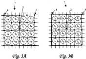
图3A、3B为说明图,显示GRID1关键点,且显示信息点之配置实例;Figures 3A and 3B are explanatory diagrams showing the key points of GRID1 and displaying configuration examples of information points;
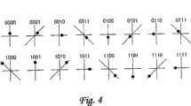
图4为视图,显示于GRID1中之信息点之配置实例,且显示该点状图样之信息点和此处定义数据之位显示之实例;Fig. 4 is a view showing an example of the configuration of information points in GRID1, and shows an example of the information points of the dot pattern and the bit display of defined data here;
图5A~C显示GRID1中之信息点及此处定义之数据之位显示之实例;Figures 5A-C show examples of information points in GRID1 and bit displays of data defined here;
图6A~D为视图,显示于GRID1中之点状图样之修改例;6A-D are views showing modified examples of dot patterns in GRID1;
图7为GRID3之点状图样之主视图;Fig. 7 is the front view of the dot pattern of GRID3;
图8为视图,显示于GRID3中信息点之配置实例;Figure 8 is a view showing an example of the configuration of information points in GRID3;
图9A~C为说明图,显示关键点及GRID3之信息点;Figures 9A-C are explanatory diagrams showing key points and information points of GRID3;
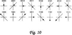
图10显示于GRID3之信息点和此处定义之数据之位显示之实例;Figure 10 shows an example of the bit display of information points and data defined here in GRID3;
图11A~F显示于GRID3之信息点3和此处定义之数据之位显示之实例;Figures 11A-F show an example of bit display at
图12A~D为视图,显示于GRID3中之点状图样之修改例;12A-D are views showing modified examples of dot patterns in GRID3;
图13A~C为GRID4之点状图样之主视图;13A-C are the front views of the dot pattern of GRID4;
图14为视图(1),显示GRID4中之信息点之一种定义方法;Fig. 14 is view (1), shows a kind of definition method of the information point in GRID4;
图15为视图(2),显示GRID4中之信息点之一种定义方法;Fig. 15 is view (2), shows a kind of definition method of the information point in GRID4;
图16A~C为视图(3),显示GRID4中之信息点之一种定义方法;Fig. 16A~C is view (3), shows a kind of definition method of the information point in GRID4;
图17A~C为视图(4),显示GRID4中之信息点之一种定义方法;Fig. 17A~C is view (4), shows a kind of definition method of the information point in GRID4;
图18A~C为说明图,显示于GRID4中通过光学读取装置读取信息点之读取顺序;18A-C are explanatory diagrams showing the reading sequence of reading information points by an optical reading device in GRID4;
图19为视图,有关键点配置来替代于GRID4之参考格点位置;Figure 19 is a view, with key point configuration to replace the reference grid position of GRID4;
图20为说明图,显示通过于GRID4中使用区别方法来读取信息点之一种读取方法;FIG. 20 is an explanatory diagram showing a reading method of reading information points by using a distinction method in GRID4;
图21A、B为视图(1),具有排列于GRID1之方向点;Figure 21A and B are views (1), with direction points arranged in GRID1;
图22A、B显示视图(2)之信息点之配置顺序,具有方向点排列于GRID1;Figure 22A and B show the arrangement order of the information points in view (2), with the direction points arranged in GRID1;
图23A、B为视图(1),具有排列于GRID3之方向点;Figure 23A and B are views (1), with direction points arranged in GRID3;
图24为视图(2),具有排列于GRID3之方向点;Figure 24 is view (2) with orientation points arranged in GRID3;
图25A、B为视图(1),显示GRID3之信息点之配置顺序;25A and B are views (1), showing the arrangement order of information points of GRID3;
图26A、B为视图,显示GRID3之方向点之配置顺序;26A and B are views showing the arrangement order of the direction points of GRID3;
图27A、B为视图(2),显示GRID3之信息点之配置顺序;27A and B are views (2), showing the arrangement order of the information points of GRID3;
图28A、B为视图(1),具有排列于GRID4之方向点;Figure 28A and B are views (1), with direction points arranged in GRID4;
图29为视图(1),显示GRID4之信息点之配置顺序;Figure 29 is a view (1), showing the configuration order of the information points of GRID4;
图30为视图(2),显示GRID4之信息点之配置顺序;Figure 30 is a view (2), showing the configuration order of the information points of GRID4;
图31A、B为视图,显示GRID4之方向点之配置顺序;Figure 31A and B are views showing the arrangement order of the direction points of GRID4;
图32为视图(3),显示GRID4之信息点之配置顺序;Figure 32 is a view (3), showing the configuration order of the information points of GRID4;
图33为视图(4),显示GRID4之信息点之配置顺序;Figure 33 is a view (4), showing the configuration order of the information points of GRID4;
图34A、B为说明视图(1)改变如何配置信息点及定义GRID1中之区块方向;Fig. 34A, B is to explain how to change the view (1) to configure information points and define the block direction in GRID1;
图35A、B为说明视图(2)改变如何配置信息点及定义GRID1中之区块方向;Fig. 35A, B is to explain how to change the view (2) to configure information points and define the block direction in GRID1;
图36A、B为说明视图(3)改变如何配置信息点及定义GRID1中之区块方向;Fig. 36A, B are to explain how to change the view (3) to configure information points and define the direction of blocks in GRID1;
图37A、B为说明视图(4)改变如何配置信息点及定义GRID1中之区块方向;Fig. 37A, B is to illustrate how view (4) changes how to configure information points and define the block direction in GRID1;
图38A~C为视图(1),显示当无法定义区块和方向时之一种配置实例;Figure 38A~C is a view (1), showing a configuration example when the blocks and directions cannot be defined;
图39为视图(2),显示当无法定义区块和方向时之一种配置实例;Figure 39 is a view (2), showing an example of a configuration when blocks and directions cannot be defined;
图40A、B为说明视图(1)改变如何配置信息点及定义GRID3中之区块方向;Fig. 40A, B are for explaining view (1) changing how to configure information points and define the block direction in GRID3;
图41A、B为说明视图(2)改变如何配置信息点及定义GRID3中之区块方向;Fig. 41A, B are for explaining view (2) changing how to arrange information points and define the block direction in GRID3;
图42A、B为说明视图(3)改变如何配置信息点及定义GRID3中之区块方向;Fig. 42A, B is to illustrate how view (3) changes how to configure information points and define the block direction in GRID3;
图43A、B为说明视图(4)改变如何配置信息点及定义GRID3中之区块方向;Fig. 43A, B is to illustrate how view (4) changes how to configure information points and define the block direction in GRID3;
图44A、B为说明视图(1)改变如何配置信息点及定义GRID4中之区块方向;Fig. 44A, B is to illustrate how to change the view (1) to configure information points and define the block direction in GRID4;
图45为说明视图(2)改变如何配置信息点及定义GRID4中之区块方向;Fig. 45 is to illustrate how view (2) changes how to configure information points and define the block direction in GRID4;
图46为说明视图(3)改变如何配置信息点及定义GRID4中之区块方向;Fig. 46 illustrates how to change the view (3) to configure information points and define the block direction in GRID4;
图47A~C为说明图,显示根据本实施例,方向点及信息点之判定演绎法则;47A-C are explanatory diagrams showing the deduction rules for determining direction points and information points according to this embodiment;
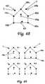
图48为说明图(1),依据如何配置参考点于具有格子以外之形状之区块中,来定义区块之方向;Figure 48 is an explanatory diagram (1), according to how to configure the reference point in the block with a shape other than the grid, to define the direction of the block;
图49为说明图(2),依据如何配置参考点于具有格子以外之形状之区块中,来定义区块之方向;Figure 49 is an explanatory diagram (2), according to how to configure the reference point in the block with a shape other than the grid, to define the direction of the block;
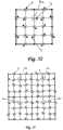
图50为说明图(1),当区块形状非为矩形区,且部分参考点重合部分参考格点时,依据如何配置参考点,来定义区块方向;Fig. 50 is an explanatory diagram (1). When the shape of the block is not a rectangular area, and part of the reference points coincide with part of the reference grid points, the direction of the block is defined according to how to configure the reference points;
图51为说明图(2),当区块形状非为矩形区,且部分参考点重合部分参考格点时,依据如何配置一参考点,来定义一区块方向;Fig. 51 is an explanatory diagram (2), when the shape of the block is not a rectangular area, and part of the reference points coincide with part of the reference grid points, a block direction is defined according to how to configure a reference point;
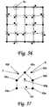
图52为说明图(1),于具有参考点配置于区块的四角隅之区块中,改变如何配置信息点,且定义区块之方向;Figure 52 is an explanatory diagram (1), in a block with reference points arranged at the four corners of the block, how to change the arrangement of information points, and define the direction of the block;
图53为说明图(2),于具有参考点配置于区块的四角隅之区块中,改变如何配置信息点,且定义区块之方向;Figure 53 is an explanatory diagram (2), in a block with reference points arranged at the four corners of the block, how to change the arrangement of information points, and define the direction of the block;
图54为说明图(3),于具有参考点配置于区块的四角隅之区块中,改变如何配置信息点,且定义区块之方向;Figure 54 is an explanatory diagram (3), in a block with reference points arranged at the four corners of the block, how to change the arrangement of information points, and define the direction of the block;
图55为说明图(4),于具有参考点配置于区块的四角隅之区块中,改变如何配置信息点,且定义区块之方向;Figure 55 is an explanatory diagram (4), in a block with reference points arranged at the four corners of the block, how to change the arrangement of information points, and define the direction of the block;
图56为说明图,于具有参考点配置于区块的四角隅之该区块中,通过随形部分参考点于格点来定义区块之方向;Fig. 56 is an explanatory diagram, in the block with reference points arranged at the four corners of the block, the direction of the block is defined by the reference point of the conformal part at the grid point;
图57为说明图,于形状与格子形状不同之区块中,改变参考点大小且定义区块方向;Fig. 57 is an explanatory diagram, in a block whose shape is different from that of a grid, change the size of the reference point and define the direction of the block;
图58为说明图,于形状具有呈格状之区块中,改变参考点大小且定义区块方向;Fig. 58 is an explanatory diagram, in which the size of the reference point is changed and the direction of the block is defined in a block shaped like a grid;
图59为说明图,显示配置于区块中心的信息点尺寸比其它信息点更大,被作为方向点之状态;Fig. 59 is an explanatory diagram showing the state that the information dot arranged in the center of the block is larger than other information dots and is used as a direction point;
图60为说明图,改变一信息点形状及定义一区块方向;Figure 60 is an explanatory diagram, changing the shape of an information point and defining a block direction;
图61为说明图,通过以其它信息点形状,改变配置于区块中心之该信息点形状来定义该区块之方向;Fig. 61 is an explanatory diagram, the direction of the block is defined by changing the shape of the information point arranged in the center of the block with other information point shapes;
图62为说明图,通过未配置信息点于位在区块中心之格区的虚拟格点上,来定义该区块方向;以及FIG. 62 is an explanatory diagram, defining the direction of the block by not disposing information points on the virtual grid points of the grid area located in the center of the block; and
图63为说明图,通过配置信息点于位在区块中心之该格区的该虚拟格点上,来定义该区块方向。FIG. 63 is an explanatory diagram in which the direction of the block is defined by arranging information points on the virtual grid point of the grid area located at the center of the block.
具体实施方式Detailed ways
其次将参考附图说明本发明。Next, the present invention will be described with reference to the drawings.
首先说明本发明使用之点状图样之基本原理,然后这些点状图样之方向点之实施例说明如后。Firstly, the basic principles of the dot patterns used in the present invention are described, and then the embodiments of the direction points of these dot patterns are described as follows.
(点状图样:GRID1之说明)(dot pattern: description of GRID1)
图1至图20为说明图,显示属于本发明之前提之一种点状图样的原理。图1至图20显示于GRID1中之点状图样,且包括关键点2。1 to 20 are explanatory diagrams showing the principle of a dot pattern which is one of the premise of the present invention. Figures 1 to 20 show the dot pattern in GRID1, including
但此关键点2与本发明之方向点不同,且非属本发明之特征。图1至图20所示关键点2与本发明之方向点间之差异将继续且于图21后说明其细节。But this
图1为显示GRID1之说明图,GRID1为根据本发明之点状图样之实例。图2为放大视图,显示点状图样之信息点和此处定义之信息之位显示之实例。图3A和图3B为说明图,显示取中于关键点(此关键点与本发明之方向点不同)排列之信息点。FIG. 1 is an explanatory diagram showing GRID1 which is an example of a dot pattern according to the present invention. Figure 2 is an enlarged view showing an example of the information dots of the dot pattern and the bit display of the information defined herein. FIG. 3A and FIG. 3B are explanatory diagrams showing information points arranged at a key point (this key point is different from the direction point of the present invention).
一种使用根据本发明之点状图样之信息输入和输出方法包括产生点状图样1、识别该点状图样1的手段、和由此点状图样1输出信息和程序之手段。换言之,通过摄影机提取点状图样1为影像数据,摄取参考格点4,然后当该点并非命中于参考格点4的适当位置时,摄取关键点2(此关键点2与本发明之方向点不同),然后摄取信息点3来数字化影像数据,以及摄取信息区来量化该信息,由于此种数值信息,信息和程序从此种点状图样1输出。例如,诸如语音和程序之信息从此种点状图样1输出至信息输出装置、个人计算机、PDA或蜂窝式电话等。An information input and output method using a dot pattern according to the present invention includes generating a
于产生根据本发明之点状图样1中根据预定法则来设置微小点用来辨识信息,诸如通过点密码产生演绎法则换言之关键点、信息点和参考格点4来辨识信息诸如语音。如图1所示,于显示该信息之点状图样1之区块中,参考格点4(5×5)取中于关键点2配置,信息点3环绕中心虚拟格点5配置,点5由四个参考格点4包围。于此区块中,定义任意数值信息。图1之实例显示点状图样1之四个区块(于粗体线内部)平行排列。但显然点状图样1并非限于4个区块。In generating the
可将一个对应信息和一个对应程序输出至一个区块;或可能将一个对应信息和一个对应程序输出至多个区块。One corresponding information and one corresponding program may be output to one block; or one corresponding information and one corresponding program may be output to a plurality of blocks.
当通过摄影机提取此点状图样1为影像数据时,参考格点4可校正摄影机镜头的失真、交叉拍摄、页面空间的胀缩、媒体表面的曲度、和印刷的失真。特别,获得一种校正函数,亦即(Xn,Yn)=f(Xn’,Yn’)来将四个失真的参考格点4转换成为原先的方形,且通过相同函数来校正信息点3,获得正确的信息点3的向量。When the
若参考格点4配置于点状图样1,则即使当具有高失真比的透镜之广用相机提取点状图样1的影像数据,因参考格点4可校正相机所造成的失真,故通过相机提取此点状图样1所得影像数据可被准确辨识。此外,即使倾斜的相机读取点状图样1的表面,此相机仍可准确辨识点状图样1。If the
如图1所示,关键点2为一点,配置有一个参考格点4位在配置于偏离预定方向的一个矩形中的多个参考格点之实质上中心。此关键点2为表示信息点3的一个区块之点状图样1之代表点。例如关键点2为位在向上偏离0.2毫米×0.2毫米的点状图样1的区块中心的该参考格点4。当信息点3表示X和Y坐标值之情况下,关键点2向下偏移0.2毫米×0.2毫米的位置变成坐标点。但此数值非仅囿限于此数值,而可根据点状图样1的区块大小来改变。As shown in FIG. 1 , the
信息点3为辨识各项信息的点。此信息点3环绕属于代表点的关键点2配置,让四个参考格点4所圈住的中心变成虚拟格点5,此信息点3配置于使用虚拟格点5做起点的由向量表示的终点。例如此信息点3被四个参考格点4所圈住。如图2所示,与虚拟格点5分开0.2毫米的该点具有由该向量所表示的方向和长度,故这些点排列成于顺时针方向以逐一45度旋转的八个方向来表示三个位。如此,通过一个区块的点状图样1可表示48位(3位×16)。
于附图所示实例中,点排列于八个方向来表示三个位,但非仅囿限于此,可通过将点排列于16个方向来表示4位,显然可得多项修改。In the example shown in the drawing, dots are arranged in eight directions to represent three bits, but not limited to this, 4 bits can be represented by arranging dots in 16 directions, obviously many modifications are possible.
较佳考虑视觉质量、相对于纸质的印刷准确度、相机分辨率、和最佳数字化,较佳关键点2、信息点3或参考格点4之直径约为0.1毫米。Preferably considering visual quality, printing accuracy relative to paper quality, camera resolution, and optimal digitization, the diameter of
此外,考虑有关各点2、3及4之影像拍摄区和错误辨识所需信息量,较佳参考格点4间的间隔约为1毫米×1毫米。考虑参考格点4和信息点3的错误辨识,较佳关键点2的偏移约为格子间隔之约20%。In addition, considering the image shooting area of each
较佳此信息点3与由四个参考格点4所圈出的虚拟格点5间的间隔距离约为相邻虚拟格点5间的间隔距离之15%至30%,原因在于信息点3与虚拟格点5间的距离比此间隔距离短,各点容易被视为一个大区块,而几乎无法当作点状图样1。相反地,若信息点3与虚拟格点5间的距离比此间隔距离长,则难以将该点识别为具有向量方向特性取中于任何相邻虚拟格点5的信息点3。Preferably, the distance between the
举例言之,如图3A所示,于信息点3中,当I1至I16环绕关键点2顺时针方向排列的间隔距离为1毫米时4毫米×4毫米表示3位×16=48位。For example, as shown in FIG. 3A , in the
此外,可提供子区块,其于该区块个别有独立信息内容,且不受其它信息内容的影响。图3B显示这些子区块,以及由四个信息点3所组成的子区块[I1,I2,I3,I4]、[I5,I6,I7,I8]、[I9,I10,I11,I12]、及[I13,I14,I15,I16]分别具有于信息点3所发展出的独立数据(3位×4=12位)。如此,通过提供子区块,容易以子区块为单位来检查错误。Furthermore, sub-blocks can be provided, which each have independent information content in the block and are not affected by other information content. Figure 3B shows these sub-blocks, and the sub-blocks [I1, I2, I3, I4], [I5, I6, I7, I8], [I9, I10, I11, I12] composed of four
较佳对每30度至90度均匀定义信息点3的向量方向(旋转方向)。It is preferable to uniformly define the vector direction (rotation direction) of the
图4显示信息点3之位显示之实例,及此处定义之数据,且显示其它组态。Figure 4 shows an example of the bit display of
此外,从由参考格点4所圈出的虚拟格点5中使用两种长的和短的信息点3,且定义八个向量方向,可表示4位。于此种情况下,期望相邻于长信息点的虚拟格点5间之距离约为25%至30%,而相邻于短信息点的虚拟格点5间之距离约为15%至20%。但长的和短的信息点3间的中心间隔较佳比这些信息点的直径更长。Furthermore, using two kinds of long and short information points 3 from the virtual grid points 5 circled by the reference grid points 4, and defining eight vector directions, 4 bits can be represented. In this case, it is expected that the distance between the virtual grid points 5 adjacent to the long information point is about 25% to 30%, and the distance between the virtual grid points 5 adjacent to the short information point is about 15% to 20%. %. However, the center distance between the long and
较佳由四个参考格点4圈出的信息点3于考虑视觉质量时作为一点。但当忽略视觉质量,增加信息量的情况下,通过将一个位配置于一个向量,且通过多点来表示信息点3,信息点3可有较多信息。例如于同心的八方向向量中,28块信息可由四个参考格点4所圈出的信息点3来表示,通过一个区块的16块信息点可表示2128。Preferably, the
图5显示信息点之位显示及该处定义的数据之实例。图5A显示两点的配置,图5B显示四点的配置,以及图5C显示五点的配置。Figure 5 shows an example of the bit display of an information point and the data defined there. Figure 5A shows a two-dot configuration, Figure 5B shows a four-dot configuration, and Figure 5C shows a five-dot configuration.
图6显示点状图样之一个修改例。图6A为六个信息点配置型别之示意图,图6B为九个信息点配置型别之示意图,图6C为12个信息点配置型别之示意图,第6D图为36个信息点配置型别之示意图。Fig. 6 shows a modified example of the dot pattern. Figure 6A is a schematic diagram of six information point configuration types, Figure 6B is a schematic diagram of nine information point configuration types, Figure 6C is a schematic diagram of 12 information point configuration types, and Figure 6D is a schematic diagram of 36 information point configuration types The schematic diagram.
图1和图3所示之点状图样1显示16(4×4)信息点3配置于一个区块的实例。但此信息点3非仅限于16块信息配置于一个区块的情况,多种变化皆属可能。举例言之,根据所需信息量大小或相机的分辨率,如图3A所示,6(2×3)信息点3配置于一个区块,如图3B所示,9(3×3)信息点3配置于一个区块;如图3C所示,12(3×4)信息点3配置于一个区块;或如图3D所示,36信息点3配置于一个区块。The
(点状图样:GRID3之说明)(Dot pattern: Description of GRID3)
其次将说明GRID3。Next, GRID3 will be explained.
图7为说明图,显示根据本发明之一种点状图样之实例;图8为放大视图,显示点状图样之信息点之位显示和其中定义之数据之实例;以及图9A、9B及9C为说明图,显示关键点和信息点之配置。7 is an explanatory diagram showing an example of a dot pattern according to the present invention; FIG. 8 is an enlarged view showing an example of bit display of information points of the dot pattern and data defined therein; and FIGS. 9A, 9B and 9C It is an explanatory diagram showing the configuration of key points and information points.
使用根据本发明之点状图样之信息输入与输出方法通过辨识点状图样1之手段和由此点状图样1输出信息和程序之手段所形成。The information input and output method using the dot pattern according to the present invention is formed by means of recognizing the
换言之,通过相机提取点状图样1为影像数据,摄取参考格点4,然后判定为虚拟参考格点6之位置,连接这些虚拟参考格点6之线定义为参考网格线7。然后于无任何点设置于虚拟参考格点6的位置的情况下,参考格点4原先应该位在此参考网格线7上,摄取环绕此虚拟参考格点6的点,此点判定作为关键点2(该区块四角的夹角部分)。其次设定于水平方向和垂直方向的网格线8a和8b连接虚拟参考格点6,网格线的交叉点定义为虚拟格点11(第一虚拟格点)。此外,搜寻环绕此虚拟格点11的点,摄取出信息点3,由距该虚拟格点11的距离和方向定义。In other words, the
此外,假设斜向网格线8c于斜向连接虚拟参考格点6,这些斜向网格线8c的交叉点也定义为虚拟参考格点12(第二虚拟格点)。然后也搜寻环绕虚拟参考格点12的该点,摄取出由距离该虚拟参考格点12的距离和方向定义的信息点3。In addition, assuming that the
其次,依据关键点2距虚拟参考格点6或虚拟格点11的方向,来判定区块的方向。例如当关键点2从虚拟格点偏移成+y方向,假设纵向为正常状态,则可辨识于该区块内部的信息点3。Secondly, the direction of the block is determined according to the direction of the
此外,若关键点2从虚拟参考格点6或虚拟格点11偏离成-y方向,假设以区块的中心为中心,区块旋转180度的方向为正常状态,则可辨识区块内部的信息点3。In addition, if the
此外,若关键点2从虚拟参考格点6或虚拟格点11偏离成-x方向,假设以区块的中心为中心,区块旋转顺时针方向90度的方向为正常状态,则可辨识区块内部的信息点3。In addition, if the
此外,若关键点2从虚拟参考格点6或虚拟格点11偏离成+x方向,假设以区块的中心为中心,区块旋转逆时针方向90度的方向为正常状态,则可辨识区块内部的信息点3。In addition, if the
若通过光学读取手段读取的点状图样1之影像积取于图框缓冲器,则此光学读取手段的中央处理单元(CPU)可分析图框缓冲器该点,可对个别信息点3译码数值,该数值由个别信息点3从虚拟格点11和虚拟参考格点12之距离和方向定义。然后这些数值由显示装置输出,语音输出手段和影像输出手段相对于以xy坐标或密码而储存于该光学读取装置或个人计算机的内存之信息作核对;读取出与该xy坐标或密码相对应的语音、影像、动画影像、文字和程序等。If the image of the
于根据本发明之点状图样1的产生中,通过点密码产生演绎法则来辨识信息诸如语音的微小点,换言之关键点2、信息点3、及参考格点4根据预定法则配置。In the generation of the
如图7所示,于印刷材料媒体等表面上,成形为方形或矩形的一个矩形区定义为一个区块。然后于参考网格线7的某个间隔提供虚拟参考格点6,以组构区块的图框之纵向线和横向线定义为参考网格线7(图1的粗体线表示的线),参考格点4配置于虚拟参考格点6上。其次让连接虚拟参考格点6且平行于参考网格线7的线作为网格线8a和8b,网格线8a与8b的交叉点定义为虚拟格点11(第一虚拟格点)。As shown in FIG. 7 , on the surface of a printing material medium or the like, a rectangular area shaped as a square or a rectangle is defined as a block. Then provide a virtual
此外,设定斜向连接虚拟参考格点6的斜向网格线8c,这些网格线8c的交叉点也定义为虚拟格点12(第二虚拟格点)。Furthermore,
通过基于以此方式设定的虚拟格点11和虚拟参考格点12,配置具有上述这些距离和方向的一个或多个信息点3,产生点状图样。By arranging one or
当通过相机提取此点状图样1为影像数据时,参考格点4可校正相机镜头的失真、交叉拍摄、页面空间的扩大和缩小、媒体表面的弯曲、和印刷失真。特别,获得校正函数,亦即(Xn,Yn)=f(Xn’,Yn’)来将失真的四个虚拟格点转成原先的方形,且通过相同函数校正信息点3,获得正确的信息点3之向量。When the
若参考格点4配置于点状图样1,通过相机提取此点状图样1所得的影像数据可被准确辨识,即使当具有高失真比的镜头之普遍相机来提取点状图样1的影像数据亦如此,原因在于参考格点4可校正由相机所造成的失真。此外,即使倾斜的相机读取点状图样1的表面,此相机仍可准确辨识点状图样1。If the
如图7所示,关键点2为一点相对于位在配置成矩形的虚拟格点之实质中心的一个虚拟格点11之距离和方向来配置的一点。此关键点2为一个区块表示一个信息点集合的一个单元之点状图样1的代表性点。例如关键点2从位在点状图样区块中心的虚拟格点11向上偏移0.2毫米×0.2毫米。如此于信息点3表示从该虚拟格点的X坐标值和Y坐标值时,从关键点2向下分开0.2毫米的距离变成虚拟格点(坐标点)。但此数值0.2毫米非仅囿限于此,而可根据点状图样1的区块的大小来改变。As shown in FIG. 7 , the
信息点3为辨识各项信息的点。于图12中,此信息点3环绕作为代表性点的关键点2排列,让四个虚拟格点11(第一虚拟格点)圈出的中心变成虚拟参考格点12(第二虚拟格点),此信息点3配置于使用虚拟参考格点12作起点的向量所表示的终点。例如此信息点3由虚拟格点11和12圈出。如图8所示,距上述这些虚拟格点11和12 0.2毫米的分开点具有由该向量所表示的方向和长度,故这些点排列于顺时针方向以45度×45度旋转的八个方向来表示3位。
根据该图,可通过一个区块的点状图样1来表示48位(3位×16)。According to this figure, 48 bits (3 bits×16) can be represented by
于该图所示实例中,点排列于八个方向来表示3位,但也可通过将点排列成16个方向来表示4位,并非限制性,显然可做出多项修改。In the example shown in the figure, dots are arranged in eight directions to represent 3 bits, but it is also possible to represent 4 bits by arranging dots in 16 directions, which is not restrictive and obviously various modifications can be made.
此外,于图7中,于全部虚拟格点中,使用此虚拟格点作为起点,信息点排列于终点位置,但非限制性,可依据是否有点排列于虚拟格点上来定义信息。例如,若该点排列于虚拟格点上,信息可定义为「1」;若该点未排列于虚拟格点上,则信息可定义为「0」。In addition, in FIG. 7 , among all the virtual grid points, the virtual grid point is used as the starting point, and the information points are arranged at the end position, but it is not limiting, and the information can be defined according to whether the points are arranged on the virtual grid points. For example, if the point is arranged on the virtual grid point, the information can be defined as "1"; if the point is not arranged on the virtual grid point, the information can be defined as "0".
较佳考虑视觉质量、相对于纸张质量的印刷准确度,相机分辨率和最佳数字化,信息点3或参考格点4的直径约为0.1毫米。Preferably considering visual quality, printing accuracy relative to paper quality, camera resolution and optimum digitization, the
此外,就影像拍摄区考虑所需信息量、和各点2、3及4的错误概念,较佳参考格点4的间隔距离约为1毫米×1毫米。考虑参考格点4和信息点3的错误概念,较佳关键点2的偏移约为格子间隔距离之20%。In addition, considering the amount of information required for the image shooting area and the misconceptions of the
较佳信息点3与虚拟格点11或虚拟参考格点12间之间隔距离约为相邻虚拟格点11和虚拟参考格点12间之距离之15%至30%,原因在于若信息点3与虚拟格点11及虚拟参考格点12间之间隔距离比此间隔距离短,则上述这些点容易被视为一个大区块,各点于点状图样1上几乎不可见。相反地,若信息点3与虚拟格点11和虚拟参考格点12之间距比此间隔距离更长,则难以将该点识别为信息点3,具有向量方向特性取中于任何相邻的虚拟格点11和12。The distance between the
图9显示于该区块内部之信息点3之读取顺序,附图中圈出的数字表示每个虚拟格点11和每个虚拟参考格点12配置信息点3的面积。FIG. 9 shows the reading sequence of the
举例言之,于图9A中,(1)至(25)环绕(1)(如此表示附图中被圈出的数字「1」,后文亦同)于顺时针方向排列,该(1)位在区块的中心。于此种情况下,例如格子间隔为1毫米,3位×1625=4875位以4毫米×4毫米表示。For example, in FIG. 9A , (1) to (25) surround (1) (this represents the circled number "1" in the drawing, and the same applies hereinafter) in a clockwise direction, and the (1) at the center of the block. In this case, for example, the grid interval is 1 mm, and 3 bits×1625=4875 bits are represented by 4 mm×4 mm.
于图9B中,于通过纵向旋转将信息点(1)至(4)排列于区块左上的矩形区后,信息点(5)至(7)排列于水平网格线与垂直网格线的交叉点。In FIG. 9B, after the information points (1) to (4) are arranged in the rectangular area on the upper left of the block by vertical rotation, the information points (5) to (7) are arranged in the horizontal grid line and the vertical grid line. intersection.
于图9C中,于通过纵向旋转将信息点(1)至(16)排列于区块左上的矩形区后,信息点(17)至(25)排列于水平网格线与垂直网格线的交叉点。In FIG. 9C, after the information points (1) to (16) are arranged in the rectangular area on the upper left of the block by vertical rotation, the information points (17) to (25) are arranged in the horizontal grid line and the vertical grid line. intersection.
图10显示信息点之位显示及此处定义之数据之实例,显示其它组态。Figure 10 shows an example of the bit display of the information point and the data defined here, showing other configurations.
此外,由参考格点4所包围的虚拟格点11、12中使用两种短信息点3(图10之上排)和长信息点3(图10之下排),且定义八个向量方向,可表示4信息点。此种情况下,期望相邻于长信息点的虚拟格点间距约为25%至30%,相邻于短信息点的虚拟格点间距约为15%至20%。但长信息点3与短信息点3问的中心间隔距离较佳比这些点的直径更长。In addition, two kinds of short information points 3 (upper row in FIG. 10 ) and long information points 3 (lower row in FIG. 10 ) are used in virtual grid points 11 and 12 surrounded by reference grid points 4, and eight vector directions are defined , which can represent 4 information points. In this case, it is expected that the distance between virtual grid points adjacent to long information dots is about 25% to 30%, and the distance between virtual grid points adjacent to short information dots is about 15% to 20%. But the distance between the centers of the
考虑由四个虚拟格点11、12包围的信息点3为考虑视觉质量时的点。但于忽视视觉质量,增加信息量的情况下,通过配置一个位与一个向量,且以多点来表示信息点3,信息点3可具有较多信息。例如于同心八方向向量中,28块信息可以四个参考格点4包围的信息点3表示,2128可以一个区块的16块数据点表示。Consider an
图11显示信息点3之位显示和此处定义之数据之实例。图11A显示两点之配置,图11B显示四点之配置,图11C至11E显示五点之配置及图11F显示七点之配置。Figure 11 shows an example of the bit display of
图12显示点状图样之一个修改例。图12A为八个信息点3于区块中的排列形式之示意图,图12B为13个信息点3于区块中的排列形式之示意图,图12C为18个信息点3于区块中的排列形式之示意图,以及图12D为41个信息点3于区块中的排列形式之示意图。Fig. 12 shows a modified example of the dot pattern. Figure 12A is a schematic diagram of the arrangement of eight
前述图7和图9所示之点状图样1显示一个实例,25块信息点3排列于一个区块。但此信息点3非仅限于25块排列于一个区块的情况,多项变化皆属可能。例如根据所需信息量或相机分辨率,如第12A图所示,8块信息点3排列于一个区块;如图12B所示,13块信息点3排列于一个区块;如图12C所示,18块信息点3排列于一个区块:或如图12D所示,41块信息点3排列于一个区块。The
(点状图样:GRID4之说明)(Dot pattern: Description of GRID4)
其次将说明GRID4。Next, GRID4 will be explained.
图13特别显示根据本发明之实施例之一种点状图样。图13A显示4×4格之点状图样,图13B显示4×4格之点状图样,图13B显示5×4格之点状图样,及图13C显示6×4格之点状图样。Fig. 13 particularly shows a dot pattern according to an embodiment of the present invention. Figure 13A shows a dot pattern of 4*4 grids, Figure 13B shows a dot pattern of 4*4 grids, Figure 13B shows a dot pattern of 5*4 grids, and Figure 13C shows a dot pattern of 6*4 grids.
于图13A中,首先,提供于水平方向和垂直方向之参考网格线7a至7d来组成一个方块,虚拟格点13配置于方块内部的某个间隔距离。In FIG. 13A, firstly,
此外,参考网格线7a至7d和虚拟格点13实际上并未打印于页面空间(媒体空间),反而于计算机的影像内存上的点状图样配置时或点状图样读取时虚拟设定。In addition, the
其次配置参考格点4于横向的上和下参考网格线7a至7d的虚拟格点14上。Secondly, the reference grid points 4 are arranged on the virtual grid points 14 of the upper and lower
其次,假设于水平方向和垂直方向之网格线8a和8b连接虚拟格点13,网格线8a和8b的交叉点系以相同方式定义为虚拟格点13。Next, assuming that the
其次,对各个虚拟格点13,配置具有相对于虚拟格点13的距离和方向的一个或两个信息点3,产生点状图样。此外,于图13中,对虚拟格点13配置一个信息点3。Secondly, for each
图13A显示信息点3配置有纵向4格和横向4格(4×4格)的情况;图13B显示5×4格情况;及图13C显示6×4格的情况。FIG. 13A shows a case where
图14显示信息点3的定义,该值定义于信息点3环绕虚拟格点13的方向。本图中,通过配置相对于通过虚拟格点的网格线,以顺时针方向逐一45度旋转的八个方向之信息点,共可定义八种信息(于2记数法系统的000至111,3个位)。FIG. 14 shows the definition of the
此外,图15中,距离分成顺时针方向的两个阶段,共可定义16种信息(于2之记数法系统中),换言之信息0000至1111(4位)。In addition, in FIG. 15, the distance is divided into two stages in the clockwise direction, and a total of 16 kinds of information can be defined (in the notation system of 2), in other words,
图16显示多个信息点3环绕虚拟格点13配置于一个同心圆上的情况。通过当有点于其上时,该位置定义为「1」,而当无任何点于其上时定义该位置为“0”,可定义8位。换言之,可以位在垂直方向的该点定义为第一位,顺时针方向定义位信息。FIG. 16 shows a situation in which a plurality of information points 3 are arranged on a concentric circle around the
图17显示可定义两个同心圆和16位的情况。如此就一个虚拟格点13而言可定义大量信息。Figure 17 shows that two concentric circles and 16 bits can be defined. In this way, a large amount of information can be defined for one
图18为说明图,显示通过光学读取装置读取信息点3的读取顺序。该图中,圈出数字的为方便目的而使用,实际上点状图样如图13A至图13C之说明。FIG. 18 is an explanatory diagram showing a reading sequence for reading
图18A中,首先沿于纵向左侧的参考网格线7c3读取各个虚拟格点的信息点(圈出数字(1)至(3)),然后通过从前述旋转,读取于纵向的次一网格线7b上的虚拟格点13(圈出数字(4)至(6))。如此串行进行各个虚拟格点13的读取。In Fig. 18A, first read the information points of each virtual grid point along the reference grid line 7c3 on the left side of the longitudinal direction (circle the numbers (1) to (3)), and then read the second time in the longitudinal direction by rotating from the aforementioned A
各格的读取于前文说明中,于纵向由网格线7b左侧旋转进行,但显然配置和读取信息的格子顺序可任意设定。The reading of each grid is carried out in the above description, in the longitudinal direction by the left rotation of the
图19显示关键点2设置于参考网格线上的虚拟格点13上,而非设置于参考格点4上。关键点2相对于于参考网格线7a中央位置的虚拟格点13设置于向上偏离位置。FIG. 19 shows that the
通过这些关键点2,可定义点状图样之方向。Through these
图20为说明图,显示通过使用不同方法读取信息点3之方法。后文于图中由方形框出的数字系以[]表示,图中以圆圈圈出的数字以()表示。FIG. 20 is an explanatory diagram showing a method of reading an
换言之,图20中,数值[1]由4×4格的(4)信息点之值与(1)信息点之值间之差表示。In other words, in FIG. 20, the value [1] is represented by the difference between the value of (4) information dots and the value of (1) information dots in a 4×4 grid.
以相同方式,[2]可以(5)与(2)间之差表示,以及[3]可以(6)与(3)间之差表示。此外,[4]至[12]可以相同方式表示。In the same way, [2] can be expressed as the difference between (5) and (2), and [3] can be expressed as the difference between (6) and (3). Also, [4] to [12] can be represented in the same manner.
至[12]可以下列信息点间之差表示。Up to [12] can be expressed as the difference between the following information points.
=(4)-(1)=(4)-(1)
=(5)-(2)=(5)-(2)
=(6)-(3)=(6)-(3)
=(7)-(4)=(7)-(4)
=(8)-(5)=(8)-(5)
=(9)-(6)=(9)-(6)
=(10)-(7)=(10)-(7)
=(11)-(8)=(11)-(8)
=(12)-(9)=(12)-(9)
=(13)-(10)=(13)-(10)
=(14)-(11)=(14)-(11)
=(15)-(12)=(15)-(12)
通过使用此种差值方法,就一个真值而言可产生多个不同的点状图样来改良安全性。By using this difference method, multiple different dot patterns can be generated with respect to a true value to improve security.
(GRID1中之方向点的说明)(Description of direction points in GRID1)
前述图1至图20主要说明由本发明之发明人所提示之一种点状图样之实例。于后文说明中,将说明通过方向点定义区块之方向而未使用关键点2的情况之进一步细节。The aforementioned FIGS. 1 to 20 mainly illustrate an example of a dot pattern proposed by the inventor of the present invention. In the following description, further details of the case where the direction of the block is defined by the direction point without using the
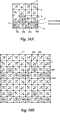
图21A及图21B为方向点21配置于图1至图20所述GRID1的点状图样的基元上之实例。FIG. 21A and FIG. 21B are examples in which direction points 21 are arranged on the dot pattern primitives of GRID1 described in FIG. 1 to FIG. 20 .
于本实例中,信息依据由参考格点4环绕的该区如何偏离中点定义。如此,信息点3可配置于全部格区,但方向点21只配置于3×3块的中心格区上。In this example, the information is defined in terms of how the area surrounded by the
于配置方向点21之区上,方向点表示方向,信息定位为于水平方向和垂直方向偏离中心点。换言之,图21A中,因方向点21配置于从中心偏离向上(+Y方向)的位置,故已知此区块为向上。于此方向点21配置于从中心向下偏移的位置(-Y方向)的情况下,已知此区块为向下。同理,于此方向点21配置于从中心向左偏移的位置(-X方向)的情况下,已知此区块为向左;以及于此方向点21配置于从中心向右偏移的位置(+X方向)的情况下,已知此区块为向右。On the area where the
此外,于方向点21以外之格区,信息通过让方向点从中心点斜向偏移来定义。此种信息之定义方法说明如前,故于此处删除其说明。In addition, in the grid area other than the
此外,此格区具有与其它格区(配置方向点21的格区)不同的方向标准,当方向点配置于其中心时,定义区块于方向点21的方向;而当此具有不同方向标准的格区配置于区块的其它区(方向区)时,由于此配置方向可定义方块方向(参考图40)。此外,提供多个具有不同方向标准的格区,因其配置模型而可定义区块的方向(参考图34至图37)。于此种情况下,只有通过配置具有不同方向标准的格区,可定义区块的方向,因此并非经常性需要让配置于此格区的信息点3符合区块的方向。容后详述。In addition, this grid area has a direction standard different from other grid areas (the grid area where the
如此,通过于格区上于水平方向和垂直方向配置信息点3,以及于其它区上于斜向配置信息点3,不会牺牲参考格点的相等空间性质,原因在于并无任何参考格点4因关键点2而偏离。因此可简化点状图样之读取演绎法则。此外,信息点3可于方向区配置,故可定义区块方向而未牺牲信息点3。此外,即使配置方向点21时,信息可通过偏离中心点的量(偏离中心点的长度)定义,信息点3也可用作为方向点21。In this way, by arranging the information points 3 in the horizontal direction and the vertical direction on the grid area, and disposing the information points 3 in the oblique direction on other areas, the equal space properties of the reference grid points will not be sacrificed, because there is no
图47为说明图,显示方向点和信息点之判定演绎法则。Fig. 47 is an explanatory diagram showing the judgment and deductive rules of direction points and information points.
当判定方向点21和信息点3时,将进行下列程序。When determining
(1)计算s=|I0-I2|(1) Calculate s=|I0-I2|
(2)计算t=|I3-I1|(2) Calculate t=|I3-I1|
(3)计算s-t(3) Calculate s-t
(4)若s-t不小于预定值P,则该点被判定为信息点;而若s-t小于预定值P,则该点判定为方向点。(4) If s-t is not less than the predetermined value P, the point is determined as an information point; and if s-t is less than the predetermined value P, the point is determined as a direction point.
特别于图47A之情况下,当确立s-t=|I0-I2|-|I3-I1|=|I0-I2|,|I0-I2|≥P时,该点为信息点。Especially in the case of FIG. 47A, when it is established that s-t=|I0-I2|-|I3-I1|=|I0-I2|, |I0-I2|≥P, the point is an information point.
于图47B之情况下,当确立s-t=|I0-I2|-|I3-I1|=0,0<p时,该点为方向点。In the case of FIG. 47B, when it is established that s-t=|I0-I2|-|I3-I1|=0, 0<p, the point is a direction point.
此外,p值可任意设定,较佳约为120像素2,但并非囿限于此一数值。In addition, the value of p can be set arbitrarily, preferably about 120
图21A显示由9块格区所形成的一个区块(3×3=9);以及图21B显示区块于水平方向和垂直方向以2×2排列之实例。FIG. 21A shows a block formed by 9 grid areas (3×3=9); and FIG. 21B shows an example in which the blocks are arranged in 2×2 in the horizontal direction and the vertical direction.
图22A及图22B显示与图21A及图21B相对应之信息点3之各个格区之排列顺序。信息点3之排列顺序并非囿限于此。FIG. 22A and FIG. 22B show the arrangement order of each grid area of the information dot 3 corresponding to FIG. 21A and FIG. 21B . The arrangement order of the information points 3 is not limited thereto.
(GRID3:方向点之配置实例)(GRID3: configuration example of direction points)
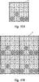
图23A及图23B显示方向点21应用于其它点状图样(GRID3)之情况。23A and 23B show the situation where the
于GRID1中,信息点3配置于由四个参考格点所包围的该区,但于GRID3中,信息点3也配置于参考格点的位置。于本实例中,可配置方向点21于区块内部聚焦于任何参考格点。In GRID1,
图23A中,位在16块格区(4×4=16)的左上格区的右下的参考格点定义为方向点21的配置位置。当方向点21配置于此位置时,位在环绕此区块(23a、23b、23c)中心旋转90度位置时,方向点21无法判定信息点3是否配置于方向点21的相同方向(水平方向和垂直方向)。因此可能无法定义区块方向。In FIG. 23A , the reference grid point located at the lower right of the upper left grid area of the 16-block grid area (4×4=16) is defined as the arrangement position of the
因此,于方向点21配置位置以外的参考格点,信息点配置于斜向。因此变成容易搜寻方向点21。Therefore, information dots are arranged obliquely at reference grid points other than where the
于图23A中,当该点配置于方向点21的位置时,定义此区块为向上,换言之,该点配置于从本图中之参考格点向上时,此区块定义为向上。In FIG. 23A, when the point is arranged at the position of the
但本发明非仅限于区块方向定义于点的位置本身,如本图所示,也可通过配置一区,于该区的点于区块本身的左上,配置于水平方向和垂直方向,也可定义区块的方向。于此种情况下,并非经常性配置于此区的点必须符合区块的方向,而可设置于从参考格点的右、左、和下方向。如此,通过事先定义与其它信息点3为不同方向标准的信息该区(方向区21a:本方向区21a中,信息点3配置于参考格点的水平方向和垂直方向,该区具有其它区的网格线的交叉点来作为参考格点,该点配置于斜向)于该区块中的预定位置,可定义该区块的方向。换言之,若方向区21a配置于左上,则此区块为向上。此外,因区块方向只可定义于此区(方向区21a)的配置位置,故唯有于相对于参考格点的任何方向为与其它信息点的不同方向时,此区(方向区21a)的信息点3才可配置于该方向。However, the present invention is not limited to the direction of the block defined by the position of the point itself. As shown in this figure, it is also possible to configure a region, and the points in this region are arranged on the upper left of the block itself, and are arranged in the horizontal and vertical directions. The orientation of the blocks can be defined. In this case, the points that are not always arranged in this area must conform to the direction of the block, and can be set in the right, left, and down directions from the reference grid point. Like this, by defining in advance and
此外,图23A中,方向区21a可与欲配置于方向点21的方向(水平方向和垂直方向)的其它参考点的信息点3之配置方向(斜向)区别。但如图23B所示,本实施例非仅限于此点,因相对于参考格点的长度故,可识别方向点21。本图中,只有方向点21与参考格点间的距离设定为较长,于其它位置(23a、23b、23c),信息点3与参考格点间之距离皆设定为较短。In addition, in FIG. 23A , the
图24显示前述情况,GRID3的两个点状图样组配于水平方向和垂直方向,图25A与图25B显示与此相对应之信息点3的排列顺序。FIG. 24 shows the aforementioned situation. The two dot patterns of GRID3 are arranged in the horizontal direction and the vertical direction. FIG. 25A and FIG. 25B show the sequence of arrangement of
此外,于图24所示的情况,各点配置于相对于参考点的上、下、右、和左方向之该区(方向区21a)配置于该区块的左上,可识别此区块方向。In addition, in the situation shown in FIG. 24, each point is arranged in the upper, lower, right, and left directions relative to the reference point. The area (
图26A和图26B显示方向点21配置于GRID3之点状图样的区块中心之实例。FIG. 26A and FIG. 26B show an example in which the
如此,通过配置方向点21于区块中心,可自由配置信息点3于其它格点上的水平、垂直和斜向方向。In this way, by arranging the
图27A和图27B分别与图26A和图26B相对应,其显示信息点3的排列顺序。FIG. 27A and FIG. 27B correspond to FIG. 26A and FIG. 26B , respectively, and show the arrangement order of
(GRID4:方向点之配置实例)(GRID4: configuration example of direction points)
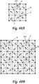
图28至图33显示方向点进一步应用于其它点状图样1(GRID4)之情况。28 to 33 show the situation where the direction point is further applied to other dot pattern 1 (GRID4).
图28A中,于此点状图样(GRID4)上,参考格点4以均匀间隔设置于区块上方和下方的横向网格线28A及28B上,信息点3配置取中于此参考格点4以外的格点上。In Fig. 28A, on this dot pattern (GRID4), reference grid points 4 are set at even intervals on the horizontal grid lines 28A and 28B above and below the block, and
于此种点状图样上,于位在上网格线28a与下网格线28b间的中点的次一阶中心网格线28c的预定参考格点区,信息点3使用此参考格点作为起点而配置于水平方向和垂直方向,此区变成方向区21a。On this dot pattern, in the predetermined reference grid point area of the next-order
于此方向区21a,配置信息点3的方向标准与属于同一网格线的参考格点的配置标准不同。换言之,于其它参考格点该区,信息点3从参考格点朝斜向方向配置。换言之,于方向区21a,信息点3从参考格点于水平方向和垂直方向配置。In this
如此,于方向区21a配置于相对于中心网格线28c的上方的情况下,可识别此区块为向上。In this way, when the
于方向区21a,信息点3可任意配置于水平方向和垂直方向,但显然于此方向具有方向区21a的方向点21可配置成符合区块的方向。In the
此外,当方向区21a设置于中心网格线28c的情况下,配置于此方向区21a之点显示区块方向作为方向点21。In addition, when the
于此种点状图样(GRID4)中,当任何格点位置被判定为方向点21时,以位在上网格线28a与下网格线28b间的中点中心网格线28c为中心之对称线之格点的信息点3与方向点21以不同方式配置。换言之,方向点21配置成由格点于上、下、右、和左方向偏移;而于与该格点对称之对称在线的格点,信息点3于斜向偏离之格点配置。In this kind of dot pattern (GRID4), when any grid point position is determined as a
于此种点状图样(GRID4)上,因参考格点4只有以均匀间隔距离配置于上网格线28a及下网格线28b,故可识别此区块的纵向方向。其次,搜寻相对于中心网格线28c于对称位置,于斜向和纵向配置的各点之该区。此处搜寻之纵向点变成方向点21。On this kind of dot pattern (GRID4), since the reference grid points 4 are only arranged on the
图28B为视图,显示如前述的两个区块于水平方向和垂直方向平行配置之状态。FIG. 28B is a view showing a state in which two blocks are arranged in parallel in the horizontal direction and the vertical direction as described above.
此外,图29A为说明图,显示如何配置本点状图样(GRID4)之信息之实例。根据本实例,信息由各点之差值定义。于本说明书中,假设[1]表示图中由方框框出的数字1,而(1)表示图中圈出的数字1。此处例如第一信息[1]由位在(4)的信息点3之值减位在(1)的信息点3之值所得数值定义。如图所示,唯有于其上配置方向点21的该格点未被用作为信息点3,但可通过距格点的长度差来获得此方向点21的信息。In addition, FIG. 29A is an explanatory diagram showing an example of how to arrange the information of this dot pattern (GRID4). According to this example, the information is defined by the difference between the points. In this specification, it is assumed that [1] represents the
此外,替代方向点21,如参考图28A所述,显然信息点3可配置于此区作为方向区21a。In addition, instead of the
图30之上图显示图29所示之点状图样之区块于水平方向和垂直方向分别逐二连接的情况;图30之下图显示此值的计算。The upper figure of FIG. 30 shows the situation that the blocks of the dot pattern shown in FIG. 29 are connected one by one in the horizontal direction and the vertical direction respectively; the lower figure of FIG. 30 shows the calculation of this value.
图31A和图31B为方向点21配置于GRID4点状图样之区块中心的实例。FIG. 31A and FIG. 31B are examples in which the
如此通过配置方向点21于该区块中心,可自由配置信息点3于水平方向和垂直方向的其它格点。By arranging the
图32至33显示与图31相应的信息的配置。32 to 33 show configurations of information corresponding to FIG. 31 .
(GRID1:修改的图样)(GRID1: modified pattern)
图34A和图34B只通过将只有9块(3×3=9)格区组构的该区块之点状图样中之特定格区(方向区),将只有该区的信息点3之配置方向改成于GRID1点状图样的其它格区(方向区)的配置方向来定义区块的方向。Fig. 34A and Fig. 34B only will only have the disposition of the information dot 3 of this district by the specific grid area (direction area) in the dot pattern of this block that only has 9 (3*3=9) grid area structures The direction is changed to the configuration direction of other grid areas (direction areas) of the GRID1 dot pattern to define the direction of the block.
换言之,于图34A中,信息点3相对于左下格区34a、中心格区34b、及右下格区34c的中心配置于水平方向和垂直方向;而于其它格区,信息点3从其中心配置于斜向。如此通过配置格区34a、34b、及34c,可辨识为此区块从连接这些格区的三角形向上,换言之,顶点34b相对于底边34a和34c之关系。In other words, in FIG. 34A, the
如此,可依据格区34a、34b、及34c(其中信息点3由其中心于水平方向和垂直方向配置)之配置关系(此处为三角形)来定义区块的方向。其中改变信息点3于该区块的配置方向。通过此信息点3可配置于该区块的全部格区,而未牺牲关键点的格区。In this way, the direction of the block can be defined according to the arrangement relationship (triangular here) of the grid areas 34a, 34b, and 34c (wherein the
此外图34B显示图34A所示各区块于水平方向和垂直方向以逐二方式连接的状态。In addition, FIG. 34B shows a state in which the blocks shown in FIG. 34A are connected in a two-by-two manner in the horizontal direction and the vertical direction.
图35A和图35B显示信息点3以与图34A和图34B相对应之方式配置之信息。FIGS. 35A and 35B show information in which
图36A为图34A的修改。于16格区(4×4=16)组成区块的点状图样中,只有于特定格区36a、36b、36c、及36d,信息点3从格区中心于水平方向和垂直方向配置,然后这些格区改变为其它格区(其中信息点3由中心于斜向配置)。通过此方式,定义区块之方向。于本区块中,格区36a、36c、及36d平行于底边线性配置,而只有网格线36b凸起。如此,已知此区块的方向为格区36b的凸起方向,亦即向上。Fig. 36A is a modification of Fig. 34A. In the dot pattern of 16 grid areas (4×4=16), only in
此外,图36B显示图36A所示各区块于水平方向和垂直方向逐二连接之状态。In addition, FIG. 36B shows a state in which the blocks shown in FIG. 36A are connected one by two in the horizontal direction and the vertical direction.
图37A和图37B显示信息点3以与图36A和图36B相对应之方式排列之信息。37A and 37B show information in which
如此,如图34至图37所示,区块方向通过只改变特定格区的信息点3之配置方向成为其它格区的方向,通过定义区块方向可将信息点3配置于全部格区,而未牺牲关键点格区。In this way, as shown in Figure 34 to Figure 37, the block direction becomes the direction of other grid areas by only changing the arrangement direction of the
图38和图39显示即使格区如参考图34至37所示配置,仍然无法定义区块方向之实例。FIGS. 38 and 39 show an example where the block direction cannot be defined even though the grids are arranged as shown with reference to FIGS. 34 to 37 .
换言之,于图38A之情况下,其中信息点3于格点的水平方向和垂直方向偏移配置的格区381、382、及383于区块之斜向线性连续,当这些特定格区的连接线也线性连接于其它区块时,无法定义区块方向。此外,于图38B之情况下,其中信息点3于水平方向和垂直方向偏移配置的格区384、385、和386于区块之向上和向下方向线性连续,故无法定义区块之方向。In other words, in the case of FIG. 38A , where the
此外,于图38C之情况下,其中信息点3于格点的水平方向和垂直方向偏移配置之格区387、388、及389组成一个三角形。但将此三角形旋转180度可制作的图形(例如395、394、389或391、392、393)出现跨区块,故若其方向为向上或向下,无法定义且无法判定区块本身(可能错误辨识区块B5)。Furthermore, in the case of FIG. 38C,
通过此方式,于图39中,其中信息点3于格点的水平方向和垂直方向偏移配置之线格区401、402、及403组成一个三角形。但将此三角形旋转180度可制作的图形(例如404、405、406)出现跨区块B3和B4,故可能错误辨识区块B5,其非为原先的区块,区块无法正确定义,无法判定其方向为向上或向下。In this way, in FIG. 39, the grid areas 401, 402, and 403 in which the
图40A为参考图23所示之点状图样(GRID3)之修改例。于本图中参考格点4以均匀间隔排列于区块的外周边的网格线上;配置于水平方向和垂直方向连接这些参考格点4的网格线;且假设网格线的交叉点为虚拟格点,由四个虚拟格点包围的该区定义为格区。具有长度和方向(向量)的信息点3相对于此格区中心配置。然后,参照虚拟格区,配置信息点3。此处,相对于格区,只有于上中格区411,配置从中点朝水平方向和垂直方向偏移的信息点3;于其它格区;配置从中点朝斜向偏移的信息点3。此种情况下,已知此区块从此格区411的配置位置向上。FIG. 40A is a modified example of the dot pattern (GRID3) shown with reference to FIG. 23 . In this figure, the reference grid points 4 are arranged at regular intervals on the grid lines of the outer periphery of the block; the grid lines connecting these reference grid points 4 in the horizontal direction and the vertical direction are arranged; and the intersection points of the grid lines are assumed is a virtual grid point, and the area surrounded by four virtual grid points is defined as a grid area. An
如此,依据有信息点3配置于特定方向的格区411配置于区块中的位置,可识别此区块的方向。In this way, the direction of the block can be identified according to the position in the block where the
如前文说明,只有从格区411作为方向区配置于该区块的位置,也可识别区块的方向。As explained above, the direction of the block can also be identified only if the
换言之,于图40A之情况下,唯有于格区411,点状配置的方向标准于水平方向和垂直方向,故可谓此格区411为方向区。In other words, in the case of FIG. 40A , only in the
于此种情况下,因此方向区配置于上方中心,故可识别此区块为向上。此外,于格区411被通过此方式识别为方向区之情况下,无需让配置于格区411的信息点3符合区块的方向。因此于此格区411内部,也可使用中点(虚拟参考点)作为起点,配置信息点于向量终点亦即左、右、或下方向。In this case, since the direction area is arranged at the upper center, it can be identified that this block is upward. In addition, when the
此外,显然亦配置于格区411的信息点3被定义为方向点21。于此种情况下,因相对于格区411的方向可定义区块的方向。此种情况下,配置方向点21之格区411可位在该区块的任何位置。In addition, the
此外,图40B显示图40A所示各区块于水平方向和垂直方向逐二连接之状态。In addition, FIG. 40B shows a state in which the blocks shown in FIG. 40A are connected one by two in the horizontal direction and the vertical direction.
图41A和图41B显示与图40A和图40B之信息点3之排列顺序。FIG. 41A and FIG. 41B show the arrangement order of the
图42A显示就图40A所示点状图样由16(4×4=16)块格区所组成之区块。图42B显示这些区块于水平方向和垂直方向逐二连接之状态。FIG. 42A shows a block composed of 16 (4×4=16) block regions for the dot pattern shown in FIG. 40A. FIG. 42B shows the state that these blocks are connected one by two in the horizontal direction and the vertical direction.
因只有也于图42A和图42B之格区411于水平方向和垂直方向的点配置之方向标准与前述图40A相同,此格区411可视为方向区。Because only the direction standard of the
此种情况下,因此方向区(格区411)配置于图42A所示位置,故可识别此区块为向上。此外,于格区411通过此方式被视为方向区之情况下,并非经常必要让欲配置于格区411的信息点3符合区块方向。因此于此格区411中,也可使用中点(虚拟参考点)作为起点,配置信息点3于向量终点,亦即左、右或下方向。In this case, since the direction area (block area 411) is arranged at the position shown in FIG. 42A, it can be identified that this block is upward. In addition, when the
图43A和图43B为与图42A和图42B相对应之信息点3之配置顺序。Fig. 43A and Fig. 43B show the arrangement sequence of
图44A为参考图28A所示点状图样(GRID4)之修改例。于本点状图样中,唯有于预定区441,信息点3才配置于相对于格点之水平方向和垂直方向偏移位置;于其它格点,信息点3配置于相对于格点于斜向偏移位置。FIG. 44A is a modified example of the dot pattern (GRID4) shown with reference to FIG. 28A. In this dot pattern, only in the
如此,通过区别配置信息点3之方向标准(水平方向和垂直方向)与其它格点的信息点3之方向标准(斜向),定义此格区441为方向区,可辨识此区块方向(此处为向上)。In this way, by distinguishing the direction standard (horizontal direction and vertical direction) of the
欲配置于此格区441的信息点3可于水平方向和垂直方向配置于任意位置,但显然区块方向指出此信息点3的本身被定义为方向点21。The
图44B显示参照图44A所示区块于水平方向和垂直方向逐二连接之状态。FIG. 44B shows a state in which the blocks shown in FIG. 44A are connected one by two in the horizontal direction and the vertical direction.
图45A为说明图,显示与图44A相对应之信息点3之配置状态;图46为说明图,显示与图44B相对应之信息点3之配置状态。FIG. 45A is an explanatory diagram showing the arrangement state of
如此,于GRID4点状图样之情况下,未牺牲关键点之特定格点,信息点3可参照全部各点配置。In this way, in the case of the GRID4 dot pattern, without sacrificing specific grid points of key points, the
(方向点之其它实施例)(Other embodiments of direction points)
图48至图55将说明方向点之其它实施例。Figures 48 to 55 illustrate other embodiments of direction points.
图48定义其形状非为格状之区块之方向。Figure 48 defines the orientation of blocks whose shape is not grid-like.
于本图中,首先定义参考点48a至48e。定义由参考点48a至48e之连接线指示区块方向的形状(此处为向上五角形)。然后,基于此参考点,设置虚拟参考点48f、48g、及48h,使用此虚拟参考点作为起点和终点,信息点3设置于有方向和长度的向量终点。如此,可依据本图中之参考点如何配置来定义区块的方向。然后通过定义区块的方向,定义整个区块的大小。In this figure,
图48中,参考点48a至48e和信息点3假设全部具有相同形状来作说明。但如图57所示,参考点48a至48e可能大于信息点3。此外,若可识别,参考点48a至48e和信息点3可具有任何可识别的形状,可能包括三角形、方形及其它多角形。In FIG. 48, the
图49显示参照图48所示区块于水平方向和垂直方向逐二连接之状态。FIG. 49 shows a state in which the blocks shown in FIG. 48 are connected one by two in the horizontal direction and the vertical direction.
第50和51图显示区块形状为制作成格状的情况,换言之,矩形和参考点部分重合虚拟参考点。Figures 50 and 51 show the case where the block shape is made into a grid, in other words, the rectangle and the reference point partially coincide with the virtual reference point.
换言之图48配置的48a、48b、48c、48d、48e、48f、及48g可同时被视为参考点和虚拟参考点。因此,于图50中,信息点3配置于有各点作起点的向量的终点。然后于48a、48b、48c、48f及48g上组成的五角形中,因48c为顶点,故可辨识为此区块为向上。In other words, the
图51显示参照图50所示区块于水平方向和垂直方向逐二连接之状态。FIG. 51 shows a state in which the blocks shown in FIG. 50 are connected one by one in the horizontal direction and the vertical direction.
图52和53显示通过以与其它资料点不同的方向标准配置信息点,来定义区块方向的情况。52 and 53 show the case where the direction of a block is defined by arranging information dots in a direction standard different from other data points.
这些图中,参考点配置于区块的四角。区块的方向通过下述方式定义,于配置取中于虚拟参考点的信息点3中于方向区21a的信息点3的方向与其它信息点的方向标准不同可定义区块方向。换言之,只有于方向区21a,信息点3配置于从虚拟参考点于水平方向和垂直方向偏移的位置;而于其它各区信息点3配置于从虚拟参考点于斜向偏移的位置。于图52中,因方向区21a配置于从区块中心向上偏移位置(+Y方向),故已知此区块向上。于区块方向依据区块中的方向区21a的位置定义的情况下,可任意配置信息点3于方向区21a。换言之,本图中,信息点3配置于从虚拟参考点向右的向量终点。In these figures, the reference points are arranged at the four corners of the blocks. The direction of the block is defined in the following way. The direction of the
图53显示参照图52所示区块于水平方向和垂直方向逐二连接之状态。FIG. 53 shows a state in which the blocks shown in FIG. 52 are connected one by one in the horizontal direction and the vertical direction.
图54和55显示通过以与多区中其它方向标准不同的方向标准,来配置该信息点,定义区块方向的情况。Figures 54 and 55 show the case where the direction of a block is defined by arranging the information points with a direction standard different from other direction standards in the multi-zone.
这些图中,参考点配置于区块的四角。本区块中,通过从配置取中于虚拟参考点的信息点3,区别于三个位置的信息点3的配置之方向标准,与其它区的方向标准,此三位置被视为方向区21a,然后由这些方向区21a之连接线形状来定义区块形状。换言之,这些图中,由三角形可识别此区块为向上。In these figures, the reference points are arranged at the four corners of the blocks. In this block, by taking the
图55显示参照图54所示区块于水平方向和垂直方向逐二连接之状态。FIG. 55 shows a state in which the blocks shown in FIG. 54 are connected one by one in the horizontal direction and the vertical direction.
图56显示参考点4a符合格点的情况。于配置参考点4a俾不会以相对于区块中心的一点为中心呈对称,可就此定义区块方向,而未配置方向区和方向点。Fig. 56 shows the case where the
图57显示图48所示点状图样于参考点48a至48e之各点尺寸大于信息点3的状态。FIG. 57 shows a state in which the size of each dot of the dot pattern shown in FIG. 48 is larger than the information dot 3 at the
此外,根据本实施例,说明呈圆形的信息点、方向点和参考点,但本实施例非仅囿限于此,显然也可使用非圆形形式,诸如三角形、方形及其它多角形。In addition, according to the present embodiment, circular information points, direction points and reference points are illustrated, but the present embodiment is not limited thereto, and it is obvious that non-circular forms such as triangles, squares and other polygons can also be used.
于图58中,通过让只有一个位置的参考点58a大于其它参考点58b至58d,区块方向由此大的参考点58a的配置方向定义。此外,参照本参考点58a,显然可改变形状和尺寸。此外,未配置参考点58a,可定义区块形状。此外,于通过配置尺寸改变之点来定义区块方向的情况下,该点并非经常为参考点,反而可为信息点3。于通过改变信息点3尺寸来定义区块方向的情况下,并未牺牲信息点3的信息,而可定义区块的方向。In FIG. 58, by having only one position of the reference point 58a larger than the other reference points 58b to 58d, the block direction is defined by the orientation of the arrangement of this large reference point 58a. Furthermore, with reference to this reference point 58a, it will be apparent that the shape and size may vary. In addition, the block shape can be defined without configuring the reference point 58a. Furthermore, in the case where the direction of the block is defined by arranging a point whose size changes, this point is not always a reference point but can be an
于图59中,通过让方向点21的大小大于其它信息点3的大小或参考格点4的大小,可识别此点为方向点21。如此通过将方向点21的大小改变为其它信息点的大小,即使信息点3的方向标准与方向点21的方向标准相同(图59中两者皆为水平方向和垂直方向),仍可定义区块的方向。In FIG. 59, by making the size of the
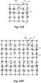
图62显示信息点未配置于区块上方中心的格区的结构。如此,未配置信息点3于预定格区(虚拟格点或参考点),可依据该格区位置定义区块方向。本图中,已知本区块为向上。FIG. 62 shows the structure of the grid area where the information dots are not arranged in the center above the block. In this way, the
此外,图63显示区块方向通过配置信息点3于区块上方中心的虚拟格点来定义的情况。In addition, FIG. 63 shows the situation where the direction of the block is defined by arranging the
图60以多个形状表示信息点欲配置于格区的形状。如图60所示,信息点形状系选自于黑色方形、黑色三角形和黑色圆形,各形状可定义不同的信息。FIG. 60 shows the shapes in which information dots are to be arranged in grid areas in a plurality of shapes. As shown in Figure 60, the shape of the information point is selected from black square, black triangle and black circle, and each shape can define different information.
此外,本图中通过将参考格点中的两点配置于偏离参考格点的四个角隅,可定义区块的形状。本图中,因位在区块左上和右上的参考格点向上偏移,故可辨识此区块为向上。In addition, in this figure, the shape of the block can be defined by arranging two points in the reference grid at four corners deviated from the reference grid. In this figure, because the reference grid points on the upper left and upper right of the block are shifted upward, it can be identified that this block is upward.
图61显示配置于区块中心的格区之虚拟格点的信息点3与其它信息点的形状不同的情况。于本虚拟格点,配置三角形信息点,由于此三角形形状,可辨识此区块为向上。FIG. 61 shows the situation that the shape of the information dot 3 of the virtual grid point arranged in the grid area at the center of the block is different from that of other information dots. At this virtual grid point, triangular information points are arranged, and because of the triangular shape, it can be recognized that this block is upward.
本发明可宽广应用于所举例说明之书籍、相片、卡片游戏、及安全系统等通过光学传感器读取的用途。The present invention can be widely applied to the illustrated books, photos, card games, and security systems, etc., which are read by optical sensors.
附图说明Description of drawings
图1为GRID1中一种点状图样之主视图(1);Fig. 1 is the front view (1) of a dot pattern in GRID1;
图2显示该点状图样之信息点和此处定义数据之一位显示之实例;Figure 2 shows an example of the information dots of the dot pattern and a bit display of the data defined here;
图3A、3B为说明图,显示GRID1关键点,且显示信息点之配置实例;Figures 3A and 3B are explanatory diagrams showing the key points of GRID1 and displaying configuration examples of information points;
图4为视图,显示于GRID1中之信息点之配置实例,且显示该点状图样之信息点和此处定义数据之位显示之实例;Fig. 4 is a view showing an example of the configuration of information points in GRID1, and shows an example of the information points of the dot pattern and the bit display of defined data here;
图5A~C显示GRID1中之信息点及此处定义之数据之位显示之实例;Figures 5A-C show examples of information points in GRID1 and bit displays of data defined here;
图6A~D为视图,显示于GRID1中之点状图样之修改例;6A-D are views showing modified examples of dot patterns in GRID1;
图7为GRID3之点状图样之主视图;Fig. 7 is the front view of the dot pattern of GRID3;
图8为视图,显示于GRID3中信息点之配置实例;Figure 8 is a view showing an example of the configuration of information points in GRID3;
图9A~C为说明图,显示关键点及GRID3之信息点;Figures 9A-C are explanatory diagrams showing key points and information points of GRID3;
图10显示于GRID3之信息点和此处定义之数据之位显示之实例;Figure 10 shows an example of the bit display of information points and data defined here in GRID3;
图11A~F显示于GRID3之信息点3和此处定义之数据之位显示之实例;Figures 11A-F show an example of bit display at
图12A~D为视图,显示于GRID3中之点状图样之修改例;12A-D are views showing modified examples of dot patterns in GRID3;
图13A~C为GRID4之点状图样之主视图;13A-C are the front views of the dot pattern of GRID4;
图14为视图(1),显示GRID4中之信息点之一种定义方法;Fig. 14 is view (1), shows a kind of definition method of the information point in GRID4;
图15为视图(2),显示GRID4中之信息点之一种定义方法;Fig. 15 is view (2), shows a kind of definition method of the information point in GRID4;
图16A~C为视图(3),显示GRID4中之信息点之一种定义方法;Fig. 16A~C is view (3), shows a kind of definition method of the information point in GRID4;
图17A~C为视图(4),显示GRID4中之信息点之一种定义方法;Fig. 17A~C is view (4), shows a kind of definition method of the information point in GRID4;
图18A~C为说明图,显示于GRID4中通过光学读取装置读取信息点之读取顺序;18A-C are explanatory diagrams showing the reading sequence of reading information points by an optical reading device in GRID4;
图19为视图,有关键点配置来替代于GRID4之参考格点位置;Figure 19 is a view, with key point configuration to replace the reference grid position of GRID4;
图20为说明图,显示通过于GRID4中使用区别方法来读取信息点之一种读取方法;FIG. 20 is an explanatory diagram showing a reading method of reading information points by using a distinction method in GRID4;
图21A、B为视图(1),具有排列于GRID1之方向点;Figure 21A and B are views (1), with direction points arranged in GRID1;
图22A、B显示视图(2)之信息点之配置顺序,具有方向点排列于GRID1;Figure 22A and B show the arrangement order of the information points in view (2), with the direction points arranged in GRID1;
图23A、B为视图(1),具有排列于GRID3之方向点;Figure 23A and B are views (1), with direction points arranged in GRID3;
图24为视图(2),具有排列于GRID3之方向点;Figure 24 is view (2) with orientation points arranged in GRID3;
图25A、B为视图(1),显示GRID3之信息点之配置顺序;25A and B are views (1), showing the arrangement order of information points of GRID3;
图26A、B为视图,显示GRID3之方向点之配置顺序;26A and B are views showing the arrangement order of the direction points of GRID3;
图27A、B为视图(2),显示GRID3之信息点之配置顺序;27A and B are views (2), showing the arrangement order of the information points of GRID3;
图28A、B为视图(1),具有排列于GRID4之方向点;Figure 28A and B are views (1), with direction points arranged in GRID4;
图29为视图(1),显示GRID4之信息点之配置顺序;Figure 29 is a view (1), showing the configuration order of the information points of GRID4;
图30为视图(2),显示GRID4之信息点之配置顺序;Figure 30 is a view (2), showing the configuration order of the information points of GRID4;
图31A、B为视图,显示GRID4之方向点之配置顺序;Figure 31A and B are views showing the arrangement order of the direction points of GRID4;
图32为视图(3),显示GRID4之信息点之配置顺序;Figure 32 is a view (3), showing the configuration order of the information points of GRID4;
图33为视图(4),显示GRID4之信息点之配置顺序;Figure 33 is a view (4), showing the configuration order of the information points of GRID4;
图34A、B为说明视图(1)改变如何配置信息点及定义GRID1中之区块方向;Fig. 34A, B is to explain how to change the view (1) to configure information points and define the block direction in GRID1;
图35A、B为说明视图(2)改变如何配置信息点及定义GRID1中之区块方向;Fig. 35A, B is to explain how to change the view (2) to configure information points and define the block direction in GRID1;
图36A、B为说明视图(3)改变如何配置信息点及定义GRID1中之区块方向;Fig. 36A, B are to explain how to change the view (3) to configure information points and define the direction of blocks in GRID1;
图37A、B为说明视图(4)改变如何配置信息点及定义GRID1中之区块方向;Fig. 37A, B is to illustrate how view (4) changes how to configure information points and define the block direction in GRID1;
图38A~C为视图(1),显示当无法定义区块和方向时之一种配置实例;Figure 38A~C is a view (1), showing a configuration example when the blocks and directions cannot be defined;
图39为视图(2),显示当无法定义区块和方向时之一种配置实例;Figure 39 is a view (2), showing an example of a configuration when blocks and directions cannot be defined;
图40A、B为说明视图(1)改变如何配置信息点及定义GRID3中之区块方向;Fig. 40A, B are for explaining view (1) changing how to configure information points and define the block direction in GRID3;
图41A、B为说明视图(2)改变如何配置信息点及定义GRID3中之区块方向;Fig. 41A, B are for explaining view (2) changing how to arrange information points and define the block direction in GRID3;
图42A、B为说明视图(3)改变如何配置信息点及定义GRID3中之区块方向;Fig. 42A, B is to illustrate how view (3) changes how to configure information points and define the block direction in GRID3;
图43A、B为说明视图(4)改变如何配置信息点及定义GRID3中之区块方向;Fig. 43A, B is to illustrate how view (4) changes how to configure information points and define the block direction in GRID3;
图44A、B为说明视图(1)改变如何配置信息点及定义GRID4中之区块方向;Fig. 44A, B is to illustrate how to change the view (1) to configure information points and define the block direction in GRID4;
图45为说明视图(2)改变如何配置信息点及定义GRID4中之区块方向;Fig. 45 is to illustrate how view (2) changes how to configure information points and define the block direction in GRID4;
图46为说明视图(3)改变如何配置信息点及定义GRID4中之区块方向;Fig. 46 illustrates how to change the view (3) to configure information points and define the block direction in GRID4;
图47A~C为说明图,显示根据本实施例,方向点及信息点之判定演绎法则;47A-C are explanatory diagrams showing the deduction rules for determining direction points and information points according to this embodiment;
图48为说明图(1),依据如何配置参考点于具有格子以外之形状之区块中,来定义区块之方向;Figure 48 is an explanatory diagram (1), according to how to configure the reference point in the block with a shape other than the grid, to define the direction of the block;
图49为说明图(2),依据如何配置参考点于具有格子以外之形状之区块中,来定义区块之方向;Figure 49 is an explanatory diagram (2), according to how to configure the reference point in the block with a shape other than the grid, to define the direction of the block;
图50为说明图(1),当区块形状非为矩形区,且部分参考点重合部分参考格点时,依据如何配置参考点,来定义区块方向;Fig. 50 is an explanatory diagram (1). When the shape of the block is not a rectangular area, and part of the reference points coincide with part of the reference grid points, the direction of the block is defined according to how to configure the reference points;
图51为说明图(2),当区块形状非为矩形区,且部分参考点重合部分参考格点时,依据如何配置参考点,来定义区块方向;Fig. 51 is an explanatory diagram (2). When the shape of the block is not a rectangular area, and part of the reference points coincide with part of the reference grid points, the direction of the block is defined according to how to configure the reference points;
图52为说明图(1),于具有参考点配置于区块的四角隅之区块中,改变如何配置信息点,且定义区块之方向;Figure 52 is an explanatory diagram (1), in a block with reference points arranged at the four corners of the block, how to change the arrangement of information points, and define the direction of the block;
图53为说明图(2),于具有参考点配置于区块的四角隅之区块中,改变如何配置信息点,且定义区块之方向;Figure 53 is an explanatory diagram (2), in a block with reference points arranged at the four corners of the block, how to change the arrangement of information points, and define the direction of the block;
图54为说明图(3),于具有参考点配置于区块的四角隅之区块中,改变如何配置信息点,且定义区块之方向;Figure 54 is an explanatory diagram (3), in a block with reference points arranged at the four corners of the block, how to change the arrangement of information points, and define the direction of the block;
图55为说明图(4),于具有参考点配置于区块的四角隅之区块中,改变如何配置信息点,且定义区块之方向;Figure 55 is an explanatory diagram (4), in a block with reference points arranged at the four corners of the block, how to change the arrangement of information points, and define the direction of the block;
图56为说明图,于具有参考点配置于区块的四角隅之该区块中,通过随形部分参考点于格点来定义区块之方向;Fig. 56 is an explanatory diagram, in the block with reference points arranged at the four corners of the block, the direction of the block is defined by the reference point of the conformal part at the grid point;
图57为说明图,于形状系与格子形状不同之区块中,改变参考点大小且定义区块方向;Fig. 57 is an explanatory diagram, in a block whose shape is different from that of a grid, change the size of the reference point and define the direction of the block;
图58为说明图,于形状具有呈格状之区块中,改变参考点大小且定义区块方向;Fig. 58 is an explanatory diagram, in which the size of the reference point is changed and the direction of the block is defined in a block shaped like a grid;
图59为说明图,显示配置于区块中心的信息点尺寸比其它信息点更大,被作为方向点之状态;Fig. 59 is an explanatory diagram showing the state that the information dot arranged in the center of the block is larger than other information dots and is used as a direction point;
图60为说明图,改变信息点形状及定义区块方向;Figure 60 is an explanatory diagram, changing the shape of the information point and defining the direction of the block;
图61为说明图,通过以其它信息点形状,改变配置于区块中心之该信息点形状来定义该区块之方向;Fig. 61 is an explanatory diagram, the direction of the block is defined by changing the shape of the information point arranged in the center of the block with other information point shapes;
图62为说明图,通过未配置信息点于位在区块中心之格区的虚拟格点上,来定义该区块方向;以及FIG. 62 is an explanatory diagram, defining the direction of the block by not disposing information points on the virtual grid points of the grid area located in the center of the block; and
图63为说明图,通过配置信息点于位在区块中心之该格区的该虚拟格点上,来定义该区块方向。FIG. 63 is an explanatory diagram in which the direction of the block is defined by arranging information points on the virtual grid point of the grid area located at the center of the block.
主要元件标记说明Description of main component marking
1...点状图样 3...信息点1...dot
2...关键点 4...参考格点2...
5...中心虚拟格点 28b...下网格线5... Center
6...虚拟格点 28c...中心网格线6...
7、7a-d...参考网格线 34a-c...格区7. 7a-d...reference grid lines 34a-c...grid area
8a、8b...网格线 34a...左下格区8a, 8b...grid lines 34a...lower left grid area
8c...斜向网格线 34b...中心格区8c...Diagonal grid lines 34b...Central grid area
11...虚拟格点 34c...右下格区11...virtual grid point 34c...lower right grid area
12...虚拟参考格点 36a-d...格区12...
13...虚拟格点 381-396...格区13...virtual grid point 381-396... grid area
14...虚拟格点 401-406...线格区14...virtual grid point 401-406...line grid area
21...方向点 411...上中格区21...
21a...方向区 48a-e...参考点21a...
23a-c...区块 48f-h...虚拟参考点23a-c...block 48f-h...virtual reference point
24...中心 4a...参考点24...
28A、28B...横向网格线 58a...参考点28A, 28B...horizontal grid lines 58a...reference point
28a...上网格线28a... Upper grid lines
Claims (16)
Translated fromChinesePriority Applications (1)
| Application Number | Priority Date | Filing Date | Title |
|---|---|---|---|
| CN201210025984.XACN102722267B (en) | 2005-07-01 | 2006-06-30 | Dot pattern |
Applications Claiming Priority (3)
| Application Number | Priority Date | Filing Date | Title |
|---|---|---|---|
| JP194295/2005 | 2005-07-01 | ||
| JP2005194295AJP3771252B1 (en) | 2005-07-01 | 2005-07-01 | Dot pattern |
| PCT/SG2006/000185WO2007004994A1 (en) | 2005-07-01 | 2006-06-30 | Dot pattern |
Related Child Applications (1)
| Application Number | Title | Priority Date | Filing Date |
|---|---|---|---|
| CN201210025984.XADivisionCN102722267B (en) | 2005-07-01 | 2006-06-30 | Dot pattern |
Publications (2)
| Publication Number | Publication Date |
|---|---|
| CN101213564A CN101213564A (en) | 2008-07-02 |
| CN101213564Btrue CN101213564B (en) | 2012-04-25 |
Family
ID=36383733
Family Applications (2)
| Application Number | Title | Priority Date | Filing Date |
|---|---|---|---|
| CN2006800235674AExpired - Fee RelatedCN101213564B (en) | 2005-07-01 | 2006-06-30 | Dot pattern |
| CN201210025984.XAExpired - Fee RelatedCN102722267B (en) | 2005-07-01 | 2006-06-30 | Dot pattern |
Family Applications After (1)
| Application Number | Title | Priority Date | Filing Date |
|---|---|---|---|
| CN201210025984.XAExpired - Fee RelatedCN102722267B (en) | 2005-07-01 | 2006-06-30 | Dot pattern |
Country Status (14)
| Country | Link |
|---|---|
| US (3) | US8430328B2 (en) |
| EP (2) | EP2439677B1 (en) |
| JP (1) | JP3771252B1 (en) |
| KR (1) | KR100935345B1 (en) |
| CN (2) | CN101213564B (en) |
| AU (1) | AU2006266517B2 (en) |
| BR (1) | BRPI0612755B1 (en) |
| CA (1) | CA2613046C (en) |
| IL (1) | IL188225A (en) |
| MX (1) | MX352384B (en) |
| MY (1) | MY164588A (en) |
| RU (1) | RU2439699C2 (en) |
| TW (3) | TWI618000B (en) |
| WO (1) | WO2007004994A1 (en) |
Families Citing this family (52)
| Publication number | Priority date | Publication date | Assignee | Title |
|---|---|---|---|---|
| MXPA05003310A (en) | 2002-09-26 | 2005-10-18 | Yoshida Kenji | Information reproduction/i/o method using dot pattern, information reproduction device, mobile information i/o device, and electronic toy. |
| US8237983B2 (en)* | 2004-12-28 | 2012-08-07 | Kenji Yoshida | Information input output method using dot pattern |
| CA2606135C (en) | 2005-04-28 | 2015-06-30 | Kenji Yoshida | Information input/output method using dot pattern |
| JP3771252B1 (en)* | 2005-07-01 | 2006-04-26 | 健治 吉田 | Dot pattern |
| JP3830956B1 (en)* | 2005-09-14 | 2006-10-11 | 健治 吉田 | Information output device |
| EP1983412A4 (en)* | 2006-01-31 | 2011-07-20 | Kenji Yoshida | Image processing method |
| TWI370413B (en) | 2006-04-14 | 2012-08-11 | Sonix Technology Co Ltd | Graphical indicator |
| US7445160B2 (en)* | 2006-06-14 | 2008-11-04 | Hewlett-Packard Development Company, L.P. | Position location using error correction |
| US20080252916A1 (en)* | 2007-04-13 | 2008-10-16 | Etoms Electronics Corp. | Information reproduction method and device using dot pattern and dot pattern thereof |
| CN101849243B (en)* | 2007-10-30 | 2014-05-28 | 吉田健治 | Code pattern |
| AU2007254595B2 (en)* | 2007-12-20 | 2011-04-07 | Canon Kabushiki Kaisha | Constellation detection |
| DE102008017168A1 (en)* | 2008-04-02 | 2009-10-08 | Crossmedia Solution Gmbh & Co. Kg | Method for storing and reading data |
| KR100968255B1 (en) | 2008-07-01 | 2010-07-06 | 이병진 | Contact card recognition system and recognition method using touch screen |
| EP2312375A4 (en) | 2008-07-15 | 2012-10-10 | Kenji Yoshida | Naked eye three-dimensional video image display system, naked eye three-dimensional video image display device, amusement game machine and parallax barrier sheet |
| TWI397013B (en)* | 2008-09-26 | 2013-05-21 | Elan Microelectronics Corp | The dot code pattern and the dot code group pattern and the image processing circuit of the density coding type |
| CN101727596B (en)* | 2008-10-13 | 2013-09-18 | 义隆电子股份有限公司 | Dot code pattern and image processing device for processing dot code pattern |
| CN101727595B (en)* | 2008-10-13 | 2012-09-26 | 义隆电子股份有限公司 | Dot code pattern and dot code group pattern and its image processing circuit |
| US9010640B2 (en) | 2009-07-13 | 2015-04-21 | Kenji Yoshida | Stream dot pattern, method of forming stream dot pattern, information input/output method using stream dot pattern, and dot pattern |
| US9749607B2 (en) | 2009-07-16 | 2017-08-29 | Digimarc Corporation | Coordinated illumination and image signal capture for enhanced signal detection |
| JP2011053854A (en)* | 2009-09-01 | 2011-03-17 | Hong-Teng Lv | Coding method of two-dimensional optical recognition code and print product using the method |
| US8218004B2 (en)* | 2009-10-22 | 2012-07-10 | Cycling & Health Tech Industry R&D Center | Displacement sensing system |
| KR100991878B1 (en)* | 2009-10-22 | 2010-11-04 | 장효선 | Code decoding method being indicated on printed object |
| JP5604761B2 (en) | 2009-11-11 | 2014-10-15 | 健治 吉田 | Print medium, information processing method, information processing apparatus |
| JP5277403B2 (en)* | 2010-01-06 | 2013-08-28 | 健治 吉田 | Curved body for information input, map for information input, drawing for information input |
| TWI439943B (en)* | 2010-04-27 | 2014-06-01 | Shou Te Wei | Encoding structure for dot pattern, its decoding method and electronic device |
| US9576230B2 (en)* | 2010-07-06 | 2017-02-21 | Marcelo Amaral Rezende | Dot code pattern for absolute position and other information using an optical pen, process of printing the dot code, process of reading the dot code |
| JP5315512B2 (en) | 2010-12-09 | 2013-10-16 | 健治 吉田 | Machine readable dot pattern |
| WO2013027234A1 (en)* | 2011-08-22 | 2013-02-28 | Zak株式会社 | Satellite dot type two-dimensional code and method for reading same |
| CN103390183B (en)* | 2012-05-09 | 2019-07-19 | 顾泽苍 | A kind of generation method of the anti-counterfeiting codes suitable for handset identity |
| JP5344328B1 (en)* | 2012-10-01 | 2013-11-20 | 健治 吉田 | Dot pattern, dot pattern forming medium, dot pattern image data generating program, dot pattern forming device, optical device, optical reader, information input / output device, dot pattern reader |
| KR102076233B1 (en) | 2012-12-05 | 2020-02-11 | 가부시키가이샤 아이피솔루션즈 | Facility-management-system control interface |
| TWI489352B (en)* | 2013-08-13 | 2015-06-21 | Wistron Corp | Optical touch positioning method, system and optical touch positioner |
| US9635378B2 (en) | 2015-03-20 | 2017-04-25 | Digimarc Corporation | Sparse modulation for robust signaling and synchronization |
| US10424038B2 (en) | 2015-03-20 | 2019-09-24 | Digimarc Corporation | Signal encoding outside of guard band region surrounding text characters, including varying encoding strength |
| TWI492167B (en) | 2014-06-05 | 2015-07-11 | Sonix Technology Co Ltd | Graphical indicator |
| EP3045214A1 (en) | 2015-01-14 | 2016-07-20 | Cartamundi Turnhout N.V. | Board game with pattern recognition |
| US10783601B1 (en) | 2015-03-20 | 2020-09-22 | Digimarc Corporation | Digital watermarking and signal encoding with activable compositions |
| WO2016153936A1 (en) | 2015-03-20 | 2016-09-29 | Digimarc Corporation | Digital watermarking and data hiding with narrow-band absorption materials |
| ES2724010T3 (en)* | 2015-04-30 | 2019-09-05 | Nestle Sa | Code and system container for preparing a beverage or food |
| WO2017007483A1 (en)* | 2015-07-09 | 2017-01-12 | Hewlett-Packard Development Company, L.P. | Multi-dimensional cyclic symbols |
| TWI545504B (en) | 2015-08-31 | 2016-08-11 | 原相科技股份有限公司 | Decoding method using patterns and system thereof |
| US9600700B1 (en) | 2015-08-31 | 2017-03-21 | Pixart Imaging Inc. | Portable electronic device and operation method thereof |
| US9805239B2 (en) | 2015-08-31 | 2017-10-31 | Pixart Imagine Inc. | QR code detecting device and operation method thereof |
| CN109359657B (en) | 2015-10-19 | 2022-11-25 | 松翰科技股份有限公司 | Index structure |
| US10896307B2 (en) | 2017-11-07 | 2021-01-19 | Digimarc Corporation | Generating and reading optical codes with variable density to adapt for visual quality and reliability |
| US11062108B2 (en) | 2017-11-07 | 2021-07-13 | Digimarc Corporation | Generating and reading optical codes with variable density to adapt for visual quality and reliability |
| US10872392B2 (en) | 2017-11-07 | 2020-12-22 | Digimarc Corporation | Generating artistic designs encoded with robust, machine-readable data |
| KR102066391B1 (en)* | 2017-11-16 | 2020-01-15 | 상명대학교산학협력단 | Data embedding appratus for multidimensional symbology system based on 3-dimension and data embedding method for the symbology system |
| KR102104027B1 (en)* | 2018-08-30 | 2020-04-23 | 선문대학교 산학협력단 | Mesh structure indicating information and touch device having sensing electrode made of the mesh structure |
| US20220398769A1 (en)* | 2019-10-31 | 2022-12-15 | Hewlett-Packard Development Company, L.P. | Recovering alignment grids |
| KR102450872B1 (en)* | 2020-10-05 | 2022-10-05 | 에르미 주식회사 | Dot pattern and method for recognizing dot pattern |
| US12361248B2 (en) | 2023-05-19 | 2025-07-15 | Aires Investment Holdings Private Limited | Two-dimensional code and method and system for generating and reading thereof |
Citations (2)
| Publication number | Priority date | Publication date | Assignee | Title |
|---|---|---|---|---|
| US5896403A (en)* | 1992-09-28 | 1999-04-20 | Olympus Optical Co., Ltd. | Dot code and information recording/reproducing system for recording/reproducing the same |
| US6964373B2 (en)* | 2001-03-06 | 2005-11-15 | Olympus Optical Co., Ltd. | Recording medium and coded image reader apparatus |
Family Cites Families (91)
| Publication number | Priority date | Publication date | Assignee | Title |
|---|---|---|---|---|
| US4263504A (en) | 1979-08-01 | 1981-04-21 | Ncr Corporation | High density matrix code |
| US4604065A (en) | 1982-10-25 | 1986-08-05 | Price/Stern/Sloan Publishers, Inc. | Teaching or amusement apparatus |
| JPS6165213A (en) | 1984-09-06 | 1986-04-03 | Canon Inc | Optical system for autofocus |
| US4627819A (en) | 1985-01-23 | 1986-12-09 | Price/Stern/Sloan Publishers, Inc. | Teaching or amusement apparatus |
| US4924078A (en) | 1987-11-25 | 1990-05-08 | Sant Anselmo Carl | Identification symbol, system and method |
| US5124536A (en) | 1988-05-05 | 1992-06-23 | International Data Matrix, Inc. | Dynamically variable machine readable binary code and method for reading and producing thereof |
| US4939354A (en) | 1988-05-05 | 1990-07-03 | Datacode International, Inc. | Dynamically variable machine readable binary code and method for reading and producing thereof |
| US5591957A (en) | 1988-08-12 | 1997-01-07 | Casio Computer Co., Ltd. | Apparatus for reading mesh pattern image data having bars along upper and lower sides of mesh pattern and a boundary line between horizontally adjacent dark and light area of mesh pattern |
| US5042079A (en) | 1988-08-12 | 1991-08-20 | Casio Computer Co., Ltd. | Method of recording/reproducing data of mesh pattern, and apparatus therefor |
| US5051736A (en) | 1989-06-28 | 1991-09-24 | International Business Machines Corporation | Optical stylus and passive digitizing tablet data input system |
| US5128528A (en)* | 1990-10-15 | 1992-07-07 | Dittler Brothers, Inc. | Matrix encoding devices and methods |
| FR2684214B1 (en) | 1991-11-22 | 1997-04-04 | Sepro Robotique | INDEXING CARD FOR GEOGRAPHIC INFORMATION SYSTEM AND SYSTEM INCLUDING APPLICATION. |
| US5852434A (en) | 1992-04-03 | 1998-12-22 | Sekendur; Oral F. | Absolute optical position determination |
| JPH10187907A (en) | 1992-09-28 | 1998-07-21 | Olympus Optical Co Ltd | Dot code |
| US5416312A (en) | 1992-11-20 | 1995-05-16 | Cherloc | Document bearing an image or a text and provided with an indexing frame, and associated document analysis system |
| RU2126598C1 (en) | 1993-11-16 | 1999-02-20 | Кузнецов Юрий Вениаминович | Method and device for adaptive rendering of half-tone images |
| JP3277052B2 (en) | 1993-11-19 | 2002-04-22 | シャープ株式会社 | Coordinate input device and coordinate input method |
| JPH07178257A (en) | 1993-12-24 | 1995-07-18 | Casio Comput Co Ltd | Audio output device |
| JPH07296387A (en) | 1994-04-22 | 1995-11-10 | Olympus Optical Co Ltd | Information recording medium |
| JPH0837567A (en) | 1994-07-26 | 1996-02-06 | Olympus Optical Co Ltd | Information recording medium and information reproducing device |
| JP2912831B2 (en) | 1994-10-05 | 1999-06-28 | オリンパス光学工業株式会社 | Information recording medium and information reproducing apparatus |
| JP3639328B2 (en)* | 1994-10-14 | 2005-04-20 | オリンパス株式会社 | Information recording medium, two-dimensional code, information reproducing system, and information reproducing method |
| US5661506A (en) | 1994-11-10 | 1997-08-26 | Sia Technology Corporation | Pen and paper information recording system using an imaging pen |
| JP2952170B2 (en) | 1994-12-16 | 1999-09-20 | オリンパス光学工業株式会社 | Information reproduction system |
| TW331000B (en)* | 1994-12-28 | 1998-05-01 | Eten Information System Co Ltd | Method for determining crossing points of two overlapping figures |
| JP3523710B2 (en) | 1995-04-04 | 2004-04-26 | オリンパス株式会社 | Information reproduction system, recording medium, recording device, and recording method |
| GB9507098D0 (en) | 1995-04-06 | 1995-05-31 | Rolls Royce Plc | Process and apparatus for reading a dot matrix code marking of an article |
| JPH0944591A (en) | 1995-08-03 | 1997-02-14 | Olympus Optical Co Ltd | Code sheet and information reproducing device |
| JPH09114951A (en) | 1995-10-23 | 1997-05-02 | Olympus Optical Co Ltd | Information recording medium |
| JPH09185488A (en) | 1995-12-27 | 1997-07-15 | Tetsuya Fuchiguchi | Multimedia doll system |
| JP3956419B2 (en) | 1997-03-06 | 2007-08-08 | 凸版印刷株式会社 | ID card creation method, ID card and ID card information reading method |
| JPH10326331A (en)* | 1997-03-24 | 1998-12-08 | Olympus Optical Co Ltd | Recording medium with dot code, and code reader |
| JPH10326323A (en) | 1997-03-24 | 1998-12-08 | Olympus Optical Co Ltd | Code pattern image recording device |
| US6012961A (en) | 1997-05-14 | 2000-01-11 | Design Lab, Llc | Electronic toy including a reprogrammable data storage device |
| JPH10320497A (en) | 1997-05-16 | 1998-12-04 | Olympus Optical Co Ltd | Code reading and recording device |
| JP3953144B2 (en) | 1997-07-16 | 2007-08-08 | オリンパス株式会社 | Code image quality inspection system |
| EP0921675B1 (en) | 1997-12-03 | 2006-07-05 | Kabushiki Kaisha Toshiba | Method of processing image information and method of preventing forgery of certificates or the like |
| JP3959817B2 (en) | 1998-01-07 | 2007-08-15 | 富士ゼロックス株式会社 | Image forming apparatus |
| JPH11219405A (en) | 1998-02-02 | 1999-08-10 | Olympus Optical Co Ltd | Information reproducing system |
| WO1999050736A1 (en) | 1998-04-01 | 1999-10-07 | Xerox Corporation | Paper indexing of recordings |
| JP3458737B2 (en) | 1998-11-27 | 2003-10-20 | 株式会社デンソー | Reading method of two-dimensional code and recording medium |
| JP2000285225A (en) | 1999-03-30 | 2000-10-13 | Kiyoyuki Horii | Method for processing image by computer |
| RU2166207C2 (en) | 1999-04-08 | 2001-04-27 | Закрытое акционерное общество "Аби Программное обеспечение" | Method for using auxiliary data arrays in conversion and/or verification of character-expressed computer codes and respective subpictures |
| GB2349836A (en) | 1999-04-23 | 2000-11-15 | Tri State | Talking doll with bar-code optical reader |
| JP2000325668A (en) | 1999-05-14 | 2000-11-28 | T Shot:Kk | Reactive talking toy system |
| AUPQ363299A0 (en) | 1999-10-25 | 1999-11-18 | Silverbrook Research Pty Ltd | Paper based information inter face |
| US6728000B1 (en) | 1999-05-25 | 2004-04-27 | Silverbrook Research Pty Ltd | Method and system for printing a document |
| US6830196B1 (en) | 1999-05-25 | 2004-12-14 | Silverbrook Research Pty Ltd | Identity-coded surface region |
| JP4785310B2 (en) | 1999-05-28 | 2011-10-05 | アノト アクティエボラーク | Products used to record information |
| JP3764100B2 (en) | 1999-05-28 | 2006-04-05 | アノト アイ ピー リック エイチ ビー | Calendar book |
| EP1188142A1 (en) | 1999-05-28 | 2002-03-20 | Anoto AB | Recording of information |
| SE516522C2 (en) | 1999-05-28 | 2002-01-22 | Anoto Ab | Position determining product for digitization of drawings or handwritten information, obtains displacement between symbol strings along symbol rows when symbol strings are repeated on symbol rows |
| JP2001052104A (en) | 1999-08-05 | 2001-02-23 | Olympus Optical Co Ltd | Data recording method, data reproducing method and data recording medium |
| SE0000939L (en) | 2000-02-18 | 2001-08-19 | Anoto Ab | Inenhetsarrangemang |
| US6533182B1 (en)* | 1999-09-21 | 2003-03-18 | Omron Corporation | Two-dimensional dot code and reader thereof |
| SE517445C2 (en) | 1999-10-01 | 2002-06-04 | Anoto Ab | Position determination on a surface provided with a position coding pattern |
| MXPA02006340A (en) | 1999-12-23 | 2002-12-13 | Anoto Ab | General information management system. |
| US6244764B1 (en) | 2000-01-21 | 2001-06-12 | Robotic Vision Systems, Inc. | Method for data matrix print quality verification |
| WO2001059643A1 (en) | 2000-02-10 | 2001-08-16 | Sony Corporation | Automatic device, information providing device, robot device, and transaction method |
| US7050653B2 (en) | 2000-04-05 | 2006-05-23 | Anoto Ab | Identification of virtual raster pattern |
| US6586688B2 (en) | 2000-04-05 | 2003-07-01 | Anoto Ab | Information-related devices and methods |
| JP2001287330A (en) | 2000-04-10 | 2001-10-16 | Olympus Optical Co Ltd | Method and apparatus for forming image data of optically readable dots and recording medium |
| JP2001318926A (en) | 2000-05-11 | 2001-11-16 | Yazaki Corp | Information management device and information management system using the device |
| JP2002041199A (en) | 2000-05-15 | 2002-02-08 | Pasukaru:Kk | Operation processing method for computer device using shortcut symbol, and shortcut processing system |
| JP2001334012A (en) | 2000-05-29 | 2001-12-04 | Creatures Inc | Game system using game card, game card used therefor, and game information storage medium used therefor |
| JP3837999B2 (en) | 2000-06-05 | 2006-10-25 | 富士ゼロックス株式会社 | Image generation method and image generation apparatus |
| JP2002002024A (en) | 2000-06-26 | 2002-01-08 | Olympus Optical Co Ltd | Method and apparatus for printing code and recording medium |
| AU2001284468A1 (en) | 2000-09-12 | 2002-03-26 | Omron Corporation | Dot code and dot code reader |
| JP4567860B2 (en) | 2000-09-12 | 2010-10-20 | 任天堂株式会社 | Code reader, recording medium, electronic device, data transmission / reception system, and data transmission / reception method |
| JP2002205291A (en) | 2000-10-23 | 2002-07-23 | Sony Corp | Leg type robot and movement control method for leg type robot, as well as recording medium |
| JP2002149331A (en) | 2000-11-15 | 2002-05-24 | Canon Inc | Coordinate plate, coordinate input device, coordinate input / output device |
| US6633008B2 (en) | 2001-02-27 | 2003-10-14 | Weigh-Tronix, Inc. | Electronic force sensing shock resistant load cell |
| US7649637B2 (en) | 2001-04-05 | 2010-01-19 | Anoto Ab | Method for printing a global position-coding pattern |
| US6732927B2 (en) | 2001-06-26 | 2004-05-11 | Anoto Ab | Method and device for data decoding |
| SE520682C2 (en) | 2001-12-06 | 2003-08-12 | Anoto Ab | Reconstruction of a virtual screen |
| TWI235926B (en) | 2002-01-11 | 2005-07-11 | Sonix Technology Co Ltd | A method for producing indicators and processing system, coordinate positioning system and electronic book system utilizing the indicators |
| MXPA05003310A (en)* | 2002-09-26 | 2005-10-18 | Yoshida Kenji | Information reproduction/i/o method using dot pattern, information reproduction device, mobile information i/o device, and electronic toy. |
| SE0203853D0 (en) | 2002-12-23 | 2002-12-23 | Anoto Ab | Data code |
| CN100361144C (en) | 2003-03-17 | 2008-01-09 | 吉田健治 | Information input/output method using dot pattern |
| JP3902163B2 (en) | 2003-07-11 | 2007-04-04 | 大日本印刷株式会社 | Related form determination system, electronic pen and program |
| JP4200106B2 (en) | 2003-07-15 | 2008-12-24 | 株式会社リコー | Image processing apparatus, image processing method, computer program, and storage medium for storing computer program |
| AU2003292817A1 (en) | 2003-12-25 | 2005-07-21 | Kenji Yoshida | Method for inputting/outputting information using dot pattern |
| US8237983B2 (en) | 2004-12-28 | 2012-08-07 | Kenji Yoshida | Information input output method using dot pattern |
| JPWO2006112021A1 (en) | 2005-04-15 | 2008-11-27 | 吉田 健治 | Information input / output method using dot pattern |
| CA2606135C (en) | 2005-04-28 | 2015-06-30 | Kenji Yoshida | Information input/output method using dot pattern |
| JP3771252B1 (en) | 2005-07-01 | 2006-04-26 | 健治 吉田 | Dot pattern |
| JP4810918B2 (en) | 2005-08-01 | 2011-11-09 | 富士ゼロックス株式会社 | Code pattern image generating apparatus and method, code pattern image reading apparatus and method, and code pattern image medium |
| AU2006252254B2 (en) | 2006-12-22 | 2009-03-05 | Canon Kabushiki Kaisha | Multiple barcode detection |
| AU2006252239B2 (en) | 2006-12-22 | 2010-04-01 | Canon Kabushiki Kaisha | Barcode pattern |
| US20080252916A1 (en) | 2007-04-13 | 2008-10-16 | Etoms Electronics Corp. | Information reproduction method and device using dot pattern and dot pattern thereof |
| TWI391862B (en)* | 2008-06-06 | 2013-04-01 | Elan Microelectronics Corp | A two-dimensional dot code, a decoding apparatus, and a method thereof |
- 2005
- 2005-07-01JPJP2005194295Apatent/JP3771252B1/ennot_activeExpired - Lifetime
- 2006
- 2006-06-29TWTW105117035Apatent/TWI618000B/ennot_activeIP Right Cessation
- 2006-06-29TWTW95123589Apatent/TWI446279B/ennot_activeIP Right Cessation
- 2006-06-29TWTW103119047Apatent/TWI550528B/ennot_activeIP Right Cessation
- 2006-06-30MYMYPI20063148Apatent/MY164588A/enunknown
- 2006-06-30MXMX2007016474Apatent/MX352384B/enactiveIP Right Grant
- 2006-06-30EPEP11175120.2Apatent/EP2439677B1/ennot_activeNot-in-force
- 2006-06-30KRKR1020077024724Apatent/KR100935345B1/ennot_activeExpired - Fee Related
- 2006-06-30CNCN2006800235674Apatent/CN101213564B/ennot_activeExpired - Fee Related
- 2006-06-30RURU2008102706Apatent/RU2439699C2/ennot_activeIP Right Cessation
- 2006-06-30WOPCT/SG2006/000185patent/WO2007004994A1/enactiveApplication Filing
- 2006-06-30CNCN201210025984.XApatent/CN102722267B/ennot_activeExpired - Fee Related
- 2006-06-30BRBRPI0612755-0Apatent/BRPI0612755B1/ennot_activeIP Right Cessation
- 2006-06-30USUS11/993,527patent/US8430328B2/ennot_activeExpired - Fee Related
- 2006-06-30EPEP06748126.7Apatent/EP1899900B1/ennot_activeRevoked
- 2006-06-30CACA2613046Apatent/CA2613046C/ennot_activeExpired - Fee Related
- 2006-06-30AUAU2006266517Apatent/AU2006266517B2/ennot_activeCeased
- 2007
- 2007-12-18ILIL188225Apatent/IL188225A/ennot_activeIP Right Cessation
- 2013
- 2013-04-29USUS13/872,555patent/US9400951B2/ennot_activeExpired - Fee Related
- 2016
- 2016-07-25USUS15/218,841patent/US20160335528A1/ennot_activeAbandoned
Patent Citations (2)
| Publication number | Priority date | Publication date | Assignee | Title |
|---|---|---|---|---|
| US5896403A (en)* | 1992-09-28 | 1999-04-20 | Olympus Optical Co., Ltd. | Dot code and information recording/reproducing system for recording/reproducing the same |
| US6964373B2 (en)* | 2001-03-06 | 2005-11-15 | Olympus Optical Co., Ltd. | Recording medium and coded image reader apparatus |
Also Published As
Similar Documents
| Publication | Publication Date | Title |
|---|---|---|
| CN101213564B (en) | Dot pattern | |
| AU2005331401B2 (en) | Information input/output method using dot pattern | |
| US7143952B2 (en) | Apparatus and methods relating to image coding | |
| JP4336837B2 (en) | Dot pattern | |
| CN100552694C (en) | Global Localization Method via Fast Image Matching | |
| JP4142683B2 (en) | Dot pattern | |
| HK1176418B (en) | Dot pattern | |
| HK1176418A (en) | Dot pattern | |
| JP3858051B6 (en) | Information input / output method using dot pattern | |
| KR100904171B1 (en) | A product having a code pattern for recognizing an object on the surface and a method of forming the code pattern for recognizing the object | |
| AU2016200254A1 (en) | Dot pattern | |
| AU2012204140A1 (en) | Dot pattern | |
| CN101872411A (en) | Encoding method, decoding method, and encoding and decoding method of microcode array | |
| CN102622573B (en) | Decoding Method of Tiny Code Array | |
| AU2016200846A1 (en) | Printed Material Printed with a Dot Pattern |
Legal Events
| Date | Code | Title | Description |
|---|---|---|---|
| C06 | Publication | ||
| PB01 | Publication | ||
| C10 | Entry into substantive examination | ||
| SE01 | Entry into force of request for substantive examination | ||
| C14 | Grant of patent or utility model | ||
| GR01 | Patent grant | ||
| ASS | Succession or assignment of patent right | Owner name:KENJI YOSHIDA Free format text:FORMER OWNER: GRID IP PTE LTD. Effective date:20120703 | |
| C41 | Transfer of patent application or patent right or utility model | ||
| TR01 | Transfer of patent right | Effective date of registration:20120703 Address after:Tokyo, Japan, Japan Patentee after:Yoshida Kenji Address before:Singapore Singapore Patentee before:Glide IP PTE Limited | |
| C41 | Transfer of patent application or patent right or utility model | ||
| TR01 | Transfer of patent right | Effective date of registration:20160930 Address after:Japan Tokyo paper Ishikawa Beijing yidingmu 9 No. 14-2302 Patentee after:IP Solutions Inc. Address before:Tokyo, Japan, Japan Patentee before:Yoshida Kenji | |
| CF01 | Termination of patent right due to non-payment of annual fee | Granted publication date:20120425 Termination date:20190630 | |
| CF01 | Termination of patent right due to non-payment of annual fee |