CN101209667A - hybrid power output - Google Patents
hybrid power outputDownload PDFInfo
- Publication number
- CN101209667A CN101209667ACNA2006101577276ACN200610157727ACN101209667ACN 101209667 ACN101209667 ACN 101209667ACN A2006101577276 ACNA2006101577276 ACN A2006101577276ACN 200610157727 ACN200610157727 ACN 200610157727ACN 101209667 ACN101209667 ACN 101209667A
- Authority
- CN
- China
- Prior art keywords
- motor
- motor generator
- generator
- clutch
- power
- Prior art date
- Legal status (The legal status is an assumption and is not a legal conclusion. Google has not performed a legal analysis and makes no representation as to the accuracy of the status listed.)
- Pending
Links
Images


Classifications
- B—PERFORMING OPERATIONS; TRANSPORTING
- B60—VEHICLES IN GENERAL
- B60K—ARRANGEMENT OR MOUNTING OF PROPULSION UNITS OR OF TRANSMISSIONS IN VEHICLES; ARRANGEMENT OR MOUNTING OF PLURAL DIVERSE PRIME-MOVERS IN VEHICLES; AUXILIARY DRIVES FOR VEHICLES; INSTRUMENTATION OR DASHBOARDS FOR VEHICLES; ARRANGEMENTS IN CONNECTION WITH COOLING, AIR INTAKE, GAS EXHAUST OR FUEL SUPPLY OF PROPULSION UNITS IN VEHICLES
- B60K6/00—Arrangement or mounting of plural diverse prime-movers for mutual or common propulsion, e.g. hybrid propulsion systems comprising electric motors and internal combustion engines
- B60K6/20—Arrangement or mounting of plural diverse prime-movers for mutual or common propulsion, e.g. hybrid propulsion systems comprising electric motors and internal combustion engines the prime-movers consisting of electric motors and internal combustion engines, e.g. HEVs
- B60K6/22—Arrangement or mounting of plural diverse prime-movers for mutual or common propulsion, e.g. hybrid propulsion systems comprising electric motors and internal combustion engines the prime-movers consisting of electric motors and internal combustion engines, e.g. HEVs characterised by apparatus, components or means specially adapted for HEVs
- B60K6/38—Arrangement or mounting of plural diverse prime-movers for mutual or common propulsion, e.g. hybrid propulsion systems comprising electric motors and internal combustion engines the prime-movers consisting of electric motors and internal combustion engines, e.g. HEVs characterised by apparatus, components or means specially adapted for HEVs characterised by the driveline clutches
- B60K6/387—Actuated clutches, i.e. clutches engaged or disengaged by electric, hydraulic or mechanical actuating means
- B—PERFORMING OPERATIONS; TRANSPORTING
- B60—VEHICLES IN GENERAL
- B60K—ARRANGEMENT OR MOUNTING OF PROPULSION UNITS OR OF TRANSMISSIONS IN VEHICLES; ARRANGEMENT OR MOUNTING OF PLURAL DIVERSE PRIME-MOVERS IN VEHICLES; AUXILIARY DRIVES FOR VEHICLES; INSTRUMENTATION OR DASHBOARDS FOR VEHICLES; ARRANGEMENTS IN CONNECTION WITH COOLING, AIR INTAKE, GAS EXHAUST OR FUEL SUPPLY OF PROPULSION UNITS IN VEHICLES
- B60K6/00—Arrangement or mounting of plural diverse prime-movers for mutual or common propulsion, e.g. hybrid propulsion systems comprising electric motors and internal combustion engines
- B60K6/20—Arrangement or mounting of plural diverse prime-movers for mutual or common propulsion, e.g. hybrid propulsion systems comprising electric motors and internal combustion engines the prime-movers consisting of electric motors and internal combustion engines, e.g. HEVs
- B60K6/22—Arrangement or mounting of plural diverse prime-movers for mutual or common propulsion, e.g. hybrid propulsion systems comprising electric motors and internal combustion engines the prime-movers consisting of electric motors and internal combustion engines, e.g. HEVs characterised by apparatus, components or means specially adapted for HEVs
- B60K6/40—Arrangement or mounting of plural diverse prime-movers for mutual or common propulsion, e.g. hybrid propulsion systems comprising electric motors and internal combustion engines the prime-movers consisting of electric motors and internal combustion engines, e.g. HEVs characterised by apparatus, components or means specially adapted for HEVs characterised by the assembly or relative disposition of components
- B—PERFORMING OPERATIONS; TRANSPORTING
- B60—VEHICLES IN GENERAL
- B60K—ARRANGEMENT OR MOUNTING OF PROPULSION UNITS OR OF TRANSMISSIONS IN VEHICLES; ARRANGEMENT OR MOUNTING OF PLURAL DIVERSE PRIME-MOVERS IN VEHICLES; AUXILIARY DRIVES FOR VEHICLES; INSTRUMENTATION OR DASHBOARDS FOR VEHICLES; ARRANGEMENTS IN CONNECTION WITH COOLING, AIR INTAKE, GAS EXHAUST OR FUEL SUPPLY OF PROPULSION UNITS IN VEHICLES
- B60K6/00—Arrangement or mounting of plural diverse prime-movers for mutual or common propulsion, e.g. hybrid propulsion systems comprising electric motors and internal combustion engines
- B60K6/20—Arrangement or mounting of plural diverse prime-movers for mutual or common propulsion, e.g. hybrid propulsion systems comprising electric motors and internal combustion engines the prime-movers consisting of electric motors and internal combustion engines, e.g. HEVs
- B60K6/42—Arrangement or mounting of plural diverse prime-movers for mutual or common propulsion, e.g. hybrid propulsion systems comprising electric motors and internal combustion engines the prime-movers consisting of electric motors and internal combustion engines, e.g. HEVs characterised by the architecture of the hybrid electric vehicle
- B60K6/44—Series-parallel type
- B60K6/442—Series-parallel switching type
- B—PERFORMING OPERATIONS; TRANSPORTING
- B60—VEHICLES IN GENERAL
- B60L—PROPULSION OF ELECTRICALLY-PROPELLED VEHICLES; SUPPLYING ELECTRIC POWER FOR AUXILIARY EQUIPMENT OF ELECTRICALLY-PROPELLED VEHICLES; ELECTRODYNAMIC BRAKE SYSTEMS FOR VEHICLES IN GENERAL; MAGNETIC SUSPENSION OR LEVITATION FOR VEHICLES; MONITORING OPERATING VARIABLES OF ELECTRICALLY-PROPELLED VEHICLES; ELECTRIC SAFETY DEVICES FOR ELECTRICALLY-PROPELLED VEHICLES
- B60L15/00—Methods, circuits, or devices for controlling the traction-motor speed of electrically-propelled vehicles
- B60L15/20—Methods, circuits, or devices for controlling the traction-motor speed of electrically-propelled vehicles for control of the vehicle or its driving motor to achieve a desired performance, e.g. speed, torque, programmed variation of speed
- B60L15/2045—Methods, circuits, or devices for controlling the traction-motor speed of electrically-propelled vehicles for control of the vehicle or its driving motor to achieve a desired performance, e.g. speed, torque, programmed variation of speed for optimising the use of energy
- B—PERFORMING OPERATIONS; TRANSPORTING
- B60—VEHICLES IN GENERAL
- B60L—PROPULSION OF ELECTRICALLY-PROPELLED VEHICLES; SUPPLYING ELECTRIC POWER FOR AUXILIARY EQUIPMENT OF ELECTRICALLY-PROPELLED VEHICLES; ELECTRODYNAMIC BRAKE SYSTEMS FOR VEHICLES IN GENERAL; MAGNETIC SUSPENSION OR LEVITATION FOR VEHICLES; MONITORING OPERATING VARIABLES OF ELECTRICALLY-PROPELLED VEHICLES; ELECTRIC SAFETY DEVICES FOR ELECTRICALLY-PROPELLED VEHICLES
- B60L3/00—Electric devices on electrically-propelled vehicles for safety purposes; Monitoring operating variables, e.g. speed, deceleration or energy consumption
- B60L3/0023—Detecting, eliminating, remedying or compensating for drive train abnormalities, e.g. failures within the drive train
- B60L3/0061—Detecting, eliminating, remedying or compensating for drive train abnormalities, e.g. failures within the drive train relating to electrical machines
- B—PERFORMING OPERATIONS; TRANSPORTING
- B60—VEHICLES IN GENERAL
- B60L—PROPULSION OF ELECTRICALLY-PROPELLED VEHICLES; SUPPLYING ELECTRIC POWER FOR AUXILIARY EQUIPMENT OF ELECTRICALLY-PROPELLED VEHICLES; ELECTRODYNAMIC BRAKE SYSTEMS FOR VEHICLES IN GENERAL; MAGNETIC SUSPENSION OR LEVITATION FOR VEHICLES; MONITORING OPERATING VARIABLES OF ELECTRICALLY-PROPELLED VEHICLES; ELECTRIC SAFETY DEVICES FOR ELECTRICALLY-PROPELLED VEHICLES
- B60L50/00—Electric propulsion with power supplied within the vehicle
- B60L50/50—Electric propulsion with power supplied within the vehicle using propulsion power supplied by batteries or fuel cells
- B60L50/60—Electric propulsion with power supplied within the vehicle using propulsion power supplied by batteries or fuel cells using power supplied by batteries
- B60L50/61—Electric propulsion with power supplied within the vehicle using propulsion power supplied by batteries or fuel cells using power supplied by batteries by batteries charged by engine-driven generators, e.g. series hybrid electric vehicles
- B—PERFORMING OPERATIONS; TRANSPORTING
- B60—VEHICLES IN GENERAL
- B60L—PROPULSION OF ELECTRICALLY-PROPELLED VEHICLES; SUPPLYING ELECTRIC POWER FOR AUXILIARY EQUIPMENT OF ELECTRICALLY-PROPELLED VEHICLES; ELECTRODYNAMIC BRAKE SYSTEMS FOR VEHICLES IN GENERAL; MAGNETIC SUSPENSION OR LEVITATION FOR VEHICLES; MONITORING OPERATING VARIABLES OF ELECTRICALLY-PROPELLED VEHICLES; ELECTRIC SAFETY DEVICES FOR ELECTRICALLY-PROPELLED VEHICLES
- B60L58/00—Methods or circuit arrangements for monitoring or controlling batteries or fuel cells, specially adapted for electric vehicles
- B60L58/10—Methods or circuit arrangements for monitoring or controlling batteries or fuel cells, specially adapted for electric vehicles for monitoring or controlling batteries
- B60L58/18—Methods or circuit arrangements for monitoring or controlling batteries or fuel cells, specially adapted for electric vehicles for monitoring or controlling batteries of two or more battery modules
- B60L58/20—Methods or circuit arrangements for monitoring or controlling batteries or fuel cells, specially adapted for electric vehicles for monitoring or controlling batteries of two or more battery modules having different nominal voltages
- B—PERFORMING OPERATIONS; TRANSPORTING
- B60—VEHICLES IN GENERAL
- B60K—ARRANGEMENT OR MOUNTING OF PROPULSION UNITS OR OF TRANSMISSIONS IN VEHICLES; ARRANGEMENT OR MOUNTING OF PLURAL DIVERSE PRIME-MOVERS IN VEHICLES; AUXILIARY DRIVES FOR VEHICLES; INSTRUMENTATION OR DASHBOARDS FOR VEHICLES; ARRANGEMENTS IN CONNECTION WITH COOLING, AIR INTAKE, GAS EXHAUST OR FUEL SUPPLY OF PROPULSION UNITS IN VEHICLES
- B60K1/00—Arrangement or mounting of electrical propulsion units
- B60K1/02—Arrangement or mounting of electrical propulsion units comprising more than one electric motor
- B—PERFORMING OPERATIONS; TRANSPORTING
- B60—VEHICLES IN GENERAL
- B60L—PROPULSION OF ELECTRICALLY-PROPELLED VEHICLES; SUPPLYING ELECTRIC POWER FOR AUXILIARY EQUIPMENT OF ELECTRICALLY-PROPELLED VEHICLES; ELECTRODYNAMIC BRAKE SYSTEMS FOR VEHICLES IN GENERAL; MAGNETIC SUSPENSION OR LEVITATION FOR VEHICLES; MONITORING OPERATING VARIABLES OF ELECTRICALLY-PROPELLED VEHICLES; ELECTRIC SAFETY DEVICES FOR ELECTRICALLY-PROPELLED VEHICLES
- B60L2210/00—Converter types
- B60L2210/40—DC to AC converters
- B—PERFORMING OPERATIONS; TRANSPORTING
- B60—VEHICLES IN GENERAL
- B60L—PROPULSION OF ELECTRICALLY-PROPELLED VEHICLES; SUPPLYING ELECTRIC POWER FOR AUXILIARY EQUIPMENT OF ELECTRICALLY-PROPELLED VEHICLES; ELECTRODYNAMIC BRAKE SYSTEMS FOR VEHICLES IN GENERAL; MAGNETIC SUSPENSION OR LEVITATION FOR VEHICLES; MONITORING OPERATING VARIABLES OF ELECTRICALLY-PROPELLED VEHICLES; ELECTRIC SAFETY DEVICES FOR ELECTRICALLY-PROPELLED VEHICLES
- B60L2220/00—Electrical machine types; Structures or applications thereof
- B60L2220/10—Electrical machine types
- B60L2220/14—Synchronous machines
- B—PERFORMING OPERATIONS; TRANSPORTING
- B60—VEHICLES IN GENERAL
- B60L—PROPULSION OF ELECTRICALLY-PROPELLED VEHICLES; SUPPLYING ELECTRIC POWER FOR AUXILIARY EQUIPMENT OF ELECTRICALLY-PROPELLED VEHICLES; ELECTRODYNAMIC BRAKE SYSTEMS FOR VEHICLES IN GENERAL; MAGNETIC SUSPENSION OR LEVITATION FOR VEHICLES; MONITORING OPERATING VARIABLES OF ELECTRICALLY-PROPELLED VEHICLES; ELECTRIC SAFETY DEVICES FOR ELECTRICALLY-PROPELLED VEHICLES
- B60L2220/00—Electrical machine types; Structures or applications thereof
- B60L2220/40—Electrical machine applications
- B60L2220/46—Wheel motors, i.e. motor connected to only one wheel
- B—PERFORMING OPERATIONS; TRANSPORTING
- B60—VEHICLES IN GENERAL
- B60L—PROPULSION OF ELECTRICALLY-PROPELLED VEHICLES; SUPPLYING ELECTRIC POWER FOR AUXILIARY EQUIPMENT OF ELECTRICALLY-PROPELLED VEHICLES; ELECTRODYNAMIC BRAKE SYSTEMS FOR VEHICLES IN GENERAL; MAGNETIC SUSPENSION OR LEVITATION FOR VEHICLES; MONITORING OPERATING VARIABLES OF ELECTRICALLY-PROPELLED VEHICLES; ELECTRIC SAFETY DEVICES FOR ELECTRICALLY-PROPELLED VEHICLES
- B60L2240/00—Control parameters of input or output; Target parameters
- B60L2240/10—Vehicle control parameters
- B60L2240/12—Speed
- B—PERFORMING OPERATIONS; TRANSPORTING
- B60—VEHICLES IN GENERAL
- B60L—PROPULSION OF ELECTRICALLY-PROPELLED VEHICLES; SUPPLYING ELECTRIC POWER FOR AUXILIARY EQUIPMENT OF ELECTRICALLY-PROPELLED VEHICLES; ELECTRODYNAMIC BRAKE SYSTEMS FOR VEHICLES IN GENERAL; MAGNETIC SUSPENSION OR LEVITATION FOR VEHICLES; MONITORING OPERATING VARIABLES OF ELECTRICALLY-PROPELLED VEHICLES; ELECTRIC SAFETY DEVICES FOR ELECTRICALLY-PROPELLED VEHICLES
- B60L2240/00—Control parameters of input or output; Target parameters
- B60L2240/40—Drive Train control parameters
- B60L2240/42—Drive Train control parameters related to electric machines
- B60L2240/421—Speed
- B—PERFORMING OPERATIONS; TRANSPORTING
- B60—VEHICLES IN GENERAL
- B60L—PROPULSION OF ELECTRICALLY-PROPELLED VEHICLES; SUPPLYING ELECTRIC POWER FOR AUXILIARY EQUIPMENT OF ELECTRICALLY-PROPELLED VEHICLES; ELECTRODYNAMIC BRAKE SYSTEMS FOR VEHICLES IN GENERAL; MAGNETIC SUSPENSION OR LEVITATION FOR VEHICLES; MONITORING OPERATING VARIABLES OF ELECTRICALLY-PROPELLED VEHICLES; ELECTRIC SAFETY DEVICES FOR ELECTRICALLY-PROPELLED VEHICLES
- B60L2240/00—Control parameters of input or output; Target parameters
- B60L2240/40—Drive Train control parameters
- B60L2240/42—Drive Train control parameters related to electric machines
- B60L2240/423—Torque
- B—PERFORMING OPERATIONS; TRANSPORTING
- B60—VEHICLES IN GENERAL
- B60L—PROPULSION OF ELECTRICALLY-PROPELLED VEHICLES; SUPPLYING ELECTRIC POWER FOR AUXILIARY EQUIPMENT OF ELECTRICALLY-PROPELLED VEHICLES; ELECTRODYNAMIC BRAKE SYSTEMS FOR VEHICLES IN GENERAL; MAGNETIC SUSPENSION OR LEVITATION FOR VEHICLES; MONITORING OPERATING VARIABLES OF ELECTRICALLY-PROPELLED VEHICLES; ELECTRIC SAFETY DEVICES FOR ELECTRICALLY-PROPELLED VEHICLES
- B60L2240/00—Control parameters of input or output; Target parameters
- B60L2240/40—Drive Train control parameters
- B60L2240/44—Drive Train control parameters related to combustion engines
- B60L2240/441—Speed
- B—PERFORMING OPERATIONS; TRANSPORTING
- B60—VEHICLES IN GENERAL
- B60L—PROPULSION OF ELECTRICALLY-PROPELLED VEHICLES; SUPPLYING ELECTRIC POWER FOR AUXILIARY EQUIPMENT OF ELECTRICALLY-PROPELLED VEHICLES; ELECTRODYNAMIC BRAKE SYSTEMS FOR VEHICLES IN GENERAL; MAGNETIC SUSPENSION OR LEVITATION FOR VEHICLES; MONITORING OPERATING VARIABLES OF ELECTRICALLY-PROPELLED VEHICLES; ELECTRIC SAFETY DEVICES FOR ELECTRICALLY-PROPELLED VEHICLES
- B60L2240/00—Control parameters of input or output; Target parameters
- B60L2240/40—Drive Train control parameters
- B60L2240/44—Drive Train control parameters related to combustion engines
- B60L2240/443—Torque
- Y—GENERAL TAGGING OF NEW TECHNOLOGICAL DEVELOPMENTS; GENERAL TAGGING OF CROSS-SECTIONAL TECHNOLOGIES SPANNING OVER SEVERAL SECTIONS OF THE IPC; TECHNICAL SUBJECTS COVERED BY FORMER USPC CROSS-REFERENCE ART COLLECTIONS [XRACs] AND DIGESTS
- Y02—TECHNOLOGIES OR APPLICATIONS FOR MITIGATION OR ADAPTATION AGAINST CLIMATE CHANGE
- Y02T—CLIMATE CHANGE MITIGATION TECHNOLOGIES RELATED TO TRANSPORTATION
- Y02T10/00—Road transport of goods or passengers
- Y02T10/60—Other road transportation technologies with climate change mitigation effect
- Y02T10/62—Hybrid vehicles
- Y—GENERAL TAGGING OF NEW TECHNOLOGICAL DEVELOPMENTS; GENERAL TAGGING OF CROSS-SECTIONAL TECHNOLOGIES SPANNING OVER SEVERAL SECTIONS OF THE IPC; TECHNICAL SUBJECTS COVERED BY FORMER USPC CROSS-REFERENCE ART COLLECTIONS [XRACs] AND DIGESTS
- Y02—TECHNOLOGIES OR APPLICATIONS FOR MITIGATION OR ADAPTATION AGAINST CLIMATE CHANGE
- Y02T—CLIMATE CHANGE MITIGATION TECHNOLOGIES RELATED TO TRANSPORTATION
- Y02T10/00—Road transport of goods or passengers
- Y02T10/60—Other road transportation technologies with climate change mitigation effect
- Y02T10/64—Electric machine technologies in electromobility
- Y—GENERAL TAGGING OF NEW TECHNOLOGICAL DEVELOPMENTS; GENERAL TAGGING OF CROSS-SECTIONAL TECHNOLOGIES SPANNING OVER SEVERAL SECTIONS OF THE IPC; TECHNICAL SUBJECTS COVERED BY FORMER USPC CROSS-REFERENCE ART COLLECTIONS [XRACs] AND DIGESTS
- Y02—TECHNOLOGIES OR APPLICATIONS FOR MITIGATION OR ADAPTATION AGAINST CLIMATE CHANGE
- Y02T—CLIMATE CHANGE MITIGATION TECHNOLOGIES RELATED TO TRANSPORTATION
- Y02T10/00—Road transport of goods or passengers
- Y02T10/60—Other road transportation technologies with climate change mitigation effect
- Y02T10/70—Energy storage systems for electromobility, e.g. batteries
- Y—GENERAL TAGGING OF NEW TECHNOLOGICAL DEVELOPMENTS; GENERAL TAGGING OF CROSS-SECTIONAL TECHNOLOGIES SPANNING OVER SEVERAL SECTIONS OF THE IPC; TECHNICAL SUBJECTS COVERED BY FORMER USPC CROSS-REFERENCE ART COLLECTIONS [XRACs] AND DIGESTS
- Y02—TECHNOLOGIES OR APPLICATIONS FOR MITIGATION OR ADAPTATION AGAINST CLIMATE CHANGE
- Y02T—CLIMATE CHANGE MITIGATION TECHNOLOGIES RELATED TO TRANSPORTATION
- Y02T10/00—Road transport of goods or passengers
- Y02T10/60—Other road transportation technologies with climate change mitigation effect
- Y02T10/7072—Electromobility specific charging systems or methods for batteries, ultracapacitors, supercapacitors or double-layer capacitors
- Y—GENERAL TAGGING OF NEW TECHNOLOGICAL DEVELOPMENTS; GENERAL TAGGING OF CROSS-SECTIONAL TECHNOLOGIES SPANNING OVER SEVERAL SECTIONS OF THE IPC; TECHNICAL SUBJECTS COVERED BY FORMER USPC CROSS-REFERENCE ART COLLECTIONS [XRACs] AND DIGESTS
- Y02—TECHNOLOGIES OR APPLICATIONS FOR MITIGATION OR ADAPTATION AGAINST CLIMATE CHANGE
- Y02T—CLIMATE CHANGE MITIGATION TECHNOLOGIES RELATED TO TRANSPORTATION
- Y02T10/00—Road transport of goods or passengers
- Y02T10/60—Other road transportation technologies with climate change mitigation effect
- Y02T10/72—Electric energy management in electromobility
Landscapes
- Engineering & Computer Science (AREA)
- Transportation (AREA)
- Mechanical Engineering (AREA)
- Power Engineering (AREA)
- Life Sciences & Earth Sciences (AREA)
- Sustainable Development (AREA)
- Sustainable Energy (AREA)
- Chemical & Material Sciences (AREA)
- Combustion & Propulsion (AREA)
- Electric Propulsion And Braking For Vehicles (AREA)
- Hybrid Electric Vehicles (AREA)
Abstract
Translated fromChineseDescription
Translated fromChinese技术领域technical field
本发明涉及一种混合动力输出装置,更具体地,本发明涉及一种用来把动力输出到驱动轴的混合动力输出装置。The present invention relates to a hybrid power take-off, and more particularly, the present invention relates to a hybrid power take-off for outputting power to a drive shaft.
背景技术Background technique
混合动力车辆同时采用两种不同的动力源,根据动力系统的连接方式不同,主要可以分为三种结构形式,即串联、并联和混联。Hybrid vehicles use two different power sources at the same time. According to the different connection methods of the power system, they can be mainly divided into three structural forms, namely series, parallel and hybrid.
串联结构的特征是以电力形式进行复合,发动机直接驱动发电机对储能装置和电动机供电,电动机用来驱动车轮;并联结构的特征是以机械形式进行复合,发动机与驱动轴相连,电机可同时用作电动机和发电机以平衡发动机所受的载荷。The feature of the series structure is compounding in the form of electricity, the engine directly drives the generator to supply power to the energy storage device and the motor, and the motor is used to drive the wheels; the feature of the parallel structure is compounding in the form of mechanical, the engine is connected to the drive shaft, and the motor can simultaneously Used as a motor and generator to balance the load on the engine.
实践中出现的混联式模式有一种是通过行星齿轮机构来实现各动力单元的动力分配,在这种结构中,发动机与行星架相连,发动机的一部分功率通过第一电机转换为电能对第二电机供电或对储能装置进行充电,另一部分机械能直接作用于齿圈上,同时第二电机与齿圈相连,提供部分功率和转矩。在这种模式中,发动机输出动力中总有一部分能量供第一电机发电给蓄电池充电或供第二电机电动使用。One of the hybrid models that appear in practice is to realize the power distribution of each power unit through a planetary gear mechanism. In this structure, the engine is connected to the planetary carrier, and part of the power of the engine is converted into electric energy by the first motor to the second. The motor supplies power or charges the energy storage device, and another part of the mechanical energy directly acts on the ring gear, while the second motor is connected to the ring gear to provide part of the power and torque. In this mode, part of the energy output by the engine is always used by the first electric motor to charge the storage battery or by the second electric motor for electric use.
实践中还有通过离合器来实现各动力单元的动力分配的混联模式,如专利CN1200824C公开了一用于驱动车辆的混合驱动系统,该系统公开了使用双离合器、双电机以及电池的驱动系统,其第一电机、第二电机与内燃机之间分别布置第一离合器及第二离合器,并且其第二电机与一可变速比的变速器永久连接,其第一电机、第二电机与电池电连接。在该专利公开的技术方案中,由于第二电机与变速器永久连接,即第二电机与车轮之间永久通过变速器连接在一起,这就存在一个问题:当第二电机由于某些原因,如电池电量不足无法工作或出现故障无法工作或通过控制禁止其正常工作时,而需要发动机单独驱动车轮的时候,由于第二电机无法与车轮驱动轴断开,此时内燃机在驱动车辆的同时也将带动第二电机转动,此时第二电机就成为整个驱动系统的负载而耗费能量,使得驱动效率降低。In practice, there is also a hybrid mode in which clutches are used to realize the power distribution of each power unit. For example, patent CN1200824C discloses a hybrid drive system for driving vehicles. The system discloses a drive system using dual clutches, dual motors and batteries. A first clutch and a second clutch are respectively arranged between the first motor, the second motor and the internal combustion engine, and the second motor is permanently connected to a transmission with variable speed ratio, and the first motor and the second motor are electrically connected to the battery. In the technical solution disclosed in this patent, since the second motor is permanently connected to the transmission, that is, the second motor and the wheels are permanently connected through the transmission, there is a problem: when the second motor is due to some reasons, such as the battery When the battery is insufficient or fails to work or is prohibited from working normally by control, and the engine is required to drive the wheels alone, since the second motor cannot be disconnected from the wheel drive shaft, the internal combustion engine will also drive the vehicle while driving the vehicle. When the second motor rotates, the second motor becomes the load of the entire driving system and consumes energy, which reduces the driving efficiency.
另一方面,根据其说明书的公开可知该驱动系统的第一电机具有如下三种功能:一、内燃机的启动电机;二、输出电功率的发电机;三、驱动变速器液压泵以及其他辅助设备如转向机构等驱动装置。由此可知:该第一电机相当于将传统汽车中的发动机的启动电机(功率较小)与电池电连接,通过控制,使其具有以上除内燃机启动电机之外的功能,还可以作为电动机,此时仅能驱动一些辅助设备,不能作为电动机单独驱动车轮使用,也不存在其单独与第二电机共同驱动车轮的驱动状态。这将使得整个驱动系统可实现的驱动模式及功能单,对于实现最佳的功率输出不利。而该专利公开的第二电机虽然可以实现纯电动的驱动车轮,但当其单独作为电动机进行全工况驱动车轮时,不可能使电机一直工作在高效区,从而使得能源的综合利用率不高。如果要想拥有较高的能源综合利用率,其在电机设计上要求很高,且较难实现。On the other hand, according to the disclosure of its manual, it can be seen that the first motor of the drive system has the following three functions: 1. The starter motor of the internal combustion engine; 2. The generator for outputting electric power; Mechanism and other driving devices. It can be seen that the first motor is equivalent to electrically connecting the starter motor (lower power) of the engine in a traditional automobile with the battery, and through control, it has the above functions except the internal combustion engine starter motor, and can also be used as a motor. At this time, only some auxiliary equipment can be driven, and it cannot be used as a motor to drive the wheels alone, nor does it have a driving state in which it drives the wheels jointly with the second motor alone. This will make the drive mode and function list that can be realized by the whole drive system unfavorable for realizing the best power output. Although the second motor disclosed in this patent can realize purely electric drive wheels, when it is used as a motor alone to drive the wheels under full working conditions, it is impossible to make the motor work in the high-efficiency zone all the time, so that the comprehensive utilization rate of energy is not high. . If you want to have a high comprehensive utilization rate of energy, it requires high motor design and is difficult to achieve.
发明内容Contents of the invention
本发明解决的技术问题是,提供一种混合动力输出装置,该装置有效地减小了车辆输出功率的耗损,增强了动力性能,同时,可以实现多种驱动模式以提高效率降低油耗。The technical problem solved by the present invention is to provide a hybrid power output device, which effectively reduces the loss of vehicle output power, enhances power performance, and at the same time, can realize multiple driving modes to improve efficiency and reduce fuel consumption.
本发明进一步解决的技术问题是,提供的混合动力输出装置能充分发挥电机的最佳性能,提供能源的综合利用率。The technical problem further solved by the present invention is that the hybrid power output device provided can give full play to the best performance of the motor and provide comprehensive utilization of energy.
为实现本发明主要解决的技术问题,本发明提供一种混合动力输出装置,包括:带有输出轴的发动机;用于储备和输出电能的电池;设置于发动机输出轴与车轮驱动轴之间的与电池电连接的第一电动发电机及第二电动发电机;设置于发动机的输出轴与第一电动发电机之间的第一离合器、设置于第一电动发电机与车轮驱动轴之间的第二离合器;在所述第二电动发电机和驱动轴之间设置有第三离合器,用于断开第二电动发电机与驱动轴的连接。In order to realize the technical problem mainly solved by the present invention, the present invention provides a hybrid power output device, comprising: an engine with an output shaft; a battery for storing and outputting electric energy; The first motor generator and the second motor generator electrically connected to the battery; the first clutch arranged between the output shaft of the engine and the first motor generator, the first clutch arranged between the first motor generator and the wheel drive shaft a second clutch; a third clutch is arranged between the second motor generator and the drive shaft, and is used to disconnect the second motor generator from the drive shaft.
依照上述的混合动力输出装置,当进行发动机单独驱动模式时,断开与第二电动发电机相连的第三离合器,即断开第二电动发电机与输出轴的连接,此时进行驱动时,可以将能量全部传递到车轮上,而不用将一部分能量浪费在第二电动发电机的空转上,提高了能源的利用率。According to the above-mentioned hybrid power output device, when the engine alone driving mode is performed, the third clutch connected to the second motor generator is disconnected, that is, the connection between the second motor generator and the output shaft is disconnected, and when driving at this time, All the energy can be transferred to the wheels without wasting a part of the energy on the idling of the second motor generator, which improves the utilization rate of energy.
进一步地,所述的发动机、第一离合器、第一电动发电机、第二离合器、第三离合器、第二电动发电机依次顺序连接,且同轴设置。Further, the engine, the first clutch, the first motor-generator, the second clutch, the third clutch, and the second motor-generator are sequentially connected and arranged coaxially.
通过这种设置,发动机的输出轴与第一电动发电机、第二电动发电机同轴设置,由第一离合器、第二离合器及第三离合器对其进行机械连接,由此,可使本发明动力输出装置的各动力单元在车辆上的布置紧凑,较容易实现一体化。进一步地,由于各动力单元的转轴同轴,不需要为机械能的传递提供专门的结构单元(如不同轴转轴间的齿轮传动结构),并且可使能量在传递过程中损失较小,进而为整个动力输出装置的高效率做出贡献。Through this arrangement, the output shaft of the engine is arranged coaxially with the first motor generator and the second motor generator, and is mechanically connected by the first clutch, the second clutch and the third clutch, thereby enabling the present invention to The arrangement of each power unit of the power output device on the vehicle is compact, and it is easier to realize integration. Further, since the rotating shafts of each power unit are coaxial, there is no need to provide a special structural unit for the transmission of mechanical energy (such as a gear transmission structure between different shafts), and the energy loss during the transmission process can be reduced, thereby providing Contributes to the high efficiency of the entire power take-off.
再进一步的,第一电动发电机及第二电动发电机均可单独用于电力驱动车轮,也可以共同用于电力驱动车轮。对于车辆的各种不同行驶工况,可充分发挥第一电动发电机与第二电动发电机的最佳输出性能,使整个驱动系统实现多种驱动模式,从而优化传动效率,降低油耗。Still further, both the first motor generator and the second motor generator can be used independently to drive the wheels electrically, and can also be used jointly to drive the wheels electrically. For various driving conditions of the vehicle, the best output performance of the first motor generator and the second motor generator can be fully utilized, so that the entire drive system can realize multiple driving modes, thereby optimizing transmission efficiency and reducing fuel consumption.
本发明中,第一电动发电机设计为在高转速下的效率高于第二电动发电机;第二电动发电机设计为在低转速下的效率高于第一电动发电机。这样不仅可以使两电动发电机能以其最佳输出效率协作驱动车轮,而且可以降低两个电动发电机的设计难度(同时要求电动发电机的低、中、高转速下都实现高效率输出的设计难度)。如,在车辆起步或低速行驶过程中,使用工作效率高的第二电动发电机单独驱动车轮,而在车速达到较高时,既达到第一电动发电机可工作在较高效率输出时,由第一电动发电机单独驱动车轮;而当需要牵引力较大时,第一及第二电动发电机共同驱动车轮,实现较大转矩的输出。In the present invention, the first motor-generator is designed to have higher efficiency at high speed than the second motor-generator; the second motor-generator is designed to have higher efficiency at low speed than the first motor-generator. This not only enables the two motor generators to cooperate to drive the wheels with their optimal output efficiency, but also reduces the design difficulty of the two motor generators (while requiring the motor generators to achieve high-efficiency output at low, medium and high speeds) difficulty). For example, when the vehicle starts or runs at a low speed, the second motor generator with high working efficiency is used to drive the wheels alone, and when the vehicle speed reaches a high level, the first motor generator can work at a higher efficiency output. The first motor-generator alone drives the wheels; and when a large traction force is required, the first and second motor-generators jointly drive the wheels to achieve a larger torque output.
由此,本发明的动力输出装置在纯电力输出方式下也具备较好的动力输出能力,可以在不启动内燃机的情况下,满足驱动轴的需求。这样在车辆的燃料消耗及有害物排放方面也有很大改善。Therefore, the power output device of the present invention also has better power output capability in the pure electric power output mode, and can meet the demand of the drive shaft without starting the internal combustion engine. In this way, the fuel consumption of the vehicle and the emission of harmful substances are also greatly improved.
进一步的,本发明中,第二电动发电机的功率按大于第一电动发电机设计。当第二电动发电机用于低速启动时,所需扭矩非常大,所以第二电动发电机功率设计大于第一电动发电机。Further, in the present invention, the power of the second motor-generator is designed to be larger than that of the first motor-generator. When the second motor-generator is used for low-speed starting, the required torque is very large, so the power design of the second motor-generator is larger than that of the first motor-generator.
进一步的,本发明所述的第二电动发电机通过定速比减速机构与车轮驱动轴连接。所述的定速比减速机构可以是常啮合的齿轮传动减速机构、链条传动减速机构或摩擦传动减速机构。这样设计在保证能够达到高功率输出的同时,不存在因换档引起动力中断,增加了舒适感,减小了整个装置体积,降低了成本。Further, the second motor generator described in the present invention is connected to the wheel drive shaft through a constant speed ratio reduction mechanism. The constant speed ratio reduction mechanism may be a constant mesh gear transmission reduction mechanism, a chain transmission reduction mechanism or a friction transmission reduction mechanism. In this design, while ensuring high power output, there is no power interruption caused by gear shifting, which increases comfort, reduces the volume of the entire device, and reduces costs.
附图说明Description of drawings
图1是表示本发明实施方式的系统示意图;Fig. 1 is a schematic diagram of a system representing an embodiment of the present invention;
图2是表示本发明动力输出形式的说明图;Fig. 2 is an explanatory diagram representing the power output form of the present invention;
图3是表示本发明其它动力输出形式的说明图;Fig. 3 is an explanatory diagram representing other power output forms of the present invention;
图4是表示本发明另一其它动力输出形式的说明图;Fig. 4 is an explanatory diagram showing another power output form of the present invention;
图5是表示本发明另一其它动力输出形式的说明图;Fig. 5 is an explanatory diagram showing another other power output form of the present invention;
图6是表示本发明另一其它动力输出形式的说明图;Fig. 6 is an explanatory diagram showing another power output form of the present invention;
图7是表示本发明另一其它动力输出形式的说明图;Fig. 7 is an explanatory diagram showing another power output form of the present invention;
图8是表示本发明另一其它动力输出形式的说明图;Fig. 8 is an explanatory diagram showing another power output form of the present invention;
图9是表示本发明另一其它动力输出形式的说明图;Fig. 9 is an explanatory diagram showing another power output form of the present invention;
图10是表示本发明另一其它动力输出形式的说明图;Fig. 10 is an explanatory diagram showing another power output form of the present invention;
图11是表示本发明另一其它动力输出形式的说明图;Fig. 11 is an explanatory diagram showing another power output form of the present invention;
图12是表示本发明另一其它动力输出形式的说明图;Fig. 12 is an explanatory diagram showing another power output form of the present invention;
图13是表示本发明另一其它动力输出形式的说明图;Fig. 13 is an explanatory diagram showing another power output form of the present invention;
图14是表示本发明能量再生形式的说明图;Fig. 14 is an explanatory diagram showing the form of energy regeneration of the present invention;
图15是表示本发明其它能量再生形式的说明图;Fig. 15 is an explanatory diagram showing other forms of energy regeneration of the present invention;
图16是表示本发明驻车充电状态说明图。Fig. 16 is an explanatory view showing the parking charging state of the present invention.
具体实施方式Detailed ways
下面结合附图对本发明具体实施方式进行详细说明。The specific embodiments of the present invention will be described in detail below in conjunction with the accompanying drawings.
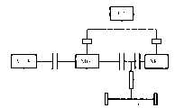
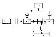
参考图1,该图为本发明的优选实施方式的结构示意图,为本发明混合动力输出装置的示意图,此动力输出装置用于输出动力至车轮驱动轴,它包括:带有输出轴的发动机1,用于储备和输出电能的电池6,设置于发动机1输出轴与车轮驱动轴8之间的第一电动发电机2及第二电动发电机3,设置于发动机1的输出轴与第一电动发电机2之间的第一离合器4,设置于第一电动发电机2与驱动轴8之间的第二离合器5,第三离合器11位于所述第二电动发电机3的旋转轴上,且定速比减速机构7的输入轴位于所述第二离合器5和所述第三离合器11之间。With reference to Fig. 1, this figure is the structure schematic diagram of the preferred embodiment of the present invention, is the schematic diagram of the hybrid power output device of the present invention, and this power output device is used for outputting power to the wheel drive shaft, and it comprises:
按照图1所示的实施例,发动机1、第一离合器4、第一电动发电机2、第二离合器5、第三离合器11、第二电动发电机3依次顺序连接,第一电动发电机2和第二电动发电机3的转轴与发动机1的输出轴同轴设置。发动机1的输出轴与第一电动发电机2的转轴通过第一离合器4连接,第一电动发电机2的转轴与第二电动发电机3的转轴通过第二离合器5和第三离合器11连接,在第二离合器5与第三离合器11之间连接驱动轴8。According to the embodiment shown in Figure 1, the
第二电动发电机3和第一电动发电机2为交流电机,如永磁同步电机;这两个电动发电机均可以作为发电机和电动机使用,此时其工作状态分别为发电和电动工作状态。电池6为一可控的能量存储单元,可以是锂电池、铁电池、镍氢电池、镍铬电池等,在此不作限定;第一电动发电机2和第二电动发电机3分别通过第一功率变换器9和第二功率变换器10与电池6连接,第一功率变换器9和第二功率变换器10可进行双向的功率变换,因而通过功率变换单元的转化,两电动发电机可将电池6中储存的电能转化为机械动力输出,也可将动力转化为电能存储在电池6中。The second motor-
在图1所示的实施例中,第一电动发电机2与发动机1、驱动轴8和电池6均相连,可使能量在所述发动机1的输出轴、电池7及驱动轴8之间进行转化或传递。当发动机1需要启动时,第一电动发电机2通过第一离合器4与发动机1的输出轴结合,并通过将电池6中的电能转化为机械动力,用于产生充足的转矩以启动发动机1。当电池6中的存储能量需要补充时,第一电动发电机2也可通过在发动机1的驱动下产生能量,并输出至电池6,以电能的形式存储在电池6中。In the embodiment shown in FIG. 1 , the
第二电动发电机3设计为在低速下的效率高于第一电动发电机2,其具有比第一电动发电机2大的功率,主要用于在车辆起步或低速行驶过程中单独驱动车轮。当车辆需要较大的牵引力时,第二电动发电机3与第一电动发电机2共同驱动车轮,实现大转矩的输出。第一电动发电机2设计为在高转速下的效率高于第二电动发电机3,可用于独立启动发动机1,还可用于单独以纯电力形式驱动车轮。The second motor-
由于发动机1的高效率工作区一般位于相对高的转速下,因此,车辆在从停车状态运转到此相对较高的转速这段过程中,使用电动发电机的电动工作来驱动车轮可以使发动机1不参与工作,从而可以避免发动机1工作在非高效区所引起的油耗及有害排放物的增加。Since the high-efficiency working area of the
当第一电动发电机2用于与第二电动发电机3共同纯电力地驱动车轮时,第二离合器5需转换为结合状态,可以通过电池6储存的电能使第一电动发电机2的转速与第二电动发电机3的转速接近,通过趋近于零的转速差使得两电动发电机的转轴通过第二离合器5和第三离合器11结合起来。这种结合形式的纯电力驱动具有较大的输出转矩,对于车辆低转速时的大转矩需求,此第一电动发电机2与第二电动发电机3共同纯电力驱动的形式也能够满足,而不需要启动发动机1,避免发动机1工作在非高效工作区。When the first motor-
发动机1可采用汽油或柴油等作为燃料,并通过输出轴8输出动力。The
本发明的定速比减速机构7可以是常啮合的齿轮传动减速机构、链条传动减速机构及摩擦传动减速机构等,只要在满足减速的同时减速比恒定即可。The constant speed
下面结合图2至图13具体说明:Below in conjunction with Fig. 2 to Fig. 13 specific description:
图2、图3和图4表示仅基于电动发电机的动力输出对驱动轴8驱动的动力输出形式,这种形式属于混合动力系统中通常所称的纯电动模式,即发动机1不工作,仅靠电动发电机的工作实现动力的输出。Fig. 2, Fig. 3 and Fig. 4 show the power output form driven to the drive shaft 8 only based on the power output of the motor generator, this form belongs to the so-called pure electric mode in the hybrid power system, that is, the
在本发明的结构下,这种动力输出形式中,发动机1不工作,第一离合器4断开,动力的输出可通过三种不同的能量流动形式来实现,分别如图2、图3和图4所示。Under the structure of the present invention, in this power output form, the
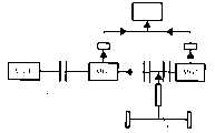
图2所示为第一电动发电机2和第二电动发电机3同时对驱动轴8输出动力的形式,此时第二离合器5和第三离合器11均处于结合状态,因此,两电动发电机的旋转轴可同时将动力传递给驱动轴8;第一电动发电机2和第二电动发电机3工作在电动模式之下,电池6为两电动发电机提供可以转化为动力的电能。如图2中箭头所示,电池6提供电能给第一电动发电机2和第二电动发电机3,经过电动转化,第一电动发电机2和第二电动发电机3输出动力至驱动轴8。Figure 2 shows the form in which the first motor-
图3所示为仅基于第二电动发电机3驱动的动力输出形式,此时第二离合器5处于断开状态,第三离合器11处于结合状态,第一电动发电机2不工作,第二电动发电机3在电动工作状态之下,电池6为第二电动发电机3提供可以转化为动力的电能。如图3中箭头所示,电池6提供电能给第二电动发电机3,经过电动转化,第二电动发电机3输出动力至驱动轴8。Figure 3 shows the power output form driven only based on the second motor-
图4所示为仅基于第一电动发电机2驱动的动力输出形式,此时第二离合器5处于结合状态,第三离合器11处于断开状态,第二电动发电机3不工作,第一电动发电机2在电动工作状态之下,电池6为第一电动发电机2提供可以转化为动力的电能。如图4中箭头所示,电池6提供电能给第一电动发电机2,经过电动转化,第一电动发电机2输出动力至驱动轴8。由于切断了第二电动发电机3与驱动轴8的连接,因此也不会引起第二电动发电机3的空转,而造成能量的浪费。Figure 4 shows the power output form driven only based on the first motor-
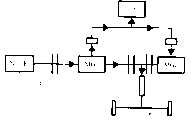
图5和图6所示为发动机1工作,但是对驱动轴8的驱动仅基于第二电动发电机3的动力输出的形式。这种形式是混合动力系统中通常所称的串联模式。5 and 6 show that the
在这种输出形式中,第二离合器5处于断开状态,第三离合器11处于结合状态,从而断开第一电动发电机2和发动机1与驱动轴8的机械连接;第一离合器4处于结合状态,连接发动机1的输出轴和第一电动发电机2的旋转轴;发动机1产生动力输送给第一电动发电机2,第一电动发电机2处于发电工作状态,第二电动发电机3处于电动工作状态;如图5箭头所示,第一电动发电机2发出的电能一部分传递给第二电动发电机3,此时电池6需要能量补充,第一电动发电机2另一部分电能输送给电池6用作储存,第二电动发电机3输送动力至驱动轴8。如图6箭头所示,第一电动发电机2发出的电能传递给第二电动发电机3,电池6将电能输送给第二电动发电机3,第二电动发电机3输送动力至驱动轴8。In this output form, the
图7、图8和图9所示发动机1输出动力至驱动轴8,且消耗电池6的电能来产生驱动力至驱动轴8的动力输出形式。这种形式是混合动力系统中通常所称的并联模式。The
这种动力输出形式中,第一离合器4、第二离合器5均处于结合状态,第三离合器11处于结合或断开状态,从而使发动机的输出轴1与第一电动发电机2的旋转轴机械连接,使第一电动发电机2和第二电动发电机3同时与驱动轴机械连接;根据第一、第二电动发电机的工作状态不同,这种动力输出形式可以有不同的能量流动形式。In this power output form, the
图7所示为上述的一种能量流动形式,此时,第一离合器4、第二离合器5均处于结合状态,第三离合器11处于结合状态,第一电动发电机2和第二电动发电机3均工作在电动模式之下,电池6为它们提供工作所需的电能。如图7箭头所示,发动机1动作,将动力通过第一电动发电机2的旋转轴传递至驱动轴8,第一电动发电机2和第二电动发电机3根据驱动所需的动力将电池6的电能进行转化,并同时将动力输出至驱动轴8。Figure 7 shows the above-mentioned energy flow form. At this time, the
图8所示为上述的其它能量流动形式,此时,第一离合器4、第二离合器5均处于结合状态,第三离合器11处于结合状态,第一电动发电机2空转,第二电动发电机3工作在电动模式之下,电池6为其提供工作所需的电能。如图8箭头所示,发动机1动作,将动力通过第一电动发电机2的旋转轴传递至驱动轴8,第二电动发电机3根据驱动所需的动力将电池6的电能进行转化,并将动力输出至驱动轴8。Figure 8 shows other energy flow forms mentioned above. At this moment, the
图9所示为上述的另外一种能量流动形式,此时,第一离合器4、第二离合器5均处于结合状态,第三离合器11处于断开状态,第二电动发电机3与输出轴8断开机械连接,第一电动发电机2处于工作状态,电池6为其提供工作所需的电能。如图9箭头所示,发动机1工作,将动力通过第一电动发电机2的旋转轴传递至驱动轴8,同时,电池6为第一电动发电机2提供电能,并与发动机1一起驱动车轮。Figure 9 shows another form of energy flow mentioned above. At this time, the
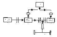
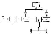
图10和图11所示为发动机1输出动力、第一电动发电机2在发电工作状态、第二电动发电机3在电动工作状态的动力输出形式,这种形式属于混合动力系统所称的混联模式。Figure 10 and Figure 11 show the output power of the
此时,发动机1的部分动力直接输送至驱动轴,另一部分动力用于驱动第一电动发电机2工作在发电模式之下,第二电动发电机3工作在电动模式。如图10箭头所示,此时第一电动发电机2产生的电能一部分直接传递给第二电动发电机3,使第二电动发电机3电动工作驱动车轮,另一部分电能输送给电池6用作电能补充。如图11箭头所示,此时第一电动发电机2产生的电能直接传递给第二电动发电机3,电池6也输送电能至第二电动发电机3,使第二电动发电机3电动工作驱动车轮。At this time, part of the power of the
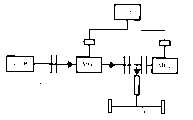
图12和图13所示为仅由发动机1输出动力至驱动轴8的动力输出形式,这种形式属于常称的纯发动机模式,此时,第一离合器4和第二离合器5均结合,第三离合器11断开。由于切断了第二电动发电机3与驱动轴8的连接,因此在驱动轴8输出动力的同时,也不会引起第二电动发电机3的空转而造成能量的浪费。Fig. 12 and Fig. 13 show the power output form that only the
图12所示为第一电动发电机2处于空转状态,第二电动发电机3不工作的情况,第一电动发电机2的旋转轴将发动机1的输出动力传递给驱动轴8。如图12箭头所示,发动机1动作,将动力通过第一电动发电机2的旋转轴传递至驱动轴8。FIG. 12 shows the situation that the first motor-
图13所示为第一电动发电机2同时将发动机1的部分动能转化为电能储存在电池6中,用于补充电池6的能量储备,其旋转轴将发动机1另一部分输出动力传递给驱动轴8。如图13箭头所示,发动机1动作,其一部分动力通过第一电动发电机2的旋转轴传递至驱动轴8,另一部分动力通过第一电动发电机2转化为动能储存在电池6中。Figure 13 shows that the
图14、图15所示为本发明能量再生形式的说明图。Fig. 14 and Fig. 15 are explanatory diagrams showing the energy regeneration form of the present invention.
在车辆随着制动器的制动而进行减速行驶或者停止的状态下,本发明的结构可进行能量的再生,此时使电动发电机工作在发电模式之下,将驱动轴8回馈的动力转化为电能输送至电池6,以最大的限度对电池6进行充电。根据第二离合器5的结合/断开状态可以有不同的能量再生形式。When the vehicle is decelerating or stopping with the braking of the brake, the structure of the present invention can regenerate energy. At this time, the motor generator is made to work in the power generation mode, and the power fed back by the drive shaft 8 is converted into The electric energy is delivered to the
图14所示为第二离合器5和第三离合器11均结合时的能量再生形式,此时第一电动发电机2和第二电动发电机3的旋转轴均与驱动轴8相连,第一电动发电机2和第二电动发电机3工作在发电模式之下,电池6存储再生的电能。如图14箭头所示,驱动轴8将动力回馈给第一电动发电机2和第二电动发电机3,第一电动发电机2和第二电动发电机3分别将动力转化为电能并输送至电池6,实现能量的再生。Figure 14 shows the form of energy regeneration when both the
图15所示为第二离合器5断开、第三离合器11结合时的能量再生形式,此时第二电动发电机3的旋转轴与驱动轴8相连,第二电动发电机3工作在发电模式之下,电池6存储再生的电能。如图15箭头所示,驱动轴将动力回馈给第二电动发电机3,第二电动发电机3将动力转化为电能并输送至电池6,实现能量的再生。Figure 15 shows the form of energy regeneration when the
图16所示为本发明的驻车充电模式。Figure 16 shows the parking charging mode of the present invention.
在这种模式中,第二离合器5断开且第二电动发电机3在不工作状态,发动机1驱动第一电动发电机2在发电的工作状态,并将电能储存在电池6中,如图16箭头所示,发动机1工作,并将动力传递给第一电动发电机2,第一电动发电机2将动力转化为电能输送至电池6。In this mode, the
Claims (9)
Translated fromChinesePriority Applications (4)
| Application Number | Priority Date | Filing Date | Title |
|---|---|---|---|
| CNA2006101577276ACN101209667A (en) | 2006-12-25 | 2006-12-25 | hybrid power output |
| EP07846124.1AEP2094516B1 (en) | 2006-12-25 | 2007-12-21 | Hybrid power output system |
| PCT/CN2007/071298WO2008077346A1 (en) | 2006-12-25 | 2007-12-21 | Hybrid power output system |
| US12/521,055US8307924B2 (en) | 2006-12-25 | 2007-12-21 | Hybrid power output system |
Applications Claiming Priority (1)
| Application Number | Priority Date | Filing Date | Title |
|---|---|---|---|
| CNA2006101577276ACN101209667A (en) | 2006-12-25 | 2006-12-25 | hybrid power output |
Publications (1)
| Publication Number | Publication Date |
|---|---|
| CN101209667Atrue CN101209667A (en) | 2008-07-02 |
Family
ID=39562106
Family Applications (1)
| Application Number | Title | Priority Date | Filing Date |
|---|---|---|---|
| CNA2006101577276APendingCN101209667A (en) | 2006-12-25 | 2006-12-25 | hybrid power output |
Country Status (4)
| Country | Link |
|---|---|
| US (1) | US8307924B2 (en) |
| EP (1) | EP2094516B1 (en) |
| CN (1) | CN101209667A (en) |
| WO (1) | WO2008077346A1 (en) |
Cited By (26)
| Publication number | Priority date | Publication date | Assignee | Title |
|---|---|---|---|---|
| CN101659204A (en)* | 2008-08-29 | 2010-03-03 | 比亚迪股份有限公司 | Hybrid driving system and driving method thereof |
| CN101920653A (en)* | 2009-06-17 | 2010-12-22 | 上海捷能汽车技术有限公司 | Power transmission unit and transmission control method of hybrid driving system |
| CN102198791A (en)* | 2010-03-24 | 2011-09-28 | 沃依特专利有限责任公司 | Driving device |
| CN102310756A (en)* | 2010-06-29 | 2012-01-11 | 北汽福田汽车股份有限公司 | Hybrid power automobile and power assembly for hybrid power automobile |
| CN102555769A (en)* | 2012-03-12 | 2012-07-11 | 重庆大学 | Serial-parallel combined type double-motor hybrid power drive assembly with multiple operating modes |
| CN101585314B (en)* | 2009-06-08 | 2012-12-05 | 浙江吉利汽车研究院有限公司 | Hybrid power-driven system |
| CN103201153A (en)* | 2010-11-04 | 2013-07-10 | 丰田自动车株式会社 | Control device of hybrid vehicle |
| CN103287562A (en)* | 2013-06-07 | 2013-09-11 | 哈尔滨耦合动力工程技术中心有限公司 | Diesel engine, electric generator and electromotor integrated ship hybrid power system and hybrid method |
| CN103358878A (en)* | 2013-08-08 | 2013-10-23 | 哈尔滨耦合动力工程技术中心有限公司 | Energy-recovery magnetic stress coupling automobile hybrid power charging system and charging method |
| CN103386880A (en)* | 2013-08-14 | 2013-11-13 | 哈尔滨耦合动力工程技术中心有限公司 | Environment-friendly magnetic-coupling automobile hybrid power system and hybrid method |
| CN103407364A (en)* | 2013-07-27 | 2013-11-27 | 哈尔滨耦合动力工程技术中心有限公司 | Engine and generator gear box driven hybrid power system for cars and hybrid method |
| CN103978880A (en)* | 2013-02-08 | 2014-08-13 | 高效动力传动系统公司 | Powertrain configurations for two-motor, two-clutch hybrid electric vehicles |
| CN104249733A (en)* | 2013-06-28 | 2014-12-31 | 上海汽车集团股份有限公司 | Automobile energy recovery control method |
| CN105774537A (en)* | 2016-03-24 | 2016-07-20 | 重庆大学 | Range extending type electric automobile power system adopting double-clutch two-gear automatic transmission |
| CN105774795A (en)* | 2014-12-19 | 2016-07-20 | 北汽福田汽车股份有限公司 | Torque distribution method and system for parallel type hybrid power system vehicle |
| CN103192824B (en)* | 2012-01-10 | 2016-12-28 | 福特全球技术公司 | For the method improving the fuel economy of plug-in hybrid electric vehicle |
| CN108001205A (en)* | 2016-10-31 | 2018-05-08 | 比亚迪股份有限公司 | Power drive system and there is its vehicle |
| CN108482099A (en)* | 2018-04-03 | 2018-09-04 | 朱珍 | A kind of automobile-used combined-circulation formula dynamical system of vehicle intelligent |
| CN109228843A (en)* | 2017-07-10 | 2019-01-18 | 现代自动车株式会社 | There are two the dynamical systems of motor for tool |
| US10369878B2 (en) | 2013-02-08 | 2019-08-06 | Cummins Electrified Power Na Inc. | Powertrain configurations for two-motor, two-clutch hybrid electric vehicles |
| CN110341454A (en)* | 2019-07-11 | 2019-10-18 | 山西成功汽车制造有限公司 | A dual-engine hybrid heavy-duty vehicle driving system and its application method |
| US10464423B2 (en) | 2014-06-15 | 2019-11-05 | Cummins Electric Power NA Inc. | Vehicle with AC-to-DC inverter system for vehicle-to-grid power integration |
| CN110450616A (en)* | 2019-08-14 | 2019-11-15 | 四川阿尔特新能源汽车有限公司 | Drive system, drive control method, apparatus and hybrid vehicle |
| CN110450618A (en)* | 2019-08-14 | 2019-11-15 | 四川阿尔特新能源汽车有限公司 | Hybrid electric drive system, drive control method, apparatus and hybrid vehicle |
| US10836375B2 (en) | 2013-02-08 | 2020-11-17 | Cummins Electrified Power Na Inc. | Powertrain configurations for single-motor, two-clutch hybrid electric vehicles |
| CN112659879A (en)* | 2020-12-28 | 2021-04-16 | 中国第一汽车股份有限公司 | Longitudinal vehicle power assembly and vehicle power control method |
Families Citing this family (40)
| Publication number | Priority date | Publication date | Assignee | Title |
|---|---|---|---|---|
| TWI330218B (en)* | 2004-10-29 | 2010-09-11 | Tai Her Yang | Split serial-parallel hybrid dual-power drive system |
| CN101535075A (en)* | 2006-12-08 | 2009-09-16 | 比亚迪股份有限公司 | Hybrid power output system |
| US8290653B2 (en)* | 2008-08-27 | 2012-10-16 | Ecomotors International, Inc. | Powertrain with multiple, selectable power sources |
| US8337359B2 (en) | 2008-08-27 | 2012-12-25 | EcoMotors International | Hybrid engine system |
| EP2344367A1 (en)* | 2008-10-15 | 2011-07-20 | Getrag Ford Transmissions GmbH | Vehicle having drive train |
| US8955625B2 (en)* | 2009-09-11 | 2015-02-17 | ALTe Technologies, Inc. | Stackable motor |
| CN102085795B (en)* | 2009-12-04 | 2015-04-15 | 上海汽车集团股份有限公司 | Hybrid driving system of vehicle clutch and power coupling synchronizer combined gear shift |
| CN101875297B (en)* | 2009-12-10 | 2013-07-10 | 安徽巨一自动化装备有限公司 | Double-motor hybrid driving and speed changing device |
| CN102310755B (en)* | 2010-06-29 | 2014-05-28 | 北汽福田汽车股份有限公司 | Power coupling device and control device thereof, and hybrid power system |
| US8678116B2 (en)* | 2010-12-31 | 2014-03-25 | Cummins Inc. | Accessory drive configuration |
| DE102011106399A1 (en)* | 2011-07-02 | 2013-01-03 | Magna E-Car Systems Gmbh & Co Og | powertrain |
| WO2013094005A1 (en)* | 2011-12-19 | 2013-06-27 | トヨタ自動車株式会社 | Drive control device for hybrid vehicle |
| DE112012006106B4 (en) | 2012-03-26 | 2023-07-27 | Toyota Jidosha Kabushiki Kaisha | vehicle control device |
| DE102013013623B4 (en)* | 2012-08-29 | 2022-06-30 | Kanzaki Kokyukoki Mfg. Co., Ltd. | Motor control system for an electric motor driven vehicle |
| US9045136B2 (en) | 2013-02-08 | 2015-06-02 | Efficient Drivetrains, Inc. | Systems and methods for implementing dynamic operating modes and control policies for hybrid electric vehicles |
| US10384527B2 (en)* | 2013-02-08 | 2019-08-20 | Cummins Electrified Power Na Inc. | Four wheel drive powertrain configurations for two-motor, two-clutch hybrid electric vehicles |
| CN103241117A (en)* | 2013-05-16 | 2013-08-14 | 哈尔滨耦合动力工程技术中心有限公司 | Magnetic coupling series structure automobile hybrid system and working method thereof |
| US20150037171A1 (en)* | 2013-08-01 | 2015-02-05 | Chevron U.S.A. Inc. | Electric submersible pump having a plurality of motors operatively coupled thereto and methods of using |
| GB2531767A (en)* | 2014-10-29 | 2016-05-04 | Bamford Excavators Ltd | Working Machine |
| GB2532731A (en)* | 2014-11-25 | 2016-06-01 | Eric Hawksley Graeme | Hybrid power system |
| DE102015000466B4 (en)* | 2015-01-15 | 2016-11-17 | Audi Ag | Drive device for a motor vehicle and motor vehicle |
| CN105082966A (en)* | 2015-09-09 | 2015-11-25 | 华英汽车集团有限公司 | Dual-motor power system, gear shifting method and electric automobile |
| CN108473042B (en) | 2015-12-07 | 2022-07-19 | 德纳重型车辆系统集团有限责任公司 | Distributed drivetrain architecture for commercial vehicles with hybrid powertrains and dual-range disconnect axles |
| US10486521B2 (en) | 2015-12-07 | 2019-11-26 | Dana Heavy Vehicle Systems Group, Llc | Distributed drivetrain architectures for commercial vehicles with a hybrid electric powertrain |
| EP3436301B1 (en) | 2016-03-28 | 2022-05-04 | Dana Heavy Vehicle Systems Group, LLC | Single electric motor drive axle with multiple ratios |
| WO2017172722A1 (en) | 2016-03-28 | 2017-10-05 | Dana Heavy Vehicle Systems Group, Llc | Electric drivetrain axles with multi-speed gearboxes |
| US10857881B2 (en) | 2016-11-15 | 2020-12-08 | Dana Heavy Vehicle Systems Group, Llc | Electric drivetrain for a tandem drive axle |
| JP6353576B1 (en)* | 2017-03-22 | 2018-07-04 | 株式会社ユニバンス | Power transmission device |
| CN109515146A (en)* | 2017-09-18 | 2019-03-26 | 郑州宇通客车股份有限公司 | A kind of pure electric coach and its dynamical system |
| DE102017130494A1 (en)* | 2017-12-19 | 2019-06-19 | Schaeffler Technologies AG & Co. KG | Hybrid powertrain |
| US11407307B2 (en)* | 2020-03-23 | 2022-08-09 | Arvinmeritor Technology, Llc | Drive axle system having multiple electric motors |
| DE102020209516A1 (en)* | 2020-07-29 | 2022-02-03 | Zf Friedrichshafen Ag | Drive train for a hybrid vehicle |
| WO2022204737A1 (en)* | 2021-04-01 | 2022-10-06 | Jacobs Engineering Group Cc | Super range extension control system for electric vehicles (evs) |
| US11376943B1 (en) | 2021-08-13 | 2022-07-05 | Oshkosh Defense, Llc | Electrified military vehicle |
| US12319160B1 (en) | 2021-08-13 | 2025-06-03 | Oshkosh Defense, Llc | Convoy operations for electrified military vehicles |
| US12130122B1 (en) | 2021-08-13 | 2024-10-29 | Oshkosh Defense, Llc | Military vehicle with battery armor |
| US12351028B1 (en) | 2021-08-13 | 2025-07-08 | Oshkosh Defense, Llc | Military vehicle with modular battery units |
| US11498409B1 (en) | 2021-08-13 | 2022-11-15 | Oshkosh Defense, Llc | Electrified military vehicle |
| US12311754B1 (en) | 2021-08-13 | 2025-05-27 | Oshkosh Defense, Llc | Power export system for a military vehicle |
| US12358361B1 (en)* | 2021-08-13 | 2025-07-15 | Oshkosh Defense, Llc | Electrified military vehicle with electric weaponry support system |
Family Cites Families (53)
| Publication number | Priority date | Publication date | Assignee | Title |
|---|---|---|---|---|
| US5845731A (en)* | 1996-07-02 | 1998-12-08 | Chrysler Corporation | Hybrid motor vehicle |
| JPH11280512A (en)* | 1998-03-30 | 1999-10-12 | Nissan Motor Co Ltd | Hybrid vehicle |
| JP3536658B2 (en)* | 1998-03-31 | 2004-06-14 | 日産自動車株式会社 | Drive control device for hybrid vehicle |
| US6276472B1 (en)* | 1998-04-01 | 2001-08-21 | Denso Corporation | Control system for hybrid vehicle |
| US5931757A (en)* | 1998-06-24 | 1999-08-03 | General Motors Corporation | Two-mode, compound-split electro-mechanical vehicular transmission |
| JP3449226B2 (en)* | 1998-07-03 | 2003-09-22 | 日産自動車株式会社 | Battery control device for hybrid vehicle |
| JP3409701B2 (en)* | 1998-07-03 | 2003-05-26 | 日産自動車株式会社 | Control device for hybrid vehicle |
| US6554088B2 (en)* | 1998-09-14 | 2003-04-29 | Paice Corporation | Hybrid vehicles |
| JP3514142B2 (en)* | 1998-11-04 | 2004-03-31 | 日産自動車株式会社 | Vehicle control device |
| US6203468B1 (en)* | 1998-11-18 | 2001-03-20 | Fuji Jukogyo Kabushiki Kaisha | Control device for hybrid vehicle and method thereof |
| DE19917665A1 (en)* | 1999-04-19 | 2000-10-26 | Zahnradfabrik Friedrichshafen | Hybrid drive for motor vehicle has IC engine coupled to motor through clutch and to gears through second clutch, second motor coupled permanently to gears forming hybrid drive with IC engine |
| DE10036504B4 (en)* | 1999-08-02 | 2011-05-19 | Schaeffler Technologies Gmbh & Co. Kg | powertrain |
| FR2809352B1 (en) | 2000-05-25 | 2002-08-16 | Renault | DRIVE UNIT OF A HYBRID VEHICLE AND ITS CONTROL METHOD |
| JP3569210B2 (en)* | 2000-08-11 | 2004-09-22 | 本田技研工業株式会社 | Power transmission device for hybrid vehicle and control method therefor |
| US6450275B1 (en)* | 2000-11-02 | 2002-09-17 | Ford Motor Company | Power electronics cooling for a hybrid electric vehicle |
| JP2002199506A (en)* | 2000-12-22 | 2002-07-12 | Mazda Motor Corp | Hybrid drive device |
| US6478705B1 (en) | 2001-07-19 | 2002-11-12 | General Motors Corporation | Hybrid electric powertrain including a two-mode electrically variable transmission |
| JP3707411B2 (en)* | 2001-09-28 | 2005-10-19 | トヨタ自動車株式会社 | Power output apparatus and automobile equipped with the same |
| CN1301200C (en)* | 2002-09-13 | 2007-02-21 | 本田技研工业株式会社 | hybrid vehicle |
| US6962545B2 (en)* | 2002-09-23 | 2005-11-08 | Bae Systems Onctrols | Multi-range parallel-hybrid continuously variable transmission |
| US6600980B1 (en)* | 2002-09-26 | 2003-07-29 | Ford Global Technologies, Llc | Torque reversal reduction strategy for a hybrid vehicle |
| CN1291855C (en) | 2002-12-08 | 2006-12-27 | 中国第一汽车集团公司 | Dual-motor hybrid vehicle powertrain |
| EP1524145A3 (en)* | 2003-10-15 | 2006-01-04 | Nissan Motor Company, Limited | Drive train for hybrid vehicle |
| JP4069901B2 (en)* | 2004-05-20 | 2008-04-02 | トヨタ自動車株式会社 | Hybrid vehicle drivetrain |
| CN100354154C (en)* | 2004-08-16 | 2007-12-12 | 上海比亚迪有限公司 | Mixing power automobile power system |
| AT8336U1 (en)* | 2004-09-27 | 2006-06-15 | Magna Steyr Fahrzeugtechnik Ag | DRIVE UNIT FOR MOTOR VEHICLE WITH HYBRID DRIVE IN LENGTH ORDER |
| JP4341611B2 (en)* | 2005-11-09 | 2009-10-07 | 日産自動車株式会社 | Engine restart control device for hybrid vehicle |
| JP4301212B2 (en)* | 2005-06-03 | 2009-07-22 | 日産自動車株式会社 | Vehicle control device |
| US7468014B2 (en)* | 2005-10-21 | 2008-12-23 | Gm Global Technology Operations, Inc. | Hybrid architecture incorporating three motor generators and planetary gear arrangment having a stationary member |
| US7625307B2 (en)* | 2005-10-21 | 2009-12-01 | Gm Global Technology Operations, Inc. | Mechatronic hybrid transmissions having two planetary gear sets and three motor/generators |
| US7507173B2 (en)* | 2005-10-21 | 2009-03-24 | Gm Global Technology Operations, Inc. | Hybrid architecture incorporating three motor generators and planetary gear sets with two fixed interconnections |
| US7371201B2 (en)* | 2005-10-21 | 2008-05-13 | Gm Global Technology Operations, Inc. | Hybrid transmissions having three motor/generators and three interconnected planetary gear members |
| US7344464B2 (en)* | 2005-10-21 | 2008-03-18 | Gm Global Technology Operations, Inc. | Hybrid architecture incorporating three motor generators and a stationary planetary gear member |
| US7371202B2 (en)* | 2005-10-21 | 2008-05-13 | Gm Global Technology Operations, Inc. | Mechatronic hybrid transmissions having three planetary gear sets and three motor/generators |
| US7341535B2 (en)* | 2005-10-21 | 2008-03-11 | Gm Global Technology Operations, Inc. | Hybrid transmissions having three motor/generators and a stationary planetary gear member |
| US7422534B2 (en)* | 2005-10-21 | 2008-09-09 | Gm Global Technology Operations, Inc. | Hybrid transmissions having three motor/generators and three interconnected planetary gear sets |
| JP4077003B2 (en)* | 2005-10-26 | 2008-04-16 | トヨタ自動車株式会社 | Electric vehicle drive control device and control method thereof |
| JP4215070B2 (en)* | 2006-04-26 | 2009-01-28 | トヨタ自動車株式会社 | Control device for vehicle drive device |
| US7908063B2 (en)* | 2006-05-03 | 2011-03-15 | GM Global Technology Operations LLC | Synchronous shift execution for hybrid transmission |
| US7591747B2 (en)* | 2006-05-25 | 2009-09-22 | Gm Global Technology Operations, Inc. | Electrically variable transmission having three planetary gear sets, two fixed interconnections and clutched input |
| US7374506B2 (en)* | 2006-05-25 | 2008-05-20 | Gm Global Technology Operations, Inc. | Electrically variable transmission having three planetary gear sets, a stationary member, three fixed interconnections and clutched input |
| JP4492585B2 (en)* | 2006-05-29 | 2010-06-30 | 日産自動車株式会社 | Hybrid vehicle control device and hybrid vehicle control method. |
| US7507174B2 (en)* | 2006-07-14 | 2009-03-24 | Gm Global Technology Operations, Inc. | Electrically variable transmission having three planetary gear sets |
| US7494436B2 (en)* | 2006-07-24 | 2009-02-24 | Gm Global Technology Operations, Inc. | Hybrid architecture incorporating three interconnected gear sets and brakes |
| US7479080B2 (en)* | 2006-07-24 | 2009-01-20 | Gm Global Technology Operations, Inc. | Hybrid architecture incorporating three motor generators and brakes |
| US7748482B2 (en)* | 2006-10-25 | 2010-07-06 | Gm Global Technology Operations, Inc. | Accessory drive system for a hybrid vehicle |
| US7479082B2 (en)* | 2006-11-17 | 2009-01-20 | Gm Global Technology Operations, Inc. | Hybrid powertrain having three interconnecting members and brakes |
| US7481731B2 (en)* | 2006-11-17 | 2009-01-27 | Gm Global Technology Operations, Inc. | Hybrid powertrain having three planetary gearsets and brakes |
| US7597648B2 (en)* | 2006-11-28 | 2009-10-06 | Gm Global Technology Operations, Inc. | Input brake providing electric only fixed gear |
| CN101535075A (en)* | 2006-12-08 | 2009-09-16 | 比亚迪股份有限公司 | Hybrid power output system |
| CN101209666A (en)* | 2006-12-25 | 2008-07-02 | 比亚迪股份有限公司 | Mixed power outputting device |
| US7704176B2 (en)* | 2007-01-31 | 2010-04-27 | Gm Global Technology Operations, Inc. | Electrically variable transmission device using multiple pairings of electrical machines |
| US7980980B2 (en)* | 2007-11-14 | 2011-07-19 | GM Global Technology Operations LLC | Hybrid powertrain |
- 2006
- 2006-12-25CNCNA2006101577276Apatent/CN101209667A/enactivePending
- 2007
- 2007-12-21EPEP07846124.1Apatent/EP2094516B1/enactiveActive
- 2007-12-21USUS12/521,055patent/US8307924B2/enactiveActive
- 2007-12-21WOPCT/CN2007/071298patent/WO2008077346A1/enactiveApplication Filing
Cited By (40)
| Publication number | Priority date | Publication date | Assignee | Title |
|---|---|---|---|---|
| CN101659204B (en)* | 2008-08-29 | 2015-07-22 | 比亚迪股份有限公司 | Hybrid driving system and driving method thereof |
| CN101659204A (en)* | 2008-08-29 | 2010-03-03 | 比亚迪股份有限公司 | Hybrid driving system and driving method thereof |
| CN101585314B (en)* | 2009-06-08 | 2012-12-05 | 浙江吉利汽车研究院有限公司 | Hybrid power-driven system |
| CN101920653A (en)* | 2009-06-17 | 2010-12-22 | 上海捷能汽车技术有限公司 | Power transmission unit and transmission control method of hybrid driving system |
| CN101920653B (en)* | 2009-06-17 | 2015-02-18 | 上海捷能汽车技术有限公司 | Power transmission unit and transmission control method of hybrid driving system |
| CN102198791A (en)* | 2010-03-24 | 2011-09-28 | 沃依特专利有限责任公司 | Driving device |
| CN102310756A (en)* | 2010-06-29 | 2012-01-11 | 北汽福田汽车股份有限公司 | Hybrid power automobile and power assembly for hybrid power automobile |
| US9102322B2 (en) | 2010-11-04 | 2015-08-11 | Toyota Jidosha Kabushiki Kaisha | Control apparatus for hybrid vehicle |
| US9233683B2 (en) | 2010-11-04 | 2016-01-12 | Toyota Jidosha Kabushiki Kaisha | Control apparatus for hybrid vehicle |
| CN103201153B (en)* | 2010-11-04 | 2016-01-20 | 丰田自动车株式会社 | Controls for hybrid vehicles |
| CN103201153A (en)* | 2010-11-04 | 2013-07-10 | 丰田自动车株式会社 | Control device of hybrid vehicle |
| CN103192824B (en)* | 2012-01-10 | 2016-12-28 | 福特全球技术公司 | For the method improving the fuel economy of plug-in hybrid electric vehicle |
| US9580062B2 (en) | 2012-01-10 | 2017-02-28 | Ford Global Technologies, Llc | Method for increasing fuel economy of plug-in hybrid electric vehicles |
| CN102555769A (en)* | 2012-03-12 | 2012-07-11 | 重庆大学 | Serial-parallel combined type double-motor hybrid power drive assembly with multiple operating modes |
| CN102555769B (en)* | 2012-03-12 | 2014-12-10 | 重庆大学 | Serial-parallel combined type double-motor hybrid power drive assembly with multiple operating modes |
| CN103978880A (en)* | 2013-02-08 | 2014-08-13 | 高效动力传动系统公司 | Powertrain configurations for two-motor, two-clutch hybrid electric vehicles |
| US10369878B2 (en) | 2013-02-08 | 2019-08-06 | Cummins Electrified Power Na Inc. | Powertrain configurations for two-motor, two-clutch hybrid electric vehicles |
| US10836375B2 (en) | 2013-02-08 | 2020-11-17 | Cummins Electrified Power Na Inc. | Powertrain configurations for single-motor, two-clutch hybrid electric vehicles |
| CN103978880B (en)* | 2013-02-08 | 2019-07-19 | 高效动力传动系统公司 | Powertrain Configuration for Dual Motor Dual Clutch Hybrid Vehicle |
| CN103287562A (en)* | 2013-06-07 | 2013-09-11 | 哈尔滨耦合动力工程技术中心有限公司 | Diesel engine, electric generator and electromotor integrated ship hybrid power system and hybrid method |
| CN103287562B (en)* | 2013-06-07 | 2016-02-24 | 哈尔滨耦合动力工程技术中心有限公司 | The boats and ships hybrid power system that diesel power generation electric motor is integrated and mixed method |
| CN104249733A (en)* | 2013-06-28 | 2014-12-31 | 上海汽车集团股份有限公司 | Automobile energy recovery control method |
| CN103407364A (en)* | 2013-07-27 | 2013-11-27 | 哈尔滨耦合动力工程技术中心有限公司 | Engine and generator gear box driven hybrid power system for cars and hybrid method |
| CN103358878A (en)* | 2013-08-08 | 2013-10-23 | 哈尔滨耦合动力工程技术中心有限公司 | Energy-recovery magnetic stress coupling automobile hybrid power charging system and charging method |
| CN103358878B (en)* | 2013-08-08 | 2016-06-08 | 哈尔滨耦合动力工程技术中心有限公司 | The magnetic couple automobile hybrid power charging system of electric regenerative and charging method |
| CN103386880B (en)* | 2013-08-14 | 2017-03-01 | 哈尔滨耦合动力工程技术中心有限公司 | The magnetic couple hybrid power system for automobile of environmental protection and mixed method |
| CN103386880A (en)* | 2013-08-14 | 2013-11-13 | 哈尔滨耦合动力工程技术中心有限公司 | Environment-friendly magnetic-coupling automobile hybrid power system and hybrid method |
| US11597287B2 (en) | 2014-06-15 | 2023-03-07 | Cummins Electrified Power Na Inc. | Vehicle with AC-to-DC inverter system for vehicle-to-grid power integration |
| US10464423B2 (en) | 2014-06-15 | 2019-11-05 | Cummins Electric Power NA Inc. | Vehicle with AC-to-DC inverter system for vehicle-to-grid power integration |
| US11173795B2 (en) | 2014-06-15 | 2021-11-16 | Cummins Electrified Power Na Inc. | Vehicle with AC-to-DC inverter system for vehicle to-grid power integration |
| CN105774795A (en)* | 2014-12-19 | 2016-07-20 | 北汽福田汽车股份有限公司 | Torque distribution method and system for parallel type hybrid power system vehicle |
| CN105774795B (en)* | 2014-12-19 | 2018-11-09 | 北京宝沃汽车有限公司 | The torque distribution method and system of parallel connection type hybrid power system vehicle |
| CN105774537A (en)* | 2016-03-24 | 2016-07-20 | 重庆大学 | Range extending type electric automobile power system adopting double-clutch two-gear automatic transmission |
| CN108001205A (en)* | 2016-10-31 | 2018-05-08 | 比亚迪股份有限公司 | Power drive system and there is its vehicle |
| CN109228843A (en)* | 2017-07-10 | 2019-01-18 | 现代自动车株式会社 | There are two the dynamical systems of motor for tool |
| CN108482099A (en)* | 2018-04-03 | 2018-09-04 | 朱珍 | A kind of automobile-used combined-circulation formula dynamical system of vehicle intelligent |
| CN110341454A (en)* | 2019-07-11 | 2019-10-18 | 山西成功汽车制造有限公司 | A dual-engine hybrid heavy-duty vehicle driving system and its application method |
| CN110450618A (en)* | 2019-08-14 | 2019-11-15 | 四川阿尔特新能源汽车有限公司 | Hybrid electric drive system, drive control method, apparatus and hybrid vehicle |
| CN110450616A (en)* | 2019-08-14 | 2019-11-15 | 四川阿尔特新能源汽车有限公司 | Drive system, drive control method, apparatus and hybrid vehicle |
| CN112659879A (en)* | 2020-12-28 | 2021-04-16 | 中国第一汽车股份有限公司 | Longitudinal vehicle power assembly and vehicle power control method |
Also Published As
| Publication number | Publication date |
|---|---|
| WO2008077346A1 (en) | 2008-07-03 |
| EP2094516B1 (en) | 2013-05-01 |
| US8307924B2 (en) | 2012-11-13 |
| EP2094516A4 (en) | 2010-09-08 |
| US20110120788A1 (en) | 2011-05-26 |
| EP2094516A1 (en) | 2009-09-02 |
Similar Documents
| Publication | Publication Date | Title |
|---|---|---|
| CN101209667A (en) | hybrid power output | |
| CN101209666A (en) | Mixed power outputting device | |
| CN101342859A (en) | hybrid drive system | |
| CN101535075A (en) | Hybrid power output system | |
| CN102152734B (en) | Three-mode power transmission device for hybrid vehicle | |
| CN101380887A (en) | Drive system of hybrid electric car with working mode switching device of drive motor | |
| CN101293478A (en) | Plug-in integrated starter-generator hybrid car drive system | |
| CN101659203A (en) | Hybrid power driving system and driving method thereof | |
| CA2882827C (en) | Recuperative transmission down shifting multiple gears and engine decoupling | |
| CN201753013U (en) | Hybrid power drive system and vehicle comprising same | |
| CN101152837B (en) | Hybrid drive | |
| JP2013504470A (en) | Flywheel energy storage system | |
| CN101683817A (en) | Hybrid power drive system and drive method thereof | |
| CN102114770B (en) | Transmission mechanism, hybrid power driving system and control method for driving system | |
| CN101327728A (en) | Bus hybrid drive system | |
| CN102310760A (en) | Driving method of hybrid driving system | |
| CN101659204B (en) | Hybrid driving system and driving method thereof | |
| CN201291754Y (en) | Hybrid power drive system | |
| CN107757334B (en) | Hybrid power system | |
| CN201833869U (en) | Hybrid driving system | |
| CN201291753Y (en) | Hybrid drive system | |
| CN101934718B (en) | Automobile hybrid drive system | |
| CN203819018U (en) | Hardware structure of driving system of plug-in multi-mode hybrid car | |
| CN201291756Y (en) | Hybrid power drive system | |
| CN101683816A (en) | Hybrid power drive system and drive method thereof |
Legal Events
| Date | Code | Title | Description |
|---|---|---|---|
| C06 | Publication | ||
| PB01 | Publication | ||
| C10 | Entry into substantive examination | ||
| SE01 | Entry into force of request for substantive examination | ||
| C12 | Rejection of a patent application after its publication | ||
| RJ01 | Rejection of invention patent application after publication | Open date:20080702 |