CN101209512A - A Combined Friction Stir Welding Tool - Google Patents
A Combined Friction Stir Welding ToolDownload PDFInfo
- Publication number
- CN101209512A CN101209512ACNA2006101351509ACN200610135150ACN101209512ACN 101209512 ACN101209512 ACN 101209512ACN A2006101351509 ACNA2006101351509 ACN A2006101351509ACN 200610135150 ACN200610135150 ACN 200610135150ACN 101209512 ACN101209512 ACN 101209512A
- Authority
- CN
- China
- Prior art keywords
- welding tool
- welding
- shaft shoulder
- stirring
- tool
- Prior art date
- Legal status (The legal status is an assumption and is not a legal conclusion. Google has not performed a legal analysis and makes no representation as to the accuracy of the status listed.)
- Pending
Links
- 238000003466weldingMethods0.000titleclaimsabstractdescription62
- 238000003756stirringMethods0.000titleclaimsdescription64
- 239000000463materialSubstances0.000claimsabstractdescription17
- 238000002156mixingMethods0.000claimsabstractdescription12
- 238000010276constructionMethods0.000claims1
- 238000005476solderingMethods0.000claims1
- 238000002360preparation methodMethods0.000abstractdescription2
- 238000000034methodMethods0.000description8
- 238000010586diagramMethods0.000description7
- 238000003754machiningMethods0.000description5
- 238000002844meltingMethods0.000description5
- 229910000997High-speed steelInorganic materials0.000description4
- 229910045601alloyInorganic materials0.000description4
- 239000000956alloySubstances0.000description4
- 230000008018meltingEffects0.000description4
- 230000000052comparative effectEffects0.000description3
- 239000002131composite materialSubstances0.000description3
- 229910000881Cu alloyInorganic materials0.000description2
- 238000005553drillingMethods0.000description2
- 238000000227grindingMethods0.000description2
- 239000007769metal materialSubstances0.000description2
- 238000003801millingMethods0.000description2
- 239000002994raw materialSubstances0.000description2
- 229910000601superalloyInorganic materials0.000description2
- 238000007514turningMethods0.000description2
- FYYHWMGAXLPEAU-UHFFFAOYSA-NMagnesiumChemical compound[Mg]FYYHWMGAXLPEAU-UHFFFAOYSA-N0.000description1
- 229910052782aluminiumInorganic materials0.000description1
- XAGFODPZIPBFFR-UHFFFAOYSA-NaluminiumChemical compound[Al]XAGFODPZIPBFFR-UHFFFAOYSA-N0.000description1
- 239000000919ceramicSubstances0.000description1
- 238000005516engineering processMethods0.000description1
- 238000005242forgingMethods0.000description1
- 239000012761high-performance materialSubstances0.000description1
- 229910052749magnesiumInorganic materials0.000description1
- 239000011777magnesiumSubstances0.000description1
- 239000011156metal matrix compositeSubstances0.000description1
- 238000000518rheometryMethods0.000description1
- 238000007493shaping processMethods0.000description1
Images


Landscapes
- Pressure Welding/Diffusion-Bonding (AREA)
Abstract
Description
Translated fromChinese技术领域:Technical field:
本发明涉及金属材料的焊接技术,特别提供了一种组合式搅拌摩擦焊接工具设计。The invention relates to the welding technology of metal materials, and in particular provides a design of a combined friction stir welding tool.
背景技术:Background technique:
搅拌摩擦焊接是1991年在英国焊接研究所发明的一种新的固态焊接工艺,它的工作原理是非常简单的。一个特殊设计的非消耗的焊接工具(由搅拌针和轴肩组成)高速旋转使搅拌针插入到欲连接板之间,当轴肩与工件表面接触后,搅拌针沿接缝同时作横向运动。焊接工具与工件间的剧烈摩擦导致焊区温度明显升高,导致材料塑化。搅拌针的作用是搅动焊缝区的材料,使其产生塑性流变和混合,轴肩的作用是对由搅拌针搅动变形的材料施加锻造作用,从而形成密实无缺陷的焊缝。传统的搅拌摩擦焊接工具是整体设计,即搅拌针和轴肩是由一块材料加工而成的。然而这样的设计有三个缺点。第一,搅拌针是焊接过程中受力最苛刻的部分,除承受纵向力外还承受很大的横向剪切应力,焊接工具最主要的损坏方式就是搅拌针的折断。此外,在焊接金属基复合材料时,复合材料中的陶瓷相对焊接工具产生严重的磨损,磨损主要发生在搅拌针上(Scripta Mater.vol.45,No.1(2001),75-80和J.Mater.Sci.vol.37,No.23(2002),4999-5005)。当搅拌针发生折断或严重磨损后整个焊接工具也就报废了。第二,整体式焊接工具只能用同一种材料加工而成,在焊接高熔点、高硬度材料,受力最苛刻的搅拌针需要使用造价更高的高性能材料,这样用料更多、受力并不苛刻的轴肩也只能随之使用同样的材料。第三,研究显示,搅拌针和轴肩的几何形状对焊头的微观结构和性能具有重要影响,然而对于整体式工具设计,一种工具只能提供一种工具结构变化。如果想研究搅拌针和轴肩的几何形状设计对焊接接头的影响,就需要制备大量的不同结构的焊接工具。因此,无论从原材料及加工成本还是从研究便利的角度考虑,焊接工具采用整体式设计都是不可取的。Friction stir welding is a new solid-state welding process invented in 1991 at the British Welding Institute, and its working principle is very simple. A specially designed non-consumable welding tool (consisting of a stirring needle and a shaft shoulder) rotates at high speed to insert the stirring needle between the plates to be joined. When the shaft shoulder contacts the surface of the workpiece, the stirring needle simultaneously moves laterally along the joint. The severe friction between the welding tool and the workpiece leads to a significant increase in the temperature of the welding zone, resulting in plasticization of the material. The role of the stirring pin is to stir the material in the weld area to make it produce plastic rheology and mixing, and the role of the shoulder is to apply forging to the material deformed by the stirring pin, so as to form a dense and defect-free weld. Traditional friction stir welding tools are designed in one piece, that is, the stirring pin and the shoulder are machined from one piece of material. However, this design has three disadvantages. First, the stirring pin is the part with the most severe stress in the welding process. In addition to bearing the longitudinal force, it also bears a large transverse shear stress. The main damage method of the welding tool is the breaking of the stirring pin. In addition, when welding metal matrix composites, the ceramics in the composites produce severe wear relative to the welding tool, and the wear mainly occurs on the stirring pin (Scripta Mater.vol.45, No.1(2001), 75-80 and J . Mater. Sci. vol. 37, No. 23 (2002), 4999-5005). The whole welding tool is scrapped when the stirring pin is broken or severely worn. Second, the integral welding tool can only be made of the same material. When welding materials with high melting point and high hardness, the most demanding stirring needle needs to use high-performance materials with higher cost. Shaft shoulders that are less force-critical can only be made of the same material accordingly. Third, studies have shown that the geometry of the pin and shoulder has a significant impact on the microstructure and performance of the horn, whereas for monolithic tool designs, only one tool structure variation can be provided by one tool. If one wants to study the influence of the geometric shape design of the stirring needle and the shoulder on the welded joint, it is necessary to prepare a large number of welding tools with different structures. Therefore, no matter from the perspective of raw material and processing costs or from the perspective of research convenience, it is not advisable to adopt an integral design for welding tools.
发明内容:Invention content:
本发明的目的在于提供一种组合式搅拌摩擦焊接工具设计,不同结构设计和不同材料的轴肩和搅拌针可以互换,装配之后形成一个完整的焊接工具。这样不仅可用最少的轴肩和搅拌针设计来实现最多的焊接工具结构和功能的变化,而且可以通过更换损坏的搅拌针来恢复焊接工具的使用功能。The purpose of the present invention is to provide a combined friction stir welding tool design, in which shoulders and stirring pins of different structural designs and materials can be interchanged, and a complete welding tool can be formed after assembly. In this way, the structure and function of the welding tool can be changed as much as possible with the least amount of shaft shoulder and stirring pin design, and the use function of the welding tool can be restored by replacing the damaged stirring pin.
本发明设计了一种新的组合式搅拌摩擦焊接工具,工具由轴肩和搅拌针两部分组成,两部分加工成型后组装在一起形成完整的搅拌摩擦焊接工具。轴肩和搅拌针具有不同的结构设计并可采用不同的材料制备,但具有完全相同的装配设计和可互换的公差。因而,通过不同结构设计和不同材料的轴肩和搅拌针的互换可以形成更多的搅拌摩擦焊接工具的结构和功能变化,当搅拌针发生折断或严重磨损时,只需更换搅拌针就可以恢复焊接工具的使用功能,这不仅大大节省焊接工具的制备成本,而且使搅拌摩擦焊接操作具有更大的灵活性。实际使用表明这种组合式搅拌摩擦焊接工具完全可以满足搅拌摩擦焊接使用需求,并且装配、拆卸方便。The invention designs a new combined friction stir welding tool. The tool is composed of a shaft shoulder and a stirring pin, and the two parts are processed and formed and then assembled together to form a complete friction stir welding tool. The shoulders and pins have different structural designs and can be made of different materials, but have exactly the same assembly design and interchangeable tolerances. Therefore, more structural and functional changes of friction stir welding tools can be formed through different structural designs and the interchange of shoulders and stirring pins of different materials. When the stirring pin breaks or is severely worn, only the stirring pin needs to be replaced. The use function of the welding tool is restored, which not only greatly saves the preparation cost of the welding tool, but also makes the friction stir welding operation more flexible. The actual use shows that this combined friction stir welding tool can fully meet the requirements of friction stir welding, and it is easy to assemble and disassemble.
附图说明:Description of drawings:
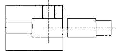
图1为轴肩与搅拌针插入式装配方式示意图;Figure 1 is a schematic diagram of the plug-in assembly method of the shaft shoulder and the stirring needle;
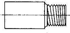
图2为轴肩与搅拌针旋入式装配方式示意图;Figure 2 is a schematic diagram of the screw-in assembly method of the shaft shoulder and the stirring needle;
图3螺线形轴肩设计结构示意;Figure 3 shows the design structure of the spiral shoulder;
图4轮辐形轴肩设计结构示意;Figure 4 Schematic diagram of the design structure of the spoke-shaped shoulder;
图5同心形轴肩设计结构示意;Figure 5 shows the design structure of the concentric shoulder;
图6涡轮形轴肩设计结构示意;Fig. 6 Schematic diagram of the design structure of the turbine-shaped shoulder;
图7蜂窝形轴肩设计结构示意;Figure 7 is a schematic diagram of the design structure of the honeycomb shoulder;
图8八卦形轴肩设计结构示意;Figure 8 Schematic diagram of the design structure of the gossip-shaped shoulder;
图9轮辐形轴肩的侧剖面图;Figure 9 is a side sectional view of a spoke-shaped shoulder;
图10同心形轴肩的侧剖面图;The side sectional view of Fig. 10 concentric shoulder;
图11典型的搅拌针结构示意;Figure 11 shows a typical structure of a stirring needle;
图12典型的搅拌针结构示意;Figure 12 shows a typical structure of a stirring needle;
图13典型的搅拌针结构示意;Figure 13 shows a typical structure of a stirring needle;
图14典型的搅拌针结构示意。Figure 14 shows a typical structure of a stirring needle.
具体实施方式:Detailed ways:
图1、2给出轴肩和搅拌针两种典型的装配方式示意图。第一种为插入式装配(图1),搅拌针通过合理的公差配合插入轴肩,进入深度由轴肩内部的凸台设计或顶丝限定,搅拌针在轴肩内部的固紧由侧面顶丝来实现。第二种为螺纹旋入式装配(图2),轴肩和搅拌针装配部分分别加工有内、外螺纹,把搅拌针旋入轴肩螺孔实现装配,搅拌针旋入深度由轴肩内部的凸台设计或顶丝限定。Figures 1 and 2 show schematic diagrams of two typical assembly methods of the shaft shoulder and the stirring needle. The first is plug-in assembly (Figure 1). The stirring needle is inserted into the shaft shoulder through a reasonable tolerance. silk to achieve. The second type is threaded screw-in assembly (Fig. 2). The shaft shoulder and stirring needle assembly part are respectively processed with internal and external threads, and the stirring needle is screwed into the screw hole of the shaft shoulder to realize assembly. Boss design or set screw limit.
轴肩的几何设计从普通的锅盔形到含有各种结构细节的特殊形,图3~8给出了几种含有结构细节的轴肩设计,图9、10为轮辐形和同心形轴肩的侧剖面图。The geometric design of the shoulders ranges from the common pot helmet shape to special shapes with various structural details. Figures 3 to 8 show several shoulder designs with structural details. Figures 9 and 10 show the spoke-shaped and concentric shoulders Side profile view.
搅拌针设计从无结构特点的柱形和锥形(包括圆形和各种多边形截面)到加工有各种螺纹的柱形和锥形设计,搅拌针表面可加工有各种凹槽或平面。图11~14给出了几种典型的搅拌针设计。The design of the stirring needle ranges from cylindrical and conical (including circular and various polygonal cross-sections) without structural features to cylindrical and conical designs with various threads. The surface of the stirring needle can be processed with various grooves or planes. Figures 11 to 14 show several typical stirring pin designs.
实施例1Example 1
采用高速钢作为工具材料,采用车、铣、钻等机加工工艺分别加工出焊接工具的轴肩和搅拌针部分,热处理到~60的HRC硬度后进行精磨成型。轴肩与搅拌针通过精密的滑动装配组合在一起,装配公差为0.01mm,通过轴肩内部的凸台设计和固紧螺钉,实现搅拌针的精确定位和固紧。这样的组合焊接工具可广泛用于焊接铝、镁、铜合金及其复合材料。当搅拌针折断或严重磨损后,取出损坏的搅拌针,更换一新的搅拌针即可恢复焊接工具的使用功能。High-speed steel is used as the tool material, and the shaft shoulder and stirring pin part of the welding tool are respectively processed by turning, milling, drilling and other machining processes, and are heat-treated to a HRC hardness of ~60 for fine grinding and forming. The shaft shoulder and the stirring needle are combined through a precise sliding assembly, and the assembly tolerance is 0.01mm. The precise positioning and fastening of the stirring needle is realized through the design of the boss inside the shaft shoulder and the fastening screw. Such a combined welding tool can be widely used for welding aluminum, magnesium, copper alloys and composite materials thereof. When the stirring needle is broken or severely worn, take out the damaged stirring needle and replace it with a new stirring needle to restore the use function of the welding tool.
比较例1Comparative example 1
采用同样的材料和机加工工艺加工出同样尺寸的整体式焊接工具,工具具有~60的同样HRC硬度,这样的焊接工具可以满足一般的焊接要求。然而,当进行低热输入焊接时,搅拌针经常折断;进行复合材料焊接时,搅拌针很容易发生磨损。当搅拌针发生折断或严重磨损后,这种整体式的焊接工具就只能报废了。The integral welding tool of the same size is processed by the same material and machining process, and the tool has the same HRC hardness of ~60. Such a welding tool can meet general welding requirements. However, the pins often break when welding with low heat input and are prone to wear when welding composite materials. When the stirring pin is broken or severely worn, this one-piece welding tool can only be scrapped.
实施例2Example 2
采用高速钢和高温合金作为原材料,采用车、铣、钻等机加工工艺分别加工出高速钢轴肩和高温合金搅拌针,高速钢的轴肩热处理到~60的HRC硬度后与高温合金搅拌针进行精磨成型。轴肩与搅拌针的装配通过螺纹来实现,并采用螺钉实现搅拌针的定位和固紧。这样的组合焊接工具主要用于焊接铜合金及其它高熔点金属材料。当高温合金搅拌针折断或严重磨损后,取出损坏的搅拌针,更换一新的搅拌针即可恢复焊接工具的使用功能。High-speed steel and high-temperature alloy are used as raw materials, and high-speed steel shoulders and high-temperature alloy stirring pins are processed by machining processes such as turning, milling, and drilling. Carry out fine grinding and shaping. The assembly of the shaft shoulder and the stirring needle is realized by threads, and the positioning and fastening of the stirring needle are realized by screws. Such combined welding tools are mainly used for welding copper alloys and other high melting point metal materials. When the high-temperature alloy stirring needle is broken or severely worn, take out the damaged stirring needle and replace it with a new stirring needle to restore the use function of the welding tool.
比较例2Comparative example 2
采用高速钢和同样机加工工艺加工出同样尺寸的整体式焊接工具,工具具有~60的同样HRC硬度,这样的焊接工具在焊接高熔点材料时热强性不足,搅拌针易于发生损坏,一旦搅拌针损坏这种整体式的焊接工具就只能报废了。Use high-speed steel and the same machining process to process integral welding tools of the same size. The tools have the same HRC hardness of ~60. Such welding tools have insufficient thermal strength when welding high-melting point materials, and the stirring needle is easy to be damaged. Once stirred If the needle damages this integral welding tool, it can only be scrapped.
比较例3Comparative example 3
采用高温合金和同样机加工工艺加工出同样尺寸的整体式焊接工具,这样的焊接工具具有很好的热强性,适用于焊接高熔点材料。然而,即使在焊接高熔点材料时,一些低热输入焊接条件也常常造成高温合金搅拌针在较低温度下的折断或磨损,搅拌针损坏后这种造价昂贵的整体式高温合金焊接工具就只能报废了。The integral welding tool of the same size is processed by the high temperature alloy and the same machining process. Such a welding tool has good thermal strength and is suitable for welding high melting point materials. However, even when welding high melting point materials, some low heat input welding conditions often cause the superalloy stirring pin to break or wear at lower temperatures. After the stirring pin is damaged, this expensive integral superalloy welding tool can only be used Scrapped.
Claims (4)
Priority Applications (1)
| Application Number | Priority Date | Filing Date | Title |
|---|---|---|---|
| CNA2006101351509ACN101209512A (en) | 2006-12-28 | 2006-12-28 | A Combined Friction Stir Welding Tool |
Applications Claiming Priority (1)
| Application Number | Priority Date | Filing Date | Title |
|---|---|---|---|
| CNA2006101351509ACN101209512A (en) | 2006-12-28 | 2006-12-28 | A Combined Friction Stir Welding Tool |
Publications (1)
| Publication Number | Publication Date |
|---|---|
| CN101209512Atrue CN101209512A (en) | 2008-07-02 |
Family
ID=39609865
Family Applications (1)
| Application Number | Title | Priority Date | Filing Date |
|---|---|---|---|
| CNA2006101351509APendingCN101209512A (en) | 2006-12-28 | 2006-12-28 | A Combined Friction Stir Welding Tool |
Country Status (1)
| Country | Link |
|---|---|
| CN (1) | CN101209512A (en) |
Cited By (28)
| Publication number | Priority date | Publication date | Assignee | Title |
|---|---|---|---|---|
| CN102581469A (en)* | 2012-03-01 | 2012-07-18 | 江苏科技大学 | Welding set for zero-inclination angle planar two-dimensional curve stir friction welding |
| CN102848069A (en)* | 2011-10-17 | 2013-01-02 | 南通天华和睿科技创业有限公司 | Stirring pin for surface stirring and rubbing |
| CN102905838A (en)* | 2010-03-24 | 2013-01-30 | 公立大学法人大阪府立大学 | Tool for friction processing, friction processing device using same, and friction processing method |
| CN103331516A (en)* | 2013-07-10 | 2013-10-02 | 大连理工大学 | Combined adjustable stir-welding head of friction stir welding |
| CN103846542A (en)* | 2012-11-29 | 2014-06-11 | 上海航天设备制造总厂 | Solid-phase welding method and device of overlap connection of aluminum materials and high melting point metal |
| CN104221069A (en)* | 2012-02-02 | 2014-12-17 | 林肯环球股份有限公司 | Virtual Welding System |
| US9330575B2 (en) | 2008-08-21 | 2016-05-03 | Lincoln Global, Inc. | Tablet-based welding simulator |
| US9468988B2 (en) | 2009-11-13 | 2016-10-18 | Lincoln Global, Inc. | Systems, methods, and apparatuses for monitoring weld quality |
| US9483959B2 (en) | 2008-08-21 | 2016-11-01 | Lincoln Global, Inc. | Welding simulator |
| US9754509B2 (en) | 2008-08-21 | 2017-09-05 | Lincoln Global, Inc. | Importing and analyzing external data using a virtual reality welding system |
| US9767712B2 (en) | 2012-07-10 | 2017-09-19 | Lincoln Global, Inc. | Virtual reality pipe welding simulator and setup |
| US9836994B2 (en) | 2009-07-10 | 2017-12-05 | Lincoln Global, Inc. | Virtual welding system |
| US9895267B2 (en) | 2009-10-13 | 2018-02-20 | Lincoln Global, Inc. | Welding helmet with integral user interface |
| US9928755B2 (en) | 2008-08-21 | 2018-03-27 | Lincoln Global, Inc. | Virtual reality GTAW and pipe welding simulator and setup |
| CN107953024A (en)* | 2017-12-22 | 2018-04-24 | 广东柳泰焊接科技有限公司 | Device for stirring head |
| US10198962B2 (en) | 2013-09-11 | 2019-02-05 | Lincoln Global, Inc. | Learning management system for a real-time simulated virtual reality welding training environment |
| US10496080B2 (en) | 2006-12-20 | 2019-12-03 | Lincoln Global, Inc. | Welding job sequencer |
| USRE47918E1 (en) | 2009-03-09 | 2020-03-31 | Lincoln Global, Inc. | System for tracking and analyzing welding activity |
| CN111438433A (en)* | 2020-04-17 | 2020-07-24 | 哈尔滨万洲焊接技术有限公司 | Method for measuring peak temperature of FSW welding seam center area and welding tool |
| CN111790978A (en)* | 2019-04-03 | 2020-10-20 | 株式会社不二越 | Friction Stir Welding Tool |
| US10878591B2 (en) | 2016-11-07 | 2020-12-29 | Lincoln Global, Inc. | Welding trainer utilizing a head up display to display simulated and real-world objects |
| US10913125B2 (en) | 2016-11-07 | 2021-02-09 | Lincoln Global, Inc. | Welding system providing visual and audio cues to a welding helmet with a display |
| US10930174B2 (en) | 2013-05-24 | 2021-02-23 | Lincoln Global, Inc. | Systems and methods providing a computerized eyewear device to aid in welding |
| US10940555B2 (en) | 2006-12-20 | 2021-03-09 | Lincoln Global, Inc. | System for a welding sequencer |
| CN112719568A (en)* | 2021-02-02 | 2021-04-30 | 铜陵学院 | Brazing friction stir welding stirring head with split type abrasive particles arranged in spiral order and machining method thereof |
| US10997872B2 (en) | 2017-06-01 | 2021-05-04 | Lincoln Global, Inc. | Spring-loaded tip assembly to support simulated shielded metal arc welding |
| US10994358B2 (en) | 2006-12-20 | 2021-05-04 | Lincoln Global, Inc. | System and method for creating or modifying a welding sequence based on non-real world weld data |
| CN114985899A (en)* | 2022-05-26 | 2022-09-02 | 南京航空航天大学 | Split type friction stir welding stirring head with quick replacement function |
- 2006
- 2006-12-28CNCNA2006101351509Apatent/CN101209512A/enactivePending
Cited By (47)
| Publication number | Priority date | Publication date | Assignee | Title |
|---|---|---|---|---|
| US10496080B2 (en) | 2006-12-20 | 2019-12-03 | Lincoln Global, Inc. | Welding job sequencer |
| US11980976B2 (en) | 2006-12-20 | 2024-05-14 | Lincoln Global, Inc. | Method for a welding sequencer |
| US10994358B2 (en) | 2006-12-20 | 2021-05-04 | Lincoln Global, Inc. | System and method for creating or modifying a welding sequence based on non-real world weld data |
| US10940555B2 (en) | 2006-12-20 | 2021-03-09 | Lincoln Global, Inc. | System for a welding sequencer |
| US9928755B2 (en) | 2008-08-21 | 2018-03-27 | Lincoln Global, Inc. | Virtual reality GTAW and pipe welding simulator and setup |
| US9818312B2 (en) | 2008-08-21 | 2017-11-14 | Lincoln Global, Inc. | Importing and analyzing external data using a virtual reality welding system |
| US12136353B2 (en) | 2008-08-21 | 2024-11-05 | Lincoln Global, Inc. | Importing and analyzing external data using a virtual reality welding system |
| US9330575B2 (en) | 2008-08-21 | 2016-05-03 | Lincoln Global, Inc. | Tablet-based welding simulator |
| US9336686B2 (en) | 2008-08-21 | 2016-05-10 | Lincoln Global, Inc. | Tablet-based welding simulator |
| US11030920B2 (en) | 2008-08-21 | 2021-06-08 | Lincoln Global, Inc. | Importing and analyzing external data using a virtual reality welding system |
| US9483959B2 (en) | 2008-08-21 | 2016-11-01 | Lincoln Global, Inc. | Welding simulator |
| US9754509B2 (en) | 2008-08-21 | 2017-09-05 | Lincoln Global, Inc. | Importing and analyzing external data using a virtual reality welding system |
| US9761153B2 (en) | 2008-08-21 | 2017-09-12 | Lincoln Global, Inc. | Importing and analyzing external data using a virtual reality welding system |
| US10803770B2 (en) | 2008-08-21 | 2020-10-13 | Lincoln Global, Inc. | Importing and analyzing external data using a virtual reality welding system |
| US9779635B2 (en) | 2008-08-21 | 2017-10-03 | Lincoln Global, Inc. | Importing and analyzing external data using a virtual reality welding system |
| US9779636B2 (en) | 2008-08-21 | 2017-10-03 | Lincoln Global, Inc. | Importing and analyzing external data using a virtual reality welding system |
| US9818311B2 (en) | 2008-08-21 | 2017-11-14 | Lincoln Global, Inc. | Importing and analyzing external data using a virtual reality welding system |
| US10762802B2 (en) | 2008-08-21 | 2020-09-01 | Lincoln Global, Inc. | Welding simulator |
| US9836995B2 (en) | 2008-08-21 | 2017-12-05 | Lincoln Global, Inc. | Importing and analyzing external data using a virtual reality welding system |
| US11521513B2 (en) | 2008-08-21 | 2022-12-06 | Lincoln Global, Inc. | Importing and analyzing external data using a virtual reality welding system |
| US9858833B2 (en) | 2008-08-21 | 2018-01-02 | Lincoln Global, Inc. | Importing and analyzing external data using a virtual reality welding system |
| US10056011B2 (en) | 2008-08-21 | 2018-08-21 | Lincoln Global, Inc. | Importing and analyzing external data using a virtual reality welding system |
| US11715388B2 (en) | 2008-08-21 | 2023-08-01 | Lincoln Global, Inc. | Importing and analyzing external data using a virtual reality welding system |
| USRE47918E1 (en) | 2009-03-09 | 2020-03-31 | Lincoln Global, Inc. | System for tracking and analyzing welding activity |
| US9836994B2 (en) | 2009-07-10 | 2017-12-05 | Lincoln Global, Inc. | Virtual welding system |
| US9895267B2 (en) | 2009-10-13 | 2018-02-20 | Lincoln Global, Inc. | Welding helmet with integral user interface |
| US9468988B2 (en) | 2009-11-13 | 2016-10-18 | Lincoln Global, Inc. | Systems, methods, and apparatuses for monitoring weld quality |
| CN102905838A (en)* | 2010-03-24 | 2013-01-30 | 公立大学法人大阪府立大学 | Tool for friction processing, friction processing device using same, and friction processing method |
| CN102848069A (en)* | 2011-10-17 | 2013-01-02 | 南通天华和睿科技创业有限公司 | Stirring pin for surface stirring and rubbing |
| CN104221069A (en)* | 2012-02-02 | 2014-12-17 | 林肯环球股份有限公司 | Virtual Welding System |
| CN102581469A (en)* | 2012-03-01 | 2012-07-18 | 江苏科技大学 | Welding set for zero-inclination angle planar two-dimensional curve stir friction welding |
| US9767712B2 (en) | 2012-07-10 | 2017-09-19 | Lincoln Global, Inc. | Virtual reality pipe welding simulator and setup |
| CN103846542A (en)* | 2012-11-29 | 2014-06-11 | 上海航天设备制造总厂 | Solid-phase welding method and device of overlap connection of aluminum materials and high melting point metal |
| US10930174B2 (en) | 2013-05-24 | 2021-02-23 | Lincoln Global, Inc. | Systems and methods providing a computerized eyewear device to aid in welding |
| CN103331516A (en)* | 2013-07-10 | 2013-10-02 | 大连理工大学 | Combined adjustable stir-welding head of friction stir welding |
| CN103331516B (en)* | 2013-07-10 | 2015-06-10 | 大连理工大学 | Combined adjustable stir-welding head of friction stir welding |
| US10198962B2 (en) | 2013-09-11 | 2019-02-05 | Lincoln Global, Inc. | Learning management system for a real-time simulated virtual reality welding training environment |
| US10878591B2 (en) | 2016-11-07 | 2020-12-29 | Lincoln Global, Inc. | Welding trainer utilizing a head up display to display simulated and real-world objects |
| US10913125B2 (en) | 2016-11-07 | 2021-02-09 | Lincoln Global, Inc. | Welding system providing visual and audio cues to a welding helmet with a display |
| US10997872B2 (en) | 2017-06-01 | 2021-05-04 | Lincoln Global, Inc. | Spring-loaded tip assembly to support simulated shielded metal arc welding |
| CN107953024A (en)* | 2017-12-22 | 2018-04-24 | 广东柳泰焊接科技有限公司 | Device for stirring head |
| CN111790978A (en)* | 2019-04-03 | 2020-10-20 | 株式会社不二越 | Friction Stir Welding Tool |
| CN111790978B (en)* | 2019-04-03 | 2024-02-20 | 株式会社不二越 | Friction stir welding tool |
| CN111438433A (en)* | 2020-04-17 | 2020-07-24 | 哈尔滨万洲焊接技术有限公司 | Method for measuring peak temperature of FSW welding seam center area and welding tool |
| CN111438433B (en)* | 2020-04-17 | 2021-09-14 | 哈尔滨万洲焊接技术有限公司 | Method for measuring peak temperature of FSW welding seam center area and welding tool |
| CN112719568A (en)* | 2021-02-02 | 2021-04-30 | 铜陵学院 | Brazing friction stir welding stirring head with split type abrasive particles arranged in spiral order and machining method thereof |
| CN114985899A (en)* | 2022-05-26 | 2022-09-02 | 南京航空航天大学 | Split type friction stir welding stirring head with quick replacement function |
Similar Documents
| Publication | Publication Date | Title |
|---|---|---|
| CN101209512A (en) | A Combined Friction Stir Welding Tool | |
| CN101176944B (en) | Friction stir welding tool and friction stir welding apparatus | |
| US7383975B2 (en) | Fracture resistant friction stir welding tools | |
| JP4298729B2 (en) | Friction stir welding tool | |
| KR102209472B1 (en) | End milling cutter for heat-resistant superalloys | |
| CN101374602B (en) | Multi-material part or component and method for its production | |
| CN105563665B (en) | Diamond-coated tools and preparation method and its application in graphite High-speed machining | |
| JP7210735B2 (en) | Tool assembly for friction stir welding | |
| CN103764333A (en) | Friction stir welding tool | |
| CN205167262U (en) | Be applied to diamond coated cutting tool among graphite high -speed machining | |
| US11986901B2 (en) | Friction stir welding tool and friction stir welding method | |
| CN101108432A (en) | Hobbing cutter and forming method thereof | |
| CN214518156U (en) | Suspended type thick plate double-shaft-shoulder friction stir welding device | |
| Sun et al. | Hole-making and its Impact on the Fatigue Response of Ti-6AL-4V Alloy | |
| CN102085599A (en) | Rubbing and stirring joint method and rubbing and stirring joint product | |
| CN104005020A (en) | Manufacturing method for radial bearing of screw drill | |
| Singh et al. | Comparison of slurry effect on machining characteristics of titanium in ultrasonic drilling | |
| US20150129638A1 (en) | Friction Stir Welding Tool and Method for the Production Thereof | |
| CN201405549Y (en) | A bimetal composite structure of powder high-speed steel and structural steel | |
| CN211135903U (en) | Semi-floating multi-shaft-shoulder stirring tool | |
| CN219254468U (en) | Friction stir spot welding stirring head capable of welding high-melting-point materials | |
| CN102049583A (en) | Method for manufacturing composite welding blade | |
| KR20080104896A (en) | End mill and its manufacturing method | |
| KR20160060450A (en) | Friction stir welding tool | |
| JP6410135B2 (en) | Hot forging die |
Legal Events
| Date | Code | Title | Description |
|---|---|---|---|
| C06 | Publication | ||
| PB01 | Publication | ||
| C10 | Entry into substantive examination | ||
| SE01 | Entry into force of request for substantive examination | ||
| C12 | Rejection of a patent application after its publication | ||
| RJ01 | Rejection of invention patent application after publication |