CN101208811A - semiconductor light emitting device - Google Patents
semiconductor light emitting deviceDownload PDFInfo
- Publication number
- CN101208811A CN101208811ACNA2006800231245ACN200680023124ACN101208811ACN 101208811 ACN101208811 ACN 101208811ACN A2006800231245 ACNA2006800231245 ACN A2006800231245ACN 200680023124 ACN200680023124 ACN 200680023124ACN 101208811 ACN101208811 ACN 101208811A
- Authority
- CN
- China
- Prior art keywords
- sealing
- semiconductor light
- sealing portion
- light
- emitting apparatus
- Prior art date
- Legal status (The legal status is an assumption and is not a legal conclusion. Google has not performed a legal analysis and makes no representation as to the accuracy of the status listed.)
- Pending
Links
Images


Landscapes
- Led Device Packages (AREA)
Abstract
Description
Translated fromChinese技术领域technical field
[0001]本发明涉及一种将LED(Light Emitting Diode:发光二极管)芯片等半导体芯片封装化而成的半导体发光装置。[0001] The present invention relates to a semiconductor light-emitting device that encapsulates semiconductor chips such as LED (Light Emitting Diode: light emitting diode) chips.
背景技术Background technique
[0002]近年来,白光LED装置已被实用化,作为取代荧光灯的照明部件备受关注。[0002] In recent years, white LED devices have been put into practical use, and have attracted attention as lighting components that replace fluorescent lamps.
[0003]人们开发出了采用氮化镓(GaN)化合物半导体的、发蓝光区到紫外光区的光的LED芯片,这促进了白光LED装置的实用化。[0003] People have developed LED chips using gallium nitride (GaN) compound semiconductors that emit light from the blue light region to the ultraviolet light region, which promotes the practical application of white light LED devices.
[0004]利用发蓝光区到紫外光区的光的LED芯片得到白光的方法,主要有两种(例如,参照非专利文献1。):第一,是利用蓝光LED芯片所放射出的蓝光、和用蓝光激发铈掺杂钇铝石榴石(YAG:Ce)等荧光材料来得到的黄光得到白光的方法;第二,是用发紫光区到紫外光区的光的LED芯片所放射的光激发多种荧光材料,得到红、绿及蓝这些所谓的三原色的光,来得到白光的方法。Y2O2S:Eu(简称为P22-RE3)被用作红光用荧光材料。ZnS:Cu,Al(简称为P22-GN4)或(Ba,Mg)Al10O17:Eu,Mn(简称为LP-G3)被用作绿光用荧光材料。(Sr,Ca,Ba,Mg)10(PO4)6C12:Eu(简称为LP-B1)或(Ba,Mg)Al10O17:Eu(简称为LP-B4)被用作蓝光用荧光材料。The method that utilizes the LED chip that sends out the light of blue light region to the light of ultraviolet light region to obtain white light mainly contains two kinds (for example, with reference to
[0005]白光LED装置,是通过用密封用树脂材料将发蓝光区到紫外光区的光的LED芯片和所述荧光材料封装化来实现的。作为代表性封装方式,有将密封用树脂材料形成为炮弹型的结构(例如,参照非专利文献2。)。[0005] The white light LED device is realized by encapsulating the LED chip emitting light from the blue light region to the ultraviolet light region and the fluorescent material with a resin material for sealing. As a typical encapsulation method, there is a structure in which a sealing resin material is formed into a cannonball shape (see, for example, Non-Patent
[0006]下面,参照图45,对具有炮弹型封装形状的现有白光LED装置进行说明。[0006] Next, with reference to FIG. 45, a description will be given of a conventional white LED device having a cannonball-shaped package shape.
[0007]如图45所示,在现有例所涉及的白光LED装置100中,发蓝光区到紫外光区的光的LED芯片102通过糊(paste)状银材料或糊状绝缘材料等芯片固定用糊状材料103固定在芯片垫(die pad)部的底面上,该芯片垫设置在第一引线框101A的一个端部并呈碗状。As shown in FIG. 45, in the white
[0008]在LED芯片102的上表面上,形成有第一电极104A和第二电极104B。第一电极104A,通过第一金属线105A与第一引线框101A电连接,第二电极104B通过第二金属线105B与和第一引线框101A配成对的第二引线框101B电连接。[0008] On the upper surface of the
[0009]LED芯片102,被成形为炮弹状的树脂材料105密封。一般用环氧树脂或硅树脂等对可见光透明的树脂材料作为树脂材料105。在树脂材料105中,混合有所述荧光材料106(例如,参照专利文献1)。[0009] The
非专利文献1:只友一行及其他著《三菱电线工业时报》第99号、2002年7月、第35到第41页Non-Patent Document 1: "Mitsubishi Electric Wire Industry Times" No. 99, July 2002, pages 35 to 41 by Yuki and his colleagues
非专利文献2:杉本胜及其他著《松下电工技报》第53号、No.1、第4到第9页Non-Patent Document 2: Masaru Sugimoto and others, "Matsushita Electric Technical Bulletin" No. 53, No. 1, pages 4 to 9
专利文献1:日本公开专利公报特开2004-71908号公报Patent Document 1: Japanese Laid-Open Patent Publication No. 2004-71908
专利文献2:日本公开专利公报特开2005-93724号公报Patent Document 2: Japanese Laid-Open Patent Publication No. 2005-93724
[0010]然而,在对上述现有白光LED装置100采用环氧树脂或硅树脂作为密封用树脂材料105的情况下,会出现下述问题。[0010] However, in the case where epoxy resin or silicone resin is used as the sealing
[0011]在采用环氧树脂的情况下,会有环氧树脂变为黄色的问题。就是说,由LED芯片102放射出的、蓝光区到紫外光区的光使环氧树脂变成黄色,使得白光LED装置100所发的发光亮度会减低,色调会变化。鉴于此,密封用树脂材料105需要有耐光性和耐热性。[0011] In the case of using an epoxy resin, there is a problem that the epoxy resin turns yellow. That is to say, the light from the blue light range to the ultraviolet light range emitted by the
[0012]在芯片固定用糊状材料103由树脂构成的情况下,LED芯片102所放射的光会使芯片固定用糊状材料103变色,使得发光亮度会减低,光强度会恶化。这也是一个问题。[0012] When the
[0013]而且,从外部入射的、紫外光区的光也会使构成半导体发光装置的树脂材料105及荧光材料106恶化,甚至还会使由树脂构成的芯片固定用糊状材料103恶化。这也是一个问题。[0013] Moreover, incident light from the outside in the ultraviolet region will also deteriorate the
[0014]另一方面,硅树脂有下述问题,即:因为与环氧树脂相比,硅树脂的的光折射率更低,所以LED芯片102所放射的光容易发生全反射,使得从LED芯片102提取的光提取效率较低(例如,参照专利文献2。)。[0014] On the other hand, the silicone resin has the following problem, that is, because the light refractive index of the silicone resin is lower than that of the epoxy resin, the light emitted by the
[0015]补充说明一下,因为和LED芯片(特别是氮化镓半导体)的折射率比较起来,环氧树脂的折射率非常低,所以即使在使用环氧树脂的情况下,也不应该算是光提取效率足够高。[0015] As an additional explanation, because the refractive index of epoxy resin is very low compared with the refractive index of LED chip (especially gallium nitride semiconductor), so even in the case of using epoxy resin, it should not be regarded as a light source. The extraction efficiency is high enough.
[0016]不仅仅是发出发光波长在蓝光区到紫外光区的光的LED芯片,发光波长比蓝光长的LED芯片也不应该算是光提取效率足够高。[0016] Not only LED chips emitting light with a light emission wavelength in the blue light region to the ultraviolet light region, LED chips with light emission wavelengths longer than blue light should not be regarded as having a high enough light extraction efficiency.
发明内容Contents of the invention
[0017]本发明,正是为解决所述问题而研究开发出来的。其目的在于:谋求对形成有发光元件的半导体芯片进行密封的密封材料的耐光性、耐热性及光提取效率的提高。[0017] The present invention has been researched and developed to solve the problem. Its purpose is to improve the light resistance, heat resistance, and light extraction efficiency of a sealing material that seals a semiconductor chip on which a light emitting element is formed.
[0018]为了达成上述目的,在本发明中设为下述结构,即:使构成半导体发光装置的密封部的基体材料包含由无机材料构成的、有效粒径在发光波长的四分之一以下的粒子。In order to achieve the above-mentioned object, be set as following structure in the present invention, promptly: make the matrix material that forms the sealing portion of semiconductor light-emitting device comprise to comprise by inorganic material, effective particle diameter is below 1/4 of light-emitting wavelength particle of.
[0019]具体而言,本发明所涉及的第一半导体发光装置,包括放出波长在蓝光区到紫外光区的光的半导体芯片,和形成在光所通过的通过路径上的至少一部分区域中的密封部;密封部包含密封材料和荧光材料,该密封材料由包含基体材料和粒子的复合材料构成,所述粒子由无机材料构成,已分散在该基体材料中,所述粒子的有效粒径在基体材料内部的光的波长的四分之一以下。Specifically, the first semiconductor light-emitting device involved in the present invention includes a semiconductor chip that emits light with a wavelength in the blue light region to the ultraviolet light region, and is formed in at least a part of the area on the passing path through which the light passes. A sealing part; the sealing part comprises a sealing material and a fluorescent material, and the sealing material is composed of a composite material comprising a matrix material and particles, the particles are composed of inorganic materials dispersed in the matrix material, and the effective particle diameter of the particles is between Less than a quarter of the wavelength of light inside the matrix material.
[0020]根据第一半导体发光装置,因为已分散在密封部的基体材料中的粒子由无机材料构成,所以与不包含所述由无机材料构成的粒子的情况相比密封部的耐光性和耐热性有所提高。而且,因为已分散在基体材料中的粒子的有效粒径在半导体芯片所放射的光的波长的四分之一以下,所以不会损害密封部的透明性,就是说不会对光提取效率造成不良影响。补充说明一下,若粒子的大小充分地小于光的波长,就可以将分散有无机粒子的复合材料看作没有折射率偏差的、均一的介质。若粒子的直径在光的波长的四分之一以下,复合材料中的光的散射就只有瑞利散射,因而很少出现透光性恶化的情况。[0020] According to the first semiconductor light-emitting device, since the particles dispersed in the matrix material of the sealing portion are composed of inorganic materials, the light resistance and resistance of the sealing portion are compared with the case where the particles composed of inorganic materials are not included. Heat has been improved. Moreover, because the effective particle size of the particles dispersed in the matrix material is below a quarter of the wavelength of light emitted by the semiconductor chip, the transparency of the sealing portion will not be damaged, that is to say, the light extraction efficiency will not be affected. adverse effects. In addition, if the size of the particles is sufficiently smaller than the wavelength of light, the composite material in which the inorganic particles are dispersed can be regarded as a homogeneous medium without deviation in the refractive index. If the diameter of the particle is less than a quarter of the wavelength of light, the scattering of light in the composite material is only Rayleigh scattering, so the light transmission is rarely deteriorated.
[0021]最好是这样的,在第一半导体发光装置中,密封部形成为覆盖半导体芯片的周围。[0021] Preferably, in the first semiconductor light emitting device, the sealing portion is formed to cover the periphery of the semiconductor chip.
[0022]这样,密封部的机械强度就很大,耐热性也有所提高,不易产生密封部的剥离和裂缝。[0022] In this way, the mechanical strength of the sealing portion is very high, and the heat resistance is also improved, so that peeling and cracking of the sealing portion are not easy to occur.
[0023]最好是这样的,在第一半导体发光装置中,密封部形成为与半导体芯片相接触。[0023] Preferably, in the first semiconductor light emitting device, the sealing portion is formed in contact with the semiconductor chip.
[0024]在密封部和半导体芯片如上所述接触的情况下,与使密封部的基体材料不包含粒子的结构相比密封部及半导体芯片相互间的热膨胀系数之差更小,因此密封部也不易产生剥离及裂缝。In the case where the sealing portion and the semiconductor chip are in contact as described above, the difference in coefficient of thermal expansion between the sealing portion and the semiconductor chip is smaller than that in which the base material of the sealing portion does not contain particles, so the sealing portion is also Not easy to peel off and crack.
[0025]最好是这样的,在第一半导体发光装置中,密封部由第一密封部和第二密封部构成,该第一密封部由密封材料构成;该第二密封部形成在该第一密封部的外侧,包含荧光材料。[0025] Preferably, in the first semiconductor light-emitting device, the sealing portion is composed of a first sealing portion and a second sealing portion, the first sealing portion is composed of a sealing material; the second sealing portion is formed on the first sealing portion The outer side of a sealing part contains fluorescent material.
[0026]如上所述,通过将由为复合材料的密封材料构成的第一密封部配置在离半导体芯片较近而因此光密度较高的部分,能够实现从半导体芯片提取的、很高的光提取效率,并能够得到很强的耐光性和耐热性。而且,通过将透明性强于复合材料并且包含荧光材料的第二密封部配置在离半导体芯片较远而因此光密度较低的部分,能够提高第二密封部的透光性。其结果是,能够提高从半导体发光装置提取的光提取效率。[0026] As described above, by arranging the first sealing portion made of a sealing material that is a composite material at a portion that is closer to the semiconductor chip and thus has a higher optical density, it is possible to realize high light extraction from the semiconductor chip. Efficiency, and can get strong light fastness and heat resistance. Furthermore, the light transmittance of the second sealing portion can be improved by arranging the second sealing portion that is more transparent than the composite material and includes a fluorescent material in a portion that is farther from the semiconductor chip and thus has a lower optical density. As a result, the light extraction efficiency from the semiconductor light emitting device can be improved.
[0027]最好是这样的,在第一密封部由复合材料构成的情况下,所述半导体发光装置还包括设置在第一密封部中的半导体芯片的至少下方及侧边、让光反射的反射部件。[0027] Preferably, in the case where the first sealing portion is made of a composite material, the semiconductor light-emitting device further includes at least the bottom and sides of the semiconductor chip arranged in the first sealing portion, allowing light reflection reflective parts.
[0028]这样,含在构成位于半导体芯片一侧的第一密封部的复合材料中的粒子就如下所述使蓝光区到紫外光区的光谱衰减,红光区等短波长一侧的光谱相对地增大。在本说明书中,将该现象称为过滤效应。通过利用过滤效应,平均演色性指数(Ra)升高,能够降低色温。In this way, the particles contained in the composite material constituting the first sealing portion on the side of the semiconductor chip attenuate the spectrum from the blue light region to the ultraviolet light region as described below, and the spectra on the short wavelength side such as the red light region are relatively to increase. In this specification, this phenomenon is referred to as a filtering effect. By utilizing the filtering effect, the average color rendering index (Ra) is increased, and the color temperature can be lowered.
[0029]再说,在该情况下,最好是这样的,密封材料是用具有透明性的糊状材料固定着半导体芯片、并且被反射部件支撑着的底层(underlyinglayer)。[0029] Furthermore, in this case, it is preferable that the sealing material is an underlying layer in which the semiconductor chip is fixed with a transparent paste material and supported by the reflective member.
[0030]如上所述,因为固定半导体芯片的糊状材料是透明的,所以即使将复合材料用作底层,平均演色性指数(Ra)由于含在底层中的粒子所带来的过滤效应也升高,并能够降低色温。[0030] As described above, since the paste material for fixing the semiconductor chip is transparent, even if a composite material is used as the bottom layer, the average color rendering index (Ra) increases due to the filtering effect of the particles contained in the bottom layer. High, and can lower the color temperature.
[0031]最好是这样的,在第一半导体发光装置中,密封部由第一密封部和第二密封部构成,该第一密封部由密封材料构成;该第二密封部形成在该第一密封部的外侧。粒子由吸收紫外光区的光的材料构成。[0031] Preferably, in the first semiconductor light emitting device, the sealing portion is composed of a first sealing portion and a second sealing portion, the first sealing portion is composed of a sealing material; the second sealing portion is formed on the first sealing portion an outer side of the sealing portion. The particles are composed of materials that absorb light in the ultraviolet region.
[0032]这样,就能通过含在构成第一密封部的复合材料中的、吸收紫外光区的光的粒子来抑制紫外光使由树脂等构成的密封材料恶化的现象。[0032] In this way, the deterioration of the sealing material made of resin or the like by ultraviolet light can be suppressed by the particles contained in the composite material constituting the first sealing portion that absorb light in the ultraviolet region.
[0033]最好是这样的,在第一半导体发光装置中,密封部由第一密封部和第二密封部构成,该第一密封部包含荧光材料;该第二密封部形成在该第一密封部的外侧,由密封材料构成。[0033] Preferably, in the first semiconductor light emitting device, the sealing portion is composed of a first sealing portion and a second sealing portion, the first sealing portion contains a fluorescent material; the second sealing portion is formed on the first The outside of the sealing portion is made of a sealing material.
[0034]这样,构成形成在第一密封部的外侧的第二密封部的复合材料所包含的粒子使蓝光区到紫外光区的光谱衰减,能够得到红光区等短波长一侧的光谱相对地增大的过滤效应。这样,就能够提高平均演色性指数(Ra),并降低色温。In this way, the particles contained in the composite material forming the second sealing portion formed on the outside of the first sealing portion attenuate the spectrum from the blue light region to the ultraviolet light region, and can obtain relatively short-wavelength spectra such as the red light region. Greatly increased filtering effect. In this way, the average color rendering index (Ra) can be increased and the color temperature can be lowered.
[0035]本发明所涉及的第二半导体发光装置,包括放出光的半导体芯片,和形成在光所通过的通过路径上的至少一部分区域中的密封部。密封部包含由包含基体材料和粒子的复合材料构成的密封材料,所述粒子由无机材料构成,已分散在该基体材料中,所述粒子的有效粒径在基体材料内部的光的波长的四分之一以下,并且,所述密封部由覆盖半导体芯片的第一密封部和形成在该第一密封部的外侧的第二密封部构成。第一密封部的、根据光的波长决定的第一折射率,高于第二密封部的、根据光的波长决定的第二折射率。[0035] A second semiconductor light-emitting device according to the present invention includes a semiconductor chip that emits light, and a sealing portion formed in at least a part of an area along a path through which the light passes. The sealing portion includes a sealing material composed of a composite material including a matrix material and particles, the particles being composed of an inorganic material, dispersed in the matrix material, and the effective particle diameter of the particles is four times the wavelength of light inside the matrix material. In addition, the sealing portion is composed of a first sealing portion covering the semiconductor chip and a second sealing portion formed outside the first sealing portion. The first refractive index of the first sealing portion determined according to the wavelength of light is higher than the second refractive index of the second sealing portion determined according to the wavelength of light.
[0036]根据第二半导体发光装置,因为与第一半导体发光装置一样,密封部包含由无机材料构成、已分散在基体材料中、并且有效粒径在基体材料内部的光的波长的四分之一以下的粒子,所以密封部的耐光性和耐热性提高,并且不会对密封部的透明性造成不良影响。而且,因为第一密封部的根据光的波长决定的第一折射率高于第二密封部的根据光的波长决定的第二折射率,所以整个密封部的折射率在位于半导体芯片一侧的内侧区域较高,并且在位于该内侧区域的外侧的外侧区域较低。因此,外侧区域的折射率较低,使得半导体芯片所出射的出射光的全反射减低,结果光提取效率提高。[0036] According to the second semiconductor light-emitting device, because, like the first semiconductor light-emitting device, the sealing portion contains a quarter of the wavelength of light that is composed of an inorganic material, dispersed in the matrix material, and has an effective particle diameter inside the
[0037]最好是这样的,在第二半导体发光装置中,含在第一密封部中的粒子的组成和含在第二密封部中的粒子的组成不同。[0037] Preferably, in the second semiconductor light emitting device, the composition of the particles contained in the first sealing portion is different from the composition of the particles contained in the second sealing portion.
[0038]这样,例如通过使第一密封部包含具有折射率高于含在第二密封部中的粒子的折射率的组成的粒子,就能够确实地使第一密封部的折射率高于第二密封部的折射率。[0038] Thus, for example, by making the first sealing portion contain particles having a composition having a refractive index higher than that of particles contained in the second sealing portion, the refractive index of the first sealing portion can be reliably made higher than that of the second sealing portion. Second, the refractive index of the sealing part.
[0039]最好是这样的,在第二半导体发光装置中,第一密封部中的粒子在复合材料中所占的比例,高于第二密封部中的粒子在复合材料中所占的比例。[0039] Preferably, in the second semiconductor light-emitting device, the proportion of the particles in the first sealing portion in the composite material is higher than the proportion of the particles in the second sealing portion in the composite material .
[0040]这样,就能够确实地使第一密封部的折射率高于第二密封部的折射率。[0040] In this way, it is possible to surely make the refractive index of the first sealing portion higher than the refractive index of the second sealing portion.
[0041]本发明所涉及的第三半导体发光装置,包括放出光的半导体芯片,和形成在光所通过的通过路径上的至少一部分区域中的密封部。密封部包含由包含基体材料和粒子的复合材料构成的密封材料,所述粒子由无机材料构成,已分散在该基体材料中,所述粒子的有效粒径在基体材料内部的光的波长的四分之一以下,并且,根据光的波长决定的折射率设定为从离半导体芯片近的内侧区域向外侧区域逐渐变低。[0041] A third semiconductor light-emitting device according to the present invention includes a semiconductor chip that emits light, and a sealing portion formed in at least a partial region of a passage path through which the light passes. The sealing portion includes a sealing material composed of a composite material including a matrix material and particles, the particles being composed of an inorganic material, dispersed in the matrix material, and the effective particle diameter of the particles is four times the wavelength of light inside the matrix material. In addition, the refractive index determined according to the wavelength of light is set to gradually decrease from the inner region closer to the semiconductor chip to the outer region.
[0042]根据第三半导体发光装置,因为与第一半导体发光装置一样,密封部包含由无机材料构成、已分散在基体材料中、并且有效粒径在基体材料内部的光的波长的四分之一以下的粒子,所以密封部的耐光性和耐热性提高,并且不会对密封部的透明性造成不良影响。而且,因为根据光的波长决定的折射率设定为从离半导体芯片近的内侧区域向外侧区域逐渐变低,所以整个密封部的折射率在位于半导体芯片一侧的内侧区域较高,并且在位于该内侧区域的外侧的外侧区域较低。因此,外侧区域的折射率较低,使得半导体芯片所出射的出射光的全反射减低,结果光提取效率提高。[0042] According to the third semiconductor light-emitting device, because, like the first semiconductor light-emitting device, the sealing portion contains a quarter of the wavelength of light that is composed of an inorganic material, dispersed in the matrix material, and has an effective particle diameter inside the
[0043]最好是这样的,在第三半导体发光装置中,在密封部中,离半导体芯片较近的内侧区域中的粒子在复合材料中所占的比例高于处在该内侧区域的外侧的外侧区域中的所述粒子在复合材料中所占的比例。[0043] Preferably, in the third semiconductor light-emitting device, in the sealing portion, the proportion of particles in the composite material in the inner region closer to the semiconductor chip is higher than that in the outer region of the inner region The proportion of the particles in the outer region of the composite material.
[0044]这样,就能够确实地使密封部中的内侧区域的折射率高于外侧区域的折射率。[0044] In this way, the refractive index of the inner region of the sealing portion can be reliably made higher than the refractive index of the outer region.
[0045]最好是这样的,在第三半导体发光装置中,在含在密封部中的粒子中,含在密封部的内侧的粒子的组成、和含在密封部的外侧的粒子的组成不同。[0045] Preferably, in the third semiconductor light-emitting device, among the particles contained in the sealing portion, the composition of the particles contained inside the sealing portion is different from the composition of the particles contained outside the sealing portion. .
[0046]这样,例如通过使密封部的内侧区域包含具有折射率高于含在密封部的外侧区域中的粒子的折射率的组成的粒子,就能够确实地使密封部中的内侧区域的折射率高于外侧区域的折射率。In this way, for example, by making the inner region of the sealing part contain particles having a composition having a refractive index higher than that of the particles contained in the outer region of the sealing part, the refractive index of the inner region in the sealing part can be reliably made The index of refraction is higher than that of the outer region.
[0047]本发明所涉及的第四半导体发光装置,包括放出光的半导体芯片,和形成在光所通过的通过路径上的至少一部分区域中的密封部。密封部包含由包含基体材料和粒子的复合材料构成的密封材料,所述粒子由无机材料构成,已分散在该基体材料中,所述粒子的有效粒径在基体材料内部的光的波长的四分之一以下,并且,密封部由覆盖半导体芯片的第一密封部和形成在该第一密封部的外侧的第二密封部构成。第二密封部,包含用来作为粒子的、由吸收紫外光区的光的材料构成的粒子。[0047] A fourth semiconductor light-emitting device according to the present invention includes a semiconductor chip that emits light, and a sealing portion formed in at least a part of an area along a path through which the light passes. The sealing portion includes a sealing material composed of a composite material including a matrix material and particles, the particles being composed of an inorganic material, dispersed in the matrix material, and the effective particle diameter of the particles is four times the wavelength of light inside the matrix material. In addition, the sealing portion is composed of a first sealing portion covering the semiconductor chip and a second sealing portion formed outside the first sealing portion. The second sealing part contains particles made of a material that absorbs light in the ultraviolet region as particles.
[0048]根据第四半导体发光装置,因为第二密封部包含用来作为所述粒子的、由吸收紫外光区的光的材料构成的粒子,所以能够在半导体芯片所放出的光包含紫外光区的波长成分的情况下抑制不需要的紫外光被放出。此外,也能够使添加在第二密封部中的粒子吸收从外部入射的紫外光,因此能够防止密封材料等的恶化。[0048] According to the fourth semiconductor light-emitting device, since the second sealing portion contains particles that are used as the particles and are composed of a material that absorbs light in the ultraviolet region, it is possible to emit light in the semiconductor chip that includes the ultraviolet region. Unnecessary ultraviolet light is suppressed from being emitted in the case of the wavelength component. In addition, the particles added to the second sealing portion can also absorb ultraviolet light incident from the outside, so that deterioration of the sealing material and the like can be prevented.
[0049]最好是这样的,在第四半导体发光装置中,第二密封部形成为:覆盖半导体芯片的上方、下方及侧边。[0049] Preferably, in the fourth semiconductor light emitting device, the second sealing portion is formed to cover the upper side, the lower side and the side of the semiconductor chip.
[0050]第五半导体发光装置,包括放出波长在蓝光区到紫外光区的光的半导体芯片,形成在光所通过的通过路径上的至少一部分区域中的密封部,支撑半导体芯片的支撑部件,以及固定半导体芯片和支撑部件的、具有透明性的糊状材料。糊状材料由包含基体材料和粒子的复合材料构成,所述粒子由无机材料构成,已分散在该基体材料中,所述粒子的有效粒径在基体材料内部的光的波长的四分之一以下。粒子由吸收紫外光区的光的材料构成。The fifth semiconductor light-emitting device, including a semiconductor chip that emits light with a wavelength in the blue light region to the ultraviolet light region, a sealing portion formed in at least a part of the area on the passing path through which the light passes, and a support member that supports the semiconductor chip, And transparent paste materials for fixing semiconductor chips and supporting parts. The pasty material consists of a composite material comprising a matrix material and particles, composed of inorganic material, dispersed in the matrix material, the particles having an effective particle size of one quarter of the wavelength of light inside the matrix material the following. The particles are composed of materials that absorb light in the ultraviolet region.
[0051]根据第五半导体发光装置,因为固定半导体芯片和支撑部件的、具有透明性的糊状材料由包含无机材料所构成的粒子的复合材料构成,所述粒子由吸收紫外光区的光的材料构成,所以能够抑制糊状材料由于紫外光的影响而恶化并变色,使得发光亮度减低的现象。因为糊状材料是透明的,所以能够将半导体芯片所放出的光透过糊状材料输出到外部。因此,光提取效率提高。此外,半导体芯片所产生的热向支撑部件放热的放热性,通过由复合材料构成的糊状材料提高。[0051] According to the fifth semiconductor light-emitting device, since the transparent pasty material for fixing the semiconductor chip and the supporting member is composed of a composite material containing particles composed of inorganic materials, the particles are composed of particles that absorb light in the ultraviolet region. Material composition, so it can prevent the pasty material from deteriorating and discoloring due to the influence of ultraviolet light, so that the phenomenon that the luminous brightness is reduced. Since the paste material is transparent, light emitted from the semiconductor chip can be transmitted to the outside through the paste material. Therefore, light extraction efficiency improves. In addition, the heat dissipation of the heat generated by the semiconductor chip to the support member is improved by the paste material made of the composite material.
[0052]最好是这样的,在第二或第三半导体发光装置中,密封部包含荧光材料。[0052] Preferably, in the second or third semiconductor light emitting device, the sealing portion contains a fluorescent material.
[0053]这样,就能在半导体芯片所出射的出射光是蓝光区或紫外光区的光的情况下激发荧光材料,得到白光。[0053] In this way, the fluorescent material can be excited to obtain white light when the outgoing light emitted by the semiconductor chip is light in the blue light region or the ultraviolet light region.
[0054]最好是这样的,在第一到第三半导体发光装置中,粒子由无机化合物构成。[0054] Preferably, in the first to third semiconductor light-emitting devices, the particles are composed of an inorganic compound.
[0055]这样,就能够增加可以选择的、用来提高耐光性、耐热性或机械强度的材料的种类。[0055] In this way, it is possible to increase the types of materials that can be selected to improve light resistance, heat resistance, or mechanical strength.
[0056]最好是这样的,在第一到第三半导体发光装置中,基体材料由树脂材料构成。[0056] Preferably, in the first to third semiconductor light emitting devices, the base material is composed of a resin material.
[0057]这样,密封部的成形性就提高。[0057] Thus, the formability of the sealing portion is improved.
[0058]在该情况下,树脂材料最好是无机高分子材料。这样,就能容易地提高耐光性和耐热性。[0058] In this case, the resin material is preferably an inorganic polymer material. Thus, light resistance and heat resistance can be easily improved.
[0059]或者,在该情况下,树脂材料最好是有机高分子材料。这样,就能够容易地提高成形性。[0059] Alternatively, in this case, the resin material is preferably an organic polymer material. In this way, formability can be easily improved.
[0060]最好是这样的,在第一到第三半导体发光装置中,基体材料由对可见光透明的材料构成。[0060] Preferably, in the first to third semiconductor light emitting devices, the base material is composed of a material transparent to visible light.
[0061]这样,密封部的透明性就进一步提高。因此,光提取效率进一步提高。[0061] Thus, the transparency of the sealing portion is further improved. Therefore, light extraction efficiency is further improved.
[0062]最好是这样的,在第一到第三半导体发光装置中,复合材料是对可见光透明的。[0062] Preferably, in the first to third semiconductor light emitting devices, the composite material is transparent to visible light.
[0063]这样,密封部的透明性就进一步提高。因此,光提取效率进一步提高。[0063] Thus, the transparency of the sealing portion is further improved. Therefore, light extraction efficiency is further improved.
[0064]最好是这样的,在第一到第三半导体发光装置中,粒子的根据光的波长决定的折射率,高于基体材料的根据光的波长决定的折射率,并且与半导体芯片的折射率相等或在该半导体芯片的折射率以下。[0064] Preferably, in the first to third semiconductor light-emitting devices, the particles have a refractive index determined according to the wavelength of light that is higher than the refractive index of the base material determined according to the wavelength of light, and is compatible with that of the semiconductor chip. The refractive index is equal to or lower than that of the semiconductor chip.
[0065]这样,就与未添加粒子的情况相比密封部的折射率更高,因而光提取效率进一步提高。[0065] In this way, the refractive index of the sealing portion is higher than that in the case where no particles are added, so that the light extraction efficiency is further improved.
[0066]最好是这样的,在第一到第三半导体发光装置中,粒子在复合材料中所占的体积百分比在5%以上且60%以下。[0066] Preferably, in the first to third semiconductor light-emitting devices, the volume percentage of the particles in the composite material is not less than 5% and not more than 60%.
[0067]这样,就能够在充分地确保复合材料的透明性的状态下提高该复合材料的耐光性和耐热性。补充说明一下,更好的是粒子在复合材料中所占的体积百分比在10%以上且50%以下,比上述两者更好的是粒子在复合材料中所占的体积百分比在20%以上且40%以下。[0067] In this way, the light resistance and heat resistance of the composite material can be improved while sufficiently ensuring the transparency of the composite material. As an additional note, it is better that the volume percentage of the particles in the composite material is more than 10% and less than 50%, and it is better than the above two that the volume percentage of the particles in the composite material is more than 20% and 40% or less.
[0068]最好是这样的,在第一或第三半导体发光装置中,密封部的外形呈半球状。[0068] Preferably, in the first or third semiconductor light emitting device, the outer shape of the sealing portion is hemispherical.
[0069]这样,就能够提高抑制半导体芯片所出射的出射光所造成的全反射的效果。[0069] In this way, the effect of suppressing the total reflection caused by the outgoing light emitted by the semiconductor chip can be enhanced.
[0070]最好是这样的,在第一或第三半导体发光装置中,密封部的剖面外形呈四角形。[0070] Preferably, in the first or third semiconductor light-emitting device, the cross-sectional shape of the sealing portion is quadrangular.
[0071]这样,就能够利用印刷法等涂上由复合材料构成的密封材料,能够容易地进行形成。而且,因为上表面由平面构成,所以能够容易地用作器件。[0071] In this way, a sealing material made of a composite material can be applied by printing or the like, and can be easily formed. Also, since the upper surface is composed of a plane, it can be easily used as a device.
[0072]最好是这样的,在第一半导体发光装置具有第一密封部和第二密封部的情况下、或在第三半导体发光装置中,第一密封部和第二密封部的外形呈半球状。[0072] Preferably, in the case where the first semiconductor light emitting device has the first sealing portion and the second sealing portion, or in the third semiconductor light emitting device, the outer shapes of the first sealing portion and the second sealing portion are Hemispherical.
[0073]最好是这样的,在第一半导体发光装置具有第一密封部和第二密封部的情况下、或在第三半导体发光装置中,第一密封部的剖面外形呈四角形,第二密封部的外形呈半球状。[0073] Preferably, in the case where the first semiconductor light emitting device has a first sealing portion and a second sealing portion, or in the third semiconductor light emitting device, the cross-sectional shape of the first sealing portion is quadrangular, and the second sealing portion The outer shape of the sealing part is hemispherical.
[0074]最好是这样的,在第一半导体发光装置具有第一密封部和第二密封部的情况下、或在第三半导体发光装置中,第一密封部和第二密封部的剖面外形呈四角形。[0074] Preferably, in the case where the first semiconductor light emitting device has the first sealing portion and the second sealing portion, or in the third semiconductor light emitting device, the cross-sectional shape of the first sealing portion and the second sealing portion It is quadrangular.
[0075]最好是这样的,在第一半导体发光装置具有第一密封部和第二密封部的情况下、或在第三半导体发光装置中,第一密封部的外形呈半球状,第二密封部的剖面外形呈四角形。[0075] Preferably, in the case where the first semiconductor light emitting device has a first sealing portion and a second sealing portion, or in the third semiconductor light emitting device, the first sealing portion has a hemispherical shape, and the second sealing portion The cross-sectional shape of the sealing portion is quadrangular.
[0076]最好是这样的,第一到第三半导体发光装置还包括:设置在密封部中的半导体芯片的侧边的区域中、让光反射的反射部件。[0076] It is preferable that the first to third semiconductor light-emitting devices further include: a reflective member provided in a region of a side of the semiconductor chip in the sealing portion to reflect light.
[0077]这样,光提取效率进一步提高。[0077] In this way, the light extraction efficiency is further improved.
[0078]最好是这样的,在该情况下,密封部的剖面形状呈下边窄而上边宽的倒锥形。[0078] It is preferable that in this case, the cross-sectional shape of the sealing portion is an inverted tapered shape with a narrow bottom and a wide top.
-发明的效果--The effect of the invention-
[0079]根据本发明的半导体发光装置,能够实现使用寿命长且亮度高的白光LED等半导体发光装置。[0079] According to the semiconductor light emitting device of the present invention, it is possible to realize a semiconductor light emitting device such as a white LED having a long service life and high brightness.
附图说明Description of drawings
[0080]图1是示意的剖面图,表示本发明的第一实施例所涉及的半导体发光装置。1 is a schematic cross-sectional view showing a semiconductor light emitting device according to a first embodiment of the present invention.
图2是剖面图,放大而表示本发明的第一实施例所涉及的半导体发光装置中的密封部。FIG. 2 is a cross-sectional view showing enlargedly a sealing portion in the semiconductor light emitting device according to the first embodiment of the present invention.
图3是图表,用来说明对第一实施例所涉及的半导体发光装置中的密封部添加的微粒的有效粒径。FIG. 3 is a graph illustrating the effective particle diameters of particles added to the sealing portion of the semiconductor light emitting device according to the first embodiment.
图4是图表,表示本发明的第一实施例所涉及的半导体发光装置中的密封部(复合材料)的折射率与微粒添加量(体积比)之间的关系。4 is a graph showing the relationship between the refractive index of the sealing portion (composite material) and the amount of fine particles added (volume ratio) in the semiconductor light emitting device according to the first embodiment of the present invention.
图5是示意的剖面图,表示本发明的第二实施例所涉及的半导体发光装置。5 is a schematic cross-sectional view showing a semiconductor light emitting device according to a second embodiment of the present invention.
图6是示意的剖面图,表示本发明的第三实施例所涉及的半导体发光装置。6 is a schematic cross-sectional view showing a semiconductor light emitting device according to a third embodiment of the present invention.
图7是示意的剖面图,表示本发明的第四实施例所涉及的半导体发光装置。7 is a schematic cross-sectional view showing a semiconductor light emitting device according to a fourth embodiment of the present invention.
图8是示意的剖面图,表示本发明的第五实施例所涉及的半导体发光装置。8 is a schematic cross-sectional view showing a semiconductor light emitting device according to a fifth embodiment of the present invention.
图9(a)是为每种构成本发明的第五实施例所涉及的半导体发光装置中的LED芯片的衬底的材料通过模拟试验求出密封部的折射率与出射光的总光通量的变化率之间的关系而做的图表;图9(b)是为每种构成本发明的第五实施例所涉及的半导体发光装置中的LED芯片的衬底的材料通过模拟试验求出密封部的折射率与总光通量之间的关系而做的图表。Fig. 9(a) shows the changes in the refractive index of the sealing portion and the total luminous flux of outgoing light obtained through simulation tests for each material constituting the substrate of the LED chip in the semiconductor light emitting device according to the fifth embodiment of the present invention. Figure 9(b) is a graph of the relationship between the ratios; Fig. 9 (b) is for each material that constitutes the substrate of the LED chip in the semiconductor light emitting device related to the fifth embodiment of the present invention through a simulation test to obtain the sealing portion. A graph of the relationship between the refractive index and the total luminous flux.
图10是示意的剖面图,表示本发明的第六实施例所涉及的半导体发光装置。10 is a schematic cross-sectional view showing a semiconductor light emitting device according to a sixth embodiment of the present invention.
图11是示意的剖面图,表示本发明的第六实施例的第一变形例所涉及的半导体发光装置。11 is a schematic cross-sectional view showing a semiconductor light emitting device according to a first modified example of the sixth embodiment of the present invention.
图12是示意的剖面图,表示本发明的第六实施例的第二变形例所涉及的半导体发光装置。12 is a schematic cross-sectional view showing a semiconductor light emitting device according to a second modified example of the sixth embodiment of the present invention.
图13是示意的剖面图,表示本发明的第六实施例的第三变形例所涉及的半导体发光装置。13 is a schematic cross-sectional view showing a semiconductor light emitting device according to a third modified example of the sixth embodiment of the present invention.
图14是示意的剖面图,表示本发明的第六实施例的第四变形例所涉及的半导体发光装置。14 is a schematic cross-sectional view showing a semiconductor light emitting device according to a fourth modified example of the sixth embodiment of the present invention.
图15(a)和图15(b)是通过模拟试验对本发明的第六实施例的第四变形例所涉及的半导体发光装置求出第一密封部及第二密封部的各种折射率与光提取效率之间的关系而做的图表。Fig. 15(a) and Fig. 15(b) are obtained by simulation tests for the semiconductor light-emitting device according to the fourth modified example of the sixth embodiment of the present invention, and the various refractive indices and values of the first sealing part and the second sealing part are obtained. A graph made of the relationship between light extraction efficiency.
图16是示意的剖面图,表示本发明的第六实施例的第五变形例所涉及的半导体发光装置。16 is a schematic cross-sectional view showing a semiconductor light emitting device according to a fifth modified example of the sixth embodiment of the present invention.
图17是示意的剖面图,表示本发明的第六实施例的第六变形例所涉及的半导体发光装置。17 is a schematic cross-sectional view showing a semiconductor light emitting device according to a sixth modified example of the sixth embodiment of the present invention.
图18是示意的剖面图,表示本发明的第六实施例的第七变形例所涉及的半导体发光装置。18 is a schematic cross-sectional view showing a semiconductor light emitting device according to a seventh modification of the sixth embodiment of the present invention.
图19是示意的剖面图,表示本发明的第七实施例所涉及的半导体发光装置。Fig. 19 is a schematic cross-sectional view showing a semiconductor light emitting device according to a seventh embodiment of the present invention.
图20是示意的剖面图,表示本发明的第七实施例的第一变形例所涉及的半导体发光装置。20 is a schematic cross-sectional view showing a semiconductor light emitting device according to a first modified example of the seventh embodiment of the present invention.
图21是示意的剖面图,表示本发明的第七实施例的第二变形例所涉及的半导体发光装置。21 is a schematic cross-sectional view showing a semiconductor light emitting device according to a second modified example of the seventh embodiment of the present invention.
图22是示意的剖面图,表示本发明的第七实施例的第三变形例所涉及的半导体发光装置。22 is a schematic cross-sectional view showing a semiconductor light emitting device according to a third modified example of the seventh embodiment of the present invention.
图23是示意的剖面图,表示本发明的第七实施例的第四变形例所涉及的半导体发光装置。23 is a schematic cross-sectional view showing a semiconductor light emitting device according to a fourth modified example of the seventh embodiment of the present invention.
图24是示意的剖面图,表示本发明的第七实施例的第五变形例所涉及的半导体发光装置。24 is a schematic cross-sectional view showing a semiconductor light emitting device according to a fifth modified example of the seventh embodiment of the present invention.
图25是示意的剖面图,表示本发明的第七实施例的第六变形例所涉及的半导体发光装置。25 isa schematic cross-sectional view showing a semiconductor light emitting device according to a sixth modification of the seventh embodiment of the present invention.
图26是示意的剖面图,表示本发明的第七实施例的第七变形例所涉及的半导体发光装置。26 is a schematic cross-sectional view showing a semiconductor light emitting device according to a seventh modified example of the seventh embodiment of the present invention.
图27是示意的剖面图,表示本发明的第八实施例所涉及的半导体发光装置。Fig. 27 is a schematic cross-sectional view showing a semiconductor light emitting device according to an eighth embodiment of the present invention.
图28是示意的剖面图,表示本发明的第八实施例的第一变形例所涉及的半导体发光装置。28 is a schematic cross-sectional view showing a semiconductor light emitting device according to a first modification of the eighth embodiment of the present invention.
图29是示意的剖面图,表示本发明的第八实施例的第二变形例所涉及的半导体发光装置。29 is a schematic cross-sectional view showing a semiconductor light emitting device according to a second modified example of the eighth embodiment of the present invention.
图30是示意的剖面图,表示本发明的第九实施例所涉及的半导体发光装置。Fig. 30 is a schematic cross-sectional view showing a semiconductor light emitting device according to a ninth embodiment of the present invention.
图31是示意的剖面图,表示本发明的第九实施例的第一变形例所涉及的半导体发光装置。31 is a schematic cross-sectional view showing a semiconductor light emitting device according to a first modification of the ninth embodiment of the present invention.
图32是示意的剖面图,表示本发明的第九实施例的第二变形例所涉及的半导体发光装置。32 is a schematic cross-sectional view showing a semiconductor light emitting device according to a second modified example of the ninth embodiment of the present invention.
图33是示意的剖面图,表示本发明的第十实施例所涉及的半导体发光装置。33 is a schematic cross-sectional view showing a semiconductor light emitting device according to a tenth embodiment of the present invention.
图34是图表,表示在本发明的第十实施例所涉及的半导体发光装置中,将所添加的微粒相对基体材料的体积百分比设为30%而构成的密封材料的光的波长与透光率之间的关系。34 is a graph showing wavelengths of light and light transmittance of a sealing material configured by setting the volume percentage of added fine particles to the base material to 30% in the semiconductor light-emitting device according to the tenth embodiment of the present invention. The relationship between.
图35是图表,表示本发明的第十实施例所涉及的半导体发光装置中的发光光谱。Fig. 35 is a graph showing the emission spectrum of the semiconductor light emitting device according to the tenth embodiment of the present invention.
图36是示意的剖面图,表示本发明的第十实施例的第四变形例所涉及的半导体发光装置。36 is a schematic cross-sectional view showing a semiconductor light emitting device according to a fourth modification of the tenth embodiment of the present invention.
图37是示意的剖面图,表示本发明的第十实施例的第五变形例所涉及的半导体发光装置。37 is a schematic cross-sectional view showing a semiconductor light emitting device according to a fifth modified example of the tenth embodiment of the present invention.
图38是示意的剖面图,表示本发明的第十实施例的第六变形例所涉及的半导体发光装置。38 is a schematic cross-sectional view showing a semiconductor light emitting device according to a sixth modification of the tenth embodiment of the present invention.
图39是示意的剖面图,表示本发明的第十一实施例所涉及的半导体发光装置。Fig. 39 is a schematic cross-sectional view showing a semiconductor light emitting device according to an eleventh embodiment of the present invention.
图40是示意的剖面图,表示本发明的第十一实施例的第四变形例所涉及的半导体发光装置。40 is a schematic cross-sectional view showing a semiconductor light emitting device according to a fourth modified example of the eleventh embodiment of the present invention.
图41是示意的剖面图,表示本发明的第十一实施例的第五变形例所涉及的半导体发光装置。41 is a schematic cross-sectional view showing a semiconductor light emitting device according to a fifth modified example of the eleventh embodiment of the present invention.
图42是示意的剖面图,表示本发明的第十二实施例所涉及的半导体发光装置。Fig. 42 is a schematic cross-sectional view showing a semiconductor light emitting device according to a twelfth embodiment of the present invention.
图43是示意的剖面图,表示本发明的第十三实施例所涉及的半导体发光装置。Fig. 43 is a schematic cross-sectional view showing a semiconductor light emitting device according to a thirteenth embodiment of the present invention.
图44是示意的剖面图,表示本发明的第十三实施例的一变形例所涉及的半导体发光装置。Fig. 44 is a schematic cross-sectional view showing a semiconductor light emitting device according to a modified example of the thirteenth embodiment of the present invention.
图45是示意的剖面图,表示现有的半导体发光装置。Fig. 45 is a schematic cross-sectional view showing a conventional semiconductor light emitting device.
符号说明Symbol Description
[0081]10-半导体发光装置;11A-第一引线框;11B-第二引线框;12-LED芯片;13-芯片固定用糊状材料;14A-第一电极;14B-第二电极;15A-第一金属线;15B-第二金属线;16-密封部;16a-基体材料;16b-微粒(第一微粒);16b1-初级微粒;16b2-复合微粒;16c-荧光材料;16d-密封材料;17b-第二微粒;20-半导体发光装置;25-树脂材料;26-密封部;27-荧光体层;26A-第一密封部;26B-第二密封部;30-半导体发光装置;30A-半导体发光装置;30B-半导体发光装置;30C-半导体发光装置;30D-半导体发光装置;30E-半导体发光装置;30F-半导体发光装置;30G-半导体发光装置;31-衬底;32A-第一布线;32B-第二布线;40-半导体发光装置;40A-半导体发光装置;40B-半导体发光装置;40C-半导体发光装置;40D-半导体发光装置;40E-半导体发光装置;40F-半导体发光装置;41A-第一凸块;41B-第二凸块;50-半导体发光装置;50A-半导体发光装置;50B-半导体发光装置;50C-半导体发光装置;50D-半导体发光装置;50E-半导体发光装置;50F-半导体发光装置;50G-半导体发光装置;50H-半导体发光装置;50I-半导体发光装置;50J-半导体发光装置;50K-半导体发光装置;50L-半导体发光装置;51-壳体部件;51a-凹部;51b-空隙部;52A-第一引线;52B-第二引线;53-副安装部件;54A-第一副安装电极;54B-第一副安装电极;55-糊状材料;60A-半导体发光装置;60B-半导体发光装置;60C-半导体发光装置;60D-半导体发光装置;60E-半导体发光装置;70-(第一)透镜;71-第二透镜;80-半导体发光装置;80A-半导体发光装置;81-反射器;81a-反射部;81b-空隙部。10-semiconductor light emitting device; 11A-first lead frame; 11B-second lead frame; 12-LED chip; 13-chip fixing paste material; 14A-first electrode; 14B-second electrode; 15A - first metal wire; 15B - second metal wire; 16 - sealing part; 16a - matrix material; 16b - microparticle (first microparticle); 16b1 - primary microparticle; 16b2 - composite microparticle; Material; 17b-second particle; 20-semiconductor light emitting device; 25-resin material; 26-sealing part; 27-phosphor layer; 26A-first sealing part; 26B-second sealing part; 30-semiconductor light emitting device; 30A-semiconductor light emitting device; 30B-semiconductor light emitting device; 30C-semiconductor light emitting device; 30D-semiconductor light emitting device; 30E-semiconductor light emitting device; 30F-semiconductor light emitting device; 30G-semiconductor light emitting device; 1 wiring; 32B-second wiring; 40-semiconductor light emitting device; 40A-semiconductor light emitting device; 40B-semiconductor light emitting device; 40C-semiconductor light emitting device; 40D-semiconductor light emitting device; ; 41A-first bump; 41B-second bump; 50-semiconductor light emitting device; 50A-semiconductor light emitting device; 50B-semiconductor light emitting device; 50C-semiconductor light emitting device; ; 50F-semiconductor light emitting device; 50G-semiconductor light emitting device; 50H-semiconductor light emitting device; 50I-semiconductor light emitting device; -recess; 51b-gap; 52A-first lead; 52B-second lead; 53-sub-installation component; 54A-first sub-installation electrode; 60B-semiconductor light-emitting device; 60C-semiconductor light-emitting device; 60D-semiconductor light-emitting device; 60E-semiconductor light-emitting device; 70-(first) lens; 71-second lens; 80-semiconductor light-emitting device; 80A- Semiconductor light emitting device; 81-reflector; 81a-reflecting part; 81b-gap part.
具体实施方式Detailed ways
[0082](第一实施例)(first embodiment)
参照附图,对本发明的第一实施例所涉及的半导体发光装置进行说明。A semiconductor light emitting device according to a first embodiment of the present invention will be described with reference to the drawings.
[0083]图1,示意地表示是本发明的第一实施例所涉及的半导体发光装置的白光LED装置的剖面结构。如图1所示,在第一实施例所涉及的白光LED装置10中,LED芯片12被糊状银材料或糊状绝缘材料等芯片固定用糊状材料13固定着支撑在设置于第一引线框11A的上端部且呈碗状的芯片垫(die pad)部的底面上。1 schematically shows a cross-sectional structure of a white LED device which is a semiconductor light emitting device according to a first embodiment of the present invention. As shown in FIG. 1 , in the
[0084]用例如由氮化镓化合物半导体构成、放出波长在蓝光区到紫外光区的光的LED芯片作为LED芯片12。[0084] As the
[0085]在LED芯片12的上表面上形成有第一电极14A和第二电极14B。第一电极14A通过第一金属线15A与第一引线框11A电连接,第二电极14B通过第二金属线15B与和第一引线框11A配成对的第二引线框11B电连接。[0085] On the upper surface of the
[0086]LED芯片12已被成形为炮弹状的密封部16密封,第一引线框11A的芯片垫部和第二引线框11B的上端部位于该密封部16内。[0086] The
[0087]密封部16是由包含基体材料16a和微粒16b的复合材料构成的密封材料16d、和荧光材料16c所构成的。所述微粒16b由无机材料构成,已均匀地分散在该基体材料16a内部。[0087] The sealing
[0088]LED芯片12所放射出的、波长在蓝光区到紫外光区的光(以下,将该光称为放射光)对位于密封部16的放射路径上的荧光材料16c进行激发。通过使该激发光和放射光的颜色混在一起,或者使多种颜色的激发光混在一起,能够从白光LED装置10中得到白光。[0088] The light emitted by the
[0089]图2,放大而表示密封部16的一部分。如图2所示,由无机材料构成的微粒16b包括初级微粒16b1和该初级微粒16b1凝缩而构成的复合微粒16b2。因此,微粒16b已均匀地分散在基体材料16a中,是指初级微粒16b1和复合微粒16b2基本上均匀地分散着,而不是分散情况根据位置的不同而不同。[0089] FIG. 2 shows a part of the sealing
[0090]可以采用由对可见光透明的材料即环氧树脂、丙烯树脂或环烯烃(cycloolefin)树脂等有机高分子材料构成的树脂材料、或者由硅树脂等无机高分子材料构成的树脂材料作为基体材料16a。Can adopt the resin material that is made of organic polymer materials such as epoxy resin, acrylic resin or cycloolefin (cycloolefin) resin to visible light transparent material, or the resin material that is made of inorganic polymer material such as silicone resin as
[0091]在此,微粒16b的有效粒径被设定在LED芯片12所放射的放射光的波长即基体材料16a中的波长的四分之一以下。[0091] Here, the effective particle size of the
[0092]在假设LED芯片12所放射的放射光在空气中的波长为400nm、并且基体材料16a是环氧树脂的情况下,因为该环氧树脂的折射率约为1.5,所以放射光在基体材料16a中的波长就为267nm。因此,若将微粒16b的有效粒径设定在67nm以下,就能够将该有效粒径设定在基体材料16a内的波长的四分之一以下。[0092] Assuming that the emitted light emitted by the
[0093]补充说明一下,微粒16b的有效粒径不被限定于基体材料16a中的波长的四分之一以下的值,只要将该有效粒径设定在1nm以上且100nm以下,就能够得到本发明的效果。最好是这样的,将微粒16b的有效粒径设定在1nm以上且50nm以下,以对波长在蓝光区到紫外光区的放射光具有更为充分的透明性。It is added that the effective particle diameter of the
[0094]这时,若微粒的粒径小于1nm,就会有出现量子效应的材料发荧光等影响到特性的情况。补充说明一下,能够用电子显微镜等确认添加在基体材料16a中的微粒16b的粒径和有效粒径。[0094] At this time, if the particle size of the particles is less than 1 nm, there may be cases where the properties of the material are affected by the fluorescence of the quantum effect material. In addition, the particle size and effective particle size of the
[0095]初级微粒16b1的粒径最好在1nm以上且100nm以下,更好的是将实质上的有效粒径设在1nm以上且50nm以下。补充说明一下,除了用粒度分布仪在溶液中进行的粒径测定以外,还能够通过利用粉末状态下的气体吸附法的粒径测定或用电子显微镜观测的粒径测定来求出初级微粒16b1的有效粒径值。[0095] The primary particle 16b1 preferably has a particle diameter of not less than 1 nm and not more than 100 nm, and more preferably has a substantially effective particle diameter of not less than 1 nm and not more than 50 nm. In addition, in addition to the particle size measurement performed in the solution with a particle size distribution meter, the particle size measurement of the primary particle 16b1 can also be obtained by the particle size measurement of the gas adsorption method in the powder state or the particle size measurement of the electron microscope observation. effective particle size.
[0096]比上述情况更好的是,初级微粒16b1的平均粒径在1nm以上且10nm以下,而且大部分所述初级微粒16b1不凝集而处于均匀地分散的状态。因为瑞利散射在该状态下进一步减低,复合材料具有充分的透明性,所以该状态很合适。能够通过用透射电子显微镜观察复合材料,来确认所述初级粒子16b1是否均匀地分散着。[0096] More preferably than the above case, the average particle diameter of the primary particles 16b1 is not less than 1nm and not more than 10nm, and most of the primary particles 16b1 are in a uniformly dispersed state without agglomeration. This state is suitable because Rayleigh scattering is further reduced in this state and the composite material has sufficient transparency. Whether or not the primary particles 16b1 are uniformly dispersed can be confirmed by observing the composite material with a transmission electron microscope.
[0097]在此,用图3对有效粒径进行说明。在图3中,横轴表示微粒16b的粒径;左侧的纵轴表示微粒16b与横轴的粒径对应的频率;右侧的纵轴表示粒径的累计频率。有效粒径,指的是在微粒16b的整体中,以该微粒16b的粒度频率分布上的累计频率为50%的粒径作为中心粒径(中间(median)直径:d50),位于以该中心粒径为中心的、累计频率为50%的范围A内的粒径范围B。初级微粒16b1的有效粒径也表示同样的范围。若要以高精度求出有效粒径值,例如以200个以上的微粒16b或初级微粒16b1为对象就可以。[0097] Here, the effective particle diameter will be described with reference to FIG. 3 . In FIG. 3 , the horizontal axis represents the particle diameter of the
[0098]只要采用例如从无机氧化物、金属氮化物、金属碳化物、碳化合物及硫化物这些分类中选出的至少一种无机材料作为微粒16b就可以。[0098] As long as at least one inorganic material selected from the classification of inorganic oxides, metal nitrides, metal carbides, carbon compounds, and sulfides is used as the
[0099]可以用氧化钛(折射率在2.2到2.5)、氧化钽(折射率在2.0到2.3)、氧化铌(折射率在2.1到2.3)、氧化钨(折射率为2.2)、氧化锆(折射率为2.1)、氧化锌(折射率在1.9到2.0)、氧化铟(折射率为2.0)、氧化锡(折射率为2.0)、氧化铪(折射率为2.0)、氧化钇(折射率为1.9)、氧化硅(折射率在1.4到1.5)、或氧化铝(折射率在1.7到1.8)等作为无机氧化物。此外,也可以采用所述氧化物所构成的复合无机氧化物。作为金属氮化物,可以举出氮化硅(折射率在1.9到2.0)等等。作为金属碳化物,可以举出碳化硅(折射率为2.6)等等。作为碳化合物,虽然是单质的,但可以举出钻石(折射率为3.0)或类钻碳(diamond-like carbon)(折射率为3.0)等具有透光性的无机材料。作为硫化物,可以举出硫化铜、硫化锡等等。补充说明一下,和各个无机材料名称一起写下的折射率,表示根据LED芯片12所放射的放射光即波长在蓝光区到紫外光区的放射光决定的折射率。Titanium oxide (refractive index 2.2 to 2.5), tantalum oxide (refractive index 2.0 to 2.3), niobium oxide (refractive index 2.1 to 2.3), tungsten oxide (refractive index 2.2), zirconium oxide ( Refractive index 2.1), zinc oxide (refractive index 1.9 to 2.0), indium oxide (refractive index 2.0), tin oxide (refractive index 2.0), hafnium oxide (refractive index 2.0), yttrium oxide (refractive index 1.9), silicon oxide (with a refractive index of 1.4 to 1.5), or aluminum oxide (with a refractive index of 1.7 to 1.8), etc. as the inorganic oxide. In addition, composite inorganic oxides composed of the above oxides can also be used. As the metal nitride, silicon nitride (with a refractive index of 1.9 to 2.0) and the like can be cited. Examples of metal carbides include silicon carbide (refractive index: 2.6) and the like. The carbon compound is simple, but light-transmitting inorganic materials such as diamond (refractive index: 3.0) and diamond-like carbon (refractive index: 3.0) can be mentioned. Examples of the sulfide include copper sulfide, tin sulfide, and the like. In addition, the refractive index written together with the name of each inorganic material represents the refractive index determined by the radiated light emitted by the
[0100]此外,可以采用以从由所述氧化钛、氧化钽、氧化锆及氧化锌构成的分类中选出的至少一种氧化物为主要成分的无机粒子作为用作微粒16b的、用来使密封材料16d的折射率增高的无机化合物。所述无机粒子具有销售品的种类很多,很好采购这一好处。In addition, inorganic particles mainly composed of at least one oxide selected from the classification consisting of titanium oxide, tantalum oxide, zirconium oxide, and zinc oxide can be used as
[0101]在此,应该注意下述事项,就是说在采用如氧化钛那样由于紫外光的作用而容易起到光催化剂作用的无机化合物的情况下,需要不采用具有起到很强的光催化剂作用的锐钛矿结晶结构的化合物而采用具有金红石结晶结构的化合物,或者需要采用非晶质材料、或由氧化硅(SiO2)或氧化铝(铝氧化物:Al2O3)等不起到光催化剂作用的无机化合物覆盖微粒表面而成的材料。Here, should pay attention to following matters, that is to say, under the situation of adopting the inorganic compound that easily plays photocatalyst effect because of the effect of ultraviolet light like titanium oxide, need not adopt to have very strong photocatalyst effect. Compounds with anatase crystal structure should be used instead of compounds with rutile crystal structure, or amorphous materials should be used, or silicon oxide (SiO2 ) or aluminum oxide (aluminum oxide: Al2 O3 ) should not be used. A material made by covering the surface of fine particles with an inorganic compound that acts as a photocatalyst.
[0102]微粒16b在由复合材料构成的密封材料16d中的体积百分比,最好在5%以上且60%以下。若微粒16b的体积百分比太高,密封材料16d的透明性就很弱。相反,若微粒16b的体积百分比太低,通过微粒16b的添加得到的效果就很小。[0102] The volume percentage of the
[0103]图4表示例如在采用折射率分别为1.4、1.5及1.6的材料作为基体材料16a的材料,并采用氧化钛(TiO2)(折射率为2.4)作为微粒16b的材料的情况下,计算出与微粒16b在由复合材料构成的密封材料16d中所占的比例的变化相对应的、该复合材料的折射率nc变化情况而得到的结果。利用下述算式(1)(麦克斯维尔-加内特(Maxwell-Garnett)理论)进行了计算。补充说明一下,复合材料的折射率,指将复合材料看作具有一个折射率的介质时的有效折射率。Fig. 4 shows, for example, adopting the material that refractive index is respectively 1.4, 1.5 and 1.6 as the material of
[0104][0104]
nc2=n22×[n12+2n22+2P1(n12-n22)]/[n12+2n22-P1(n12-n22)]……(1)nc2 =n22 ×[n12 +2n22 +2P1 (n12 -n22 )]/[n12 +2n22 -P1 (n12 -n22 ) ]……(1)
在此,nc是复合材料的折射率;n1是微粒16b的折射率;n2是基体材料16a的折射率;P1是微粒16b在复合材料中所占的比例(体积百分比)。Here, nc is the refractive index of the composite material; n1 is the refractive index of the
[0105]由图4可以看出,若要让复合材料的折射率在1.8以上,就在基体材料16a的折射率为1.4、1.5及1.6的情况下将微粒16b在复合材料中的体积百分比分别设为46%、37%及28%就可以。在此,因为一般性光学树脂的折射率值在1.4到1.7的范围内,所以在仅使用光学树脂的情况下很难实现超过1.7的、在1.8以上的折射率值。因此,最好将微粒16b在复合材料中的体积百分比设为5%以上且60%以下,虽然有效的范围根据用作基体材料16a的材料的特性和微粒16b的材料的特性的不同而不同。更好的是,将该体积百分比设为10%以上且50%以下。再说,在将折射率范围在1.4到1.55的、通用的光学树脂用作基体材料16a的情况下,更好的是将该体积百分比设为20%以上且40%以下。As can be seen from Figure 4, if the refractive index of the composite material is to be more than 1.8, the volume percentages of the
[0106]在LED芯片12输出蓝色放射光的情况下,采用能够得到黄光的YAG:Ce等荧光材料作为荧光材料16c的材料就可以。在该LED芯片12输出紫光区到紫外光区的放射光的情况下,采用多种荧光材料作为荧光材料16c。具体而言,可以采用Y2O2S:Eu作为红光用荧光材料;可以采用ZnS:Cu,Al或(Ba,Mg)Al10O17:Eu,Mn作为绿光用荧光材料;可以采用(Sr,Ca,Ba,Mg)10(PO4)6C12:Eu或(Ba,Mg)Al10O17:Eu作为蓝光用荧光材料。[0106] When the
[0107]根据第一实施例所涉及的半导体发光装置,因为以均匀地分散的方式将由无机材料构成的微粒16b添加在构成密封部16的密封材料16d中,所以与未添加微粒16b的情况相比密封部16的耐光性和耐热性提高。因为分散着的微粒16b的有效粒径被设定在LED芯片12(半导体芯片)所放射的放射光的波长的四分之一以下,所以不会对密封部16的透明性造成不良影响。因此,不会损害光提取效率。[0107] According to the semiconductor light-emitting device according to the first embodiment, since the
[0108]而且,与未添加微粒16b的情况相比密封部16与LED芯片12之间的热膨胀系数差更小。因此,密封部16不易从LED芯片12上剥离开,在密封部16(密封材料16d)中不易产生裂缝。[0108] Furthermore, the difference in thermal expansion coefficient between the sealing
[0109]此外,因为与未添加微粒16b的情况相比密封部16的根据放射光决定的折射率更高,所以光提取效率进一步提高。[0109] In addition, since the sealing
[0110]补充说明一下,若采用能够吸收紫外光区的光的氧化锌(ZnO)、氧化钛(TiO2)或氧化铈(CeO2)作为添加在密封部16中的微粒16b,就能够在密封材料16d的基体材料16a由环氧树脂等有机高分子材料构成的情况下抑制由于紫外光的影响而造成的变色。[0110] It should be added that if zinc oxide (ZnO), titanium oxide (TiO2 ) or cerium oxide (CeO2 ) capable of absorbing light in the ultraviolet region are used as the
[0111]再说,若芯片固定用糊状材料13具有透明性,因为该芯片固定用糊状材料13不吸收LED芯片12所放射的放射光,所以光提取效率就提高。补充说明一下,能例如通过下述做法得到具有透明性的芯片固定用糊状材料13,该做法是:进行用催化剂让以环氧树脂或硅树脂为主要成分的透明糊状材料、低熔点玻璃材料或具有硅一氧键(siloxane bond)的化合物进行反应的第一工序,以及对该第一工序中的反应物质进行水解及脱水缩合反应的第二工序,然后对通过让该第二工序的生成物干燥来得到的低温硬化玻璃材料添加吸收紫外光的微粒16b,来使该低温硬化玻璃材料成为复合材料。[0111] Furthermore, if the
[0112]通过对芯片固定用糊状材料13添加微粒16b,该芯片固定用糊状材料13的放热性提高,微粒16b吸收紫外光,因而芯片固定用糊状材料13的耐光性(耐紫外光性)也提高。By adding
[0113](第二实施例)(second embodiment)
下面,参照附图,对本发明的第二实施例所涉及的半导体发光装置进行说明。Next, a semiconductor light emitting device according to a second embodiment of the present invention will be described with reference to the drawings.
[0114]图5,示意地表示为本发明的第二实施例所涉及的半导体发光装置的白光LED装置的剖面结构。补充说明一下,用相同的符号表示与图1所示的结构因素相同的结构因素,来省略这些结构因素的说明。[0114] FIG. 5 schematically shows a cross-sectional structure of a white LED device as a semiconductor light emitting device according to a second embodiment of the present invention. As a supplementary note, the same symbols are used to designate the same structural elements as those shown in FIG. 1, and descriptions of these structural elements are omitted.
[0115]如图5所示,在第二实施例所涉及的半导体发光装置20中,密封部26由第一密封部26A和第二密封部26B构成,该第一密封部26A直接覆盖被支撑在第一引线框11A的芯片垫部上的LED芯片12;该第二密封部26B以炮弹状覆盖包括该第一密封部26A在内的第一引线框11A及第二引线框11B的各个上端部分。[0115] As shown in FIG. 5, in the semiconductor
[0116]第一密封部26A由密封材料16d构成,该密封材料16d由包含第一实施例所涉及的微粒16b的复合材料构成;第二密封部26B由混合有荧光材料16c的树脂材料25构成。只要用与第一实施例所涉及的基体材料16a一样的材料作为树脂材料25的材料就可以。[0116] The
[0117]根据第二实施例所涉及的半导体发光装置20,通过在离LED芯片12较近、光密度较高的部分设置由复合材料所构成的密封材料16d构成的第一密封部26A,能够实现从LED芯片12提取的、很高的光提取效率,能够得到很高的耐光性和耐热性,与第一实施例一样。[0117] According to the semiconductor light-emitting
[0118]另一方面,通过在离LED芯片12较远、光密度较低的部分设置由透明性比密封材料16d的透明性高的树脂材料25构成的第二密封部26B,并使该第二密封部26B覆盖第一密封部26A,能够提高第二密封部26B中的透光性。其结果是,能使从半导体发光装置20提取的光提取效率提高。[0118] On the other hand, by providing a
[0119]补充说明一下,在LED芯片12的放射光的波长长于蓝光区的波长的情况下,若将能够吸收紫外光的氧化锌、氧化钛或氧化铈用作添加在第一密封部26A中的微粒16b,就能够抑制构成第一密封部26A的基体材料16a由于紫外光的影响而造成的恶化。其结果是,能够用例如环氧树脂等虽然透明性优良,但容易受到紫外光的影响变成黄色的树脂作为基体材料16a。[0119] It should be added that when the wavelength of the emitted light from the
[0120](第三实施例)(third embodiment)
下面,参照附图,对本发明的第三实施例所涉及的半导体发光装置进行说明。Next, a semiconductor light emitting device according to a third embodiment of the present invention will be described with reference to the drawings.
[0121]图6,示意地表示为本发明的第三实施例所涉及的半导体发光装置的白光LED装置的剖面结构。在此,用相同的符号也表示与图1所示的结构因素相同的结构因素,来省略这些结构因素的说明。[0121] FIG. 6 schematically shows a cross-sectional structure of a white LED device which is a semiconductor light emitting device according to a third embodiment of the present invention. Here, the same constituent elements as those shown in FIG. 1 are denoted by the same symbols, and descriptions of these constituent elements are omitted.
[0122]如图6所示,在第三实施例所涉及的半导体发光装置30中,LED芯片12安装在印刷布线衬底上,该印刷布线衬底包括衬底31,还至少包括选择性地形成在该衬底31的主面及背面的第一布线32A和第二布线32B。[0122] As shown in FIG. 6, in the semiconductor
[0123]具体而言,LED芯片12通过芯片固定用糊状材料13固定在第一布线32A上。在形成于LED芯片12的上表面上的第一电极14A和第二电极14B中,第一电极14A通过第一金属线15A与第一布线32A电连接,第二电极14B通过第二金属线15B与第二布线32B电连接。[0123] Specifically, the
[0124]密封部16,由包含基体材料16a及微粒16b的复合材料所构成的密封材料16d、和荧光材料16c构成,所述微粒16b由无机材料构成,已均匀地分散在该基体材料16a的内部。用与构成第一实施例的密封部16的材料一样的材料作为构成密封部16的材料就可以。The sealing
[0125]分别与第一布线32A及第二布线32B电连接的LED芯片12,在印刷布线衬底上被密封部16密封该LED芯片12的周围。[0125] The
[0126]补充说明一下,例如通过利用镀金属法将由铜(Cu)薄膜构成的布线形成在衬底31上,然后利用镀金属法将镍(Ni)膜和金(Au)膜依次形成在所述已形成的布线上,能够形成第一布线32A和第二布线32B。[0126] It should be added that, for example, a wiring consisting of a copper (Cu) thin film is formed on the
[0127]这样,通过在将LED芯片12安装在印刷布线衬底上后,用将包含基体材料16a及微粒16b的复合材料和荧光材料16c混合起来而成的材料进行传递模塑,来实现第三实施例所涉及的半导体发光装置30。[0127] In this way, after the
[0128]这样,就能够与第一实施例所涉及的半导体发光装置10一样,在第三实施例所涉及的半导体发光装置30中,也能够得到提高密封部16的耐光性和耐热性,并使光提取效率提高的效果。In this way, like the semiconductor
[0129](第四实施例)(Fourth embodiment)
下面,参照附图,对本发明的第四实施例所涉及的半导体发光装置进行说明。Next, a semiconductor light emitting device according to a fourth embodiment of the present invention will be described with reference to the drawings.
[0130]图7,示意地表示为本发明的第四实施例所涉及的半导体发光装置的白光LED装置的剖面结构。在此,用相同的符号也表示与图1所示的结构因素相同的结构因素,来省略这些结构因素的说明。[0130] FIG. 7 schematically shows a cross-sectional structure of a white LED device which is a semiconductor light emitting device according to a fourth embodiment of the present invention. Here, the same constituent elements as those shown in FIG. 1 are denoted by the same symbols, and descriptions of these constituent elements are omitted.
[0131]如图7所示,在第四实施例所涉及的半导体发光装置40中,LED芯片12利用使LED芯片12的上表面与衬底31的主面相向的、所谓的倒装芯片安装(朝下安装)法安装在印刷布线衬底上,该印刷布线衬底包括衬底31,还至少包括选择性地形成在该衬底31的主面及背面的第一布线32A和第二布线32B。[0131] As shown in FIG. 7, in the semiconductor
[0132]具体而言,在形成于LED芯片12上、分别与衬底31相向的第一电极14A和第二电极14B中,第一电极14A通过第一凸块41A与第一布线32A电连接,第二电极14B通过第二凸块41B与第二布线32B电连接。[0132] Specifically, in the
[0133]分别与第一布线32A及第二布线32B电连接的LED芯片12,在印刷布线衬底上被密封部16密封该LED芯片12的周围。[0133] The
[0134]密封部16,由包含基体材料16a及微粒16b的复合材料所构成的密封材料16d、和荧光材料16c构成,所述微粒16b由无机材料构成,已均匀地分散在该基体材料16a的内部。用与构成第一实施例的密封部16的材料一样的材料作为构成密封部16的材料就可以。The sealing
[0135]补充说明一下,例如可以采用金(Au)作为构成第一凸块41A和第二凸块41B的材料。[0135] It should be added that, for example, gold (Au) may be used as a material constituting the
[0136]这样,通过在利用倒装芯片安装法将LED芯片12安装在印刷布线衬底上后,用将包含基体材料16a及微粒16b的复合材料和荧光材料16c混合起来而成的材料进行传递模塑,来实现第四实施例所涉及的半导体发光装置40。[0136] In this way, after the
[0137]因此,能够与第一实施例及第三实施例所涉及的半导体发光装置10、30一样,在第四实施例所涉及的半导体发光装置40中,也能够得到提高密封部16的耐光性和耐热性,并使光提取效率提高的效果。[0137] Therefore, similar to the semiconductor
[0138]此外,因为在第四实施例所涉及的半导体发光装置40中,不是用金属线,而是用凸块将LED芯片12和印刷布线衬底电连接起来,所以和第三实施例所涉及的半导体发光装置30比较起来,能够实现薄型化。[0138] In addition, in the semiconductor
[0139](第五实施例)(fifth embodiment)
下面,参照附图,对本发明的第五实施例所涉及的半导体发光装置进行说明。Next, a semiconductor light emitting device according to a fifth embodiment of the present invention will be described with reference to the drawings.
[0140]图8,示意地表示为本发明的第五实施例所涉及的半导体发光装置的白光LED装置的剖面结构。在此,用相同的符号也表示与图1所示的结构因素相同的结构因素,来省略这些结构因素的说明。[0140] FIG. 8 schematically shows a cross-sectional structure of a white LED device which is a semiconductor light emitting device according to a fifth embodiment of the present invention. Here, the same constituent elements as those shown in FIG. 1 are denoted by the same symbols, and descriptions of these constituent elements are omitted.
[0141]如图8所示,在第五实施例所涉及的半导体发光装置50中,LED芯片12固定在具有凹部51a的壳体部件51中的凹部51a底面上。壳体部件51,例如由液晶聚合物等耐热性树脂材料构成,至少有第一引线52A及第二引线52B插入着形成在该壳体部件51中。若考虑到对可见光进行的反射,就最好用白色耐热性树脂材料作为该壳体部件51。[0141] As shown in FIG. 8, in the semiconductor
[0142]第一引线52A和第二引线52B在壳体部件51的凹部51a的底面上露出,LED芯片12通过芯片固定用糊状材料13固定在第一引线52A露出的区域上。[0142] The
[0143]在形成于LED芯片12的上表面上的第一电极14A和第二电极14B中,第一电极14A通过第一金属线15A与第一引线52A电连接,第二电极14B通过第二金属线15B与第二引线52B电连接。[0143] Among the
[0144]在第五实施例中,通过使密封部16填充于壳体部件51的凹部51a中,来密封固定在壳体部件51的凹部51a底面上的LED芯片12。[0144] In the fifth embodiment, by filling the sealing
[0145]密封部16,由包含基体材料16a及微粒16b的复合材料所构成的密封材料16d、和荧光材料16c构成,所述微粒16b由无机材料构成,已均匀地分散在该基体材料16a的内部。用与构成第一实施例的密封部16的材料一样的材料作为构成密封部16的材料就可以。The sealing
[0146]补充说明一下,在此,将第一引线52A及第二引线52B中位于外壳材料51的外部的部分的端子形状设为所谓的鸥翼(Gull Wing:GW)形。不过,各条引线52A、52B的外侧形状并不被限于鸥翼形,也可以将该部分成形为J字形状。[0146] As a supplementary note, here, the terminal shape of the portion of the
[0147]这样,与第一、第三及第四实施例所涉及的半导体发光装置10、30、40一样,在第五实施例所涉及的半导体发光装置50中也能够得到提高密封部16的耐光性和耐热性,并使光提取效率提高的效果。[0147] In this way, like the semiconductor
[0148]此外,也可以设为下述结构来代替第三、第四及第五实施例的各个实施例所涉及的密封部16的结构,该代替的结构是:如第二实施例所涉及的第一密封部26A和第二密封部26B那样,用包含由无机材料构成的微粒16b的密封材料16d直接覆盖LED芯片12,再用包含荧光材料16c的基体材料16a覆盖该密封材料16d。[0148] In addition, the following structure may be used to replace the structure of the sealing
[0149]此外,也可以是这样的,在第一到第五实施例的各个实施例中,在复合材料与半导体芯片之间的至少一部分区域设置规定的空隙。[0149] Furthermore, in each of the first to fifth embodiments, a predetermined gap may be provided in at least a part of the region between the composite material and the semiconductor chip.
[0150]图9(a),表示为每种构成第五实施例所涉及的半导体发光装置50中的LED芯片12的衬底的材料通过模拟试验求出的、密封部16的折射率与出射光的总光通量的变化率之间的关系;图9(b),表示通过同样的模拟试验求出的、密封部16的折射率与总光通量之间的关系。在此,[图表1]表示在模拟试验中使用的衬底材料。[图表1]所示的各种衬底材料的折射率,是各种基体材料在可见光区的代表性数值。FIG. 9(a) shows the relationship between the refractive index of the sealing
[0151][图表1][Graph 1]
[0152]由图9(a)及图9(b)可见,密封部16的折射率最好在1.2以上且2.5以下。在将折射率大于2.0的氧化锌(ZnO)、氮化镓(GaN)或碳化硅(SiC)等用作衬底材料的情况下,密封部16的折射率最好在1.4以上且2.2以下,更好的是该折射率在1.6以上且2.0以下。[0152] As can be seen from FIG. 9(a) and FIG. 9(b), the refractive index of the sealing
[0153](第六实施例)(sixth embodiment)
下面,参照附图,对本发明的第六实施例所涉及的半导体发光装置进行说明。Next, a semiconductor light emitting device according to a sixth embodiment of the present invention will be described with reference to the drawings.
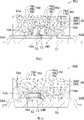
[0154]图10,示意地表示为本发明的第六实施例所涉及的半导体发光装置的白光LED装置的剖面结构。在此,用相同的符号也表示与图1及图6所示的结构因素相同的结构因素,来省略这些结构因素的说明。[0154] FIG. 10 schematically shows a cross-sectional structure of a white LED device which is a semiconductor light emitting device according to a sixth embodiment of the present invention. Here, the same components as those shown in FIGS. 1 and 6 are denoted by the same symbols, and descriptions of these components are omitted.
[0155]如图10所示,与第三实施例一样,在第六实施例所涉及的半导体发光装置30A中,LED芯片12以让LED芯片12的背面与衬底31的主面相向的、所谓的接合点在上侧(junction-up)的方式(朝上安装)安装在印刷布线衬底上,该印刷布线衬底包括衬底31,还至少包括选择性地形成在该衬底31的主面及背面的第一布线32A和第二布线32B。[0155] As shown in FIG. 10, as in the third embodiment, in the semiconductor light emitting device 30A according to the sixth embodiment, the
[0156]密封部26由第一密封部26A和第二密封部26B构成,该第一密封部26A以半球状直接覆盖半导体发光装置芯片12;该第二密封部26B以半球状直接覆盖该第一密封部26A。The sealing
[0157]第一密封部26A,由包含基体材料16a及第一微粒16b的复合材料所构成的密封材料16d、和荧光材料16c构成,所述第一微粒16b由无机材料构成,已均匀地分散在该基体材料16a的内部。[0157] The
[0158]第二密封部26B,由包含基体材料16a及第二微粒17b的复合材料所构成的密封材料16d、和荧光材料16c构成,所述第二微粒17b由无机材料构成,已均匀地分散在该基体材料16a的内部。在此,用与构成第一实施例的密封部16的材料一样的材料作为构成第一密封部26A及第二密封部26B的材料就可以。不过,在第六实施例中,选出折射率高于第二微粒17b的折射率的材料作为第一微粒16b。[0158] The
[0159]在包括晶体生长用衬底(外延衬底(epitaxial substrate))在内,LED芯片12由氮化镓(GaN)半导体构成的情况下,因为氮化镓的折射率如[图表1]所示约为2.5,所以即使通过添加微粒来将密封部的折射率设定为提取效率最高的1.8左右,该密封部的折射率与空气的折射率之差仍然也很大。[0159] In the case where the
[0160]因此,在第六实施例中,使离LED芯片12较近的第一密封部26A的折射率值高于离LED芯片12较远的第二密封部26B的折射率值。具体而言,采用折射率比添加在第一密封部26A中的第一微粒16b的折射率低的无机材料作为添加在第二密封部26B中的第二微粒17b。[0160] Therefore, in the sixth embodiment, the refractive index value of the
[0161]根据所述结构,因为与空气接触的第二密封部26B的折射率低于与LED芯片12接触的第一密封部26A的折射率,所以第二密封部26B的折射率与空气的折射率之间的差较小。因此,能够减低在第二密封部26B与空气之间的界面上会造成的、出射光的全反射,因而能够提高密封部26的耐光性和耐热性,能够进一步提高光提取效率。[0161] According to the structure, since the refractive index of the
[0162]此外,在第六实施例中,因为例如利用灌封成型(potting)法将第一密封部26A及第二密封部26B都形成为外形呈半球状,所以出射光的全反射进一步减低。[0162] In addition, in the sixth embodiment, since the
[0163]补充说明一下,在此对第一密封部26A和第二密封部26B都添加了荧光材料16c。也可以仅对第一密封部26A及第二密封部26B中的一个密封部添加荧光材料16c。[0163] As a supplementary note, here, the
[0164](第六实施例的第一变形例)(First modified example of the sixth embodiment)
图11,示意地表示为本发明的第六实施例的第一变形例所涉及的半导体发光装置的白光LED装置的剖面结构。FIG. 11 schematically shows a cross-sectional structure of a white LED device which is a semiconductor light emitting device according to a first modification of the sixth embodiment of the present invention.
[0165]如图11所示,在第一变形例所涉及的半导体发光装置30B中,将直接覆盖LED芯片12的第一密封部26A的剖面外形设为四角形。[0165] As shown in FIG. 11 , in the semiconductor light emitting device 30B according to the first modified example, the cross-sectional outer shape of the
[0166]这样,就能够利用印刷法作为用来形成第一密封部26A的密封材料16d的方法。因此,生产率提高。[0166] In this way, the printing method can be utilized as a method for forming the sealing
[0167](第六实施例的第二变形例)(Second modification of the sixth embodiment)
图12,示意地表示为本发明的第六实施例的第二变形例所涉及的半导体发光装置的白光LED装置的剖面结构。FIG. 12 schematically shows a cross-sectional structure of a white LED device which is a semiconductor light emitting device according to a second modified example of the sixth embodiment of the present invention.
[0168]如图12所示,在第二变形例所涉及的半导体发光装置30C中,将直接覆盖LED芯片12的第一密封部26A、和覆盖该第一密封部26A的第二密封部26B的剖面外形都设为四角形。[0168] As shown in FIG. 12, in the semiconductor light emitting device 30C according to the second modified example, the
[0169]这样,就能够利用印刷法作为用来形成第一密封部26A的密封材料16d的方法,也能够利用传递模塑法形成第二密封部26B。因此,生产率提高。而且,因为密封部26的上表面很平坦,所以能够容易地使用该半导体发光装置作为器件。[0169] In this way, the printing method can be used as the method for forming the sealing
[0170](第六实施例的第三变形例)(Third modification of the sixth embodiment)
图13,示意地表示为本发明的第六实施例的第三变形例所涉及的半导体发光装置的白光LED装置的剖面结构。FIG. 13 schematically shows a cross-sectional structure of a white LED device which is a semiconductor light emitting device according to a third modified example of the sixth embodiment of the present invention.
[0171]如图13所示,在第三变形例所涉及的半导体发光装置30D中,将直接覆盖LED芯片12的第一密封部26A的外形设为半球状,并将覆盖该第一密封部26A的第二密封部26B的剖面外形设为四角形。[0171] As shown in FIG. 13, in the semiconductor light emitting device 30D related to the third modified example, the outer shape of the
[0172]这样,全反射就由于外形呈半球状的第一密封部26A的影响而减低,并且由于上表面很平坦的第二密封部26B的影响而能够容易地使用该半导体发光装置作为器件。[0172] Thus, total reflection is reduced by the influence of the hemispherical
[0173](第六实施例的第四变形例)(Fourth modification of the sixth embodiment)
图14,示意地表示为本发明的第六实施例的第四变形例所涉及的半导体发光装置的白光LED装置的剖面结构。FIG. 14 schematically shows a cross-sectional structure of a white LED device which is a semiconductor light emitting device according to a fourth modification of the sixth embodiment of the present invention.
[0174]如图14所示,与第五实施例一样,在第四变形例所涉及的半导体发光装置50A中,LED芯片12利用朝上安装法被固定在具有凹部51a的壳体部件51中的凹部51a底面上。[0174] As shown in FIG. 14, as in the fifth embodiment, in the semiconductor
[0175]在此,直接覆盖LED芯片12的第一密封部26A、和覆盖该第一密封部26A的第二密封部26B的剖面形状,都呈四角形。[0175] Here, the cross-sectional shapes of the
[0176]在本变形例中,在将白色耐热性树脂材料用作壳体部件51的情况,或对壳体部件51的内侧壁面上进行了例如利用铝(Al)等金属的沉积等的金属化的情况下,该壳体部件51的内侧壁面起到反射面的作用。而且,因为将壳体部件51的内侧壁面设为从下方向上方变宽的倒锥形,所以除了用第一微粒16b和第二微粒17b使密封部26具有折射率差这一结构以外,光提取效率还根据壳体部件51及该壳体部件51的形状提高。[0176] In this modified example, in the case where a white heat-resistant resin material is used as the
[0177]补充说明一下,在形成第一密封部26A时想利用印刷法而不能直接对壳体部件51的凹部51a底面上进行印刷的情况下,例如只要事先将LED芯片12安装在副(sub)安装部件上,再在利用印刷法形成第一密封部26A后将该副安装部件安装在壳体部件51底面上就可以。[0177] As a supplementary note, when forming the
[0178]图15(a)和图15(b),表示在第六实施例的第四变形例所涉及的半导体发光装置50A中,通过模拟试验求出第一密封部26A及第二密封部26B的各种折射率与光提取效率之间的关系的结果。在此,图15(a)表示将氮化镓用作构成LED芯片12的衬底材料的情况;图15(b)表示将蓝宝石用作衬底材料的情况。在此,第一密封部26A的厚度设为500μm;第二密封部26B的厚度设为200μm。Fig. 15(a) and Fig. 15(b) show that in the semiconductor light-emitting
[0179]由图15(a)和图15(b)可见,在将氮化镓用作LED芯片12的衬底的情况下,第一密封部26A的折射率越高,光提取效率越高。而在将蓝宝石用作LED芯片12的衬底的情况下,第一密封部26A的折射率变化所带来的影响很小。[0179] It can be seen from FIG. 15(a) and FIG. 15(b) that when gallium nitride is used as the substrate of the
[0180]无论衬底是氮化镓的还是蓝宝石的,都有下述倾向,即:第二密封部26B的折射率越低,光提取效率就越高,并且光提取效率相对第一密封部26A的折射率变化的变化率越小。[0180] Regardless of whether the substrate is gallium nitride or sapphire, there is a tendency that the lower the refractive index of the
[0181](第六实施例的第五变形例)(Fifth modification of the sixth embodiment)
图16,示意地表示为本发明的第六实施例的第五变形例所涉及的半导体发光装置的白光LED装置的剖面结构。Fig. 16 schematically shows a cross-sectional structure of a white LED device which is a semiconductor light emitting device according to a fifth modified example of the sixth embodiment of the present invention.
[0182]如图16所示,在第五变形例所涉及的半导体发光装置50B中,LED芯片12被固定在具有凹部51a的壳体部件51中的凹部51a底面上。[0182] As shown in FIG. 16, in the semiconductor
[0183]在此,将直接覆盖LED芯片12的第一密封部26A的外形设为半球状,并将覆盖该第一密封部26A的第二密封部26B的剖面外形设为四角形。[0183] Here, the outer shape of the
[0184]这样,就能够利用外形呈半球状的第一密封部26A减低反射,能够利用壳体部件51提高光提取效率。[0184] In this way, reflection can be reduced by the
[0185](第六实施例的第六变形例)(Sixth modified example of the sixth embodiment)
图17,示意地表示为本发明的第六实施例的第六变形例所涉及的半导体发光装置的白光LED装置的剖面结构。Fig. 17 schematically shows a cross-sectional structure of a white LED device which is a semiconductor light emitting device according to a sixth modified example of the sixth embodiment of the present invention.
[0186]如图17所示,在第六变形例所涉及的半导体发光装置50C中,使添加在第二密封部26B的密封材料16d中的微粒16b的组成与添加在第一密封部26A的密封材料16d中的微粒16b的组成一样,并且使第一密封部26A中的微粒16b在密封材料16d中所占的比例高于第二密封部26B中的微粒16b在密封材料16d中所占的比例。就是说,使第二密封部26B中的微粒16b添加浓度低于第一密封部26A中的微粒16b添加浓度。在此,当设定添加浓度差时,也可以让浓度具有浓度梯度,也可以让浓度阶段性地变化。[0186] As shown in FIG. 17, in the semiconductor
[0187]通过所述做法也能使第二密封部26B的折射率小于第一密封部26A的折射率。[0187] By doing so, the refractive index of the
[0188]补充说明一下,在本变形例中,用同一组成的无机材料作为添加在第一密封部26A中的微粒16b及添加在第二密封部26B中的微粒16b,仅变更了添加浓度。只要使第二密封部26B的折射率小于第一密封部26A的折射率,就也可以采用下述做法来代替所述方法,该做法是:使添加在第一密封部26A中的微粒16b和添加在第二密封部26B中的微粒16b的组成及浓度不同。[0188] As a supplementary note, in this modified example, inorganic materials of the same composition are used as the
[0189]在图17中表示的是将直接覆盖LED芯片12的第一密封部26A的外形设为半球状的情况。也可以是这样的,与在第六实施例的第四变形例中说明的图14一样,将第一密封部26A的剖面外形设为四角形。[0189] FIG. 17 shows a case where the outer shape of the
[0190]与本变形例一样,也可以是这样的,在第六实施例和第六实施例的第一到第三变形例中,采用微粒16d来代替添加在第二密封部26B的密封材料16d中的微粒17b,使所述添加的微粒16d的组成与添加在第一密封部26A的密封材料16d中的微粒16b的组成一样,并使第一密封部26A中的微粒16b在密封材料16d中所占的比例高于第二密封部26B中的微粒16b在密封材料16d中所占的比例。[0190] Like this modified example, it may also be such that in the sixth embodiment and the first to third modified examples of the sixth embodiment,
[0191](第六实施例的第七变形例)(Seventh modified example of the sixth embodiment)
在第六实施例和各个变形例中,对第一密封部26A及第二密封部26B都添加了荧光材料16c。也可以仅对所述第一密封部26A及第二密封部26B中的一个密封部添加荧光材料16c。In the sixth embodiment and each modification, the
[0192]在图18所示的第七变形例所涉及的半导体发光装置50D中,例如采用能够发绿光的磷化镓(GaP)半导体作为LED芯片12。在该情况下,不需要对密封部26添加荧光材料16c。[0192] In a semiconductor
[0193]在用磷化镓半导体作为LED芯片12的情况下,以相向的方式将第一电极14A及第二电极14B分别形成在LED芯片12的下表面上和上表面上。第一电极14A,通过糊状银材料等具有导电性的芯片固定用糊状材料13与第一引线52A电连接;第二电极14B通过金属线15B与第二引线52B电连接。[0193] In the case of using a gallium phosphide semiconductor as the
[0194]补充说明一下,在第六实施例及其变形例中,将密封部26设为第一密封部26A及第二密封部26B所构成的双层结构,不过结构并不被限定于双层结构,也可以将结构设为三层以上的叠层结构。不过,若要设为三层以上的叠层结构,就需要设为:在各个密封部中,离LED芯片12越远的密封部的折射率越低。[0194] It should be added that in the sixth embodiment and its modified examples, the sealing
[0195](第七实施例)(seventh embodiment)
以下,参照附图,对本发明的第七实施例所涉及的半导体发光装置进行说明。Hereinafter, a semiconductor light emitting device according to a seventh embodiment of the present invention will be described with reference to the drawings.
[0196]图19,示意地表示为本发明的第七实施例所涉及的半导体发光装置的白光LED装置的剖面结构。在此,用相同的符号也表示与图1及图7所示的结构因素相同的结构因素,来省略这些结构因素的说明。[0196] FIG. 19 schematically shows a cross-sectional structure of a white LED device which is a semiconductor light emitting device according to a seventh embodiment of the present invention. Here, the same constituent elements as those shown in FIGS. 1 and 7 are denoted by the same symbols, and descriptions of these constituent elements are omitted.
[0197]如图19所示,与第四实施例一样,在第七实施例所涉及的半导体发光装置40A中,LED芯片12利用使LED芯片12的上表面与衬底31的主面相向的倒装芯片安装法安装在印刷布线衬底上,该印刷布线衬底包括衬底31,还至少包括选择性地形成在该衬底31的主面及背面的第一布线32A和第二布线32B。[0197] As shown in FIG. 19, like the fourth embodiment, in the semiconductor
[0198]密封部26,由第一密封部26A和第二密封部26B构成,该第一密封部26A以半球状直接覆盖半导体发光装置芯片12;该第二密封部26B以半球状直接覆盖该第一密封部26A。The sealing
[0199]第一密封部26A,由包含基体材料16a及第一微粒16b的复合材料所构成的密封材料16d、和荧光材料16c构成,所述第一微粒16b由无机材料构成,已均匀地分散在该基体材料16a的内部。[0199] The
[0200]第二密封部26B,由包含基体材料16a及第二微粒17b的复合材料所构成的密封材料16d、和荧光材料16c构成,所述第二微粒17b由无机材料构成,已均匀地分散在该基体材料16a的内部。在此,只要用与构成第一实施例的密封部16的材料一样的材料作为构成第一密封部26A及第二密封部26B的材料就可以。不过,需要选出折射率大于第二微粒17b的折射率的材料作为第一微粒16b。[0200] The
[0201]这样,就与第六实施例一样,在第七实施例中,位于离LED芯片12较近的内侧的第一密封部26A的折射率值也大于位于离LED芯片12较远的外侧的第二密封部26B的折射率值。[0201] In this way, just like the sixth embodiment, in the seventh embodiment, the refractive index value of the
[0202]就是说,因为根据所述结构,与空气接触的第二密封部26B的折射率小于与LED芯片12接触的第一密封部26A的折射率,所以第二密封部26B的折射率与空气的折射率之间的差较小。因此,能够减低出射光在第二密封部26B与空气之间的界面上会造成的全反射,因而能够提高密封部26的耐光性和耐热性,能够进一步提高光提取效率。That is, because according to the structure, the refractive index of the
[0203]此外,在本实施例中,因为例如利用灌封成型法将第一密封部26A及第二密封部26B都形成为外形呈半球状,所以出射光的全反射进一步减低。[0203] In addition, in this embodiment, since the
[0204]补充说明一下,在第七实施例中,对第一密封部26A和第二密封部26B都添加了荧光材料16c。也可以仅对第一密封部26A及第二密封部26B中的一个密封部添加荧光材料16c。[0204] As an additional note, in the seventh embodiment, the
[0205](第七实施例的第一变形例)(First modified example of the seventh embodiment)
图20,示意地表示为本发明的第七实施例的第一变形例所涉及的半导体发光装置的白光LED装置的剖面结构。FIG. 20 schematically shows a cross-sectional structure of a white LED device which is a semiconductor light emitting device according to a first modified example of the seventh embodiment of the present invention.
[0206]如图20所示,在第一变形例所涉及的半导体发光装置40B中,直接覆盖LED芯片12的第一密封部26A的剖面外形呈四角形。[0206] As shown in FIG. 20 , in the semiconductor
[0207]这样,就能够利用印刷法作为用来形成第一密封部26A的密封材料16d的方法。因此,生产率提高。[0207] In this way, the printing method can be utilized as a method for forming the sealing
[0208](第七实施例的第二变形例)(Second modification of the seventh embodiment)
图21,示意地表示为本发明的第七实施例的第二变形例所涉及的半导体发光装置的白光LED装置的剖面结构。FIG. 21 schematically shows a cross-sectional structure of a white LED device which is a semiconductor light emitting device according to a second modified example of the seventh embodiment of the present invention.
[0209]如图21所示,在第二变形例所涉及的半导体发光装置40C中,将直接覆盖LED芯片12的第一密封部26A、和覆盖该第一密封部26A的第二密封部26B的剖面外形都设为四角形。[0209] As shown in FIG. 21, in the semiconductor
[0210]这样,就能够利用印刷法作为用来形成第一密封部26A的密封材料16d的方法,也能够利用传递模塑法形成第二密封部26B。因此,生产率提高。而且,因为密封部26的上表面很平坦,所以能够容易地使用该半导体发光装置作为器件。[0210] In this way, the printing method can be used as a method for forming the sealing
[0211](第七实施例的第三变形例)(Third modification of the seventh embodiment)
图22,示意地表示为本发明的第七实施例的第三变形例所涉及的半导体发光装置的白光LED装置的剖面结构。FIG. 22 schematically shows a cross-sectional structure of a white LED device which is a semiconductor light emitting device according to a third modified example of the seventh embodiment of the present invention.
[0212]如图22所示,在第三变形例所涉及的半导体发光装置40D中,将直接覆盖LED芯片12的第一密封部26A的外形设为半球状,并将覆盖该第一密封部26A的第二密封部26B的剖面外形设为四角形。[0212] As shown in FIG. 22, in the semiconductor
[0213]这样,全反射就由于外形呈半球状的第一密封部26A的影响而减低,并且由于上表面很平坦的第二密封部26B的影响而能够容易地使用该半导体发光装置作为器件。[0213] Thus, the total reflection is reduced by the influence of the hemispherical
[0214](第七实施例的第四变形例)(Fourth modified example of the seventh embodiment)
图23,示意地表示为本发明的第七实施例的第四变形例所涉及的半导体发光装置的白光LED装置的剖面结构。FIG. 23 schematically shows a cross-sectional structure of a white LED device which is a semiconductor light emitting device according to a fourth modified example of the seventh embodiment of the present invention.
[0215]如图23所示,在第四变形例所涉及的半导体发光装置60中,LED芯片12利用倒装芯片安装法安装在具有凹部51a的壳体部件51中的凹部51a底面上。[0215] As shown in FIG. 23, in the semiconductor
[0216]在此,直接覆盖LED芯片12的第一密封部26A、和覆盖该第一密封部26A的第二密封部26B的剖面形状都是四角形。[0216] Here, the cross-sectional shapes of the
[0217]在本变形例中,若将白色耐热性树脂材料用作壳体部件51,该壳体部件51的内侧壁面就起到反射面的作用。而且,因为将壳体部件51的内侧壁面设为从下方向上方变宽的倒锥形,所以除了利用第一微粒16b及第二微粒17b使密封部26具有折射率差的结构以外,光提取效率还根据壳体部件51及该壳体部件51的形状提高。[0217] In this modified example, if a white heat-resistant resin material is used as the
[0218](第七实施例的第五变形例)(Fifth modification of the seventh embodiment)
图24,示意地表示为本发明的第七实施例的第五变形例所涉及的半导体发光装置的白光LED装置的剖面结构。Fig. 24 schematically shows a cross-sectional structure of a white LED device which is a semiconductor light emitting device according to a fifth modified example of the seventh embodiment of the present invention.
[0219]如图24所示,在第五变形例所涉及的半导体发光装置60A中,LED芯片12利用倒装芯片安装法隔着副安装部件53安装在具有凹部51a的壳体部件51中的凹部51a底面上。[0219] As shown in FIG. 24, in the semiconductor light-emitting
[0220]LED芯片12,利用倒装芯片安装法安装在上表面至少形成有第一副安装电极54A及第二副安装电极54B的、例如由陶瓷构成的副安装部件53上。[0220] The
[0221]具体而言,第一密封部26A,是利用印刷法以覆盖LED芯片12的方式形成的。具有被第一密封部26A密封着的LED芯片12的副安装部件53安装在壳体部件51的底面上。在形成于副安装部件53上表面上的第一副安装电极54A和第二副安装电极54B中,第一副安装电极54A通过第一金属线15A与第一引线52A电连接,第二副安装电极54B通过第二金属线15B与第二引线52B电连接。[0221] Specifically, the
[0222]补充说明一下,也可以将齐纳(Zener)二极管用作副安装部件53。[0222] Incidentally, a Zener diode may also be used as the
[0223]在图24中表示的是,将第一密封部26A的剖面外形设为四角形的情况。也可以将第一密封部26A的外形设为半球状。[0223] FIG. 24 shows a case where the cross-sectional outer shape of the
[0224](第七实施例的第六变形例)(Sixth modified example of the seventh embodiment)
图25,示意地表示为本发明的第七实施例的第六变形例所涉及的半导体发光装置的白光LED装置的剖面结构。Fig. 25 schematically shows a cross-sectional structure of a white LED device which is a semiconductor light emitting device according to a sixth modified example of the seventh embodiment of the present invention.
[0225]如图25所示,在第六变形例所涉及的半导体发光装置60B中,LED芯片12利用倒装芯片安装法安装并固定在具有凹部51a的壳体部件51中的凹部51a底面上。[0225] As shown in FIG. 25, in the semiconductor
[0226]在此,将直接覆盖LED芯片12的第一密封部26A的外形设为半球状,将覆盖该第一密封部26A的第二密封部26B的剖面外形设为四角形。[0226] Here, the outer shape of the
[0227]这样,外形呈半球状的第一密封部26A就减低全反射,壳体部件51使光提取效率提高。[0227] In this way, the
[0228](第七实施例的第七变形例)(Seventh modified example of the seventh embodiment)
图26,示意地表示为本发明的第七实施例的第七变形例所涉及的半导体发光装置的白光LED装置的剖面结构。FIG. 26 schematically shows a cross-sectional structure of a white LED device which is a semiconductor light emitting device according to a seventh modification of the seventh embodiment of the present invention.
[0229]如图26所示,在第七变形例所涉及的半导体发光装置60C中,使添加在第二密封部26B的密封材料16d中的微粒16b的组成与添加在第一密封部26A的密封材料16d中的微粒16b的组成一样,并使第一密封部26A中的微粒16b在密封材料16d中所占的比例高于第二密封部26B中的微粒16b在密封材料16d中所占的比例。就是说,使第二密封部26B中的微粒16b添加浓度低于第一密封部26A中的微粒16b添加浓度。在此,当设定添加浓度差时,也可以让浓度具有浓度梯度,也可以让浓度阶段性地变化。[0229] As shown in FIG. 26, in the semiconductor
[0230]通过所述做法也能使第二密封部26B的折射率小于第一密封部26A的折射率。[0230] Also by doing so, the refractive index of the
[0231]补充说明一下,在本变形例中,用同一组成的无机材料作为添加在第一密封部26A中的微粒16b及添加在第二密封部26B中的微粒16b,仅变更了该无机材料的添加浓度。只要使第二密封部26B的折射率小于第一密封部26A的折射率,就也可以采用下述做法来代替所述方法,该做法是:使添加在第一密封部26A中的微粒16b和添加在第二密封部26B中的微粒16b的组成及浓度不同。[0231] As a supplementary explanation, in this modified example, inorganic materials of the same composition are used as the
[0232]在图26中表示的是将直接覆盖LED芯片12的第一密封部26A的外形设为半球状的情况。也可以是这样的,与在第七实施例的第四变形例中说明的图23一样,将第一密封部26A的剖面外形设为四角形。[0232] FIG. 26 shows a case where the outer shape of the
[0233]与本变形例一样,也可以是这样的,在第七实施例和第七实施例的第一到第三及第五变形例中,采用微粒16d来代替添加在第二密封部26B的密封材料16d中的微粒17b,使所述添加的微粒16d的组成与添加在第一密封部26A的密封材料16d中的微粒16b的组成一样,并使第一密封部26A中的微粒16b在密封材料16d中所占的比例高于第二密封部26B中的微粒16b在密封材料16d中所占的比例。[0233] Like this modified example, it may also be such that in the seventh embodiment and the first to third and fifth modified examples of the seventh embodiment,
[0234]在第七实施例及各个变形例中,对第一密封部26A及第二密封部26B都添加了荧光材料16c。也可以仅对第一密封部26A及第二密封部26B中的一个密封部添加荧光材料16c。[0234] In the seventh embodiment and each modification, the
[0235]补充说明一下,在第七实施例及其变形例中,将密封部26设为第一密封部26A及第二密封部26B所构成的双层结构,不过结构并不被限定于双层结构,也可以将结构设为三层以上的叠层结构。不过,若要设为三层以上的叠层结构,就需要设为:在各个密封部中,离LED芯片12越远的密封部的折射率越低。[0235] It should be added that in the seventh embodiment and its modifications, the sealing
[0236](第八实施例)(eighth embodiment)
下面,参照附图,对本发明的第八实施例所涉及的半导体发光装置进行说明。Next, a semiconductor light emitting device according to an eighth embodiment of the present invention will be described with reference to the drawings.
[0237]图27,示意地表示为本发明的第八实施例所涉及的半导体发光装置的白光LED装置的剖面结构。在此,用相同的符号也表示与图1及图6所示的结构因素相同的结构因素,来省略这些结构因素的说明。[0237] FIG. 27 schematically shows a cross-sectional structure of a white LED device which is a semiconductor light emitting device according to an eighth embodiment of the present invention. Here, the same components as those shown in FIGS. 1 and 6 are denoted by the same symbols, and descriptions of these components are omitted.
[0238]如图27所示,与第三实施例一样,在第八实施例所涉及的半导体发光装置30E中,LED芯片12以让LED芯片12的背面与衬底31的主面相向的、所谓的接合点在上侧(junction-up)的方式(朝上安装)安装在印刷布线衬底上,该印刷布线衬底包括衬底,还至少包括选择性地形成在该衬底31的主面及背面的第一布线32A和第二布线32B。[0238] As shown in FIG. 27, as in the third embodiment, in the semiconductor
[0239]密封部16由包含基体材料16a及微粒16b的复合材料所构成的密封材料16d、和荧光材料16c构成,所述微粒16b由无机材料构成,已均匀地分散在该基体材料16a的内部。用与构成第一实施例的密封部16的材料一样的材料作为构成密封部16的材料就可以。不过,在第八实施例中,设为:使离LED芯片12较近的内侧区域的、微粒16b在复合材料中所占的比例高于处在该内侧区域的外侧的外侧区域的、微粒16b在复合材料中所占的比例。The sealing
[0240]在包括晶体生长用衬底(外延衬底(epitaxial substrate))在内,LED芯片12由氮化镓(GaN)半导体构成的情况下,因为氮化镓的折射率如[图表1]所示约为2.5,所以即使通过添加微粒来将密封部的折射率设定为提取效率最高的1.8左右,该密封部的折射率与空气的折射率之差仍然也很大。[0240] In the case where the
[0241]于是,在第八实施例中,使密封部16中的离LED芯片12较近的内侧区域的折射率值高于处在该内侧区域的外侧的外侧区域的折射率值。具体而言,在内侧区域将添加在密封部16中的微粒16b的浓度设为较高的值,使微粒16b的浓度向外侧逐渐变低,从而使密封部16的外侧区域的折射率低于处在该外侧区域的内侧的内侧区域的折射率。这时,也可以使微粒16b的浓度从内侧向外侧逐渐变低,也可以使微粒16b的浓度从内侧向外侧阶段性地变低。[0241] Therefore, in the eighth embodiment, the refractive index value of the inner region closer to the
[0242]因此,根据所述结构,与空气接触的密封部16的外侧区域的折射率低于与LED芯片12接触的内侧区域的折射率,因而密封部16的外侧区域的折射率和空气的折射率之差较小。因此,能够减低出射光在密封部16与空气之间的界面造成的全反射,因而密封部16的耐光性及耐热性提高,并且能够进一步提高光提取效率。[0242] Therefore, according to the structure, the refractive index of the outer region of the sealing
[0243]此外,在第本实施例中,因为例如利用灌封成型(potting)法将密封部16形成为外形呈半球状,所以出射光的全反射进一步减低。在此,作为使微粒16b的添加浓度在内侧区域较高而在外侧区域较低的方法,可以举出用硬化前的液状复合材料进行多次灌封成型的方法。就是说,只要以让外侧区域用复合材料中的微粒16b的添加比例小于内侧区域用复合材料的添加比例的方式进行灌封成型就可以。这时,也可以是这样的,选出折射率低于第一次灌封成型的微粒16b的折射率的、由无机材料构成的其他微粒作为第二次以后的灌封成型的微粒16b。之后,能够通过硬化使所述液状复合材料成为由复合材料构成的密封部16,来形成本实施例的结构。[0243] Furthermore, in the present embodiment, since the sealing
[0244]补充说明一下,在第八实施例中,对密封部16添加了荧光材料16c。不过,如上所述,在采用磷化镓(GaP)半导体作为LED芯片12而构成的绿光LED装置等的情况下,不需要使密封部16包含荧光材料16c。[0244] As a supplementary note, in the eighth embodiment, the
[0245](第八实施例的第一变形例)(First modified example of the eighth embodiment)
图28,示意地表示为本发明的第八实施例的第一变形例所涉及的半导体发光装置的白光LED装置的剖面结构。Fig. 28 schematically shows a cross-sectional structure of a white LED device which is a semiconductor light emitting device according to a first modification of the eighth embodiment of the present invention.
[0246]如图28所示,在第一变形例所涉及的半导体发光装置30F中,将微粒16b的添加浓度向外侧逐渐减低的密封部16的剖面外形设为四角形。[0246] As shown in FIG. 28 , in the semiconductor
[0247]作为本变形例所涉及的密封部16中的密封材料16d的形成方法,可以利用以使密封部16的外侧的微粒16b添加浓度低于密封部16的内侧的微粒16b添加浓度的方式多次进行传递模塑的方法。[0247] As a method for forming the sealing
[0248](第八实施例的第二变形例)(Second modification of the eighth embodiment)
图29,示意地表示为本发明的第八实施例的第二变形例所涉及的半导体发光装置的白光LED装置的剖面结构。Fig. 29 schematically shows a cross-sectional structure of a white LED device which is a semiconductor light emitting device according to a second modified example of the eighth embodiment of the present invention.
[0249]如图29所示,与第五实施例一样,在第二变形例所涉及的半导体发光装置50E中,LED芯片12利用朝上安装法被固定在具有凹部51a的壳体部件51中的凹部51a底面上。[0249] As shown in FIG. 29, as in the fifth embodiment, in the semiconductor
[0250]在此,覆盖LED芯片12的密封部16A的剖面形状是四角形。[0250] Here, the cross-sectional shape of the sealing portion 16A covering the
[0251]在本变形例中,在将白色耐热性树脂材料用作壳体部件51的情况,或对壳体部件51的内侧壁面上进行了例如利用铝(Al)等金属的沉积等的金属化的情况下,该壳体部件51的内侧壁面起到反射面的作用。而且,因为将壳体部件51的内侧壁面设为从下方向上方变宽的倒锥形,所以除了使微粒16b的添加浓度向外侧逐渐变低来使密封部16具有逐渐变低的折射率差这一结构以外,光提取效率还根据壳体部件51及该壳体部件51的形状提高。[0251] In this modified example, in the case where a white heat-resistant resin material is used as the
[0252]补充说明一下,能够通过进行多次灌封成型来形成本变形例所涉及的密封部16。[0252] As a supplementary note, the sealing
[0253](第九实施例)(ninth embodiment)
下面,参照附图,对本发明的第九实施例所涉及的半导体发光装置进行说明。Next, a semiconductor light emitting device according to a ninth embodiment of the present invention will be described with reference to the drawings.
[0254]图30,示意地表示为本发明的第九实施例所涉及的半导体发光装置的白光LED装置的剖面结构。在此,用相同的符号也表示与图1及图7所示的结构因素相同的结构因素,来省略这些结构因素的说明。[0254] FIG. 30 schematically shows a cross-sectional structure of a white LED device which is a semiconductor light emitting device according to a ninth embodiment of the present invention. Here, the same constituent elements as those shown in FIGS. 1 and 7 are denoted by the same symbols, and descriptions of these constituent elements are omitted.
[0255]如图30所示,与第四实施例一样,在第九实施例所涉及的半导体发光装置40E中,LED芯片12利用使LED芯片12的上表面与衬底31的主面相向的倒装芯片安装法安装在印刷布线衬底上,该印刷布线衬底包括衬底31,还至少包括选择性地形成在该衬底31的主面及背面的第一布线32A和第二布线32B。[0255] As shown in FIG. 30, as in the fourth embodiment, in the semiconductor light emitting device 40E according to the ninth embodiment, the
[0256]密封部16由包含基体材料16a及微粒16b的复合材料所构成的密封材料16d、和荧光材料16c构成,所述微粒16b由无机材料构成,已均匀地分散在该基体材料16a的内部。用与构成第一实施例的密封部16的材料一样的材料作为构成密封部16的材料就可以。不过,在第九实施例中,设为:使离LED芯片12较近的内侧区域的、微粒16b在复合材料中所占的比例高于处在该内侧区域的外侧的外侧区域的、微粒16b在复合材料中所占的比例。[0256] The sealing
[0257]这样,在第六实施例和第八实施例一样,在第九实施例中,离LED芯片12较近的、密封部16内侧区域的折射率值也高于处在该内侧区域外侧的外侧区域的折射率值。[0257] Thus, in the sixth embodiment and the eighth embodiment, in the ninth embodiment, the refractive index value of the inner region of the sealing
[0258]就是说,根据所述结构,因为与空气接触的、密封部16的外侧区域的折射率低于与LED芯片12接触的内侧区域的折射率,因而密封部16的外侧区域的折射率和空气的折射率之差较小。因此,能够减低出射光在密封部16与空气之间的界面造成的全反射,因而密封部16的耐光性及耐热性提高,并且能够进一步提高光提取效率。在此,也可以让微粒16b的添加浓度从内侧向外侧逐渐变低;也可以让该添加浓度阶段性地变低。[0258] That is, according to the structure, since the refractive index of the outer region of the sealing
[0259]此外,在第本实施例中,因为例如利用灌封成型法将密封部16形成为外形呈半球状,所以出射光的全反射进一步减低。在此,作为使微粒16b的添加浓度在内侧区域较高而在外侧区域较低的方法,可以举出用硬化前的液状复合材料进行多次灌封成型的方法。就是说,只要以让外侧区域用复合材料中的微粒16b添加比例低于内侧区域用复合材料的添加比例的方式进行灌封成型就可以。这时,也可以是这样的,选出折射率低于第一次灌封成型的微粒16b的折射率的、由无机材料构成的其他微粒作为第二次以后的灌封成型的微粒16b。之后,能够通过硬化使所述液状复合材料成为由复合材料构成的密封部16,来形成本实施例的结构。[0259] Furthermore, in the present embodiment, since the sealing
[0260]此外,因为在第九实施例中,利用灌封成型法将密封部16形成为外形呈半球状,所以出射光的全反射进一步减低。[0260] Furthermore, since in the ninth embodiment, the sealing
[0261]补充说明一下,在此使密封部16包含荧光材料16c。不过,如上所述,在采用磷化镓(GaP)半导体作为LED芯片12而构成的绿光LED装置等的情况下,不需要使密封部16包含荧光材料16c。[0261] As a supplementary note, here, the sealing
[0262](第九实施例的第一变形例)(First Modification of Ninth Embodiment)
图31,示意地表示为本发明的第九实施例的第一变形例所涉及的半导体发光装置的白光LED装置的剖面结构。FIG. 31 schematically shows a cross-sectional structure of a white LED device which is a semiconductor light emitting device according to a first modification of the ninth embodiment of the present invention.
[0263]如图31所示,在第一变形例所涉及的半导体发光装置40F中,将微粒16b的添加浓度向外侧逐渐变低的密封部16的剖面外形设为四角形。[0263] As shown in FIG. 31 , in the semiconductor light emitting device 40F according to the first modification, the cross-sectional outer shape of the sealing
[0264]作为形成本变形例所涉及的密封部16中的密封材料16d的方法,可以利用以使密封部16的外侧的微粒16b添加浓度低于密封部16的内侧的微粒16b添加浓度的方式多次进行传递模塑的方法。[0264] As a method of forming the sealing
[0265](第九实施例的第二变形例)(Second Modification of Ninth Embodiment)
图32,示意地表示为本发明的第九实施例的第二变形例所涉及的半导体发光装置的白光LED装置的剖面结构。Fig. 32 schematically shows a cross-sectional structure of a white LED device which is a semiconductor light emitting device according to a second modified example of the ninth embodiment of the present invention.
[0266]如图32所示,在第二变形例所涉及的半导体发光装置60E中,LED芯片12利用倒装芯片安装法安装在具有凹部51a的壳体部件51中的凹部51a底面上。[0266] As shown in FIG. 32, in the semiconductor
[0267]在此,覆盖LED芯片12的密封部16A的剖面形状为四角形。[0267] Here, the cross-sectional shape of the sealing portion 16A covering the
[0268]在本变形例中,在将白色耐热性树脂材料用作壳体部件51的情况,或对壳体部件51的内侧壁面进行了例如利用铝(Al)等金属的沉积等的金属化的情况下,该壳体部件51的内侧壁面起到反射面的作用。而且,因为将壳体部件51的内侧壁面设为从下方向上方变宽的倒锥形,所以除了使微粒16b的添加浓度向外侧逐渐变低来使密封部16具有逐渐变低的折射率差这一结构以外,光提取效率还根据壳体部件51及该壳体部件51的形状提高。[0268] In this modified example, in the case where a white heat-resistant resin material is used as the
[0269]补充说明一下,能够通过进行多次灌封成型来形成本变形例所涉及的密封部16。[0269] As a supplementary note, the sealing
[0270]在本变形例中,也可以采用下述结构,即:如在第七实施例的第五变形例中说明的那样,LED芯片12通过副安装部件53利用倒装芯片安装法安装在具有凹部51a的壳体部件51中的凹部51a底面上的结构。[0270] In this modified example, the following structure may also be adopted, that is, as explained in the fifth modified example of the seventh embodiment, the
[0271](第十实施例)(tenth embodiment)
图33,示意地表示为本发明的第十实施例所涉及的半导体发光装置的白光LED装置的剖面结构。在此,用相同的符号也表示与图6及图10所示的结构因素相同的结构因素,来省略这些结构因素的说明。Fig. 33 schematically shows a cross-sectional structure of a white LED device which is a semiconductor light emitting device according to a tenth embodiment of the present invention. Here, the same components as those shown in FIG. 6 and FIG. 10 are denoted by the same symbols, and descriptions of these components are omitted.
[0272]如图33所示,与第六实施例一样,在第十实施例所涉及的半导体发光装置30G中,LED芯片12以让LED芯片12的背面与衬底31的主面相向的、所谓的接合点在上侧(junction-up)的方式(朝上安装)安装在印刷布线衬底上,该印刷布线衬底包括衬底31,还至少包括选择性地形成在该衬底31的主面及背面的第一布线32A和第二布线32B。[0272] As shown in FIG. 33, as in the sixth embodiment, in the semiconductor
[0273]密封部26由第一密封部26A和第二密封部26B构成,该第一密封部26A以半球状直接覆盖半导体发光装置芯片12;该第二密封部26B以半球状直接覆盖该第一密封部26A。[0273] The sealing
[0274]第一密封部26A,由混合有荧光材料16c的树脂材料构成;第二密封部26B,由包含基体材料16a及微粒16b的复合材料所构成的密封材料16d构成,所述微粒16b由无机材料构成,已均匀地分散在该基体材料16a的内部。The
[0275]图34,表示采用直径在3nm到10nm的氧化锆(ZrO2)作为添加于第二密封部26B中的微粒16b并将该微粒16b相对基体材料16a的体积百分比设为30%的情况下的、光的波长与透光率之间的关系。由图34可见,透光率在波长短的一侧大幅度减小。在此,将该现象称为过滤效应。[0275] FIG. 34 shows a situation in which diameters of zirconia (ZrO2 ) from 3nm to 10nm are used as the
[0276]根据第十实施例所涉及的半导体发光装置30G,能够得到与第一实施例一样的效果,而且由于所述过滤效应,红光区的光谱成分如图35所示相对地增大。就是说,在LED芯片12所放射的放射光和荧光材料16c所激发出的合成光中,由于微粒16b的存在而发生的散射,蓝光区到紫外光区的光谱成分衰减,红光区的光谱成分相对地增大。在此,在测量时使用的半导体发光装置中,采用了图23所示的、将LED芯片12安装在壳体部件51中的结构。LED芯片12的放射光是峰值波长为460nm的蓝光,荧光材料16c的激发光是峰值波长为575nm的黄光。在此,荧光材料16c,是对峰值波长为590nm的橙光用荧光材料和峰值波长为535nm的绿光用荧光材料进行调配而成的。[0276] According to the semiconductor
[0277]这样,平均演色性指数Ra就升高,色温下降,如[图表2]所示。在此,平均演色性指数Ra很高,意味着被某个光源照的东西的彩色再现性很优良。色温很低,意味着光源呈暖色。[0277] Thus, the average color rendering index Ra increases, and the color temperature decreases, as shown in [Graph 2]. Here, the high average color rendering index Ra means that the color reproducibility of a thing illuminated by a certain light source is excellent. A very low color temperature means that the light source appears warm.
[0278][图表2][Graph 2]
[0279]在此,比较例表示未设置第二密封部26B的结构的情况;本发明1表示包含微粒16b的第二密封部26B的厚度为0.2mm的情况;本发明2表示第二密封部26B的厚度为1mm的情况。[0279] Here, the comparative example represents the situation in which the structure of the
[0280]由图表2可见,与比较例相比,本发明1的情况下的平均演色性指数更高;本发明2的情况下的色温比比较例低400K。在此,色温的duv(色度坐标上的从黑体曲线算起的差)值在±0.002。As can be seen from
[0281]补充说明一下,也可以设为下述结构作为第十实施例的第一变形例,即:将能够得到绿光或黄光的荧光材料分别添加在第一密封部26A和第二密封部26B中。通过该做法,由于添加在第二密封部26B中的微粒16b的影响,合成光中的蓝光区到紫外光区的光谱成分也大幅度衰减,红光区的光谱成分相对地增大。[0281] As a supplementary explanation, the following structure can also be set as the first modified example of the tenth embodiment, that is, fluorescent materials that can obtain green light or yellow light are respectively added to the
[0282]也可以设为下述结构作为第二变形例,即:将能够得到绿光或黄光的第一荧光材料添加在第一密封部26A中,将微粒16b和能够得到红光的第二荧光材料添加在第二密封部26B中。这样,红光用第二荧光材料就吸收来自第一荧光材料的绿光或黄光,红光被激发,因而红光区的光谱成分进一步增大。这样,平均演色性指数Ra就进一步升高,色温进一步下降。[0282] It is also possible to make the following structure as a second modified example, that is, the first fluorescent material that can obtain green light or yellow light is added in the
[0283]也可以设为下述结构作为第三变形例,即:将能够得到红光的第一荧光材料添加在第一密封部26A中,将微粒16b和能够得到绿光或黄光的第二荧光材料添加在第二密封部26B中。这样,红光用第一荧光材料就不吸收第二荧光材料的发光光即绿光或黄光。因此,LED芯片12所放射的放射光的变换效率就提高。Also can be made as following structure as the 3rd modified example, namely: the first fluorescent material that can obtain red light is added in the
[0284]最好是这样的,在第十实施例及各个变形例中,与第六实施例一样,使第一密封部26A的折射率小于LED芯片的折射率,使第二密封部26B的折射率小于第一密封部26A的折射率。这样,光提取效率就提高。[0284] Preferably, in the tenth embodiment and each modified example, as in the sixth embodiment, the refractive index of the
[0285]补充说明一下,在LED芯片12的放射光的波长不是在于蓝光区,而是在于410nm以下的蓝紫光区到380nm以下的紫外光区的情况下,通过除了绿光用及红光用、或黄光用的各种荧光材料以外还将蓝光用荧光材料至少添加在第一密封部26A中,能够得到白色合成光。[0285] It should be added that the wavelength of the radiated light of the
[0286]半导体发光装置30G的外形和安装LED芯片12的方法并不限于图33所示的样子,也可以设为与第二实施例、第六实施例的第一到第五变形例或者第七实施例的第一到第六变形例一样的结构。[0286] The shape of the semiconductor
[0287](第十实施例的第四变形例)(Fourth modified example of the tenth embodiment)
图36,示意地表示为本发明的第十实施例的第四变形例所涉及的半导体发光装置的白光LED装置的剖面结构。在此,用相同的符号也表示与图8及图14所示的结构因素相同的结构因素,来省略这些结构因素的说明。Fig. 36 schematically shows a cross-sectional structure of a white LED device which is a semiconductor light emitting device according to a fourth modified example of the tenth embodiment of the present invention. Here, the same constituent elements as those shown in FIG. 8 and FIG. 14 are denoted by the same symbols, and descriptions of these constituent elements are omitted.
[0288]如图36所示,与第五实施例一样,在第四变形例所涉及的半导体发光装置50F中,LED芯片12利用朝上安装法被固定在具有凹部51a的壳体部件51中的凹部51a底面上。[0288] As shown in FIG. 36, as in the fifth embodiment, in the semiconductor
[0289]第一密封部26A由混合有荧光材料16c的树脂材料构成。第二密封部26B,由包含基体材料16a及微粒16b的复合材料所构成的密封材料16d构成,所述微粒16b由无机材料构成,已均匀地分散在该基体材料16a的内部。[0289] The
[0290]在第四变形例中,第一密封部26A形成为与LED芯片12接触并覆盖该LED芯片12的周围;第二密封部26B以与壳体51的底面平行的方式设置在壳体51的上端面上。因此,在第二密封部26B与第一密封部26A之间形成有空隙部51b。[0290] In the fourth modified example, the
[0291]再加上,在空隙部51b中形成有覆盖第一密封部26A的第一透镜70,在第二密封部26B上形成有覆盖该第二密封部26B的第二透镜部71。在此,作为第一透镜70及第二透镜71,例如可以采用硅树脂、环氧树脂、烯烃树脂、丙烯树脂、尿素树脂、亚胺树脂、聚碳酸脂树脂或玻璃等等。补充说明一下,并不一定需要设置第二透镜71。[0291] In addition, the
[0292]如上所述,根据本变形例,半导体发光装置即使具有在第一密封部26A与第二密封部26B之间设有空隙部51b的结构,由于过滤效应,也能够得到第十实施例中的、平均演色性指数增大并且色温下降的效果。[0292] As described above, according to this modified example, even if the semiconductor light emitting device has a structure in which the
[0293]可以利用灌封成型法作为本变形例所涉及的各个透镜70、71的形成方法。第二密封部26B是能通过事先形成为板状,再将该板状物固定在壳体51的上端面上来形成的。[0293] A potting molding method can be used as a method of forming the
[0294](第十实施例的第五变形例)(Fifth modification of the tenth embodiment)
图37,示意地表示为本发明的第十实施例的第五变形例所涉及的半导体发光装置的白光LED装置的剖面结构。在此,用相同的符号也表示与图8及图14所示的结构因素相同的结构因素,来省略这些结构因素的说明。Fig. 37 schematically shows a cross-sectional structure of a white LED device which is a semiconductor light emitting device according to a fifth modified example of the tenth embodiment of the present invention. Here, the same constituent elements as those shown in FIG. 8 and FIG. 14 are denoted by the same symbols, and descriptions of these constituent elements are omitted.
[0295]如图37所示,与第五实施例一样,在第十实施例的第五变形例所涉及的半导体发光装置50G中,LED芯片12利用朝上安装法被固定在具有凹部51a的壳体部件51中的凹部51a底面上。[0295] As shown in FIG. 37, like the fifth embodiment, in the semiconductor
[0296]第一密封部26A由混合有荧光材料16c的树脂材料构成;第二密封部26B,由包含基体材料16a及微粒16b的复合材料所构成的密封材料16d构成,所述微粒16b由无机材料构成,已均匀地分散在该基体材料16a的内部。The
[0297]在第五变形例中,第一密封部26A形成为与LED芯片12接触并覆盖该LED芯片12的周围;第二密封部26B以保留壳体51的凹部51a的上部的方式填充在该壳体51的凹部51a中。在凹部51a的上部形成有空隙部51b。[0297] In the fifth modified example, the
[0298]再加上,在壳体51的上端面上以覆盖空隙部51b的方式形成有透镜70。[0298] In addition, a
[0299]补充说明一下,在第一密封部26A具有透镜功能的情况下,并不一定需要设置透镜70。[0299] As a supplementary note, when the
[0300]如上所述,根据本变形例,半导体发光装置即使具有在第二密封部26B与透镜70之间设有空隙部51b的结构,由于过滤效应,也能够得到第十实施例中的、平均演色性指数增大并且色温下降的效果。[0300] As described above, according to this modified example, even if the semiconductor light emitting device has a structure in which the
[0301]补充说明一下,本变形例所涉及的透镜70,是能通过事先用成型模等进行成型,再将该成型物固定在壳体51的上端面上来形成的。[0301] It should be added that the
[0302](第十实施例的第六变形例)(Sixth modified example of the tenth embodiment)
图38,示意地表示为本发明的第十实施例的第六变形例所涉及的半导体发光装置的白光LED装置的剖面结构。在此,用相同的符号也表示与图8及图37所示的结构因素相同的结构因素,来省略这些结构因素的说明。Fig. 38 schematically shows a cross-sectional structure of a white LED device which is a semiconductor light emitting device according to a sixth modification of the tenth embodiment of the present invention. Here, the same components as those shown in FIG. 8 and FIG. 37 are denoted by the same symbols, and descriptions of these components are omitted.
[0303]如图38所示,第十实施例的第六变形例所涉及的半导体发光装置80包括反射器81,该反射器81例如由液晶聚合物等耐热性树脂材料构成,在上端部分上至少固定有第一引线52A及第二引线52B,在内部具有呈凹状即呈半球面状或抛物面状的反射部81a,兼作壳体。补充说明一下,若考虑到对可见光进行的反射,就最好用白色耐热性树脂材料作为该反射器81,或者用铝等金属对反射部81a进行金属化。[0303] As shown in FIG. 38 , the semiconductor
[0304]LED芯片12,利用朝上安装法被固定在第一引线52A的下表面上。就是说,LED芯片12被安装,使得LED芯片12的上表面与反射部81a的底部相向。[0304] The
[0305]在反射部81a的反射面上形成有由混合有荧光材料16c的树脂材料构成的荧光体层27,在荧光体层27与LED芯片12之间形成有空隙部81b。在反射器81的上端面上,以覆盖包括各条引线52A、52B在内的空隙部81b的方式形成有密封部16。密封部16,由包含基体材料16a及微粒16b的复合材料所构成的密封材料16d构成,所述微粒16b由无机材料构成,已均匀地分散在该基体材料16a的内部。[0305] A
[0306]在密封部16上形成有透镜70。不过,并不一定需要设置透镜70。[0306] A
[0307]如上所述,半导体发光装置即使具有将LED芯片12设置在反射器81中的反射部81a的焦点附近的结构,也能够得到本发明的效果。[0307] As described above, even if the semiconductor light emitting device has a structure in which the
[0308]补充说明一下,也可以将密封用树脂材料填充于反射器81的空隙部81b中,进而也可以将组成与密封部16相同的复合材料或折射率不同的复合材料填充于反射器81的空隙部81b中。[0308] As a supplementary explanation, the sealing resin material may also be filled in the
[0309](第十一实施例)(Eleventh embodiment)
图39,示意地表示为本发明的第十一实施例所涉及的半导体发光装置的白光LED装置的剖面结构。在此,用相同的符号也表示与图8及图14所示的结构因素相同的结构因素,来省略这些结构因素的说明。Fig. 39 schematically shows a cross-sectional structure of a white LED device which is a semiconductor light emitting device according to an eleventh embodiment of the present invention. Here, the same constituent elements as those shown in FIG. 8 and FIG. 14 are denoted by the same symbols, and descriptions of these constituent elements are omitted.
[0310]如图39所示,与第五实施例一样,在第十一实施例所涉及的半导体发光装置50H中,LED芯片12利用朝上安装法被固定在具有凹部51a的壳体部件51中的凹部51a底面上。[0310] As shown in FIG. 39, like the fifth embodiment, in the semiconductor
[0311]用白色耐热性树脂材料作为壳体部件51,或者对壳体部件51的凹部51a的内侧壁面上及底面上进行例如利用铝(Al)等金属的沉积等的金属化,来使该壳体部件51的内表面起到反射面的作用。[0311] Use a white heat-resistant resin material as the
[0312]密封部26由第一密封部26A和第二密封部26B构成,该第一密封部26A直接覆盖LED芯片12,被填充于壳体部件51的凹部51a的下部;该第二密封部26B形成在该第一密封部26A上,呈层状。[0312] The sealing
[0313]第一密封部26A,由包含基体材料16a及微粒16b的复合材料所构成的密封材料16d构成,所述微粒16b由无机材料构成,已均匀地分散在该基体材料16a的内部;第二密封部26B由混合有荧光材料16c的树脂材料构成。The
[0314]根据所述结构,由添加在第二密封部26B中的荧光材料16c反射的、来自LED芯片12的放射光的一部分及来自荧光材料16c的发光光的一部分在壳体部件51中的凹部51a的内侧壁面或底面、与第一密封部26A之间的界面进行反射,再次透过第一密封部26A。[0314] According to the above structure, part of the radiated light from the
[0315]根据第十一实施例所涉及的半导体发光装置50H,能够得到与第一实施例一样的效果,而且由于所述蓝光区到紫外光区的合成光衰减的过滤效应,红光区的光谱成分相对地增大。这样,平均演色性指数就升高,色温下降。[0315] According to the semiconductor light-emitting
[0316]补充说明一下,也可以这样设定作为第十一实施例的第一变形例,即:在LED芯片12的放射光是蓝光的情况下,将能够得到绿光或黄光的荧光材料分别添加在第一密封部26A和第二密封部26B中。这样,就通过添加在第一密封部26A中的微粒16b使合成光中的蓝光区到紫外光区的光谱成分衰减,红光区的光谱成分还是相对地增大。[0316] As a supplementary note, it is also possible to set as the first modified example of the eleventh embodiment in this way, that is, when the radiated light of the
[0317]也可以这样设定作为第二变形例,即:将微粒16b和能够得到绿光或黄光的第一荧光材料添加在第一密封部26A中,将能够得到红光的第二荧光材料添加在第二密封部26B中。这样,红光用第二荧光材料就吸收来自第一荧光材料的绿光或黄光,红光被激发,因而红光区的光谱成分进一步增大。这样,平均演色性指数就进一步升高,色温进一步下降。[0317] It may also be set as a second modified example, that is, the
[0318]也可以这样设定作为第三变形例,即:将微粒16b和能够得到红光的第一荧光材料添加在第一密封部26A中,将能够得到绿光或黄光的第二荧光材料添加在第二密封部26B中。这样,红光用第一荧光材料就不吸收第二荧光材料的发光光即绿光或黄光。因此,LED芯片12所放射的放射光的变换效率提高。[0318] It can also be set as a third modified example, that is, the
[0319]最好是这样的,第十一实施例和各个变形例中,与第六实施例一样地使第一密封部26A的折射率小于LED芯片12的折射率,使第二密封部26B的折射率小于第一密封部26A的折射率。这样,光提取效率就提高。[0319] Preferably, in the eleventh embodiment and each modified example, the refractive index of the
[0320]半导体发光装置50H的外形和安装LED芯片12的方法并不被限定于图39所示的样子,也可以设为与第二实施例、第六实施例、第六实施例的第一到第五变形例、第七实施例或者第七实施例的第一到第六变形例一样的结构。[0320] The shape of the semiconductor
[0321](第十一实施例的第四变形例)(Fourth modified example of the eleventh embodiment)
图40,示意地表示为本发明的第十一实施例的第四变形例所涉及的半导体发光装置的白光LED装置的剖面结构。在此,用相同的符号也表示与图8及图14所示的结构因素相同的结构因素,来省略这些结构因素的说明。FIG. 40 schematically shows a cross-sectional structure of a white LED device which is a semiconductor light emitting device according to a fourth modified example of the eleventh embodiment of the present invention. Here, the same constituent elements as those shown in FIG. 8 and FIG. 14 are denoted by the same symbols, and descriptions of these constituent elements are omitted.
[0322]如图40所示,在第四变形例所涉及的半导体发光装置50I中,密封部26由第一密封部26A和第二密封部26B构成,该第一密封部26A形成在LED芯片12的下侧作为底层;该第二密封部26B以覆盖LED芯片12的方式形成在该第一密封部26A上,填充壳体部件51的凹部51a。[0322] As shown in FIG. 40, in the semiconductor
[0323]具体而言,第一密封部26A形成在壳体部件51的底面上。LED芯片12利用朝上安装法在第一密封部26A的上方被固定在对可见光透明的芯片固定用糊状材料13上。用白色耐热性树脂材料作为壳体部件51,进而对壳体部件51的凹部51a的底面上及内侧壁面上进行例如利用铝(Al)等金属的沉积等的金属化,使该壳体部件51的内侧壁面起到反射面的作用。[0323] Specifically, the
[0324]第一密封部26A由包含基体材料16a及微粒16b的复合材料所构成的密封材料16d构成,所述微粒16b由无机材料构成,已均匀地分散在该基体材料16a的内部;第二密封部26B由混合有荧光材料16c的树脂材料构成。The
[0325]根据所述结构,由添加在第二密封部26B中的荧光材料16c反射的、来自LED芯片12的放射光的一部分及来自荧光材料16c的激发光的一部分在壳体部件51的凹部51a与第一密封部26A之间的界面进行反射,再次透过第一密封部26A。其结果是,由于所述过滤效应,红光区的光谱成分相对地增大。因此,平均演色性指数升高,色温下降。[0325] According to the above structure, part of the radiated light from the
[0326]而且,因为在LED芯片12的底层即第一密封部26A中添加有微粒16b,所以LED芯片12的放热性提高。[0326] Furthermore, since the
[0327]因为用透明的糊状材料作为芯片固定用糊状材料13,并且已经用金属对壳体部件51的凹部51a的底面上进行了金属化,所以光提取效率提高。[0327] Since a transparent paste material is used as the chip-fixing
[0328]补充说明一下,也可以是这样的,还对第二密封部26B添加微粒,来使该第二密封部26B成为复合材料。在该情况下,最好选出使第二密封部26B的折射率小于第一密封部26A的折射率的微粒。[0328] As a supplementary note, it is also possible to add particles to the
[0329](第十一实施例的第五变形例)(Fifth modified example of the eleventh embodiment)
图41,示意地表示为本发明的第十一实施例的第五变形例所涉及的半导体发光装置的白光LED装置的剖面结构。在此,用相同的符号表示与图38所示的结构因素相同的结构因素,来省略这些结构因素的说明。Fig. 41 schematically shows a cross-sectional structure of a white LED device which is a semiconductor light emitting device according to a fifth modified example of the eleventh embodiment of the present invention. Here, the same components as those shown in FIG. 38 are denoted by the same symbols, and descriptions of these components are omitted.
[0330]如图41所示,第十一实施例的第五变形例所涉及的半导体发光装置80A包括反射器81,该反射器81例如由液晶聚合物等耐热性树脂材料构成,在上端部分上至少固定有第一引线52A及第二引线52B,在内部具有呈凹状即呈半球面状或抛物面状的反射部81a,兼作壳体。补充说明一下,最好用白色耐热性树脂材料作为该反射器81,或者用铝等金属对反射部81a进行金属化。[0330] As shown in FIG. 41, a semiconductor
[0331]LED芯片12,利用朝上安装法被固定在第一引线52A的下表面上。就是说,LED芯片12被安装,使得LED芯片12的上表面与反射部81a的底部相向。[0331] The
[0332]在反射部81a的反射面上形成有由混合有荧光材料16c的树脂材料构成的荧光体层27,在荧光体层27与LED芯片12之间填充有密封部16。密封部16由包含基体材料16a及微粒16b的复合材料所构成的密封材料16d构成,所述微粒16b由无机材料构成,已均匀地分散在该基体材料16a的内部。[0332] The
[0333]在反射器81的上端面上,以覆盖包括各条引线52A、52B在内的空隙部81b的方式形成有透镜70。补充说明一下,并不一定需要设置透镜70。[0333] On the upper end surface of the
[0334]根据所述结构,由添加在荧光体层27中的荧光材料16c反射的、来自LED芯片12的放射光的一部分及来自荧光材料16c的发光光的一部分在反射器81的反射部81a进行反射,再次透过密封部16。其结果是,由于所述过滤效应,红光区的光谱成分相对地增大。因此,平均演色性指数升高,色温下降。[0334] According to the above structure, part of the emitted light from the
[0335]补充说明一下,也可以设为下述结构,即:如第六实施例那样,将密封部16至少设为具有第一密封部和第二密封部的双层结构,使位于第一密封部的外侧的第二密封部的折射率小于第一密封部的折射率。[0335] As an additional note, it is also possible to make the following structure, that is, as in the sixth embodiment, the sealing
[0336](第十二实施例)(twelfth embodiment)
下面,参照附图,对本发明的第十二实施例所涉及的半导体发光装置进行说明。Next, a semiconductor light emitting device according to a twelfth embodiment of the present invention will be described with reference to the drawings.
[0337]图42,示意地表示为本发明的第十二实施例所涉及的半导体发光装置的白光LED装置的剖面结构。在此,用相同的符号也表示与图8及图14所示的结构因素相同的结构因素,来省略这些结构因素的说明。[0337] FIG. 42 schematically shows a cross-sectional structure of a white LED device which is a semiconductor light emitting device according to a twelfth embodiment of the present invention. Here, the same constituent elements as those shown in FIG. 8 and FIG. 14 are denoted by the same symbols, and descriptions of these constituent elements are omitted.
[0338]如图42所示,与第五实施例一样,在第十二实施例所涉及的半导体发光装置50J中,LED芯片12利用朝上安装法被固定在具有凹部51a的壳体部件51中的凹部51a底面上。[0338] As shown in FIG. 42, as in the fifth embodiment, in the semiconductor
[0339]密封部26包括第一密封部26A和第二密封部26B,该第一密封部26A直接覆盖LED芯片12,被填充于壳体部件51的凹部51a的下部;该第二密封部26B隔着第三密封部26C形成在该第一密封部26A上,呈层状。[0339] The sealing
[0340]第一密封部26A和第二密封部26B,由包含基体材料16a及第一微粒16b的复合材料所构成的密封材料16d、和荧光材料16c构成,所述第一微粒16b由无机材料构成,已均匀地分散在该基体材料16a的内部。The
[0341]第三密封部26C由包含基体材料16a及第二微粒17b的复合材料所构成的密封材料16d构成,所述第二微粒17b由能够吸收紫外光的氧化锌、氧化钛或氧化铈等无机材料构成,已均匀地分散在该基体材料16a的内部。The 3rd sealing part 26c is made of the sealing
[0342]根据第十二实施例所涉及的半导体发光装置50J,能够得到与第一实施例一样的效果,而且在第一密封部26A与第二密封部26B之间设置有作为吸收紫外光的紫外光吸收层的第三密封部26C。因此,含在LED芯片12所放射的放射光中的、紫外光区的光成分被第三密封部26C吸收。其结果是,能够用耐水性及耐热性优良,但是容易因紫外光而变成黄色的环氧树脂作为构成第二密封部26B的基体材料16a。[0342] According to the semiconductor light-emitting
[0343]补充说明一下,最好将密封部26设为下述结构,即:第二密封部26B的折射率小于第三密封部26C的折射率,并且第三密封部26C的折射率小于第一密封部26A的折射率。[0343] As an additional explanation, it is preferable to configure the sealing
[0344]第一密封部26A和第二密封部26B并不一定需要包含第二微粒17b。荧光材料16c只要含在第一密封部26A和第三密封部26C中的任一个密封部中就可以。但是,在LED芯片12所放射的放射光主要是紫外光的情况下,第一密封部26A需要包含荧光材料16c。[0344] The
[0345]半导体发光装置50J的外形和安装LED芯片12的方法并不被限定于图43所示的样子,也可以设为与第二实施例、第六实施例、第六实施例的第一到第五变形例、第七实施例或者第七实施例的第一到第六变形例一样的结构。[0345] The shape of the semiconductor
[0346](第十三实施例)(thirteenth embodiment)
下面,参照附图,对本发明的第十三实施例所涉及的半导体发光装置进行说明。Next, a semiconductor light emitting device according to a thirteenth embodiment of the present invention will be described with reference to the drawings.
[0347]图43,示意地表示为本发明的第十三实施例所涉及的半导体发光装置的白光LED装置的剖面结构。在此,用相同的符号表示与图8所示的结构因素相同的结构因素,来省略这些结构因素的说明。[0347] FIG. 43 schematically shows a cross-sectional structure of a white LED device which is a semiconductor light emitting device according to a thirteenth embodiment of the present invention. Here, the same components as those shown in FIG. 8 are denoted by the same symbols, and descriptions of these components are omitted.
[0348]如图43所示,与第五实施例一样,在第十三实施例所涉及的半导体发光装置50K中,LED芯片12利用朝上安装法被固定在具有凹部51a的壳体部件51中的凹部51a底面上。[0348] As shown in FIG. 43, as in the fifth embodiment, in the semiconductor
[0349]密封部26由第一密封部26A和第二密封部26B构成,该第一密封部26A直接覆盖LED芯片12,被填充于壳体部件51的凹部51a中;该第二密封部26B以覆盖第一密封部26A的方式形成在壳体部件51的上表面上。[0349] The sealing
[0350]第一密封部26A,由包含基体材料16a及第一微粒16b的复合材料所构成的密封材料16d、和荧光材料16c构成,所述第一微粒16b由无机材料构成,已均匀地分散在该基体材料16a的内部。[0350] The
[0351]第二密封部26B,由包含基体材料16a及第二微粒17b的复合材料所构成的密封材料16d构成,该第二微粒17b由能够吸收紫外光的氧化锌、氧化钛或氧化铈等无机材料构成,已均匀地分散在该基体材料16a的内部。这样,通过用复合材料作为密封材料16d,就不仅能够得到微粒16b吸收紫外光的效果,紫外光的波长的光由于复合材料的影响而也容易散射。因此,抑制紫外光的透过的效果极高。The
[0352]根据第十三实施例所涉及的半导体发光装置50K,能够得到与第一实施例一样的效果。而且,因为在第一密封部26A上设置有作为吸收紫外光的紫外光吸收层的第二密封部26B,所以含在LED芯片12所放射的放射光中的、紫外光区的光成分被第二密封部26B吸收。其结果是,能够防止该半导体发光装置50K输出不必要的紫外光。[0352] According to the semiconductor
[0353]再加上,因为吸收紫外光的第二密封部26B设置在第一密封部26A的外侧,所以还能够防止从外部入射的紫外光所造成的、密封材料16d及荧光材料16c的恶化。[0353] In addition, because the
[0354]补充说明一下,LED芯片12的放射光的波长区并不被限定于从蓝光区到紫外光区为止的区域。因此,半导体发光装置50K不被限定于白光LED装置。[0354] It should be added that the wavelength region of the emitted light from the
[0355]第一密封部26A并不一定需要包含第一微粒16b。[0355] The
[0356]半导体发光装置50K的外形和安装LED芯片12的方法并不被限定于图43所示的样子,也可以设为与第一到第四实施例一样的结构。[0356] The appearance of the semiconductor
[0357](第十三实施例的一变形例)(A modified example of the thirteenth embodiment)
图44,示意地表示为本发明的第十三实施例的一变形例所涉及的半导体发光装置的白光LED装置的剖面结构。Fig. 44 schematically shows a cross-sectional structure of a white LED device which is a semiconductor light emitting device according to a modified example of the thirteenth embodiment of the present invention.
[0358]如图44所示,在本变形例所涉及的半导体发光装置50L中,包含能够吸收紫外光的第二微粒17的第二密封部26B不仅形成在壳体部件51的上表面上,也形成在该壳体部件51的侧面及底面上,覆盖壳体部件51的整个周围。[0358] As shown in FIG. 44, in the semiconductor
[0359]根据所述结构,能够得到与第十三实施例一样的效果,还能够提高壳体部件51的放热性。[0359] According to the above configuration, the same effect as that of the thirteenth embodiment can be obtained, and the heat dissipation of the
[0360]作为形成覆盖壳体部件51的周围的第二密封部26B的方法,例如可以利用在形成第一密封部26A后将形成有第一密封部26A的壳体部件51浸在第二微粒17分散着的液状密封材料16d中的浸渍法。[0360] As a method of forming the
[0361]补充说明一下,在第六实施例、第六实施例的第一到第六变形例、第七实施例、第七实施例的第一到第七变形例、第十实施例、第十一实施例、第十一实施例的第一到第四变形例、第十二实施例、第十三实施例及第十三实施例的一变形例中,用相同的材料作为第一密封部26A的基体材料16a和第二密封部26B的基体材料16a。这样,就能够提高密封部相互间的紧贴性,设为不易造成密封部的剥离等的结构。因此,所示结构很适当。密封部相互间的紧贴性,是被基体材料相互间的接合程度左右的程度比较大。而在用复合材料作为密封部的情况下,基体材料的比例较小。于是,使各个密封部的基体材料相同,这样就能够使紧贴性提高。[0361] As a supplementary explanation, in the sixth embodiment, the first to the sixth modification of the sixth embodiment, the seventh embodiment, the first to the seventh modification of the seventh embodiment, the tenth embodiment, the first In the eleventh embodiment, the first to fourth modifications of the eleventh embodiment, the twelfth embodiment, the thirteenth embodiment, and a modification of the thirteenth embodiment, the same material is used as the first seal The
[0362]在上述的所有实施例及其变形例中,作为半导体发光装置主要对白光LED装置进行了说明。不过,本发明并不被限定于白光LED装置,本发明对用添加有微粒的密封材料密封LED芯片的半导体发光装置有效。[0362] In all the above-mentioned embodiments and modifications thereof, the white LED device is mainly described as the semiconductor light emitting device. However, the present invention is not limited to white LED devices, and the present invention is effective for semiconductor light emitting devices in which LED chips are sealed with a microparticle-added sealing material.
[0363]补充说明一下,当用复合材料作为密封部时,最好是无论密封部具有单层结构还是多层结构,都设为所发的光的透光量的衰减程度较小的结构。不过,只要根据用途决定密封部的结构就可以,在如第十实施例那样控制演色性的情况、和LED包含紫外光而想去除该紫外光的情况等情况下,用复合材料衰减相应的波长的光。[0363] As a supplementary note, when a composite material is used as the sealing part, it is preferable that the attenuation degree of the transmitted light of the emitted light is small regardless of whether the sealing part has a single-layer structure or a multi-layer structure. However, as long as the structure of the sealing part is determined according to the application, in the case of controlling the color rendering as in the tenth embodiment, or in the case of LEDs containing ultraviolet light and wanting to remove the ultraviolet light, the corresponding wavelength is attenuated with a composite material. of light.
[0364]由于复合材料的影响而发生的瑞利散射的程度根据微粒的尺寸、微粒的混合浓度或密封部厚度的不同而不同,此外根据透过光的波长的不同也不同,特别是具有光的波长越短,散射程度越大这一特征。因此,也会有出现下述情况,即:由于采用的LED芯片的发光波长或复合材料所构成的密封部结构的关系,透过光量受到影响。The degree of Rayleigh scattering due to the influence of the composite material varies according to the size of the particle, the mixing concentration of the particle or the thickness of the sealing part, and also varies according to the wavelength of the transmitted light, especially with light The shorter the wavelength, the greater the degree of scattering. Therefore, there may be cases where the amount of transmitted light is affected by the light emission wavelength of the LED chip used or the structure of the sealing portion made of the composite material.
[0365]在用作密封部的复合材料的根据半导体发光元件的发光波长决定的散射度小于0.3的条件下,所发的光在透过时的衰减量较小,因而光提取效率提高。这时,密封部的透光率中的瑞利散射成分大约小于25%。[0365] Under the condition that the degree of scattering determined by the emission wavelength of the semiconductor light-emitting element of the composite material used as the sealing part is less than 0.3, the attenuation of the emitted light when it passes through is small, thereby improving the light extraction efficiency. In this case, the Rayleigh scattering component in the light transmittance of the sealing portion is less than about 25%.
[0366]更好的是将散射度设为0.2以下。这样,光在透过时的衰减量就更小,因而光提取效率提高。补充说明一下,这时的透光率中的瑞利散射成分约在20%以下。特别是当散射度在0.1以下时,透光率中的瑞利散射成分约在10%以下,其中当散射度在0.05以下时,透光率中的瑞利散射成分在5%左右以下,该复合材料大致是透明的,光在透过时的衰减量不成问题了。[0366] It is more preferable to set the scattering degree to 0.2 or less. In this way, the attenuation of light when it is transmitted is smaller, so that the light extraction efficiency is improved. In addition, the Rayleigh scattering component in the light transmittance at this time is about 20% or less. Especially when the degree of scattering is below 0.1, the Rayleigh scattering component in the light transmittance is below about 10%, and when the degree of scattering is below 0.05, the Rayleigh scattering component in the light transmittance is below about 5%. The composite material is mostly transparent, and the amount of attenuation of light passing through is no longer an issue.
[0367]在此,散射度是以复合材料部分的瑞利散射衰减系数α和该复合材料部分的厚度t的乘积αt表示的值。该散射度的测量方法如下:测量具有规定厚度t的复合材料部分的透光率T(%),利用该透光率T的值以散射度αt=-ln(T/100)的算式求出该散射度。在此,ln是自然对数。能够通过除散射度以厚度来求出瑞利散射衰减系数α。瑞利散射衰减系数α,是根据微粒的粒径、折射率或与混合量有关的材料组成而决定的材料参数。通过得知该瑞利散射衰减系数α的值,能够容易地进行密封部厚度等器件光学设计。[0367] Here, the degree of scattering is a value represented by the product αt of the Rayleigh scattering attenuation coefficient α of the composite material part and the thickness t of the composite material part. The method of measuring the degree of scattering is as follows: measure the light transmittance T (%) of the composite material portion having a predetermined thickness t, and use the value of the light transmittance T to obtain it with the formula of degree of scattering αt=-ln(T/100) The degree of scattering. Here, ln is a natural logarithm. The Rayleigh scattering attenuation coefficient α can be obtained by dividing the scattering degree by the thickness. The Rayleigh scattering attenuation coefficient α is a material parameter determined by the particle size, refractive index, or material composition related to the mixing amount of the particles. By knowing the value of the Rayleigh scattering attenuation coefficient α, device optical design such as the thickness of the sealing portion can be easily performed.
[0368]在此,对各种颜色分别举出在第一实施例中所述的、可以利用于本发明的荧光体的其他例子。[0368] Here, other examples of phosphors that can be used in the present invention described in the first embodiment are given for each color.
i.蓝光荧光体i. Blue phosphor
(1)卤磷酸盐(Halophosphate)荧光体:(Sr,Ba)10(PO4)6Cl2:Eu2+,Sr10(PO4)6Cl2:Eu2+(1) Halophosphate phosphor: (Sr, Ba)10 (PO4 )6 Cl2 :Eu2+ , Sr10 (PO4 )6 Cl2 :Eu2+
(2)硅酸盐(Silicate)荧光体:Ba3MgSi2O8:Eu2+(2) Silicate phosphor: Ba3 MgSi2 O8 :Eu2+
ii.蓝绿光荧光体ii. Blue-green phosphor
(1)铝酸盐荧光体:Sr4Al14O25:Eu2+(1) Aluminate phosphor: Sr4 Al14 O25 :Eu2+
(2)硅酸盐荧光体:Sr2Si3O8·2SrCl2:Eu2+(2) Silicate phosphor: Sr2 Si3 O8 ·2SrCl2 :Eu2+
iii.绿光荧光体iii. Green Phosphor
(1)铝酸盐荧光体:(Ba,Sr,Ca)Al2O4:Eu2+(1) Aluminate phosphor: (Ba, Sr, Ca)Al2 O4 :Eu2+
(2)硅酸盐(Silicate)荧光体:(Ba,Sr)2SiO4:Eu2+(2) Silicate phosphor: (Ba, Sr)2 SiO4 :Eu2+
(3)α-塞隆(SIALON)荧光体:Sr1.5Al3Si9N16:Eu2+,(3) α-SIALON phosphor: Sr1.5 Al3 Si9 N16 :Eu2+ ,
Ca-α-SiAlON:Yb2+Ca-α-SiAlON:Yb2+
(4)β-塞隆荧光体:β-Si3N4:Eu2+(4) β-sialon phosphor: β-Si3 N4 :Eu2+
(5)氮氧化合物荧光体(5) Nitride phosphor
硅酸盐氧基氮化物(Oxonitrido-silicate):Silicate oxynitride (Oxonitrido-silicate):
(Ba,Sr,Ca)Si2O2N2:Eu2+(Ba, Sr, Ca)Si2 O2 N2 :Eu2+
铝硅酸盐氧基氮化物(Oxonitrido-aluminosilicate):Aluminosilicate oxynitride (Oxonitrido-aluminosilicate):
(Ba,Sr,Ca)2Si4AlON7:Ce3+,(Ba,Sr,Ca)Al2-xSixO4-xNx:Eu2+(0<x<2)(Ba, Sr, Ca)2 Si4 AlON7 :Ce3+ , (Ba, Sr, Ca)Al2-xSix O4-x Nx :Eu2+ (0<x<2)
(6)氮化物荧光体(6) Nitride phosphor
硅酸盐氮化物(Nitrido-silicate)荧光体:Silicate nitride (Nitrido-silicate) phosphor:
(Ba,Sr,Ca)2Si5N8:Ce3+(Ba, Sr, Ca)2 Si5 N8 :Ce3+
(7)硫化物荧光体(7) Sulfide Phosphor
镓硫化合物(Thiogallate):SrGa2S4:Eu2+Gallium sulfur compound (Thiogallate): SrGa2 S4 :Eu2+
(8)石榴石荧光体:Ca3Sc2Si3O12:Ce3+,BaY2SiAl4O12:Ce3+,(8) Garnet phosphor: Ca3 Sc2 Si3 O12 :Ce3+ , BaY2 SiAl4 O12 :Ce3+ ,
Y3(Al,Ga)5O12:Ce3+Y3 (Al, Ga)5 O12 :Ce3+
(9)氧化物荧光体:CaSc2O4:Ce3+(9) Oxide phosphor: CaSc2 O4 :Ce3+
iv.黄光荧光体iv. Yellow phosphor
(1)硅酸盐(Silicate)荧光体:(Sr,Ba)2SiO4:Eu2+,Sr3SiO5:Eu2+(1) Silicate phosphor: (Sr, Ba)2 SiO4 :Eu2+ , Sr3 SiO5 :Eu2+
(2)石榴石荧光体:(Y,Gd)3Al5O12:Ce3+,Y3Al5O12:Ce3+,Pr3+(2) Garnet phosphor: (Y, Gd)3 Al5 O12 :Ce3+ , Y3 Al5 O12 :Ce3+ , Pr3+
(3)硫化物荧光体(3) Sulfide Phosphor
镓硫化合物:CaGa2S4:Eu2+Gallium sulfide: CaGa2 S4 :Eu2+
(4)α-塞隆荧光体:(4) α-sialon phosphor:
Ca-α-SiAlON:Eu2+,Ca-α-SiAlON:Eu2+ ,
(0.75(Ca0.9Eu0.1)O·2.25AlN·3.25Si3N4:Eu2+、Ca1.5Al3Si9N16:Eu2+等等)(0.75(Ca0.9 Eu0.1 )O·2.25AlN·3.25Si3 N4 :Eu2+ , Ca1.5 Al3 Si9 N16 :Eu2+ etc.)
v.橙光荧光体v. Orange phosphor
(1)硅酸盐(Silicate)荧光体:(Sr,Ca)2SiO4:Eu2+(1) Silicate phosphor: (Sr, Ca)2 SiO4 :Eu2+
(2)石榴石荧光体:Gd3Al5O12:Ce3+(2) Garnet phosphor: Gd3 Al5 O12 :Ce3+
(3)α-塞隆荧光体:Ca-α-SiAlON:Eu2+(3) α-sialon phosphor: Ca-α-SiAlON:Eu2+
vi.红光荧光体vi. Red phosphor
(1)硫化物荧光体:(Sr,Ca)S:Eu2+,La2O2S:Eu3+,Sm3+(1) Sulfide phosphor: (Sr, Ca)S:Eu2+ , La2 O2 S:Eu3+ , Sm3+
(2)硅酸盐(Silicate)荧光体:Ba3MgSi2O8:Eu2+,Mn2+(2) Silicate phosphor: Ba3 MgSi2 O8 :Eu2+ , Mn2+
(3)氮化物荧光体或氮氧化合物荧光体:(Ca,Sr)SiN2:Eu2+,(Ca,Sr)AlSiN3:Eu2+,Sr2Si5-xAlxOxN8-x:Eu2+(0≤x≤1)(3) Nitride phosphor or oxynitride phosphor: (Ca, Sr)SiN2 :Eu2+ , (Ca, Sr)AlSiN3 :Eu2+ , Sr2 Si5-x Alx Ox N8 -x :Eu2+ (0≤x≤1)
补充说明一下,也可以使用金属络合物、有机染料或颜料等波长变换材料来代替荧光体。Incidentally, instead of phosphors, wavelength conversion materials such as metal complexes, organic dyes, and pigments may be used.
[0369]可以期待添加在透光性材料(荧光体层、密封材料)中的微粒带来下述效果,即:摇变性(thixotropy)的提高、光散射效应、密封材料的折射率的调整及传热性的提高等等。不仅可以用在第一实施例中所示的微粒作为微粒,例如也可以采用为金属化合物的BaSO4、ZnS或V2O5、或者这些物质的混合物作为微粒。微粒的中心粒径在几十nm到几百nm。It can be expected that the microparticles added in the translucent material (phosphor layer, sealing material) bring the following effects, that is: the improvement of thixotropy (thixotropy), the light scattering effect, the adjustment of the refractive index of the sealing material, and Improved heat transfer, etc. Not only the particles shown in the first exemplary embodiment, but also BaSO4 , ZnS or V2 O5 , which are metal compounds, or mixtures of these substances, for example, can be used as particles. The central particle size of the particles is tens to hundreds of nm.
[0370]作为安装LED芯片12的衬底31或基座,可以采用是AlN、Al2O3、BN、AlN、MgO、ZnO、SiC或C或者含有这些物质中的至少两种物质的混合物的陶瓷;也可以采用是铝、铜、铁或金或者含有这些金属中的至少两种金属的合金的金属;也可以采用环氧玻璃。[0370] As the
[0371]作为设置在壳体部件51或反射器81上的反射层,不仅可以采用铝,也可以采用是银、金、镍、铑或钯或者含有这些物质中的至少两种物质的合金的金属。[0371] As the reflective layer provided on the
[0372]作为密封材料16d的基体材料16a,可以采用是环氧树脂、硅树脂、丙烯树脂、尿素树脂、亚胺树脂、聚碳酸脂树脂、聚苯硫醚树脂、液晶聚合物树脂或丙烯腈-丁二烯-苯乙烯(ABS)树脂或者含有这些物质中的至少两种物质的混合物的树脂。可以采用石英或耐热性硬质玻璃作为盖玻璃(cap glass)。可以采用低熔点玻璃作为密封用玻璃。[0372] As the
[0373]作为用来对LED芯片进行密封的密封气体,可以采用氮、氩或干燥的空气。[0373] As the sealing gas for sealing the LED chip, nitrogen, argon, or dry air can be used.
-工业实用性--Industrial applicability-
[0374]根据本发明,能够得到由使用寿命长且亮度高的LED等构成的半导体发光装置,本发明对通过树脂密封来将形成有发光元件的半导体芯片封装化而成的半导体发光装置等很有用。[0374] According to the present invention, it is possible to obtain a semiconductor light-emitting device composed of LEDs having a long service life and high brightness. it works.
Claims (38)
Applications Claiming Priority (3)
| Application Number | Priority Date | Filing Date | Title |
|---|---|---|---|
| JP228748/2005 | 2005-08-05 | ||
| JP2005228748 | 2005-08-05 | ||
| JP164958/2006 | 2006-06-14 |
Publications (1)
| Publication Number | Publication Date |
|---|---|
| CN101208811Atrue CN101208811A (en) | 2008-06-25 |
Family
ID=39567882
Family Applications (1)
| Application Number | Title | Priority Date | Filing Date |
|---|---|---|---|
| CNA2006800231245APendingCN101208811A (en) | 2005-08-05 | 2006-07-27 | semiconductor light emitting device |
Country Status (1)
| Country | Link |
|---|---|
| CN (1) | CN101208811A (en) |
Cited By (26)
| Publication number | Priority date | Publication date | Assignee | Title |
|---|---|---|---|---|
| CN102034917A (en)* | 2009-10-07 | 2011-04-27 | 日东电工株式会社 | Optical-semiconductor encapsulating material |
| CN102104107A (en)* | 2009-12-22 | 2011-06-22 | 株式会社东芝 | Light emitting device |
| CN102104106A (en)* | 2009-12-22 | 2011-06-22 | 株式会社东芝 | Light emitting device |
| CN102121591A (en)* | 2010-12-23 | 2011-07-13 | 大连海事大学 | White LED light source and manufacturing method of phosphor thereof |
| CN102194960A (en)* | 2010-03-02 | 2011-09-21 | 展晶科技(深圳)有限公司 | Packaging structure of semiconductor light-emitting assembly |
| CN102549783A (en)* | 2009-07-16 | 2012-07-04 | 飞利浦拉米尔德斯照明设备有限责任公司 | Reflective substrate for LEDs |
| CN102714261A (en)* | 2009-11-23 | 2012-10-03 | 皇家飞利浦电子股份有限公司 | Wavelength converted semiconductor light emitting diode |
| CN102725872A (en)* | 2010-03-10 | 2012-10-10 | 松下电器产业株式会社 | LED-packaging resin body, LED device, and method for manufacturing LED device |
| CN102856465A (en)* | 2011-06-29 | 2013-01-02 | 展晶科技(深圳)有限公司 | Light emitting diode packaging structure |
| CN102959745A (en)* | 2010-12-17 | 2013-03-06 | 松下电器产业株式会社 | LED device and method for manufacturing same |
| CN103178196A (en)* | 2013-03-19 | 2013-06-26 | 东南大学 | Spherical white light LED (Light-Emitting Diode) packaging structure |
| CN103633223A (en)* | 2013-11-13 | 2014-03-12 | 苏州热驰光电科技有限公司 | High-transmission glass substrate LED (Light-Emitting Diode) illuminating device and preparation method thereof |
| CN103811628A (en)* | 2012-11-05 | 2014-05-21 | 江苏稳润光电有限公司 | High-color rendering index white-light LED and manufacturing method thereof |
| CN104813491A (en)* | 2012-11-28 | 2015-07-29 | 株式会社Lg化学 | led |
| TWI511344B (en)* | 2013-05-08 | 2015-12-01 | Ind Tech Res Inst | Light extraction component and light emitting device |
| CN101719533B (en)* | 2009-11-27 | 2015-12-09 | 晶能光电(江西)有限公司 | Charactron containing fluorescent material and manufacture method thereof |
| CN106129157A (en)* | 2016-09-07 | 2016-11-16 | 东南大学 | The packaging adhesive film of a kind of solar module and application thereof |
| CN106415863A (en)* | 2014-06-25 | 2017-02-15 | 皇家飞利浦有限公司 | Packaged wavelength-converted light emitting device |
| CN107408610A (en)* | 2015-03-05 | 2017-11-28 | 日亚化学工业株式会社 | Light emitting device |
| CN108139044A (en)* | 2015-07-15 | 2018-06-08 | 科勒克斯有限责任公司 | Color reflection unit |
| CN109713109A (en)* | 2017-10-25 | 2019-05-03 | Tcl集团股份有限公司 | A kind of film and the preparation method and application thereof |
| CN110544738A (en)* | 2019-08-22 | 2019-12-06 | 佛山市柔浩电子有限公司 | An ultraviolet light emitting diode structure |
| CN111279228A (en)* | 2017-10-19 | 2020-06-12 | 松下知识产权经营株式会社 | Wavelength conversion body |
| CN111540822A (en)* | 2012-05-14 | 2020-08-14 | 亮锐控股有限公司 | Light-emitting devices with remote nanostructured phosphors |
| CN113228261A (en)* | 2018-12-26 | 2021-08-06 | 日产自动车株式会社 | Semiconductor device with a plurality of semiconductor chips |
| CN116885082A (en)* | 2023-08-25 | 2023-10-13 | 安徽金晟达生物电子科技有限公司 | LED lamp bead high-light-transmittance packaging structure, manufacturing method thereof and LED lamp bead |
- 2006
- 2006-07-27CNCNA2006800231245Apatent/CN101208811A/enactivePending
Cited By (46)
| Publication number | Priority date | Publication date | Assignee | Title |
|---|---|---|---|---|
| CN102549783B (en)* | 2009-07-16 | 2016-08-03 | 飞利浦拉米尔德斯照明设备有限责任公司 | reflective substrate for LED |
| CN102549783A (en)* | 2009-07-16 | 2012-07-04 | 飞利浦拉米尔德斯照明设备有限责任公司 | Reflective substrate for LEDs |
| CN102034917A (en)* | 2009-10-07 | 2011-04-27 | 日东电工株式会社 | Optical-semiconductor encapsulating material |
| CN102714261A (en)* | 2009-11-23 | 2012-10-03 | 皇家飞利浦电子股份有限公司 | Wavelength converted semiconductor light emitting diode |
| CN102714261B (en)* | 2009-11-23 | 2016-07-06 | 皇家飞利浦电子股份有限公司 | wavelength converted semiconductor light emitting diode |
| CN101719533B (en)* | 2009-11-27 | 2015-12-09 | 晶能光电(江西)有限公司 | Charactron containing fluorescent material and manufacture method thereof |
| CN103474560A (en)* | 2009-12-22 | 2013-12-25 | 株式会社东芝 | Light emitting device |
| CN102104107A (en)* | 2009-12-22 | 2011-06-22 | 株式会社东芝 | Light emitting device |
| CN103474560B (en)* | 2009-12-22 | 2016-01-20 | 株式会社东芝 | Luminescent device |
| CN102104106A (en)* | 2009-12-22 | 2011-06-22 | 株式会社东芝 | Light emitting device |
| CN102104107B (en)* | 2009-12-22 | 2013-09-25 | 株式会社东芝 | Light emitting device |
| CN102104106B (en)* | 2009-12-22 | 2013-10-09 | 株式会社东芝 | Light emitting device |
| CN102194960A (en)* | 2010-03-02 | 2011-09-21 | 展晶科技(深圳)有限公司 | Packaging structure of semiconductor light-emitting assembly |
| CN102725872A (en)* | 2010-03-10 | 2012-10-10 | 松下电器产业株式会社 | LED-packaging resin body, LED device, and method for manufacturing LED device |
| CN102959745A (en)* | 2010-12-17 | 2013-03-06 | 松下电器产业株式会社 | LED device and method for manufacturing same |
| CN102959745B (en)* | 2010-12-17 | 2016-04-20 | 松下知识产权经营株式会社 | LED matrix and manufacture method thereof |
| CN102121591B (en)* | 2010-12-23 | 2012-07-25 | 大连海事大学 | White LED light source and manufacturing method of phosphor thereof |
| CN102121591A (en)* | 2010-12-23 | 2011-07-13 | 大连海事大学 | White LED light source and manufacturing method of phosphor thereof |
| CN102856465A (en)* | 2011-06-29 | 2013-01-02 | 展晶科技(深圳)有限公司 | Light emitting diode packaging structure |
| CN111540822B (en)* | 2012-05-14 | 2024-04-26 | 亮锐控股有限公司 | Light emitting device with remote nanostructured phosphor |
| CN111540822A (en)* | 2012-05-14 | 2020-08-14 | 亮锐控股有限公司 | Light-emitting devices with remote nanostructured phosphors |
| CN103811628A (en)* | 2012-11-05 | 2014-05-21 | 江苏稳润光电有限公司 | High-color rendering index white-light LED and manufacturing method thereof |
| CN104813491A (en)* | 2012-11-28 | 2015-07-29 | 株式会社Lg化学 | led |
| CN104813491B (en)* | 2012-11-28 | 2019-01-11 | 株式会社Lg化学 | Light emitting diode |
| CN104823289A (en)* | 2012-11-28 | 2015-08-05 | 株式会社Lg化学 | led |
| CN104823289B (en)* | 2012-11-28 | 2019-01-01 | 株式会社Lg化学 | Light emitting diode |
| US9620687B2 (en) | 2012-11-28 | 2017-04-11 | Lg Chem, Ltd. | Light emitting diode |
| US9660155B2 (en) | 2012-11-28 | 2017-05-23 | Lg Chem, Ltd. | Light emitting diode |
| CN103178196A (en)* | 2013-03-19 | 2013-06-26 | 东南大学 | Spherical white light LED (Light-Emitting Diode) packaging structure |
| CN103178196B (en)* | 2013-03-19 | 2016-02-10 | 东南大学 | Spherical White-light LED package structure |
| TWI511344B (en)* | 2013-05-08 | 2015-12-01 | Ind Tech Res Inst | Light extraction component and light emitting device |
| US9391299B2 (en) | 2013-05-08 | 2016-07-12 | Industrial Technology Research Institute | Light-extraction element including raspberry-like particles |
| CN103633223A (en)* | 2013-11-13 | 2014-03-12 | 苏州热驰光电科技有限公司 | High-transmission glass substrate LED (Light-Emitting Diode) illuminating device and preparation method thereof |
| US10998473B2 (en) | 2014-06-25 | 2021-05-04 | Lumileds Llc | Packaged wavelength converted light emitting device |
| CN106415863A (en)* | 2014-06-25 | 2017-02-15 | 皇家飞利浦有限公司 | Packaged wavelength-converted light emitting device |
| CN107408610A (en)* | 2015-03-05 | 2017-11-28 | 日亚化学工业株式会社 | Light emitting device |
| CN108139044A (en)* | 2015-07-15 | 2018-06-08 | 科勒克斯有限责任公司 | Color reflection unit |
| CN106129157A (en)* | 2016-09-07 | 2016-11-16 | 东南大学 | The packaging adhesive film of a kind of solar module and application thereof |
| CN111279228A (en)* | 2017-10-19 | 2020-06-12 | 松下知识产权经营株式会社 | Wavelength conversion body |
| CN111279228B (en)* | 2017-10-19 | 2022-01-07 | 松下知识产权经营株式会社 | Wavelength conversion body |
| CN109713109B (en)* | 2017-10-25 | 2021-07-16 | Tcl科技集团股份有限公司 | Film and preparation method and application thereof |
| CN109713109A (en)* | 2017-10-25 | 2019-05-03 | Tcl集团股份有限公司 | A kind of film and the preparation method and application thereof |
| CN113228261A (en)* | 2018-12-26 | 2021-08-06 | 日产自动车株式会社 | Semiconductor device with a plurality of semiconductor chips |
| CN110544738A (en)* | 2019-08-22 | 2019-12-06 | 佛山市柔浩电子有限公司 | An ultraviolet light emitting diode structure |
| CN110544738B (en)* | 2019-08-22 | 2021-06-29 | 佛山市柔浩电子有限公司 | An ultraviolet light-emitting diode structure |
| CN116885082A (en)* | 2023-08-25 | 2023-10-13 | 安徽金晟达生物电子科技有限公司 | LED lamp bead high-light-transmittance packaging structure, manufacturing method thereof and LED lamp bead |
Similar Documents
| Publication | Publication Date | Title |
|---|---|---|
| CN101208811A (en) | semiconductor light emitting device | |
| US7910940B2 (en) | Semiconductor light-emitting device | |
| US11692677B2 (en) | Light emitting device | |
| US10734556B2 (en) | Manufacturing method for light emitting device | |
| EP1865564B1 (en) | Light-emitting device, white light-emitting device, illuminator, and image display | |
| JP4269709B2 (en) | Light emitting device and manufacturing method thereof | |
| EP3561885B1 (en) | Light emitting device | |
| CN108966666A (en) | Light source device and light emitting device | |
| JPWO2006077740A1 (en) | Light emitting device and manufacturing method thereof | |
| WO2002089219A1 (en) | Light-emitting apparatus | |
| CN107408610B (en) | Light emitting device | |
| JP2005302920A (en) | Light emitting device | |
| JP2002050800A (en) | Light emitting device and method for forming the same | |
| JP6912743B2 (en) | Light emitting device and its manufacturing method | |
| JP5137395B2 (en) | Light emitting device | |
| JP2006054372A (en) | Light emitting diode lamp | |
| JP4888626B2 (en) | Light emitting diode lamp |
Legal Events
| Date | Code | Title | Description |
|---|---|---|---|
| C06 | Publication | ||
| PB01 | Publication | ||
| C10 | Entry into substantive examination | ||
| SE01 | Entry into force of request for substantive examination | ||
| C02 | Deemed withdrawal of patent application after publication (patent law 2001) | ||
| WD01 | Invention patent application deemed withdrawn after publication | Application publication date:20080625 |