CN101208526A - bolt - Google Patents
boltDownload PDFInfo
- Publication number
- CN101208526A CN101208526ACNA2005800501146ACN200580050114ACN101208526ACN 101208526 ACN101208526 ACN 101208526ACN A2005800501146 ACNA2005800501146 ACN A2005800501146ACN 200580050114 ACN200580050114 ACN 200580050114ACN 101208526 ACN101208526 ACN 101208526A
- Authority
- CN
- China
- Prior art keywords
- bolt
- thread
- nut
- ridge
- threaded
- Prior art date
- Legal status (The legal status is an assumption and is not a legal conclusion. Google has not performed a legal analysis and makes no representation as to the accuracy of the status listed.)
- Granted
Links
Images


Classifications
- F—MECHANICAL ENGINEERING; LIGHTING; HEATING; WEAPONS; BLASTING
- F16—ENGINEERING ELEMENTS AND UNITS; GENERAL MEASURES FOR PRODUCING AND MAINTAINING EFFECTIVE FUNCTIONING OF MACHINES OR INSTALLATIONS; THERMAL INSULATION IN GENERAL
- F16B—DEVICES FOR FASTENING OR SECURING CONSTRUCTIONAL ELEMENTS OR MACHINE PARTS TOGETHER, e.g. NAILS, BOLTS, CIRCLIPS, CLAMPS, CLIPS OR WEDGES; JOINTS OR JOINTING
- F16B35/00—Screw-bolts; Stay-bolts; Screw-threaded studs; Screws; Set screws
- F16B35/04—Screw-bolts; Stay-bolts; Screw-threaded studs; Screws; Set screws with specially-shaped head or shaft in order to fix the bolt on or in an object
- F16B35/041—Specially-shaped shafts
- F16B35/044—Specially-shaped ends
- F16B35/047—Specially-shaped ends for preventing cross-threading, i.e. preventing skewing of bolt and nut
Landscapes
- Engineering & Computer Science (AREA)
- General Engineering & Computer Science (AREA)
- Mechanical Engineering (AREA)
- Mutual Connection Of Rods And Tubes (AREA)
- Details Of Spanners, Wrenches, And Screw Drivers And Accessories (AREA)
- Transmission Devices (AREA)
- Clamps And Clips (AREA)
- Dowels (AREA)
- Connection Of Plates (AREA)
- Bolts, Nuts, And Washers (AREA)
- Standing Axle, Rod, Or Tube Structures Coupled By Welding, Adhesion, Or Deposition (AREA)
Abstract
Description
Translated fromChinese技术领域Technical field
本发明涉及螺栓,更具体地涉及为了防止螺栓本身被咬死或卡轧到母螺纹构件中而形成的螺栓。The present invention relates to bolts, and more particularly to bolts formed to prevent the bolt itself from being seized or jammed into a female threaded member.
背景技术 Background technique
常规上,已经有的所谓的防咬死螺栓是当螺栓倾斜插入螺母的母螺纹构件时通过用其螺栓杆上形成的导引部分适当地导引其自身的姿态而在没有任何卡轧的情况下使螺栓平滑地拧入到母螺纹构件中。虽然普通的螺栓都有具有基本恒定的直径的杆部,但这样的防咬死螺栓在杆部的前端配备小直径或锥形的导引部分,这样,当导引部分与母螺纹构件的的螺纹孔的外周表面接触时,螺栓的姿态可以适当地导引。例如,专利文件1公开了一种螺栓,其中杆部的前端形成具有小直径的定直径圆柱部,在定直径圆柱部上形成完整的螺纹脊,并且定直径圆柱部的外直径与母螺纹部分的内直径的最小值几乎相等。在具有这样的结构的螺栓中,当螺栓倾斜插入到母螺纹中时,定直径圆柱部分的完整螺纹脊可以抓住母螺纹的螺纹脊,并且如果继续将其拧紧,则两者的螺纹部分能够沿螺距互相适当地啮合。Conventionally, there have been so-called anti-seizure bolts that, when the bolt is obliquely inserted into the female thread member of the nut, guide its own posture appropriately with a guide portion formed on its bolt shank without any jamming. Make the bolt screw smoothly into the female threaded member. Although ordinary bolts have a shank with a substantially constant diameter, such anti-seize bolts are equipped with a small-diameter or tapered pilot at the front end of the shank so that when the pilot is aligned with the female thread member When the outer peripheral surfaces of the threaded holes are in contact, the posture of the bolt can be appropriately guided. For example, Patent Document 1 discloses a bolt in which a fixed-diameter cylindrical portion having a small diameter is formed at the front end of the shank, a complete thread ridge is formed on the fixed-diameter cylindrical portion, and the outer diameter of the fixed-diameter cylindrical portion is the same as the female thread portion The minimum values of the inner diameters are almost equal. In a bolt with such a structure, when the bolt is inserted obliquely into the female thread, the complete thread ridge of the fixed-diameter cylindrical part can catch the thread ridge of the female thread, and if it continues to be tightened, the threaded parts of both can Properly mesh with each other along the pitch.
专利文件1:日本专利申请公开公报号2000-18226。Patent Document 1: Japanese Patent Application Laid-Open Publication No. 2000-18226.
发明内容Contents of Invention
本发明将要解决的问题The problem that the present invention will solve
在上文介绍的常规技术中,如果螺栓相对于母螺纹构件的倾斜角度相对较小,则螺栓的姿态由杆部导引的形状适当地导引,螺栓可以顺利旋入母螺纹部中,因此螺栓被旋入母螺纹构件的母螺纹部分中。然而,如果螺栓相对于母螺纹构件倾斜较大,则螺栓可能在旋入母螺纹构件的母螺纹部时其姿态没有被适当导引,也就是说,螺栓保持倾斜。因此,就产生了螺栓可能在旋入母螺纹构件时偏离螺纹节距的问题,由此还可能产生咬死和卡轧。In the conventional technology described above, if the inclination angle of the bolt relative to the female threaded member is relatively small, the attitude of the bolt is properly guided by the shape of the guide of the shank, and the bolt can be smoothly screwed into the female threaded part, so A bolt is screwed into the female threaded portion of the female threaded member. However, if the bolt is greatly inclined relative to the female thread member, the posture of the bolt may not be properly guided when screwed into the female thread portion of the female thread member, that is, the bolt remains inclined. Therefore, there arises a problem that the bolt may deviate from the thread pitch when screwed into the female threaded member, whereby seizure and jamming may also occur.
本发明解决了上述问题。本发明的目的是提供一种螺栓,除非获得相对于母螺纹构件合适的旋紧姿态,该螺栓不能拧进螺母,以此可靠地防止其本身被咬死或卡轧在母螺纹构件中。The present invention solves the above-mentioned problems. The object of the present invention is to provide a bolt that cannot be screwed into a nut unless a proper tightening posture relative to the female threaded member is obtained, thereby reliably preventing itself from being seized or jammed in the female threaded member.
解决问题的方法way of solving the problem
为了达到上述目标,技术方案1中叙述的螺栓是具有头部和其上形成螺纹脊的杆部的螺栓,该螺栓适合于紧固到诸如螺母的母螺纹构件中,其中杆部由具有形成在近端一侧的恒定直径的定直径部分和形成在其前端一侧并具有比定直径部分小的直径的导引部分构成。形成在导引部分上的螺纹脊形成相对于形成在定直径部分上的螺纹脊的反向螺纹结构。In order to achieve the above object, the bolt described in claim 1 is a bolt having a head and a shank on which a threaded ridge is formed, the bolt is suitable for fastening into a female threaded member such as a nut, wherein the shank is formed by a A fixed diameter portion of constant diameter on the proximal side and a guide portion formed on the front end side thereof and having a smaller diameter than the fixed diameter portion. The thread ridges formed on the leading portion form reverse thread formations relative to the thread ridges formed on the fixed diameter portion.
技术方案2中叙述的螺栓的特征在于,导引部分上形成的螺纹脊形成双重螺纹,除了技术方案1中叙述的螺栓的结构外,该螺栓还具有反向螺纹结构。技术方案3中叙述的螺栓的特征在于没有螺文纹脊的无螺纹部分形成在杆部的定直径部分和导引部分之间的预定范围内。The bolt described in claim 2 is characterized in that the thread ridges formed on the leading portion form double threads, and in addition to the structure of the bolt described in claim 1, the bolt has a reverse thread structure. The bolt described in claim 3 is characterized in that a non-threaded portion having no thread ridge is formed within a predetermined range between the fixed-diameter portion and the guide portion of the shank.
本发明的效果Effect of the present invention
在根据本发明的螺栓中,具有比近端一侧的定直径部分小的直径的导引部分形成在杆的前端一侧,而且形成在该导引部分上的螺纹脊形成相对于形成在定直径部分上的螺纹脊的反向螺纹结构。因此,当该螺栓倾斜地插入母螺纹部分时,螺栓的导引部分与母螺纹构件的母螺纹部分发生干扰,或者导引部分发生干扰并且导引部分上形成的螺纹脊与母螺纹构件的母螺纹互相啮合。如果导引部分刚与母螺纹部分发生干扰,则螺栓在之后进入母螺纹构件中。接下来,如果导引部分的螺纹脊与母螺纹啮合,则当螺栓按旋入母螺纹构件的方向转动时,由于导引部分的具有反向螺纹结构的螺纹脊和母螺纹部分的啮合而使螺栓从母螺纹构件中退出。换句话说,因为当螺栓倾斜时不能旋进母螺纹构件,所以螺栓在不合适的情况下再也旋不进母螺纹构件。因此,可以可靠地防止螺栓的咬死和卡轧。In the bolt according to the present invention, a guide portion having a diameter smaller than that of the fixed diameter portion on the proximal end side is formed on the front end side of the rod, and the thread ridge formed on the guide portion is formed relative to that formed on the fixed diameter portion. Reverse thread construction of the thread ridges on the diameter section. Therefore, when the bolt is obliquely inserted into the female threaded part, the leading part of the bolt interferes with the female threaded part of the female threaded member, or the leading part interferes and the thread ridge formed on the leading part interferes with the female threaded part of the female threaded member. The threads mesh with each other. If the pilot portion just interferes with the female threaded portion, the bolt then enters the female threaded member. Next, if the threaded ridge of the leading part is engaged with the female thread, when the bolt is turned in the direction of screwing into the female threaded member, due to the engagement of the threaded ridge with the reverse thread structure of the leading part and the female threaded part, The bolt is withdrawn from the female threaded member. In other words, because the bolt cannot be screwed into the female threaded member when the bolt is tilted, the bolt can no longer be screwed into the female threaded member under unsuitable conditions. Therefore, seizure and jamming of the bolts can be reliably prevented.
在技术方案2的螺栓中,导引部分上形成的螺纹脊形成具有反向螺纹结构的双重螺纹,定直径部分上形成的螺纹脊的行程量是螺栓1每转一圈的单螺距,而导引部分上形成的螺纹脊的行程量是两个螺距。因此,与导引部分上形成的螺纹脊是单螺纹的情况相比,容易退出的效果得到强化。在技术方案3叙述的螺栓中,不具有螺纹的无螺纹部分形成在杆部的定直径部分和导引部分之间的预定范围内。因此,当螺栓在倾斜的情况下插入母螺纹构件的母螺纹部分时,即使无螺纹部分与母螺纹部分的内周表面发生干扰,无螺纹部分与母螺纹部分仍再也不会互相啮合。因此,螺栓再也不会咬死在母螺纹构件内,能够可靠地防止螺栓咬死和卡轧。In the bolt of technical solution 2, the thread ridge formed on the guide part forms a double thread with a reverse thread structure, and the stroke amount of the thread ridge formed on the fixed diameter part is a single pitch per turn of the bolt 1, while the guide The amount of travel of the thread ridges formed on the leading portion is two pitches. Therefore, compared with the case where the thread ridge formed on the leading portion is a single thread, the effect of easy withdrawal is enhanced. In the bolt described in claim 3, an unthreaded portion having no thread is formed within a predetermined range between the fixed-diameter portion and the guide portion of the shank. Therefore, when the bolt is inserted into the female screw portion of the female screw member while being inclined, even if the inner peripheral surfaces of the unthreaded portion and the female screw portion interfere, the unthreaded portion and the female screw portion never engage with each other again. Therefore, the bolt will no longer be seized in the female thread member, and the bolt will be reliably prevented from being seized and jammed.
附图说明Description of drawings
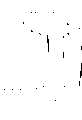
[图1]图1是技术方案1的螺栓的侧面图。[ Fig. 1] Fig. 1 is a side view of a bolt according to claim 1.
[图2]图2是显示螺栓杆部的前端部的一部分的放大图。[ Fig. 2] Fig. 2 is an enlarged view showing a part of a front end portion of a bolt shank.
[图3]图3是显示螺栓在倾斜情况下插入螺母的螺纹孔中的情况的一部分的剖面图。[ Fig. 3] Fig. 3 is a sectional view showing part of a state where a bolt is inserted into a threaded hole of a nut with an inclination.
[图4]图4是显示螺栓从图3情况下在右转方向转动60度的情况的一部分的剖面图。[ Fig. 4] Fig. 4 is a sectional view showing a part of a case where a bolt is turned 60 degrees in a clockwise direction from the case of Fig. 3 .
[图5]图5是技术方案2的螺栓的侧面图。[FIG. 5] FIG. 5 is a side view of the bolt of Claim 2. [FIG.
[图6]图6是显示图5的螺栓在倾斜情况下插入螺母的螺纹孔中的情况的一部分的剖面图。[ Fig. 6] Fig. 6 is a sectional view showing part of a state where the bolt of Fig. 5 is inserted into the threaded hole of the nut with an inclination.
[图7]图7是显示技术方案3的螺栓的杆部的前端部的一部分的放大图。[ Fig. 7] Fig. 7 is an enlarged view showing a part of a front end portion of a shank portion of a bolt according to claim 3 .
1:螺栓1: Bolt
10:头部10: head
15:杆部15: Rod
30:螺纹脊30: Thread Ridge
31:螺纹脊31: Thread Ridge
32:双螺纹的螺纹脊32: Double threaded thread ridge
115:定直径部分115: fixed diameter part
116:导引部分116: Guide part
126:无螺纹部分126: Unthreaded part
具体实施方式 Detailed ways
下文将结合附图介绍本发明的螺栓的第一实施例。首先,结合附图1和2介绍螺栓的结构。图1显示螺栓1上形成的经简化的螺纹。如图1和2所示,螺栓1由沿共同轴心延伸的基本六角形的柱状头部10和基本圆柱形的杆部15组成。杆部15的近端一侧形成具有恒定直径的圆柱形的定直径部分115,定直径部分115的外周表面上以预定螺距形成螺纹脊30。该螺纹脊30形成右旋螺纹结构,这样的螺纹结构在螺栓以右转方向转动(顺时针方向转动)时允许螺栓旋入母螺纹构件。杆部15的远端一侧形成具有比定直径部分115小的直径的圆柱形,当螺栓拧入后文介绍的螺母时,该远端部分作为将螺栓1的姿态正确导引到正确姿态的导引部分116。The first embodiment of the bolt of the present invention will be described below with reference to the accompanying drawings. First, the structure of the bolt is introduced in conjunction with accompanying drawings 1 and 2. FIG. 1 shows a simplified thread formed on a bolt 1 . As shown in Figures 1 and 2, the bolt 1 consists of a substantially hexagonal cylindrical head 10 and a substantially
在定直径部分115前端的规定范围,更具体地说,为大约3倍的螺纹脊30螺距长度的长度范围内,螺纹脊30的高度从杆部15的近端向前端逐渐降低,因此,通过连接螺纹脊30的脊顶形成的螺纹的外形形成大约15度锥角的锥形并且直径逐渐减小。应该注意,包括该部分的定直径部分115的根部的直径有恒定的尺寸。而且,基本截顶圆锥形的锥形部分117在导引部分116和定直径部分115之间形成在非常短的范围内。锥形部分117由具有与定直径部分115的根部直径相等的直径的圆形底部和具有与后文介绍的导引部分116的无螺纹部分的直径相等的直径的圆形顶部组成。锥形部分117的直径从所述底部向顶部以大约15度的锥角逐渐减小,而且在外周表面上没有形成螺纹脊。In the specified range of the front end of the
导引部分116从该锥形部分117的前端(顶部)向杆部15的前端延伸,近端一侧的一部分形成圆柱形的无螺纹部分126,无螺纹部分126上没有形成螺纹脊。更具体地说,在导引部分116的近端一侧,无螺纹部分126形成的长度基本是定直径部分115上形成的螺纹脊30的螺距长度的1.6倍,并且螺纹脊31形成在进一步的前端一侧的区域。螺纹脊31形成大约60度的脊角并具有与螺纹脊30相同的螺距。螺纹脊31的根部直径小于无螺纹部分126的直径,其外径大于无螺纹部分126的直径。应该注意,所形成的该外径小于螺栓1与其啮合的母螺纹构件的母螺纹部分的内径。导引部分116上形成的螺纹脊31形成与定直径部分115上形成的螺纹脊30相反的反向螺纹结构。也就是,当定直径部分115上的螺纹脊30是允许其自身以右转方向转动的右旋螺纹结构时,导引部分116上形成的螺纹脊31形成当螺栓1以右转方向转动时允许其自身从母螺纹构件中退出的左旋螺纹结构。The
接下来,结合附图3和4介绍将螺栓1和作为母螺纹构件的螺母100拧到一起的情况。如图3所示,螺母100允许右旋螺纹结构的公螺纹构件拧入螺母100,螺栓1在相对于螺母100倾斜一个角度时插入螺纹孔110,因此,在杆部15前端一侧的导引部分116上形成的螺纹脊31中,最顶部完整的螺纹脊与螺母100的内周表面上的母螺纹部分105相接合(啮合)。在这种情况下,在螺栓1插入一侧的螺母100的开口部分101的外周边缘上,螺栓1的定直径部分115前端的螺纹脊30在螺距偏离的情况下试图与螺母100的母螺纹部分105啮合。应该注意,在图中,螺母100的母螺纹部分105与螺栓1的定直径部分115前端的螺纹脊30重叠的情况意味着螺纹脊30处于由剖面表示的母螺纹部分105前的位置上。Next, the situation of screwing together the bolt 1 and the
当螺栓1转动(顺时针)以与螺母100啮合时,导引部分116随着螺栓1的顺时针转动以从螺母100的螺纹孔110中退出的方向移动,因为只有导引部分116上的螺纹脊31与螺母100的母螺纹部分105啮合,而且只要导引部分116上的螺纹脊31与母螺纹部分105啮合,即使只是稍许啮合,螺栓1也以从螺母100的螺纹孔110中退出的方向移动。虽然定直径部分115前端形成的螺纹脊30以及导引部分116上的螺纹脊31与母螺纹部分105相互干扰,但是定直径部分115前端的螺纹脊30的高度比定直径部分115其他部分的螺纹脊30的高度小,并且不会与母螺纹部分105啮合很深。因此,当螺栓1以退出的方向移动时,定直径部分115前端的螺纹脊30再也不会与母螺纹部分105啮合,并且螺栓1继续从螺纹孔110中顺利退出。而且,当螺栓1处于图中所示的情况下而且倾斜角更大,并且无螺纹部分126与螺母100的母螺纹部分105发生干扰时,螺栓1在导引部分116的螺纹脊31与母螺纹部分105啮合的部分之外的其他部分都再也不与螺母100啮合,由此螺栓1可以顺利地从螺纹孔110中退出。When the bolt 1 is rotated (clockwise) to engage with the
图4显示图3接下来的情况,其中导引部分116的螺纹脊31与母螺纹部分105啮合,螺栓1在紧固方向(右转方向)转动60度。如图4所示,可以确定导引部分116的螺纹脊31上的点M1和定直径部分115前端的螺纹脊30上的点N1分别转动60度,使螺栓以退出的方向移动,而且导引部分116上的螺纹脊31与母螺纹部分105啮合,所以螺栓1随着其转动以退出的方向移动。在图3中,定直径部分115前端的螺纹脊30与螺母100的母螺纹部分105重叠,并且在螺栓1转动60度后向上移动到螺母100的开口部分101附近,因此,螺纹脊30没有与螺母100的母螺纹部分105啮合,防止螺栓1和螺母100咬死或卡轧。FIG. 4 shows the situation following FIG. 3, wherein the threaded
虽然没有详细显示,当转动螺栓的工人把螺栓从倾斜状态恢复到竖直姿态时,螺栓1由于其自重以合适的姿态适配到螺母100的螺纹孔110中,这样螺栓1将被正常地拧紧。应该注意,螺纹脊31的外径需要形成得比母螺纹部分105的内径小,这样,当螺栓1调整到合适的螺旋姿态时,可以防止螺栓杆部15的导引部分116和螺母100的母螺纹部分105之间的干扰。当杆部15的导引部分116上形成的螺纹脊31没有与螺母100的内周表面上的母螺纹部分105配合(啮合)时,例如,如果导引部分116上形成的螺纹脊31刚与螺母100的内周表面上的母螺纹部分105发生干扰,螺栓1通过其自重以合适的姿态适配到螺母100的螺纹孔110中,之后螺栓1被正常地拧入螺母100中。Although not shown in detail, when the worker who turns the bolt restores the bolt from the inclined state to the vertical posture, the bolt 1 is fitted into the threaded
如上所述,在本实施例的螺栓1中,小直径的导引部分116形成在杆部15的远端,导引部分116上形成与定直径部分115上形成的螺纹脊30相反的反向螺纹结构的螺纹脊31。因此,在螺栓1相对于螺母100倾斜插入螺纹孔110的情况下,当导引部分116上的螺纹脊31与螺母100的母螺纹部分105啮合时,螺栓1以退出螺母100的方向移动,因为螺栓1没有处于合适的拧紧姿态。因此,除非螺栓1具有相对于螺母100合适的拧紧姿态,螺栓1无法旋入螺母中,因此,螺栓在不合适的情况例如在倾斜的情况下无法适配到螺母中,从而防止螺栓被咬死和卡轧在螺母中。As described above, in the bolt 1 of the present embodiment, the small-
虽然上述螺栓1的导引部分116的具有反向螺纹结构的螺纹脊31是单螺纹,但是导引部分116上可以形成具有反向螺纹结构的双螺纹的螺纹脊32。因为其他结构都相同,所以对应的部分都标以相同的参考数字并省略对其的叙述。Although the
当第二实施例的螺栓1以相对于螺母100倾斜的情形插入螺母100时,如图6所示,导引部分116上的具有反向螺纹结构的双螺纹的螺纹脊32与螺母100的母螺纹部分105啮合,从而使螺栓1处于浮动状态。然而,导引部分116上形成的螺纹脊32的行程量对应于螺栓1每转动一圈的两个螺距。因此,与导引部分116上形成的螺纹脊31是单螺纹的情况相比,退出的效果变为两倍。结果,除非螺栓1相对于螺母100设置成合适的拧紧姿态,螺栓1无法旋入螺母100中,从而可靠地防止被咬死和卡轧在螺母100中。When the bolt 1 of the second embodiment is inserted into the
接下来,参考附图7介绍本发明的螺栓的第二实施例。这里,除了杆部前端形成的导引部分外,螺栓200形成与上述实施例的螺栓1基本完全相同的结构。因此,下文只详细介绍螺栓200的杆部前端的形状。图7是显示螺栓200的杆部215的前端部的一部分的放大图,与螺栓1相同的参考数字标于与上述实施例的螺栓1共同的共用元件。如图7所示,螺栓200在杆部215的近端一侧具有定直径部分115,定直径部分115上形成右旋的螺纹脊30。螺纹脊30的高度在定直径部分115的前端部分逐渐降低,因此,通过连接螺纹脊30的脊顶产生的螺纹的外形是锥形的结构,其直径按大约15度的锥形角逐渐减小。Next, a second embodiment of the bolt of the present invention will be described with reference to FIG. 7 . Here, the
在螺栓200中,没有螺纹的无螺纹部分226从定直径部分115的前端延伸,与螺栓1不同。该无螺纹部分226具有与定直径部分115的根部基本完全相同的直径,而且进一步,截顶圆锥形的锥形部分217从无螺纹部分226前端延伸非常短的长度。具有比定直径部分115的根直径小得多的直径的导引部分216从锥形部分217的前端延伸。导引部分216上形成比螺栓1的导引部分116上形成的螺纹脊31低的螺纹脊231,而且螺纹脊231是相对于定直径部分115上的螺纹脊30的反向螺纹结构,也就是左旋螺纹结构。螺栓1的导引部分116上的螺纹脊31形成60度的脊角,而螺纹脊231形成90度的脊角。In the
当该实施例的螺栓200倾斜插入诸如螺母的母螺纹构件时,螺栓200可以可靠地防止卡轧现象发生。具体地,当螺栓200倾斜插入未显示的螺母的螺纹孔时,导引部分231上形成的螺纹脊216和螺母的母螺纹部分发生相互干扰。然而,与母螺纹部分的咬合浅,因为所形成的导引部分上的螺纹脊231的高度较低。因此,当该实施例的螺栓200在插入诸如螺母的母螺纹构件时能够抑制其倾斜,并且螺栓能够以合适的拧紧姿态可靠地旋入。应该注意,螺纹脊231可以是单螺纹的或双螺纹的结构。When the
如上所述,在本发明的螺栓中,定直径部分形成在杆部的近端一侧,具有较小直径的导引部分形成在前端一侧,与定直径部分上的螺纹脊相比,该导引部分上的螺纹脊形成反向螺纹结构。因此,当螺栓以不合适的姿态具体地在倾斜的情况下插入母螺纹构件时,该螺栓因为没有设置在合适的拧紧姿态而向母螺纹构件外移动。换句话说,因为除非螺栓相对于母螺纹构件设置到合适的拧紧姿态否则不能旋入,所以螺栓在不合适的姿态例如在倾斜的情形下无法适配到母螺纹构件中,可以可靠地防止螺栓被咬死或卡轧在母螺纹构件中。而且,可以通过将导引部分上的螺纹脊形成双螺纹结构加强该效果。在定直径部分和导引部分之间形成没有螺纹的无螺纹部分的情况下,当螺栓在倾斜情形下插入母螺纹构件时,即使无螺纹部分与母螺纹部分的内周表面发生相互干扰,无螺纹部分与母螺纹部分也从不会互相啮合,从而可以防止螺栓被咬死在母螺纹构件中。As described above, in the bolt of the present invention, the fixed-diameter portion is formed on the proximal side of the shank portion, and the guide portion having a smaller diameter is formed on the front-end side. Compared with the thread ridge on the fixed-diameter portion, the The thread ridges on the leading portion form reverse thread formations. Therefore, when a bolt is inserted into the female screw member with an improper posture, specifically with an inclination, the bolt moves outside the female screw member because it is not set in a proper tightening posture. In other words, since the bolt cannot be screwed in unless the bolt is set to an appropriate tightening posture with respect to the female threaded member, the bolt cannot be fitted into the female threaded member in an inappropriate posture such as in a tilted state, and the bolt can be reliably prevented from being screwed in. Being seized or stuck in the female threaded member. Furthermore, this effect can be enhanced by forming the thread ridge on the leading portion into a double thread structure. In the case where an unthreaded portion without thread is formed between the fixed diameter portion and the leading portion, when the bolt is inserted into the female threaded member in an inclined state, even if the unthreaded portion interferes with the inner peripheral surface of the female threaded portion, there is no The threaded portion and the female threaded portion never engage each other, thereby preventing the bolt from being seized in the female threaded member.
本发明不限于上述实施例而可以进行各种方式的修改。虽然在本实施例中螺母作为母螺纹构件的实例,但很自然本发明的螺栓也可以应用到其他母螺纹构件上。虽然在该实施例中,螺栓定直径部分上螺纹脊的高度逐渐降低的区域的长度,无螺纹部分的长度,锥形部分的长度等都举例说明,但是这些长度只是实例,不用说,这些部分可以形成上述实施例中所述之外的尺寸。另外,导引部分上形成的螺纹脊的形状和定直径部分上形成的螺纹脊的形状也不限于该实施例中的形状而可以进行合适的修改。The present invention is not limited to the above-described embodiments but can be modified in various ways. Although a nut is used as an example of a female threaded member in this embodiment, it is natural that the bolt of the present invention can also be applied to other female threaded members. Although in this embodiment, the length of the region where the height of the thread ridge on the fixed-diameter portion of the bolt gradually decreases, the length of the unthreaded portion, the length of the tapered portion, etc. are all exemplified, these lengths are only examples, and it goes without saying that these portions Dimensions other than those described in the above embodiments can be formed. In addition, the shape of the thread ridge formed on the guide portion and the shape of the thread ridge formed on the fixed-diameter portion are not limited to those in this embodiment and can be appropriately modified.
Claims (3)
Translated fromChineseApplications Claiming Priority (1)
| Application Number | Priority Date | Filing Date | Title |
|---|---|---|---|
| PCT/JP2005/010777WO2006134626A1 (en) | 2005-06-13 | 2005-06-13 | Bolt |
Publications (2)
| Publication Number | Publication Date |
|---|---|
| CN101208526Atrue CN101208526A (en) | 2008-06-25 |
| CN101208526B CN101208526B (en) | 2012-01-25 |
Family
ID=37531998
Family Applications (1)
| Application Number | Title | Priority Date | Filing Date |
|---|---|---|---|
| CN2005800501146AExpired - Fee RelatedCN101208526B (en) | 2005-06-13 | 2005-06-13 | Bolt |
Country Status (9)
| Country | Link |
|---|---|
| US (1) | US7866930B2 (en) |
| EP (1) | EP1892426B1 (en) |
| JP (1) | JP4968843B2 (en) |
| CN (1) | CN101208526B (en) |
| AT (1) | ATE519954T1 (en) |
| BR (1) | BRPI0520320B1 (en) |
| CA (1) | CA2608955C (en) |
| ES (1) | ES2369555T3 (en) |
| WO (1) | WO2006134626A1 (en) |
Cited By (7)
| Publication number | Priority date | Publication date | Assignee | Title |
|---|---|---|---|---|
| CN102171464B (en)* | 2008-10-02 | 2013-06-19 | 株式会社青山制作所 | Anti cross-thread bolt |
| CN103277386A (en)* | 2013-06-27 | 2013-09-04 | 余成鹏 | Convenient and stable thread structure |
| CN103990843A (en)* | 2014-05-13 | 2014-08-20 | 繁昌县金科机电科技有限公司 | Knife rest |
| CN104302932A (en)* | 2012-06-01 | 2015-01-21 | 株式会社青山制作所 | Anti-sintering bolts |
| CN109952442A (en)* | 2016-11-11 | 2019-06-28 | 株式会社明道 | Bolt |
| CN113272564A (en)* | 2019-01-11 | 2021-08-17 | 麦斯莱德有限公司 | Shortened fastener with locally controlled thread height |
| CN113544391A (en)* | 2019-02-22 | 2021-10-22 | 岩田螺丝株式会社 | Nut |
Families Citing this family (9)
| Publication number | Priority date | Publication date | Assignee | Title |
|---|---|---|---|---|
| CA2664591C (en)* | 2006-09-26 | 2014-12-02 | Synthes Usa, Llc | Transconnector |
| DE102008042141A1 (en)* | 2008-09-16 | 2010-03-25 | Kamax-Werke Rudolf Kellermann Gmbh & Co. Kg | Self-centering screw |
| WO2013030970A1 (en) | 2011-08-31 | 2013-03-07 | 株式会社青山製作所 | Anti-seizing nut |
| DE102011087178A1 (en)* | 2011-11-28 | 2013-05-29 | Hilti Aktiengesellschaft | Anchors, in particular rock anchors |
| US9835193B2 (en)* | 2014-05-01 | 2017-12-05 | Research Engineering & Manufacturing Inc. | Fastener system comprising an externally threaded bolt and an internally threaded nut for the avoidance of cross-threading of the mating threads during assembly |
| JP6382744B2 (en)* | 2015-02-23 | 2018-08-29 | 株式会社トープラ | Male thread member |
| KR101750004B1 (en)* | 2016-05-20 | 2017-07-03 | 신현우 | Tapping bolt with vertical support surface and manufacturing method for the same |
| US20180087555A1 (en)* | 2016-09-27 | 2018-03-29 | General Electric Company | System, method and apparatus for fastening components |
| IT201700077422A1 (en)* | 2017-07-10 | 2019-01-10 | Mr Ind Fasteners S R L | THREADED PIN |
Family Cites Families (17)
| Publication number | Priority date | Publication date | Assignee | Title |
|---|---|---|---|---|
| BE358225A (en)* | 1929-02-06 | |||
| US4018132A (en)* | 1974-06-18 | 1977-04-19 | Tokai Cold Forming Co., Ltd. | Connecting-rod bolt |
| GB1444885A (en)* | 1975-02-06 | 1976-08-04 | Vibro Loc Co Ltd | Nuts and bolts |
| JPH01182613A (en) | 1988-01-16 | 1989-07-20 | Toopura:Kk | Screw with pilot |
| JPH1073118A (en) | 1996-08-28 | 1998-03-17 | Mino Kogyo Kk | Bolt and nut |
| WO1999031395A1 (en)* | 1997-12-16 | 1999-06-24 | Sfs Industrie Holding Ag | Screw for fixing the distance of covering plates or rails in a substructure |
| JPH11182521A (en) | 1997-12-24 | 1999-07-06 | Owari Precise Products Co Ltd | Screw |
| CN2367823Y (en)* | 1998-03-04 | 2000-03-08 | 马荣生 | Anti-loose screw bolt |
| JP3336257B2 (en) | 1998-07-07 | 2002-10-21 | 株式会社青山製作所 | bolt |
| JP2000274417A (en)* | 1999-03-24 | 2000-10-03 | Namie Kato | Unfastened nut and bolt |
| US6125526A (en)* | 1999-05-12 | 2000-10-03 | Robert Bosch Corporation | Method of fastening a first member to a second member |
| JP2002195230A (en) | 2000-12-26 | 2002-07-10 | Aoyama Seisakusho Co Ltd | bolt |
| US6666638B2 (en)* | 2001-02-15 | 2003-12-23 | Phillips Screw Company | Deck screw having multiple threaded sections |
| JP4171631B2 (en)* | 2001-09-25 | 2008-10-22 | 株式会社青山製作所 | bolt |
| US6918727B2 (en)* | 2002-05-01 | 2005-07-19 | Joker Industrial Co., Ltd. | Anchoring screw with double heads and triple threads of different depths of thread |
| US7213999B2 (en)* | 2004-01-30 | 2007-05-08 | Torque-Traction Technologies, Llc. | Fastener with opposite hand threads for securing two components together |
| US20070217887A1 (en)* | 2006-03-16 | 2007-09-20 | Ching-Kuei Lin | Screw |
- 2005
- 2005-06-13EPEP05748628Apatent/EP1892426B1/ennot_activeExpired - Lifetime
- 2005-06-13USUS11/914,660patent/US7866930B2/ennot_activeExpired - Fee Related
- 2005-06-13ATAT05748628Tpatent/ATE519954T1/ennot_activeIP Right Cessation
- 2005-06-13JPJP2007521020Apatent/JP4968843B2/ennot_activeExpired - Lifetime
- 2005-06-13ESES05748628Tpatent/ES2369555T3/ennot_activeExpired - Lifetime
- 2005-06-13CNCN2005800501146Apatent/CN101208526B/ennot_activeExpired - Fee Related
- 2005-06-13WOPCT/JP2005/010777patent/WO2006134626A1/enactiveApplication Filing
- 2005-06-13CACA2608955Apatent/CA2608955C/ennot_activeExpired - Fee Related
- 2005-06-13BRBRPI0520320-1Apatent/BRPI0520320B1/ennot_activeIP Right Cessation
Cited By (10)
| Publication number | Priority date | Publication date | Assignee | Title |
|---|---|---|---|---|
| CN102171464B (en)* | 2008-10-02 | 2013-06-19 | 株式会社青山制作所 | Anti cross-thread bolt |
| CN104302932A (en)* | 2012-06-01 | 2015-01-21 | 株式会社青山制作所 | Anti-sintering bolts |
| CN103277386A (en)* | 2013-06-27 | 2013-09-04 | 余成鹏 | Convenient and stable thread structure |
| CN103990843A (en)* | 2014-05-13 | 2014-08-20 | 繁昌县金科机电科技有限公司 | Knife rest |
| CN109952442A (en)* | 2016-11-11 | 2019-06-28 | 株式会社明道 | Bolt |
| US11209038B2 (en) | 2016-11-11 | 2021-12-28 | Meidoh Co., Ltd. | Bolt |
| CN113272564A (en)* | 2019-01-11 | 2021-08-17 | 麦斯莱德有限公司 | Shortened fastener with locally controlled thread height |
| US11815121B2 (en) | 2019-01-11 | 2023-11-14 | Mathread, Inc. | Shortened fastener with locally controlled thread height |
| CN113544391A (en)* | 2019-02-22 | 2021-10-22 | 岩田螺丝株式会社 | Nut |
| CN113544391B (en)* | 2019-02-22 | 2023-08-25 | 岩田螺丝株式会社 | nut |
Also Published As
| Publication number | Publication date |
|---|---|
| ATE519954T1 (en) | 2011-08-15 |
| BRPI0520320A2 (en) | 2009-09-15 |
| JP4968843B2 (en) | 2012-07-04 |
| US20090060676A1 (en) | 2009-03-05 |
| CA2608955A1 (en) | 2006-12-21 |
| EP1892426A1 (en) | 2008-02-27 |
| WO2006134626A1 (en) | 2006-12-21 |
| BRPI0520320B1 (en) | 2018-02-14 |
| JPWO2006134626A1 (en) | 2009-01-08 |
| CA2608955C (en) | 2011-02-08 |
| ES2369555T3 (en) | 2011-12-01 |
| EP1892426A4 (en) | 2009-02-25 |
| EP1892426B1 (en) | 2011-08-10 |
| US7866930B2 (en) | 2011-01-11 |
| CN101208526B (en) | 2012-01-25 |
Similar Documents
| Publication | Publication Date | Title |
|---|---|---|
| CN101208526A (en) | bolt | |
| EP1296070B1 (en) | Bolt and nut | |
| US8632288B2 (en) | Anti cross-thread bolt | |
| US10527081B2 (en) | Tapered internal thread and threaded column connecting structure | |
| US10690170B2 (en) | Fastener system comprising an externally threaded bolt and an internally threaded nut for the avoidance of cross-threading of the mating threads during assembly | |
| CN108350921B (en) | Screw, in particular for use in light metal, for forming or tapping | |
| TWI622710B (en) | Screw for a thin iron plate | |
| US10508677B2 (en) | Tapered thread connection pair | |
| EP3808999B1 (en) | Male threaded member | |
| JP6676113B2 (en) | Male thread member | |
| WO2013030970A1 (en) | Anti-seizing nut | |
| CN113251054B (en) | External screw member | |
| JP2018189244A5 (en) | ||
| JP2016156400A5 (en) | ||
| JP4466994B2 (en) | Bite prevention bolt | |
| JPH11351222A (en) | Improved screw fastener preventing oblique screw-in | |
| JP2009264459A (en) | Nut | |
| JP2007187305A (en) | Pilot hole shape for tapping screws | |
| EP3604834A1 (en) | Bolt | |
| JP2006161903A (en) | Tapping screw | |
| TH29567B (en) | Male screw piece |
Legal Events
| Date | Code | Title | Description |
|---|---|---|---|
| C06 | Publication | ||
| PB01 | Publication | ||
| C10 | Entry into substantive examination | ||
| SE01 | Entry into force of request for substantive examination | ||
| C14 | Grant of patent or utility model | ||
| GR01 | Patent grant | ||
| CF01 | Termination of patent right due to non-payment of annual fee | Granted publication date:20120125 Termination date:20200613 | |
| CF01 | Termination of patent right due to non-payment of annual fee |