CN101208522A - water pump impeller - Google Patents
water pump impellerDownload PDFInfo
- Publication number
- CN101208522A CN101208522ACNA2006800232411ACN200680023241ACN101208522ACN 101208522 ACN101208522 ACN 101208522ACN A2006800232411 ACNA2006800232411 ACN A2006800232411ACN 200680023241 ACN200680023241 ACN 200680023241ACN 101208522 ACN101208522 ACN 101208522A
- Authority
- CN
- China
- Prior art keywords
- impeller
- rear wall
- guide vane
- wheel hub
- molding plate
- Prior art date
- Legal status (The legal status is an assumption and is not a legal conclusion. Google has not performed a legal analysis and makes no representation as to the accuracy of the status listed.)
- Granted
Links
Images


Classifications
- B—PERFORMING OPERATIONS; TRANSPORTING
- B29—WORKING OF PLASTICS; WORKING OF SUBSTANCES IN A PLASTIC STATE IN GENERAL
- B29C—SHAPING OR JOINING OF PLASTICS; SHAPING OF MATERIAL IN A PLASTIC STATE, NOT OTHERWISE PROVIDED FOR; AFTER-TREATMENT OF THE SHAPED PRODUCTS, e.g. REPAIRING
- B29C66/00—General aspects of processes or apparatus for joining preformed parts
- B29C66/50—General aspects of joining tubular articles; General aspects of joining long products, i.e. bars or profiled elements; General aspects of joining single elements to tubular articles, hollow articles or bars; General aspects of joining several hollow-preforms to form hollow or tubular articles
- B29C66/51—Joining tubular articles, profiled elements or bars; Joining single elements to tubular articles, hollow articles or bars; Joining several hollow-preforms to form hollow or tubular articles
- B29C66/54—Joining several hollow-preforms, e.g. half-shells, to form hollow articles, e.g. for making balls, containers; Joining several hollow-preforms, e.g. half-cylinders, to form tubular articles
- B—PERFORMING OPERATIONS; TRANSPORTING
- B29—WORKING OF PLASTICS; WORKING OF SUBSTANCES IN A PLASTIC STATE IN GENERAL
- B29C—SHAPING OR JOINING OF PLASTICS; SHAPING OF MATERIAL IN A PLASTIC STATE, NOT OTHERWISE PROVIDED FOR; AFTER-TREATMENT OF THE SHAPED PRODUCTS, e.g. REPAIRING
- B29C65/00—Joining or sealing of preformed parts, e.g. welding of plastics materials; Apparatus therefor
- B29C65/48—Joining or sealing of preformed parts, e.g. welding of plastics materials; Apparatus therefor using adhesives, i.e. using supplementary joining material; solvent bonding
- B—PERFORMING OPERATIONS; TRANSPORTING
- B29—WORKING OF PLASTICS; WORKING OF SUBSTANCES IN A PLASTIC STATE IN GENERAL
- B29C—SHAPING OR JOINING OF PLASTICS; SHAPING OF MATERIAL IN A PLASTIC STATE, NOT OTHERWISE PROVIDED FOR; AFTER-TREATMENT OF THE SHAPED PRODUCTS, e.g. REPAIRING
- B29C65/00—Joining or sealing of preformed parts, e.g. welding of plastics materials; Apparatus therefor
- B29C65/78—Means for handling the parts to be joined, e.g. for making containers or hollow articles, e.g. means for handling sheets, plates, web-like materials, tubular articles, hollow articles or elements to be joined therewith; Means for discharging the joined articles from the joining apparatus
- B29C65/7802—Positioning the parts to be joined, e.g. aligning, indexing or centring
- B29C65/7805—Positioning the parts to be joined, e.g. aligning, indexing or centring the parts to be joined comprising positioning features
- B29C65/7814—Positioning the parts to be joined, e.g. aligning, indexing or centring the parts to be joined comprising positioning features in the form of inter-cooperating positioning features, e.g. tenons and mortises
- B—PERFORMING OPERATIONS; TRANSPORTING
- B29—WORKING OF PLASTICS; WORKING OF SUBSTANCES IN A PLASTIC STATE IN GENERAL
- B29C—SHAPING OR JOINING OF PLASTICS; SHAPING OF MATERIAL IN A PLASTIC STATE, NOT OTHERWISE PROVIDED FOR; AFTER-TREATMENT OF THE SHAPED PRODUCTS, e.g. REPAIRING
- B29C66/00—General aspects of processes or apparatus for joining preformed parts
- B29C66/01—General aspects dealing with the joint area or with the area to be joined
- B29C66/05—Particular design of joint configurations
- B29C66/10—Particular design of joint configurations particular design of the joint cross-sections
- B29C66/11—Joint cross-sections comprising a single joint-segment, i.e. one of the parts to be joined comprising a single joint-segment in the joint cross-section
- B29C66/112—Single lapped joints
- B—PERFORMING OPERATIONS; TRANSPORTING
- B29—WORKING OF PLASTICS; WORKING OF SUBSTANCES IN A PLASTIC STATE IN GENERAL
- B29C—SHAPING OR JOINING OF PLASTICS; SHAPING OF MATERIAL IN A PLASTIC STATE, NOT OTHERWISE PROVIDED FOR; AFTER-TREATMENT OF THE SHAPED PRODUCTS, e.g. REPAIRING
- B29C66/00—General aspects of processes or apparatus for joining preformed parts
- B29C66/01—General aspects dealing with the joint area or with the area to be joined
- B29C66/05—Particular design of joint configurations
- B29C66/10—Particular design of joint configurations particular design of the joint cross-sections
- B29C66/11—Joint cross-sections comprising a single joint-segment, i.e. one of the parts to be joined comprising a single joint-segment in the joint cross-section
- B29C66/116—Single bevelled joints, i.e. one of the parts to be joined being bevelled in the joint area
- B—PERFORMING OPERATIONS; TRANSPORTING
- B29—WORKING OF PLASTICS; WORKING OF SUBSTANCES IN A PLASTIC STATE IN GENERAL
- B29C—SHAPING OR JOINING OF PLASTICS; SHAPING OF MATERIAL IN A PLASTIC STATE, NOT OTHERWISE PROVIDED FOR; AFTER-TREATMENT OF THE SHAPED PRODUCTS, e.g. REPAIRING
- B29C66/00—General aspects of processes or apparatus for joining preformed parts
- B29C66/01—General aspects dealing with the joint area or with the area to be joined
- B29C66/05—Particular design of joint configurations
- B29C66/10—Particular design of joint configurations particular design of the joint cross-sections
- B29C66/13—Single flanged joints; Fin-type joints; Single hem joints; Edge joints; Interpenetrating fingered joints; Other specific particular designs of joint cross-sections not provided for in groups B29C66/11 - B29C66/12
- B29C66/131—Single flanged joints, i.e. one of the parts to be joined being rigid and flanged in the joint area
- B—PERFORMING OPERATIONS; TRANSPORTING
- B29—WORKING OF PLASTICS; WORKING OF SUBSTANCES IN A PLASTIC STATE IN GENERAL
- B29C—SHAPING OR JOINING OF PLASTICS; SHAPING OF MATERIAL IN A PLASTIC STATE, NOT OTHERWISE PROVIDED FOR; AFTER-TREATMENT OF THE SHAPED PRODUCTS, e.g. REPAIRING
- B29C66/00—General aspects of processes or apparatus for joining preformed parts
- B29C66/50—General aspects of joining tubular articles; General aspects of joining long products, i.e. bars or profiled elements; General aspects of joining single elements to tubular articles, hollow articles or bars; General aspects of joining several hollow-preforms to form hollow or tubular articles
- B29C66/51—Joining tubular articles, profiled elements or bars; Joining single elements to tubular articles, hollow articles or bars; Joining several hollow-preforms to form hollow or tubular articles
- B29C66/53—Joining single elements to tubular articles, hollow articles or bars
- B29C66/534—Joining single elements to open ends of tubular or hollow articles or to the ends of bars
- B29C66/5344—Joining single elements to open ends of tubular or hollow articles or to the ends of bars said single elements being substantially annular, i.e. of finite length, e.g. joining flanges to tube ends
- B—PERFORMING OPERATIONS; TRANSPORTING
- B29—WORKING OF PLASTICS; WORKING OF SUBSTANCES IN A PLASTIC STATE IN GENERAL
- B29C—SHAPING OR JOINING OF PLASTICS; SHAPING OF MATERIAL IN A PLASTIC STATE, NOT OTHERWISE PROVIDED FOR; AFTER-TREATMENT OF THE SHAPED PRODUCTS, e.g. REPAIRING
- B29C66/00—General aspects of processes or apparatus for joining preformed parts
- B29C66/70—General aspects of processes or apparatus for joining preformed parts characterised by the composition, physical properties or the structure of the material of the parts to be joined; Joining with non-plastics material
- B29C66/71—General aspects of processes or apparatus for joining preformed parts characterised by the composition, physical properties or the structure of the material of the parts to be joined; Joining with non-plastics material characterised by the composition of the plastics material of the parts to be joined
- F—MECHANICAL ENGINEERING; LIGHTING; HEATING; WEAPONS; BLASTING
- F04—POSITIVE - DISPLACEMENT MACHINES FOR LIQUIDS; PUMPS FOR LIQUIDS OR ELASTIC FLUIDS
- F04D—NON-POSITIVE-DISPLACEMENT PUMPS
- F04D29/00—Details, component parts, or accessories
- F04D29/18—Rotors
- F04D29/22—Rotors specially for centrifugal pumps
- F04D29/2205—Conventional flow pattern
- F04D29/2222—Construction and assembly
- F04D29/2227—Construction and assembly for special materials
- B—PERFORMING OPERATIONS; TRANSPORTING
- B29—WORKING OF PLASTICS; WORKING OF SUBSTANCES IN A PLASTIC STATE IN GENERAL
- B29C—SHAPING OR JOINING OF PLASTICS; SHAPING OF MATERIAL IN A PLASTIC STATE, NOT OTHERWISE PROVIDED FOR; AFTER-TREATMENT OF THE SHAPED PRODUCTS, e.g. REPAIRING
- B29C65/00—Joining or sealing of preformed parts, e.g. welding of plastics materials; Apparatus therefor
- B29C65/02—Joining or sealing of preformed parts, e.g. welding of plastics materials; Apparatus therefor by heating, with or without pressure
- B29C65/08—Joining or sealing of preformed parts, e.g. welding of plastics materials; Apparatus therefor by heating, with or without pressure using ultrasonic vibrations
- B—PERFORMING OPERATIONS; TRANSPORTING
- B29—WORKING OF PLASTICS; WORKING OF SUBSTANCES IN A PLASTIC STATE IN GENERAL
- B29C—SHAPING OR JOINING OF PLASTICS; SHAPING OF MATERIAL IN A PLASTIC STATE, NOT OTHERWISE PROVIDED FOR; AFTER-TREATMENT OF THE SHAPED PRODUCTS, e.g. REPAIRING
- B29C65/00—Joining or sealing of preformed parts, e.g. welding of plastics materials; Apparatus therefor
- B29C65/48—Joining or sealing of preformed parts, e.g. welding of plastics materials; Apparatus therefor using adhesives, i.e. using supplementary joining material; solvent bonding
- B29C65/4805—Joining or sealing of preformed parts, e.g. welding of plastics materials; Apparatus therefor using adhesives, i.e. using supplementary joining material; solvent bonding characterised by the type of adhesives
- B29C65/483—Reactive adhesives, e.g. chemically curing adhesives
- B29C65/484—Moisture curing adhesives
- B—PERFORMING OPERATIONS; TRANSPORTING
- B29—WORKING OF PLASTICS; WORKING OF SUBSTANCES IN A PLASTIC STATE IN GENERAL
- B29K—INDEXING SCHEME ASSOCIATED WITH SUBCLASSES B29B, B29C OR B29D, RELATING TO MOULDING MATERIALS OR TO MATERIALS FOR MOULDS, REINFORCEMENTS, FILLERS OR PREFORMED PARTS, e.g. INSERTS
- B29K2025/00—Use of polymers of vinyl-aromatic compounds or derivatives thereof as moulding material
- B—PERFORMING OPERATIONS; TRANSPORTING
- B29—WORKING OF PLASTICS; WORKING OF SUBSTANCES IN A PLASTIC STATE IN GENERAL
- B29L—INDEXING SCHEME ASSOCIATED WITH SUBCLASS B29C, RELATING TO PARTICULAR ARTICLES
- B29L2031/00—Other particular articles
- B29L2031/08—Blades for rotors, stators, fans, turbines or the like, e.g. screw propellers
- B29L2031/087—Propellers
- B—PERFORMING OPERATIONS; TRANSPORTING
- B29—WORKING OF PLASTICS; WORKING OF SUBSTANCES IN A PLASTIC STATE IN GENERAL
- B29L—INDEXING SCHEME ASSOCIATED WITH SUBCLASS B29C, RELATING TO PARTICULAR ARTICLES
- B29L2031/00—Other particular articles
- B29L2031/748—Machines or parts thereof not otherwise provided for
- B29L2031/7496—Pumps
- F—MECHANICAL ENGINEERING; LIGHTING; HEATING; WEAPONS; BLASTING
- F05—INDEXING SCHEMES RELATING TO ENGINES OR PUMPS IN VARIOUS SUBCLASSES OF CLASSES F01-F04
- F05D—INDEXING SCHEME FOR ASPECTS RELATING TO NON-POSITIVE-DISPLACEMENT MACHINES OR ENGINES, GAS-TURBINES OR JET-PROPULSION PLANTS
- F05D2300/00—Materials; Properties thereof
- F05D2300/40—Organic materials
- F05D2300/43—Synthetic polymers, e.g. plastics; Rubber
- Y—GENERAL TAGGING OF NEW TECHNOLOGICAL DEVELOPMENTS; GENERAL TAGGING OF CROSS-SECTIONAL TECHNOLOGIES SPANNING OVER SEVERAL SECTIONS OF THE IPC; TECHNICAL SUBJECTS COVERED BY FORMER USPC CROSS-REFERENCE ART COLLECTIONS [XRACs] AND DIGESTS
- Y10—TECHNICAL SUBJECTS COVERED BY FORMER USPC
- Y10T—TECHNICAL SUBJECTS COVERED BY FORMER US CLASSIFICATION
- Y10T29/00—Metal working
- Y10T29/49—Method of mechanical manufacture
- Y10T29/49316—Impeller making
- Y10T29/49332—Propeller making
Landscapes
- Engineering & Computer Science (AREA)
- Mechanical Engineering (AREA)
- General Engineering & Computer Science (AREA)
- Structures Of Non-Positive Displacement Pumps (AREA)
Abstract
Translated fromChineseDescription
Translated fromChinese技术领域technical field
本发明的主题是特别是用于内燃机的冷却剂泵的由塑料制成的叶轮。被构造为注塑件的叶轮包括带有中心轮毂的后壁或底部,叶轮通过该轮毂置于轴上。后壁在前侧一体地设有导向叶片。在与后壁背离的一侧,导向叶片在前侧被模制盘局部覆盖,由此在叶轮内部形成中空室,这些中空室由各个导向叶片或后壁和模制盘限定。The subject of the invention is an impeller made of plastic, in particular for a coolant pump of an internal combustion engine. The impeller, which is constructed as an injection-molded part, has a rear wall or bottom with a central hub, by means of which the impeller rests on the shaft. The rear wall is integrally provided with guide vanes on the front side. On the side facing away from the rear wall, the guide vanes are partially covered on the front side by the molded disk, so that hollow spaces are formed inside the impeller, which are delimited by the individual guide vanes or rear wall and the molded disk.
背景技术Background technique
用于内燃机的冷却剂泵的叶轮优选由塑料制成,用于实现可成本低廉地制造的且重量最佳的部件。这种冷却剂泵的叶轮优选被设计用于使冷却剂在轴向流入,冷却剂被换向地在径向从叶轮中流出。为此,叶轮设有多个沿着径向或者轴向-径向弯曲的导向叶片,这些导向叶片与叶轮的后壁一体连接。The impeller of a coolant pump for an internal combustion engine is preferably made of plastic in order to achieve a cost-effectively producible and weight-optimized component. The impeller of such a coolant pump is preferably designed to allow coolant to flow in axially and for the coolant to flow radially out of the impeller in a reversed manner. For this purpose, the impeller is provided with a plurality of radially or axially-radially curved guide vanes which are integrally connected to the rear wall of the impeller.
前述结构类型的叶轮由DE 38 39 860 A1已知。为了实现叶轮和冷却剂泵的驱动轴之间的形锁合的连接,叶轮的中心区段具有轴向突出的带有多边形断面的接管。在安装状态下,该接管形锁合地嵌入到单独的螺杆或泵轴的接纳件中。其中接纳件的横截面与轴向突出的接管的横截面相对应。不利的是,安装包括多个单个部件的叶轮比较费劲。An impeller of the aforementioned construction type is known from DE 38 39 860 A1. In order to achieve a positive connection between the impeller and the drive shaft of the coolant pump, the central section of the impeller has an axially protruding socket with a polygonal cross-section. In the assembled state, the socket engages in a form-fitting manner in a separate screw or receptacle for the pump shaft. In this case, the cross-section of the receiving part corresponds to the cross-section of the axially protruding socket. Disadvantageously, mounting an impeller comprising a number of individual parts is relatively labor-intensive.
发明内容Contents of the invention
本发明的目的在于,提出一种成本最佳的、强度提高的塑料叶轮,安装该叶轮并不费劲。The object of the present invention is to provide a cost-optimized impeller made of plastic with increased strength, which is easy to install.
本发明的目的通过独立权利要求1、2和11的特征得以实现。The objects of the invention are achieved by the features of
本发明一致地使用热塑性的塑料间同立构聚苯乙烯(PS-S-GF 30)。这种成本低廉的材料可以理想地用于冷却剂泵的叶轮。其中这种塑料具有相对于内燃机中所使用的所有冷却剂的提高的稳定性,由此不易破裂。此外根据本发明的热塑性塑料可以在内燃机中的冷却剂的整个温度范围内使用。由间同立构聚苯乙烯PS-S-GF 30构成的本发明的叶轮的前述正面的材料特性已通过专门的化合得以实现。有益的是,可以使用已有的工具、即注塑装置来处理根据本发明所使用的热塑性塑料,因此材料更换不会由于新的或待适配的工具装置而对制造成本产生影响。材料PS-S-GF 30有利地防止在迄今所使用的塑料的情况下出现的工具腐蚀,工具腐蚀需要麻烦且昂贵的工具涂层。The present invention consistently uses the thermoplastic syndiotactic polystyrene (PS-S-GF 30). This inexpensive material is ideal for impellers in coolant pumps. In this case, plastics of this type have increased stability relative to all coolants used in internal combustion engines and are therefore less prone to breakage. Furthermore, the thermoplastics according to the invention can be used in the entire temperature range of the coolant in the internal combustion engine. The aforementioned material properties of the front face of the inventive impeller made of syndiotactic polystyrene PS-S-GF 30 have been achieved by special compounding. Advantageously, existing tools, ie injection molding devices, can be used for processing the thermoplastics used according to the invention, so that material changes do not have an impact on production costs due to new or to-be-adapted tool devices. The material PS-S-GF 30 advantageously prevents the tool corrosion which occurs with the plastics used so far, which requires complicated and expensive tool coatings.
根据本发明所使用的间同立构聚苯乙烯具有显著的材料特性。因此很小的水分吸收能力允许技术上简单的处理。此外,这种材料的特征还在于非常小的热膨胀系数。附加地,PS-S-GF 30由于其良好的流动特性可以实现采用注射成型工艺来制造壁厚较薄的部件。具有高流动性的低粘性的塑料与迄今所使用的塑料相比只需很小的注塑压力,由此可以由PS-S-GF 30成本低廉地在具有较小合型力的注射成型机上制造叶轮。The syndiotactic polystyrene used according to the invention has outstanding material properties. The low moisture absorption capacity thus allows technically simple handling. Furthermore, this material is also characterized by a very low coefficient of thermal expansion. Additionally, PS-S-GF 30, due to its good flow characteristics, can be used to manufacture parts with thinner walls by injection molding. The highly fluid, low-viscosity plastic requires lower injection pressures than previously used plastics and can thus be produced cost-effectively from the PS-S-GF 30 on injection molding machines with low closing forces impeller.
由于PS-S-GF 30的密度小(≤1.35g/cm3),所以可附加地实现材料节省。对于用于就冷却剂泵公知的轿车内燃机的叶轮来说,可以通过使用PS-S-GF 30有益地实现≥24%的重量节省。由PS-S-GF 30制成的叶轮的特征在于其形状稳定、不易变形以及所希望的低于迄今所使用塑料的加工温度。Due to the low density of PS-S-GF 30 (≦1.35 g/cm3 ), material savings can additionally be achieved. For impellers for passenger cars internal combustion engines known for coolant pumps, a weight saving of ≧24% can advantageously be achieved by using PS-S-GF 30 . Impellers made of PS-S-GF 30 are distinguished by their shape stability, low deformation and, hopefully, lower processing temperatures than the plastics used hitherto.
为了制造塑料叶轮,通过用本发明所使用的间同立构聚苯乙烯来代替迄今所使用的塑料PPS-GF40,有益地降低了叶轮成本,而不会不利地影响叶轮的强度、化学稳定性或寿命。In order to manufacture the plastic impeller, by replacing the plastic PPS-GF40 used so far with the syndiotactic polystyrene used in the present invention, the cost of the impeller is beneficially reduced without adversely affecting the strength, chemical stability of the impeller or lifespan.
根据权利要求1的本发明涉及包括多个部件的叶轮,其中各个单独制造的部件,特别是包括轮毂及配设的导向叶片的后壁以及模制盘材料锁合地组装在一起。The invention according to
根据权利要求2的本发明涉及一种一体设计的具有侧凹部的叶轮,其中使用热塑性塑料间同立构聚苯乙烯PS-S-GF 30作为材料。有益的是,对于一体的叶轮来说,根据本发明更换材料也决不需要适配或改变滑板工具(Schieberwerkzeug)或用于制造的注射成型工艺。The invention according to
根据权利要求11的本发明涉及一种方法,该方法要求保护制造工序和安装步骤,根据这种方法可制造多件式结构的叶轮。有益地以如下步骤制造多件式结构的叶轮。首先在分开的注塑过程中制造各部件,即一方面为包括轮毂及配设的导向叶片在内的后壁,以及另一方面为模制盘。在后壁的导向叶片上轴向突出的榫舌或凸耳和模制盘的对应的凹槽之间的接合区域中至少在一个接触区域上敷设胶粘剂。为了实现材料锁合的连接,接着对这些部件进行接合和短时间的压紧。在后壁区域中的轮毂的中心孔用于容纳单独的轴套,该轴套同样通过粘接材料锁合地固定。The invention according to
本发明的其它有益的实施形式是从属权利要求3至10的主题。Further advantageous embodiments of the invention are the subject matter of
为了实现对多件式结构的叶轮的所有部件的材料锁合的连接,优选进行粘接。由此可以实现比迄今所使用的超声波焊接方法或UV焊接方法高的制造精度。有益地可以在粘接时省去对叶轮的对中,因为对中在工具内部进行。由于改善的公差小的制造精度,所以可以通过粘接实现改善的转动。因此即使对于大尺寸的叶轮或者高转速的叶轮来说,仍可实现足够的转动精确性,而无需附加的平衡。Gluing is preferably carried out in order to achieve a materially bonded connection of all parts of the multi-part impeller. This makes it possible to achieve a higher manufacturing accuracy than the ultrasonic welding methods or UV welding methods used so far. Advantageously, the centering of the impeller can be dispensed with during gluing, since the centering takes place inside the tool. Due to the improved manufacturing precision with tight tolerances, an improved rotation can be achieved by bonding. Sufficient rotational accuracy can thus be achieved even with large-sized impellers or impellers with high rotational speeds without additional balancing.
根据对包括多个单个部件的叶轮的一种优选的设计,导向叶片包括与模制盘的相应的凹槽对应的、局部突出的凸耳或榫舌在安装状态下,通过形锁合地嵌入到凹槽中的榫舌对模制盘进行对中,其中在榫舌和凹槽之间的接触区中的粘接使这些部件相连接。According to a preferred design of the impeller comprising a plurality of individual parts, the guide vanes comprise locally protruding lugs or tongues corresponding to corresponding grooves of the molded disc. The tongue into the groove centers the molded disc, wherein the bonding in the contact area between the tongue and the groove connects the parts.
为了实现对部件即后壁和模制盘的材料锁合的连接,根据本发明优选使用氰基丙烯酸酯、环氧树脂或合成橡胶作为合适的胶粘剂。为了实现粘接,在所述部件相互接合之前,在轴向突出的榫舌和模制盘的凹槽之间的接合区域中,在至少一个部件上敷设胶粘剂,并结合有限时间的压紧。In order to achieve a materially bonded connection of the components, namely the rear wall and the molded plate, cyanoacrylates, epoxy resins or synthetic rubbers are preferably used as suitable adhesives according to the invention. To achieve bonding, adhesive is applied on at least one part in the joint area between the axially protruding tongue and the groove of the molded disc, in combination with time-limited pressing, before said parts are mutually joined.
本发明的叶轮附加地具有一个单独的轴套,该轴套定位在轮毂的中心孔中,由此定位在后壁的中心孔中。其中由金属材料或塑料制成的圆筒形的轴套同样通过粘接位置固定在轮毂中。在安装状态下,叶轮例如通过压配合而抗旋转地固定在轴套和叶轮轴之间。The impeller according to the invention additionally has a separate bushing which is positioned in the central hole of the hub and thus in the central hole of the rear wall. In this case, the cylindrical bushing made of metallic material or plastic is likewise fixed in the hub by means of adhesive joints. In the mounted state, the impeller is fixed in a rotationally fixed manner, for example by means of a press fit, between the bushing and the impeller shaft.
作为对单独的轴套的替代方案,本发明包括由热塑性塑料制成的叶轮,该叶轮的轮毂直接地、即无需单独的轴套地通过压配合和/或粘接抗旋转地固定在叶轮的轴上。As an alternative to a separate bushing, the invention consists of an impeller made of thermoplastic, the hub of which is fixed directly, that is, without a separate bushing, by force fitting and/or adhesively fixed to the impeller's hub. on axis.
根据本发明用于冷却剂泵的叶轮的热塑性塑料是米色的。由此可以在迄今暗色的由PPS制成的叶轮之间与本发明的米色叶轮比较得到明显的区分。The thermoplastic used according to the invention for the impeller of the coolant pump is beige. A clear distinction can thus be drawn between the previously dark-coloured impellers made of PPS in comparison with the beige impeller according to the invention.
为了实现一体结构的叶轮,可以将轴套作为插入部件插入到在注塑过程中被叶轮的塑料PS-S-GF 30包围的注塑工具中,用于实现抗旋转的连接。In order to realize a one-piece impeller, the bushing can be inserted as an insert part into the injection molding tool which is surrounded by the impeller's plastic PS-S-GF 30 during the injection molding process for a rotation-resistant connection.
此外本发明包括一种其导向叶片三维(3D)弯曲的叶轮。Furthermore, the invention includes an impeller whose guide blades are three-dimensionally (3D) curved.
本发明的其它特征可以从下面的对附图的说明得到,图中示出本发明的实施例。Further features of the invention can be taken from the following description of the drawing, which shows an exemplary embodiment of the invention.
附图说明Description of drawings
图中示出:The figure shows:
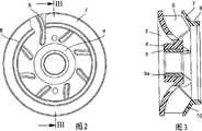
图1为本发明的叶轮结合轴的立体图;Fig. 1 is the perspective view of the impeller coupling shaft of the present invention;
图2为本发明的叶轮的主视图;Fig. 2 is the front view of the impeller of the present invention;
图3为沿着图2的线III-III的叶轮剖视图;Fig. 3 is a sectional view of the impeller along line III-III of Fig. 2;
图4为本发明的叶轮的后壁的视图;Figure 4 is a view of the rear wall of the impeller of the present invention;
图5为沿着图4的线V-V的后壁剖视图;Figure 5 is a rear wall sectional view along the line V-V of Figure 4;
图6为本发明的叶轮的模制盘的主视图;Figure 6 is a front view of the molded disk of the impeller of the present invention;
图7为沿着图6的线VII-VII的模制盘剖视图;Figure 7 is a cross-sectional view of the molding disc along line VII-VII of Figure 6;
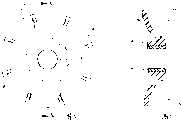
图8为具有三维弯曲的叶片的叶轮的立体图。Figure 8 is a perspective view of an impeller with three-dimensionally curved blades.
具体实施方式Detailed ways
图1示出本发明的叶轮1的结构。抗旋转地在轴2上位置固定的叶轮1用于确保在安装状态下冷却剂、特别是冷却水的循环。叶轮1的结构包括后壁3,该后壁也称为底部并在中心包括轮毂4。轮毂4的孔5用于容纳轴2。此外,后壁3与径向或轴向-径向弯曲形成的导向叶片6一体连接,这些导向叶片在内侧从轮毂4的区域起径向一直延伸到后壁3的外轮廓。FIG. 1 shows the structure of the
在前侧,导向叶片6被模制盘7覆盖,模制盘从导向叶片6的外轮廓起将导向叶片的有限的前侧区域覆盖。模制盘7在内侧一体地设有管状的突缘8。在工作状态下,冷却介质在轴向沿着轴2的方向被输送给叶轮1,并在叶轮1内部换向,其中冷却介质从叶轮1中径向排出。On the front side, the
图2和3示出了叶轮1的其它细节。导向叶片6的造型显示为模制盘7中的局部画出部分。也称为圆环盘的模制盘7在很大程度上延伸经过在轮毂4的外轮廓和后壁3之间确定的距离的一半。模制盘7的突缘8的内直径“di”确定了冷却剂流入到叶轮1中的流入横截面。由后壁3、模制盘7以及插入到轮毂4的孔5中的轴套9a构成的多件式结构的叶轮1一致地由热塑性的塑料(间同立构聚苯乙烯,PS-S-GF 30)制成。由于这种材料的良好的粘接特性,所以叶轮1的所有单个部件都可相互粘接。2 and 3 show further details of the
其中第一接合区域10设置在模制盘7和导向叶片6之间。其中在至少短时间地压紧模制盘7和导向叶片6之前,在模制盘7或导向叶片6上至少在接合区域10中的接触区上有目的地涂覆合适的胶粘剂,直到该胶接硬化。作为替代方案,此外也可以将胶粘剂涂覆在接合区域10中的两个接触区上。另外,轴套9a通过粘接持久地固定在轮毂4中。为此,在轴套9a插入到孔5中之前,轴套9a的外壳面或者轮毂4的孔5被敷设有胶粘剂。优选轴套9a在外侧具有滚花,由此附加地实现形锁合的、抗旋转的固定。In this case, the first joining
图4和5示出后壁3,其与导向叶片6和轮毂4一体连接并且在两个角度描述。作为对根据图3的轴套9a的替代方案,根据图5的轮毂4包括由钢制成的轴套9b。为了实现抗旋转的安装位置,轴套9b通过粘接或压配合抗旋转地定位在轮毂4中。图4示出导向叶片6的造型及其纵向延伸和在后壁3上的分布。根据图5,每个导向叶片6都在倾斜的端侧面上分别设有突出的榫舌或榫11。所有的榫舌11在接合区域10中一起形成配属于导向叶片6的接触区。4 and 5 show the
图6和7示出榫舌11的布置、位置以及构型,这些榫舌与模制盘7上的相应的凹槽12相对应。由此这些凹槽12在接合区域10中形成模制盘7的接触区。6 and 7 show the arrangement, position and configuration of the
根据图8的叶轮14包括导向叶片13,这些导向叶片一致地三维(3D)弯曲。The impeller 14 according to FIG. 8 comprises guide vanes 13 which are uniformly three-dimensionally (3D) curved.
附图标记列表List of reference signs
1 叶轮1 impeller
2 轴2 axis
3 后壁3 rear wall
4 轮毂4 hubs
5 孔5 holes
6 导向叶片6 Guide vanes
7 模制盘7 molded discs
8 突缘8 nosing
9a 轴套9a Shaft sleeve
9b 轴套9b bushing
10 接合区域10 joint area
11 榫舌11 tongue
12 凹槽12 grooves
13 导向叶片13 guide vanes
14 叶轮14 impeller
Claims (11)
Applications Claiming Priority (3)
| Application Number | Priority Date | Filing Date | Title |
|---|---|---|---|
| DE102005031589.5 | 2005-07-06 | ||
| DE200510031589DE102005031589A1 (en) | 2005-07-06 | 2005-07-06 | Wasserpumpenflügelrad |
| PCT/EP2006/005832WO2007003265A1 (en) | 2005-07-06 | 2006-06-17 | Water pump impeller |
Publications (2)
| Publication Number | Publication Date |
|---|---|
| CN101208522Atrue CN101208522A (en) | 2008-06-25 |
| CN101208522B CN101208522B (en) | 2010-06-16 |
Family
ID=36952737
Family Applications (1)
| Application Number | Title | Priority Date | Filing Date |
|---|---|---|---|
| CN2006800232411AExpired - Fee RelatedCN101208522B (en) | 2005-07-06 | 2006-06-17 | Water pump impeller and manufacturing method thereof |
Country Status (6)
| Country | Link |
|---|---|
| US (1) | US20080199319A1 (en) |
| EP (1) | EP1904748B1 (en) |
| JP (1) | JP2008545095A (en) |
| CN (1) | CN101208522B (en) |
| DE (2) | DE102005031589A1 (en) |
| WO (1) | WO2007003265A1 (en) |
Cited By (4)
| Publication number | Priority date | Publication date | Assignee | Title |
|---|---|---|---|---|
| CN103826671A (en)* | 2011-06-02 | 2014-05-28 | 又荣医疗有限公司 | An apparatus relating to hemodialysis, hemodiafiltration, hemofiltration or peritoneal dialysis having function for rise temperature |
| CN106575904A (en)* | 2014-06-05 | 2017-04-19 | 三星电子株式会社 | Motor assembly |
| CN107206543A (en)* | 2015-01-19 | 2017-09-26 | 株式会社荏原制作所 | Ultrasonic welding method and the product obtained using this method |
| CN111120344A (en)* | 2019-12-29 | 2020-05-08 | 昆明研顶技术开发有限公司 | Water immersion type submersible electric pump floating impeller |
Families Citing this family (17)
| Publication number | Priority date | Publication date | Assignee | Title |
|---|---|---|---|---|
| US20080229742A1 (en)* | 2007-03-21 | 2008-09-25 | Philippe Renaud | Extended Leading-Edge Compressor Wheel |
| AT506342B1 (en)* | 2008-01-25 | 2011-03-15 | Bitter Engineering & Systemtechnik Gmbh | WHEEL FOR A PUMP |
| AU2009215853B2 (en)* | 2008-02-22 | 2014-08-14 | Horton, Inc. | Hybrid flow fan apparatus |
| GB2467967B (en)* | 2009-02-24 | 2015-04-22 | Dyson Technology Ltd | Rotor assembly |
| DE102010015202A1 (en) | 2010-04-16 | 2011-12-15 | Schaeffler Technologies Gmbh & Co. Kg | Use of an at least partially radiation-crosslinked thermoplastic material in a motor vehicle |
| WO2012051642A1 (en)* | 2010-09-24 | 2012-04-26 | New Fluid Technology Pty Ltd | Impeller assembly method |
| GB2487921B (en) | 2011-02-08 | 2013-06-12 | Dyson Technology Ltd | Rotor for a turbomachine |
| DE102011078577A1 (en) | 2011-07-04 | 2013-01-10 | Schaeffler Technologies AG & Co. KG | Hydraulic tensioner for traction drive of internal combustion engine used in motor vehicle, has thermoplastic material that is partially cross-linked |
| US9086075B2 (en) | 2011-07-07 | 2015-07-21 | Pentair Water Pool And Spa, Inc. | Impeller assembly and method |
| ES2401866B1 (en)* | 2011-10-13 | 2014-09-08 | Desarrollos Empresariales Valar, S.L. | TURBINE FOR LARGE FLOW PUMPS |
| JP5977693B2 (en)* | 2012-09-26 | 2016-08-24 | 日立オートモティブシステムズ株式会社 | Impeller and water pump |
| DE102013212487A1 (en) | 2013-06-27 | 2014-12-31 | Schaeffler Technologies Gmbh & Co. Kg | Bushing for pump impellers, pump impeller kit and coolant pump |
| CA2966053C (en)* | 2016-05-05 | 2022-10-18 | Tti (Macao Commercial Offshore) Limited | Mixed flow fan |
| US11473589B2 (en) | 2018-05-18 | 2022-10-18 | Franklin Electric Co., Inc. | Impeller assemblies and method of making |
| CN109253108B (en)* | 2018-11-14 | 2025-02-18 | 刘子鸣 | An injection molded submersible pump closed impeller and production method thereof |
| DE102020110150A1 (en) | 2020-04-14 | 2021-10-14 | Daimler Ag | Impeller for a flow compressor and method |
| DE102020123517B4 (en) | 2020-09-09 | 2024-06-06 | Nidec Gpm Gmbh | Impeller for a centrifugal fluid pump and centrifugal fluid pump comprising the impeller and motor vehicle comprising such a centrifugal fluid pump |
Family Cites Families (15)
| Publication number | Priority date | Publication date | Assignee | Title |
|---|---|---|---|---|
| US1953064A (en)* | 1931-12-19 | 1934-04-03 | Parsons C A & Co Ltd | Centrifugal apparatus such as fans, impellers, and the like |
| FI71266C (en)* | 1984-10-23 | 1990-02-27 | Ahlstroem Oy | SAETT ATT BELAEGGA EN PUMPS LOEPHJUL. |
| JPH0648158Y2 (en)* | 1985-06-29 | 1994-12-07 | クリフアーフアーツオイクタイレ・ゲゼルシヤフト・ミツト・ベシユレンクテル・ハフツング・プラス・コムパニー | Water pump impeller |
| FR2703111B1 (en)* | 1993-03-25 | 1995-06-30 | Ozen Sa | ROTOR FOR PUMP COMPRISING TWO WELDED ASSEMBLIES, OBTAINED BY INJECTION MOLDING OF THERMOPLASTIC MATERIALS, AND METHOD FOR MANUFACTURING SUCH A ROTOR. |
| DE19701297A1 (en)* | 1997-01-16 | 1998-07-23 | Wilo Gmbh | Impeller of a centrifugal pump |
| JP2000073992A (en)* | 1998-08-26 | 2000-03-07 | Idemitsu Petrochem Co Ltd | Fan |
| DE19983482B4 (en)* | 1998-09-09 | 2006-09-28 | Asahi Kasei Chemicals Corp. | Use of compatibilized resin compositions for liquid containers of an antifreeze system |
| DE10006983A1 (en)* | 2000-02-16 | 2001-08-23 | Miele & Cie | Pump impeller for a centrifugal pump, in particular for a circulation pump that can be used in dishwashers or washing machines |
| US6413039B1 (en)* | 2000-06-01 | 2002-07-02 | Uis, Inc | Impeller for coolant pumps |
| CN1193171C (en)* | 2000-06-09 | 2005-03-16 | 宜兴市火花特种材料设备厂 | Enclosed integral polyurethane blade wheel and mould for making it |
| US20020144808A1 (en)* | 2001-04-04 | 2002-10-10 | Jones Bart R. | Adhesively bonded radiator assembly |
| JP2004285937A (en)* | 2003-03-24 | 2004-10-14 | Matsushita Electric Ind Co Ltd | Blower fan |
| DE50300812D1 (en)* | 2003-04-24 | 2005-08-25 | Joma Hydromechanic Gmbh | Vane pump |
| DE10354749A1 (en)* | 2003-11-21 | 2005-06-23 | Siemens Ag | Method for producing an impeller for a centrifugal pump |
| JP4565870B2 (en)* | 2004-03-26 | 2010-10-20 | ミネベア株式会社 | Electric pump |
- 2005
- 2005-07-06DEDE200510031589patent/DE102005031589A1/ennot_activeWithdrawn
- 2006
- 2006-06-17DEDE200650008475patent/DE502006008475D1/enactiveActive
- 2006-06-17EPEP20060754428patent/EP1904748B1/ennot_activeNot-in-force
- 2006-06-17WOPCT/EP2006/005832patent/WO2007003265A1/enactiveApplication Filing
- 2006-06-17CNCN2006800232411Apatent/CN101208522B/ennot_activeExpired - Fee Related
- 2006-06-17USUS11/994,804patent/US20080199319A1/ennot_activeAbandoned
- 2006-06-17JPJP2008519818Apatent/JP2008545095A/enactivePending
Cited By (7)
| Publication number | Priority date | Publication date | Assignee | Title |
|---|---|---|---|---|
| CN103826671A (en)* | 2011-06-02 | 2014-05-28 | 又荣医疗有限公司 | An apparatus relating to hemodialysis, hemodiafiltration, hemofiltration or peritoneal dialysis having function for rise temperature |
| CN106575904A (en)* | 2014-06-05 | 2017-04-19 | 三星电子株式会社 | Motor assembly |
| US10749410B2 (en) | 2014-06-05 | 2020-08-18 | Samsung Electronics Co., Ltd. | Motor assembly |
| US10778065B2 (en) | 2014-06-05 | 2020-09-15 | Samsung Electronics Co., Ltd. | Motor assembly |
| CN107206543A (en)* | 2015-01-19 | 2017-09-26 | 株式会社荏原制作所 | Ultrasonic welding method and the product obtained using this method |
| TWI687273B (en)* | 2015-01-19 | 2020-03-11 | 日商荏原製作所股份有限公司 | Diffuser for fluid-operated pump and method of manufacturing the same |
| CN111120344A (en)* | 2019-12-29 | 2020-05-08 | 昆明研顶技术开发有限公司 | Water immersion type submersible electric pump floating impeller |
Also Published As
| Publication number | Publication date |
|---|---|
| US20080199319A1 (en) | 2008-08-21 |
| JP2008545095A (en) | 2008-12-11 |
| DE502006008475D1 (en) | 2011-01-20 |
| CN101208522B (en) | 2010-06-16 |
| WO2007003265A1 (en) | 2007-01-11 |
| EP1904748B1 (en) | 2010-12-08 |
| EP1904748A1 (en) | 2008-04-02 |
| DE102005031589A1 (en) | 2007-01-11 |
Similar Documents
| Publication | Publication Date | Title |
|---|---|---|
| CN101208522B (en) | Water pump impeller and manufacturing method thereof | |
| US6848887B2 (en) | Turbofan and mold thereof | |
| US6755615B2 (en) | High efficiency one-piece centrifugal blower | |
| US8028999B2 (en) | Axle boot | |
| US8469671B2 (en) | Impeller | |
| US20110033320A1 (en) | Pump rotor for a canned motor pump | |
| US6854960B2 (en) | Segmented composite impeller/propeller arrangement and manufacturing method | |
| US4820131A (en) | Venturi nozzle assembly construction in a shallow well pump casing | |
| US20080118357A1 (en) | Turbofan and manufacturing method thereof | |
| CN101410663B (en) | Mosaic connecting accessory for pipeline | |
| EP2286096A1 (en) | An insert kit and installation method | |
| JP2002500743A (en) | Improved wheel with blade | |
| CN102138005A (en) | Rotor for a radial machine | |
| DE202005021324U1 (en) | Wasserpumpenflügelrad | |
| CN113581094B (en) | Automobile exterior trim part and manufacturing method thereof | |
| US6506024B1 (en) | Inducer wheel and method of forming the same | |
| CN117813188A (en) | Connection arrangement device and method for fluid lines | |
| WO2015190219A1 (en) | Negative pressure pump and manufacturing method thereof | |
| US6416287B1 (en) | Impeller | |
| CN219013632U (en) | Pipe joint with sealing groove, inverter comprising pipe joint and electric drive system | |
| EP1797791A2 (en) | Hub flange for cast hub brush | |
| CN119617957A (en) | Thermal management device and method of making the same | |
| CN117052655B (en) | Roller pump | |
| CN219345073U (en) | Pump body structure and water pump | |
| JPH10159787A (en) | Centraifugal multi-vane fan |
Legal Events
| Date | Code | Title | Description |
|---|---|---|---|
| C06 | Publication | ||
| PB01 | Publication | ||
| C10 | Entry into substantive examination | ||
| SE01 | Entry into force of request for substantive examination | ||
| C14 | Grant of patent or utility model | ||
| GR01 | Patent grant | ||
| C17 | Cessation of patent right | ||
| CF01 | Termination of patent right due to non-payment of annual fee | Granted publication date:20100616 Termination date:20120617 |