CN101208497B - Turbine thermal shield and guide vane for a gas turbine - Google Patents
Turbine thermal shield and guide vane for a gas turbineDownload PDFInfo
- Publication number
- CN101208497B CN101208497BCN200680022910.3ACN200680022910ACN101208497BCN 101208497 BCN101208497 BCN 101208497BCN 200680022910 ACN200680022910 ACN 200680022910ACN 101208497 BCN101208497 BCN 101208497B
- Authority
- CN
- China
- Prior art keywords
- thermal insulation
- hot gas
- platform
- guide vane
- blade
- Prior art date
- Legal status (The legal status is an assumption and is not a legal conclusion. Google has not performed a legal analysis and makes no representation as to the accuracy of the status listed.)
- Expired - Fee Related
Links
- 238000009413insulationMethods0.000claimsabstractdescription77
- 239000012530fluidSubstances0.000claimsabstractdescription42
- 238000011144upstream manufacturingMethods0.000claimsabstractdescription6
- 238000009434installationMethods0.000claimsdescription15
- 239000000463materialSubstances0.000claimsdescription7
- 239000007789gasSubstances0.000description92
- 238000001816coolingMethods0.000description49
- 238000002485combustion reactionMethods0.000description15
- 238000000576coating methodMethods0.000description6
- 239000002184metalSubstances0.000description6
- 239000011248coating agentSubstances0.000description5
- 238000005260corrosionMethods0.000description5
- 230000003647oxidationEffects0.000description5
- 238000007254oxidation reactionMethods0.000description5
- 230000007704transitionEffects0.000description5
- 230000007797corrosionEffects0.000description4
- 238000007689inspectionMethods0.000description4
- 230000002093peripheral effectEffects0.000description4
- 230000000903blocking effectEffects0.000description3
- 238000009826distributionMethods0.000description2
- 238000005457optimizationMethods0.000description2
- 238000013021overheatingMethods0.000description2
- 230000006978adaptationEffects0.000description1
- 230000003064anti-oxidating effectEffects0.000description1
- 230000015572biosynthetic processEffects0.000description1
- 238000010276constructionMethods0.000description1
- 230000002349favourable effectEffects0.000description1
- 238000010438heat treatmentMethods0.000description1
- 230000004048modificationEffects0.000description1
- 238000012986modificationMethods0.000description1
- 230000000149penetrating effectEffects0.000description1
- 230000035515penetrationEffects0.000description1
- 230000008439repair processEffects0.000description1
- 238000003466weldingMethods0.000description1
Images

Classifications
- F—MECHANICAL ENGINEERING; LIGHTING; HEATING; WEAPONS; BLASTING
- F01—MACHINES OR ENGINES IN GENERAL; ENGINE PLANTS IN GENERAL; STEAM ENGINES
- F01D—NON-POSITIVE DISPLACEMENT MACHINES OR ENGINES, e.g. STEAM TURBINES
- F01D5/00—Blades; Blade-carrying members; Heating, heat-insulating, cooling or antivibration means on the blades or the members
- F01D5/12—Blades
- F01D5/14—Form or construction
- F01D5/141—Shape, i.e. outer, aerodynamic form
- F01D5/142—Shape, i.e. outer, aerodynamic form of the blades of successive rotor or stator blade-rows
- F01D5/143—Contour of the outer or inner working fluid flow path wall, i.e. shroud or hub contour
- F—MECHANICAL ENGINEERING; LIGHTING; HEATING; WEAPONS; BLASTING
- F01—MACHINES OR ENGINES IN GENERAL; ENGINE PLANTS IN GENERAL; STEAM ENGINES
- F01D—NON-POSITIVE DISPLACEMENT MACHINES OR ENGINES, e.g. STEAM TURBINES
- F01D11/00—Preventing or minimising internal leakage of working-fluid, e.g. between stages
- F01D11/005—Sealing means between non relatively rotating elements
- F—MECHANICAL ENGINEERING; LIGHTING; HEATING; WEAPONS; BLASTING
- F01—MACHINES OR ENGINES IN GENERAL; ENGINE PLANTS IN GENERAL; STEAM ENGINES
- F01D—NON-POSITIVE DISPLACEMENT MACHINES OR ENGINES, e.g. STEAM TURBINES
- F01D9/00—Stators
- F01D9/02—Nozzles; Nozzle boxes; Stator blades; Guide conduits, e.g. individual nozzles
- F01D9/023—Transition ducts between combustor cans and first stage of the turbine in gas-turbine engines; their cooling or sealings
- F—MECHANICAL ENGINEERING; LIGHTING; HEATING; WEAPONS; BLASTING
- F05—INDEXING SCHEMES RELATING TO ENGINES OR PUMPS IN VARIOUS SUBCLASSES OF CLASSES F01-F04
- F05D—INDEXING SCHEME FOR ASPECTS RELATING TO NON-POSITIVE-DISPLACEMENT MACHINES OR ENGINES, GAS-TURBINES OR JET-PROPULSION PLANTS
- F05D2240/00—Components
- F05D2240/80—Platforms for stationary or moving blades
- F—MECHANICAL ENGINEERING; LIGHTING; HEATING; WEAPONS; BLASTING
- F05—INDEXING SCHEMES RELATING TO ENGINES OR PUMPS IN VARIOUS SUBCLASSES OF CLASSES F01-F04
- F05D—INDEXING SCHEME FOR ASPECTS RELATING TO NON-POSITIVE-DISPLACEMENT MACHINES OR ENGINES, GAS-TURBINES OR JET-PROPULSION PLANTS
- F05D2260/00—Function
- F05D2260/20—Heat transfer, e.g. cooling
- F05D2260/201—Heat transfer, e.g. cooling by impingement of a fluid
- F—MECHANICAL ENGINEERING; LIGHTING; HEATING; WEAPONS; BLASTING
- F05—INDEXING SCHEMES RELATING TO ENGINES OR PUMPS IN VARIOUS SUBCLASSES OF CLASSES F01-F04
- F05D—INDEXING SCHEME FOR ASPECTS RELATING TO NON-POSITIVE-DISPLACEMENT MACHINES OR ENGINES, GAS-TURBINES OR JET-PROPULSION PLANTS
- F05D2260/00—Function
- F05D2260/20—Heat transfer, e.g. cooling
- F05D2260/202—Heat transfer, e.g. cooling by film cooling
- F—MECHANICAL ENGINEERING; LIGHTING; HEATING; WEAPONS; BLASTING
- F05—INDEXING SCHEMES RELATING TO ENGINES OR PUMPS IN VARIOUS SUBCLASSES OF CLASSES F01-F04
- F05D—INDEXING SCHEME FOR ASPECTS RELATING TO NON-POSITIVE-DISPLACEMENT MACHINES OR ENGINES, GAS-TURBINES OR JET-PROPULSION PLANTS
- F05D2300/00—Materials; Properties thereof
- F05D2300/50—Intrinsic material properties or characteristics
- F05D2300/502—Thermal properties
- F05D2300/5021—Expansivity
Landscapes
- Engineering & Computer Science (AREA)
- Mechanical Engineering (AREA)
- General Engineering & Computer Science (AREA)
- Physics & Mathematics (AREA)
- Fluid Mechanics (AREA)
- Turbine Rotor Nozzle Sealing (AREA)
Abstract
Translated fromChinese
Description
Translated fromChinese本发明涉及一种流体壳体,其具有围成流动路径的壁结构,具有至少一个集成在壁结构上用于在流动路径中导流的导向叶片以及设置在壁结构上的隔热板。本发明尤其涉及一种用于燃气轮机装置的流体壳体。此外,本发明还涉及一种用于流体壳体的导向叶片和隔热元件。The invention relates to a fluid housing having a wall structure enclosing a flow path, at least one guide vane integrated in the wall structure for guiding the flow in the flow path, and a heat shield arranged on the wall structure. In particular, the invention relates to a fluid casing for a gas turbine installation. Furthermore, the invention relates to a guide vane and a thermal insulation element for a fluid housing.
用于热燃气流通的流体壳体通常包括带有支承结构的壁结构和朝向壳体内部位于支承结构之前的隔热板。隔热板应防止支承结构过度受热以及腐蚀和/或氧化。在这种流体壳体内也常常设置用于导流的导向叶片。例如可以在燃气轮机装置中将燃烧室和在流动方向上连接在下游的透平部分看作流体壳体。在此,在从燃烧室到透平部分的过渡区域设置用于引导热燃气流的导向叶片。Fluid housings for the circulation of hot gas generally comprise a wall structure with a support structure and a thermal insulation panel located in front of the support structure towards the interior of the housing. Thermal shields shall protect the supporting structure from overheating as well as from corrosion and/or oxidation. Guide vanes for guiding the flow are also frequently provided in such fluid housings. For example, in a gas turbine system, the combustion chamber and the downstream turbine part in the direction of flow can be considered as a fluid casing. In this case, guide vanes for guiding the hot gas flow are arranged in the transition region from the combustion chamber to the turbine part.
为了允许暴露在热燃气中的流体壳体元件热膨胀,这些元件之间常常留有间隙地相邻。为了防止热燃气进入间隙,可通过这些间隙将冷却空气送入流动路径内。在此,流出的冷却空气的压力应高于朝向冷却空气间隙流动的热燃气的压力。To allow thermal expansion of fluid housing elements exposed to hot gases, these elements are often adjacent with a gap between them. To prevent hot gases from entering the gaps, cooling air can be fed into the flow path through these gaps. In this case, the pressure of the cooling air flowing out should be higher than the pressure of the hot gas flowing towards the cooling air gap.
这种冷却空气间隙例如位于燃气轮机装置中燃气轮机装置的燃烧室及其透平部分之间的过渡区域,更准确地说是位于设置在燃烧室和透平部分之间区域的燃烧室隔热元件和在流动方向上与隔热元件相邻的透平部分的导向叶片之间。Such a cooling air gap is located, for example, in the transition region between the combustion chamber of the gas turbine installation and its turbine part in a gas turbine installation, more precisely in the combustion chamber insulation element and the Between the guide vanes of the turbine section adjacent to the thermal insulation element in the direction of flow.
当在这些冷却空气间隙的区域内形成阻塞点时,将会造成热燃气在这些阻塞点的区域内逆通常的流动方向流动。此外,由于阻塞产生阻塞压力在某些情况下会高于从隔热元件和导向叶片之间的冷却空气间隙流出的冷却空气的压力。因为冷却空气优先从热燃气压力低的区域中的间隙流出,所以,当某个位置发生阻塞时就会降低该处的冷却。因此会导致提高热负荷。此外,也可能发生的是,热燃气在阻塞点的压力是如此之大,以至于热燃气能克服冷却空气流进入间隙,从而导致邻近壁结构的腐蚀增大。其结果便是鉴于燃气轮机装置的检测或检查更经常地更换部件和/或焊接修理。If choke points are formed in the region of these cooling air gaps, this will cause the hot gas to flow counter to the usual direction of flow in the region of these choke points. Furthermore, the blocking pressure due to the blocking can in some cases be higher than the pressure of the cooling air flowing out of the cooling air gap between the heat insulating element and the guide vanes. Because cooling air preferentially flows out of gaps in areas of low hot gas pressure, a blockage at a location reduces cooling there. This results in an increased thermal load. Furthermore, it can also happen that the pressure of the hot gas at the choke point is so great that the hot gas can overcome the flow of cooling air and enter the gap, leading to increased corrosion of adjacent wall structures. The result is more frequent replacement of components and/or welding repairs for inspection or inspection of gas turbine installations.
为了避免上述问题点,通常提高冷却空气的供给。然而,这种方法会导致燃气轮机装置效率降低并导致有害排出物的增加。In order to avoid the above problems, the supply of cooling air is generally increased. However, this approach results in reduced gas turbine plant efficiency and an increase in harmful emissions.
本发明所要解决的技术问题是提供一种用于热燃气流通的流体壳体,尤其是用于燃气轮机装置的流体壳体,在按本发明的流体壳体中可以在不增大冷却空气供给时相对现有技术降低流体壳体在隔热元件和与之相邻的导向叶片之间区域的热负荷。本发明所要解决的另一技术问题是提供一种可有利地用于流体壳体构造的壳体部件。The technical problem to be solved by the present invention is to provide a fluid casing for hot gas circulation, especially for a gas turbine device, in which the fluid casing according to the present invention can be used without increasing the supply of cooling air The thermal loading of the fluid housing in the region between the thermal insulation element and the guide vanes adjacent thereto is reduced compared to the prior art. Another technical problem addressed by the invention is to provide a housing part which can be advantageously used in the construction of fluid housings.
第一个技术问题通过一种用于热燃气流动的流体壳体解决,其具有围成一流动路径的壁结构,至少一个集成在壁结构上用于在流动路径中导流的导向叶片,该导向叶片具有带有前缘的叶片,其中,所述导向叶片具有带有平台表面的叶片平台,所述叶片平台形成流动路径的一壁段并具有一在朝所述隔热元件方向前置于所述前缘的表面区域,所述表面区域形成流动路径的一壁段,以及一个设置在壁结构的支承结构上的隔热板,该隔热板带有与叶片平台之间构成间隙并且直接前置在所述叶片平台上游的隔热元件,所述隔热元件具有一背向于支承结构的、形成流动路径一壁段的热燃气侧的隔热表面,其中,所述导向叶片和所述隔热元件这样地彼此相对设置,即,所述热燃气侧的隔热表面设置成至少与所述平台表面平齐,所述隔热元件部分搭接在所述叶片平台上,并且所述叶片平台的棱边具有一横向于流动方向延伸的凹槽,并且所述隔热元件在其朝向叶片平台的一侧具有一与所述热燃气表面齐平并突入所述叶片平台的凹槽的桥形接片;第二个技术问题通过一种用于燃气轮机装置的的导向叶片解决,该导向叶片具有一前缘和在流入方向上前置于所述前缘的表面区域,所述在流入方向上前置于所述前缘的表面区域在流入侧具有带有横向于流入方向延伸的凹槽的棱边段;或通过一种用于燃气轮机装置的隔热元件解决,其具有一面向热燃气的热燃气表面和一桥形接片,所述桥形接片设置在所述隔热元件于流出方向一侧的棱边上并且具有与所述热燃气表面齐平的桥接片表面,所述桥形接片具有至少一个槽和/或所述桥形接片是分段的。The first technical problem is solved by a fluid housing for the flow of hot gas, which has a wall structure enclosing a flow path, at least one guide vane integrated on the wall structure for guiding the flow in the flow path, the The guide vane has a vane with a leading edge, wherein the guide vane has a vane platform with a platform surface, which forms a wall section of the flow path and has a The surface area of the leading edge, which forms a wall section of the flow path, and a heat shield arranged on the support structure of the wall structure, the heat shield has a gap between the blade platform and directly An insulating element upstream of the blade platform, which has an insulating surface facing away from the support structure on the hot gas side forming a wall section of the flow path, wherein the guide vanes and the The thermal insulation elements are arranged opposite to each other in such a way that the thermal insulation surface of the hot gas side is arranged at least flush with the platform surface, the thermal insulation elements partially overlap the blade platform, and the The edge of the blade platform has a groove extending transversely to the direction of flow, and the insulating element has a groove on its side facing the blade platform which is flush with the hot gas surface and protrudes into the groove of the blade platform. Bridge web; the second technical problem is solved by a guide vane for a gas turbine installation, which has a leading edge and a surface area which is situated in front of the leading edge in the direction of inflow. The surface area of the front edge in the direction has an edge section on the inflow side with a groove extending transversely to the inflow direction; The hot gas surface of the gas and a bridge-shaped web, the bridge-shaped web is arranged on the edge of the thermal insulation element on one side of the outflow direction and has a bridge surface flush with the hot gas surface, so The webs have at least one groove and/or the webs are segmented.
一种用于热燃气流通的流体壳体,尤其是作为可用于燃气轮机装置的流体壳体设计的流体壳体,其包括围成一流动路径的壁结构,至少一个集成在壁结构上用于在流动路径中导流的导向叶片以及一布置在壁结构的支承结构上的隔热板。A fluid housing for the circulation of hot gas, in particular designed as a fluid housing for gas turbine installations, comprising a wall structure enclosing a flow path, at least one of which is integrated on the wall structure for the Guide vanes guiding the flow in the flow path and a heat shield arranged on the support structure of the wall structure.
导向叶片配设有也称作叶根或叶片顶部的叶片平台。叶片平台具有构成流动路径一壁段的平台表面。为了在流动的热燃气前保护叶片以及叶片平台,叶片及叶片平台可具有绝热的以及抗腐蚀和/或抗氧化的涂层。The guide blade is provided with a blade platform, also called blade root or blade tip. The blade platform has a platform surface forming a wall segment of the flow path. In order to protect the blades and the blade platforms in front of the flowing hot gas, the blades and the blade platforms can have a heat-insulating and corrosion- and/or oxidation-resistant coating.
隔热板包括一与叶片平台之间形成间隙并且直接前置在所述叶片平台上游的隔热元件,该元件具有背向壁结构的热燃气侧的隔热表面,所述隔热表面构成流动路径的一壁段。隔热元件通常由金属制成并且可具有绝热的以及抗腐蚀和/或抗氧化的涂层。The insulating plate comprises an insulating element forming a gap with the vane platform and directly upstream of said vane platform, which element has an insulating surface facing away from the hot gas side of the wall structure, said insulating surface constituting a flow A wall segment of the path. The thermal insulation element is usually made of metal and can have a thermally insulating and corrosion- and/or oxidation-resistant coating.
在按本发明的流体壳体中,导向叶片和隔热元件这样地相对彼此设置,即,热燃气侧的隔热表面相对于流动路径较平台表面更靠里或者热燃气侧的隔热板表面至少与平台表面齐平。通过这种方法,热燃气侧的隔热表面(接下来称作热燃气表面)和平台表面为热燃气形成一个没有阻塞点的导引面,所述导引面在隔热板表面和平台表面齐平对齐时没有梯度。In the fluid housing according to the invention, the guide vanes and the thermal insulation elements are arranged relative to one another in such a way that the thermal insulation surface on the hot gas side is located further inwards relative to the flow path than the platform surface or the thermal insulation panel surface on the hot gas side At least flush with the platform surface. In this way, the insulating surface on the hot gas side (hereinafter referred to as the hot gas surface) and the platform surface form a guide surface for the hot gas without choking points, which guide surface is located between the insulation plate surface and the platform surface There is no gradient when aligned flush.
由于所述对齐可以有效地避免导向叶片前的阻塞点,因此,在这些区域不会产生热燃气压力的升高。因此也允许在不提高冷却空气用量的情况下避免间隙区域的过热及其腐蚀和/或氧化的增加。总的来说,由此可以延长零部件的寿命并且降低检测或检查的费用。Since said alignment effectively avoids choke points in front of the guide vanes, no rise in hot gas pressure occurs in these areas. This also makes it possible to avoid overheating of the interstitial region and its increase in corrosion and/or oxidation without increasing the cooling air consumption. Overall, the service life of the components can thus be extended and the outlay for inspection or inspection reduced.
在按本发明的流体壳体的一个有益的设计中,导向叶片具有一个前缘并且叶片平台具有一个在朝隔热元件方向置于前缘之前的表面区域。所述前置的表面区域形成流动路径的一壁段。所述表面区域尤其可以这样设计,即,其与隔热元件的热燃气表面平齐的对齐。此外,当该表面区域具有朝向隔热元件的小曲率半径的棱边时,前置表面部分的导引热燃气通过的表面可以尤其靠近冷却空气孔并从而尤其靠近隔热元件的导引热燃气通过的表面,因此不会产生梯度。In an advantageous embodiment of the fluid housing according to the invention, the guide vane has a leading edge and the vane platform has a surface area which is situated in front of the leading edge in the direction of the thermal insulation element. The upstream surface area forms a wall section of the flow path. In particular, the surface area can be designed in such a way that it is aligned flush with the hot gas surface of the insulating element. Furthermore, the hot gas-conducting surface of the front surface part can be located in particular close to the cooling air openings and thus in particular to the hot gas-conducting surface of the thermal insulation element if the surface region has an edge with a small radius of curvature facing the thermal insulation element. through the surface, so no gradients are created.
在流体壳体的一个尤其有利的设计中是这样设计的,即,在加载流动的热燃气时导向叶片的纵向膨胀不被阻碍。此外,隔热元件的材料参数(Materialparameter)是这样选择的,即,隔热元件在加载流动的热燃气时,其热燃气表面在叶片纵向膨胀时跟随叶片平台的表面变形。In a particularly advantageous embodiment of the fluid housing, it is provided that the longitudinal expansion of the guide vanes is not hindered when the flowing hot gas is applied. In addition, the material parameter of the thermal insulation element is selected such that when the thermal insulation element is loaded with flowing hot gas, its hot gas surface deforms following the surface of the blade platform when the blade expands longitudinally.
典型地,与导向叶片相邻的隔热元件在中间区域与流体壳体的支承结构拧紧。通过适当的选择材料参数可以实现隔热元件的各边缘相对于拧紧的中间区域规定地弯曲。隔热元件尤其可以这样固定在支承结构上,即,在隔热元件朝向叶片平台的部分和至少在冷却状态,也就是说在没有加载热燃气的状态时的隔热元件的支承结构之间留有间隙。当热燃气流过流体壳体时,导向叶片在纵向膨胀,因此叶片平台的表面和隔热元件的表面在没有其它措施的情况下不再平齐。然而,通过适当的选择隔热元件的材料参数可以实现隔热元件在加载热燃气时的弯曲这样进行,即,隔热元件朝向导向叶片的部分和支承结构之间的间隙缩小或完全封闭。换句话说,在加载热燃气时,热燃气表面朝向叶片的部分向支承结构运动,并且从而在导向叶片纵向膨胀时跟随叶片平台的表面。Typically, the thermal insulation element adjacent to the guide vanes is screwed to the support structure of the fluid housing in the central region. A defined curvature of the edges of the thermal insulation element relative to the screwed-on central region can be achieved by suitable selection of the material parameters. In particular, the thermal insulation element can be fixed on the support structure in such a way that there is a gap between the part of the thermal insulation element facing the blade platform and the support structure of the thermal insulation element at least in the cooled state, that is to say in the state in which no hot gas is loaded. There are gaps. When the hot gas flows through the fluid casing, the guide vanes expand in the longitudinal direction, so that the surfaces of the vane platform and the insulating element are no longer flush without further measures. However, by suitable selection of the material parameters of the thermal insulation element it is possible to bend the thermal insulation element when hot gas is applied such that the gap between the part of the thermal insulation element facing the guide vanes and the support structure is reduced or completely closed. In other words, when hot gas is loaded, the hot gas surface moves towards the part of the blade towards the support structure and thus follows the surface of the blade platform as the guide blade expands longitudinally.
在按本发明的另一有利的设计中,隔热元件具有一个朝向叶片平台的、由热燃气表面朝支承结构方向弯曲的周边,在该周边上设置有冷却空气孔。所述冷却空气孔可以用于有针对性地调节流出的冷却空气量。冷却空气流的优化可以通过冷却空气孔不同的分布实现。各冷却空气孔尤其可以布置在热燃气表面附近。各冷却空气孔导致尤其有利的冷却空气流并且在某些情况下甚至可用于在叶片平台表面的区域产生冷却空气薄膜(Kühlluftfilm)。In a further advantageous embodiment according to the invention, the thermal insulation element has a periphery facing the blade platform which is bent from the hot gas surface in the direction of the support structure, on which periphery the cooling air holes are arranged. The cooling air openings can be used for a targeted regulation of the quantity of cooling air flowing out. Optimization of the cooling air flow can be achieved by different distributions of the cooling air holes. In particular, the cooling air holes can be arranged in the vicinity of the hot gas surface. The cooling air holes lead to a particularly favorable cooling air flow and can even be used in certain cases to generate a cooling air film in the region of the blade platform surface.
当隔热元件部分搭接在叶片平台上时尤其有利。通过这种方法可以避免热燃气进入叶片平台和隔热元件之间的间隙并从而特别有效地防止热燃气侵入间隙区域。此外,可以减少为阻止热燃气进入间隙所需要的冷却空气用量。It is particularly advantageous when the thermal insulation element partially overlaps the blade platform. In this way, hot gases can be prevented from penetrating into the gap between the blade platform and the thermal insulation element and thus the penetration of hot gases into the gap region can be prevented particularly effectively. In addition, the amount of cooling air required to prevent hot gases from entering the gap can be reduced.
搭接例如可由此实现,即,叶片平台的棱边具有一横向于流动方向延伸的凹槽并且隔热元件在其朝向叶片平台的侧面具有一与其热燃气表面齐平并且突入叶片平台的凹槽的桥形接片。在这种情况下,桥形接片可以这样紧密地贴靠在凹槽中,即,在桥形接片和凹槽底部之间的冷却空气间隙几乎完全封闭。当桥形接片具有一个槽,优选甚至多个槽时是尤其有利的。这些槽在间隙封闭时也使冷却空气能够流出。可选地,冷却空气的流出也可以由此保证,即,桥形接片分段地设计。The overlapping can be achieved, for example, in that the edge of the blade platform has a groove extending transversely to the direction of flow and the heat insulating element has a groove on its side facing the blade platform which is flush with its hot gas surface and protrudes into the blade platform. bridge piece. In this case, the webs can rest so tightly in the recesses that the cooling air gap between the webs and the bottom of the recess is almost completely closed. It is particularly advantageous if the bridge has one groove, preferably even a plurality of grooves. These slots also allow cooling air to escape when the gap is closed. Optionally, the outflow of cooling air can also be ensured by the web being designed in sections.
所述流体壳体可以特别有利地应用在燃气轮机装置中。The fluid housing can be used particularly advantageously in gas turbine installations.
一种按本发明的尤其可作为用于燃气轮机装置导向叶片设计的导向叶片,具有一前缘和一在流入方向上(也就是说从该方向进行流入)位于前缘之前的表面区域。表面区域在流入侧可具有一段小曲率半径的棱边。此外,在该段棱边上可存在一横向于流入方向延伸的凹槽。这种类型的导向叶片可以用于构建按本发明的流体壳体。A guide vane according to the invention, which can be designed in particular as a guide vane for gas turbine installations, has a leading edge and a surface region located in front of the leading edge in the direction of inflow (ie from which the inflow takes place). On the inflow side, the surface region can have an edge with a small radius of curvature. Furthermore, there can be a groove extending transversely to the inflow direction on the edge of this segment. Guide vanes of this type can be used to construct the fluid housing according to the invention.
一种按本发明的尤其可设计用于燃气轮机装置的隔热元件,具有一面向热燃气的热燃气表面和一桥形接片。桥形接片在位于流出方向(也就是与流入方向相反的方向)的棱边上具有一与热气表面平齐的桥形接片表面。所述桥形接片表面尤其可具有一个或多个槽或分段地设计。这种类型的隔热元件可以用于构建按本发明的流体壳体。A thermal insulation element according to the invention, which can be designed in particular for gas turbine installations, has a hot gas surface facing the hot gas and a web. On the edge lying in the outflow direction (ie opposite to the inflow direction), the bridge has a bridge surface which is flush with the surface of the hot gas. In particular, the web surface can have one or more grooves or be designed in sections. Thermal insulation elements of this type can be used to construct fluid housings according to the invention.
在隔热元件一非常有利的设计中,其材料参数是这样选择的,即,隔热元件在加载热燃气时进行规定的、与其在热燃气路径中安装位置处的几何结构情况相协调的变形。这种类型的隔热元件可使其热燃气表面这样地跟随例如一个在加载热燃气时纵向膨胀的导向叶片,即,热燃气表面在叶片纵向膨胀时继续几乎完全与叶片平台的一个表面平齐地对齐。In a very advantageous configuration of the thermal insulation element, its material parameters are selected such that the thermal insulation element undergoes a defined deformation when loaded with hot gas that is compatible with the geometrical conditions at its installation location in the hot gas path . This type of insulating element makes it possible for the hot gas surface to follow e.g. a guide vane which expands longitudinally when loaded with hot gas in such a way that the hot gas surface continues almost completely flush with one surface of the blade platform during the longitudinal expansion of the blade ground alignment.
当在流出侧的、从热燃气表面弯折的周边上设置冷却空气孔时,可通过隔热元件在朝例如一个相邻的导向叶片方向进行规定的冷却空气供给。当冷却空气孔设置在热燃气表面附近是尤其有利的,因为必要时可以通过一相邻的元件的表面,例如通过一个相邻的导向叶片的叶片平台的表面形成冷却空气薄膜。A defined supply of cooling air in the direction of, for example, an adjacent guide vane can take place via the heat insulating element if cooling air holes are provided on the outflow-side periphery bent away from the hot gas surface. It is especially advantageous if the cooling air holes are arranged in the vicinity of the hot gas surface, since a cooling air film can possibly be formed by the surface of an adjacent element, for example by the surface of the blade platform of an adjacent guide vane.
接下来借助附图说明实施例,得出本发明其它的特征,特性和优点。Further features, properties and advantages of the invention emerge from the following description of an exemplary embodiment with the aid of the figures.
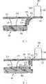
图1表示现有技术中的流体壳体的部分剖切图。Figure 1 shows a partial cutaway view of a prior art fluid housing.
图2表示按本发明流体壳体的第一实施例。FIG. 2 shows a first embodiment of a fluid housing according to the invention.
图3表示按本发明流体壳体的第二实施例。FIG. 3 shows a second embodiment of a fluid housing according to the invention.
图4表示按本发明流体壳体的第三实施例。FIG. 4 shows a third embodiment of a fluid housing according to the invention.
图5表示按本发明流体壳体的第四实施例。FIG. 5 shows a fourth embodiment of a fluid housing according to the invention.
图6表示按本发明隔热元件的第一实施例。Figure 6 shows a first embodiment of a heat insulating element according to the invention.
图7表示按本发明隔热元件的第二实施例。FIG. 7 shows a second embodiment of a heat insulating element according to the invention.
图8表示图6所示隔热元件的一种可选的变形。FIG. 8 shows an alternative variant of the insulating element shown in FIG. 6 .
为了明确本发明相对现有技术的优点,接下来首先借助附图1说明按现有技术的流体壳体。In order to clarify the advantages of the present invention over the prior art, a fluid housing according to the prior art will firstly be described below with reference to FIG. 1 .
图1示出了燃气轮机装置的局部剖视图,其在剖开的侧视图中示出了燃烧室1的一段以及第一透平导向叶片3。该透平导向叶片3包括一个叶片5和两个叶片平台,也就是叶根7和叶片顶部9。燃气轮机装置的燃烧室1和透平部分的壁共同形成用于热的燃烧废气的流体壳体。FIG. 1 shows a partial sectional view of a gas turbine arrangement, showing a section of a combustion chamber 1 and a first turbine guide vane 3 in a cut-away side view. The turbine guide vane 3 comprises a blade 5 and two blade platforms, ie a
在燃烧室1上示出了支承结构2以及固定在其上面的金属隔热元件13。隔热元件13和叶片平台(Schaufelplattform)7,9都具有面对流动热燃气的热燃气表面8,10,14。所述热燃气表面配设有绝热的涂层以及设置于绝热涂层之下的防腐蚀和防氧化涂层。On the combustion chamber 1 is shown a support structure 2 with a metal
在隔热元件13和叶片平台7,9之间存在冷却空气间隙15,为了阻止热燃气进入间隙15,通过所述冷却空气间隙将空气送入流动壳体的内部。所述间隙用于允许隔热元件13之间的因受热导致的相对运动。Between the
如图1所示,在间隙15的区域内,在隔热元件13和叶片平台7,9两者的导引热燃气通过的表面之间存在梯度。在该梯度附近可造成流动热燃气的阻塞,有时甚至能使热燃气的流动方向局部倒转。因此,梯度造成了阻塞点以及与阻塞点相关的前述问题。As shown in FIG. 1 , in the region of the
图2表示按本发明的流体壳体的第一实施例。流体壳体是燃气轮机装置的一部分并且一方面由燃烧室的壁,另一方面由燃气轮机装置的透平部分形成。与图1相同,图2示出了流动壳体的局部剖切图,其中示出了燃烧室101和透平部分的第一导向叶片103之间的过渡。导向叶片103包括叶片105以及两个叶片平台,也就是叶根107和叶片顶部109。与按现有技术的叶片平台不同的是,导向叶片103的叶片平台107,109具有部分111,112,所述部分在流动方向上位于叶片105的前缘之前。所述部分111,112的表面108,110形成叶片平台107,109热燃气通过的表面,所述表面很大程度地平行于热燃气的流动方向R在流动路径上延伸。叶片平台107,109在前缘具有较图1所示叶片平台曲率半径更小的倒角边棱119,121。在所述边棱形成叶片平台107,109的基本上直角的弯折。FIG. 2 shows a first embodiment of a fluid housing according to the invention. The fluid housing is part of the gas turbine arrangement and is formed on the one hand by the walls of the combustion chamber and on the other hand by the turbine part of the gas turbine arrangement. Like FIG. 1 , FIG. 2 shows a partial cutaway view of the flow housing, showing the transition between the
燃气轮机燃烧室101的金属隔热元件113和透平导向叶片105的叶片平台107,109是这样彼此相对布置的,即,隔热元件113的热燃气表面114与平行于流动方向延伸的叶片平台107,109的热燃气表面108,110平齐。通过这种方式,在燃烧室101和透平导向叶片103之间的过渡区域就不存在梯度,因此可以避免阻塞点。存在于隔热元件113和叶片平台107,109之间的间隙为防止热燃气进入所需冷却空气用量可相对于现有技术更小。The metal
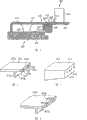
图3示出了按本发明的流体壳体的第二实施例。除支承结构202之外,从图中还可看到燃气轮机装置的透平导向叶片203以及与透平导向叶片203直接相邻的燃烧室201的隔热元件213。透平导向叶片203的叶根207和叶片205具有与图1所示透平导向叶片3相同的形状。然而,金属隔热元件213的热燃气表面214较在图1所示的隔热元件13中离支承结构202更远。此外,隔热元件213具有搭接区域216,所述隔热元件通过所述搭接区域与叶根207部分搭接。因此,搭接区域216的形状如此地与叶根的形状相适应,以便实现从隔热元件213的热燃气表面214至叶根207的热燃气表面208基本上连续的、平齐的过渡。FIG. 3 shows a second exemplary embodiment of a fluid housing according to the invention. In addition to the
搭接区域216具有面对叶根207的周边部段217。该周边部段朝支承结构202的方向延伸并且与叶根207的轮廓相适应。在周边部段207上存在冷却空气孔218,通过所述孔,冷却空气可进入隔热元件213和叶根207之间的间隙215。The overlapping
图4示出了按本发明的隔热元件的第三实施例。由图可知,透平导向叶片303带有叶片305和叶根307以及燃烧室的支承结构302以及固定在其上面的金属隔热元件313。隔热元件313与图2所示的隔热元件113的区别在于,所述隔热元件313在流出侧具有一几乎直角地朝支承结构302方向弯折的周边317以及设置在其中的冷却空气孔318。图7部分地示出了该隔热元件的透视图。FIG. 4 shows a third exemplary embodiment of a thermal insulation element according to the invention. It can be seen from the figure that the
在弯折的周边317和支承结构302之间保留有间隙321,所述间隙允许周边部段317朝支承结构302的方向移动。此外,支承结构302这样设计,即,它不阻碍导向叶片305加载热燃气时的纵向膨胀。由于这样的纵向膨胀,叶片305的叶根307朝向支承结构302运动。A
隔热元件313的材料参数(Materialparameter)是这样选择的,即,从固定部分322看,位于导向叶片一侧的部分323在与热燃气相接触时由于在支承结构302和隔热元件313之间流动的冷却空气产生变形,该变形使导向叶片一侧的部分323向支承结构302方向弯曲。当隔热元件在燃气轮机装置运行中加载热燃气时,间隙321因此关闭。通过这种方法部分324可以跟随叶根307的运动并且由此尽可能地避免在隔热元件313或叶根307的热燃气通过的表面314,308之间形成梯度。The material parameter (Materialparameter) of
通过这种方法也可以实现,即,可以使隔热元件313和叶根307之间的间隙305在流体壳体运行时保持最小,因此,间隙通过相对较少的阻隔空气进行阻隔。In this way it is also achieved that the
图5示出了图4所示实施例的变形。在此,由图也可知,透平导向叶片403带有叶片405和叶根407以及燃烧室的支承结构402带有一固定在支承结构402上的金属隔热元件413。FIG. 5 shows a variant of the embodiment shown in FIG. 4 . It can also be seen here that the
与图4所示不同的是,隔热元件413具有桥形接片424,所述桥形接片在朝叶根407的方向越过弯折的周边417突出。桥形接片424的热燃气一侧的表面齐平地连接在隔热元件413的热燃气一侧的表面414。In contrast to what is shown in FIG. 4 , the
透平导向叶片405的叶根407在燃烧室一侧具有一部段,在该部段的上部成形有一凹槽420。该凹槽420形成用于容纳桥形接片424的凹槽,所述容纳凹槽是这样设计的,即,设置在容纳凹槽420中的桥形接片424的表面与叶根407的表面408齐平。The
直接在桥形接片424的下面在隔热元件413的周边417上设置冷却空气孔418,通过该孔,冷却空气朝叶根407的方向被吹入。如借助图4说明的实施例中一样,隔热元件413在固定部分432和周边部段417之间带有一个在燃气轮机装置运行时闭合的间隙421地设置在支承结构402上。由于隔热元件413在叶片一侧的部分423向支承结构402运动,位于凹槽420和桥形接片424之间的冷却空气间隙415几乎完全封闭,因此冷却空气的用量可以减小到最低。在理想的情况下,冷却空气间隙415甚至为零间隙。Cooling air holes 418 are provided on the
图6示出了图5所示隔热元件413的变形。为了在间隙闭合时也可控制冷却空气流出,在隔热元件413a的桥形接片424a的背向热燃气侧的一侧存在槽425。FIG. 6 shows a modification of the insulating
与图5所示的隔热元件413a另一区别在于,图6所示的隔热元件413a中在周边417a上的冷却空气孔418a不是设置在桥接片424a附近,而是设置在与支承结构相对的棱边419上。然而可选地,冷却空气孔418a也可以如图5中所示设置。Another difference from the
与图6所示带有槽425的实施例变形不同,也可以使用其中桥形接片被分段的变形。桥形接片的分段也实现了冷却空气流出的控制。图8示出了带有分段的桥形接片424b的隔热元件。In contrast to the embodiment variant shown in FIG. 6 with
通过合适地选择冷却空气孔在借助图2-8说明的隔热元件的周边上的分布以及其尺寸,可以有针对性地调节排出的冷却空气量。从而可能通过冷却空气流与各叶片平台形状的适配进行优化。为提高透平导向叶片和隔热元件耐腐蚀和/或抗氧化的耐热性和耐久性,可以在所有的实施例中设置如借助于图1所示的隔热元件和借助于图1所示透平导向叶片所说明的涂层。By a suitable selection of the distribution of the cooling air holes on the circumference of the thermal insulation element described with reference to FIGS. 2-8 and their dimensions, the quantity of cooling air discharged can be adjusted in a targeted manner. Optimization is thus possible by adaptation of the cooling air flow to the shape of the respective blade platform. In order to increase the heat resistance and durability of the turbine guide vanes and thermal insulation elements against corrosion and/or oxidation, thermal insulation elements as shown with the aid of FIG. 1 and with the aid of FIG. Show coatings specified for turbine guide vanes.
Claims (11)
Translated fromChineseApplications Claiming Priority (3)
| Application Number | Priority Date | Filing Date | Title |
|---|---|---|---|
| EP05014475.7 | 2005-07-04 | ||
| EP05014475AEP1741877A1 (en) | 2005-07-04 | 2005-07-04 | Heat shield and stator vane for a gas turbine |
| PCT/EP2006/063813WO2007003629A1 (en) | 2005-07-04 | 2006-07-03 | Turbine thermal shield and guide vane for a gas turbine |
Publications (2)
| Publication Number | Publication Date |
|---|---|
| CN101208497A CN101208497A (en) | 2008-06-25 |
| CN101208497Btrue CN101208497B (en) | 2011-06-15 |
Family
ID=35207644
Family Applications (1)
| Application Number | Title | Priority Date | Filing Date |
|---|---|---|---|
| CN200680022910.3AExpired - Fee RelatedCN101208497B (en) | 2005-07-04 | 2006-07-03 | Turbine thermal shield and guide vane for a gas turbine |
Country Status (3)
| Country | Link |
|---|---|
| EP (2) | EP1741877A1 (en) |
| CN (1) | CN101208497B (en) |
| WO (1) | WO2007003629A1 (en) |
Families Citing this family (14)
| Publication number | Priority date | Publication date | Assignee | Title |
|---|---|---|---|---|
| EP1985806A1 (en)* | 2007-04-27 | 2008-10-29 | Siemens Aktiengesellschaft | Platform cooling of a turbine vane |
| EP2179143B1 (en) | 2007-08-06 | 2011-01-26 | ALSTOM Technology Ltd | Gap cooling between combustion chamber wall and turbine wall of a gas turbine installation |
| GB0808206D0 (en)* | 2008-05-07 | 2008-06-11 | Rolls Royce Plc | A blade arrangement |
| US9650903B2 (en)* | 2009-08-28 | 2017-05-16 | United Technologies Corporation | Combustor turbine interface for a gas turbine engine |
| CN103184896B (en)* | 2011-12-27 | 2015-12-16 | 中航商用航空发动机有限责任公司 | A kind of turborotor |
| EP2634373A1 (en) | 2012-02-28 | 2013-09-04 | Siemens Aktiengesellschaft | Arrangement for a turbomachine |
| EP2754858B1 (en) | 2013-01-14 | 2015-09-16 | Alstom Technology Ltd | Arrangement for sealing an open cavity against hot gas entrainment |
| CN103061889B (en)* | 2013-01-17 | 2014-08-27 | 中国科学院工程热物理研究所 | Thermal insulating structure |
| US9752447B2 (en)* | 2014-04-04 | 2017-09-05 | United Technologies Corporation | Angled rail holes |
| DE102014221783A1 (en) | 2014-10-27 | 2016-04-28 | Siemens Aktiengesellschaft | Hot gas duct |
| DE102016104957A1 (en) | 2016-03-17 | 2017-09-21 | Rolls-Royce Deutschland Ltd & Co Kg | Cooling device for cooling platforms of a vane ring of a gas turbine |
| DE102016116222A1 (en)* | 2016-08-31 | 2018-03-01 | Rolls-Royce Deutschland Ltd & Co Kg | gas turbine |
| US11181005B2 (en) | 2018-05-18 | 2021-11-23 | Raytheon Technologies Corporation | Gas turbine engine assembly with mid-vane outer platform gap |
| WO2021246999A1 (en)* | 2020-06-01 | 2021-12-09 | Siemens Aktiengesellschaft | Ring segment for a gas turbine |
Citations (4)
| Publication number | Priority date | Publication date | Assignee | Title |
|---|---|---|---|---|
| US3511577A (en)* | 1968-04-10 | 1970-05-12 | Caterpillar Tractor Co | Turbine nozzle construction |
| US3959966A (en)* | 1973-10-05 | 1976-06-01 | Rolls-Royce (1971) Limited | Gas turbine engine |
| US4244178A (en)* | 1978-03-20 | 1981-01-13 | General Motors Corporation | Porous laminated combustor structure |
| US6082961A (en)* | 1997-09-15 | 2000-07-04 | Abb Alstom Power (Switzerland) Ltd. | Platform cooling for gas turbines |
Family Cites Families (6)
| Publication number | Priority date | Publication date | Assignee | Title |
|---|---|---|---|---|
| US3286461A (en)* | 1965-07-22 | 1966-11-22 | Gen Motors Corp | Turbine starter and cooling |
| GB1578474A (en)* | 1976-06-21 | 1980-11-05 | Gen Electric | Combustor mounting arrangement |
| US7234304B2 (en)* | 2002-10-23 | 2007-06-26 | Pratt & Whitney Canada Corp | Aerodynamic trip to improve acoustic transmission loss and reduce noise level for gas turbine engine |
| JP4191552B2 (en)* | 2003-07-14 | 2008-12-03 | 三菱重工業株式会社 | Cooling structure of gas turbine tail tube |
| US7000406B2 (en)* | 2003-12-03 | 2006-02-21 | Pratt & Whitney Canada Corp. | Gas turbine combustor sliding joint |
| EP1731715A1 (en)* | 2005-06-10 | 2006-12-13 | Siemens Aktiengesellschaft | Transition between a combustion chamber and a turbine |
- 2005
- 2005-07-04EPEP05014475Apatent/EP1741877A1/ennot_activeWithdrawn
- 2006
- 2006-07-03EPEP06764023.5Apatent/EP1899582B1/ennot_activeNot-in-force
- 2006-07-03WOPCT/EP2006/063813patent/WO2007003629A1/ennot_activeApplication Discontinuation
- 2006-07-03CNCN200680022910.3Apatent/CN101208497B/ennot_activeExpired - Fee Related
Patent Citations (4)
| Publication number | Priority date | Publication date | Assignee | Title |
|---|---|---|---|---|
| US3511577A (en)* | 1968-04-10 | 1970-05-12 | Caterpillar Tractor Co | Turbine nozzle construction |
| US3959966A (en)* | 1973-10-05 | 1976-06-01 | Rolls-Royce (1971) Limited | Gas turbine engine |
| US4244178A (en)* | 1978-03-20 | 1981-01-13 | General Motors Corporation | Porous laminated combustor structure |
| US6082961A (en)* | 1997-09-15 | 2000-07-04 | Abb Alstom Power (Switzerland) Ltd. | Platform cooling for gas turbines |
Also Published As
| Publication number | Publication date |
|---|---|
| EP1741877A1 (en) | 2007-01-10 |
| EP1899582A1 (en) | 2008-03-19 |
| EP1899582B1 (en) | 2016-08-31 |
| WO2007003629A1 (en) | 2007-01-11 |
| CN101208497A (en) | 2008-06-25 |
Similar Documents
| Publication | Publication Date | Title |
|---|---|---|
| CN101208497B (en) | Turbine thermal shield and guide vane for a gas turbine | |
| EP2354453B1 (en) | Turbine engine component for adaptive cooling | |
| US8434692B2 (en) | Flow distribution regulation arrangement with bimetallic elements for adjusting the flow distribution in a cooling channel | |
| US7597539B1 (en) | Turbine blade with vortex cooled end tip rail | |
| US10731509B2 (en) | Compliant seal component and associated method | |
| US7494319B1 (en) | Turbine blade tip configuration | |
| EP2860359B1 (en) | Arrangement for cooling a component in the hot gas path of a gas turbine | |
| JP5269223B2 (en) | Turbine blade | |
| US6533547B2 (en) | Turbine blade | |
| EP1106781A1 (en) | Coolable vane or blade for a turbomachine | |
| JP5599546B2 (en) | Turbine shroud assembly and method of assembling a gas turbine engine | |
| JP2010509532A5 (en) | ||
| KR20210002709A (en) | Airfoil for turbine blade | |
| CN105531545B (en) | The wedge-shaped ceramic heat of gas-turbine combustion chamber | |
| CN105102765B (en) | Impact coil element attachment and seal | |
| EP2546463A2 (en) | Blade outer air seal having partial coating | |
| CN104246373B (en) | Combustion gas turbine | |
| JP5443600B2 (en) | Annular flow path for turbomachinery | |
| CN102762816B (en) | turbine components | |
| US8147190B2 (en) | Guide vane having hooked fastener for a gas turbine | |
| JP4663479B2 (en) | Gas turbine rotor blade | |
| TWI475152B (en) | Heat shield segment for a stator of a gas turbine engine | |
| KR102594268B1 (en) | How to Measure Turbine Rotor, Turbine and Tip Clearances | |
| CN110906364A (en) | Metal insulating brick for a combustion chamber of a gas turbine | |
| KR20230027211A (en) | Turbine blade and its processing method |
Legal Events
| Date | Code | Title | Description |
|---|---|---|---|
| C06 | Publication | ||
| PB01 | Publication | ||
| C10 | Entry into substantive examination | ||
| SE01 | Entry into force of request for substantive examination | ||
| C14 | Grant of patent or utility model | ||
| GR01 | Patent grant | ||
| CF01 | Termination of patent right due to non-payment of annual fee | ||
| CF01 | Termination of patent right due to non-payment of annual fee | Granted publication date:20110615 Termination date:20190703 |