CN101207352B - Control method and control device of power supply soft launch for intermittent power supply by balance beam type pumping unit - Google Patents
Control method and control device of power supply soft launch for intermittent power supply by balance beam type pumping unitDownload PDFInfo
- Publication number
- CN101207352B CN101207352BCN2007101778087ACN200710177808ACN101207352BCN 101207352 BCN101207352 BCN 101207352BCN 2007101778087 ACN2007101778087 ACN 2007101778087ACN 200710177808 ACN200710177808 ACN 200710177808ACN 101207352 BCN101207352 BCN 101207352B
- Authority
- CN
- China
- Prior art keywords
- power supply
- motor
- power
- voltage
- speed
- Prior art date
- Legal status (The legal status is an assumption and is not a legal conclusion. Google has not performed a legal analysis and makes no representation as to the accuracy of the status listed.)
- Expired - Fee Related
Links
- 238000000034methodMethods0.000titleclaimsabstractdescription18
- 238000005086pumpingMethods0.000titleclaimsabstractdescription15
- 238000004804windingMethods0.000claimsabstractdescription15
- 230000001360synchronised effectEffects0.000claimsabstractdescription13
- XUIMIQQOPSSXEZ-UHFFFAOYSA-NSiliconChemical compound[Si]XUIMIQQOPSSXEZ-UHFFFAOYSA-N0.000claims1
- 238000006243chemical reactionMethods0.000claims1
- 239000003921oilSubstances0.000claims1
- 229910052710siliconInorganic materials0.000claims1
- 239000010703siliconSubstances0.000claims1
- 238000001514detection methodMethods0.000abstractdescription7
- 238000011897real-time detectionMethods0.000abstract1
- 238000010586diagramMethods0.000description13
- 101100365087Arabidopsis thaliana SCRA geneProteins0.000description5
- 101150105073SCR1 geneProteins0.000description5
- 101100134054Saccharomyces cerevisiae (strain ATCC 204508 / S288c) NTG1 geneProteins0.000description5
- 238000010304firingMethods0.000description4
- 230000007423decreaseEffects0.000description3
- 101000668170Homo sapiens RNA-binding motif, single-stranded-interacting protein 2Proteins0.000description2
- 102100039690RNA-binding motif, single-stranded-interacting protein 2Human genes0.000description2
- 230000002457bidirectional effectEffects0.000description2
- 101000668165Homo sapiens RNA-binding motif, single-stranded-interacting protein 1Proteins0.000description1
- 102100039692RNA-binding motif, single-stranded-interacting protein 1Human genes0.000description1
- 230000009286beneficial effectEffects0.000description1
- 230000005540biological transmissionEffects0.000description1
- 230000003750conditioning effectEffects0.000description1
- 230000000694effectsEffects0.000description1
- 238000005516engineering processMethods0.000description1
- 238000002955isolationMethods0.000description1
- 238000005259measurementMethods0.000description1
- 239000003208petroleumSubstances0.000description1
- 238000010248power generationMethods0.000description1
- 230000000630rising effectEffects0.000description1
Images


Landscapes
- Motor And Converter Starters (AREA)
- Control Of Ac Motors In General (AREA)
Abstract
Translated fromChinese
Description
Translated fromChinese技术领域technical field
本发明属于石油开采机械领域,具体涉及一种游梁式抽油机断续供电下电源软投入控制方法及控制装置。The invention belongs to the field of petroleum exploitation machinery, and in particular relates to a method and a control device for soft input control of a beam pumping unit under intermittent power supply.
背景技术Background technique
游梁式抽油机电动机一个工况周期中包括重载工况、轻载工况、空载工况和发电工况。A working condition cycle of beam pumping unit motor includes heavy-load working condition, light-load working condition, no-load working condition and generating working condition.
抽油机电动机的断续供电是指在空载和发电工况时断开电源,使抽油机负载在这段时间内依靠惯性持续运行,期间的电动机、馈电线路及变压器中的各种电损耗等于零或接近于零,从而实现了非常显著的节能效果;在抽油机旋转过一定角度需要电动机提供力矩的轻载和重载工况时,通过可控硅等可控开关接通电源继续运行。The intermittent power supply of the motor of the pumping unit refers to disconnecting the power supply during the no-load and power generation conditions, so that the load of the pumping unit can continue to run by inertia during this period. The power loss is equal to zero or close to zero, thus achieving a very significant energy-saving effect; when the pumping unit rotates through a certain angle and requires the motor to provide torque under light load and heavy load conditions, the power is turned on through a controllable switch such as a thyristor keep running.
在断续供电过程中,所需解决的一个关键问题是断电后再通电时电机的冲击电流及振动和噪声,若按一般的控制方式——电源三相同时全压投入的话,冲击电流可达到额定电流的10倍以上,不仅使断续供电所节电能损失殆尽,所带来的机械冲击也将使电动机及其传动系统的寿命大大降低。In the process of intermittent power supply, a key problem to be solved is the inrush current, vibration and noise of the motor when the power is turned on again. Reaching more than 10 times the rated current, not only will the energy saved by the intermittent power supply be lost, but the mechanical impact will also greatly reduce the life of the motor and its transmission system.
本发明采用同步速附近实施软投入的技术解决该问题,可以使投入电源时的冲击电流控制在额定电流的1倍以内,相应地也避免了冲击电流引起的振动和噪声。The present invention solves this problem by adopting the technology of implementing soft input near the synchronous speed, which can control the impact current when the power is switched on within 1 time of the rated current, and correspondingly avoid vibration and noise caused by the impact current.
发明内容Contents of the invention
本发明为了解决现有技术的问题,提供了一种游梁式抽油机断续供电下电源软投入控制方法及控制装置。In order to solve the problems in the prior art, the present invention provides a soft input control method and control device for a beam pumping unit under intermittent power supply.
本发明的技术方案如下:Technical scheme of the present invention is as follows:
一种游梁式抽油机断续供电下电源软投入的控制方法,在电动机断续供电过程中,该方法包括以下步骤:A control method for soft power input of a beam pumping unit under intermittent power supply. During the intermittent power supply process of the motor, the method includes the following steps:
1)人机界面对电动机同步转速值N1进行参数设置,将电动机同步转速值N1储存在主控制器的存储单元中;1) The man-machine interface sets the parameters of the motor synchronous speed value N1, and stores the motor synchronous speed value N1 in the storage unit of the main controller;
2)检测单元检测单元包括电流传感器和电压互感器,实时采集电动机运行的电压和电流,将采集数据传送给AD转换器;2) Detection unit The detection unit includes a current sensor and a voltage transformer, collects the voltage and current of the motor in real time, and transmits the collected data to the AD converter;
3)AD转换器将采集的电压和电流信号转换为数字信号,传送给运算单元;3) The AD converter converts the collected voltage and current signals into digital signals and transmits them to the computing unit;
4)运算单元对数字信号进行分析、计算,得到电动机转速N,并传送给主控制单元;4) The arithmetic unit analyzes and calculates the digital signal, obtains the motor speed N, and transmits it to the main control unit;
5)主控制单元判断电动机转速N升高后是否开始下降,如果是,则执行步骤6),否则重新执行步骤2);5) The main control unit judges whether the motor speed N starts to decrease after rising, if yes, then execute step 6), otherwise re-execute step 2);
6)主控制单元判断电动机转速N是否接近电动机同步转速N1,如果是,则发送信号给驱动单元,否则重新执行步骤2);6) The main control unit judges whether the motor speed N is close to the motor synchronous speed N1, if so, sends a signal to the drive unit, otherwise re-executes step 2);
7)驱动单元控制开关元件的触发角度,发出ABC三相触发脉冲,触发反并联的双向可控硅开关元件,并在5~15个周期内完成电源的软投入;所述触发角度的调整范围为30°~150°;7) The drive unit controls the trigger angle of the switch element, sends out the ABC three-phase trigger pulse, triggers the anti-parallel bidirectional thyristor switch element, and completes the soft input of the power supply within 5 to 15 cycles; the adjustment range of the
8)开关元件根据主控制器不同的触发脉冲,逐步增加对电机所施电压,实现三相电源的软投入,以调整电动机的转速。8) The switching element gradually increases the voltage applied to the motor according to the different trigger pulses of the main controller to realize the soft input of the three-phase power supply to adjust the speed of the motor.
所述的可控硅开关元件为晶闸管、GTO、IGBT或IGCT。The thyristor switching element is a thyristor, GTO, IGBT or IGCT.
一种游梁式抽油机断续供电下电源软投入的控制装置,其特征在于包括:A control device for soft power input of a beam pumping unit under intermittent power supply, characterized in that it includes:
人机界面:对电动机同步转速值N1进行参数设置;Man-machine interface: set the parameters of the synchronous speed value N1 of the motor;
检测单元:由电压互感器和电流传感器组成,用于实时采集电动机电流及电压参数;Detection unit: composed of voltage transformers and current sensors, used to collect motor current and voltage parameters in real time;
主控制器:用于对实时采集的电动机参数进行分析、处理,控制特定的触发角,发出相应的触发脉冲;Main controller: used to analyze and process the motor parameters collected in real time, control a specific trigger angle, and send out corresponding trigger pulses;
开关元件:由反并联的双向可控硅电子元件构成,根据主控制器不同的触发脉冲,逐步增加对电机所施的电压,实现三相电源的软投入,以调整电动机的转速。Switching element: It is composed of anti-parallel bidirectional thyristor electronic components. According to different trigger pulses of the main controller, the voltage applied to the motor is gradually increased to realize the soft input of the three-phase power supply to adjust the speed of the motor.
所述主控制器包括存储单元、AD转换器、运算单元、主控制单元、驱动单元。The main controller includes a storage unit, an AD converter, a computing unit, a main control unit, and a driving unit.
本发明的有益效果:本发明通过检测断电后定子绕组的残压来测量电动机的转速,无需转速传感器,速度快,精度高。断续供电的通电与断电控制都是由可控硅元件执行,由于其电流过零关断的特性,消除了断电时的过电压;通电时在同步速附近控制可控硅的触发实现电源的快速软投入,避免了冲击电流和机械振动。Beneficial effects of the present invention: the present invention measures the rotational speed of the motor by detecting the residual voltage of the stator winding after power failure, without the need for a rotational speed sensor, and has high speed and high precision. The power-on and power-off control of the intermittent power supply is performed by the thyristor element. Due to its current zero-crossing and shutdown characteristics, the overvoltage during power-off is eliminated; when the power is turned on, the triggering of the thyristor is controlled near the synchronous speed. The fast and soft input of the power supply avoids the impact current and mechanical vibration.
附图说明Description of drawings
图1a为本发明电源软投入控制主电路图,图1b为本发明控制主电路图之二,Fig. 1a is the main circuit diagram of the soft input control of the power supply of the present invention, and Fig. 1b is the second control main circuit diagram of the present invention,
图1c为本发明控制主电路图之三。Fig. 1c is the third control main circuit diagram of the present invention.
图2为本发明断电后残压测试电路。Fig. 2 is the residual voltage test circuit after power off of the present invention.
图3为本发明优选实施例的电路原理框图,其中200为主控制器。Fig. 3 is a block diagram of the circuit principle of the preferred embodiment of the present invention, in which 200 is the main controller.
图4为控制器接线示意图。Figure 4 is a schematic diagram of the controller wiring.
图5为可控硅触发部分电路图。Figure 5 is a circuit diagram of the thyristor trigger part.
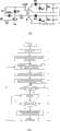
图6为本发明的控制方法流程图。Fig. 6 is a flow chart of the control method of the present invention.
图7为本发明的软投入控制得到的电流波形图。Fig. 7 is a current waveform diagram obtained by the soft input control of the present invention.
具体实施方式Detailed ways
下面通过具体实施方式和附图对本发明作进一步详细说明。The present invention will be further described in detail below through specific embodiments and accompanying drawings.
图1a是一种典型的抽油机电动机负载电源软投入的主电路图,其中KM是接触器,U1-U2,V1-V2,W1-W2分别是电动机的三相绕组,反并联的可控硅模块SCR1,SCR2,SCR3以三角形接法与绕组内接。Figure 1a is the main circuit diagram of a typical oil pumping unit motor load power supply soft input, in which KM is the contactor, U1-U2, V1-V2, W1-W2 are the three-phase windings of the motor, anti-parallel thyristor The modules SCR1, SCR2, and SCR3 are internally connected to the winding in a delta connection.
检测单元100检测三个绕组的电流和ABC三相电压,用于主控制单元203判断抽油机通断电时刻;检测单元100还通过电压互感器测量断电后定子绕组残压UW1-W2,用于判断断电后转子转速何时达到同步速。The
主控制单元203控制可控硅驱动单元向可控硅模块发出触发脉冲,通电初始瞬间实施快速软投入,通电期间全投入。人机界面101用于设定电机参数。The
图1b是电动机绕组三角形接法的另一种接线形式,其中可控硅直接串接到电源与角接的电动机绕组之间,称为可控硅与绕组外接。Figure 1b is another connection form of the delta connection of the motor winding, in which the thyristor is directly connected in series between the power supply and the delta-connected motor winding, which is called the external connection of the thyristor and the winding.
图1c是电动机绕组星形接法的一种主电路接线形式,其中可控硅串接在电源与星接的电动机绕组之间。Figure 1c is a main circuit wiring form of the motor winding star connection, in which the thyristor is connected in series between the power supply and the star-connected motor winding.
图1b和图1c的控制部分电路与图1a相同,只是单片机主控制器针对各种不同的主电路接线方式,软件上分别设置不同的可控硅软投入触发角度和触发顺序。The control part circuits in Fig. 1b and Fig. 1c are the same as those in Fig. 1a, except that the main controller of the single-chip microcomputer sets different SCR soft-in trigger angles and trigger sequences in the software for various main circuit wiring modes.
参照图4,图4是主控制器200(采用单片机AVR8535)的对应输出输入端口的接线图。其中管脚40接收来自图4电路的残压信号,送给单片机AVR8535的内置AD转换器201,转换为数字量后经计算得到电动机转速。PC0~PC2是单片机的I/O口,设置为输出,向可控硅触发驱动单元输出触发信号。Referring to FIG. 4 , FIG. 4 is a wiring diagram of the corresponding output and input ports of the main controller 200 (using the single-chip microcomputer AVR8535). Among them, the
参照图5,图5是可控硅驱动单元的触发部分主电路图。图中IN端是脉冲输入端,信号来自于脉冲发生电路,每一路(分别触发每相可控硅)由CPU的PC0~PC2引脚开通送入IN端,脉冲经高频开关元件V送到脉冲变压器B,高频脉冲变压器B将脉冲隔离变换为两路信号分别发送到可控硅模块SCR的两个可控硅的门极和阴极,导通该相的可控硅开关。Referring to FIG. 5 , FIG. 5 is a main circuit diagram of the trigger part of the thyristor drive unit. In the figure, the IN terminal is the pulse input terminal. The signal comes from the pulse generating circuit. Each channel (triggering each phase of the thyristor separately) is sent to the IN terminal by the PC0~PC2 pins of the CPU, and the pulse is sent to the IN terminal through the high-frequency switching element V. Pulse transformer B, high-frequency pulse transformer B converts pulse isolation into two-way signals and sends them to the gate and cathode of the two thyristors of the thyristor module SCR, and turns on the thyristor switch of this phase.
参照图2,图2是残压信号调理电路图,其中A为运算放大器;pt1来自电压互感器的输出端,而电压互感器的输入端接到在图1a~图1e所示电路图的W1与W2两处;信号经过运算放大器放大后,经IN1端接到图4所示主控制器200(单片机AVR8535)的对应输入端口(8535的第40引脚PA7)。图7中单片机的内置AD转换器201将信号转换为数字量,采样计算得到残压频率f,用公式n=60f/p(p为电动机的极对数)计算电动机的实时转速N。Referring to Figure 2, Figure 2 is a residual voltage signal conditioning circuit diagram, in which A is an operational amplifier; pt1 comes from the output terminal of the voltage transformer, and the input terminal of the voltage transformer is connected to W1 and W2 in the circuit diagram shown in Figure 1a ~ Figure 1e Two places; after the signal is amplified by the operational amplifier, it is connected to the corresponding input port (the 40th pin PA7 of the 8535) of the main controller 200 (single-chip microcomputer AVR8535) shown in FIG. 4 through the IN1 terminal. The built-in
参照图1a、图3、图6所示,抽油机电动机的断续供电及电源软投入控制方法流程步骤如下:Referring to Fig. 1a, Fig. 3, and Fig. 6, the flow steps of the intermittent power supply of the pumping unit motor and the soft input control method of the power supply are as follows:
步骤1:通电运行;步骤2:单片机主控制器200通过电压互感器和电流传感器测定抽油机整周期的功率曲线,确定断续供电运行方式;步骤3:通电期间判断出断电位置和时刻;步骤4:到达可以断电的时刻停发可控硅的触发脉冲;Step 1: Power-on operation; Step 2: The single-chip
步骤5:断电后电动机转速跟随负载变化而变化,转速N将先升高后降低,此时通过残压检测电路按上一段所描述的方法测量电动机转速;步骤6:判断转速升高后下降;步骤7和8:判断转速是否接近同步转速N1;步骤9:触发角度在30°~150°的范围之间进行有效地调整,从软投入控制的初始触发到最终全投入可以在5~15个周波内快速完成。步骤10:最后当触发角调整到α<
参照图1a、图7所示,当初始条件为同步速和残压为零时,反并联可控硅组SCR1中反向的晶闸管在Uab电压过零后α=80°时开始触发,之后停止触发脉冲等待电流过零时自动关断,这样可以控制Iab正向的冲击电流;图1a中SCR1正向的晶闸管比反向的晶闸管落后180°触发(α=260°),而SCR2和SCR3的正反向晶闸管的触发角度分别比SCR1落后120°和240°;SCR1的软投入触发角度约在30°~150°的范围之间进行有效地调整,最后当触发角调整到α<

Claims (1)


Priority Applications (1)
| Application Number | Priority Date | Filing Date | Title |
|---|---|---|---|
| CN2007101778087ACN101207352B (en) | 2007-11-21 | 2007-11-21 | Control method and control device of power supply soft launch for intermittent power supply by balance beam type pumping unit |
Applications Claiming Priority (1)
| Application Number | Priority Date | Filing Date | Title |
|---|---|---|---|
| CN2007101778087ACN101207352B (en) | 2007-11-21 | 2007-11-21 | Control method and control device of power supply soft launch for intermittent power supply by balance beam type pumping unit |
Publications (2)
| Publication Number | Publication Date |
|---|---|
| CN101207352A CN101207352A (en) | 2008-06-25 |
| CN101207352Btrue CN101207352B (en) | 2012-07-04 |
Family
ID=39567297
Family Applications (1)
| Application Number | Title | Priority Date | Filing Date |
|---|---|---|---|
| CN2007101778087AExpired - Fee RelatedCN101207352B (en) | 2007-11-21 | 2007-11-21 | Control method and control device of power supply soft launch for intermittent power supply by balance beam type pumping unit |
Country Status (1)
| Country | Link |
|---|---|
| CN (1) | CN101207352B (en) |
Cited By (1)
| Publication number | Priority date | Publication date | Assignee | Title |
|---|---|---|---|---|
| US9240745B2 (en) | 2009-09-08 | 2016-01-19 | The Powerwise Group, Inc. | System and method for saving energy when driving masses having periodic load variations |
Families Citing this family (11)
| Publication number | Priority date | Publication date | Assignee | Title |
|---|---|---|---|---|
| US8085009B2 (en) | 2007-08-13 | 2011-12-27 | The Powerwise Group, Inc. | IGBT/FET-based energy savings device for reducing a predetermined amount of voltage using pulse width modulation |
| US8619443B2 (en) | 2010-09-29 | 2013-12-31 | The Powerwise Group, Inc. | System and method to boost voltage |
| US8698447B2 (en) | 2007-09-14 | 2014-04-15 | The Powerwise Group, Inc. | Energy saving system and method for devices with rotating or reciprocating masses |
| MX2012003008A (en) | 2009-09-08 | 2012-04-19 | Powerwise Group Inc | Energy saving system and method for devices with rotating or reciprocating masses. |
| CN102255590B (en)* | 2011-07-20 | 2012-12-26 | 沈阳永磁电机制造有限公司 | Adaptive permanent magnet brushless DC motor macrocontrol system for beam-pumping unit |
| CN102412766B (en)* | 2011-11-18 | 2014-03-26 | 华北电力大学 | All-solid-state control device and method for star-delta soft handover of three-phase motor winding |
| CN104378043B (en)* | 2014-11-21 | 2019-08-13 | 北京智科天合科技有限公司 | A kind of electricity-saving appliance and a kind of power-saving method for threephase asynchronous machine |
| CN105915149B (en)* | 2016-05-03 | 2018-07-31 | 华北电力大学 | The accurate discrimination method of motor speed after being powered off in discontinuous power supply Energy Saving Control |
| CN105871287B (en)* | 2016-05-03 | 2018-07-31 | 华北电力大学 | Electric motor circuit breaking moment accurate determination method in discontinuous power supply Energy Saving Control |
| CN107842489B (en)* | 2016-09-19 | 2019-07-05 | 中国石油化工股份有限公司 | A kind of motor speed method of adjustment of beam pumping unit |
| CN110543116A (en)* | 2019-08-23 | 2019-12-06 | 华耀时代(天津)科技有限公司 | Tail walking beam ground control device |
Citations (3)
| Publication number | Priority date | Publication date | Assignee | Title |
|---|---|---|---|---|
| US6599095B1 (en)* | 1999-04-28 | 2003-07-29 | Kabushiki Kaisha Yaskawa Denki | Pump-off control method of pump jack |
| CN1688099A (en)* | 2005-04-30 | 2005-10-26 | 华北电力大学(北京) | Discontinuous power supply full-automatic controlling method and apparatus for motor of beam-pumping unit |
| CN2785254Y (en)* | 2005-04-30 | 2006-05-31 | 华北电力大学(北京) | Oil extractor motor discontinuous electricity use combination star angle convert controlling equipment |
- 2007
- 2007-11-21CNCN2007101778087Apatent/CN101207352B/ennot_activeExpired - Fee Related
Patent Citations (3)
| Publication number | Priority date | Publication date | Assignee | Title |
|---|---|---|---|---|
| US6599095B1 (en)* | 1999-04-28 | 2003-07-29 | Kabushiki Kaisha Yaskawa Denki | Pump-off control method of pump jack |
| CN1688099A (en)* | 2005-04-30 | 2005-10-26 | 华北电力大学(北京) | Discontinuous power supply full-automatic controlling method and apparatus for motor of beam-pumping unit |
| CN2785254Y (en)* | 2005-04-30 | 2006-05-31 | 华北电力大学(北京) | Oil extractor motor discontinuous electricity use combination star angle convert controlling equipment |
Cited By (1)
| Publication number | Priority date | Publication date | Assignee | Title |
|---|---|---|---|---|
| US9240745B2 (en) | 2009-09-08 | 2016-01-19 | The Powerwise Group, Inc. | System and method for saving energy when driving masses having periodic load variations |
Also Published As
| Publication number | Publication date |
|---|---|
| CN101207352A (en) | 2008-06-25 |
Similar Documents
| Publication | Publication Date | Title |
|---|---|---|
| CN101207352B (en) | Control method and control device of power supply soft launch for intermittent power supply by balance beam type pumping unit | |
| CN101734379B (en) | FPGA-based highly-integrated high-precision control system for micro flywheel | |
| CN101900153A (en) | Energy-saving hydraulic power source driven by permanent magnet servo motor | |
| CN107743001B (en) | Load simulation method, frequency converter, load simulator and static frequency conversion starting system | |
| CN104883107B (en) | A dynamic starting control method for a three-stage electric excitation synchronous motor | |
| CN101599733A (en) | A Phase Closed Loop Control Method for Speed Regulation of DC Motor | |
| WO2010124582A1 (en) | Pumping unit system and electricity-saving control method thereof | |
| CN101227161A (en) | Switched Reluctance Motor Control ASIC | |
| CN105021987B (en) | The method of Three-phase Asynchronous Motor Efficiency characteristic test | |
| CN101236435A (en) | Control Method of Permanent Magnet Synchronous Motor Position Servo System | |
| CN206004563U (en) | A kind of brushless DC motor without position sensor commutation phase System with Real-Time | |
| CN105915149B (en) | The accurate discrimination method of motor speed after being powered off in discontinuous power supply Energy Saving Control | |
| CN201616805U (en) | Phase control power-saving control circuit used for asynchronous motor | |
| CN201290092Y (en) | Pressure-regulating and energy-saving controller for asynchronous motor | |
| CN201118513Y (en) | Efficiency Optimization Control System of Three-phase Induction Motor | |
| CN202282754U (en) | High-voltage motor soft starting device implemented by finished low-voltage motor soft starter | |
| CN102522942A (en) | Excitation control method of doubly-fed wind-driven generator | |
| CN103414421A (en) | Method for suppressing brushless direct current motor phase change torque fluctuation based on Bang-bang control | |
| CN102361424B (en) | A Soft Starter for Asynchronous Motor Based on Fuzzy Control Strategy | |
| CN101119088A (en) | Whole controlled energy feedback system | |
| CN106385217A (en) | Frequency converter control method and control device | |
| CN104333287B (en) | A kind of DSP vector control system pulsewidth modulation pol-icy code performs Method Of Time Measurement | |
| TWI397500B (en) | Elevator energy saving device | |
| CN103633901A (en) | Control method of high-voltage brushless direct-current motor for aviation pump | |
| CN210745044U (en) | SRM direct instantaneous torque control system based on novel multi-level power circuit |
Legal Events
| Date | Code | Title | Description |
|---|---|---|---|
| C06 | Publication | ||
| PB01 | Publication | ||
| C10 | Entry into substantive examination | ||
| SE01 | Entry into force of request for substantive examination | ||
| C14 | Grant of patent or utility model | ||
| GR01 | Patent grant | ||
| C17 | Cessation of patent right | ||
| CF01 | Termination of patent right due to non-payment of annual fee | Granted publication date:20120704 Termination date:20131121 |