CN101206346A - optical module - Google Patents
optical moduleDownload PDFInfo
- Publication number
- CN101206346A CN101206346ACNA2007101959788ACN200710195978ACN101206346ACN 101206346 ACN101206346 ACN 101206346ACN A2007101959788 ACNA2007101959788 ACN A2007101959788ACN 200710195978 ACN200710195978 ACN 200710195978ACN 101206346 ACN101206346 ACN 101206346A
- Authority
- CN
- China
- Prior art keywords
- optical lens
- light source
- point light
- optical module
- cross
- Prior art date
- Legal status (The legal status is an assumption and is not a legal conclusion. Google has not performed a legal analysis and makes no representation as to the accuracy of the status listed.)
- Granted
Links
Images


Classifications
- G—PHYSICS
- G02—OPTICS
- G02B—OPTICAL ELEMENTS, SYSTEMS OR APPARATUS
- G02B19/00—Condensers, e.g. light collectors or similar non-imaging optics
- G02B19/0033—Condensers, e.g. light collectors or similar non-imaging optics characterised by the use
- G02B19/0047—Condensers, e.g. light collectors or similar non-imaging optics characterised by the use for use with a light source
- G02B19/0061—Condensers, e.g. light collectors or similar non-imaging optics characterised by the use for use with a light source the light source comprising a LED
- G02B19/0066—Condensers, e.g. light collectors or similar non-imaging optics characterised by the use for use with a light source the light source comprising a LED in the form of an LED array
- G—PHYSICS
- G02—OPTICS
- G02B—OPTICAL ELEMENTS, SYSTEMS OR APPARATUS
- G02B19/00—Condensers, e.g. light collectors or similar non-imaging optics
- G02B19/0004—Condensers, e.g. light collectors or similar non-imaging optics characterised by the optical means employed
- G02B19/0028—Condensers, e.g. light collectors or similar non-imaging optics characterised by the optical means employed refractive and reflective surfaces, e.g. non-imaging catadioptric systems
- G—PHYSICS
- G02—OPTICS
- G02B—OPTICAL ELEMENTS, SYSTEMS OR APPARATUS
- G02B19/00—Condensers, e.g. light collectors or similar non-imaging optics
- G02B19/0033—Condensers, e.g. light collectors or similar non-imaging optics characterised by the use
- G02B19/0047—Condensers, e.g. light collectors or similar non-imaging optics characterised by the use for use with a light source
- H—ELECTRICITY
- H10—SEMICONDUCTOR DEVICES; ELECTRIC SOLID-STATE DEVICES NOT OTHERWISE PROVIDED FOR
- H10H—INORGANIC LIGHT-EMITTING SEMICONDUCTOR DEVICES HAVING POTENTIAL BARRIERS
- H10H20/00—Individual inorganic light-emitting semiconductor devices having potential barriers, e.g. light-emitting diodes [LED]
- H10H20/80—Constructional details
- H10H20/85—Packages
- H10H20/855—Optical field-shaping means, e.g. lenses
Landscapes
- Physics & Mathematics (AREA)
- General Physics & Mathematics (AREA)
- Optics & Photonics (AREA)
- Planar Illumination Modules (AREA)
Abstract
Translated fromChinese
Description
Translated fromChinese本非临时申请要求享有35U.S.C.§119(a)下,2006年12月19号在韩国提交的No.2006-0129743专利申请的权益,这里引入其全部内容作为参考。This non-provisional application claims the benefit of Patent Application No. 2006-0129743 filed in Korea on December 19, 2006 under 35 U.S.C. §119(a), the entire contents of which are incorporated herein by reference.
发明领域field of invention
本发明涉及适用于液晶显示器背光单元的光模块。The invention relates to a light module suitable for a liquid crystal display backlight unit.
背景技术Background technique
随着信息技术的发展,作为用户和信息之间连接媒体的显示器的市场也越来越大。因此,平板显示器(FPD)诸如液晶显示器(LCD)、有机发光二极管(OLED)和等离子显示板(PDP)的需求也增加了。其中,能够实现高分辨率并在尺寸上能大能小的液晶显示器被广泛使用。With the development of information technology, the market for displays as a connecting medium between users and information is also growing. Accordingly, demand for flat panel displays (FPDs) such as liquid crystal displays (LCDs), organic light emitting diodes (OLEDs) and plasma display panels (PDPs) has also increased. Among them, a liquid crystal display capable of achieving high resolution and capable of being large or small in size is widely used.
液晶显示器利用液晶的光电特性来显示图像。Liquid crystal displays use the photoelectric properties of liquid crystals to display images.
因为这个原因,液晶显示器可以包括液晶板和背光单元。液晶板可以利用背光单元提供的光线显示图像。For this reason, a liquid crystal display may include a liquid crystal panel and a backlight unit. The liquid crystal panel can display images using the light provided by the backlight unit.
背光单元可以设置在液晶板下面给液晶板提供光线。这样的背光单元根据光源的位置可以分为边缘型和直接型。A backlight unit may be disposed under the liquid crystal panel to provide light to the liquid crystal panel. Such a backlight unit may be classified into an edge type and a direct type according to a position of a light source.
边缘型背光单元指的是光源设置在临近液晶板侧面的背光单元。在边缘型背光单元中,从光源发出的光可以被安放在液晶板后面的光导板引导,然后提供给液晶板。The edge type backlight unit refers to a backlight unit in which the light source is arranged near the side of the liquid crystal panel. In an edge type backlight unit, light emitted from a light source may be guided by a light guide plate disposed behind a liquid crystal panel, and then supplied to the liquid crystal panel.
由于它具有薄这一优势,边缘型背光单元主要用作小型到中型液晶显示器。Because of its thinness, the edge type backlight unit is mainly used for small to medium-sized LCDs.
直接型背光单元指的是具有设置在液晶板背面的多个光源的背光单元。综上所述,在直接型背光单元中,光源设置在液晶板后面,因此从光源发出的光不需要光导板就能直接照射到液晶板上。直接型背光单元包括设置在液晶板后面的散射板,防止通过液晶板看到光源形状。A direct type backlight unit refers to a backlight unit having a plurality of light sources disposed on the back of a liquid crystal panel. To sum up, in the direct type backlight unit, the light source is arranged behind the liquid crystal panel, so the light emitted from the light source is directly irradiated onto the liquid crystal panel without the need of a light guide plate. The direct type backlight unit includes a diffusion plate disposed behind the liquid crystal panel to prevent the shape of the light source from being seen through the liquid crystal panel.
跟边缘型背光单元相比,直接型背光单元能利用很多光源,因此主要用作有高强度需求的大尺寸液晶显示器。Compared with the edge type backlight unit, the direct type backlight unit can utilize many light sources, so it is mainly used for large-sized liquid crystal displays that require high intensity.
按照惯例,冷阴极荧光灯(CCFL)有稳定的照明和亮度特性并发出白光。这些冷阴极荧光灯(CCFL)通常用作边缘型和直接型背光单元的光源。Conventionally, cold cathode fluorescent lamps (CCFLs) have stable lighting and brightness characteristics and emit white light. These cold cathode fluorescent lamps (CCFLs) are generally used as light sources of edge type and direct type backlight units.
然而,冷阴极荧光灯(CCFL)在变薄限制上存在困难,需要高功耗,而且色彩再现性低。However, cold cathode fluorescent lamps (CCFLs) have difficulties in thinning limits, require high power consumption, and have low color reproducibility.
因此,近年来,点光源已用作边缘型和直接型背光单元中的光源。这里,点光源可以包括,例如,红/绿/蓝发光二极管(LED)。从红/绿/蓝发光二极管发出的单色光分别与液晶板的滤色镜匹配,这样能提高色彩再现性。Therefore, in recent years, point light sources have been used as light sources in edge type and direct type backlight units. Here, the point light sources may include, for example, red/green/blue light emitting diodes (LEDs). The monochromatic light emitted from the red/green/blue LEDs are respectively matched with the color filters of the liquid crystal panel, which improves the color reproducibility.
然而,点光源发出的光坦率强,因此点光源不单独使用,而是与光学透镜一起使用以折射从点光源发出的入射光并将折射后的光发送出去。换句话说,点光源和光学透镜可配置在一个封装里。下面将参考图1对光学透镜作更多具体的描述。However, the light from the point light source is straight and strong, so the point light source is not used alone, but is used together with an optical lens to refract the incident light from the point light source and send the refracted light out. In other words, point light sources and optical lenses can be configured in one package. The optical lens will be described in more detail below with reference to FIG. 1 .
图1是示意性示出传统光学透镜的透视图。FIG. 1 is a perspective view schematically showing a conventional optical lens.
参考图1,传统光学透镜30能够对设置在下面的点光源发出的入射光进行均匀折射并发送出去。这里,光学透镜30对点光源发出的入射光均匀折射并发送出去是为了通过在任一方向角度发出光线,依靠方向角度确保亮度均匀分布。Referring to FIG. 1 , a conventional
这样,光学透镜30可以包括在顶部以倒锥的形状形成并暴露于外界的外部曲面40。这个外部曲面40可以根据观察外部曲面40的方向均匀的形成。换句话说,不管在哪个方向以直角切开光学透镜30,通过光学透镜,以直角在横截面观察到的外部曲面形状可能都一样。As such, the
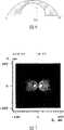
图2是利用图1中示出的光学透镜模拟色彩混合程度的结果图。FIG. 2 is a graph showing the result of simulating the degree of color mixing using the optical lens shown in FIG. 1 .
如图2所示,如果光学透镜30的外部曲面40是均匀形成的,包括红/绿/蓝发光二极管的点光源发出的单色光的色彩混合程度将降低。由于这一点,在具有带均匀形成的外部曲面40的光学透镜30的边缘型背光单元中,存在设置在临近光学透镜30的光导板的光入射部分亮度不均的问题。而且,边缘型背光单元可能具有低光效的问题。这是由于在边缘型背光单元中,光学透镜30设置在靠近光导板的光入射部分,因此不需要从各个方向发出的任一光线。As shown in FIG. 2, if the outer
同时,在具有含均匀形成的外部曲面40的光学透镜30的直接型背光单元中,存在需要在光学透镜30和散射板之间另外安排散射部分以提高色彩混合度的问题。由于这个原因,在实现直接型背光单元的薄化时可能存在局限性。而且,在直接型背光单元中,点光源发出的光可能会横向倾斜。因此,直接型背光单元存在需要增加散射板的浑浊(haze)工艺以在直角方向引导光线的问题。这可能导致直接型背光单元的低光效问题。Meanwhile, in the direct type backlight unit having the
发明内容Contents of the invention
本发明是为了解决上述问题。因此,本文献提供光模块是一个优势,能根据方向角度实现非均匀亮度分布。The present invention is to solve the above-mentioned problems. Therefore, it is an advantage that this document provides light modules that can achieve non-uniform brightness distribution according to the direction angle.
本文献的另一个目的是提供光模块,通过实现在方向角度上亮度的非均匀分布提高色彩混合度。Another object of this document is to provide a light module that improves color mixing by achieving a non-uniform distribution of luminance in directional angles.
本文献还有另外一个目的是提供光模块,通过实现在方向角度上亮度的非均匀分布提高光效。Another purpose of this document is to provide an optical module that improves light efficiency by realizing non-uniform distribution of brightness in direction and angle.
本发明还有另一个目的是提供光模块,通过实现在方向角度上亮度的非均匀分布实现背光单元的薄化。Yet another object of the present invention is to provide an optical module that realizes thinning of the backlight unit by realizing non-uniform distribution of luminance in directional angles.
本发明要实现的目标不限于上述方面,通过下面给出的描述,其它没有提到的方面对于本领域的技术人员来说也显而易见。The objectives to be achieved by the present invention are not limited to the above aspects, and other unmentioned aspects will also be apparent to those skilled in the art through the description given below.
为了实现上述目标,根据本发明的一个方面提供了一个光模块,包括:点光源,和用空气层将其与点光源隔离开并不均匀折射和发送来自点光源的入射光的光学透镜。In order to achieve the above object, an optical module is provided according to one aspect of the present invention, including: a point light source, and an optical lens that isolates it from the point light source by an air layer and refracts and transmits incident light from the point light source uniformly.
点光源设置在带有空气层的光学透镜的内部空间。The point light source is arranged in the inner space of the optical lens with the air layer.
根据本发明的另一方面,光模块包括:点光源;和靠近点光源形成的光学透镜,其具有沿着彼此正交的轴线获得的横截面观察在形状方面不同的外表面,以不均匀折射来自点光源的入射光。According to another aspect of the present invention, the optical module includes: a point light source; and an optical lens formed close to the point light source, which has outer surfaces different in shape as viewed in a cross-section taken along axes orthogonal to each other, to refract non-uniformly Incident light from a point light source.
依照本发明,非均匀亮度分布能够通过具有不均匀形状的光学透镜实现。因此可能提高色彩混合度、光效并实现背光单元的薄化。According to the present invention, a non-uniform brightness distribution can be realized by an optical lens having a non-uniform shape. It is thus possible to improve the degree of color mixing, light efficiency, and achieve thinning of the backlight unit.
其它实施例的详细资料包含在详细描述和附图中。Details of other embodiments are included in the detailed description and drawings.
附图说明Description of drawings
本文献的执行将参考下面的附图详细说明,其中相似的元件用相同的数字表示。The implementation of this document will be described in detail with reference to the following figures in which like elements are designated by like numerals.
图1是示意性的示出传统透镜的透视图;FIG. 1 is a perspective view schematically showing a conventional lens;
图2示出了利用图1中所示的透镜模拟色彩混合度的结果;Figure 2 shows the results of simulating the degree of color mixing using the lenses shown in Figure 1;
图3是根据本发明的第一实施例示出光学透镜的透视图;3 is a perspective view illustrating an optical lens according to a first embodiment of the present invention;
图4是沿着图3中线IV-IV′的透视图;Fig. 4 is a perspective view along line IV-IV' in Fig. 3;
图5是沿着图3中线IV-IV′的横截面图;Fig. 5 is a cross-sectional view along line IV-IV' in Fig. 3;
图6是沿着图3中线VI-VI′的横截面图;Fig. 6 is a cross-sectional view along line VI-VI' in Fig. 3;
图7是利用图3中所示的光学透镜模拟亮度分布的结果;Figure 7 is the result of simulating the brightness distribution using the optical lens shown in Figure 3;
图8是利用图3中所示的光学透镜模拟色彩混合度的结果;Fig. 8 is the result of using the optical lens shown in Fig. 3 to simulate the degree of color mixing;
图9是根据本发明的第二实施例示出光学透镜的透视图;9 is a perspective view illustrating an optical lens according to a second embodiment of the present invention;
图10是沿着图9中线X-X′的透视图;Figure 10 is a perspective view along line X-X' in Figure 9;
图11是沿着图9中线X-X′的横截面图;Fig. 11 is a cross-sectional view along line X-X' in Fig. 9;
图12是沿着图9中线XII-XII′的横截面图;Fig. 12 is a cross-sectional view along line XII-XII' in Fig. 9;
图13是示意性示出具有图3中光学透镜的光模块的横截面图;Fig. 13 is a cross-sectional view schematically showing an optical module with an optical lens in Fig. 3;
图14是示意性示出具有图9中光学透镜的光模块的横截面图;Fig. 14 is a cross-sectional view schematically showing an optical module with an optical lens in Fig. 9;
图15是示意性示出具有图13所示光模块的背光单元的分解透视图。FIG. 15 is an exploded perspective view schematically showing a backlight unit having the light module shown in FIG. 13 .
具体实施方式Detailed ways
参考附图和下面详细描述的示意性实施例,本发明的优势和特点以及实现优势和特点的方法很明显。Advantages and features of the present invention and a method of achieving them will be apparent with reference to the accompanying drawings and the exemplary embodiments described in detail below.
下面,依据本发明的示意性实施例,参考附图详细描述光学透镜、具有光学透镜的光模块以及具有光模块的背光单元。Hereinafter, according to exemplary embodiments of the present invention, an optical lens, an optical module with the optical lens, and a backlight unit with the optical module will be described in detail with reference to the accompanying drawings.
图3是根据本发明的第一实施例示出光学透镜的透视图。图4是沿着图3中线IV-IV’获得的透视图。图5是沿着图3中线IV-IV’获得的横截面图。图6是沿着图3中线VI-VI’获得的横截面图。Fig. 3 is a perspective view showing an optical lens according to a first embodiment of the present invention. Fig. 4 is a perspective view taken along line IV-IV' in Fig. 3 . Fig. 5 is a cross-sectional view taken along line IV-IV' in Fig. 3 . Fig. 6 is a cross-sectional view taken along line VI-VI' in Fig. 3 .
参考图3到图6,根据本发明的第一实施例可以形成光学透镜130,压低光学透镜130较低部分的一部分以在下面形成的点光源和光学透镜130之间形成空气层。为了产生白光,点光源可以包括红/绿/蓝光电二极管。在点光源和光学透镜130之间形成空气层的原因是确保一段距离,使点光源发出的光在到达光学透镜130之前有些散射。由于空气层的存在,点光源以预知的距离与光学透镜130隔离开。Referring to FIGS. 3 to 6 , the
通过现有存在的空气层,光学透镜130能够不均匀折射来自点光源的入射光并发送出去。这里,光学透镜130不均匀折射并发送来自点光源的入射光的原因是根据方向角度确保非均匀亮度分布。因为这个原因,光学透镜130可以包括暴露于空气层的内表面132,因为光学透镜130较低部分的部分被拉低,和暴露于外界的外表面140。Through the existing air layer, the
通过存在于光学透镜130内部的空气层,内表面132能不均匀折射来自点光源的折射光。这样,通过光学透镜130,分别沿着第一和第二方向,在直角获得的截面图上观察到的内表面132形状可能不同。换句话说,根据观察内表面132的方向,内表面132可以不均匀的形成。The
例如,如图5所示,可以通过光学透镜130,沿着第一方向也就是线IV-IV′的方向,以直角获得的横截面上相交于一点的第一直线134和第二直线136的形式观察内表面132。而且,如图6所示,可以通过光学透镜130,沿着第二方向也就是线VI-VI′的方向,以直角获得的横截面上半圆曲面138的形式观察内表面132。这里,点光源可以在沿着线VI-VI’的方向排成一排。For example, as shown in FIG. 5, the first
或者,可以通过光学透镜沿着第一方向,以直角获得的横截面上相交于一点的第一直线134和第二直线136的形式观察内表面132,也可以通过光学透镜130沿着第二方向,以直角获得的横截面上椭圆曲面的形式观察内表面。第一和第二方向分别为沿着线IV-IV′和VI-VI’的方向。Alternatively, the
外表面140能够再一次折射内表面132折射过的光线。这样,外表面可以以半球状表面或椭圆体表面的形式形成。光学透镜的厚度,也就是内表面132和外表面140之间的距离,会根据内表面132和外表面140之间形状的不同而变化。这样,根据位置点光源发出的入射光和通过光学透镜130的光线可能出现程差。这可能导致通过光学透镜130的光线进一步的散射。The
内表面132和外表面140种的至少一个会被浑浊化(hazed),这是为了通过浑浊化内表面132和外表面140中的至少一个,进一步散射通过光学透镜130发出的光线。At least one of
光学透镜130可以由透明材料组成,诸如聚碳酸酯(PC)和聚甲基丙烯酸甲酯(PMMA),因为从点光源发出的光需要通过光学透镜130发射。The
图7是利用图3中所示光学透镜模拟亮度分布的结果图。图8是利用图3中所示光学透镜模拟色彩混合度的结果图。FIG. 7 is a graph showing the result of simulating the brightness distribution using the optical lens shown in FIG. 3 . FIG. 8 is a graph showing the result of simulating the degree of color mixing using the optical lens shown in FIG. 3 .
如图7所示,假设利用光学透镜130仿真,根据方向角度可以看到非均匀亮度分布。确切的说,虽然光线是从X轴大约-40度到+40度的方向发出去的,在超出上述光线范围的方向上没有光线发出。这里,点光源可以沿着Y轴方向排成一列。As shown in FIG. 7 , assuming that the
由于这个原因,如果使用红/绿/蓝发光二极管,所有的红/绿/蓝发光二极管能够在上述角度范围内发出光线。因此,如图8所示,可以在垂直方向提高色彩亮度。红/绿/蓝发光二极管可以沿着水平方向排成一列。这样,可以提高使用光模块110的背光单元的光效并实现背光单元的薄化,其中光模块含有光学透镜130。For this reason, if red/green/blue LEDs are used, all red/green/blue LEDs are able to emit light in the above-mentioned angular range. Therefore, as shown in FIG. 8, color brightness can be increased in the vertical direction. Red/green/blue LEDs can be arranged in a horizontal row. In this way, the light efficiency of the backlight unit using the
图9是根据本发明的第二实施例光学透镜的透视图。图10是沿着图9中线X-X’得到的透视图。图11是沿着图9中线X-X′得到的横截面图。图12是沿着图9中线XII-XII’方向得到的横截面图。图9中线X-X′和线XII-XII′互相正交。Fig. 9 is a perspective view of an optical lens according to a second embodiment of the present invention. Fig. 10 is a perspective view taken along line XX' in Fig. 9 . Fig. 11 is a cross-sectional view taken along line XX' in Fig. 9 . Fig. 12 is a cross-sectional view taken along line XII-XII' in Fig. 9 . In Fig. 9, the line X-X' and the line XII-XII' are orthogonal to each other.
参考图9到图12,根据本发明的第二实施例,光学透镜230能够不均匀的折射并发送来自点光源的入射光,点光源在光学透镜靠近中央的较低部分形成。光学透镜230不均匀折射和发射来自点光源的入射光的原因是确保根据方向角度非均匀亮度分布。这里,为了产生白光,点光源可以包括红/绿/蓝发光二极管。Referring to FIGS. 9 to 12, according to the second embodiment of the present invention, the
综上所述,光学透镜230和点光源可看作一个整体,因为他们在彼此靠近的地方形成。To sum up, the
光学透镜230可以包括暴露于外界的外表面240,以非均匀的折射和发射来自点光源的入射光。The
外表面240能通过内表面232非均匀折射和发射来自点光源的入射光,其中内表面232在靠近点光源的光学透镜240的中央的较低部分形成。The
这样,通过光学透镜230,分别沿着第三和第四方向,在以直角得到的横截面上观察到的外表面形状不同,换句话说,根据观察外表面240的方向,外表面240可以不均匀的形成。In this way, through the
例如,如图11所示,可以沿着第三方向,也就是线X-X′的方向,通过光学透镜230,以直角获得的横截面顶部下拉的半圆曲面242的形式观察外表面240。而且,如图12所示,可以沿着第四方向,也就是线XII-XII′的方向,以直角获得横截面上半圆曲面244的形式观察外表面240。For example, as shown in FIG. 11 , the
或者,可以通过光学透镜230,沿着第三方向,以直角获得的横截面顶部半圆曲面244的形式观察外表面240,也可以沿着第四方向,通过光学透镜230,以直角获得横截面上椭圆形曲面的形式观察外表面。这里,第三和第四方向分别是沿着线X-X′和线XII-XII′的方向。Or, the
外表面240可以浑浊化,这是为了通过浑浊化外表面240进一步散射通过光学透镜230发出的光线。The
光学透镜可以由透明材料组成,比如硅,因为点光源发出的光线需要通过光学透镜230发射。The optical lens can be made of a transparent material, such as silicon, because the light emitted by the point light source needs to be emitted through the
综上所述,通过具有不均匀外形的外表面240可以实现视方向角度的非均匀亮度分布。这可以提高色彩混合度和光效,并实现背光单元的薄化。To sum up, non-uniform luminance distribution in viewing direction angles can be achieved by the
图13是示意性示出图具有图3中所示光学透镜的光模块的横截面图。由于图13中所示的光学透镜与图3中一样,图3中所用的相同图标用来标示相同的元件,对结构的重复描述将省略,只描述本发明的特性。FIG. 13 is a cross-sectional view schematically showing an optical module having the optical lens shown in FIG. 3 . Since the optical lens shown in FIG. 13 is the same as that in FIG. 3, and the same symbols used in FIG. 3 are used to designate the same components, repeated description of the structure will be omitted, and only the characteristics of the present invention will be described.
参考图13,光模块110能发出不均匀的折射光。Referring to FIG. 13 , the
这样,光模块110可以包括点光源120和与点光源120隔离开的光学透镜130。同样,光学透镜110还包括反射部分150。这里,点光源120可以在光学透镜130下面形成。In this way, the
点光源120利用外界施加的驱动电压可以产生光线,并将产生的光线发射到光学透镜130。这里,点光源120可以包括红/绿/蓝发光二极管以发出白光。这里,点光源可以安放在金属核印刷电路板(MCPCB)上。这里,利用硅等能喷射成型的材料可以掩盖点光源120避免点光源120直接暴露于光学透镜中的空气层。The point
光学透镜130可以包括内表面132和外表面140,内表面132和外表面140以不均匀外形形成,以通过内部存在的空气层不均匀的折射和发射来自点光源的入射光。The
反射部分150能够反射通过光学透镜不均匀折射并发出的光线。这里,反射部分150可以由,例如铝材料构成,并可以涂敷在金属核印刷电路板上。The
图14是示意性示出具有图9中所示光学透镜的光模块的横截面图。由于图14中的光学透镜与图9中一样,图9中所用的相同的图标将用来表示相同元件,结构的重复描述将省略,只描述本发明的特性。FIG. 14 is a cross-sectional view schematically showing an optical module having the optical lens shown in FIG. 9 . Since the optical lens in FIG. 14 is the same as that in FIG. 9, the same symbols used in FIG. 9 will be used to denote the same elements, repeated description of the structure will be omitted, and only the characteristics of the present invention will be described.
参考图14,光模块110能发出不均匀折射光。Referring to FIG. 14 , the
这样,光模块110可以包括点光源120和靠近点光源120的光学透镜。这样,光模块110还可以包括反射部分150。In this way, the
点光源120利用外界施加的驱动电压可以产生光,并将光发射到光学透镜130。这里,点光源120可以包括红/绿/蓝发光二极管以产生白光。这里,点光源可以安放在金属核印刷电路板(MCPCB)上。这里,如果用硅作光学透镜230的材料,点光源220要提前准备好,然后通过硅喷射成型,这样光学透镜230和点光源彼此靠近。The point
光学透镜230可以包括暴露于外界的外表面240,以不均匀的折射和发射来自点光源220的入射光。The
反射部分250能够反射通过光学透镜230折射和发射出来的光。这里,反射部分250可以由,例如铝材料构成,并涂敷在金属核印刷电路板上。The
图15是示意性的示出具有图13所示光模块的背光单元的分解透视图。由于图15中的光学透镜与图13中一样,图9中所用的相同的图标用来标示相同的元件,结构的重复描述将省略,只描述本发明的特性。图14中所示的具有光模块的背光单元与图15中所示的背光单元相似,因此,省略其详细描述。在图15中,边缘性背光单元已作为背光单元进行了说明。这仅仅是为了根据本发明的实施例说明背光单元,无意限制。FIG. 15 is an exploded perspective view schematically showing a backlight unit having the light module shown in FIG. 13 . Since the optical lens in FIG. 15 is the same as that in FIG. 13, the same symbols used in FIG. 9 are used to designate the same components, and repeated description of the structure will be omitted, and only the characteristics of the present invention will be described. The backlight unit having the light module shown in FIG. 14 is similar to the backlight unit shown in FIG. 15, and thus, a detailed description thereof is omitted. In FIG. 15, an edge type backlight unit has been illustrated as a backlight unit. This is just to illustrate the backlight unit according to the embodiment of the present invention, and is not intended to be limiting.
参考图15,背光单元100能够给设置其上的液晶板提供光。Referring to FIG. 15, the
背光单元100可以包括光模块110、光导板170和光片180。背光单元还包括反射板190。如果背光单元100是直接型,则可以没有光导板170。The
光模块110可以包括点光源120和光学透镜130,光学透镜130与点光源120隔离开并发出不均匀光。光模块110还包括反射板190。光学透镜130的外表面140面向光导板170形成。光模块110可以沿着光导板170的一边纵向设置。点光源120可以沿着Z轴方向排成一列。未作说明的图标160标示金属核印刷电路板160并在上面安放点光源120。The
光导板170设置在靠近光模块110的地方,能够引导来自光模块110的入射光向上发射。The light guide plate 170 is disposed close to the
光片180设置在光导板170上面,能够散射和聚集通过光导板170向上发出的光,也就是,从光模块110发出的光并向上发射。光片180具有散射片、棱镜片和亮度增强片中的至少一种。The
反射板190可以设置在光导板170下面,能向上反射来自光模块中通过光导板170向下发出的光。反射板190可以由泡沫塑料,例如泡沫聚对苯二甲酸乙二醇酯构成。The reflective plate 190 may be disposed under the light guide plate 170 and can reflect upwardly the light from the optical module that is emitted downward through the light guide plate 170 . The reflection plate 190 may be made of foamed plastic, such as foamed polyethylene terephthalate.
尽管参考附图说明和描述了本发明的示意性实施例,本领域的技术人员应该理解在不改变本发明的技术精神和本质特征的情况下还可有其它的具体实施方式。Although the exemplary embodiments of the present invention have been illustrated and described with reference to the accompanying drawings, those skilled in the art should understand that there are other specific implementations without changing the technical spirit and essential features of the present invention.
因此,这些实施例只是告诉本领域的技术人员本发明的范围。这些应该理解为说明性的而不是约束,而且本发明仅由下面权利要求的范围定义。Therefore, these embodiments are only intended to inform those skilled in the art of the scope of the present invention. These are to be understood as illustrative rather than restrictive, and the invention is only to be defined by the scope of the following claims.
Claims (16)
Translated fromChineseApplications Claiming Priority (3)
| Application Number | Priority Date | Filing Date | Title |
|---|---|---|---|
| KR10-2006-0129743 | 2006-12-19 | ||
| KR1020060129743 | 2006-12-19 | ||
| KR1020060129743AKR101329413B1 (en) | 2006-12-19 | 2006-12-19 | Optical lens, optical module having the optical lens and backlight unit having the optical module |
Publications (2)
| Publication Number | Publication Date |
|---|---|
| CN101206346Atrue CN101206346A (en) | 2008-06-25 |
| CN101206346B CN101206346B (en) | 2010-07-21 |
Family
ID=39566669
Family Applications (1)
| Application Number | Title | Priority Date | Filing Date |
|---|---|---|---|
| CN2007101959788AActiveCN101206346B (en) | 2006-12-19 | 2007-12-14 | Light module |
Country Status (3)
| Country | Link |
|---|---|
| US (1) | US7837360B2 (en) |
| KR (1) | KR101329413B1 (en) |
| CN (1) | CN101206346B (en) |
Cited By (2)
| Publication number | Priority date | Publication date | Assignee | Title |
|---|---|---|---|---|
| US8167464B2 (en) | 2008-12-05 | 2012-05-01 | Au Optronics Corporation | Backlight module and light emitting diode thereof |
| WO2017113251A1 (en)* | 2015-12-30 | 2017-07-06 | 周肇梅 | Ultrathin straight-down backlight module |
Families Citing this family (30)
| Publication number | Priority date | Publication date | Assignee | Title |
|---|---|---|---|---|
| US9070850B2 (en) | 2007-10-31 | 2015-06-30 | Cree, Inc. | Light emitting diode package and method for fabricating same |
| US8669572B2 (en) | 2005-06-10 | 2014-03-11 | Cree, Inc. | Power lamp package |
| US7675145B2 (en) | 2006-03-28 | 2010-03-09 | Cree Hong Kong Limited | Apparatus, system and method for use in mounting electronic elements |
| US8748915B2 (en) | 2006-04-24 | 2014-06-10 | Cree Hong Kong Limited | Emitter package with angled or vertical LED |
| US8735920B2 (en)* | 2006-07-31 | 2014-05-27 | Cree, Inc. | Light emitting diode package with optical element |
| US9711703B2 (en)* | 2007-02-12 | 2017-07-18 | Cree Huizhou Opto Limited | Apparatus, system and method for use in mounting electronic elements |
| CN101388161A (en)* | 2007-09-14 | 2009-03-18 | 科锐香港有限公司 | LED surface mounting device and LED display incorporating the same |
| CN201141922Y (en)* | 2007-10-16 | 2008-10-29 | 东莞勤上光电股份有限公司 | secondary optical lens |
| US10256385B2 (en) | 2007-10-31 | 2019-04-09 | Cree, Inc. | Light emitting die (LED) packages and related methods |
| US8866169B2 (en)* | 2007-10-31 | 2014-10-21 | Cree, Inc. | LED package with increased feature sizes |
| TWI363907B (en) | 2008-08-05 | 2012-05-11 | Au Optronics Corp | Backlight module and light emitting diode thereof |
| US8791471B2 (en)* | 2008-11-07 | 2014-07-29 | Cree Hong Kong Limited | Multi-chip light emitting diode modules |
| US20110037083A1 (en)* | 2009-01-14 | 2011-02-17 | Alex Chi Keung Chan | Led package with contrasting face |
| US8368112B2 (en) | 2009-01-14 | 2013-02-05 | Cree Huizhou Opto Limited | Aligned multiple emitter package |
| KR101243826B1 (en)* | 2009-02-17 | 2013-03-18 | 엘지디스플레이 주식회사 | Light Emitting Diode Pakage, Method for Manufacturing the Same and Light Source Unit Having the LED Pakage |
| KR101053951B1 (en)* | 2009-07-21 | 2011-08-04 | 노명재 | Icicle type light adjustment lens for LED lighting device |
| US8186838B2 (en)* | 2009-10-05 | 2012-05-29 | Edison Opto Corporation | Optical lens |
| KR100961676B1 (en)* | 2009-11-04 | 2010-06-09 | (주) 아주광학 | Lens for led light light to realize distribution |
| JP5518881B2 (en)* | 2010-03-15 | 2014-06-11 | パナソニック株式会社 | Light emitting device, surface light source, and liquid crystal display device |
| KR101756825B1 (en) | 2010-08-24 | 2017-07-11 | 삼성전자주식회사 | Optical lens, led module and lighting apparatus having the optical lens |
| KR101109581B1 (en)* | 2010-12-01 | 2012-01-31 | 노명재 | Wide icicle type light adjusting lens for diffusing light of led |
| KR101233634B1 (en)* | 2011-09-15 | 2013-02-15 | 노명재 | Led lighting engine applied icicle type diffuser |
| KR101957184B1 (en) | 2011-12-02 | 2019-03-13 | 엘지전자 주식회사 | Backlight unit and display apparatus having the same |
| US8564004B2 (en) | 2011-11-29 | 2013-10-22 | Cree, Inc. | Complex primary optics with intermediate elements |
| KR101462510B1 (en)* | 2013-03-14 | 2014-11-20 | 에이옵틱스주식회사 | Light distribution lens for light emitting device lighting |
| KR101462511B1 (en)* | 2013-03-18 | 2014-11-20 | 에이옵틱스주식회사 | Led lens and light source module with led lens |
| US9601670B2 (en) | 2014-07-11 | 2017-03-21 | Cree, Inc. | Method to form primary optic with variable shapes and/or geometries without a substrate |
| CN104141912A (en)* | 2014-08-21 | 2014-11-12 | 深圳市华星光电技术有限公司 | Curved surface shaped backlight module and curved surface shaped liquid crystal displayer |
| US10622522B2 (en) | 2014-09-05 | 2020-04-14 | Theodore Lowes | LED packages with chips having insulated surfaces |
| CZ2017734A3 (en) | 2017-11-14 | 2019-05-22 | Varroc Lighting Systems, s.r.o. | Vehicle lighting equipment |
Family Cites Families (16)
| Publication number | Priority date | Publication date | Assignee | Title |
|---|---|---|---|---|
| JPH0750797B2 (en)* | 1985-12-13 | 1995-05-31 | 沖電気工業株式会社 | Light emitting diode |
| KR101015289B1 (en)* | 2002-11-05 | 2011-02-15 | 파나소닉 주식회사 | Light emitting diode |
| DE10336162B4 (en)* | 2003-08-07 | 2009-05-28 | Odelo Gmbh | Lighting unit with light source and light guide |
| US7473013B2 (en)* | 2003-12-10 | 2009-01-06 | Okaya Electric Industries Co., Ltd. | Indicator lamp having a converging lens |
| CA2557447C (en)* | 2004-02-26 | 2012-12-18 | Tir Systems Ltd. | Apparatus for forming an asymmetric illumination beam pattern |
| KR101085144B1 (en) | 2004-04-29 | 2011-11-21 | 엘지디스플레이 주식회사 | LED lamp unit |
| KR100616598B1 (en)* | 2004-08-11 | 2006-08-28 | 삼성전기주식회사 | Light emitting diode lens and backlight module having the same |
| JP4537822B2 (en)* | 2004-10-14 | 2010-09-08 | スタンレー電気株式会社 | Lamp |
| KR101080355B1 (en)* | 2004-10-18 | 2011-11-04 | 삼성전자주식회사 | Light emitting diode, lens for the same |
| GB2421584A (en)* | 2004-12-21 | 2006-06-28 | Sharp Kk | Optical device with converging and diverging elements for directing light |
| CN100585268C (en)* | 2005-03-07 | 2010-01-27 | 日亚化学工业株式会社 | Planar irradiation light source and planar irradiation device |
| KR101136344B1 (en)* | 2005-04-06 | 2012-04-18 | 삼성전자주식회사 | Optical lens, optical module having the optical lens, back light assembly having the optical module and display apparatus having the back light assembly |
| CN100378543C (en) | 2005-04-30 | 2008-04-02 | 巨虹电子股份有限公司 | LCD backlight source generating method |
| JP2009500662A (en)* | 2005-06-29 | 2009-01-08 | リフレキサイト・コーポレーション | Collimating microlens array |
| US20070091615A1 (en)* | 2005-10-25 | 2007-04-26 | Chi-Tang Hsieh | Backlight module for LCD monitors and method of backlighting the same |
| US7674018B2 (en)* | 2006-02-27 | 2010-03-09 | Illumination Management Solutions Inc. | LED device for wide beam generation |
- 2006
- 2006-12-19KRKR1020060129743Apatent/KR101329413B1/enactiveActive
- 2007
- 2007-12-14CNCN2007101959788Apatent/CN101206346B/enactiveActive
- 2007-12-18USUS12/000,917patent/US7837360B2/ennot_activeExpired - Fee Related
Cited By (2)
| Publication number | Priority date | Publication date | Assignee | Title |
|---|---|---|---|---|
| US8167464B2 (en) | 2008-12-05 | 2012-05-01 | Au Optronics Corporation | Backlight module and light emitting diode thereof |
| WO2017113251A1 (en)* | 2015-12-30 | 2017-07-06 | 周肇梅 | Ultrathin straight-down backlight module |
Also Published As
| Publication number | Publication date |
|---|---|
| KR101329413B1 (en) | 2013-11-14 |
| US20080198594A1 (en) | 2008-08-21 |
| CN101206346B (en) | 2010-07-21 |
| KR20080056784A (en) | 2008-06-24 |
| US7837360B2 (en) | 2010-11-23 |
Similar Documents
| Publication | Publication Date | Title |
|---|---|---|
| CN101206346A (en) | optical module | |
| CN100460949C (en) | Surface light source device, lighting unit and light beam control member | |
| KR101396658B1 (en) | Light Cube and Flat Light Unit and Liquid Crystal Display Device including the same | |
| JP4863357B2 (en) | Light emitting device, surface light source device, display device, and light flux controlling member | |
| CN101097349B (en) | Backlight assembly and liquid crystal display device using same | |
| KR100978078B1 (en) | Prism sheet and liquid crystal display device having same | |
| WO2007145248A1 (en) | Light guide plate, light guide plate assembly, and surface illuminating device and liquid crystal display device using these | |
| CN101000387A (en) | Prism and backlight module using the prism | |
| TW201009255A (en) | Light source device, lighting device, and display device | |
| US10352530B2 (en) | Lens, light emitting apparatus including the lens, and backlight unit including the apparatus | |
| CN102338904A (en) | Light guide plate and backlight unit including the light guide plate | |
| WO2011111270A1 (en) | Light guide set, illumination device, and display device | |
| TWI404893B (en) | An illuminating device without a light guide board | |
| CN102200608A (en) | Light guide plate and backlight unit | |
| TW200412443A (en) | Optical element, planar lighting unit and liquid crystal display unit | |
| CN1306329C (en) | Light source for backlight module | |
| JP4555250B2 (en) | Light guide plate and planar illumination device using the same | |
| TWM409450U (en) | Light guide plate with inner laser engraving | |
| WO2013161678A1 (en) | Illumination device and display device | |
| CN201028402Y (en) | Light uniform element of surface light source | |
| CN101017270A (en) | Optical module | |
| CN1854849A (en) | Liquid crystal display apparatus having a light guiding plate | |
| CN104216041A (en) | Light guide plate having rounded polygon pattern and liquid crystal display device having thereof | |
| CN103375705B (en) | Light source module | |
| KR20120039405A (en) | Backlight unit and liquid crystal display device having the same |
Legal Events
| Date | Code | Title | Description |
|---|---|---|---|
| C06 | Publication | ||
| PB01 | Publication | ||
| C10 | Entry into substantive examination | ||
| SE01 | Entry into force of request for substantive examination | ||
| C14 | Grant of patent or utility model | ||
| GR01 | Patent grant |