CN101204032B - Transmitting apparatus and receiving apparatus of multicarrier transmission system, and transmitting method and receiving method using multicarrier transmission system - Google Patents
Transmitting apparatus and receiving apparatus of multicarrier transmission system, and transmitting method and receiving method using multicarrier transmission systemDownload PDFInfo
- Publication number
- CN101204032B CN101204032BCN2006800224580ACN200680022458ACN101204032BCN 101204032 BCN101204032 BCN 101204032BCN 2006800224580 ACN2006800224580 ACN 2006800224580ACN 200680022458 ACN200680022458 ACN 200680022458ACN 101204032 BCN101204032 BCN 101204032B
- Authority
- CN
- China
- Prior art keywords
- mentioned
- demodulation
- modulation
- unit
- vector
- Prior art date
- Legal status (The legal status is an assumption and is not a legal conclusion. Google has not performed a legal analysis and makes no representation as to the accuracy of the status listed.)
- Expired - Fee Related
Links
Images


Classifications
- H—ELECTRICITY
- H04—ELECTRIC COMMUNICATION TECHNIQUE
- H04L—TRANSMISSION OF DIGITAL INFORMATION, e.g. TELEGRAPHIC COMMUNICATION
- H04L25/00—Baseband systems
- H04L25/02—Details ; arrangements for supplying electrical power along data transmission lines
- H04L25/03—Shaping networks in transmitter or receiver, e.g. adaptive shaping networks
- H04L25/03006—Arrangements for removing intersymbol interference
- H04L25/03343—Arrangements at the transmitter end
- H—ELECTRICITY
- H04—ELECTRIC COMMUNICATION TECHNIQUE
- H04L—TRANSMISSION OF DIGITAL INFORMATION, e.g. TELEGRAPHIC COMMUNICATION
- H04L25/00—Baseband systems
- H04L25/02—Details ; arrangements for supplying electrical power along data transmission lines
- H04L25/03—Shaping networks in transmitter or receiver, e.g. adaptive shaping networks
- H04L25/03006—Arrangements for removing intersymbol interference
- H04L25/03821—Inter-carrier interference cancellation [ICI]
- H—ELECTRICITY
- H04—ELECTRIC COMMUNICATION TECHNIQUE
- H04L—TRANSMISSION OF DIGITAL INFORMATION, e.g. TELEGRAPHIC COMMUNICATION
- H04L25/00—Baseband systems
- H04L25/02—Details ; arrangements for supplying electrical power along data transmission lines
- H04L25/03—Shaping networks in transmitter or receiver, e.g. adaptive shaping networks
- H04L25/03006—Arrangements for removing intersymbol interference
- H04L2025/0335—Arrangements for removing intersymbol interference characterised by the type of transmission
- H04L2025/03375—Passband transmission
- H04L2025/03414—Multicarrier
- H—ELECTRICITY
- H04—ELECTRIC COMMUNICATION TECHNIQUE
- H04L—TRANSMISSION OF DIGITAL INFORMATION, e.g. TELEGRAPHIC COMMUNICATION
- H04L27/00—Modulated-carrier systems
- H04L27/26—Systems using multi-frequency codes
- H04L27/2601—Multicarrier modulation systems
- H04L27/2614—Peak power aspects
- H04L27/2615—Reduction thereof using coding
Landscapes
- Engineering & Computer Science (AREA)
- Power Engineering (AREA)
- Computer Networks & Wireless Communication (AREA)
- Signal Processing (AREA)
- Digital Transmission Methods That Use Modulated Carrier Waves (AREA)
- Noise Elimination (AREA)
Abstract
Description
Translated fromChinese技术领域technical field
本发明涉及多载波传送方式,更确定地讲,涉及减轻起因于移动体通信中的传送路径响应的变动及在收发装置内产生的相位噪声等的载波间干扰的技术。 The present invention relates to a multi-carrier transmission system, and more specifically, relates to a technique for reducing inter-carrier interference caused by fluctuations in transmission path response in mobile communications and phase noise generated in a transceiver. the
背景技术Background technique
作为经由地波数字电视广播或无线LAN(Local Area Network)等、随着多路造成的延迟分散的传送路径稳定地进行通信的方法,广泛地使用以正交频率分割多路复用(OFDM:Orthogonal Frequency DivisionMultiplex,即正交频分复用)传送方式(以下称作OFDM传送方式)为代表的多载波传送方式。另一方面,在发送装置或接收装置或其两者一边移动一边进行通信的移动体通信中,发生多普勒现象带来的频率变动、起因于多路带来的延迟分散的接收信号的振幅变动。此外,在发送装置或接收装置的频率变换部中,也有因振荡电路的相位噪声而发生相位变动的情况。OFDM传送方式是将各子载波的调制波密集地多路复用以使其频率波谱相互重合而进行传送的方式。由此,在将OFDM传送方式用于移动体通信中的情况下,有因上述的频率变动、振幅变动、或者相位变动等损害子载波间的正交性、在子载波之间发生载波间干扰、通信品质变差的问题。 Orthogonal Frequency Division Multiplexing (OFDM: Orthogonal Frequency Division Multiplex (orthogonal frequency division multiplexing) transmission mode (hereinafter referred to as OFDM transmission mode) is a multi-carrier transmission mode represented. On the other hand, in mobile communications in which the transmitting device or the receiving device or both of them communicate while moving, frequency fluctuations due to the Doppler phenomenon and amplitudes of received signals due to delay dispersion due to multipath occur. change. In addition, in the frequency converter of the transmitting device or the receiving device, phase fluctuations may occur due to phase noise of the oscillation circuit. The OFDM transmission system is a system in which modulated waves of respective subcarriers are multiplexed densely so that their frequency spectrums overlap with each other and transmitted. Therefore, when the OFDM transmission method is used for mobile communication, the orthogonality between subcarriers may be impaired due to the above-mentioned frequency variation, amplitude variation, or phase variation, and inter-carrier interference may occur between subcarriers. , The problem of poor communication quality. the
作为OFDM传送方式的以往的载波间干扰减轻技术,已知有非专利文献1所述的方法(以下称作自抵消法)。该自抵消法将OFDM传送方式的多个子载波分割为分别具有频率配置连续的L个子载波(L是2以 上的整数)的多个组,使同一组的L个子载波的调制具有特定的相关。由此抵消抑制载波间干扰。 The method described in Non-Patent Document 1 (hereinafter referred to as the self-cancellation method) is known as a conventional inter-carrier interference mitigation technique of the OFDM transmission method. This self-cancellation method divides the multiple subcarriers of the OFDM transmission method into multiple groups of L subcarriers (L is an integer greater than 2) with continuous frequency configurations, so that the modulation of the L subcarriers of the same group has a specific correlation. . The intercarrier interference is thereby counteracted and suppressed. the
以下,参照附图,对作为以往的载波间干扰减轻技术的自抵消法具体地进行说明。 Hereinafter, the self-cancellation method, which is a conventional inter-carrier interference mitigation technique, will be specifically described with reference to the drawings. the
图11是表示使用上述自抵消法的OFDM传送方式的发送装置及接收装置的结构的框图。图12是表示使用自抵消法的OFDM传送方式的(a)将调制向量排列在子载波的频率轴上时的该调制向量的配置状态、以及(b)调制向量及抵消解调后的解调向量的各信号点配置(复平面上)的图。在图11中,发送装置101输入发送数据,基于该输入的发送数据对输送波实施OFDM调制,生成OFDM信号并送出。从发送装置101送出的OFDM信号经由传送路径103被接收装置102接收,接收装置102将经由传送路径103接收到的OFDM信号解调,输出接收数据。 FIG. 11 is a block diagram showing the configurations of a transmission device and a reception device of the OFDM transmission method using the self-cancellation method described above. 12 shows (a) the arrangement state of modulation vectors when the modulation vectors are arranged on the frequency axis of subcarriers, and (b) demodulation after modulation vectors and cancellation demodulation in the OFDM transmission system using the self-cancellation method A diagram of the arrangement (on the complex plane) of each signal point of the vector. In FIG. 11 , transmission device 101 inputs transmission data, performs OFDM modulation on a carrier wave based on the input transmission data, generates an OFDM signal, and transmits it. The OFDM signal sent from the transmission device 101 is received by the reception device 102 via the transmission line 103, and the reception device 102 demodulates the OFDM signal received via the transmission line 103, and outputs reception data. the
发送装置101具备向量调制部111、抵消调制部112、IDFT(InverseDiscrete Fourier Transform)部113、保护间隔附加部114、和频率变换部115。IDFT部113和保护间隔附加部114构成多载波调制部126。以下说明发送装置101的各部的动作,但为了简洁地说明以往技术的主旨,对OFDM传送方式的每1符号的动作进行说明。 The transmission device 101 includes a vector modulation unit 111 , a cancellation modulation unit 112 , an IDFT (Inverse Discrete Fourier Transform) unit 113 , a guard interval addition unit 114 , and a frequency conversion unit 115 . The IDFT unit 113 and the guard interval adding unit 114 constitute a multicarrier modulation unit 126 . The operation of each part of the transmission device 101 will be described below, but in order to briefly describe the gist of the conventional technology, the operation per symbol of the OFDM transmission system will be described. the
对OFDM传送方式的每1个符号,将K位的发送数据输入到发送装置101中。输入到发送装置101中的发送数据被供给到向量调制部111。 For each symbol of the OFDM transmission scheme, K-bit transmission data is input to the transmission device 101 . The transmission data input to the transmission device 101 is supplied to the vector modulation unit 111 . the
向量调制部111输入K位的发送数据。向量调制部111将输入的K位的发送数据分割为G个组,基于对各组赋予的(K/G)位的发送数据生成G个调制向量并输出。向量调制部111输出的各调制向量包括(K/G)位的发送数据。这里,K、G是比0大的整数。另外,在说明自抵消法时,由于将K设为G的倍数也不会产生问题,所以在以后的说明中设K为G的倍数。 The vector modulation unit 111 receives K-bit transmission data. Vector modulation unit 111 divides input K-bit transmission data into G groups, generates G modulation vectors based on (K/G)-bit transmission data assigned to each group, and outputs them. Each modulation vector output from the vector modulation unit 111 includes (K/G) bits of transmission data. Here, K and G are integers larger than 0. In addition, when describing the self-cancellation method, since there is no problem if K is a multiple of G, K will be a multiple of G in the following description. the
向量调制部111输出的G个调制向量被供给到抵消调制部112中。抵消调制部112将输入的G个调制向量分别分配给G个子载波组。这里,G个子载波组是将N个子载波按照频率配置连续的每L个子载波分配为 G个组而得到的。N=G×L的关系成立。 The G modulation vectors output from the vector modulation unit 111 are supplied to the cancellation modulation unit 112 . The cancellation modulation unit 112 assigns the input G modulation vectors to the G subcarrier groups. Here, the G subcarrier groups are obtained by allocating every L subcarriers in which N subcarriers are continuous according to the frequency configuration into G groups. The relationship of N=G×L is established. the
抵消调制部112基于设延迟要素为D的离散滤波器的多项式P(D)=(1-D)(L-1),决定滤波器的系数。上述离散滤波器的多项式是表示滤波器的间隔响应的式子。滤波器的系数可以通过将式P(D)=(1-D)(L-1) 展开而得到。该展开式表示为关于D的多项式。如果将D的各次数的系数从次数0开始依次设为P0、P1、P2、……、P(L-1),则展开式被表示为P(D)=P0+P1D+P2D2+……+P(L-1)D(L-1)。另外,P0、P1、P2、……、P(L-1) 分别可以用Pi(其中,0≤i≤(L-1)且i是整数)表示。 The cancel modulation unit 112 determines the coefficients of the filter based on the polynomial P(D)=(1-D)(L-1) of the discrete filter where the delay element is D. The above-mentioned polynomial of the discrete filter is an expression representing the interval response of the filter. The coefficients of the filter can be obtained by expanding the formula P(D)=(1-D)(L-1) . This expansion is expressed as a polynomial in D. If the coefficients of each order of D are set to P0 , P1 , P2 , ..., P(L-1) sequentially starting from
如上所述,G个子载波组分别具有L个子载波。对于L个子载波从频率较小的载波开始依次赋予从0号到(L-1)号的号码。抵消调制部112生成对构成各子载波组的第i号(0≤i≤(L-1)且i是整数)的子载波实施多载波调制的带系数的调制向量。带系数的调制向量是通过对分配给各组的上述调制向量乘以上述系数Pi而得到的。由此,抵消调制部112基于输入的G个调制向量和对每个子载波分配的L个系数Pi,生成N个(N=G×L)带系数的调制向量并输出。 As described above, each of the G subcarrier groups has L subcarriers. Numbers from No. 0 to No. (L-1) are assigned to the L subcarriers sequentially from the carrier with the lower frequency. The cancellation modulation unit 112 generates a modulation vector with coefficients for performing multicarrier modulation on the i-th (0≤i≤(L-1) and i is an integer) subcarriers constituting each subcarrier group. Modulation vectors with coefficients are obtained by multiplying the modulation vectors assigned to each group by the coefficientPi . Accordingly, the cancel modulation unit 112 generates N (N=G×L) coefficient-added modulation vectors based on the input G modulation vectors and L coefficientsPi assigned to each subcarrier, and outputs them.
另外,在L是2的情况下,由于P(D)=1-D(即P0=1,P1=-1),所以使分别调制相邻的两个子载波的调制向量的极性相互反正(参照图12(a))。由此,构成极性相互反转的调制向量的对。假设对构成对的两个调制向量装载相同的发送数据。此外,在L是2的情况下,将相邻的两个子载波作为1组,构成G=N/2个组。 In addition, when L is 2, since P(D)=1-D (that is, P0 =1, P1 =-1), the polarities of the modulation vectors respectively modulating two adjacent subcarriers are made mutually Anyway (see Figure 12(a)). Thus, a pair of modulation vectors whose polarities are reversed to each other is formed. It is assumed that the same transmission data is loaded on two modulation vectors constituting a pair. Also, when L is 2, two adjacent subcarriers are regarded as one group, and G=N/2 groups are configured.
构成多载波调制部126的IDFT部113输入抵消调制部112输出的N个带系数的调制向量。IDFT部113对输入的N个带系数的调制向量实施反傅立叶变换。IDFT部113将反傅立叶变换后的信号作为基带OFDM信号输出。 The IDFT section 113 constituting the multicarrier modulation section 126 receives the N coefficient-added modulation vectors output from the cancellation modulation section 112 . The IDFT unit 113 performs inverse Fourier transform on the input N coefficient-added modulation vectors. The IDFT unit 113 outputs the inverse Fourier transformed signal as a baseband OFDM signal. the
保护间隔附加部114输入IDFT部113输出的基带OFDM信号。保护间隔附加部114对输入的基带OFDM信号附加保护间隔的信号并输出。 The guard interval adding unit 114 receives the baseband OFDM signal output from the IDFT unit 113 . The guard interval adding unit 114 adds a guard interval signal to the input baseband OFDM signal and outputs the signal. the
频率变换部115输入附加了保护间隔信号的基带OFDM信号。频率 变换部115将输入的基带OFDM信号频率变换为无线频率带的信号,输出无线频率带的OFDM信号。频率变换部115输出的OFDM信号作为发送装置101输出的OFDM信号经由空中线被供给到传送路径103中。 The frequency converter 115 inputs a baseband OFDM signal to which a guard interval signal is added. The frequency conversion unit 115 frequency-converts the input baseband OFDM signal into a signal in the radio frequency band, and outputs an OFDM signal in the radio frequency band. The OFDM signal output from the frequency converter 115 is supplied to the transmission line 103 as the OFDM signal output from the transmission device 101 via an air line. the
经过了传送路径103的上述OFDM信号经由空中线路被供给到接收装置102中。 The above-mentioned OFDM signal passing through the transmission path 103 is supplied to the receiving device 102 via an air line. the
接收装置102由频率变换部121、保护间隔除去部122、DFT(DiscreteFourier Transform,即离散付里叶变换)部123、抵消解调部124、以及向量解调部125构成。保护间隔除去部122和DFT部123构成多载波解调部127。以下说明接收装置102的各部的动作。另外,为了简洁地说明以往技术的主旨,对OFDM传送方式的每1个符号的动作进行说明。 The receiving device 102 is composed of a frequency conversion unit 121 , a guard interval removal unit 122 , a DFT (Discrete Fourier Transform, Discrete Fourier Transform) unit 123 , a cancellation demodulation unit 124 , and a vector demodulation unit 125 . The guard interval removal unit 122 and the DFT unit 123 constitute a multicarrier demodulation unit 127 . The operation of each part of the receiving device 102 will be described below. In addition, in order to briefly describe the gist of the conventional technology, the operation per symbol of the OFDM transmission scheme will be described. the
接收装置102经由传送路径103接收到的OFDM信号被供给到频率变换部121中。 The OFDM signal received by the receiving device 102 via the transmission line 103 is supplied to the frequency conversion unit 121 . the
频率变换部121输入接收装置102接收到的无线频率带的OFDM信号。频率变换部121将输入的OFDM信号降频变换(down convertion),生成基带OFDM信号并输出。 The frequency converter 121 inputs an OFDM signal in a radio frequency band received by the receiving device 102 . The frequency converter 121 down-converts the input OFDM signal to generate and output a baseband OFDM signal. the
保护间隔除去部122输入频率变换部121输出的基带OFDM信号。保护间隔除去部122从输入的基带OFDM信号中除去保护间隔信号并输出。 The guard interval removal unit 122 receives the baseband OFDM signal output from the frequency conversion unit 121 . The guard interval removal unit 122 removes the guard interval signal from the input baseband OFDM signal and outputs it. the
构成多载波解调部127的DFT部123输入除去了保护间隔信号的基带OFDM信号。DFT部123对输入的基带OFDM信号实施傅立叶变换而生成N个带系数的解调向量并输出。 The DFT section 123 constituting the multi-carrier demodulation section 127 inputs the baseband OFDM signal from which the guard interval signal has been removed. The DFT unit 123 performs Fourier transform on the input baseband OFDM signal to generate and output N demodulation vectors with coefficients. the
抵消解调部124输入N个带系数的解调向量。抵消解调部124首先将输入的N个带系数的解调向量分割为G个组。接着,抵消解调部124按照每个组,对各组的第i个(0≤i≤(L-1)且i是整数)带系数的解调向量乘以上述系数Pi的倒数而将系数Pi除去,求出除去了系数Pi后的总和而生成解调向量并输出。解调向量是对每个子载波组生成1个向量并输出。由此,对于所有的子载波组生成G个解调向量并输出。 The cancellation demodulation unit 124 receives N coefficient-attached demodulation vectors. The cancellation demodulation unit 124 first divides the input N coefficient-attached demodulation vectors into G groups. Next, the canceling demodulation unit 124 multiplies the i-th (0≤i≤(L-1) and i is an integer) coefficient-added demodulation vector of each group by the reciprocal of the above-mentioned coefficient Pi for each group to obtain The coefficient Pi is removed, and the sum of the removed coefficient Pi is obtained to generate a demodulation vector and output it. As for the demodulation vector, one vector is generated for each subcarrier group and output. As a result, G demodulation vectors are generated and output for all subcarrier groups.
向量解调部125输入抵消解调部124输出的G个解调向量。向量解 调部125根据输入的G个解调向量判断K个解调数据并输出。 The vector demodulation unit 125 inputs the G demodulation vectors output by the cancellation demodulation unit 124 . The vector demodulation unit 125 determines and outputs K demodulated data according to the input G demodulated vectors. the
向量解调部125输出的K个解调数据被从接收装置102作为解调数据输出。 The K pieces of demodulated data output from the vector demodulation unit 125 are output from the receiving device 102 as demodulated data. the
这里,对自抵消法的载波间干扰减轻技术的原理进行说明。 Here, the principle of the inter-carrier interference mitigation technique of the self-cancellation method will be described. the
在因多普勒现象在某个子载波中发生了频率变动的情况下,在该子载波与其他多个子载波之间发生载波间干扰。载波间干扰的干扰成分在与频率轴向上相邻的子载波之间相关较大。即,如果设通过第i个子载波的频率变动而在该子载波与第k个子载波之间发生的载波间干扰的干扰系数为S(i-k),设通过第(i+1)个子载波的频率变动而在该子载波与第k个子载波之间发生的载波间干扰的干扰系数为S(i+1-k),则已知在干扰系数彼此之间存在S(i-k)≈S(i+1-k)的关系(详细情况在非专利文献1中记载)。 When frequency fluctuation occurs in a certain subcarrier due to the Doppler phenomenon, inter-carrier interference occurs between the subcarrier and a plurality of other subcarriers. Interference components of inter-carrier interference have a large correlation between subcarriers adjacent to each other in the frequency axis direction. That is, if the interference coefficient of the intercarrier interference that occurs between the subcarrier and the kth subcarrier due to the frequency variation of the ith subcarrier is S(i-k), let the frequency of the (i+1)th subcarrier be The interference coefficient of the inter-carrier interference that occurs between the subcarrier and the kth subcarrier is S(i+1-k), then it is known that there is S(i-k)≈S(i+ 1-k) (details are described in Non-Patent Document 1). the
作为最简单的例子,对构成上述组的子载波的数量L是2的情况进行说明。在L=2的情况下,上述多项式P(D)的展开式为P(D)=1-D,P0=1,P1=-1。设通过构成某个子载波组的第i个和第(i+1)个的两个子载波传送的调制向量(从向量调制部111给出)为X(i)。由于P0=1,P1=-1,所以抵消调制部112对第i个子载波分配P0X(i)=X(i),对第(i+1)个子载波分配P1X(i)=-X(i),进行抵消调制。这里,在频率变动后的第i个和第(i+1)个的两个子载波与第k个子载波之间发生的载波间干扰的量Sc为Sc=X(i)S(i-k)-X(i)S(i+1-k)。如果将右边用X(i)括起,则变为Sc=X(i)(S(i-k)-S(i+1-k))。在载波间干扰的干扰系数S(i-k)与S(i+1-k)之间如上所述存在S(i-k)≈S(i+1-k)的关系,如果将右边移项到左边,则变为S(i-k)-S(i+1-k)≈0。由此,上述载波间干扰量的差实质上变为零(Sc≈0)。即,在第i个子载波与第k个子载波之间发生的载波间干扰量与在第(i+1)个子载波与第k个子载波之间发生的载波间干扰量的差实质上为零,这些载波间干扰量相互抵消。由此,减轻了载波间干扰的发生。 As the simplest example, a case where the number L of subcarriers constituting the above group is two will be described. In the case of L=2, the expansion of the above polynomial P(D) is P(D)=1-D, P0 =1, P1 =-1. Let X(i) be the modulation vector (given from the vector modulating section 111 ) transmitted by the i-th and (i+1)-th subcarriers constituting a certain subcarrier group. Since P0 =1, P1 =-1, the offset modulation unit 112 assigns P0 X(i)=X(i) to the i-th subcarrier, and assigns P1 X(i) to the (i+1)th subcarrier. )=-X(i), performing cancellation modulation. Here, the amount of intercarrier interference Sc that occurs between the i-th and (i+1)-th two subcarriers and the k-th subcarrier after the frequency shift is Sc=X(i)S(ik)-X (i) S(i+1-k). If the right side is enclosed by X(i), it becomes Sc=X(i)(S(ik)-S(i+1-k)). There is a relationship of S(ik)≈S(i+1-k) between the interference coefficient S(ik) and S(i+1-k) of inter-carrier interference as described above. If the right side is shifted to the left, Then it becomes S(ik)-S(i+1-k)≈0. Accordingly, the above-mentioned difference in the amount of inter-carrier interference becomes substantially zero (Sc≈0). That is, the difference between the amount of intercarrier interference occurring between the i th subcarrier and the k th subcarrier and the amount of intercarrier interference occurring between the (i+1) th subcarrier and the k th subcarrier is substantially zero, These amounts of intercarrier interference cancel each other out. As a result, the occurrence of inter-carrier interference is reduced.
构成接收装置102的抵消解调部124基于以上的原理将载波间干扰相抵消。The cancellation demodulation unit 124 constituting the reception device 102 cancels the inter-carrier interference based on the above principle.
非专利文献1:Y.Zhao and S.-G.Haggman,“Inter carrier InterferenceSelf-cancellation Scheme for OFDM Mobile Communication Systems”,IEEETransactions on Communications,vol.49,No.7,pp.1185-1191,July 2001 Non-Patent Document 1: Y.Zhao and S.-G.Haggman, "Inter carrier Interference Self-cancellation Scheme for OFDM Mobile Communication Systems", IEEE Transactions on Communications, vol.49, No.7, pp.1185-1191, July 2001
非专利文献2:J.G.Proakis,“DIGITAL COMMUNICATIONS thirdedition”,pp.548-557 McGra w-Hill Non-Patent Document 2: J.G.Proakis, "DIGITAL COMMUNICATIONS third edition", pp.548-557 McGraw-Hill
非专利文献3:A.J.Viterbi,“Convolutional Codes and TheirPerformance in Communication Systems”,IEEE Transactions onCommunications,vol.COM-19,pp.751-772,1971 Non-Patent Document 3: A.J.Viterbi, "Convolutional Codes and TheirPerformance in Communication Systems", IEEE Transactions on Communications, vol.COM-19, pp.751-772, 1971
非专利文献4:L.R.Bahl,J.Cocke,F.Jelinek,J.Raviv,“Optimaldecoding of linear codes for minimizing symbol error rate”,IEEETransactions on Information Theroy,vol.20,pp.284-287,1974 Non-Patent Document 4: L.R.Bahl, J.Cocke, F.Jelinek, J.Raviv, "Optimaldecoding of linear codes for minimizing symbol error rate", IEEE Transactions on Information Theroy, vol.20, pp.284-287, 1974
但是,在上述以往的技术中,在抵消调制部112中,将L个子载波作为1个子载波组,对各组只传送相同的数据承载的1个调制向量。由此,上述以往的技术与对所有子载波分别独立地分配调制向量的通常的OFDM传送方式相比,信号传送效率变为L分之一,有传送效率降低的问题。此外,如果想要实现与通常的OFDM传送方式相同的传送效率,则在向量调制部111中,对于1个调制向量,与通常的OFDM传送方式相比,必须包括L倍的发送数据。在此情况下,发送数据的信号点间距离变短。信号点间距离表示抗噪声性能。信号点间距离越大,抗噪声性能越强。由此,较多地含有发送数据会带来使信号点间距离变小,具有导致传送品质的劣化的问题。例如,16QAM对每1个调制向量能够传送4位的信息。如果想要使用该16QAM通过上述以往技术实现与进行通常的OFDM传送的情况相同的传送效率,则即使设L=2也需要使用每1个调制向量能够传送8位的256QAM。在此情况下,能够容易理解传送品质会劣化。 However, in the conventional technique described above, in the cancellation modulation unit 112, L subcarriers are regarded as one subcarrier group, and only one modulation vector carrying the same data is transmitted to each group. Therefore, compared with the normal OFDM transmission method in which modulation vectors are allocated independently to all subcarriers, the above-mentioned conventional technique has a problem of lowering the signal transmission efficiency by a factor of L and lowering the transmission efficiency. Also, in order to realize the same transmission efficiency as that of the normal OFDM transmission method, in the vector modulation unit 111 , it is necessary to include L times as much transmission data as compared with the normal OFDM transmission method with respect to one modulation vector. In this case, the distance between signal points for transmitting data becomes shorter. The distance between signal points indicates the noise immunity performance. The larger the distance between signal points, the stronger the anti-noise performance. Therefore, including a large amount of transmission data leads to a reduction in the distance between signal points, which has a problem of deteriorating transmission quality. For example, 16QAM can transmit 4-bit information per one modulation vector. In order to achieve the same transmission efficiency as in normal OFDM transmission using this 16QAM by the above-mentioned conventional technique, it is necessary to use 256QAM capable of transmitting 8 bits per modulation vector even if L=2. In this case, it can be easily understood that the transmission quality deteriorates. the
此外,在上述以往技术中,在抵消调制部112中,利用基于滤波的多项式P(D)使极性相互反转的调制向量,对相邻的两个子载波分别实施抵消调制。在此情况下,通过抵消调制部112的滤波效果,IDFT部113输出的基带OFDM信号的时间响应波形中高输出的信号集中在符号中央部的时间,符号中央部的信号振幅变大(参照图13下段)。图13上段表示通常的OFDM信号的电力-时间响应,图13下段表示使用上述以往技术(自抵消法)的情况下的OFDM信号的电力-时间响应。在图13中,横轴是符号内的取样时间,纵轴是设平均电力为1时的瞬时电力值。一般,OFDM传送方向相对于发送平均电力发送峰值电力较高,具有需要最大输出电力较高的高频电力放大器的问题。但是,如果使用自抵消法,则在符号中央部发送峰值电力进一步变高。由此,上述以往技术具有需要最大输出电力比通常的OFDM传送方式高的高频电力放大器的问题。例如,在自抵消法中设上述子载波数L为2的情况下,发送峰值电力与通常的OFDM传送方式相比变为2倍(参照图13)。 In addition, in the conventional technique described above, in the cancel modulation section 112 , cancel modulation is performed on each of adjacent two subcarriers using modulation vectors whose polarities are mutually inverted by the filtered polynomial P(D). In this case, by canceling the filtering effect of the modulation unit 112, the high-output signal of the time response waveform of the baseband OFDM signal output by the IDFT unit 113 is concentrated at the time of the center of the symbol, and the signal amplitude of the center of the symbol becomes large (see FIG. 13 next paragraph). The upper part of FIG. 13 shows the power-time response of a normal OFDM signal, and the lower part of FIG. 13 shows the power-time response of the OFDM signal when the above-mentioned conventional technique (self-cancellation method) is used. In FIG. 13 , the horizontal axis is the sampling time within a symbol, and the vertical axis is the instantaneous power value when the average power is 1. In general, the OFDM transmission direction has a problem that the transmission peak power is higher than the transmission average power, and a high-frequency power amplifier with a high maximum output power is required. However, if the self-cancellation method is used, the transmission peak power at the center of the symbol will be further increased. Therefore, the above-mentioned conventional technology has a problem that a high-frequency power amplifier having a higher maximum output power than that of a normal OFDM transmission system is required. For example, when the number of subcarriers L is set to 2 in the self-cancellation method, the transmission peak power is double that of the normal OFDM transmission method (see FIG. 13 ). the
此外,在上述以往技术中,如图12(a)中例示那样,构成极性反转且相同的发送数据承载的调制向量的对。这是为了想要对于调制向量的信号点数(表示信号点配置的复平面上)不增加抵消解调后的解调向量的信号点数(参照图12(b))。如果不增加信号点数,则能够在发送侧与接收侧1对1地得到信号点(参照图12(b)),能够在接收侧容易复原发送数据。在图12(b)所示的例子中,调制向量的信号点数是4(×标记的数量),抵消解调后的解调向量的信号点数也是4(●的数量)。 In addition, in the conventional technique described above, as illustrated in FIG. 12( a ), a pair of modulation vectors whose polarities are reversed and carried by the same transmission data is constituted. This is for the purpose of not increasing the number of signal points of the demodulation vector after offset demodulation with respect to the number of signal points of the modulation vector (on the complex plane representing the arrangement of signal points) (see FIG. 12( b )). Without increasing the number of signal points, signal points can be obtained on a one-to-one basis between the transmitting side and the receiving side (see FIG. 12(b)), and the transmission data can be easily restored on the receiving side. In the example shown in FIG. 12( b ), the number of signal points of the modulation vector is 4 (number of x marks), and the number of signal points of the demodulation vector after cancellation demodulation is also 4 (number of ●). the
抵消解调是基于上述载体间干扰的特性、通过对应于相邻的子载体的解调向量彼此的减法来进行的。使极性反转后的信号点移动到以信号点配置图的原点为中心的点对称的位置(参照图12(b))。由此,即使进行对应于相邻的子载波的解调向量彼此的减法,也只是向量的大小变为2倍、即在信号点配置上信号点的位置向外侧偏移。如图12(b)所示,在抵消解调的前后,信号点的数量不变化。 Cancellation demodulation is performed by subtracting demodulation vectors corresponding to adjacent sub-carriers based on the above-mentioned characteristics of inter-carrier interference. The polarity-inverted signal point is moved to a point-symmetrical position centered on the origin of the signal point arrangement diagram (see FIG. 12( b )). As a result, even if demodulation vectors corresponding to adjacent subcarriers are subtracted, only the size of the vector is doubled, that is, the position of the signal point on the signal point arrangement is shifted outward. As shown in FIG. 12(b), the number of signal points does not change before and after cancellation demodulation. the
另一方面,如图14(a)所示,如果使用不进行极性的反转的调制向量,则在抵消解调后信号点数增加。另外,在不进行极性的反转的情况下,所有的调制向量分别具有与对应的发送数据相应的朝向。在图14(a) 中,为了图示的方便,将所有的调制向量的朝向统一而图示。在图14(b)所示的例子中,相对于调制向量的信号点数是4(×标记的数量),抵消解调后的解调向量的信号点数是9(●的数量)。这是因为对4个信号点进行各信号点彼此的向量的减法,所以结果出现了9个信号点。在此情况下,只要没有采取某些手段,在接收侧就不能唯一地复原原来的发送数据。这意味着不能进行数据的正确的传送。 On the other hand, as shown in FIG. 14( a ), if a modulation vector whose polarity is not inverted is used, the number of signal points increases after canceling demodulation. In addition, when the polarity is not reversed, all the modulation vectors have directions corresponding to the corresponding transmission data. In FIG. 14( a ), for the convenience of illustration, the orientations of all the modulation vectors are unified and illustrated. In the example shown in FIG. 14( b ), the number of signal points for the modulation vector is 4 (number of × marks), and the number of signal points of the demodulation vector after offset demodulation is 9 (number of ●). This is because the vectors of the signal points are subtracted for the four signal points, and as a result, nine signal points appear. In this case, unless some measures are taken, the original transmission data cannot be uniquely restored on the receiving side. This means that correct transfer of data cannot be performed. the
根据这样的理由,以往,为了减轻载体间干扰,在对各组分配的子载体数量L是例如2的情况下,对于各子载波组,构成极性反转的调制向量的对。但是,在将子载波分组的情况下,由于只在各组的子载波中承载相同的发送数据,所以如上述那样传送效率变为1/L。另外,上述信号点的增加是为了实现减轻载体间干扰而在进行抵消解调的情况下发生的,所以在不进行抵消解调的情况下不发生。 For this reason, conventionally, in order to reduce inter-carrier interference, when the number L of subcarriers allocated to each group is, for example, 2, pairs of modulation vectors with inverted polarities are formed for each subcarrier group. However, when the subcarriers are grouped, since the same transmission data is carried only on the subcarriers of each group, the transmission efficiency becomes 1/L as described above. In addition, the above-mentioned increase of signal points occurs when canceling demodulation is performed in order to reduce inter-carrier interference, so it does not occur when canceling demodulation is not performed. the
发明内容Contents of the invention
本发明为了解决上述以往的问题,目的是提供一种不使传送效率降低而能够减轻因频率变动、振动变动、或者相位变动等而发生的载体间干扰的多载波传送方式。 In order to solve the above-mentioned conventional problems, an object of the present invention is to provide a multi-carrier transmission system capable of reducing inter-carrier interference caused by frequency variation, vibration variation, or phase variation, without reducing transmission efficiency. the
本发明的传送方式的发送装置,是对相互正交的子载波实施多载波调制而传送数字数据的多载波传送方式的发送装置,其特征在于, The transmission device of the transmission method of the present invention is a transmission device of a multi-carrier transmission method that performs multi-carrier modulation on mutually orthogonal subcarriers to transmit digital data, and is characterized in that
具备: have:
预编码部,输入发送数据,对上述发送数据实施预编码处理而生成预编码后的调制信息,输出该预编码后的调制信息; The precoding unit inputs the transmission data, performs precoding processing on the above transmission data to generate precoded modulation information, and outputs the precoded modulation information;
向量调制部,将上述预编码后的调制信息变换为复平面上的调制向量并输出;以及 The vector modulation unit converts the above-mentioned precoded modulation information into a modulation vector on the complex plane and outputs it; and
多载波调制部,利用上述调制向量对上述子载波实施调制,生成多载波调制信号,输出该多载波调制信号; The multi-carrier modulation unit uses the modulation vector to modulate the sub-carriers, generates a multi-carrier modulation signal, and outputs the multi-carrier modulation signal;
上述多载波调制部用上述调制向量以1对1的关系调制上述子载波; The above-mentioned multi-carrier modulation unit modulates the above-mentioned subcarriers in a 1-to-1 relationship with the above-mentioned modulation vector;
由接收装置将上述多载波调制信号进行多载波解调,在对通过该解 调得到的解调向量实施抵消载波间干扰的滤波处理时,通过该滤波处理得到的滤波后的解调向量唯一地对应于上述预编码后的调制信息。 The receiving device performs multi-carrier demodulation on the above-mentioned multi-carrier modulated signal, and when performing filtering processing for canceling inter-carrier interference to the demodulation vector obtained through the demodulation, the filtered demodulation vector obtained through the filtering processing is uniquely Corresponding to the above precoded modulation information. the
在本发明的多载波传送中,除了OFDM(正交频分多路复用调制)传送以外,还包括使用微波调制等的传送。 The multicarrier transmission of the present invention includes transmission using microwave modulation and the like in addition to OFDM (Orthogonal Frequency Division Multiplexing Modulation) transmission. the
根据本发明,预编码部对发送数据实施预编码处理。该预编码处理是对发送数据预先实施以使得在接收装置中实施了抵消载波间干扰的滤波处理后的解调向量唯一地对应于在发送装置中预编码后的调制信息的编码处理。通过进行预编码处理,即使通过接收装置的滤波处理而使信号点的数量增加,在接收装置中也能够唯一地导出预编码后的调制信息。如果能够将预编码后的调制信息唯一地导出,则能够基于该调制信息正确地复原发送数据。此外,多载波调制部利用调制向量以1对1的关系调制子载波。由此,在各子载波中各自承载发送数据,传送效率不会降低。 According to the present invention, the precoding unit performs precoding processing on transmission data. This precoding process is performed on transmission data in advance so that demodulation vectors subjected to filtering processing to cancel inter-carrier interference in the receiving device uniquely correspond to modulation information precoded in the transmitting device. By performing precoding processing, even if the number of signal points increases due to filtering processing by the receiving device, the receiving device can uniquely derive precoded modulation information. If precoded modulation information can be uniquely derived, transmission data can be correctly restored based on the modulation information. In addition, the multicarrier modulation section modulates subcarriers in a one-to-one relationship with modulation vectors. As a result, each subcarrier bears transmission data individually, and transmission efficiency does not decrease. the
因此,根据本发明,传送效率不会降低,能够减轻因频率变动、振幅变动或相位变动等而发生的载波间干扰,并在接收装置中能够正确复原发送数据。 Therefore, according to the present invention, without lowering the transmission efficiency, inter-carrier interference caused by frequency variation, amplitude variation, or phase variation can be reduced, and transmission data can be correctly restored in the receiving device. the
在本发明中,优选的是,开始上述预编码处理时,上述预编码部将上述发送数据分割为多个组,将各组具有的上述发送数据作为临时的调制信息,上述预编码部在输入调制信息X1前,将按照用来进行预编码处理的下述式1对上述临时的调制信息的最初的信息X1实施预编码处理时需要的L-1个调制信息X′2-L、……、X′0,作为初始值预先输入并保持。 In the present invention, it is preferable that, when the precoding process is started, the precoding unit divides the transmission data into a plurality of groups, uses the transmission data in each group as temporary modulation information, and the precoding unit inputs Before modulating information X1 , L-1 pieces of modulation information X′2-L, ..., X′0 , input and hold as initial values in advance.
(式1) (Formula 1)
在此情况下,由于将规定的初始值预先输入到预编码部中,所以能够可靠地进行预编码。 In this case, since a predetermined initial value is input into the precoding unit in advance, precoding can be reliably performed. the
在本发明中,优选的是,上述预编码部由具有剩余器、并且设延迟元件为D而脉冲响应由1/(1-D)(L-1)(L是2以上的整数)表示的IIR(Infinite Inpulse Response,即无限长冲激响应滤波器)滤波器构成。 In the present invention, it is preferable that the above-mentioned precoding unit is represented by 1/(1-D)(L-1) (L is an integer greater than or equal to 2) having a residue, and assuming that the delay element is D and the impulse response is represented by 1/(1-D)(L-1 ) IIR (Infinite Inpulse Response, that is, infinite impulse response filter) filter configuration.
有关本发明的多载波传送方式的接收装置,是对相互正交的子载波实施多载波调制而传送数字数据的多载波传送方式的接收装置,其特征在于, The receiving device of the multi-carrier transmission method according to the present invention is a receiving device of the multi-carrier transmission method that performs multi-carrier modulation on mutually orthogonal subcarriers to transmit digital data, and is characterized in that
具备: have:
多载波解调部,输入接收到的多载波调制信号,将输入的多载波调制信号进行解调,输出解调而得到的解调向量; The multi-carrier demodulation part inputs the received multi-carrier modulation signal, demodulates the input multi-carrier modulation signal, and outputs the demodulation vector obtained by demodulation;
抵消滤波器部,输入上述解调向量,对与在频率轴方向上相邻的上述子载波分别对应的上述解调向量实施抵消载波间干扰的滤波处理,输出通过该滤波处理得到的滤波后的解调向量;以及 The cancellation filter unit receives the demodulation vector as input, performs filtering processing for canceling inter-carrier interference on the demodulation vectors respectively corresponding to the subcarriers adjacent in the frequency axis direction, and outputs the filtered signal obtained by the filtering processing. demodulation vector; and
向量解调部,根据上述滤波后的解调向量判断接收数据并输出; The vector demodulation part judges and outputs the received data according to the above-mentioned filtered demodulation vector;
上述多载波解调部对以1对1的关系调制了上述子载波的上述调制向量进行解调; The above-mentioned multi-carrier demodulation unit demodulates the above-mentioned modulation vectors that have modulated the above-mentioned subcarriers in a 1-to-1 relationship;
上述滤波后的解调向量唯一地对应于由发送装置对发送数据实施预编码处理而得到的预编码后的调制信息,并且能够由上述向量解调部判断该对应关系。 The filtered demodulation vector uniquely corresponds to precoded modulation information obtained by performing precoding processing on transmission data by the transmission device, and the correspondence can be determined by the vector demodulation unit. the
根据本发明,抵消滤波器部实施抵消载波间干扰的滤波处理。由此,载波间干扰降低。此外,滤波后的解调向量唯一地对应于在发送装置中预编码后的调制信息。向量解调部能够判断该对应关系。由此,即使通过滤波处理而使信号点的数量增加,向量解调部也能够将对应于滤波后的解调向量的发送数据正确地复原。此外,多载波解调部解调以1对1的关系调制了子载波的调制向量。由于在各子载波中分别承载发送数据,所以传送效率不会降低。 According to the present invention, the cancellation filter unit performs filtering processing for canceling inter-carrier interference. As a result, inter-carrier interference is reduced. Furthermore, the filtered demodulation vector uniquely corresponds to the modulation information precoded in the transmitting device. The vector demodulation unit can determine the correspondence relationship. Thus, even if the number of signal points increases due to filtering, the vector demodulator can accurately restore the transmission data corresponding to the filtered demodulation vector. Also, the multicarrier demodulation unit demodulates the modulation vectors in which the subcarriers are modulated in a one-to-one relationship. Since transmission data is respectively carried in each subcarrier, the transmission efficiency will not be reduced. the
因而,根据本发明,传送效率降低不会降低,减轻因频率变动、振幅变动或相位变动等发生的载波间干扰,在该接收装置中能够正确复原发送数据。 Therefore, according to the present invention, transmission data can be accurately restored in the receiving apparatus without lowering transmission efficiency, reducing inter-carrier interference caused by frequency fluctuations, amplitude fluctuations, or phase fluctuations. the
在本发明中,优选的是,开始上述滤波处理时,上述抵消滤波器部在输入上述解调向量Y1前,将按照用来进行滤波处理的下述式2对上述解调向量的最初的值Y1实施滤波处理时需要的L-1个上述解调向量Y2-L 、……、Y0,作为初始值预先从发送装置接收输入并保持。 In the present invention, it is preferable that when the above-mentioned filtering process is started, before the above-mentioned cancellation filter unit inputs the above-mentioned demodulation vectorY1 , it is preferable that the initial value of the above-mentioned demodulation vector is calculated according to the following equation 2 for performing the filtering process. The L-1 demodulation vectors Y2-L , ..., Y0 that are necessary for performing filter processing on the
式2: Formula 2:
在此情况下,由于将规定的初始值预先输入到抵消过滤器部中,所以能够可靠地进行载波间干扰的抵消处理。 In this case, since a predetermined initial value is input into the cancellation filter unit in advance, the cancellation process of inter-carrier interference can be reliably performed. the
在本发明中,优选的是,还具备变动量推算部,该变动量推算部推测接收到的上述多载波调制信号的频率变动、振幅变动、或者相位变动中的至少任一个变动量; In the present invention, it is preferable to further include a variation estimation unit configured to estimate at least one variation in frequency variation, amplitude variation, or phase variation of the received multi-carrier modulation signal;
上述变动量推算部根据上述推算的变动量控制上述抵消滤波器部的滤波器系数。 The fluctuation amount estimation unit controls a filter coefficient of the cancellation filter unit based on the estimated fluctuation amount. the
在此情况下,能够正确地修正因频率变动、振幅变动、或者相位变动发生的传送路径响应的偏差,进一步减轻变动的影响。 In this case, it is possible to accurately correct deviations in channel response caused by frequency fluctuations, amplitude fluctuations, or phase fluctuations, and further reduce the influence of fluctuations. the
在本发明中,优选的是,上述抵消滤波器部由设延迟元件为D而脉冲响应由(1-D)(1-L)(L是2以上的整数)表示的FIR(Finite InpulseResponse,即有限长冲激响应滤波器)滤波器构成。 In the present invention, it is preferable that theabove -mentioned cancellation filter unit is composed of an FIR (Finite Inpulse Response, ie Finite Impulse Response Filter) filter.
在本发明中,优选的是,还具备移动速度测量部,该移动速度测量部检测上述接收装置移动的速度; In the present invention, it is preferable to further include a moving speed measuring unit that detects the moving speed of the receiving device;
根据由上述移动速度测量部得到的移动速度信息,控制上述抵消滤波器部的滤波器系数。 A filter coefficient of the canceling filter unit is controlled based on the moving speed information obtained by the moving speed measuring unit. the
该情况下,尤其是能够进一步减轻频率变动的影响。 In this case, especially, the influence of the frequency fluctuation can be further reduced. the
在本发明中,优选的是,上述接收装置包括移动体的速度脉冲发生部; In the present invention, preferably, the above-mentioned receiving device includes a velocity pulse generating part of the moving body;
上述移动速度测量部根据上述速度脉冲发生部输出的速度脉冲,求 出上述接收装置的移动速度信息。 The moving speed measuring unit obtains moving speed information of the receiving device based on the speed pulse output from the speed pulse generating unit. the
该情况下,尤其是能够进一步减轻频率变动的影响。 In this case, especially, the influence of the frequency fluctuation can be further reduced. the
在本发明中,优选的是,上述移动速度测量部以规定的时间间隔取得上述接收装置的位置信息,根据上述位置信息和上述时间间隔,求出上述接收装置的移动速度信息。 In the present invention, it is preferable that the moving speed measurement unit obtains position information of the receiving device at predetermined time intervals, and obtains moving speed information of the receiving device based on the position information and the time interval. the
该情况下,尤其是能够进一步减轻频率变动的影响。 In this case, especially, the influence of the frequency fluctuation can be further reduced. the
有关本发明的多载波传送方式的接收装置,是对相互正交的子载波实施多载波调制而传送数字数据的多载波传送方式的接收装置,其特征在于, The receiving device of the multi-carrier transmission method according to the present invention is a receiving device of the multi-carrier transmission method that performs multi-carrier modulation on mutually orthogonal subcarriers to transmit digital data, and is characterized in that
具备: have:
多载波解调部,输入从发送装置接收到的多载波调制信号,将上述多载波调制信号进行解调,输出解调而得到的解调向量; The multi-carrier demodulation unit inputs the multi-carrier modulation signal received from the sending device, demodulates the multi-carrier modulation signal, and outputs the demodulation vector obtained by demodulation;
抵消滤波器部,输入上述解调向量,对与在频率轴方向上相邻的上述子载波分别对应的上述解调向量实施抵消载波间干扰的滤波处理,输出通过该滤波处理得到的滤波后的解调向量;以及 The cancellation filter unit receives the demodulation vector as input, performs filtering processing for canceling inter-carrier interference on the demodulation vectors respectively corresponding to the subcarriers adjacent in the frequency axis direction, and outputs the filtered signal obtained by the filtering processing. demodulation vector; and
网格解码部,输入上述滤波后的解调向量,根据利用上述滤波处理的状态变量的网格迁移对上述滤波后的解码向量进行解码处理,输出通过该解码处理得到的接收数据; The lattice decoding part inputs the above-mentioned filtered demodulation vector, performs decoding processing on the above-mentioned filtered decoding vector according to the lattice transition of the state variable using the above-mentioned filtering processing, and outputs the received data obtained through the decoding processing;
上述多载波解调部对以1对1的关系调制了上述子载波的上述调制向量进行解调。 The multi-carrier demodulator demodulates the modulation vector obtained by modulating the subcarriers in a one-to-one relationship. the
根据本发明,抵消滤波器部实施抵消载波间干扰的滤波处理。由此,载波间干扰降低。此外,网格解码部输入滤波后的解调向量,根据使用滤波处理的状态变量的网格迁移,进行滤波后的解调向量的解码处理,输出通过该解码处理得到的接收数据。由此,即使通过滤波处理而使信号点的数量增加,也能够在发送装置中不对发送数据实施预编码处理,在接收装置中正确复原发送数据。此外,多载波解调部解调以1对1的关系调制了子载波的调制向量。由于在各子载波中分别承载发送数据,所以传送效率不会降低。 According to the present invention, the cancellation filter unit performs filtering processing for canceling inter-carrier interference. As a result, inter-carrier interference is reduced. Also, the trellis decoding unit inputs the filtered demodulation vector, performs decoding processing of the filtered demodulation vector based on the trellis transition of the state variable using the filtering processing, and outputs received data obtained by the decoding processing. Thus, even if the number of signal points is increased by filtering, the transmission data can be accurately restored by the reception device without performing precoding processing on the transmission data in the transmission device. Also, the multicarrier demodulation unit demodulates the modulation vectors in which the subcarriers are modulated in a one-to-one relationship. Since transmission data is respectively carried in each subcarrier, the transmission efficiency will not be reduced. the
因而,根据本发明,传送效率不会降低,减轻因频率变动、振幅变动或相位变动等发生的载波间干扰,在该接收装置中正确地复原发送数据。并且,能够从不包括预编码部的一般的发送装置接收信号,发挥这些效果。 Therefore, according to the present invention, the transmission data can be correctly restored in the receiving apparatus without reducing the inter-carrier interference caused by frequency variation, amplitude variation, phase variation, etc., without lowering the transmission efficiency. Furthermore, it is possible to receive a signal from a general transmission device that does not include a precoding unit, and to exert these effects. the
根据本发明,对所有的子载波分别独立地实施调制。由此,传送效率不会降低而减轻因频率变动、振幅变动或相位变动等发生的载波间干扰,能够实现高品质的移动体通信。 According to the present invention, all subcarriers are independently modulated. As a result, inter-carrier interference caused by frequency fluctuations, amplitude fluctuations, and phase fluctuations can be reduced without reducing transmission efficiency, and high-quality mobile communication can be realized. the
附图说明Description of drawings
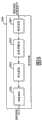
图1是表示本发明的实施方式1的多载波传送方式的发送装置及接收装置的结构的框图。 FIG. 1 is a block diagram showing configurations of a transmission device and a reception device of a multicarrier transmission scheme according to
图2是表示本发明的实施方式1的抵消滤波器部的结构例的框图。 2 is a block diagram showing a configuration example of a cancellation filter unit according to
图3是表示本发明的实施方式1的、(a)将调制向量排列在子载波的频率轴上时的该调制向量的配置状态、以及(b)调制向量及抵消解调滤波处理后的解调向量的各信号点配置(复平面上)的图。 3 shows (a) the arrangement state of the modulation vectors when the modulation vectors are arranged on the frequency axis of the subcarriers, and (b) the modulation vector and the solution after the cancellation demodulation filtering process according to
图4是表示本发明的实施方式1的预编码部的结构例的框图。 FIG. 4 is a block diagram showing a configuration example of a precoding unit according to
图5是表示本发明的实施方式1的多载体调制部的结构例的框图。 5 is a block diagram showing a configuration example of a multicarrier modulation unit according to
图6是表示本发明的实施方式1的多载体解调部的结构例的框图。 6 is a block diagram showing a configuration example of a multi-carrier demodulation unit according to
图7是表示本发明的实施方式1的预编码部的运算及抵消滤波器部的运算的图。 7 is a diagram showing calculations of a precoding unit and calculations of a cancellation filter unit according to
图8是表示本发明的实施方式2的多载波传送方式的接收装置的结构的框图。 FIG. 8 is a block diagram showing the configuration of a reception device of a multi-carrier transmission scheme according to Embodiment 2 of the present invention. the
图9是表示本发明的实施方式3的多载波传送方式的接收装置的结构的一部分的框图。 FIG. 9 is a block diagram showing part of the configuration of a reception device of a multicarrier transmission scheme according to Embodiment 3 of the present invention. the
图10是表示本发明的实施方式4的多载波传送方式的接收装置的结构的一部分的框图。 FIG. 10 is a block diagram showing part of the configuration of a reception device of a multicarrier transmission scheme according to Embodiment 4 of the present invention. the
图11是表示使用自抵消法的以往的OFDM传送方式的发送装置及接收装置的结构的框图。 FIG. 11 is a block diagram showing the configurations of a conventional OFDM transmission system using a self-cancellation method and a transmitting device and a receiving device. the
图12是表示使用自抵消法的以往的OFDM传送方式的、(a)将调制向量排列在子载波的频率轴上时的该调制向量的配置状态、以及(b)调制向量及抵消解调后的解调向量的各信号点配置(复平面上)的图。 12 shows (a) the arrangement state of the modulation vectors when the modulation vectors are arranged on the frequency axis of the subcarriers, and (b) the modulation vectors and the modulation vectors after cancellation demodulation in the conventional OFDM transmission system using the self-cancellation method. The diagram of each signal point configuration (on the complex plane) of the demodulation vector. the
图13是表示使用自抵消法的以往的OFDM传送方式的电力-时间响应的图。 Fig. 13 is a diagram showing a power-time response of a conventional OFDM transmission method using a self-cancellation method. the
图14是表示在使用自抵消法的以往的OFDM传送方式中不使调制向量的极性反转的情况下的、(a)将调制向量排列在子载波的频率轴上时的该调制向量的配置状态、以及(b)调制向量及抵消解调后的解调向量的各信号点配置(复平面上)的图。 FIG. 14 shows the modulation vector when (a) the modulation vector is arranged on the frequency axis of subcarriers in the case where the polarity of the modulation vector is not inverted in the conventional OFDM transmission method using the self-cancellation method. Arrangement state, and (b) diagram of each signal point arrangement (on the complex plane) of the modulation vector and the demodulation vector after cancellation demodulation. the
附图标记说明 Explanation of reference signs
201发送装置 201 sending device
202、2020接收装置 202, 2020 receiving device
211预编码部 211 Precoding Department
212向量调制部 212 vector modulation department
213多载波调制部 213 multi-carrier modulation department
222多载波解调部 222 multi-carrier demodulation department
223抵消滤波器部 223 offset filter part
224向量解调部 224 vector demodulation department
225网格解码部 225 grid decoding department
226变动量推算部 226 Variation Calculation Department
227移动速度测量部 227 Moving Speed Measurement Department
具体实施方式Detailed ways
以下,参照附图对本发明的实施方式进行说明。 Hereinafter, embodiments of the present invention will be described with reference to the drawings. the
(实施方式1) (implementation mode 1)
图1是表示本发明的实施方式1的基于多载波传送方式的发送装置及接收装置的结构的框图。 FIG. 1 is a block diagram showing configurations of a transmission device and a reception device based on a multicarrier transmission scheme according to
发送装置201输入发送数据,并根据输入的发送数据实施多载波调 制,生成多载波信号并输出。从发送装置201送出的多载波信号经由传送路径203被传送给接收装置202。接收装置202将经由传送路径203接收到的多载波信号进行解调,输出接收数据。
发送装置201具备预编码部211、向量调制部212、多载波调制部213、以及频率变换部214。以下说明发送装置201的各部的动作,但为了简洁地说明本发明的主旨,对多载波传送中的每1个符号的动作进行说明。 The
对每1个符号,将K位的发送数据输入到发送装置201中。输入到发送装置201中的发送数据被供给到预编码部211。 K-bit transmission data is input to the
预编码部211中的预编码处理是用于使接收装置102的向量解调部224能够根据解调向量容易判断解调数据的处理。 The precoding process in the
预编码部211输入K位的发送数据,将输入的K位的发送数据分割为N个组。通过该分割处理生成临时的调制信息。预编码部211对各组具有的(K/N)位的发送数据即临时的调制信息实施后述的预编码处理,生成并输出N个调制信息。这里,预编码部211进行与接收装置202的抵消滤波器部223的处理对应的预编码处理。K、N是比0大的整数。在说明本实施方式1时,由于即使将K设为N的倍数也不会发生问题,所以在以后的说明中设K是N的倍数。 The
向量调制部212输入预编码部211输出的N个预编码的调制信息。向量调制部212基于输入的调制信息生成调制向量,输出该N个调制向量。 The
多载波调制部213输入向量调制部212输出的N个调制向量。多载波调制部213利用其N个调制向量对N个子载波分别实施调制,生成基带的多载波调制信号并输出。 The
频率变换部214输入多载波调制部213输出的基带的多载波调制信号。频率变换部214将所输入的基带的多载波调制信号频率变换为规定的无线频率带,将频率变换后的信号作为多载波调制信号输出。频率变换部214输出的多载波调制信号作为发送装置201输出的多载波调制信号,经由空中线路供给到传送路径203。 The
经过了传送路径203的上述多载波调制信号经由空中线路被供给到接收装置202中。 The multi-carrier modulated signal passed through the
接收装置202具备频率变换部221、多载波解调部222、抵消滤波器部223、以及向量解调部224。以下对接收装置202的各部的动作进行说明。为了简洁地说明本发明的主旨,对多载波传送中的每1符号的动作进行说明。 The receiving
接收装置202经由传送路径203接收到的多载波调制信号被供给到频率变换部221。 The multi-carrier modulated signal received by the receiving
频率变换部221输入接收装置202接收到的多载波调制信号。频率变换部221将所输入的多载波调制信号频率变换为基带频带的信号,并将频率变换后的信号作为基带的多载波调制信号输出。 The
多载波解调部222输入频率变换部221输出的基带的多载波调制信号。多载波解调部222将对应于N个子载波的多载波调制信号分别解调,生成N个解调向量并输出。 The
抵消滤波器部223输入多载波解调部222输出的N个调制向量。详细在后面叙述,但抵消滤波器部223对分别对应于相邻的子载波的解调向量分别实施滤波处理,由此生成N个滤波后的解调向量并输出。 The
向量解调部224输入抵消滤波器部223输出的N个滤波后的解调向量。向量解调部224根据该滤波后的解调向量判断K位的解调数据并输出。 The
向量解调部224输出的K位的解调数据被从接收装置102作为解调数据输出。 The K-bit demodulated data output from the
图2是表示本发明的实施方式1的接收装置102的抵消滤波器部223的结构例的框图。图3(a)是表示本发明的实施方式1的将调制向量排列在子载波的频率轴上时的该调制向量的配置状态的图。图3(b)是表示实施方式1的调制向量及抵消解调滤波处理后的解调向量的各信号点配置(复平面上)的图。另外,在图3(b)中,×标记用信号点表示从向量调制部212输出的调制向量的一例。●标记用信号点表示从抵消滤 波器部223输出的滤波处理后的解调向量的一例。 FIG. 2 is a block diagram showing a configuration example of the
图2所示的抵消滤波器部223从多载波解调部222依次输入N个解调向量。抵消滤波器部223以1对1的关系使N个子载波对应于输入的N个解调向量(参照图3)。另外,利用调制向量将子载波进行多载波调制的处理是由多载波调制部213进行。在图3(a)所示的例子中,使调制向量的朝向全部统一为一个方向,但这是为了方便,只要对应于发送数据而信号点(参照图3(b))的位置不同,调制向量的朝向也不同。对于N个子载波,按照其频率轴方向的配置顺序赋予从1号到N号的号码。N个解调向量依次用Y1、Y2、……、YN表示。抵消滤波器部223为了滤波而使用滤波式P(D)=(1-D)(L-1)(L是2以上的整数)。如果将P(D)=(1-D)(L-1)展开,则能够得到多项式P(D)=P0+P1D+P2D2+……+P(L-1) D(L-1)。抵消滤波器部223利用以下的式(1)求出N个滤波后的解调向量Y′1、Y′2、……、Y′N。抵消滤波器部223将求出的解调向量依次输出。 The
式(1)(对应于权利要求书所述的式(2)) Formula (1) (corresponding to the formula (2) described in the claims)
抵消滤波器部223可以作为FIR(Finite Impulse Response,即有限长冲激响应滤波器)型滤波器构成。例如,如果在上述滤波式P(D)=(1-D)(L-1)中设滤波长L为2,则变为P(D)=(1-D)。即,在P(D)的展开式中,P0=1,P1=-1。在此情况下,抵消滤波器部223可以如图2所示那样构成。如图2所示,抵消滤波器部223包括延迟器301、系数赋予器302及303、和加法器304。抵消滤波器部223从多载波解调部222依次输入N个解调向量Yi。延迟器301使依次输入的解调向量Yi延迟1个样本的量并输出。延迟器301在被输入解调向量Yi的时刻,输出1个样本前的解调向量Yi-1。对于输入的解调向量Yi,由系数赋予器302乘以滤波器系数“1”。该系数是基于[P0=1]设定的。对于延迟器301输出的 解调向量Yi-1,由系数赋予器303乘以滤波器系数“-1”。该系数是基于[P1=-1]设定的。在加法器304中,求出由系数赋予器302和系数赋予器303分别乘以系数后的解调向量的和。由此,依次求出滤波后的解调向量Y′i。抵消滤波器部223依次输出滤波后的解调向量Y′i。 The
如在背景技术栏中叙述,在第i个子载波和第k个子载波之间发生的载波间干扰、和在第(i+1)个子载波和第k个子载波之间发生的载波间干扰的和实质上为零,这些载波间干扰相互抵消。由此,在抵消滤波器部223滤波后的解调向量Y′i的干扰成分实质上为零。即,相邻的子载波分别给其他子载波带来的载波间干扰通过基于多项式P(D)的滤波作用而相互抵消。因而,因频率变动、振幅变动或相位变动等产生的载波间干扰,在抵消滤波器部223中能够减轻。此外,实施方式1中,由于将N个调制向量分别分配给N个子载波,所以调制向量与子载波1对1地对应。由此,与上述以往技术不同,传送效率不会降低。 As described in the background technology column, the sum of the intercarrier interference occurring between the ith subcarrier and the kth subcarrier, and the intercarrier interference occurring between the (i+1)th subcarrier and the kth subcarrier Essentially zero, these intercarrier interferences cancel each other out. Accordingly, the interference component of the demodulation vector Y′i filtered by the canceling
图4是表示本发明的实施方式1的发送装置201的预编码部211的结构例的框图。预编码部211可以将抵消滤波器部223看作部分响应滤波器而如非专利文献2所述那样构成。预编码部211是在向量解调部224根据抵消滤波器部223输出的滤波后的解调向量判断解调数据时、用来使该判断变得容易的部件。预编码部211对应于抵消滤波器部223中的处理而将发送数据进行预编码。以下,详细说明预编码部211的结构及动作。 4 is a block diagram showing a configuration example of the
预编码部211首先将输入的K位的发送数据分割为N个组,生成临时的调制信息X1、X2、……、XN。预编码部211按照以下的式(2)进行临时的调制信息X1、X2、……、XN的编码。由此,预编码部211生成N个调制信息X′1、X′2、……、X′N,并输出。 The
式(2)(对应于权利要求书所述的式(1) Formula (2) (corresponding to formula (1) described in claims
例如,在设抵消滤波器部223的滤波器长L为2,滤波式P(D)=(1-D)的情况下,对应于抵消滤波器部223的预编码部211可以如图4所示那样构成。如图4所示,预编码部211包括分割器401、加法器402、剩余器403、和延迟器404。分割器401输入预编码部211输入的K位的发送数据。分割器401将输入的发送数据分割为N个组而生成临时的调制信息X1、X2、……、XN,并依次输出。临时的调制信息可以表示为Xi(1≤i≤N,i是整数)。延迟器404输入预编码部211依次输出的预编码的调制信息X′i,并将输入的信息延迟1个样本而输出。1个样本前的调制信息表示为X′i-1。加法器402求出分割器401输出的临时的调制信息Xi与从延迟器404输出的1个样本前的预编码的调制信息X′i-1的和。剩余器403求出将加法器402输出的加法结果用多值数M(M是2以上的整数)除后的剩余。剩余器403将求出的剩余作为预编码后的调制信息X′i输出。 For example, in the case where the filter length L of the canceling
在向量调制部212的调制规则中使用M值PAM(Pulse AmplitudeModulation)等的振幅调制的情况下,将临时的调制信息Xi及预编码的调制信息X′i用M个实数值表示。剩余器403求出将M个实数值分别用M除后的剩余。另外,在M为2的情况下,调制规则为2值PAM,与BPSK(Binary Phase Shift Keying,即二相移相键控)等价。 When amplitude modulation such as M-value PAM (Pulse Amplitude Modulation) is used as the modulation rule of the
在向量调制部212的调制规则中使用M值QAM(QuadratureAmplitude Modulation,即正交幅度调制)等正交振幅调制的情况下,将临时的调制信息Xi及预编码的调制信息X′i用具有m个实数部和m个虚数部的值的m2个复数值表示。另外,M=m2。剩余器403求出将实数部的值及虚数部的值分别用m除后的剩余。另外,在m为2(即M为4)的情况下,调制规则为4值QAM,与QPSK(Quadrature Phase ShiftKeying,即正交相位偏移键控)等价。 In the case where quadrature amplitude modulation such as M-value QAM (Quadrature Amplitude Modulation, Quadrature Amplitude Modulation) is used in the modulation rule of the
这里,在预编码部211按照上述式(2)依次求出N个调制信息X′ 1、X′2、……、X′N时,最先求出调制信息X′1。为了求出调制信息X′1,作为延迟器404输出的值而预先需要(L-1)个调制信息X′2-L 、……、X′0。所以,假设对调制信息X′2-L、……、X′0预先赋予已知的值。预编码部211只要将这些调制信息X′2-L、……、X′0先于调制信息X′1、X′2、……、X′N输入保持并送出就可以。例如,在假设L=2的情况下的图4所示的预编码部211中,在求出N个调制信息X′1、X′2、……、X′N时,作为延迟器404输出的值而预先需要1个调制信息X′0。即,需要在与分割器401输出临时的调制信息X1时,同时由延迟器404输出调制信息X′0。在此情况下,只要将调制信息X0′作为已知的值预先保持在延迟器404中,并且与分割器401输出临时的调制信息X1同步地从延迟器404输出调制信息X′0就可以。 Here, when the
此外,在由抵消滤波器部223按照式(1)求出N个滤波后的解调向量Y′1、Y′2、……、Y′N时,最先求出滤波的解调向量Y′1。为了求出解调向量Y′1,作为延迟器301输出的值而预先需要(L-1)个解调向量Y2-L、……、Y0。所以,只要抵消滤波器部223预先输入与预编码部211输出的已知的上述(L-1)个调制信息X′2-L、……、X′0对应的解调向量Y2-L、……、Y0就可以。接收装置202从发送装置201预先接收解调向量Y2-L、……、Y0,抵消滤波器部223输入该接收到的解调向量。例如,在假设L=2的情况下的图2所示的抵消滤波器部223中,在求出N个滤波后的解调向量Y′1、Y′2、……、Y′N时,作为延迟器301输出的值而预先需要解调向量Y0。即,需要在与抵消滤波器部223输入解调向量Y1时,同时由延迟器301输出解调向量Y0。在此情况下,只要直到对抵消滤波器部223输入解调向量Y1,将解调向量Y0先接收并输入到延迟器301中就可以。 In addition, when the N filtered demodulation vectors Y′1 , Y′2 , . '1 . In order to obtain the demodulation vector Y'1 , (L-1) demodulation vectors Y2-L , ..., Y0 are required in advance as values output from the
根据以上的结构,发送装置201的预编码部211将发送数据分割为N个组,并对分割后的数据实施预编码处理而生成N个调制信息。向量调制部212由N个调制信息生成N个调制向量。多载波调制部213利用N个调制向量,将N个子载波分别进行多载波调制。由此,由于N个子载波都能够分别独立地承载发送数据,所以传送效率不会降低。此外,接收装置202的抵消滤波器部223根据相邻的子载波间的载波间干扰特性 实施滤波处理,抵消载波间干扰。由此,能够减轻因频率变动、振幅变动或者相位变动等而发生的载波间干扰。此外,在发送装置201中,不进行如以往那样将子载波每两个分组、使对各组分配的调制向量的极性在相邻的子载波间反转的处理。由此,从多载波调制部213输出的多载波调制信号的时间响应波形如图13上侧所示那样变得比较平坦。不会发生如上述以往技术那样高输出的信号集中在符号中央部的时间、符号中央部的信号振幅变大的不良状况。因而,不用提高发送装置201的高频电力放大器的最大输出电力就可以。此外,如后述的实施例所示,即使进行抵消处理而信号点数增加,通过在发送侧进行预编码处理,也能够在接收侧将原来的发送数据唯一地复原。 According to the above configuration, the
另外,在本实施方式中,作为多载波传送方式的一例,可以举出OFDM(Orthogonal Frequency Division Multiplexing,正交分频复用)传送方式。在使用OFDM传送方式的情况下,多载波调制部213及多载波解调部222可以分别如图5及图6所示那样构成。 In addition, in this embodiment, an OFDM (Orthogonal Frequency Division Multiplexing, Orthogonal Frequency Division Multiplexing) transmission method can be mentioned as an example of a multi-carrier transmission method. When the OFDM transmission method is used, the
如图5所示,多载波调制部213包括IDFT部231和保护间隔附加部232。IDFT部231输入对多载波调制部213输入的N个调制向量,对输入的调制向量实施逆傅立叶变换而生成基带频带的OFDM信号并输出。保护间隔附加部232输入IDFT部231输出的基带频带的OFDM信号,对输入的基带频带的OFDM信号附加周期扩展的保护间隔信号。保护间隔附加部232将附加了保护间隔的信号的基带频带的多载波调制信号从多载波调制部213输出。 As shown in FIG. 5 , the
如图6所示,多载波解调部222包括保护间隔除去部241和DFT部242。保护间隔除去部241从多载波解调部222输入的基带频带的多载波调制信号中除去保护间隔的信号并输出。DFT部242将保护间隔除去部241输出的信号进行傅立叶变换而求出N个解调向量。接着,DFT部242从多载波解调部222输出N个解调向量。 As shown in FIG. 6 , the
(实施例) (Example)
以下,介绍关于实施方式1的实施例。参照图2、图3、图4及图7 说明预编码部211及抵消滤波器部223的作用。图7是将由预编码部211进行的运算处理、和由抵消滤波器部223进行的运算处理并列表示的图。在该例中,假设多载波调制方式的多值数M为4的情况。具体的调制方式并没有特别限定,但例如可以使用QAM。设抵消滤波器部223的滤波器长L为2、滤波器的多项式P(D)=(1-D)。图7表示求出第i个调制信息X′i及第i个解调向量Y′i的运算的全部的组合。在图7中,各个列从左端列开始依次表示X1、X′i-1、X′i、Yi、Yi-1、Y′i。 Hereinafter, examples related to the first embodiment will be described. The functions of the
在图4中,输入到预编码部211中的发送数据首先被输入到分割器401中。分割器401将输入的发送数据每两位进行分割,将分割后的两位分配给1个符号。通过将发送数据每两位进行分割,发送数据被编码为4个值。由此,发送数据被变换为具有[0,1,2,3]的4个值(即多值数4)的临时调制信息X1,从分割器401输出。加法器402将第i个临时调制信息X1与保持在延迟器404中的第(i-1)个调制信息X′i-1相加。第(i-1)个调制信息X′i-1也具有[0,1,2,3]的4个值。其相加值被输入到剩余器403中。剩余器403将输入的相加值用多值数4除而求出余数。由剩余器403求出的余数作为第i个调制信息X′i被从预编码部211输出。这里,由于第i个调制信息Xi′是在剩余器403中用多值数4除后的余数,所以如图11所示,具有[0,1,2,3]的4个值。即,由第i个临时的调制信息Xi 和第(i-1)个调制信息X′i-1得到第i个调制信息X′i。得到的调制信息X′i在向量调制部212中被变换为复平面上的调制向量。得到的调制向量在多载波调制部213中用于子载波的多载波调制。得到的多载波调制信号在频率变换部214中被频率变换为适合于无线通信的频率带的信号,被从发送装置201送出。 In FIG. 4 , transmission data input to
被从发送装置201送出的多载波调制信号被接收装置202接收。在接收装置202中,多载波调制信号在频率变换部221中被变换为基带频带的多载波调制信号。基带频带的多载波调制信号在多载波解调部222中被解调。解调后的信号在抵消滤波器部223中被滤波处理。在图2中,在对抵消滤波器部223输入第i个解调向量Yi时,在延迟器301中已经 保持有第(i-1)个解调向量Yi-1。在系数赋予器302对第i个解调向量Yi乘以滤波器系数“1”,在系数赋予器303对第(i-1)个解调向量Yi-1 乘以滤波器系数“-1”。分别乘以各滤波器系数后的Yi和Yi-1在加法器304中被相加。由加法器304得到的相加结果作为第i个滤波后的解调向量Y′i被从抵消滤波器部223输出。即,第i个滤波后的解调向量Y′i 是从第i个解调向量Yi减去第(i-1)个解调向量Yi-1得到的。这意味着进行分别对应于相邻的子载波的两个解调向量彼此的减法。 The multi-carrier modulation signal sent from the transmitting
假设在发送装置201与接收装置202之间的传送中除了载波间干扰以外没有传送错误。即,假设第i个解调向量Yi等于第i个调制信息X′i、第(i-1)个解调向量Yi-1等于第(i-1)个调制信息X′i-1。在此情况下,第i个滤波后的解调向量Y′i成为图7的右端列所示的值。滤波后的解调向量Y′i是抵消滤波器部223的输出。由图7可知,在第i个滤波后的解调向量Y′i为“0”的情况下,如左端列所示,作为第i个临时的调制信息Xi而发送“0”。同样可知在Y′i为“1”或“-3”的情况下,作为Xi而发送“1”。可知在Y′i为“2”或“-2”的情况下,作为Xi而发送“2”。可知在Y′i为“3”或“-1”的情况下,作为Xi而发送“3”。即,只要观测第i个滤波后的解调向量Y′i,就能够唯一地推测发送来的第i个临时的调制信息Xi。只要唯一地求出临时的调制信息Xi,就能够求出对应于该临时的调制信息Xi的发送数据。因而,在实施方式1中,如图3(b)所示,即使在抵消解调之后信号点的数量增加,在向量解调部224中也能够容易且唯一地复原发送数据。 It is assumed that there is no transmission error other than inter-carrier interference in the transmission between the
在抵消滤波器部223的处理中,基于第(i-1)个解调向量Yi-1求出第i个滤波后的解调向量Y′i。在本实施例中,通过预编码部211的作用,不论第(i-1)个解调向量Yi-1即第(i-1)个调制信息X′i-1是怎样的值,都能够根据第i个滤波后的解调向量Yi唯一地推算第i个临时的调制信息Xi。根据以上的说明可知,通过在发送装置中进行预编码处理,即使不像上述以往技术那样将子载波每L个分组、在构成各组的相邻的子载波间唯一地决定调制向量的关系,也能够在接收侧正确复原发送数 据。由此,实施方式1不会如上述以往技术那样的信号的传送效率变为1/L而传送效率降低。 In the processing of the canceling
(实施方式2) (implementation mode 2)
图8是表示本发明的实施方式2的多载波传送方式的接收装置的结构的框图。 FIG. 8 is a block diagram showing the configuration of a reception device of a multi-carrier transmission scheme according to Embodiment 2 of the present invention. the
如图8所示,接收装置2020包括频率变换部221、多载波解调部222、抵消滤波器部223和网格解码部225。接收装置2020是将实施方式1的接收装置202(参照图1)的向量解调部224替换为网格解码部225的结构,对于其他结构可以设为相同。在以下的说明中,对于与实施方式1相同的结构,赋予相同的附图标记而省略其说明。 As shown in FIG. 8 , the
网格解码部225输入抵消滤波器部223输出的N个滤波后的解调向量。网格解码部225进行滤波后的解调向量的网格解码而生成K个解调数据并输出。从网格解码部225输出的K个解调数据被从接收装置2020输出。 The
网格解码部225根据以抵消滤波器部223的延迟器301保持的(L-1)个解调向量为状态变量的网格迁移,由输入的解调向量求出最确切的迁移。网格解码部225将产生该最确切的迁移的数据作为解调数据得到。网格解码部225可以通过使用例如维特比算法(非专利文献3)、BCJR算法(非专利文献4)、MAP(最大后验概率)解码等构成。 The
根据该接收装置2020,由抵消滤波器部223实施滤波处理,由网格解码部225将抵消滤波器部223的状态迁移进行解码。由此,接收装置2020不会使信号的传送效率劣化,能够降低因频率变动、振幅变动、或者相位变动等产生的载波间干扰,正确地复原发送数据。此外,在发送装置201中不像以往那样进行使将相邻的两个子载波分别调制的调制向量的极性相互反转的处理。由此,从多载波调制部213输出的多载波调制信号的时间响应波形变得比较平坦。因而,可以不提高发送装置201的高频电力放大器的最大输出电力。 According to this
另外,在接收装置2020中使用网格解码部225的情况下,也可以不用发送装置201进行预编码处理。在此情况下,只要代替预编码部211设置分割器401就可以。代替预编码部211设置分割器401作为OFDM传送用的一般的发送装置已经存在。由此,可以代替有关本实施方式的发送装置201而使用一般的发送装置。由此,即使使用该一般的发送装置,也能够发挥实施方式1的上述良好的效果。实施方式2在如广播用发送装置等那样对于设置预编码部211有限制的情况下是特别有效的。 In addition, when the
(实施方式3) (implementation mode 3)
图9是表示本发明的实施方式3的多载波传送方式的接收装置的结构的一部分的框图。 FIG. 9 is a block diagram showing part of the configuration of a reception device of a multicarrier transmission scheme according to Embodiment 3 of the present invention. the
实施方式3的接收装置(未图示)如图9所示,在抵消滤波器部223的系数赋予部302、303上连结有变动量推算部226,这一点与实施方式1不同,其他结构与实施方式1相同。对于与实施方式1相同的结构赋予相同的标记,省略其说明。变动量推算部226推算频率变动、振幅变动、或者相位变动等变动量。变动量推算部226例如根据多载波调制信号中附加的已知的导频信号推算传输路径响应,根据该传输路径响应的时间变动推算频率波动、振幅变动或相位变动等变动量。基于由变动量推算部226推算的变动量,抵消滤波器部223能够控制该系数赋予器302、303的系数。 The receiving device (not shown) of Embodiment 3 differs from
通过基于由变动量推算部226推算的变动量控制该系数赋予器302、303的系数,能够修正通过频率变动、相位变动、或者振幅变动等的变动产生的传送路径响应等的偏差,进一步降低变动的影响。 By controlling the coefficients of the
(实施方式4) (Implementation 4)
图10是表示本发明的实施方式4的多载波传送方式的接收装置的结构的一部分的框图。实施方式4的接收装置(未图示)如图10所示,在抵消滤波器部223的系数赋予部302、303上连结有移动速度测量部227, 这一点与实施方式1不同,其他结构与实施方式1相同。对于与实施方式1相同的结构赋予相同的标记,省略其说明。移动速度测量部227是假设例如接收装置202设置在汽车等的移动体上、或者接收装置202被人搬运的情况而设置的。移动速度测量部227的移动速度测量机构并没有特别限定,例如可以使用车速脉冲发生器等移动体的速度脉冲发生器来检测接收装置202的移动速度。或者,移动速度测量部227也可以利用GPS等位置测量技术,以规定的时间间隔测量移动体的当前位置,根据在该规定的时间移动的距离来计算移动速度。 FIG. 10 is a block diagram showing part of the configuration of a reception device of a multicarrier transmission scheme according to Embodiment 4 of the present invention. The receiving device (not shown) of Embodiment 4 differs from
一般,起因于多普勒现象的载波间干扰与发送装置或接收装置的移动速度的相关性较高。由此,通过基于由移动速度测量部227得到的接收装置202的移动速度信息控制抵消滤波器部223的系数赋予器302、303的系数,特别是能够进一步减轻频率变动的影响。 Generally, inter-carrier interference caused by the Doppler phenomenon has a high correlation with the moving speed of the transmitting device or the receiving device. Accordingly, by controlling the coefficients of the
另外,以上所述的所有实施方式可以作为集成电路即LSI实现。各实施方式既可以单独单芯片化,或者也可以包括所有实施方式而单芯片化。 In addition, all the embodiments described above can be realized as an integrated circuit, that is, an LSI. Each embodiment may be formed into a single chip alone, or may be formed into a single chip including all the embodiments. the
另外,上述LSI根据集成度的差异,包括IC、系统LSI、超级LSI、超大规模LSI等的各种LSI。 In addition, the above-mentioned LSIs include various LSIs such as ICs, system LSIs, super LSIs, and ultra-large-scale LSIs, depending on the degree of integration. the
此外,各实施方式的集成电路化的方法并不限于LSI,也可以由专用电路或通用处理器实现。或者,也可以利用在LSI制造后可编程的FPGA(Field Programmable Gate Array,即现场可编程门阵列)、或能够重构LSI内部的电路单元的连接或设定的可重构处理器。 In addition, the method of circuit integration in each embodiment is not limited to LSI, and may be realized by a dedicated circuit or a general-purpose processor. Alternatively, an FPGA (Field Programmable Gate Array, Field Programmable Gate Array) that can be programmed after the LSI is manufactured, or a reconfigurable processor that can reconfigure the connection or settings of the circuit units inside the LSI can also be used. the
进而,如果因半导体技术的进步或派生的其他技术而出现替换LSI的集成电路化的技术,当然也可以利用该技术进行功能块的集成化。有可能是生物技术的应用。 Furthermore, if an integrated circuit technology to replace LSI appears due to progress in semiconductor technology or other derived technologies, it is of course possible to integrate functional blocks using this technology. There may be applications of biotechnology. the
工业实用性 Industrial applicability
有关本发明的多载波传送方式的发送装置及接收装置能够减轻因多普勒现象带来的频率变动等而发生的载波间干扰,在移动体通信等中是具有实用性的。 The transmitting device and receiving device of the multi-carrier transmission method according to the present invention can reduce inter-carrier interference caused by frequency variation due to Doppler phenomenon, etc., and are practical in mobile communication and the like. the
Claims (19)
Translated fromChineseApplications Claiming Priority (3)
| Application Number | Priority Date | Filing Date | Title |
|---|---|---|---|
| JP2005181939 | 2005-06-22 | ||
| JP181939/2005 | 2005-06-22 | ||
| PCT/JP2006/312280WO2006137375A1 (en) | 2005-06-22 | 2006-06-20 | Transmitting apparatus and receiving apparatus of multicarrier transmission system, and transmitting method and receiving method using multicarrier transmission system |
Publications (2)
| Publication Number | Publication Date |
|---|---|
| CN101204032A CN101204032A (en) | 2008-06-18 |
| CN101204032Btrue CN101204032B (en) | 2013-04-10 |
Family
ID=37570404
Family Applications (1)
| Application Number | Title | Priority Date | Filing Date |
|---|---|---|---|
| CN2006800224580AExpired - Fee RelatedCN101204032B (en) | 2005-06-22 | 2006-06-20 | Transmitting apparatus and receiving apparatus of multicarrier transmission system, and transmitting method and receiving method using multicarrier transmission system |
Country Status (5)
| Country | Link |
|---|---|
| US (2) | US8090034B2 (en) |
| EP (1) | EP1876742A4 (en) |
| JP (1) | JP4898674B2 (en) |
| CN (1) | CN101204032B (en) |
| WO (1) | WO2006137375A1 (en) |
Families Citing this family (20)
| Publication number | Priority date | Publication date | Assignee | Title |
|---|---|---|---|---|
| WO2010021575A1 (en)* | 2008-08-20 | 2010-02-25 | Telefonaktiebolaget L M Ericsson (Publ) | Precoder for a communication system and methods used in said communication system |
| FR2937482B1 (en)* | 2008-10-21 | 2011-12-30 | St Microelectronics Sa | RECEIVER COMPRISING A DEVICE FOR CORRECTING THE DOPPLER EFFECT |
| CN101998594B (en)* | 2009-08-08 | 2014-04-30 | 中兴通讯股份有限公司 | Method and device for reducing mutual interference of multiple carriers |
| CN102006144B (en) | 2009-09-01 | 2014-01-08 | 华为技术有限公司 | Precoding method and device, frequency domain equalization method and device |
| JP5212316B2 (en)* | 2009-09-03 | 2013-06-19 | 富士通株式会社 | Wireless communication apparatus and wireless communication method |
| JP5578619B2 (en) | 2010-12-10 | 2014-08-27 | パナソニック インテレクチュアル プロパティ コーポレーション オブ アメリカ | Transmitter and receiver |
| JP5559759B2 (en)* | 2011-09-12 | 2014-07-23 | 日本電信電話株式会社 | Wireless communication system and wireless communication method |
| CN105933909A (en)* | 2012-02-24 | 2016-09-07 | 华为技术有限公司 | Physical cell ID configuration, logic root sequence index configuration method and base station device |
| JP5892599B2 (en)* | 2012-04-16 | 2016-03-23 | 国立大学法人東京工業大学 | OFDM (Orthogonal Frequency Division Multiplexing) demodulator, OFDM transmission system, and OFDM demodulation method |
| US8737458B2 (en) | 2012-06-20 | 2014-05-27 | MagnaCom Ltd. | Highly-spectrally-efficient reception using orthogonal frequency division multiplexing |
| US9219631B2 (en) | 2012-09-21 | 2015-12-22 | Kratos Integral Holdings, Llc | System and method for increasing spot beam satellite bandwidth |
| US9130624B2 (en)* | 2012-09-21 | 2015-09-08 | Kratos Integral Holdings, Llc | Envelope feedback interference reduction and data throughput maximization |
| US10135518B2 (en)* | 2012-11-15 | 2018-11-20 | Novelsat Ltd. | Echo cancellation in communication transceivers |
| WO2014139148A1 (en)* | 2013-03-15 | 2014-09-18 | 华为技术有限公司 | Method and terminal device for adjusting parameters of sending device and receiving device |
| CN104658545B (en)* | 2013-11-25 | 2018-04-24 | 宏碁股份有限公司 | Voice data transmission system and voice data transmission method |
| US9496900B2 (en) | 2014-05-06 | 2016-11-15 | MagnaCom Ltd. | Signal acquisition in a multimode environment |
| TWI568210B (en)* | 2015-10-08 | 2017-01-21 | 財團法人工業技術研究院 | Interference mitigation method and network server using the same |
| US9967021B2 (en) | 2016-07-14 | 2018-05-08 | Suntrust Bank | Systems and methods for signal cancellation in satellite communication |
| US10200071B1 (en)* | 2017-08-07 | 2019-02-05 | Kratos Integral Holdings, Llc | System and method for interference reduction in radio communications |
| CN115412411B (en)* | 2021-05-26 | 2024-05-03 | 华为技术有限公司 | Data transmission method and device |
Citations (2)
| Publication number | Priority date | Publication date | Assignee | Title |
|---|---|---|---|---|
| JP2003188847A (en)* | 2001-09-27 | 2003-07-04 | Toyota Central Res & Dev Lab Inc | Multicarrier demodulation method and multicarrier demodulation device |
| CN1781276A (en)* | 2003-02-27 | 2006-05-31 | 英特尔公司 | Apparatus and associated methods to introduce diversity in a multicarrier communication channel |
Family Cites Families (7)
| Publication number | Priority date | Publication date | Assignee | Title |
|---|---|---|---|---|
| IL125242A0 (en)* | 1998-07-06 | 1999-03-12 | Metalink Ltd | Channel precoder using an infinite impulse response filter |
| FI108265B (en)* | 2000-02-21 | 2001-12-14 | Tellabs Oy | Method and apparatus for performing the learning phase of an adaptive channel correction during a digital telecommunication connection |
| US20020048333A1 (en)* | 2000-05-25 | 2002-04-25 | Nadeem Ahmed | Joint detection in OFDM systems |
| US7298785B2 (en)* | 2001-07-04 | 2007-11-20 | Kabushiki Kaisha Toyota Chuo Kenkyusho | Multicarrier demodulation method and apparatus, and multicarrier modulation method and apparatus |
| EP1461924A4 (en)* | 2001-11-29 | 2010-07-07 | Qualcomm Inc | Method and apparatus for determining the log-likelihood ratio with precoding |
| CN1290280C (en)* | 2002-12-31 | 2006-12-13 | 上海贝尔阿尔卡特股份有限公司 | Method of self eliminating interference between self adaptive carriers and receiving and transmitting machine |
| US7782970B2 (en)* | 2003-02-27 | 2010-08-24 | Intel Corporation | Apparatus and associated methods to introduce diversity in a multicarrier communication channel |
- 2006
- 2006-06-20CNCN2006800224580Apatent/CN101204032B/ennot_activeExpired - Fee Related
- 2006-06-20USUS11/915,444patent/US8090034B2/ennot_activeExpired - Fee Related
- 2006-06-20WOPCT/JP2006/312280patent/WO2006137375A1/ennot_activeCeased
- 2006-06-20EPEP06766941.6Apatent/EP1876742A4/ennot_activeWithdrawn
- 2006-06-20JPJP2007522281Apatent/JP4898674B2/ennot_activeExpired - Fee Related
- 2011
- 2011-11-30USUS13/307,470patent/US8199838B2/ennot_activeExpired - Fee Related
Patent Citations (2)
| Publication number | Priority date | Publication date | Assignee | Title |
|---|---|---|---|---|
| JP2003188847A (en)* | 2001-09-27 | 2003-07-04 | Toyota Central Res & Dev Lab Inc | Multicarrier demodulation method and multicarrier demodulation device |
| CN1781276A (en)* | 2003-02-27 | 2006-05-31 | 英特尔公司 | Apparatus and associated methods to introduce diversity in a multicarrier communication channel |
Also Published As
| Publication number | Publication date |
|---|---|
| US8199838B2 (en) | 2012-06-12 |
| JPWO2006137375A1 (en) | 2009-01-15 |
| US20120076220A1 (en) | 2012-03-29 |
| CN101204032A (en) | 2008-06-18 |
| US8090034B2 (en) | 2012-01-03 |
| EP1876742A4 (en) | 2014-07-16 |
| JP4898674B2 (en) | 2012-03-21 |
| WO2006137375A1 (en) | 2006-12-28 |
| US20090180566A1 (en) | 2009-07-16 |
| EP1876742A1 (en) | 2008-01-09 |
Similar Documents
| Publication | Publication Date | Title |
|---|---|---|
| CN101204032B (en) | Transmitting apparatus and receiving apparatus of multicarrier transmission system, and transmitting method and receiving method using multicarrier transmission system | |
| EP1478149B1 (en) | Multicarrier receiver | |
| CN101471912B (en) | Transmitting device, transmitting/receiving device, transmitting method and transmitting/receiving method | |
| KR100911424B1 (en) | Method and apparatus for determining log-likelihood ratio through precoding | |
| KR100712606B1 (en) | A method of determining a variable quantization step size to improve the performance of channel decoding, a method and apparatus for performing channel decoding based on the variable quantization step size | |
| JP6300992B2 (en) | Transmitter | |
| CN105453462B (en) | Sending device, receiving device and communication system | |
| JP3429746B2 (en) | Echo phase offset correction in multicarrier demodulation systems | |
| Mohammadnia-Avval et al. | Compressive sensing recovery of nonlinearly distorted OFDM signals | |
| KR20060106223A (en) | Apparatus and Method for Transmitting Bit Insertion and Code Modulation in Orthogonal Frequency Division Multiplexing System | |
| Sharma et al. | Performance analysis of UFMC for 5G technologies with different channel coding techniques | |
| JP6743327B2 (en) | Wireless communication system, wireless transmitter, and wireless receiver | |
| Ogundile et al. | Improved reliability information for OFDM systems on time-varying frequency-selective fading channels | |
| Li et al. | Joint iterative receiver design and multi-segmental channel estimation for OFDM systems over rapidly time-varying channels | |
| Bedoui et al. | An mmse integrated equalization for harq chase combining in oqam-fbmc systems | |
| Goyani et al. | A Review-Performance comparison of conventional and wavelet-based OFDM system | |
| JP2013090043A (en) | Receiving device and reception method | |
| Dinis et al. | Joint detection and channel estimation for block transmission schemes | |
| Tören et al. | A novel hybrid OFDM technique for 5G | |
| Butenko et al. | Software Model of a 5G Data Transmission System with Increased Spectral Efficiency | |
| Kang et al. | Fast-varying doppler compensation for underwater acoustic OFDM systems | |
| Hemalatha et al. | Bit Loading of GFDM based Communication System for IoT Applications | |
| Imran et al. | Comparative analysis of channel estimation in SISO and MIMO OFDM using wiener filters under LTE standards | |
| Rao et al. | TURBO coded OFDM performance analysis for digital video broadcasting | |
| Kuriki et al. | Time-domain channel equalization for subcarrier spacing compressed FDM with SC-MMSE turbo equalization receiver |
Legal Events
| Date | Code | Title | Description |
|---|---|---|---|
| C06 | Publication | ||
| PB01 | Publication | ||
| C10 | Entry into substantive examination | ||
| SE01 | Entry into force of request for substantive examination | ||
| C14 | Grant of patent or utility model | ||
| GR01 | Patent grant | ||
| CF01 | Termination of patent right due to non-payment of annual fee | Granted publication date:20130410 | |
| CF01 | Termination of patent right due to non-payment of annual fee |