CN101203281B - Breakaway or folding elliptical exercise machine - Google Patents
Breakaway or folding elliptical exercise machineDownload PDFInfo
- Publication number
- CN101203281B CN101203281BCN2006800218359ACN200680021835ACN101203281BCN 101203281 BCN101203281 BCN 101203281BCN 2006800218359 ACN2006800218359 ACN 2006800218359ACN 200680021835 ACN200680021835 ACN 200680021835ACN 101203281 BCN101203281 BCN 101203281B
- Authority
- CN
- China
- Prior art keywords
- exercise machine
- elliptical exercise
- base support
- elliptical
- pivot
- Prior art date
- Legal status (The legal status is an assumption and is not a legal conclusion. Google has not performed a legal analysis and makes no representation as to the accuracy of the status listed.)
- Expired - Fee Related
Links
- 230000007246mechanismEffects0.000claimsabstractdescription57
- 238000000034methodMethods0.000claimsdescription14
- 238000010276constructionMethods0.000claimsdescription6
- 230000008569processEffects0.000claimsdescription6
- 238000010977unit operationMethods0.000claims1
- 230000033001locomotionEffects0.000description23
- 230000008878couplingEffects0.000description15
- 238000010168coupling processMethods0.000description15
- 238000005859coupling reactionMethods0.000description15
- 230000006870functionEffects0.000description9
- 230000000694effectsEffects0.000description4
- 230000004048modificationEffects0.000description4
- 238000012986modificationMethods0.000description4
- 230000000712assemblyEffects0.000description3
- 238000000429assemblyMethods0.000description3
- 230000000295complement effectEffects0.000description3
- 230000007812deficiencyEffects0.000description2
- 230000005021gaitEffects0.000description2
- 239000000463materialSubstances0.000description2
- 230000004044responseEffects0.000description2
- 230000007704transitionEffects0.000description2
- 230000006978adaptationEffects0.000description1
- 230000004075alterationEffects0.000description1
- 238000005452bendingMethods0.000description1
- 230000000903blocking effectEffects0.000description1
- 230000009194climbingEffects0.000description1
- 230000001143conditioned effectEffects0.000description1
- 230000009977dual effectEffects0.000description1
- 238000012856packingMethods0.000description1
- 230000000284resting effectEffects0.000description1
- 230000000717retained effectEffects0.000description1
- 238000005096rolling processMethods0.000description1
- 230000035939shockEffects0.000description1
- 238000004088simulationMethods0.000description1
Images


Classifications
- A—HUMAN NECESSITIES
- A63—SPORTS; GAMES; AMUSEMENTS
- A63B—APPARATUS FOR PHYSICAL TRAINING, GYMNASTICS, SWIMMING, CLIMBING, OR FENCING; BALL GAMES; TRAINING EQUIPMENT
- A63B22/00—Exercising apparatus specially adapted for conditioning the cardio-vascular system, for training agility or co-ordination of movements
- A63B22/06—Exercising apparatus specially adapted for conditioning the cardio-vascular system, for training agility or co-ordination of movements with support elements performing a rotating cycling movement, i.e. a closed path movement
- A63B22/0664—Exercising apparatus specially adapted for conditioning the cardio-vascular system, for training agility or co-ordination of movements with support elements performing a rotating cycling movement, i.e. a closed path movement performing an elliptic movement
- A—HUMAN NECESSITIES
- A63—SPORTS; GAMES; AMUSEMENTS
- A63B—APPARATUS FOR PHYSICAL TRAINING, GYMNASTICS, SWIMMING, CLIMBING, OR FENCING; BALL GAMES; TRAINING EQUIPMENT
- A63B22/00—Exercising apparatus specially adapted for conditioning the cardio-vascular system, for training agility or co-ordination of movements
- A63B22/0002—Exercising apparatus specially adapted for conditioning the cardio-vascular system, for training agility or co-ordination of movements involving an exercising of arms
- A63B22/001—Exercising apparatus specially adapted for conditioning the cardio-vascular system, for training agility or co-ordination of movements involving an exercising of arms by simultaneously exercising arms and legs, e.g. diagonally in anti-phase
- A—HUMAN NECESSITIES
- A63—SPORTS; GAMES; AMUSEMENTS
- A63B—APPARATUS FOR PHYSICAL TRAINING, GYMNASTICS, SWIMMING, CLIMBING, OR FENCING; BALL GAMES; TRAINING EQUIPMENT
- A63B22/00—Exercising apparatus specially adapted for conditioning the cardio-vascular system, for training agility or co-ordination of movements
- A63B22/06—Exercising apparatus specially adapted for conditioning the cardio-vascular system, for training agility or co-ordination of movements with support elements performing a rotating cycling movement, i.e. a closed path movement
- A63B22/0664—Exercising apparatus specially adapted for conditioning the cardio-vascular system, for training agility or co-ordination of movements with support elements performing a rotating cycling movement, i.e. a closed path movement performing an elliptic movement
- A63B2022/067—Exercising apparatus specially adapted for conditioning the cardio-vascular system, for training agility or co-ordination of movements with support elements performing a rotating cycling movement, i.e. a closed path movement performing an elliptic movement with crank and handles being on opposite sides of the exercising apparatus with respect to the frontal body-plane of the user, e.g. the crank is behind and handles are in front of the user
- A—HUMAN NECESSITIES
- A63—SPORTS; GAMES; AMUSEMENTS
- A63B—APPARATUS FOR PHYSICAL TRAINING, GYMNASTICS, SWIMMING, CLIMBING, OR FENCING; BALL GAMES; TRAINING EQUIPMENT
- A63B22/00—Exercising apparatus specially adapted for conditioning the cardio-vascular system, for training agility or co-ordination of movements
- A63B22/20—Exercising apparatus specially adapted for conditioning the cardio-vascular system, for training agility or co-ordination of movements using rollers, wheels, castors or the like, e.g. gliding means, to be moved over the floor or other surface, e.g. guide tracks, during exercising
- A63B22/201—Exercising apparatus specially adapted for conditioning the cardio-vascular system, for training agility or co-ordination of movements using rollers, wheels, castors or the like, e.g. gliding means, to be moved over the floor or other surface, e.g. guide tracks, during exercising for moving a support element in reciprocating translation, i.e. for sliding back and forth on a guide track
- A63B22/205—Exercising apparatus specially adapted for conditioning the cardio-vascular system, for training agility or co-ordination of movements using rollers, wheels, castors or the like, e.g. gliding means, to be moved over the floor or other surface, e.g. guide tracks, during exercising for moving a support element in reciprocating translation, i.e. for sliding back and forth on a guide track in a substantially vertical plane, e.g. for exercising against gravity
- A—HUMAN NECESSITIES
- A63—SPORTS; GAMES; AMUSEMENTS
- A63B—APPARATUS FOR PHYSICAL TRAINING, GYMNASTICS, SWIMMING, CLIMBING, OR FENCING; BALL GAMES; TRAINING EQUIPMENT
- A63B2210/00—Space saving
- A63B2210/50—Size reducing arrangements for stowing or transport
Landscapes
- Health & Medical Sciences (AREA)
- Cardiology (AREA)
- Vascular Medicine (AREA)
- General Health & Medical Sciences (AREA)
- Physical Education & Sports Medicine (AREA)
- Rehabilitation Tools (AREA)
Abstract
Translated fromChinese
Description
Translated fromChinese技术领域technical field
技术本发明一般地涉及健身设备或健身器。更具体地说,本发明涉及具有一个或多个可折离(breakaway)部件的椭圆或椭圆型健身器,该可折离部件构造成使椭圆健身器能实现用于一个或多个目的的紧凑构造,以减小椭圆健身器占据的空间并提供用于储存和/或运输椭圆健身器的有利构造。TECHNICAL [0002] The present invention generally relates to exercise equipment or exercise machines. More specifically, the present invention relates to elliptical or elliptical-type exercise machines having one or more breakaway components configured to enable the elliptical exerciser to be compacted for one or more purposes. configured to reduce the space occupied by the elliptical exerciser and provide an advantageous configuration for storing and/or transporting the elliptical exerciser.
背景技术Background technique
有构造成供使用机器的人围绕封闭路径经过或行进以模拟跨步、跑步、走路和/或攀登运动的交替往复脚部支承件的健身器是本技术领域已知的,并通常称为椭圆健身器或椭圆型交替训练机。一般而言,椭圆或椭圆型健身器包括一对设计成接纳和支承用户的脚的一对往复脚部支承件。每个往复脚部支承件具有用于围绕枢转点或枢转轴线旋转运动的至少一个被支承的端部,另一个端部支承成引起往复脚部支承件行进或经过封闭路径,诸如往复椭圆形或长圆形路径或其他类似几何轮廓。因此,健身器运行时,使得每个往复脚部支承件行进或经过封闭路径,由此模拟用户的跨步运动以实现健身目的。往复脚部支承件构造成彼此异相180°以模拟适当和自然的交替跨步运动。Exercise machines with alternating reciprocating foot supports configured for a person using the machine to traverse or travel around a closed path to simulate striding, running, walking and/or climbing motions are known in the art and are commonly referred to as ellipticals. Gym machine or elliptical alternating trainer. Generally, an elliptical or elliptical-type exercise machine includes a pair of reciprocating foot supports designed to receive and support a user's feet. Each reciprocating foot support has at least one end supported for rotational movement about a pivot point or axis, the other end being supported to cause the reciprocating foot support to travel or traverse a closed path, such as a reciprocating ellipse Shaped or oblong paths or other similar geometric contours. Accordingly, the exercise machine is operated such that each reciprocating foot support travels or traverses a closed path, thereby simulating a user's striding motion for exercise purposes. The reciprocating foot supports are configured 180° out of phase with each other to simulate a proper and natural alternating stride motion.
一个人可通过将他或她的脚放到往复脚部支承件上而使用椭圆或椭圆型健身器。然后可在任何所要求长度的时间中致动健身器以引起往复脚部支承件重复地行进它们相应的封闭路径,该作用有效地导致使用者实现一系列的跨步以得到锻炼,且具有低冲击的优点。椭圆或椭圆型机器还可包括用于增加运动阻力,和/或用于改变封闭路径的垂直升高或高度的机构或系统。此外,实现一系列跨步的脚部的往复运动也可通过手臂的往复运动补充,无论是否通过适当构造的机构或系统由健身器辅助。A person can use an elliptical or elliptical trainer by placing his or her feet on the reciprocating foot supports. The exercise machine can then be actuated for any desired length of time to cause the reciprocating foot supports to repeatedly travel their respective closed paths, which effect effectively causes the user to perform a series of strides to exercise with low Advantages of shock. Elliptical or elliptical machines may also include mechanisms or systems for increasing the resistance to motion, and/or for changing the vertical rise or height of the enclosed path. Furthermore, the reciprocating motion of the foot to effect a series of strides may also be supplemented by the reciprocating motion of the arms, whether or not assisted by the exercise machine through a suitably constructed mechanism or system.
通常封闭的路径可包括具有穿过其中纵向轴线的大致水平的轮廓。根据健身器,封闭路径可以有很多不同的结构,每个在尺寸和/或路径几何形状上有所不同。同样,使用人对椭圆或椭圆型健身器关注的特定参数是“跨步长度”。跨步长度基本上是沿着封闭路径的纵向轴线将两最远点分开的距离的度量。因此,在致动健身器时,单次跨步可以指随着往复脚部支承件,以及因此用户的脚,沿着从沿封闭路径纵向轴线的第一端点到也在纵向轴线上的远端点的封闭路径行进。由健身器提供的跨步和产生的跨步长度(尽管是模拟的且可能改动的)与一个人自然和/或改动的步法实现的单次跨步是相当的。显然,不同个体之间的跨步,尤其是跨步长度可能不同或有相当大的变化。确实,身材小的人很可能比身材大的人有小得多的跨步长度,且因此会在构造成适合他或她的特定尺寸和因此的跨步长度的健身器上人会更舒服。The generally closed path may include a generally horizontal profile having a longitudinal axis passing therethrough. Depending on the exercise machine, the closed path can have many different configurations, each differing in size and/or path geometry. Likewise, a particular parameter that users are concerned with on an elliptical or elliptical trainer is "stride length." The stride length is basically a measure of the distance separating the two furthest points along the longitudinal axis of a closed path. Therefore, when actuating the exercise machine, a single stride may refer to following the reciprocating foot support, and thus the user's foot, along the distance from the first end point along the closed path longitudinal axis to also on the longitudinal axis. Endpoints of the closed path to travel. The strides and resulting stride lengths provided by the exercise machine (albeit simulated and possibly modified) are comparable to a single stride achieved by a person's natural and/or modified gait. Clearly, strides, especially stride length, may vary or vary considerably between individuals. Indeed, a small person is likely to have a much smaller stride length than a larger person, and will therefore be more comfortable on an exercise machine constructed to fit his or her particular size and thus stride length.
以功能而非形式为条件,椭圆健身器设计成尺寸大并在运行时占据大量垂直和水平空间。在一些情况下,椭圆健身器可占据相当大量的水平空间,通常称为占地面积,宽度达数英尺且通常长度至少为其宽度的三倍。就是说,健身器尽管非常有用,但外观并不特别吸引人,并需要相当大量的空间来运行。尽管它们的外观和存在在大多数商业设置(诸如体育健身或运动中心、温泉区、娱乐场等)中不是问题,但是当健身器用于家用时这就是问题了。因此,健身器被设计成占据尽可能少的空间。此外,尤其是关于家用的那些,健身器设计成包括一些类型的折叠机构,使健身器能够以一种或多种方式自身折叠以减小健身器不使用时占据的空间。当包装和/或运输健身器时这些折叠能力也是有利的。Conditioned on function rather than form, elliptical trainers are designed to be large in size and take up a lot of vertical and horizontal space when in operation. In some cases, ellipticals can occupy a considerable amount of horizontal space, commonly referred to as a footprint, up to several feet in width and typically at least three times as long as it is wide. That said, exercise machines, while very useful, are not particularly attractive in appearance and require a considerable amount of space to operate. While their appearance and presence is not an issue in most commercial settings (such as physical fitness or sports centers, spa areas, casinos, etc.), it is an issue when the exercise machines are used for home use. Therefore, exercise machines are designed to take up as little space as possible. Additionally, especially with respect to those for home use, exercise machines are designed to include some type of folding mechanism that enables the exercise machine to fold itself in one or more ways to reduce the space that the exercise machine takes up when not in use. These folding capabilities are also advantageous when packing and/or shipping the exercise machine.
尽管已经成功完成了努力减少诸如脚踏车的健身器的占地面积的很多设计,但相同的努力还没有很好地适合椭圆或椭圆型健身器。这可能很大程度上是由于大多数椭圆健身器上共有的大而重的驱动组件和关联的部件。由于驱动组件的尺寸和重量,大多数为椭圆健身器提供一些类型的折叠机构的尝试结果都是仅以向下方式朝向驱动组件折叠把柄和从支承框架向上延伸到用户接触面的垂直支承件。这种类型折叠设置的一个问题是,尽管椭圆健身器所占据的垂直空间减小,但水平空间,或占地面积保持不变。While many designs have been successfully accomplished in an effort to reduce the footprint of exercise machines such as bicycles, the same efforts have not been well suited to elliptical or elliptical exercise machines. This may be largely due to the large and heavy drive assemblies and associated components common on most elliptical trainers. Due to the size and weight of the drive assembly, most attempts to provide some type of folding mechanism for an elliptical exerciser have resulted in only folding the handle in a downward fashion towards the drive assembly and the vertical support extending upward from the support frame to the user interface. One problem with this type of folding setup is that while the vertical space occupied by the elliptical is reduced, the horizontal space, or footprint, remains the same.
同样,需要一种既可提供现有相关椭圆健身器操作时的所有有利操作功能的椭圆或椭圆型健身器,但还能够基本上减小椭圆健身器占据的空间,即水平空间或占地面积。Likewise, there is a need for an elliptical or elliptical-type exerciser that provides all of the advantageous operational features of prior related elliptical exercisers while still substantially reducing the space occupied by the elliptical exerciser, i.e., horizontal space or footprint .
发明内容Contents of the invention
考虑到现有技术中的问题和固有缺陷,本发明试图通过提供在基部支承结构上具有中心定位枢转连结件的健身器来克服这些问题和缺陷,这种连结件使椭圆健身器能够折叠成竖直、紧凑的构造。In view of the problems and inherent deficiencies of the prior art, the present invention seeks to overcome these problems and deficiencies by providing an exercise machine with a centrally located pivotal linkage on the base support structure which enables the elliptical exercise machine to be folded into Upright, compact construction.
如在此广泛体现和描述的那样,本发明的特点是一种椭圆健身器,包括:(a)基部支承结构,具有前部分、后部分和枢转连结件,该枢转连结件包括构造成可枢转地连接前部分和后部分的枢转机构,该枢转机构构造成便于基部支承结构的折离和后部分相对于前部分的向上旋转,由此使椭圆健身器能够折叠到紧凑构造;(b)竖直支承结构,相对于基部支承结构向上延伸;(c)驱动组件,可操作地支承在基部支承结构的后部分上,并包括构造成围绕枢转轴线旋转的驱动部件;以及(d)往复脚部支承件,可由驱动组件操作并构造成在驱动部件旋转和椭圆健身器运行时围绕封闭路径行进。As broadly embodied and described herein, the invention features an elliptical exercise machine comprising: (a) a base support structure having a front portion, a rear portion, and a pivot linkage including a A pivot mechanism pivotably connecting the front and rear sections, the pivot mechanism being configured to facilitate the folding away of the base support structure and the upward rotation of the rear section relative to the front section, thereby enabling the elliptical exerciser to be folded into a compact configuration (b) a vertical support structure extending upwardly relative to the base support structure; (c) a drive assembly operatively supported on the rear portion of the base support structure and comprising a drive member configured to rotate about a pivot axis; and (d) A reciprocating foot support operable by the drive assembly and configured to travel about a closed path as the drive member rotates and the elliptical exerciser operates.
在较佳实施例中,往复脚部支承件构造成可松开地与驱动部件配合,由此使后部分能够向上折叠且往复脚部支承件也向上折叠且不碍人。In a preferred embodiment, the reciprocating foot support is configured to releasably engage the drive member, thereby enabling the rear portion to fold upward and the reciprocating foot support to also fold upward and out of the way.
本发明还提供了一种健身器,包括:(a)后部基部支承件,构造成将健身器支承在表面上;(b)驱动组件,支承在后部基部支承件上;(c)往复脚部支承件,可松开地联接到驱动组件;以及(d)前部基部支承件,也构造成将健身器支承在所述表面上,其中前部基部支承件通过枢转机构可枢转地联接到后部基部支承件,且后部基部支承件构造成从表面向上枢转离开以使健身器能够折叠到竖直紧凑构造。在该特定实施例中,不是必需但可包括竖直支承件和摇臂。The present invention also provides an exercise machine comprising: (a) a rear base support configured to support the exercise machine on a surface; (b) a drive assembly supported on the rear base support; (c) a reciprocating a foot support releasably coupled to the drive assembly; and (d) a front base support also configured to support the exercise machine on said surface, wherein the front base support is pivotable by a pivot mechanism The ground is coupled to the rear base support, and the rear base support is configured to pivot upwardly away from the surface to enable the exercise machine to be folded into a vertical compact configuration. In this particular embodiment, vertical supports and swing arms are not required but may be included.
本发明还提供了一种将椭圆健身器从运行状态转换到折叠、紧凑构造的方法,该方法包括:(a)提供椭圆健身器的结构,该结构包括:(i)基部支承件,具有前部分、后部分和包括枢转机构的枢转连结件,枢转机构构造成可枢转地联接前部分和后部分;(ii)相对于基部支承结构向上延伸的竖直支承结构;(iii)驱动组件,可操作地支承在基部支承结构的后部分上,并包括构造成围绕枢转轴线旋转的驱动部件;(iv)往复脚部支承件,可松开地联接到驱动组件并构造成在驱动部件旋转和椭圆健身器运行时围绕封闭路径行进;(b)使往复脚部支承件从驱动部件松开;以及(c)使基部支承件在枢转连结件处折离以及后部分相对于前部分的向上旋转以将椭圆健身器折叠到紧凑构造。The present invention also provides a method of converting an elliptical exerciser from an operational state to a folded, compact configuration comprising: (a) providing an elliptical exerciser structure comprising: (i) a base support having a front part, a rear part and a pivot link comprising a pivot mechanism configured to pivotally couple the front part and the rear part; (ii) a vertical support structure extending upward relative to the base support structure; (iii) a drive assembly operatively supported on the rear portion of the base support structure and comprising a drive member configured to rotate about a pivot axis; (iv) a reciprocating foot support releasably coupled to the drive assembly and configured to the drive member rotates and the elliptical exerciser travels around a closed path; (b) the reciprocating foot support is released from the drive member; and (c) the base support is folded away at the pivot joint and the rear portion relative to The upward rotation of the front section folds the elliptical into a compact configuration.
附图说明Description of drawings
结合附图,本发明会从以下说明书和所附权利要求书中更充分地显现出来。应理解这些附图仅描述了本发明的示例性实施例,因此它们不应认为是对其范围的限制。会很容易理解本发明的部件,如在此图中大致描述和示出的那样,可设置和设计成广泛的各种不同构造。但是,本发明会通过使用附图描述和解释另外的特性和细节,其中:The invention will appear more fully from the following description and appended claims when taken in conjunction with the accompanying drawings. It is to be understood that these drawings depict only exemplary embodiments of the invention and therefore they should not be considered limiting of its scope. It will be readily understood that the components of the present invention, as generally described and illustrated in this figure, may be arranged and designed in a wide variety of different configurations. However, the present invention will describe and explain additional features and details by using the accompanying drawings, in which:
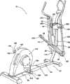
图1示出了根据本发明的一示例性实施例的后安装或后机构型椭圆健身器的立体图;Figure 1 shows a perspective view of a rear mounted or rear mechanism configuration elliptical exerciser in accordance with an exemplary embodiment of the present invention;
图2示出了图1的示例性椭圆健身器在折叠、紧凑构造的立体图;Figure 2 shows a perspective view of the exemplary elliptical exerciser of Figure 1 in a folded, compact configuration;
图3示出了图1的示例性椭圆健身器具有从其相应驱动部件释放或脱开的往复脚部支承件的立体图;3 illustrates a perspective view of the exemplary elliptical exerciser of FIG. 1 with the reciprocating foot supports released or disengaged from their respective drive components;
图4示出了图1的示例性椭圆健身器的一往复脚部支承件在附连到相应驱动部件的支柱上的详细立体图;4 shows a detailed perspective view of a reciprocating foot support of the exemplary elliptical exerciser of FIG. 1 on a strut attached to a corresponding drive component;
图5示出了图4的示例性往复脚部支承件从驱动部件脱开或释放的详细立体后视图,以及根据一示例性实施例的锁定机构;Figure 5 shows a detailed perspective rear view of the example reciprocating foot support of Figure 4 disengaged or released from the drive member, and a locking mechanism according to an example embodiment;
图6示出了图1的示例性椭圆健身器的枢转机构的详细视图,其中整个基部支承结构在其靠近地面的非折叠状态以进行椭圆健身器的适当操作;6 shows a detailed view of the pivot mechanism of the exemplary elliptical exerciser of FIG. 1 with the entire base support structure in its unfolded state near the ground for proper operation of the elliptical exerciser;
图7示出了图1的示例性椭圆健身器的枢转机构的详细视图,其中基部支承结构的后部在其最上部旋转位置,且其中椭圆健身器在其紧凑构造;7 shows a detailed view of the pivot mechanism of the exemplary elliptical exerciser of FIG. 1 with the rear of the base support structure in its uppermost rotated position, and with the elliptical exerciser in its compact configuration;
图8示出了沿图6的线8-8截取的剖视图,示出了图6中所示枢转机构的各部件;Figure 8 shows a cross-sectional view taken along line 8-8 of Figure 6, showing the components of the pivot mechanism shown in Figure 6;
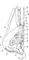
图9示出了根据本发明的另一示例性实施例的后安装或后机构型椭圆健身器的侧视图;以及Figure 9 shows a side view of a rear mounted or rear mechanism configuration elliptical exerciser in accordance with another exemplary embodiment of the present invention; and
图10示出了图9的示例性椭圆健身器的详细侧视图,其中基部支承结构包括辅助用户折叠椭圆健身器用的液压致动器形式的辅助机构。10 illustrates a detailed side view of the exemplary elliptical exerciser of FIG. 9, wherein the base support structure includes an assisting mechanism in the form of a hydraulic actuator to assist the user in folding the elliptical exerciser.
具体实施方式Detailed ways
本发明示例性实施例的以下详细说明参照附图,附图形成其一部分且其中以说明方式示出了实践本发明的示例性实施例。尽管充分详细地描述了这些示例性实施例以使本技术领域的技术人员能够实践本发明,但是应当理解也可实现其它实施例且可对本发明进行各种改变而不背离本发明的精神和范围。因此,如图1至10表示的本发明的实施例的以下更详细的说明不意指限制要求的本发明的范围,而是仅表示说明目的而不是限制地描述本发明的特征和特点、阐述本发明操作的最佳模式、并足以使本技术领域的技术人员能够实践本发明。因而,本发明的范围仅由所附权利要求书限定。The following detailed description of exemplary embodiments of the invention refers to the accompanying drawings, which form a part hereof, and in which are shown by way of illustration exemplary embodiments for practicing the invention. While these exemplary embodiments have been described in sufficient detail to enable those skilled in the art to practice the invention, it should be understood that other embodiments can be implemented and that various changes can be made in the invention without departing from the spirit and scope of the invention. . Accordingly, the following more detailed description of the embodiments of the present invention as represented in FIGS. the best mode of operation of the invention and are sufficient to enable those skilled in the art to practice the invention. Accordingly, the scope of the invention is limited only by the appended claims.
参照附图会最好地理解本发明的以下详细说明和示例性实施例,其中本发明的元件和特征始终用标号表示。The following detailed description and exemplary embodiments of the invention are best understood by referring to the accompanying drawings, wherein elements and features of the invention are indicated by reference numerals throughout.
本发明描述和特写了一种健身器,尤其是具有一个或多个可折离部件的椭圆或椭圆型健身器,该可折离部件便于将椭圆健身器折叠成紧凑构造,并更尤其是竖立紧凑构造。在一示例性实施例中,椭圆健身器可包括位于其支撑框架上的枢转连结件、或可折离连结件。可折离连结件可通过可折离往复脚部支承件来补充,且椭圆健身器还可包括该可折离往复脚部支承件,该脚部支承件进一步便于椭圆健身器折叠成紧凑构造。The present invention describes and features an exercise machine, particularly an elliptical or elliptical-type exercise machine having one or more breakaway parts that facilitate collapsing the elliptical into a compact configuration and, more particularly, standing Compact construction. In an exemplary embodiment, the elliptical exerciser may include pivotal linkages, or breakaway linkages, on its support frame. The breakaway links may be supplemented by, and the elliptical exerciser may also include, breakaway reciprocating foot supports that further facilitate folding of the elliptical exerciser into a compact configuration.
开始,尽管本文描述的原理、健身器、系统、装置、组件、机构以及方法主要是根据它们在具有后安装驱动部件或使用摇臂的曲柄的这些类型的椭圆健身器中的使用进行讨论的,但本技术领域的普通技术人员会理解这些原理、健身器、系统、装置、组件、机构和方法适于(不要过多的试验)用于具有前部安装构造的椭圆健身器或其它类似类型的健身器,其中封闭路径通过诸如在前机械型健身器上前安装驱动部件,或通过其它方式产生,并同样适用于具有静止或固定把手或手把的那些类型的健身器上。Initially, although the principles, exercise machines, systems, devices, assemblies, mechanisms, and methods described herein are discussed primarily in terms of their use in these types of elliptical trainers with rear mounted drive components or cranks using rocker arms, However, those of ordinary skill in the art will understand that these principles, exercise machines, systems, devices, assemblies, mechanisms and methods are suitable (without undue experimentation) for use with elliptical trainers or other similar types of trainers having a front-mounted configuration. Exercise machines in which closed paths are created by front mounting drive components such as on front mechanical type exercise machines, or by other means, and are equally applicable to those types of exercise machines having stationary or fixed handles or handlebars.
本发明提供了优于许多现有相关椭圆健身器的几个显著优点,其中一些在这里和以下整个更详细说明中有所叙述。首先,通过提供可松开或可拆开往复脚部支承件,椭圆健身器可包括位于大约中心或附近并远离其两端的枢转连结件。第二,通过设置远离两端的大约中心定位的枢转连结件,椭圆健身器能够折叠成比现有相关健身器更紧凑的构造。第三,本发明使椭圆健身器能够以竖直位置储存,而不是卧姿。这使椭圆健身器能够装入比其它方式能更紧的存储空间。考虑到以下阐述的详细说明书,参照附图每个上述优点会变得明显。这些优点并不意味着任何方式的限制。事实上,在实践本发明时,本技术领域的一技术人员会理解可实现其它优点,而不是在此具体引述的那些。The present invention provides several significant advantages over many prior related elliptical trainers, some of which are described here and throughout the more detailed description below. First, by providing releasable or detachable reciprocating foot supports, an elliptical trainer may include pivotal links located at or near its center and away from its ends. Second, by providing approximately centrally located pivot linkages away from the ends, the elliptical exerciser can be folded into a more compact configuration than related prior exercisers. Third, the present invention enables the elliptical to be stored in an upright position, rather than a prone position. This allows the elliptical to fit into tighter storage spaces than would otherwise be possible. Each of the above advantages will become apparent upon consideration of the detailed description set forth below with reference to the accompanying drawings. These advantages are not meant to be limiting in any way. Indeed, in practicing the invention, one skilled in the art will understand that other advantages may be realized than those specifically recited herein.
参照图1和2,示出的是根据本发明一示例性实施例后安装或后机械型椭圆健身器的各立体图。具体地说,图1和2示出了椭圆健身器10,包括第一往复脚部支承件14,该支承件14具有第一端18、第二端22和设置在其上并位于第一端18和第二端22之间的相应脚垫30,该脚垫尺寸和结构设置成接纳用户的脚。与第一往复脚部支承件14相补充的是第二往复脚部支承件44,该支承件44具有第一端48、第二端52和设置在其上并位于第一端48和第二端52之间的相应脚垫60,该脚垫尺寸和结构也设置成接纳用户的脚。第一和第二往复脚部支承件14和44彼此侧向隔开,使得相应脚垫30和60中的每个分别能够舒适地接纳用户的相应脚并便于用户面向前方的跨步运动的进行。在此应当注意,脚垫30和60可分别联接、安装、或其它方式定位在往复脚部支承件14和44上。还应当注意,或者往复脚部支承件14和44可构造成没有脚垫,使用户直接站在往复脚部支承件14和44的上表面上。在该实施例中,将防滑材料加到往复脚部支承件的表面上以辅助保持可靠的立足。Referring to Figures 1 and 2, there are shown various perspective views of a rear-mounted or rear-mechanical elliptical exerciser in accordance with an exemplary embodiment of the present invention. Specifically, Figures 1 and 2 show an
往复脚部支承件14和44,以及健身器的其它部件,诸如驱动组件,由基部支承结构70支承在支持表面上。支承结构70构造成对健身器10的部件提供结构和平移支承,并还与地面或其它合适表面交界。基部支承结构70大致限定健身器10的占地面积的大小。The reciprocating foot supports 14 and 44 , as well as other components of the exercise machine, such as the drive assembly, are supported by the
有利的是,本发明的基部支承结构70构造成可枢转或可折离,因此使椭圆健身器10能够根据需要折叠成紧凑构造并然后再展开。具体地说,基部支承结构70具有一些枢转装置,将基部支承结构70的至少两个部件枢转地联接在一起,并使基部支承结构的至少一部分能够围绕基部支承结构70的至少另一部分折叠,用于使椭圆健身器紧凑的目的(例如用于储存目的)(见图2)。换言之,基部支承结构70包括通过枢转机构或组件可枢转地彼此联接的第一或前部分64(或前基部支承件64)和第二或后部分66(或后基部支承件),其中第一或前部分64和第二或后部分66构造成可至少部分地彼此折离和折叠以实现紧凑结构构造,如下文更详细描述的那样。枢转位置或枢转连结件的位置较佳地远离基部支承结构的两端设置或从该两端偏离一定距离,且同样,如果适用,偏离竖直支承件86一定距离。由于枢转连结件定位在该位置,可折离基部支承结构70提供基部支承结构的一部分以在其对应部分向上旋转且椭圆健身器折叠成紧凑构造时保持与地面或地板表面接触。基部支承结构70的保持与地面接触或靠近地面的部分,在该情况下是纵向支撑梁74的前部64和横向梁82,构造成对在其折叠构造的椭圆健身器提供必要支承和稳定性。Advantageously, the
在图1和2的示例性实施例中,基部支承结构70包括工字梁构造,其中工字梁构造包括用作主要支承构件的纵向支承梁74、以及位于纵向支承梁74每端周围并沿相反方向从其每端延伸的第一和第二侧向横向梁78和82。橡胶或塑料帽98安置在横向梁78和82的端部上。根据本发明,基部支承结构70至少包括可相对于彼此枢转的两个部件,即第一或前部分64和第二或后部分66。在所示实施例中,纵向支承梁74由可枢转地联接在一起的两个分开构件组成。纵向支承梁74的前部构件与第二横向梁82一起组成基部支承结构70的前部分64。同样,纵向支承梁74的后部构件与第一横向梁78一起组成基部支承结构70的后部分66。前部分64和后部分66中的每个构造成当用户运行椭圆健身器10时靠近地面或地板表面。In the exemplary embodiment of FIGS. 1 and 2 , the
如上所述,椭圆健身器10包括构造成便于前部分和后部分相对于彼此枢转的枢转机构或组件。如图所示,在一示例性实施例中,椭圆健身器10包括沿着纵向支承梁74的纵向长度并在纵向支承梁74的纵向两端之间定位的枢转机构或组件170。在所示实施例中,枢转机构170定位在离开纵向支承梁74的中点一定距离处,因此容纳驱动组件112,包括封装驱动组件的所有或一部分部件的壳体或封壳114。为了一个或多个目的,诸如将健身器10折叠成如图2所示的紧凑构造,枢转机构170构造成使后部分64能够在离开地面或地板表面的向上方向并相对于前部分66折离和枢转,该前部分66保持与地面接触,因此便于并使基部支承结构70能够折离并重新设置驱动组件112。As noted above,
如图所示,示例性椭圆健身器10是具有构造成支承驱动组件112的基部支承结构70的后部分64的后机械型机器。由于驱动组件112支承在后部分64上,后部分64围绕前部分66的向上旋转用于使驱动组件112,以及其几个部件也朝向竖直支承件86向上向内枢转,因此使椭圆健身器10紧凑。As shown, the exemplary
考虑到后部分66,以及因此驱动组件112的向上和向内旋转,基部支承结构70、以及其各部件,尤其是前部分64和后部分66,以及枢转机构170构造成包括必要的尺寸和强度来将驱动组件112支承在垂直或基本上垂直位置,以及任何数量的中间位置。这对本技术领域的技术人员是显而易见的。To allow for upward and inward rotation of
此外,基部支承结构70可以是任何合适设计,诸如任何合适的框架状结构或其它构造。此外,基部支承结构70可包括构造成可操作地联接在一起以形成基部支承结构70的多个不同部件。实质上,基部支承结构70可包括构造成按预期运行和操作的任何合适的设计,且因此本文讨论且图中示出的工字梁构造并不意味着任何方式的限制。Furthermore,
为了辅助用户致动椭圆健身器的折离功能并使后部分64向上枢转或旋转,本发明可具有用框架或椭圆健身器的其它支承件形成的一个或多个把手。如图1和2所示,椭圆健身器10包括设置在驱动组件112后部的把手116。把手116可联接到为椭圆健身器10提供必要支承的各框架部分(未示出)或者是各框架部分的一部分。把手116可包括任何构造。把手116用于辅助用户为了折叠椭圆健身器10的目的而将后部分66举离地面,如本文所述的那样。把手116还用于辅助用户展开和将后部分66降低放回地面。封壳114还可包括开口以接纳把手,或者可以是把手本身的一部分。把手在椭圆健身器上的位置并不关键,只要它设置在想要旋转和折叠的椭圆健身器的一部分上即可,在图1-3的示例性实施例的情况下是后部分66。To assist the user in actuating the fold-off function of the elliptical and pivoting or rotating the
图2还示出了本发明的锁定结构,其中一旦基部支承结构70的后部分66向上枢转并进入一个或多个折叠位置就可将其锁定在合适位置。基部支承结构70的锁定机构可包含在或支承在基部支承结构70,或其部件之一内,并可构造成将基部支承部分锁定在多个中间位置中的任何一个位置,以及椭圆健身器在其最紧凑构造的完全旋转位置。此外,松开机构可构造成可操作锁定机构以提供锁定机构的选择和致动的松开。如图2所示,后部分,且尤其是纵向支承梁74的后部构件,包括构造成按压时触发锁定机构松开的按钮。当然,也可采用其它类型的松开机构。按钮用于致动锁定机构的一个或多个部件以放开后部分,其中然后后部分可向下枢转。FIG. 2 also illustrates the locking structure of the present invention, wherein the
图1-3示出了示例性椭圆健身器10的其它特征。从纵向支承梁74向上延伸有垂直或竖直支承件86,其中该支承件用于辅助第一摇臂102和第二摇臂122的支承。竖直支承件86可包括或支承各种已知物件或组件,诸如用户界面、固定的把手杆、杯保持件、杂志或书支架等。在所示实施例中,第一和第二固定把手杆90和94支承在竖直支承件86的顶部。Additional features of the exemplary
示例性椭圆健身器10的竖直支承件86可包括任何形状或构造。在一特定实施例中,竖直支承件86包括弯曲段88,该弯曲段包括远离驱动组件112弯曲的朝外定向的弯曲部。该弯曲段88构造成当基部支承结构70,以及因此的驱动组件112向上枢转以将椭圆健身器10折叠成本文讲授的更紧凑构造(见图2)时,接纳驱动组件112、或封装或以套装关系包围驱动组件112的各部件的封壳或壳体(示出为封壳114)。通过使竖直支承件86弯曲,并根据枢转连结件或枢转机构170的位置,后部分66可在被竖直支承件86挡住之前在更大旋转范围内旋转,因此实现比竖直支承件86不弯曲时更紧凑的折叠构造。如本技术领域的技术人员会认识到的那样,弯曲段88沿着竖直支承件86的位置,以及弯曲的程度或半径,会很大程度上取决于枢转机构170的位置和折叠时驱动组件112和/或封壳114的产生的垂直或竖直停留位置。此外,弯曲段88的弯曲的程度和半径会取决于驱动组件112的尺寸和构造或封装驱动组件112的各部件的封壳。当然,竖直支承件86可包括弯曲、线性、样条线或其它构造、或它们的任何组合。The vertical supports 86 of the exemplary
参照图1-3,第一和第二往复脚部支承件14和44的第二端22和52中的每个可以本技术领域公知的任何方式被支承,以使健身器10、尤其是往复脚部支承件14和44的往复运动能够运行。例如,第一和第二往复脚部支承件14和44相应的第二端22和52可如公知那样通过沿轨道引导或滚动的辊子支承。但是,在本文所示的示例性实施例中,第一和第二往复脚部支承件14和44的第二端22和52可枢转地分别与第一和第二摇臂102和122联接。第一和第二摇臂102和122包括具有上部和下部端的细长连接件并构造成在竖直支承件86的相对左侧和右侧侧向隔开。第一摇臂102可使用任何已知的联接装置枢转地联接到锚定件104,该锚定件是竖直支承件86的部件或延伸部。锚定件104构造成支承第一摇臂102并使第一摇臂102能够围绕轴线106枢转。以同样方式,第二摇臂122可枢转地联接到也固定到竖直支承件86的锚定件124。锚定件124构造成支承第二摇臂122,并使第二摇臂122能够围绕轴线126枢转。这样,第一和第二摇臂102和122基本上可枢转地联接到竖直支承件86。当然,联接构造的该具体类型并不意味着以任何形式限制可能的和对本技术领域的技术人员明显的其它构造,本文考虑了其每种构造。1-3, each of the second ends 22 and 52 of the first and second reciprocating foot supports 14 and 44 may be supported in any manner known in the art to allow the
第一和第二摇臂102和122的下端可使用任何已知联接装置分别枢转地联接到第一和第二往复脚部支承件14和44的第二端22和52。第一和第二往复脚部支承件14和44和第一和第二摇臂102和122构造成健身器10运行时分别围绕枢转点110和130枢转。摇臂102和122分别用于在健身器10运行时引导第一和第二往复脚部支承件14和44沿弧形封闭路径的摇摆式往复运动。围绕该弧形封闭路径行进提供了有效模拟用户的跨步的运动的基本上水平向前向后分量。由于往复脚部支承件14和44在它们各自第二端的联接构造,脚垫30和60行进的封闭路径实际上是大致椭圆形,大部分路径包括水平分量,尽管也有垂直分量。The lower ends of the first and
此外,摇臂102和122构造成使往复脚部支承件14和44能够在摇臂102和122上向上枢转或折叠,在该处它们可以可松开地联接到竖直支承件86上,或其部件部分的一个或多个上。如图1所示,第二摇臂122包括延伸支架128,用于枢转地将往复脚部支承件44联接到摇臂122,以及使往复脚部支承件44能够向上枢转以使它可以可松开地联接到由竖直支承件86支承的锚定件124。尽管未示出,但第一摇臂102包括类似的支架。In addition,
椭圆健身器10还包括第一和第二驱动部件,示出为使用任何已知支承装置围绕基部支承结构70可旋转地支承的第一和第二曲柄或曲柄臂140和160。考虑到可将本发明包含在包括能够围绕枢转点以同心或偏心方式旋转的各种类型驱动部件的椭圆健身器中。但是,为了讨论的目的,示例性驱动部件描述为曲柄140和160。曲柄140和160较佳地相对于彼此固定并构造成围绕共同枢转轴线沿相同重复圆形路径行进。第一和第二曲柄140和160还构造成彼此异相180°以便于第一和第二脚部支承件14和44上的交替往复运动并模拟用户的自然交替跨步。每个曲柄较佳地包括固定的或不可调节的尺寸或长度。The
为了使基部支承结构70能够折离或其一部分能够向上枢转或旋转以将椭圆健身器折叠成更紧凑构造,本发明还具有构造成从联接到其上的相应驱动部件拆开的第一和第二往复脚部支承件14和44(见图2和3)。这样,总体参见图1、2或3,椭圆健身器10还包括可松开或可拆开地将往复脚部支承件的第一端分别联接到驱动部件140和160的装置。用于可松开或可拆开联接的装置意图使往复脚部支承件14和44的每个从其相应驱动部件拆开以使基部支承结构70能够折离并折叠成紧凑构造,如图2所示。如公知的那样,为了实现模拟跨步运动,往复脚部支承件14和44设计成在从驱动部件的枢转轴线径向偏离的位置联接到相应驱动部件140和160上,因此,使往复脚部支承件14和44中的每个能够围绕封闭路径经过或行进,其中封闭路径包括一个跨步长度。如本技术领域公知的那样,跨步长度至少部分由往复脚部支承件的附连点和曲柄的枢转轴线之间的相对距离指示。第一和第二往复脚部支承件14和44的第一端18和48围绕相应曲柄140和160的远端或自由端可旋转地被支承。由于这样支承,使往复脚部支承件14和44能够在健身器10运行时沿着封闭路径向后向前向上向下移动。In order to allow the
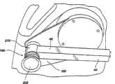
将往复式脚部支承件可松开地联接到相应驱动部件的装置可包括多个不同的联接构造,附图中示出且本文描述了一些这样的构造。具体地说,如图3、4和5所示,一示例性联接装置包括联接构造190,其中第一和第二支柱194和206分别联接到曲柄140和160并从曲柄140和160向外垂直延伸。示出支柱194和206直接联接到曲柄140和160。第一和第二支柱194和206的每个还分别包括旋转套环198和210,构造成分别可旋转地接纳和联接第一和第二往复脚部支承件14和4的第一端18和48。可旋转套环198和210构造成使第一和第二往复脚部支承件14和44在联接于支柱194和206时能够围绕旋转轴线旋转,其中旋转轴线从曲柄140和160的枢转点径向偏离一定距离并与其垂直。因此,当健身器10运行且第一和第二曲柄140和160沿它们相应的圆形路径旋转时,支柱194和206提供的往复脚部支承件14和44相对于曲柄14和44的枢转轴线的旋转轴线的偏离位置,以及往复脚部支承件14和44的适当支承的第二端22和52,引起往复脚部支承件14和44经过椭圆形封闭路径。Means for releasably coupling a reciprocating foot support to a corresponding drive member may include a number of different coupling configurations, some of which are shown in the drawings and described herein. Specifically, as shown in FIGS. 3 , 4 and 5 , an exemplary coupling arrangement includes a
如上所述,第一和第二往复脚部支承件14和44中的每个分别可移除地联接到第一和第二支柱194和206。在所示实施例中,往复脚部支承件14和44的第一端18和48分别各包括钩件,示出为214和218,构造成分别可松开地配合和联接到第一和第二支柱184和206的旋转套环198和210。钩件214和218各包括半径稍大于旋转套环的半径的半圆形构造,因此使钩件214和218能够与旋转套环配合和匹配。半圆形钩件的开口设置成面向下的定向,或背离往复脚部支承件14和44的顶部表面的定向,以使往复脚部支承件14和44能够向下旋转以可松开地配合支柱,并支承作用在上面的任何向下的或其它的力,诸如通常由于用户运行椭圆健身器10施加的那些。为了将往复脚部支承件附连到驱动部件的支柱上,往复脚部支承件的钩件与支柱对齐并使其配合并搁置在支柱的旋转套环上。在该位置,钩件使往复脚部支承件和椭圆健身器能够按要求作用,使钩件和旋转套环能够围绕支柱的轴旋转。当要求折叠椭圆健身器时,仅通过举起往复脚部支承件以脱开钩件就可从支柱松开往复脚部支承件。一旦脱开或松开,往复脚部支承件就可向上旋转并使其抵靠竖直支承件86或其部件。可对往复脚部支承件14和44中的每个进行该程序,如图2-5所示。在所示实施例中,锚定件104和124各包括附连到其上的磁铁,示出为磁铁230和232,构造成可松开地与相应往复脚部支承件14和44联接以便于折叠圆形健身器10,如本文所述。当然,可使用且本文考虑了对本技术领域的技术人员明显的用于将往复脚部支承件联接到竖直位置的其它装置。例如,往复脚部支承件可使用条带、夹件等联接到竖直支承件,或其部件之一。在另一实施例中,椭圆健身器可包括构造成当枢转地联接到第一和第二摇臂时随着往复脚部支承件运行的棘齿系统。As noted above, each of the first and second reciprocating foot supports 14 and 44 are removably coupled to the first and
如图5所示,往复脚部支承件还可包括构造成将往复脚部支承件暂时锁定到驱动部件,尤其是驱动部件的支柱的锁定机构。例如,如图5所示,且在一示例性实施例中,钩件214和218可包括与其互补的铰接件222,也是半圆形式的且半径稍大于支柱的半径。铰接件222可定向在与钩件相对的位置以能够在附连往复脚部支承件时与支柱的相反侧配合。此外,铰接件222可包括某种闭锁件或锁定件,示出为闭锁件224,构造成当往复脚部支承件向下设置时闭锁或锁定所述钩件,以能使用椭圆健身器,且当需要折叠椭圆健身器时解锁或解开。闭锁件224构造成可松开地配合相应孔(未示出)以将构件22固定在适当位置。As shown in FIG. 5 , the reciprocating foot support may also include a locking mechanism configured to temporarily lock the reciprocating foot support to the drive member, particularly the strut of the drive member. For example, as shown in FIG. 5 , and in an exemplary embodiment,
在另一示例性实施例中,如图5所示,用于往复脚部支承件的锁定机构可包括闭锁组件234。闭锁组件234可包括使用任何已知安装装置,诸如螺钉或螺栓安装到往复脚部支承件14的第一端18下侧的闭锁基部236。闭锁基部236构造成支承触发器238,且偏移的闭锁件240设计和构造成可松开地配合驱动组件的支柱的旋转套环或其它部分(见图1中的旋转套环198、支柱194、以及驱动组件112),以在往复脚部支承件14和椭圆健身器在正常操作和运行位置时将往复脚部支承件14锁定到支柱和驱动组件上。闭锁件240包括弯曲表面242,该弯曲表面的半径与支柱的旋转套环或其它部分的半径相应。闭锁件240还包括形成在相对于往复脚部支承件14的纵向轴线的一斜面上的压力表面244,其中压力表面设计和构造成在致动触发器238的情况下便于闭锁件240响应于大到能克服诸如弹簧(未示出)的偏置件预设在闭锁件240上的负载的负载而移动。In another exemplary embodiment, the locking mechanism for the reciprocating foot support may include a latch assembly 234 as shown in FIG. 5 . The latch assembly 234 may include a latch base 236 mounted to the underside of the
触发器238一端通过从闭锁基部236延伸的锚定件246支承,而另一端通过滑动件248支承。锚定件246可枢转地将触发器238联接到闭锁基部236。更具体地说,锚定件246构造成将触发器238的一端接纳在其中并便于其在致动触发器238时旋转以从支柱松开往复脚部支承件14。滑动件248可滑动地联接到闭锁基部236并构造成在闭锁件240联接到滑动件248上时能够使闭锁件240移动。触发器238还包括形成在其上的狭槽250,它构造成也便于闭锁滑动件240的松开和移动。在所示示例性实施例中,狭槽250包括具有水平和垂直部分的L形构造。滑动件248还包括容纳在孔251内的销249。销249构造成响应闭锁件240的双向移动而沿着狭槽移动。The trigger 238 is supported at one end by an anchor 246 extending from the latch base 236 and at the other end by a slider 248 . Anchor 246 pivotally couples trigger 238 to latch base 236 . More specifically, the anchor 246 is configured to receive one end of the trigger 238 therein and facilitate its rotation when the trigger 238 is actuated to release the
闭锁组件234还包括在靠近往复脚部支承件14的端部18的端部处联接或安装到钩件214的板252。板252包括形成在其上的狭槽以使闭锁件240在双向移动时能够穿过其中。The latch assembly 234 also includes a plate 252 coupled or mounted to the
为了致动锁定机构,或为了使闭锁件240能够从其锁定位置松开或撤除,可致动触发器238。这使容纳在滑动件248上孔251内的销249从狭槽250的垂直部分过渡到狭槽250的水平部分,由此使销249和滑动件248能够响应于由施加负载引起的闭锁件240的移动而移动(即从支柱举起往复脚部支承件14)。实质上,触发器238用于松开闭锁件240不能够使其能够在负载下移动。To actuate the locking mechanism, or to enable release or removal of the latch 240 from its locked position, the trigger 238 may be actuated. This transitions the pin 249 received in the hole 251 on the slider 248 from the vertical portion of the slot 250 to the horizontal portion of the slot 250, thereby enabling the pin 249 and slider 248 to respond to the latch 240 caused by the applied load. (ie lift the
也可采用且本文考虑了其它类型的闭锁机构,诸如条带、弹性件等。Other types of latching mechanisms, such as straps, elastics, etc., may also be used and are contemplated herein.
这里尤其要注意的是第一和第二往复脚部支承件可包括构造成可松开地将它们相应的第一端联接到椭圆健身器的驱动部件上的任何类型的机构、组件等。这样,本文讨论且附图示出的示例性实施例,诸如包括设置在第一端的钩件,并不意味着任何方式的限制。实际上,本技术领域的技术人员会认识到将往复脚部支承件可松开地联接到驱动部件以实现本文想要的椭圆健身器的折叠的其它方式。考虑了这些替代方式,并意味着落入要求的本发明的范围。Of particular note herein is that the first and second reciprocating foot supports may comprise any type of mechanism, assembly, etc. configured to releasably couple their respective first ends to the drive member of the elliptical exerciser. As such, the exemplary embodiments discussed herein and illustrated in the figures, such as including a hook disposed at a first end, are not meant to be limiting in any way. Indeed, those skilled in the art will recognize other ways of releasably coupling the reciprocating foot supports to the drive members to achieve the folding of the elliptical exerciser contemplated herein. These alternatives are contemplated and are meant to fall within the scope of the claimed invention.
参照图6-8,示出了根据本发明一示例性实施例的基部支承结构70和使后部分66能够向上折离或折叠到前部分64上的枢转机构170的各种详细图示。如图所示,图6示出了在其降低的非折叠状态的基部支承结构70,驱动组件(未示出)和基部支承结构70的后部分66支承在地面或地板表面上并靠近地面放置,在该位置用户可运行椭圆健身器;图7示出了在折叠、竖直位置的基部支承结构70,致使椭圆健身器从其非折叠状态转换到折叠、紧凑构造;且图8示出了沿图6的线8-8截取的基部支承结构70和枢转机构170的详细剖视图。Referring to FIGS. 6-8 , there are shown various detailed illustrations of the
具体地说,参照图6-8,枢转机构170提供基部支承结构70的纵向支承梁74内的枢转连结件。枢转机构170包括枢转销172,该销可操作地保持在形成在或以其它方式定位在纵向支承梁74的第二构件76的端部的适当销支承件174内。枢转销172用于可枢转地将销支承件174和第二或第四构件76联接到在第一构件75上形成的互补沟槽176内的纵向支承梁74的第一或后部构件75,因此将基部支承结构70的前部分64和后部分66枢转地联接在一起。沟槽176构造成为了所述目的接纳前部构件、或其一部分。Specifically, referring to FIGS. 6-8 ,
枢转机构170还包括阻挡或限制系统。在所示示例性实施例中,限制系统包括位于纵向支承梁74的第一构件75的沟槽176内的阻挡件182。阻挡件182包括构造成在销支承件174的侧壁180上形成的相应狭槽178内配合并滑动的突起部184。由于固定到纵向支承梁74的第一构件75,在基部支承结构70的后部旋转以折叠椭圆健身器时,突起部184在狭槽178内行进。当突起部184接触狭槽178的上边缘时,实现完全旋转。这样,该限制系统阻止了基部支承结构70的后部分66的进一步或过度旋转。实际上,限制系统,且尤其是突起部184和狭槽178用于限制基部支承结构70,尤其是后部分66在向上方向的旋转。突起部184和狭槽178可构造成使后部分66旋转的任何适当范围在0°至130°之间。如图8所示,可旋转基部支承结构70的后部分66,并可改变椭圆健身器,从后部分66位于地面或地板表面上的约0°位置到其中后部分66在其完全旋转、竖直和折叠状态(以虚线示出)的大约110°的折离位置。在该折叠状态,驱动组件(见图2中的驱动组件112)被支承离开地面或地板表面,且椭圆健身器构造成包括紧凑构造。在图2和8所示的示例性实施例中,突起部184和狭槽178构造成使后部分66能够旋转通过90°,其中驱动组件112能够嵌入竖直支承件86的弯曲段88,因此使椭圆健身器能够实现更紧凑的构造。
参照图9和10,示出了根据本发明的另一示例性实施例的椭圆健身器的各侧视图。如图所示,椭圆健身器310包括与上述健身器类似的设计。这样,在适用的地方将上述说明包含在此。但是,在该实施例中,椭圆健身器310包括不同构造的基部支承结构370。具体地说,基部支承结构370包括铰接到后部分366的前部分364,因此使后部分366,以及支承在其上的驱动组件412能够向上枢转到折叠位置。将基部支承结构370的后部分366可枢转地联接到前部分364的枢转机构470,包括纵向支承梁374的第一构件375形式的第一铰接部件、以纵向支承梁374的第二构件376的上部延伸部分486形式的第二铰接部件486,以及一枢转销488。Referring to Figures 9 and 10, various side views of an elliptical exerciser according to another exemplary embodiment of the present invention are shown. As shown, the
图9和10还示出了设计成辅助用户举起后部分366和相应驱动组件412离开地面并将它们旋转到折叠位置的辅助机构。在所示示例性实施例中,辅助机构包括液压致动器432。液压致动器432包括液压缸436和可操作地支承在液压缸436内的活塞434。液压致动器432在一端联接到纵向支承梁374的前部构件375,且在相反端联接到纵向支承梁374的第二或后部构件376。此外,液压致动器432示出为从枢转机构470的枢转销488偏离设置。该非平面设置使液压致动器432能够辅助折叠椭圆健身器。9 and 10 also illustrate an assist mechanism designed to assist the user in lifting the
在将往复脚部支撑件314和344从它们相应驱动部件(见驱动部件460)松开时,且液压致动器432在致动时在第一和第二构件375和376两者上,或在前部分364和后部分366上施加相反的力,这使得后部分366围绕枢转销488枢转并朝向折叠位置向上旋转。换言之,液压致动器432引起后部分366围绕枢转销或枢转点488的运动,该运动用于辅助用户举起后部分366并将椭圆健身器折叠到紧凑构造。When the reciprocating foot supports 314 and 344 are released from their respective drive members (see drive member 460), and the
该辅助机构还可构造成为椭圆健身器折叠到其紧凑构造,以及椭圆健身器从其紧凑构造展开到其非折叠位置以准备运行或使用提供辅助。换言之,本发明考虑了包括双辅助功能,或双向辅助功能的辅助机构。还考虑到辅助机构可构造成包括单个辅助功能,其中辅助机构提供椭圆健身器的折叠或展开的单向辅助。The assisting mechanism may also be configured to assist in the folding of the elliptical exerciser into its compact configuration and in the unfolding of the elliptical exerciser from its compact configuration to its unfolded position ready for operation or use. In other words, the present invention contemplates assist mechanisms that include dual assist functions, or bi-directional assist functions. It is also contemplated that the assist mechanism may be configured to include a single assist function, wherein the assist mechanism provides one-way assistance in folding or unfolding the elliptical trainer.
该辅助机构可包括其它类型的致动器,诸如气动致动器。此外,辅助机构可包括可由枢转机构操作的棘齿系统。The auxiliary mechanism may include other types of actuators, such as pneumatic actuators. Furthermore, the auxiliary mechanism may comprise a ratchet system operable by the pivot mechanism.
图10还示出了位于形成这驱动组件412内把手416内的触发器420。触发器420通过连接装置421可操作地联接到液压致动器432,该连接装置穿过框架的各结构支承部件,诸如构件421。连接装置421可包括现有技术领域已知到任何类型的机械或电气连接。实质上,触发器420设计成为用户提供需要时致动液压致动器432的装置。此外,触发器420用于使用户能够将后部分366设置在任何中间折叠位置。实际上,触发器420的松开解除了液压致动器432,该解除可在后部分366的旋转可用范围内的任何时间发生。液压致动器432较佳地由合适尺寸和强度组成以将后部分366和支承的驱动组件312支承在任何中间位置。触发器420提供另一有用功能,即在折叠或展开椭圆健身器310时防止基部支承结构370的不经意跌落或向下旋转。这可通过这任何时间解除触发器来实现。FIG. 10 also shows a
液压致动器432可支承在纵向支承梁374的第二构件376的外侧或这第二构件376的内部管内。The
图9和10还示出了位于后部分366上的第二把手418,它也设计成辅助用户举起后部分366并将椭圆健身器310折叠到紧凑构造。图中示出的把手418和416的具体位置并不表示任何方式的限制。9 and 10 also show a
再参照图1-3,可通过将用户的双脚放到相应往复脚部支承件14和44上的相应脚垫30和60上来运行健身器10。曲柄140和160的旋转位置和往复脚部支承件14和44围绕往复脚路径形成的位置并不重要,因为这些部件可在任何位置启动健身器。为了进行健身运动并使往复脚部支承件14和44经过封闭路径,用户开始快步动作,这用于在往复脚部支承件14和44上产生力以使它们根据它们的初始启动位置沿向前或向后方向移动。一旦完成单次跨步,每个往复脚部支承件改变方向以完成相反方向的跨步。实质上,当一往复脚部支承件向前运动时,另一往复脚部支承件在使得力从相对的往复脚部支承件施加到每个往复脚部支承件上的第一和第二曲柄140和160的固定联接关系、从倾向于分别向每个往复脚部支承件14和22施加压力或拉力的摇臂102和122、以及从在往复脚部支承件14和18上施加力的用户的脚产生的力的结合的作用下向后移动。例如,当健身器10在图1所示的位置,主要放置在第一往复脚部支承件14的第一脚垫30上的用户的引力质量,即重量引起第一曲柄140向下旋转,因此引起往复脚部支承件14向下和向前运动以及向下和向后通过半个循环的旋转。主要在第一往复脚部支承件14上的用户的重量产生的重力传递到第一曲柄140,因此引起第一曲柄140围绕其枢转点110顺时针方向(从健身器10的右侧看)旋转。相反,第二往复脚部支承件44向上和向后以及向上和向前移动通过半个周期当转动,第二曲柄160则以类似方式起作用。用户执行的跨步运动可按照实现一系列锻炼跨步所要求的频率重复。这两个往复脚部支承件的交替往复运动提供了用户可承担的更自然跨步运动的模拟。确实,交替的往复运动使用户能够实现一系列跨步,与一个人在常规或改变的步法时非常相似。Referring again to FIGS. 1-3 ,
在完成健身后,或为了一个或多个其它目的,可将健身器10折叠成更紧凑构造以便于储藏或运输。这通过将每个往复脚部支承件从驱动部件松开或拆下并将它们向上旋转而不碍人并临时将它们联接到竖直支承件上的锚定件来完成。一旦将往复脚部支承件拆下且而不碍人,就使基部支承结构折离且后部分相对于前部分向上折叠,如本文所讨论的那样。After completing a workout, or for one or more other purposes,
前述详细说明书参照具体示例性实施例描述了本发明。但是,应当理解可进行各种更改和改变而不背离所附权利要求书阐述的本发明范围。详细说明书和附图应认为仅为说明而非限制,且所有这些更改或改变(如果有的话)都落入在此描述和阐述的本发明的范围内。The foregoing detailed specification has described the invention with reference to specific exemplary embodiments. However, it should be understood that various modifications and changes can be made without departing from the scope of the present invention as set forth in the appended claims. The detailed description and drawings are to be regarded as illustrative only and not restrictive, and all such modifications or changes, if any, are within the scope of the invention as described and illustrated herein.
更具体地说,尽管在此已描述了本发明的说明性示例性实施例,但本发明并不限于这些实施例,而是包括具有本技术领域的技术人员根据前述详细说明书理解的更改、省略、组合(例如各实施例的各方面的组合)、适应和/或改变的任何和所有实施例。权利要求书中的限制根据权利要求书中使用的语言进行宽泛的解释且不限于前述详细说明书中或进行申请时描述的实例,这些实例解释为非排除性的。例如,在本发明中,术语“较佳地”是非排除性的,它往往意味着“较佳地,但不限于”。任何方法或过程权利要求书中引述的任何步骤可以任何顺序执行且不限于权利要求书中提出的顺序。仅在以下所有情况用于存在于具体权利要求的限制定中的情况下采用的装置加功能或步骤加功能限定在于以下限定:a)清楚地叙述“用于…的装置”或“用于…的步骤”;b)清楚地叙述相应的功能;以及c)清楚地叙述结构、材料或支承该结构的作用。因而,本发明的范围仅由所附权利要求书和它们的法律同等物确定,而不是以上给出的说明书和实例。More specifically, although the illustrative exemplary embodiments of the present invention have been described herein, the present invention is not limited to these embodiments but includes modifications, omissions and modifications that those skilled in the art would understand from the foregoing detailed description. , combinations (eg, combinations of aspects of the various embodiments), adaptations, and/or alterations of any and all embodiments. The limitations in the claims are to be interpreted broadly according to the language used in the claims and not limited to the examples described in the foregoing detailed description or in the filing of the application, which examples are to be construed as non-exclusive. For example, in the present invention, the term "preferably" is non-exclusive and often means "preferably, but not limited to". Any steps recited in any method or process claims may be performed in any order and are not limited to the order presented in the claims. A means-plus-function or step-plus-function limit is employed only if all of the following are present in the context of a specific claim limitation: a) expressly recites "means for" or "for b) clearly state the corresponding function; and c) clearly state the structure, material or role of supporting the structure. Accordingly, the scope of the present invention is to be determined only by the appended claims and their legal equivalents, rather than by the description and examples given above.
Claims (23)
Applications Claiming Priority (3)
| Application Number | Priority Date | Filing Date | Title |
|---|---|---|---|
| US11/155,328 | 2005-06-16 | ||
| US11/155,328US7766797B2 (en) | 2004-08-11 | 2005-06-16 | Breakaway or folding elliptical exercise machine |
| PCT/US2006/023544WO2006138601A2 (en) | 2005-06-16 | 2006-06-16 | Breakaway or folding elliptical exercise machine |
Publications (2)
| Publication Number | Publication Date |
|---|---|
| CN101203281A CN101203281A (en) | 2008-06-18 |
| CN101203281Btrue CN101203281B (en) | 2010-10-27 |
Family
ID=37571229
Family Applications (1)
| Application Number | Title | Priority Date | Filing Date |
|---|---|---|---|
| CN2006800218359AExpired - Fee RelatedCN101203281B (en) | 2005-06-16 | 2006-06-16 | Breakaway or folding elliptical exercise machine |
Country Status (4)
| Country | Link |
|---|---|
| US (2) | US7766797B2 (en) |
| EP (1) | EP1917077B1 (en) |
| CN (1) | CN101203281B (en) |
| WO (1) | WO2006138601A2 (en) |
Families Citing this family (88)
| Publication number | Priority date | Publication date | Assignee | Title |
|---|---|---|---|---|
| US20060003869A1 (en)* | 2004-07-02 | 2006-01-05 | Johnson Tech. Co., Ltd. | Folding treadmill |
| US7740563B2 (en) | 2004-08-11 | 2010-06-22 | Icon Ip, Inc. | Elliptical exercise machine with integrated anaerobic exercise system |
| US7766797B2 (en) | 2004-08-11 | 2010-08-03 | Icon Ip, Inc. | Breakaway or folding elliptical exercise machine |
| US10814160B2 (en)* | 2005-11-04 | 2020-10-27 | Johnson Health Tech. Co., Ltd. | Stationary exercise apparatus |
| US7846071B2 (en)* | 2006-05-15 | 2010-12-07 | Johnson Health Tech Co., Ltd. | Stationary exercise apparatus |
| US7717828B2 (en) | 2006-08-02 | 2010-05-18 | Icon Ip, Inc. | Exercise device with pivoting assembly |
| US7658698B2 (en) | 2006-08-02 | 2010-02-09 | Icon Ip, Inc. | Variable stride exercise device with ramp |
| US20080161163A1 (en)* | 2006-12-28 | 2008-07-03 | Precor Incorporated | Supplemental resistance assembly for resisting motion of an exercise device |
| US7736279B2 (en)* | 2007-02-20 | 2010-06-15 | Icon Ip, Inc. | One-step foldable elliptical exercise machine |
| US7674205B2 (en) | 2007-05-08 | 2010-03-09 | Icon Ip, Inc. | Elliptical exercise machine with adjustable foot motion |
| US20080280733A1 (en)* | 2007-05-09 | 2008-11-13 | Spark Innovations, Inc. | Folding elliptical exercise machine |
| US20080280734A1 (en)* | 2007-05-09 | 2008-11-13 | Spark Innovations, Inc. | Folding treadmill |
| US7618350B2 (en) | 2007-06-04 | 2009-11-17 | Icon Ip, Inc. | Elliptical exercise machine with adjustable ramp |
| US7513855B1 (en)* | 2007-10-11 | 2009-04-07 | Proteus Sports Inc. | Folding exercising machine |
| US7682289B2 (en)* | 2008-01-08 | 2010-03-23 | Chih-Liang Chen | Adductor exerciser |
| US20090181831A1 (en)* | 2008-01-14 | 2009-07-16 | Sports Art Industrial Co., Ltd. | Safety device for folding treadmill |
| US8033961B2 (en)* | 2008-10-15 | 2011-10-11 | Sports Art Industrial Co., Ltd. | Athletic apparatus with non-linear sliding track |
| US20120322623A1 (en)* | 2011-06-15 | 2012-12-20 | Ying-Chou Lai | Exercise machine |
| US9039578B2 (en) | 2011-12-06 | 2015-05-26 | Icon Health & Fitness, Inc. | Exercise device with latching mechanism |
| US9289648B2 (en) | 2012-07-23 | 2016-03-22 | Icon Health & Fitness, Inc. | Treadmill with deck vibration |
| US9278249B2 (en) | 2012-07-23 | 2016-03-08 | Icon Health & Fitness, Inc. | Exercise cycle with vibration capabilities |
| US9174085B2 (en) | 2012-07-31 | 2015-11-03 | John Paul Foley | Exercise system and method |
| US11610664B2 (en) | 2012-07-31 | 2023-03-21 | Peloton Interactive, Inc. | Exercise system and method |
| US9345948B2 (en) | 2012-10-19 | 2016-05-24 | Todd Martin | System for providing a coach with live training data of an athlete as the athlete is training |
| CN103132279A (en)* | 2013-01-27 | 2013-06-05 | 山东轻工业学院 | Washing machine |
| WO2014153158A1 (en) | 2013-03-14 | 2014-09-25 | Icon Health & Fitness, Inc. | Strength training apparatus with flywheel and related methods |
| CN103170097B (en)* | 2013-03-18 | 2015-02-04 | 浙江利佳运动器材有限公司 | Foldable elliptical machine |
| WO2014201288A1 (en)* | 2013-06-13 | 2014-12-18 | Icon Health & Fitness, Inc. | Folding elliptical lift assist system |
| EP3007781B1 (en) | 2013-06-13 | 2019-12-25 | Icon Health & Fitness, Inc. | Folding rear drive elliptical |
| EP3007780B1 (en)* | 2013-06-13 | 2018-12-05 | Icon Health & Fitness, Inc. | Folding elliptical stabilization system |
| CN105848733B (en) | 2013-12-26 | 2018-02-13 | 爱康保健健身有限公司 | Magnetic resistance mechanism in hawser apparatus |
| US10433612B2 (en) | 2014-03-10 | 2019-10-08 | Icon Health & Fitness, Inc. | Pressure sensor to quantify work |
| WO2015191445A1 (en) | 2014-06-09 | 2015-12-17 | Icon Health & Fitness, Inc. | Cable system incorporated into a treadmill |
| US10258828B2 (en) | 2015-01-16 | 2019-04-16 | Icon Health & Fitness, Inc. | Controls for an exercise device |
| US10537764B2 (en) | 2015-08-07 | 2020-01-21 | Icon Health & Fitness, Inc. | Emergency stop with magnetic brake for an exercise device |
| TWI644702B (en) | 2015-08-26 | 2018-12-21 | 美商愛康運動與健康公司 | Strength exercise mechanisms |
| US10953305B2 (en) | 2015-08-26 | 2021-03-23 | Icon Health & Fitness, Inc. | Strength exercise mechanisms |
| US10940360B2 (en) | 2015-08-26 | 2021-03-09 | Icon Health & Fitness, Inc. | Strength exercise mechanisms |
| US10272317B2 (en) | 2016-03-18 | 2019-04-30 | Icon Health & Fitness, Inc. | Lighted pace feature in a treadmill |
| US10625137B2 (en) | 2016-03-18 | 2020-04-21 | Icon Health & Fitness, Inc. | Coordinated displays in an exercise device |
| US10561894B2 (en) | 2016-03-18 | 2020-02-18 | Icon Health & Fitness, Inc. | Treadmill with removable supports |
| US10293211B2 (en) | 2016-03-18 | 2019-05-21 | Icon Health & Fitness, Inc. | Coordinated weight selection |
| US10493349B2 (en) | 2016-03-18 | 2019-12-03 | Icon Health & Fitness, Inc. | Display on exercise device |
| US10441840B2 (en) | 2016-03-18 | 2019-10-15 | Icon Health & Fitness, Inc. | Collapsible strength exercise machine |
| US10252109B2 (en) | 2016-05-13 | 2019-04-09 | Icon Health & Fitness, Inc. | Weight platform treadmill |
| US11058914B2 (en) | 2016-07-01 | 2021-07-13 | Icon Health & Fitness, Inc. | Cooling methods for exercise equipment |
| US10471299B2 (en) | 2016-07-01 | 2019-11-12 | Icon Health & Fitness, Inc. | Systems and methods for cooling internal exercise equipment components |
| US10441844B2 (en) | 2016-07-01 | 2019-10-15 | Icon Health & Fitness, Inc. | Cooling systems and methods for exercise equipment |
| US10500473B2 (en) | 2016-10-10 | 2019-12-10 | Icon Health & Fitness, Inc. | Console positioning |
| US10918905B2 (en) | 2016-10-12 | 2021-02-16 | Icon Health & Fitness, Inc. | Systems and methods for reducing runaway resistance on an exercise device |
| US10376736B2 (en) | 2016-10-12 | 2019-08-13 | Icon Health & Fitness, Inc. | Cooling an exercise device during a dive motor runway condition |
| TWI637770B (en) | 2016-11-01 | 2018-10-11 | 美商愛康運動與健康公司 | Drop-in pivot configuration for stationary bikes |
| US10661114B2 (en) | 2016-11-01 | 2020-05-26 | Icon Health & Fitness, Inc. | Body weight lift mechanism on treadmill |
| TWI646997B (en) | 2016-11-01 | 2019-01-11 | 美商愛康運動與健康公司 | Distance sensor for console positioning |
| US10625114B2 (en) | 2016-11-01 | 2020-04-21 | Icon Health & Fitness, Inc. | Elliptical and stationary bicycle apparatus including row functionality |
| TWI680782B (en) | 2016-12-05 | 2020-01-01 | 美商愛康運動與健康公司 | Offsetting treadmill deck weight during operation |
| US10702736B2 (en) | 2017-01-14 | 2020-07-07 | Icon Health & Fitness, Inc. | Exercise cycle |
| US11451108B2 (en) | 2017-08-16 | 2022-09-20 | Ifit Inc. | Systems and methods for axial impact resistance in electric motors |
| US11187285B2 (en) | 2017-12-09 | 2021-11-30 | Icon Health & Fitness, Inc. | Systems and methods for selectively rotationally fixing a pedaled drivetrain |
| CN111491700B (en) | 2017-12-22 | 2022-03-04 | 艾肯运动与健康公司 | tiltable exercise machine |
| US10729965B2 (en) | 2017-12-22 | 2020-08-04 | Icon Health & Fitness, Inc. | Audible belt guide in a treadmill |
| US11000730B2 (en) | 2018-03-16 | 2021-05-11 | Icon Health & Fitness, Inc. | Elliptical exercise machine |
| EP3815226B1 (en) | 2018-06-11 | 2023-05-31 | iFIT Inc. | Increased durability linear actuator |
| TWI721460B (en) | 2018-07-13 | 2021-03-11 | 美商愛康運動與健康公司 | Cycling shoe power sensors |
| TWI761125B (en) | 2019-01-25 | 2022-04-11 | 美商愛康有限公司 | Interactive pedaled exercise device |
| US11298577B2 (en) | 2019-02-11 | 2022-04-12 | Ifit Inc. | Cable and power rack exercise machine |
| US11426633B2 (en) | 2019-02-12 | 2022-08-30 | Ifit Inc. | Controlling an exercise machine using a video workout program |
| WO2020236963A1 (en) | 2019-05-23 | 2020-11-26 | Icon Health & Fitness, Inc. | Systems and methods for cooling an exercise device |
| US11534651B2 (en) | 2019-08-15 | 2022-12-27 | Ifit Inc. | Adjustable dumbbell system |
| TWI776250B (en) | 2019-10-11 | 2022-09-01 | 美商愛康有限公司 | Modular exercise device |
| TWI750890B (en) | 2019-11-12 | 2021-12-21 | 美商愛康運動與健康公司 | Exercise storage system |
| US11931621B2 (en) | 2020-03-18 | 2024-03-19 | Ifit Inc. | Systems and methods for treadmill drift avoidance |
| US12029961B2 (en) | 2020-03-24 | 2024-07-09 | Ifit Inc. | Flagging irregularities in user performance in an exercise machine system |
| WO2021195148A1 (en) | 2020-03-24 | 2021-09-30 | Icon Health & Fitness, Inc. | Leaderboard with irregularity flags in an exercise machine system |
| US12433815B2 (en) | 2020-10-02 | 2025-10-07 | Ifit Inc. | Massage roller with pressure sensors |
| US11878199B2 (en) | 2021-02-16 | 2024-01-23 | Ifit Inc. | Safety mechanism for an adjustable dumbbell |
| US12350573B2 (en) | 2021-04-27 | 2025-07-08 | Ifit Inc. | Systems and methods for cross-training on exercise devices |
| US12263371B2 (en) | 2021-04-27 | 2025-04-01 | Ifit Inc. | Devices, systems, and methods for rotating a tread belt in two directions |
| IT202100017516A1 (en)* | 2021-07-02 | 2023-01-02 | Technogym Spa | Foldable exercise machine. |
| US12219201B2 (en) | 2021-08-05 | 2025-02-04 | Ifit Inc. | Synchronizing video workout programs across multiple devices |
| WO2023014993A1 (en)* | 2021-08-05 | 2023-02-09 | Barre Rider, LLC | Systems and methods for providing a stationary bike comprising a ballet barre |
| US12029935B2 (en) | 2021-08-19 | 2024-07-09 | Ifit Inc. | Adjustment mechanism for an adjustable kettlebell |
| US12280294B2 (en) | 2021-10-15 | 2025-04-22 | Ifit Inc. | Magnetic clutch for a pedaled drivetrain |
| US12176009B2 (en) | 2021-12-30 | 2024-12-24 | Ifit Inc. | Systems and methods for synchronizing workout equipment with video files |
| US12350547B2 (en) | 2022-02-28 | 2025-07-08 | Ifit Inc. | Devices, systems, and methods for moving a movable step through a transition zone |
| US12409375B2 (en) | 2022-03-18 | 2025-09-09 | Ifit Inc. | Systems and methods for haptic simulation in incline exercise devices |
| USD1085286S1 (en)* | 2024-04-16 | 2025-07-22 | Zheng Xing (Tongxiang) Health Technology Co., Ltd. | Elliptical machine |
| USD1080771S1 (en)* | 2024-07-11 | 2025-06-24 | Hangzhou Xinyuan Electronic Technology Co., Ltd. | Elliptical machine |
Citations (9)
| Publication number | Priority date | Publication date | Assignee | Title |
|---|---|---|---|---|
| CN2169450Y (en)* | 1993-06-18 | 1994-06-22 | 李振通 | Household shooting device |
| US5423729A (en)* | 1994-08-01 | 1995-06-13 | Eschenbach; Paul W. | Collapsible exercise machine with arm exercise |
| US5782722A (en)* | 1997-08-27 | 1998-07-21 | Sands; Lenny | Structure of folding collapsible step exerciser |
| US5860895A (en)* | 1997-11-06 | 1999-01-19 | Lee; Kuo-Lung | Structure of folding collapsible step exercising machine |
| US6030320A (en)* | 1998-01-12 | 2000-02-29 | Stearns; Kenneth W. | Collapsible exercise apparatus |
| US6135927A (en)* | 1999-10-29 | 2000-10-24 | Lo; Kun-Chuan | Foldable exerciser |
| CN1315878A (en)* | 1998-05-12 | 2001-10-03 | 埃平克斯公司 | Foldable elliptical exercise machine |
| CN2516647Y (en)* | 2001-11-26 | 2002-10-16 | 上海新雄室内装潢设计室 | Clamping device for scaffold |
| CN2696675Y (en)* | 2004-04-13 | 2005-05-04 | 张煌东 | The folding structure of the elliptical stepper |
Family Cites Families (191)
| Publication number | Priority date | Publication date | Assignee | Title |
|---|---|---|---|---|
| FR498150A (en) | 1916-06-06 | 1919-12-30 | Pierre Joseph Amieux | Mechanotherapy device intended for the passive mobilization of the lower limbs of injured or bedridden patients |
| US3316898A (en)* | 1964-10-23 | 1967-05-02 | James W Brown | Rehabilitation and exercise apparatus |
| US3501140A (en)* | 1968-01-02 | 1970-03-17 | George J Eichorn | Combined collapsible physical fitness apparatus including a horizontal bar and other exercising devices |
| US3756595A (en) | 1971-04-23 | 1973-09-04 | G Hague | Leg exercising device for simulating ice skating |
| US3824994A (en) | 1973-01-29 | 1974-07-23 | R S Reciprocating Trainer Ente | Reciprocating walker |
| US3941377A (en)* | 1974-11-19 | 1976-03-02 | Hakon Lie | Apparatus for simulated skiing |
| CH603178A5 (en)* | 1975-11-21 | 1978-08-15 | Rudolf Ch Buchmann | |
| US4300760A (en) | 1977-01-12 | 1981-11-17 | Harry Bobroff | Exercise device |
| CA1135295A (en) | 1979-06-12 | 1982-11-09 | Stanley B. Barclay | Exercising device |
| US4720093A (en)* | 1984-06-18 | 1988-01-19 | Del Mar Avionics | Stress test exercise device |
| US4679787A (en) | 1985-02-14 | 1987-07-14 | The Stouffer Corporation | Combined exercise station and sleeping bed |
| US4708338A (en) | 1986-08-04 | 1987-11-24 | Potts Lanny L | Stair climbing exercise apparatus |
| US5135447A (en) | 1988-10-21 | 1992-08-04 | Life Fitness | Exercise apparatus for simulating stair climbing |
| US4938474A (en) | 1988-12-23 | 1990-07-03 | Laguna Tectrix, Inc. | Exercise apparatus and method which simulate stair climbing |
| US5013031A (en)* | 1990-04-17 | 1991-05-07 | Bull John W | Exercise apparatus |
| US5039088A (en) | 1990-04-26 | 1991-08-13 | Shifferaw Tessema D | Exercise machine |
| US5195935A (en)* | 1990-12-20 | 1993-03-23 | Sf Engineering | Exercise apparatus with automatic variation of provided passive and active exercise without interruption of the exercise |
| US5722922A (en)* | 1991-01-23 | 1998-03-03 | Icon Health & Fitness, Inc. | Aerobic and anaerobic exercise machine |
| US5078389A (en)* | 1991-07-19 | 1992-01-07 | David Chen | Exercise machine with three exercise modes |
| USD336141S (en)* | 1991-08-14 | 1993-06-01 | Mikron Industries | Window component extrusion |
| US5279529A (en)* | 1992-04-16 | 1994-01-18 | Eschenbach Paul W | Programmed pedal platform exercise apparatus |
| USD344112S (en)* | 1992-06-08 | 1994-02-08 | Smith Gary H | Physical exerciser |
| US5322491A (en)* | 1992-06-23 | 1994-06-21 | Precor Incorporated | Exercise apparatus with reciprocating levers coupled by resilient linkage for semi-dependent action |
| US5336141A (en) | 1992-09-25 | 1994-08-09 | Vittone Larry W | Exercise machine for simulating perambulatory movement |
| US5242343A (en) | 1992-09-30 | 1993-09-07 | Larry Miller | Stationary exercise device |
| US5595556A (en)* | 1992-09-30 | 1997-01-21 | Icon Health & Fitness, Inc. | Treadmill with upper body system |
| US5290211A (en)* | 1992-10-29 | 1994-03-01 | Stearns Technologies, Inc. | Exercise device |
| US6024676A (en)* | 1997-06-09 | 2000-02-15 | Eschenbach; Paul William | Compact cross trainer exercise apparatus |
| US5299993A (en)* | 1992-12-01 | 1994-04-05 | Pacific Fitness Corporation | Articulated lower body exerciser |
| US5419751A (en)* | 1993-10-28 | 1995-05-30 | Stamina Products, Inc. | Multi-function exercise apparatus |
| CA2091510A1 (en)* | 1993-03-11 | 1994-09-12 | Jen-Huey Chiou Ju | Foot exercising apparatus |
| USD356128S (en)* | 1993-04-20 | 1995-03-07 | Exerhealth, Inc. | Physical exerciser |
| US5529554A (en) | 1993-04-22 | 1996-06-25 | Eschenbach; Paul W. | Collapsible exercise machine with multi-mode operation |
| US5352169A (en) | 1993-04-22 | 1994-10-04 | Eschenbach Paul W | Collapsible exercise machine |
| US5435799A (en) | 1993-06-24 | 1995-07-25 | Physiq, Inc. | Circuit training exercise apparatus |
| US5415607A (en)* | 1993-09-24 | 1995-05-16 | M. Michael Carpenter | Exercise device |
| US5527245A (en) | 1994-02-03 | 1996-06-18 | Icon Health & Fitness, Inc. | Aerobic and anaerobic exercise machine |
| US5435801A (en) | 1994-08-01 | 1995-07-25 | Hung; Michael | Multi-functional sporting equipment |
| US5540637A (en) | 1995-01-25 | 1996-07-30 | Ccs, Llc | Stationary exercise apparatus having a preferred foot platform orientation |
| US5573480A (en) | 1995-01-25 | 1996-11-12 | Ccs, Llc | Stationary exercise apparatus |
| US5593372A (en) | 1995-01-25 | 1997-01-14 | Ccs, Llc | Stationary exercise apparatus having a preferred foot platform path |
| US5549526A (en) | 1995-01-25 | 1996-08-27 | Ccs, Llc | Stationary exercise apparatus |
| US5743834A (en)* | 1995-01-25 | 1998-04-28 | Rodgers, Jr.; Robert E. | Stationary exercise apparatus with adjustable crank |
| US5738614A (en)* | 1995-01-25 | 1998-04-14 | Rodgers, Jr.; Robert E. | Stationary exercise apparatus with retractable arm members |
| US5529555A (en) | 1995-06-06 | 1996-06-25 | Ccs, Llc | Crank assembly for an exercising device |
| US5527246A (en) | 1995-01-25 | 1996-06-18 | Rodgers, Jr.; Robert E. | Mobile exercise apparatus |
| US5591107A (en)* | 1995-01-25 | 1997-01-07 | Rodgers, Jr.; Robert E. | Mobile exercise apparatus |
| US5690589A (en) | 1995-01-25 | 1997-11-25 | Rodgers, Jr.; Robert E. | Stationary exercise apparatus |
| US5595553A (en)* | 1995-01-25 | 1997-01-21 | Ccs, Llc | Stationary exercise apparatus |
| US5695434A (en) | 1995-02-01 | 1997-12-09 | Icon Health & Fitness, Inc. | Riding-type exercise machine |
| US5518473A (en)* | 1995-03-20 | 1996-05-21 | Miller; Larry | Exercise device |
| USD367689S (en)* | 1995-04-11 | 1996-03-05 | Exerhealth, Inc. | Exercise machine |
| US5692994A (en) | 1995-06-08 | 1997-12-02 | Eschenbach; Paul William | Collapsible exercise machine with arm exercise |
| US5938570A (en) | 1995-06-30 | 1999-08-17 | Maresh; Joseph D. | Recumbent exercise apparatus with elliptical motion |
| US5707321A (en)* | 1995-06-30 | 1998-01-13 | Maresh; Joseph Douglas | Four bar exercise machine |
| US6206804B1 (en)* | 1995-07-19 | 2001-03-27 | Joseph D. Maresh | Exercise methods and apparatus |
| US5616103A (en)* | 1995-08-03 | 1997-04-01 | Lee; Kuo-Ron | Jogger exerciser |
| US5897460A (en)* | 1995-09-07 | 1999-04-27 | Stamina Products, Inc. | Dual action air resistance treadmill |
| USD380509S (en) | 1995-09-15 | 1997-07-01 | Healthrider, Inc. | Exercise machine |
| US6749540B1 (en) | 1995-12-07 | 2004-06-15 | Precor Incorporated | Cross training exercise device |
| US5685804A (en) | 1995-12-07 | 1997-11-11 | Precor Incorporated | Stationary exercise device |
| US5795268A (en) | 1995-12-14 | 1998-08-18 | Husted; Royce H. | Low impact simulated striding device |
| US5672140A (en) | 1996-01-30 | 1997-09-30 | Icon Health & Fitness, Inc. | Reorienting treadmill with inclination mechanism |
| US5704879A (en)* | 1996-01-30 | 1998-01-06 | Icon Health & Fitness, Inc. | Cabinet treadmill with latch |
| US5626542A (en)* | 1996-01-31 | 1997-05-06 | Icon Health & Fitness, Inc. | Folding rider exerciser |
| US5577985A (en) | 1996-02-08 | 1996-11-26 | Miller; Larry | Stationary exercise device |
| US5562574A (en) | 1996-02-08 | 1996-10-08 | Miller; Larry | Compact exercise device |
| US5611756A (en) | 1996-02-08 | 1997-03-18 | Miller; Larry | Stationary exercise device |
| US6045487A (en)* | 1996-02-08 | 2000-04-04 | Miller; Larry | Exercise apparatus |
| USD384118S (en) | 1996-03-05 | 1997-09-23 | Healthrider Corp. | Exercise machine |
| US5830113A (en) | 1996-05-13 | 1998-11-03 | Ff Acquisition Corp. | Foldable treadmill and bench apparatus and method |
| US5611758A (en)* | 1996-05-15 | 1997-03-18 | Ccs, Llc | Recumbent exercise apparatus |
| US5653662A (en) | 1996-05-24 | 1997-08-05 | Rodgers, Jr.; Robert E. | Stationary exercise apparatus |
| US5947872A (en) | 1996-06-17 | 1999-09-07 | Brunswick Corporation | Cross training exercise apparatus |
| US6099439A (en) | 1996-06-17 | 2000-08-08 | Brunswick Corporation | Cross training exercise apparatus |
| US5788610A (en) | 1996-09-09 | 1998-08-04 | Eschenbach; Paul William | Elliptical exercise machine with arm exercise |
| US6436007B1 (en) | 1996-09-09 | 2002-08-20 | Paul William Eschenbach | Elliptical exercise machine with adjustment |
| US6482132B2 (en) | 1996-09-09 | 2002-11-19 | Paul William Eschenbach | Compact elliptical exercise apparatus |
| US6422976B1 (en) | 1996-09-09 | 2002-07-23 | Paul William Eschenbach | Compact elliptical exercise machine with arm exercise |
| US6409632B1 (en) | 1996-09-09 | 2002-06-25 | Paul William Eschenbach | Compact elliptical exercise machine |
| US5830114A (en) | 1996-11-05 | 1998-11-03 | Nordictrack, Inc. | Variable incline folding exerciser |
| US5707320A (en)* | 1996-12-18 | 1998-01-13 | Yu; Huei-Nan | Swimming exerciser |
| US6004244A (en) | 1997-02-13 | 1999-12-21 | Cybex International, Inc. | Simulated hill-climbing exercise apparatus and method of exercising |
| US5961423A (en) | 1997-03-04 | 1999-10-05 | Sellers; Tyrone D. | Multiple use exercise machine |
| US5792026A (en) | 1997-03-14 | 1998-08-11 | Maresh; Joseph D. | Exercise method and apparatus |
| US5857941A (en)* | 1997-04-15 | 1999-01-12 | Maresh; Joseph D. | Exercise methods and apparatus |
| US5848954A (en) | 1997-04-15 | 1998-12-15 | Stearns; Kenneth W. | Exercise methods and apparatus |
| US6949053B1 (en) | 1997-04-24 | 2005-09-27 | Stearns Kenneth W | Exercise methods and apparatus |
| US6027431A (en)* | 1997-04-26 | 2000-02-22 | Stearns; Kenneth W. | Exercise methods and apparatus with an adjustable crank |
| US5944638A (en) | 1997-04-26 | 1999-08-31 | Maresh; Joseph D. | Exercise apparatus and methods involving a flywheel |
| US5919118A (en) | 1997-12-16 | 1999-07-06 | Stearns; Kenneth W. | Elliptical exercise methods and apparatus |
| US6612969B2 (en) | 1997-06-09 | 2003-09-02 | Paul William Eschenbach | Variable stride elliptical exercise apparatus |
| US6440042B2 (en) | 1997-06-09 | 2002-08-27 | Paul William Eschenbach | Pathfinder elliptical exercise machine |
| US5957814A (en) | 1997-06-09 | 1999-09-28 | Eschenbach; Paul William | Orbital exercise apparatus with arm exercise |
| US6422977B1 (en) | 1997-06-09 | 2002-07-23 | Paul William Eschenbach | Compact elliptical exercise machine with adjustment |
| US6106439A (en) | 1997-06-25 | 2000-08-22 | Boland; Kevin O'brien | Combination foot stepper and bench press device |
| US5873608A (en)* | 1997-07-23 | 1999-02-23 | Tharp; Jeffrey Mcclain | Safety device for quick disconnect couplings |
| US5997445A (en) | 1997-08-19 | 1999-12-07 | Maresh; Joseph D. | Elliptical exercise methods and apparatus |
| US5779599A (en) | 1997-08-19 | 1998-07-14 | Chen; Paul | Stationary exerciser |
| US5833582A (en) | 1997-09-29 | 1998-11-10 | Chen; George | Body exerciser |
| US6152859A (en)* | 1997-10-07 | 2000-11-28 | Stearns; Kenneth W. | Exercise methods and apparatus |
| US5913751A (en) | 1997-10-09 | 1999-06-22 | Eschenbach; Paul William | Walker exercise apparatus with arm exercise |
| US6846273B1 (en)* | 1997-10-17 | 2005-01-25 | Kenneth W. Stearns | Exercise methods and apparatus |
| US5823917A (en) | 1997-10-17 | 1998-10-20 | Chen; Chao-Chuan | Exercising apparatus |
| US7192388B2 (en)* | 1997-10-28 | 2007-03-20 | Icon Health & Fitness, Inc. | Fold-out treadmill |
| US5899834A (en)* | 1997-10-28 | 1999-05-04 | Icon Health & Fitness, Inc. | Fold-out treadmill |
| US5916064A (en) | 1997-11-10 | 1999-06-29 | Eschenbach; Paul William | Compact exercise apparatus |
| USD403033S (en) | 1997-12-09 | 1998-12-22 | Royce H. Husted | Striding device |
| US6019710A (en)* | 1998-01-06 | 2000-02-01 | Icon Health & Fitness, Inc. | Exercising device with elliptical movement |
| US5836854A (en) | 1998-02-10 | 1998-11-17 | Kuo; Hai Pin | Roaming excerciser |
| US5916065A (en) | 1998-02-10 | 1999-06-29 | Stamina Products, Inc. | Multiple leg movement exercise apparatus |
| US6123649A (en) | 1998-02-13 | 2000-09-26 | Lee; R. Clayton | Resistance apparatus for connection to a human body |
| DE29802816U1 (en) | 1998-02-18 | 1998-04-23 | Chen, Chao-Chuan, Wu Feng, Taichung | Exercise device |
| US5951449A (en) | 1998-03-12 | 1999-09-14 | Oppriecht; Clair E. | Exercise device |
| US5846166A (en) | 1998-04-13 | 1998-12-08 | Kuo; Hui Kuei | Stepping exercise mechanism |
| US6196948B1 (en)* | 1998-05-05 | 2001-03-06 | Kenneth W. Stearns | Elliptical exercise methods and apparatus |
| US6261209B1 (en) | 1998-05-29 | 2001-07-17 | Fitness Quest, Inc. | Folding exercise treadmill with front inclination |
| US5904637A (en)* | 1998-06-04 | 1999-05-18 | Kuo; Johnson | Folding collapsible jogging exerciser |
| US6001046A (en) | 1998-07-23 | 1999-12-14 | Lifegear, Inc. | Collapsible recumbent exercise bicycle apparatus |
| USD413366S (en) | 1998-08-07 | 1999-08-31 | Royce H. Husted | Simulated walking device |
| US6398695B2 (en) | 1998-09-24 | 2002-06-04 | Larry Miller | Elliptical exercise device |
| US6123650A (en) | 1998-11-03 | 2000-09-26 | Precor Incorporated | Independent elliptical motion exerciser |
| US6171217B1 (en)* | 1999-02-09 | 2001-01-09 | Gordon L. Cutler | Convertible elliptical and recumbent cycle |
| US6165107A (en) | 1999-03-18 | 2000-12-26 | Illinois Tool Works Inc. | Flexibly coordinated motion elliptical exerciser |
| US6030319A (en)* | 1999-04-15 | 2000-02-29 | Modas Shing Company Ltd. | Foldable cross-country skiing exerciser |
| US6217486B1 (en)* | 1999-06-15 | 2001-04-17 | Brunswick Corporation | Elliptical step exercise apparatus |
| US6645125B1 (en) | 1999-06-28 | 2003-11-11 | Kenneth W. Stearns | Methods and apparatus for linking arm exercise motion and leg exercise motion |
| US6022296A (en)* | 1999-07-21 | 2000-02-08 | Yu; Hui-Nan | Stepping exerciser |
| US6042512A (en)* | 1999-07-27 | 2000-03-28 | Eschenbach; Paul William | Variable lift cross trainer exercise apparatus |
| US6361476B1 (en)* | 1999-07-27 | 2002-03-26 | Paul William Eschenbach | Variable stride elliptical exercise apparatus |
| US6210305B1 (en)* | 1999-07-27 | 2001-04-03 | Paul William Eschenbach | Variable lift exercise apparatus with curved guide |
| US6752744B2 (en) | 1999-10-14 | 2004-06-22 | Precor Incorporated | Exercise device |
| US6315702B1 (en) | 2000-02-18 | 2001-11-13 | Anna Ikonomopoulos | Exercise machine |
| US6390953B1 (en)* | 2000-06-27 | 2002-05-21 | Joseph D. Maresh | Exercise methods and apparatus |
| US6500096B1 (en) | 2000-11-29 | 2002-12-31 | Sinties Corporation, Inc. | Footbed for elliptical exercise machine |
| US20040204294A2 (en) | 2000-12-29 | 2004-10-14 | William Wilkinson | Exercise device for exercising upper body simultaneously with lower body exercise |
| EP1575676A4 (en) | 2000-12-29 | 2006-10-04 | William T Wilkinson | Resistance devices, total-body exercise machines outfitted therewith, and exercise methods using such devices and machines |
| US6582343B2 (en) | 2001-01-16 | 2003-06-24 | David Lin | Adjustable step exerciser |
| US6689019B2 (en) | 2001-03-30 | 2004-02-10 | Nautilus, Inc. | Exercise machine |
| US7559879B2 (en) | 2001-04-16 | 2009-07-14 | Brunswick Corporation | Stride adjustment mechanism |
| US6551217B2 (en)* | 2001-07-10 | 2003-04-22 | Yuriy Kaganovsky | Combination exercise apparatus |
| US6855093B2 (en)* | 2001-07-12 | 2005-02-15 | Brunswick Corporation | Stairclimber apparatus pedal mechanism |
| US6875160B2 (en)* | 2001-08-30 | 2005-04-05 | Icon Ip, Inc. | Elliptical exercise device with leaf spring supports |
| US6743153B2 (en) | 2001-09-06 | 2004-06-01 | Icon Ip, Inc. | Method and apparatus for treadmill with frameless treadbase |
| US6730002B2 (en)* | 2001-09-28 | 2004-05-04 | Icon Ip, Inc. | Inclining tread apparatus |
| US20030083177A1 (en)* | 2001-10-25 | 2003-05-01 | Tung Chang Huang | Method for adjusting the traveling path of a tread-training device |
| USD564051S1 (en)* | 2007-01-19 | 2008-03-11 | Cybex International Inc. | Vertical arc trainer |
| CA2411657C (en)* | 2001-11-13 | 2009-05-19 | Cybex International, Inc. | Exercise device for cross training |
| USD563489S1 (en)* | 2007-01-19 | 2008-03-04 | Cybex International, Inc. | Arc trainer |
| US8025609B2 (en) | 2001-11-13 | 2011-09-27 | Cybex International, Inc. | Cross trainer exercise apparatus |
| US6544147B1 (en)* | 2001-11-28 | 2003-04-08 | Leao Wang | Rocker arm for an electric treadmill |
| US20040077463A1 (en)* | 2002-02-26 | 2004-04-22 | Rodgers Robert E. | Stationary exercise apparatus with pivoting foot platforms |
| US7052440B2 (en)* | 2002-05-29 | 2006-05-30 | Johnson Health Tech Co., Ltd. | Dual-function treading exerciser |
| US6758790B1 (en) | 2002-09-04 | 2004-07-06 | Northland Industries, Inc. | Low impact walking/jogging exercise machine |
| USD554715S1 (en) | 2002-11-13 | 2007-11-06 | Cybex International, Inc. | Pair of handle assemblies for a cross training exercise device |
| US6830538B2 (en) | 2002-11-26 | 2004-12-14 | Paul William Eschenbach | Cyclodial drive for exercise apparatus |
| US7494447B2 (en) | 2002-11-26 | 2009-02-24 | Paul William Eschenbach | Elliptical exercise apparatus with adjustable crank |
| US6685607B1 (en)* | 2003-01-10 | 2004-02-03 | Icon Ip, Inc. | Exercise device with resistance mechanism having a pivoting arm and a resistance member |
| US7736281B2 (en) | 2003-01-17 | 2010-06-15 | Unisen, Inc. | Recumbent bicycle |
| US20040157706A1 (en) | 2003-02-06 | 2004-08-12 | Miller Larry D. | Non-reciprocating exercise device |
| US7169087B2 (en)* | 2003-02-19 | 2007-01-30 | Icon Health & Fitness, Inc. | Cushioned elliptical exerciser |
| US7517303B2 (en) | 2003-02-28 | 2009-04-14 | Nautilus, Inc. | Upper body exercise and flywheel enhanced dual deck treadmills |
| US7191383B2 (en) | 2003-03-28 | 2007-03-13 | International Business Machines Corporation | System and method for optimizing iterative circuit for cyclic redundancy check (CRC) calculation |
| US6821232B1 (en) | 2003-05-28 | 2004-11-23 | Leao Wang | Cushioning unit for an oval-tracked exercise device |
| US7462134B2 (en)* | 2003-06-23 | 2008-12-09 | Nautilus, Inc. | Variable stride exercise device |
| US7785235B2 (en) | 2003-06-23 | 2010-08-31 | Nautilus, Inc. | Variable stride exercise device |
| US6949054B1 (en) | 2003-06-26 | 2005-09-27 | Stearns Kenneth W | Exercise methods and apparatus with elliptical foot motion |
| US20050009668A1 (en)* | 2003-07-10 | 2005-01-13 | Greg Savettiere | Elliptical/treadmill exercise apparatus |
| JP4233404B2 (en) | 2003-08-29 | 2009-03-04 | 丸善石油化学株式会社 | Method for deashing polymer and method for producing polymer |
| US20050101463A1 (en)* | 2003-11-12 | 2005-05-12 | James Chen | Multipurpose exercising machine |
| US7285075B2 (en) | 2003-12-11 | 2007-10-23 | Icon Ip, Inc. | Incline trainer |
| US20060019804A1 (en)* | 2004-01-02 | 2006-01-26 | Gregory Young | Recumbent strength trainer |
| US7060005B2 (en) | 2004-01-05 | 2006-06-13 | Diamondback Fitness, Inc. | Exercise device |
| US6979283B2 (en) | 2004-02-27 | 2005-12-27 | Francis Pan | Locking device to lock a collapsible treadmill deck in a folded position |
| US7740563B2 (en)* | 2004-08-11 | 2010-06-22 | Icon Ip, Inc. | Elliptical exercise machine with integrated anaerobic exercise system |
| US7766797B2 (en) | 2004-08-11 | 2010-08-03 | Icon Ip, Inc. | Breakaway or folding elliptical exercise machine |
| US7025711B2 (en)* | 2004-08-19 | 2006-04-11 | Paul William Eschenbach | Orbital exercise machine with arm exercise |
| US20060166791A1 (en) | 2005-01-21 | 2006-07-27 | Hung-Mao Liao | Elliptical exercise machine with adjustable elliptical path |
| US7097592B2 (en)* | 2005-01-31 | 2006-08-29 | Leao Wang | Oval-tracked exercise apparatus with an adjustable exercise track (I) |
| US7604573B2 (en) | 2005-04-14 | 2009-10-20 | Icon Ip, Inc. | Method and system for varying stride in an elliptical exercise machine |
| US20070015633A1 (en)* | 2005-07-12 | 2007-01-18 | Stamina Products, Inc. | Elliptical exerciser |
| TWM287691U (en)* | 2005-09-09 | 2006-02-21 | Chiu-Hsiang Lo | Ellipse exercise machine with all-foldable function |
| TWM287690U (en)* | 2005-09-09 | 2006-02-21 | Chiu-Hsiang Lo | Ellipse exercise machine featuring adjustable inclined angle |
| US20070117683A1 (en)* | 2005-11-22 | 2007-05-24 | Icon Health & Fitness, Inc. | Exercising apparatus with varying length arms |
| US7201707B1 (en)* | 2006-01-12 | 2007-04-10 | True Fitness Technology, Inc. | Elliptical exercise machine with adjustable stride length |
| US7731635B2 (en) | 2006-01-30 | 2010-06-08 | Precor Incorporated | Cross training exercise device |
| ITRA20060012A1 (en) | 2006-02-24 | 2007-08-25 | Technogym Spa | GINNICA MACHINE. |
| US7717828B2 (en)* | 2006-08-02 | 2010-05-18 | Icon Ip, Inc. | Exercise device with pivoting assembly |
| US7658698B2 (en)* | 2006-08-02 | 2010-02-09 | Icon Ip, Inc. | Variable stride exercise device with ramp |
| US7736279B2 (en)* | 2007-02-20 | 2010-06-15 | Icon Ip, Inc. | One-step foldable elliptical exercise machine |
| US7513855B1 (en)* | 2007-10-11 | 2009-04-07 | Proteus Sports Inc. | Folding exercising machine |
- 2005
- 2005-06-16USUS11/155,328patent/US7766797B2/enactiveActive
- 2006
- 2006-06-16WOPCT/US2006/023544patent/WO2006138601A2/enactiveApplication Filing
- 2006-06-16EPEP06785009.9Apatent/EP1917077B1/enactiveActive
- 2006-06-16CNCN2006800218359Apatent/CN101203281B/ennot_activeExpired - Fee Related
- 2006-10-13USUS11/549,530patent/US7775940B2/enactiveActive
Patent Citations (9)
| Publication number | Priority date | Publication date | Assignee | Title |
|---|---|---|---|---|
| CN2169450Y (en)* | 1993-06-18 | 1994-06-22 | 李振通 | Household shooting device |
| US5423729A (en)* | 1994-08-01 | 1995-06-13 | Eschenbach; Paul W. | Collapsible exercise machine with arm exercise |
| US5782722A (en)* | 1997-08-27 | 1998-07-21 | Sands; Lenny | Structure of folding collapsible step exerciser |
| US5860895A (en)* | 1997-11-06 | 1999-01-19 | Lee; Kuo-Lung | Structure of folding collapsible step exercising machine |
| US6030320A (en)* | 1998-01-12 | 2000-02-29 | Stearns; Kenneth W. | Collapsible exercise apparatus |
| CN1315878A (en)* | 1998-05-12 | 2001-10-03 | 埃平克斯公司 | Foldable elliptical exercise machine |
| US6135927A (en)* | 1999-10-29 | 2000-10-24 | Lo; Kun-Chuan | Foldable exerciser |
| CN2516647Y (en)* | 2001-11-26 | 2002-10-16 | 上海新雄室内装潢设计室 | Clamping device for scaffold |
| CN2696675Y (en)* | 2004-04-13 | 2005-05-04 | 张煌东 | The folding structure of the elliptical stepper |
Also Published As
| Publication number | Publication date |
|---|---|
| US20060287161A1 (en) | 2006-12-21 |
| EP1917077A2 (en) | 2008-05-07 |
| US7775940B2 (en) | 2010-08-17 |
| CN101203281A (en) | 2008-06-18 |
| US7766797B2 (en) | 2010-08-03 |
| EP1917077A4 (en) | 2010-11-03 |
| US20080153674A9 (en) | 2008-06-26 |
| EP1917077B1 (en) | 2016-08-10 |
| WO2006138601A3 (en) | 2007-05-18 |
| WO2006138601A2 (en) | 2006-12-28 |
| US20080167163A9 (en) | 2008-07-10 |
| US20070129218A1 (en) | 2007-06-07 |
Similar Documents
| Publication | Publication Date | Title |
|---|---|---|
| CN101203281B (en) | Breakaway or folding elliptical exercise machine | |
| EP3025765B1 (en) | Rowing machine having a beam with a hinge joint | |
| CN210644982U (en) | Foldable running machine | |
| US10086227B2 (en) | Seated exercise apparatus | |
| EP0695563B1 (en) | Collapsible exercise machine with arm exercise | |
| US5692994A (en) | Collapsible exercise machine with arm exercise | |
| US6692412B2 (en) | Interactive exercise apparatus structure | |
| US5352169A (en) | Collapsible exercise machine | |
| US20070161467A1 (en) | Foldable exerciser | |
| US7066868B2 (en) | Exercise apparatus | |
| WO2017173974A1 (en) | Horseback riding machine structure | |
| TWM380146U (en) | Oval stroll machine capable of adjusting span | |
| US6234942B1 (en) | Compound exerciser unit | |
| US5556361A (en) | Foldable exercise device capable of simulating a horse riding | |
| TW200944262A (en) | Elliptical trainer with ergonomic pedal unit | |
| US5733226A (en) | Foldable leg exerciser | |
| CN101417170A (en) | Elliptical trainer | |
| CN220495498U (en) | A folding elliptical machine | |
| CN2442693Y (en) | a fitness machine | |
| JP3046841U (en) | Foldable equestrian training machine | |
| CA2383641C (en) | Combined cycling and stepping exerciser | |
| TWM579989U (en) | Foldable fitness bike | |
| CN110935134A (en) | Exercise apparatus with left pedal crank and right pedal crank and related linkage structure driven in parallel or alternatively | |
| TWM517623U (en) | Multifunction exercise device | |
| GB2348150A (en) | An exerciser with combined stepping and twisting functions |
Legal Events
| Date | Code | Title | Description |
|---|---|---|---|
| C06 | Publication | ||
| PB01 | Publication | ||
| C10 | Entry into substantive examination | ||
| SE01 | Entry into force of request for substantive examination | ||
| C14 | Grant of patent or utility model | ||
| GR01 | Patent grant | ||
| ASS | Succession or assignment of patent right | Owner name:ICON HEALTH + FITTNESS INC. Free format text:FORMER OWNER: ICON HEALTH + FITNESS INC. Effective date:20140424 | |
| C41 | Transfer of patent application or patent right or utility model | ||
| TR01 | Transfer of patent right | Effective date of registration:20140424 Address after:American Utah Patentee after:Icon IP, Inc. Address before:American Utah Patentee before:Icon Health & Fitness Inc. | |
| CF01 | Termination of patent right due to non-payment of annual fee | Granted publication date:20101027 Termination date:20170616 | |
| CF01 | Termination of patent right due to non-payment of annual fee |