CN101199923B - Excimer light irradiation apparatus - Google Patents
Excimer light irradiation apparatusDownload PDFInfo
- Publication number
- CN101199923B CN101199923BCN2007101496663ACN200710149666ACN101199923BCN 101199923 BCN101199923 BCN 101199923BCN 2007101496663 ACN2007101496663 ACN 2007101496663ACN 200710149666 ACN200710149666 ACN 200710149666ACN 101199923 BCN101199923 BCN 101199923B
- Authority
- CN
- China
- Prior art keywords
- excimer
- gas
- space
- substrate
- lamp
- Prior art date
- Legal status (The legal status is an assumption and is not a legal conclusion. Google has not performed a legal analysis and makes no representation as to the accuracy of the status listed.)
- Expired - Fee Related
Links
Images


Classifications
- H—ELECTRICITY
- H01—ELECTRIC ELEMENTS
- H01L—SEMICONDUCTOR DEVICES NOT COVERED BY CLASS H10
- H01L21/00—Processes or apparatus adapted for the manufacture or treatment of semiconductor or solid state devices or of parts thereof
- H01L21/67—Apparatus specially adapted for handling semiconductor or electric solid state devices during manufacture or treatment thereof; Apparatus specially adapted for handling wafers during manufacture or treatment of semiconductor or electric solid state devices or components ; Apparatus not specifically provided for elsewhere
- H01L21/67005—Apparatus not specifically provided for elsewhere
- H01L21/67011—Apparatus for manufacture or treatment
- H01L21/67017—Apparatus for fluid treatment
- H01L21/67028—Apparatus for fluid treatment for cleaning followed by drying, rinsing, stripping, blasting or the like
- H01L21/67034—Apparatus for fluid treatment for cleaning followed by drying, rinsing, stripping, blasting or the like for drying
- B—PERFORMING OPERATIONS; TRANSPORTING
- B08—CLEANING
- B08B—CLEANING IN GENERAL; PREVENTION OF FOULING IN GENERAL
- B08B7/00—Cleaning by methods not provided for in a single other subclass or a single group in this subclass
- B08B7/0035—Cleaning by methods not provided for in a single other subclass or a single group in this subclass by radiant energy, e.g. UV, laser, light beam or the like
- H—ELECTRICITY
- H01—ELECTRIC ELEMENTS
- H01L—SEMICONDUCTOR DEVICES NOT COVERED BY CLASS H10
- H01L21/00—Processes or apparatus adapted for the manufacture or treatment of semiconductor or solid state devices or of parts thereof
- H01L21/67—Apparatus specially adapted for handling semiconductor or electric solid state devices during manufacture or treatment thereof; Apparatus specially adapted for handling wafers during manufacture or treatment of semiconductor or electric solid state devices or components ; Apparatus not specifically provided for elsewhere
- H01L21/677—Apparatus specially adapted for handling semiconductor or electric solid state devices during manufacture or treatment thereof; Apparatus specially adapted for handling wafers during manufacture or treatment of semiconductor or electric solid state devices or components ; Apparatus not specifically provided for elsewhere for conveying, e.g. between different workstations
- H01L21/67703—Apparatus specially adapted for handling semiconductor or electric solid state devices during manufacture or treatment thereof; Apparatus specially adapted for handling wafers during manufacture or treatment of semiconductor or electric solid state devices or components ; Apparatus not specifically provided for elsewhere for conveying, e.g. between different workstations between different workstations
- H01L21/67706—Mechanical details, e.g. roller, belt
Landscapes
- Engineering & Computer Science (AREA)
- Physics & Mathematics (AREA)
- Condensed Matter Physics & Semiconductors (AREA)
- General Physics & Mathematics (AREA)
- Manufacturing & Machinery (AREA)
- Computer Hardware Design (AREA)
- Microelectronics & Electronic Packaging (AREA)
- Power Engineering (AREA)
- Optics & Photonics (AREA)
- Cleaning In General (AREA)
- Physical Or Chemical Processes And Apparatus (AREA)
- Cleaning Or Drying Semiconductors (AREA)
Abstract
Translated fromChineseDescription
Translated fromChinese技术领域technical field
本发明涉及一种准分子光照射装置,特别是涉及在半导体或液晶基板的制造工序中用于清洁基板等的准分子灯装置,制作该清洁时的氛围的结构具有特点的准分子光照射装置。The present invention relates to an excimer light irradiation device, and more particularly to an excimer light irradiation device used for cleaning a substrate, etc., in the manufacturing process of a semiconductor or a liquid crystal substrate, and to produce an excimer light irradiation device having a characteristic structure of an atmosphere during cleaning .
背景技术Background technique
近来的半导体或液晶基板的制造工序中,作为除去硅晶片或玻璃基板表面上附着的有机化合物等污物的方法,广泛利用使用紫外线进行干式清洁的方法。尤其在利用准分子灯放射出的真空紫外线的臭氧等活性氧进行清洁的方法中,提出了种种清洁装置,能够更高效率地在短时间内进行清洁。作为现有的这种技术,例如公知的有特开2001-137800号公报等。In recent manufacturing processes of semiconductors and liquid crystal substrates, dry cleaning using ultraviolet light is widely used as a method for removing contaminants such as organic compounds adhering to the surface of silicon wafers or glass substrates. In particular, in the method of cleaning with active oxygen such as ozone or vacuum ultraviolet rays emitted from an excimer lamp, various cleaning devices have been proposed, which can perform cleaning more efficiently and in a short time. As such a conventional technique, JP-A-2001-137800 and the like are known, for example.
根据该公报,记载了清洁基板表面的基板处理装置,在变为氮气氛围的灯壳内,配置有多根准分子灯,从该准分子灯放射的紫外线照射由辊带传送到该灯壳内的基板上,并利用臭氧等活性氧分解有机物,变换为挥发物质并除去。According to this publication, a substrate processing device for cleaning the surface of a substrate is described. A plurality of excimer lamps are arranged in a lamp housing changed to a nitrogen atmosphere, and ultraviolet radiation emitted from the excimer lamps is transmitted into the lamp housing by a roller belt. On the substrate, and use active oxygen such as ozone to decompose organic matter, convert it into volatile matter and remove it.
但是,在这种基板处理装置中,在要进行处理的基板搬入该基板处理装置时,会有在搬入的入口部处卷入氧气而产生处理偏差的问题。并且,在该入口部和该出口处,氛围气体内的氧气浓度不均匀,存在无法进行整体均匀的处理的问题。进而,随着液晶玻璃基板等作为处理对象物的该基板的大型化,利用平板状窗玻璃本身成为大问题。这些问题是处理随着大型化变得麻烦,由于玻璃自重而产生弯曲,为了防止弯曲而增加厚度时,由于吸收的问题产生照度降低,相对于装置,窗玻璃本身的成本变得非常大等。However, in such a substrate processing apparatus, when a substrate to be processed is carried into the substrate processing apparatus, there is a problem that oxygen gas is entangled at an inlet portion of the substrate to be processed, causing a processing deviation. Furthermore, at the entrance and the exit, the oxygen concentration in the atmosphere is not uniform, and there is a problem that uniform treatment cannot be performed as a whole. Furthermore, with the increase in size of substrates such as liquid crystal glass substrates which are objects to be processed, utilization of the flat window glass itself has become a major problem. These problems are that handling becomes troublesome as the size increases, the glass itself bends due to its own weight, and when the thickness is increased to prevent bending, the illuminance decreases due to the problem of absorption, and the cost of the window glass itself becomes very large relative to the device.
鉴于上述问题,在利用准分子灯的准分子光照射装置中,也逐渐开发不利用窗玻璃的装置。作为这种技术,例如公知的有特开2001-113163号公报、特开2006-134983号公报等。根据该特开2001-113163号公报,记载了一种对作为被处理物的基板面照射紫外线来进行处理的紫外线照射装置,具有在大气中保持该基板的支撑台;放射175nm以下波长的光的光源;以及使不活泼气体流入该基板面上方的大气中的空间的不活泼气体流入装置。并且,根据特开2006-134983号公报,记载了一种将从准分子灯放射的准分子光向被处理物照射的装置,其形成有不活泼气体流通部,所述不活泼气体流通部具有将不活泼气体排出到并列配置的多根该准分子灯之间的喷出口。以下表示现有准分子光照射装置的概要。In view of the above-mentioned problems, among excimer light irradiation devices using excimer lamps, devices that do not use window glass have been gradually developed. As such techniques, for example, JP-A-2001-113163 and JP-A-2006-134983 are known. According to this Japanese Unexamined Patent Publication No. 2001-113163, an ultraviolet irradiation device for irradiating a substrate surface as an object to be processed with ultraviolet rays is described, which has a support table for holding the substrate in the atmosphere; a light source; and an inert gas inflow device for flowing inert gas into the space in the atmosphere above the substrate surface. And, according to Japanese Unexamined Publication No. 2006-134983, a device for irradiating an object to be processed with excimer light emitted from an excimer lamp is described, which is formed with an inert gas flow part having a The inert gas is discharged to the discharge port between the plurality of excimer lamps arranged in parallel. The outline of a conventional excimer photoirradiation device is shown below.
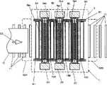
图8表示现有准分子光照射装置的概要图。在准分子光照射装置101中,在灯壳103中并列配置多根圆筒状的准分子灯102。在该灯壳103中,设有上板111和侧板112,该灯壳103下方采用不具有玻璃窗的结构。在该灯壳103内设置的该准分子灯102之间设有具有喷出不活泼气体的喷出口105的不活泼气体流通部104。并且,向该准分子光照射装置101下方传输基板115,利用该准分子灯102放射的准分子光进行清洁处理。并且,在该准分子光照射装置101的灯壳103内设置的该不活泼气体流通部104中,作为不活泼气体流有氮气。该氮气从该喷出口105喷出到该准分子光照射装置101下方,吹到该基板115上。在该准分子光照射装置101下方且在该基板115的周边,通过从该喷出口105喷出的氮气,形成真空紫外区的光可以透过的氧气浓度低的置换空间。FIG. 8 shows a schematic diagram of a conventional excimer light irradiation device. In the excimer light irradiation device 101 , a plurality of cylindrical excimer lamps 102 are arranged in parallel in a lamp housing 103 . In the lamp housing 103, an upper plate 111 and a side plate 112 are provided, and the lower part of the lamp housing 103 adopts a structure without a glass window. Between the excimer lamps 102 provided in the lamp housing 103 is provided an inert gas flow section 104 having a discharge port 105 for discharging an inert gas. Then, the substrate 115 is transported below the excimer light irradiation device 101 , and the excimer light radiated from the excimer lamp 102 is used for cleaning treatment. In addition, nitrogen gas was flowed as an inert gas into the inert gas circulation part 104 provided in the lamp housing 103 of the excimer light irradiation device 101 . The nitrogen gas is ejected from the ejection port 105 to below the excimer light irradiation device 101 , and is blown onto the substrate 115 . Under the excimer photoirradiation device 101 and around the substrate 115, nitrogen gas ejected from the ejection port 105 forms a replacement space with a low oxygen concentration through which light in the vacuum ultraviolet region can pass.
但是,在将氮气吹到该基板115上的现有技术中,存在不活泼气体的使用量很大,不仅制造成本高,并且搬运液晶玻璃基板等时,该基板的前端部、中央及后端部的氧气浓度不均匀,产生处理偏差的问题。并且,在图8所示的现有装置中,也存在该不活泼气体流通部上方的空间不会由氮气等置换,因此吹到基板面上的氮气中卷入的氧气浓度产生较严重的不均匀,还产生与氧气浓度的不均匀相应的严重的处理偏差的问题。However, in the prior art of blowing nitrogen gas onto the substrate 115, there is a large amount of inert gas used, and not only the manufacturing cost is high, but also when the liquid crystal glass substrate and the like are transported, the front end, the center and the rear end of the substrate will be damaged. The oxygen concentration in the part is not uniform, resulting in the problem of processing deviation. In addition, in the conventional device shown in FIG. 8, the space above the inert gas flow part is not replaced by nitrogen gas, etc., so the concentration of oxygen entrapped in the nitrogen gas blown onto the substrate surface has a serious problem. Even, there is also a problem of serious processing variation due to the unevenness of the oxygen concentration.
专利文献1:日本专利公布2001-137800号公报Patent Document 1: Japanese Patent Publication No. 2001-137800
专利文献2:日本专利公布2001-113163号公报Patent Document 2: Japanese Patent Publication No. 2001-113163
专利文献3:日本专利公布2006-134983号公报Patent Document 3: Japanese Patent Publication No. 2006-134983
本发明要解决的问题是提供一种准分子光照射装置,在利用准分子光的液晶面板用玻璃基板等的清洁装置中,即使是未配置大面积的板状玻璃窗的装置,也能使氢气置换时的气体使用量变少。进而,提供一种准分子光照射装置,即使对大型基板进行清洁,也能减少清洁偏差。The problem to be solved by the present invention is to provide an excimer light irradiation device, which can be used even if a large-area plate glass window is not arranged in a cleaning device such as a glass substrate for a liquid crystal panel using excimer light. The amount of gas used in hydrogen replacement is reduced. Furthermore, it is to provide an excimer light irradiation apparatus capable of reducing cleaning variations even when cleaning a large substrate.
发明内容Contents of the invention
本发明的准分子光照射装置,对被搬运的基板照射准分子光,其特征在于:在灯壳内并列配置有多根大致棒状的准分子灯,具有传送基板的搬运装置,在所述灯壳内设有间隔壁部件,在该间隔壁部件和各个准分子灯之间形成狭窄部,在该比灯壳内的该狭窄部靠该准分子灯上方形成第一置换空间,在比该狭窄部靠该准分子灯下方即基板侧形成第二置换空间,在该第一置换空间侧设有喷出包括不活泼气体的气体的喷出口。The excimer light irradiation device of the present invention irradiates excimer light to a substrate being conveyed, and is characterized in that: a plurality of substantially rod-shaped excimer lamps are arranged in parallel in the lamp housing, and a conveying device for transferring the substrate is provided. A partition wall member is provided in the housing, and a narrow portion is formed between the partition wall member and each excimer lamp, and a first replacement space is formed above the excimer lamp at the narrow portion in the lamp housing. A second replacement space is formed at the bottom of the excimer lamp, that is, on the side of the substrate, and an outlet for ejecting gas including an inert gas is provided on the side of the first replacement space.
并且,本发明的准分子光照射装置在所述结构的基础上,其特征在于:所述间隔壁部件兼用作包括不活泼气体的气体流通的喷气管,在该喷气管上,喷出气体的喷出口在该喷气管长边方向上隔开间隔设置。And, the excimer photoirradiation device of the present invention is characterized in that on the basis of the above-mentioned structure: the partition wall member is also used as a gas injection pipe for the flow of gas including an inert gas, and on this gas injection pipe, the flow of the gas is ejected. The ejection ports are arranged at intervals in the longitudinal direction of the air ejection pipe.
进而,所述灯壳具有第一置换空间和第二置换空间,所述第一置换空间由配置在该准分子灯两侧的所述喷气管的各个侧壁、配置在其间的准分子灯的外壁的上表面部分、以及配置在该准分子灯上方的灯壳内的间隔壁形成,所述第二置换空间由所述喷气管的一个下壁、配置在其两侧的准分子灯外壁的下表面部分、以及搬运的基板形成,从该喷气管向该第一置换空间喷出不活泼气体。Furthermore, the lamp housing has a first replacement space and a second replacement space, and the first replacement space is composed of each side wall of the gas injection tube arranged on both sides of the excimer lamp and the excimer lamp arranged therebetween. The upper surface portion of the outer wall and the partition wall arranged in the lamp housing above the excimer lamp are formed, and the second replacement space is formed by a lower wall of the gas injection pipe and the outer walls of the excimer lamp arranged on both sides thereof. The lower surface portion and the transported substrate are formed, and an inert gas is sprayed from the gas injection pipe to the first replacement space.
并且,本发明的准分子光照射装置,在所述结构的基础上,其特征在于:所述第一置换空间的体积大于所述第二置换空间的体积。Furthermore, the excimer photoirradiation device of the present invention is characterized in that, on the basis of the structure, the volume of the first replacement space is larger than the volume of the second replacement space.
进而,本发明的准分子光照射装置,在所述结构的基础上,其特征在于:所述第一置换空间对应于该灯壳内配置的每个准分子灯形成,流入各个置换空间内的气体流量不同。Furthermore, the excimer light irradiation device of the present invention, on the basis of the structure, is characterized in that: the first replacement space is formed corresponding to each excimer lamp arranged in the lamp housing, and the light that flows into each replacement space The gas flow is different.
并且,本发明的准分子光照射装置,在所述结构的基础上,其特征在于:流入所述第一置换空间中的气体流量在该灯壳外侧附近比该灯壳中央附近多。In addition, the excimer light irradiation device of the present invention is characterized in that the gas flow rate flowing into the first replacement space is larger near the outside of the lamp housing than near the center of the lamp housing.
进而,本发明的准分子光照射装置,在所述结构的基础上,其特征在于:在形成该第二置换空间之前,流入所述第一置换空间中的气体流量小于规定量,通过基板的搬运而形成该第二置换空间时,流入所述第一置换空间中的气体流量为预先设定的规定量。Furthermore, the excimer photoirradiation device of the present invention is characterized in that, on the basis of the above structure, the gas flow rate flowing into the first replacement space is less than a predetermined amount before the formation of the second replacement space, and the flow rate of the gas passing through the substrate is When conveying to form the second replacement space, the flow rate of gas flowing into the first replacement space is a predetermined amount set in advance.
并且,本发明的准分子光照射装置,在所述结构的基础上,其特征在于:所述第一置换空间通过传感器检测由基板的搬运而引起的所述第二置换空间的形成或消失,对应于该第二置换空间的形成或消失,控制流入该第一置换空间中的气体流量。In addition, the excimer photoirradiation device of the present invention is characterized in that, on the basis of the above structure, the formation or disappearance of the second replacement space caused by the conveyance of the substrate is detected by the sensor in the first replacement space, Corresponding to the formation or disappearance of the second replacement space, the flow rate of gas flowing into the first replacement space is controlled.
发明效果Invention effect
本发明的准分子光照射装置利用设在灯壳内的间隔壁部件,在该灯壳内设置的准分子灯和该间隔壁部件之间形成狭窄部,由此将该灯壳内的空间两分为第一置换空间和第二置换空间。由此,即使基板侧的第二置换空间由于该基板的搬出而与大气接触,氧气也不会混入该第一置换空间,接着在该基板搬入时,仅在该第二置换空间进行置换即可进行处理。并且,向该第二置换空间的置换将灯壳内的空间分为二份,因此实质的容积变小,置换快速进行,处理速度提高,因此能够减少置换所用的氢气等的气体使用量。进而,在第一置换空间侧设有包括不活泼气体的气体的喷出口,因此能够切实地抑制该第一置换空间的氧气卷入或回流,能够基板处理时实现稳定的氧气浓度。由此具有降低处理偏差的效果。In the excimer light irradiation device of the present invention, a narrow portion is formed between the excimer lamp provided in the lamp housing and the partition wall member by using the partition wall member provided in the lamp housing, whereby the space in the lamp housing is doubled. Divided into the first replacement space and the second replacement space. Thus, even if the second replacement space on the substrate side comes into contact with the atmosphere due to the unloading of the substrate, oxygen will not be mixed into the first replacement space, and then when the substrate is carried in, replacement only needs to be performed in the second replacement space. to process. In addition, since the replacement into the second replacement space divides the space in the lamp housing into two, the actual volume becomes smaller, the replacement proceeds quickly, and the processing speed increases, so the amount of gas used for replacement, such as hydrogen, can be reduced. Furthermore, since the gas ejection port including the inert gas is provided on the side of the first replacement space, entrainment or backflow of oxygen in the first replacement space can be reliably suppressed, and a stable oxygen concentration can be achieved during substrate processing. This has the effect of reducing processing variation.
进而,该间隔壁兼作喷气管,形成在该喷气管上的喷出口在该喷气管的长度方向上隔开间隔设置,因此能够在该准分子灯的灯轴方向上提供均匀的气体流量。并且,通过使置换用气体的喷出方向向着例如相邻的该喷气管的方向即侧面方向,而不是向着基板侧,由此,即使置换用气体缓慢流动,也能在置换所需的空间内进行充分置换。并且,如果该喷出口的设置位置取在该侧面方向,则能够快速排出该第一置换空间内残留的氧气,也能缩短该准分子光照射装置延迟(立ち上り)的时间。Furthermore, the partition wall also serves as a gas injection tube, and the nozzles formed on the gas injection tube are spaced apart in the longitudinal direction of the gas injection tube, so that a uniform gas flow rate can be provided in the lamp axis direction of the excimer lamp. In addition, by making the ejection direction of the replacement gas toward, for example, the direction of the adjacent gas injection pipe, that is, the side surface direction, instead of toward the substrate side, even if the replacement gas flows slowly, it can be replaced within the required space. Make a full replacement. In addition, if the ejection port is located in the side direction, the remaining oxygen in the first replacement space can be quickly discharged, and the delay time of the excimer light irradiation device can also be shortened.
本发明的准分子光照射装置,其灯壳内的空间被分为第一置换空间和第二置换空间,第一置换空间为大致密闭地分隔的空间,不管有无基板,通过从喷气管向第一置换空间喷出的气体而被置换,第二置换空间通过从该第一置换空间溢出的气体而被置换。因此,该基板搬运时能够快速形成适用于准分子灯和该基板之间的清洁的氛围,具有提高清洁效果并降低清洁偏差的效果。In the excimer light irradiation device of the present invention, the space in the lamp housing is divided into a first replacement space and a second replacement space. The first replacement space is a space that is separated in a substantially airtight manner. The gas ejected from the first replacement space is replaced, and the second replacement space is replaced by gas overflowing from the first replacement space. Therefore, when the substrate is transported, an atmosphere suitable for cleaning between the excimer lamp and the substrate can be quickly formed, which has the effect of improving the cleaning effect and reducing cleaning deviation.
进而,该第一置换空间的体积被设置成大于第二置换空间。由此,无论有无基板的搬运(是否形成第二置换空间),第一置换空间都可以稳定地存在。并且,从该第二置换空间侧观察时,与第一置换空间的体积相比,第二置换空间的体积非常小。由此,从该基板被搬入开始经过短时间就可以置换第二置换空间,形成适用于清洁的氛围,因此,具有能够将氮气等置换气体的使用量抑制到非常小的效果。Furthermore, the volume of the first replacement space is set to be larger than that of the second replacement space. Thereby, the first replacement space can stably exist irrespective of whether or not the substrate is conveyed (whether the second replacement space is formed or not). In addition, when viewed from the side of the second replacement space, the volume of the second replacement space is very small compared with the volume of the first replacement space. Thereby, the second replacement space can be replaced in a short time after the substrate is carried in, and an atmosphere suitable for cleaning is created. Therefore, there is an effect that the usage amount of replacement gas such as nitrogen can be suppressed to a very small level.
并且,通过作为被照射物的基板形成关闭的空间,该空间作为第二置换空间,因此不使用大的平板玻璃用作间隔与灯之间的间隔窗部,来自准分子灯的光也能到达该基板,能够提高清洁效果。进而,设置覆盖该准分子灯外周的保护管,在该保护管和该准分子灯之间的空间利用不活泼气体进行置换时,具有如下所述优点:即使在该喷气管流出的不活泼气体中添加反应性气体,也具有能够抑制配置在该准分子灯外表面的网状电极和镜面的劣化、能够高效地将该准分子灯放射的真空紫外线照射到该基板上。In addition, since the closed space is formed by the substrate as the object to be irradiated, this space is used as the second replacement space, so the light from the excimer lamp can also reach without using a large plate glass as the partition window between the partition and the lamp. The substrate can improve the cleaning effect. Furthermore, when a protective tube covering the outer periphery of the excimer lamp is provided, and when the space between the protective tube and the excimer lamp is replaced with an inert gas, it has the following advantages: even if the inert gas flowing out of the jet tube Adding reactive gas to the substrate can also suppress the deterioration of the mesh electrodes and mirrors arranged on the outer surface of the excimer lamp, and can efficiently irradiate the substrate with vacuum ultraviolet rays emitted by the excimer lamp.
并且,在对应于每个该准分子灯形成该第一置换空间,因此在置换气体时可以迅速置换。进而,由于流入各个置换空间的气体流量不同,能够调整处理的基板上的氧气浓度分布,能够进行没有偏差的均匀处理。Also, since the first replacement space is formed corresponding to each of the excimer lamps, replacement of gas can be performed quickly. Furthermore, since the flow rate of gas flowing into each replacement space is different, the oxygen concentration distribution on the substrate to be processed can be adjusted, and uniform processing without variation can be performed.
进而,流入该第一置换空间中的气体流量中,靠近该灯壳外侧的流量比该灯壳中央附近的流量大,由此能够抑制氧气从外部混入。尤其在该基板搬运时,随着该基板的移动,氧气会卷入等,但由于搬入口侧的气体流量较多,因此即使卷入有氧气,也能迅速排出。由此,具有能够以预定的氧气浓度迅速形成第二置换空间的优点。Furthermore, the flow rate of the gas flowing into the first replacement space is larger near the outer side of the lamp housing than near the center of the lamp housing, thereby suppressing the incorporation of oxygen from the outside. In particular, during the transfer of the substrate, oxygen may be entrapped along with the movement of the substrate, but since the flow rate of the gas on the side of the loading port is large, even if oxygen is entrapped, it can be discharged quickly. Thereby, there is an advantage that the second replacement space can be quickly formed at a predetermined oxygen concentration.
并且,在基板被搬运之前,以比该基板处理时少的气体流量抑制氧气侵入该第一置换空间,该基板被搬入时,流入预先设定的规定量的气体,由此具有能够在该第二置换空间确保预定的氧气浓度,消除偏差、均匀且迅速地进行处理的优点。并且,还具有形成第二置换空间所使用的气体使用量减少的优点。In addition, before the substrate is transported, the intrusion of oxygen into the first replacement space is suppressed with a gas flow rate lower than that during the substrate processing, and when the substrate is carried in, a predetermined amount of gas that is set in advance flows in, thereby having the capability of being able to operate in the first replacement space. The second replacement space ensures a predetermined oxygen concentration, eliminates deviation, and has the advantages of uniform and rapid treatment. In addition, there is an advantage that the amount of gas used to form the second replacement space is reduced.
进而,通过传感器检测该基板被搬运的时刻,随着该第二控制空间的形成、消失,控制流入该第一置换空间中的气体流量。由此,将气体使用量最佳化,且能够实现均匀的处理。Furthermore, the time when the substrate is conveyed is detected by the sensor, and the flow rate of the gas flowing into the first replacement space is controlled as the second control space is formed and disappears. Thereby, the amount of gas used is optimized, and uniform treatment can be realized.
附图说明Description of drawings
图1是表示本发明的第一实施例的概要剖视图。Fig. 1 is a schematic sectional view showing a first embodiment of the present invention.
图2是表示本发明的第一实施例中配置的准分子灯的方式的剖视图。Fig. 2 is a cross-sectional view showing the form of an excimer lamp arranged in the first embodiment of the present invention.
图3是表示本发明的第一实施例中配置的喷气管的方式的剖视图。Fig. 3 is a cross-sectional view showing the form of an air injection pipe disposed in the first embodiment of the present invention.
图4是表示本发明的第二实施例的喷气管的方式的剖视图。Fig. 4 is a cross-sectional view showing the form of an air injection pipe according to a second embodiment of the present invention.
图5是表示本发明的第三实施例的概要图。Fig. 5 is a schematic diagram showing a third embodiment of the present invention.
图6是表示本发明的第四实施例的概要图。Fig. 6 is a schematic diagram showing a fourth embodiment of the present invention.
图7是表示本发明的第五实施例的概要图。Fig. 7 is a schematic diagram showing a fifth embodiment of the present invention.
图8是表示现有基板处理装置的概要剖视图。Fig. 8 is a schematic sectional view showing a conventional substrate processing apparatus.
具体实施方式Detailed ways
本发明的准分子光照射装置具有向并列配置有多根准分子灯的灯壳内喷出至少包括氮气的气体的喷气管,具有由该喷气管与该准分子灯上表面部分及该灯壳的间隔壁所包围的第一置换空间、以及该喷气管与该准分子灯下表面部分及搬运的基板所包围的第二置换空间,通过从该喷气管向该第一置换空间喷出不活泼气体,形成该第一置换空间。并且,通过使该第二置换空间的体积小于该第一置换空间,在利用氮气等置换该基板侧的氛围时,能够高效进行置换,能够在短时间内高效进行该基板的处理。The excimer photoirradiation device of the present invention has a jet pipe for ejecting gas including nitrogen at least into a lamp housing in which a plurality of excimer lamps are arranged side by side, and has The first replacement space surrounded by the partition wall, and the second replacement space surrounded by the gas injection tube, the lower surface part of the excimer lamp and the transported substrate, by spraying inert gas from the gas injection tube to the first replacement space gas, forming the first replacement space. Furthermore, by making the volume of the second replacement space smaller than that of the first replacement space, when the atmosphere on the substrate side is replaced with nitrogen gas or the like, the replacement can be efficiently performed, and the substrate can be processed efficiently in a short time.
第一实施例first embodiment
作为第一实施例,图1表示本发明的准分子光照射装置。图1-a)是以垂直于多根并列配置的大致棒状的准分子灯2的管轴方向的面切断的准分子光照射装置1的概要剖视图。在该准分子光照射装置1中,多根准分子灯2在灯壳3内并列配置。在该灯壳3内,多根准分子灯2并列配置。在该灯壳3内设有间隔壁4,该间隔壁4上并列配置多根喷出包括氮气等不活泼气体的气体的喷气管5,在该喷气管之间配置该准分子灯2。并且,以各喷气管5与该准分子灯2之间形成狭窄部8的方式配置在该灯壳3内。在该间隔壁4的上方设有冷却块6,在该冷却块6内配置流过冷却流体的冷却流体通路6a,在该冷却块6上方设有向该准分子灯2供电的产生高频高压的电装部7。并且,在该准分子灯2下方,作为搬运被处理物基板10的搬运系统,使用辊带11,作为该基板10,例如可以将液晶面板用的玻璃基板等搬运到该准分子光照射装置1内。As a first embodiment, FIG. 1 shows an excimer light irradiation device of the present invention. 1-a) is a schematic cross-sectional view of the excimer
并且,在该喷气管5中,多个喷出包括氮气等不活泼气体的气体的喷出口9在长边方向上以大致等间隔设置,设置在该喷气管5的侧壁5a上,从该喷气管5向第一置换空间喷出气体。进而,在该喷气管5上设有气体导入口42,从该气体导入口42经由控制阀74,与气体供给源连接。In addition, in the
并且,该准分子光照射装置1具有第一置换空间13和第二置换空间14。在图1-b)中,为了对第一置换空间13和第二置换空间14进行说明,表示仅将该第一置换空间13和该第二置换空间14的部分示意性放大的放大图。该第一置换空间13是由相对的该喷气管5的侧壁5a、该准分子灯2的上表面部分2a以及该灯壳3的间隔壁4所包围的部分构成的空间,该喷气管5和该准分子灯2之间的狭窄部8由以最短距离横穿该喷气管5和该准分子灯2的假想线划分。另一方面,第二置换空间14是该喷气管5的下壁5b、配置在其两侧的准分子灯2的下表面部分2b及被搬运的基板10所包围的部分构成的空间,该喷气管5和该准分子灯2之间的狭窄部8由以最短距离横穿该喷气管5和该准分子灯2的假想线划分,该准分子灯2与该基板10间的间隙由以最短距离连接该准分子灯2的下表面部分2b和该基板10的假想线15划分。在本发明中,该第二置换空间14的体积小于该第一置换空间13的体积。并且,此处的体积是指,图1-b)所示的剖视图中的面积乘以该准分子灯2的管轴方向的长度(到未图示的侧面间隔板为止的长度)而得到的体积。Furthermore, this
通过这种结构,能够形成适用于清洁该准分子灯2和该基板10之间的氛围,具有提高清洁效果并且降低清洁偏差的效果。尤其是通过使该第二置换空间的体积形成得比该第一置换空间的体积小很多,从该基板10被搬入开始,在短时间内,置换第二置换空间,能够形成适用于清洁的氛围,因此,还具有例如氮气等置换气体的使用量被抑制为非常小的效果。Through this structure, an atmosphere suitable for cleaning between the
接着,作为图2,表示第一实施例所示的该准分子光照射装置1所具有的准分子灯2。图2是沿着该准分子灯2的管轴方向切断的管轴方向剖视图,该准分子灯2由发光管部21、外管部22以及灯头部23构成。该发光管部21由石英玻璃构成的灯泡部24;配置在该灯泡部24外周的网状电极25;与该网状电极25成对的内部电极26;以及在该灯泡部24内以包围该内部电极26的方式配置的石英玻璃构成的内部管27构成。进而,在该灯泡部24内,作为准分子发光用气体例如封入有氙气。该内部电极26的端部与供电销28连接,该供电销28的另一端与钼构成的金属箔29连接,在该灯泡部24两端夹紧密封。并且,该金属箔29的另一端与外部导线30连接,从外部向该内部电极26供给高频高压。与该内部电极26成对的该网状电极25通过配置在该灯头部23的供电部31接地。Next, as FIG. 2 , the
该发光管部21在该内部电极26和该网状电极25之间经由该灯泡部24和该内部管27这两个电介体施加高频高压,由此,封入在该灯泡部24内部的氙气发生准分子放电,通过受激准分子的生成、分解,产生准分子光。并且,外管部22也由石英玻璃构成,作为该发光管部21发出的光(是氙气的情况下为波长172nm的真空紫外线)从该外管部22向外部放射的窗而起作用。并且,在设在该发光管部21和该外管部22之间的空间中充满氮气,从该发光管部21放射的真空紫外线不会接受氧气的吸收而衰减地放射到该外管部22的外部。The
并且,在该发光管部21及该外管部22的两端设有该灯头部23,保持该发光管部21和该外管部22。该发光管部21插入固定在该灯头部23内的保持用凸缘部32内,直至该网状电极25的端部部分。进而,在该灯头部23中央设有供电线取出用孔33,向该发光管部21供电的供电线34从该供电线取出用孔33取出到外部。进而,设有使该外管部22内充满的氮气流入、排出的气体流通口35。Furthermore, the base portion 23 is provided at both ends of the
通过将这种结构的准分子灯2配置在该准分子光照射装置1上,具有即使不设置大型的平板玻璃窗,也能高效取出从该准分子灯2放射的真空紫外线的优点。进而,该保护管的形状为圆筒状,因此具有即使该保护管的壁厚较薄,也能得到足够的机械强度,不会由于保护管的厚度引起照度降低,能够得到高效的照射装置的优点。并且,由于该保护管自身涉及的成本比大型平板玻璃便宜很多,因此还具有将装置整体价格降低的优点。By arranging the
接着,作为图3,表示第一实施例所示的该准分子光照射装置1所具有的喷气管5。图3-a)是沿着该喷气管5的管轴方向切断的管轴方向的剖视图,图3-b)是以垂直于图3-a)的该管轴方向的面切断的A-A截面的剖视图。在图3-a)中,在该喷气管5的侧壁5a上设有多个喷出气体的小孔的喷出口9。并且,在该喷气管5的上表面壁5c侧,设有向该喷气管5供给气体的气体导入口42。在图3-b)中,该喷气管5的A-A截面为长方形,例如该上表面壁5c、及该下壁5b的长度为20mm,该侧壁5a的长度为30mm。并且,设在该侧壁5a上的该喷出口9为φ0.7mm的圆形,从该喷出口9中心到中心的距离以10mm间距形成在该侧壁5a上。例如,如果该喷气管5的全长为2m,在一个该侧壁5a上形成200个该喷出口9。并且,在本实施例的该喷气管5中,该喷气管5的截面积s(该侧壁5a的长度×该下壁5b的长度)为该喷出口9的总面积(例如φ0.7的面积×200(个数))的2.5倍以上的大小。通过具有这样的面积比,喷出的气体的流速在各个喷出口9变得均匀。Next, as FIG. 3 , the
通过采用这种结构,从该喷气管5喷出的气体在该喷气管5整体上均匀地喷出,能够均匀地保持装置整体的氛围。其结果是得到如下效果:该准分子光照射装置1可以在对该基板10进行清洁处理时保持均匀的气体氛围,能够进行没有偏差的清洁处理。并且,通过极力缩小该第二置换空间的体积,能够在该基板搬运时,在短时间内置换为处理氛围,能够充分抑制从外部卷入氧气,因此还具有氮气等不活泼气体的使用量变少的优点。By adopting such a configuration, the gas ejected from the
例如,在本实施例的情况下,第二置换空间的体积大约为100cm-3(容积大致为1L),从该喷气管流过来的氮气的流量为25L/分左右。在该情况下,从基板被搬运开始,大约以2.4秒完成置换。并且,置换完成时的残留氧气浓度实现200ppm左右的非常低的值。通常,置换时的残留氧气浓度为1000ppm左右即足够,如果不考虑置换所需要的时间,对于容积1L,如果是13L/分左右的气体流量,残留氧气浓度可以实现1000ppm以下。For example, in the case of this embodiment, the volume of the second replacement space is about 100 cm−3 (volume is about 1 L), and the flow rate of the nitrogen gas flowing from the jet pipe is about 25 L/min. In this case, the replacement is completed in about 2.4 seconds from the time the substrate is conveyed. In addition, the residual oxygen concentration at the time of completion of the replacement is very low at around 200 ppm. Usually, a residual oxygen concentration of about 1000ppm is sufficient during replacement. If the time required for replacement is not considered, for a volume of 1L, if the gas flow rate is about 13L/min, the residual oxygen concentration can be achieved below 1000ppm.
第二实施例second embodiment
图4是作为本发明的第二实施例,表示其他该气体喷气管的形状的剖视图。图4-a)所示的喷气管51中,为了喷出气体而设置的喷出口的形状从该喷气管51的长边方向端部开始分别按照喷出口9a、9b、9c、9d的顺序,孔径减小。通过采用这种结构,从该喷气管51喷出的气体的流量在该喷气管51的长边方向上不同,与该喷气管51中央附近相比,端部附近喷出的气体的流量变多。通过将该喷气管51组装入本发明的准分子光照射装置中,与该准分子光照射装置的灯壳的该准分子灯管轴方向中央附近相比,可以使流至该灯壳外侧附近的流量变多。这具有能够降低从准分子光照射装置外部卷入的不能控制的氧气混入的优点。Fig. 4 is a cross-sectional view showing another shape of the gas injection pipe as a second embodiment of the present invention. Figure 4-a) in the
图4-b)所示的喷气管52中,为了喷出气体而设置的喷出口的孔径相同,但从该喷气管52的长边方向的端部侧开始逐渐改变排列间隔,在该端部侧设置得较密,在中央部侧设置得较疏。具体来说,从中央部开始,喷出口9A、9B、9C、9D的孔与孔的间隔53逐渐变窄。通过采用这种结构,与该喷气管52的中央附近相比,端部附近喷出的气体的流量也可以变多。与该喷气管51的情况同样地,将该喷气管52组装入本发明的准分子光照射装置,由此与该准分子光照射装置的灯壳的该准分子灯管轴方向中央附近相比,可以使流至该灯壳外侧附近的气体的流量变多。这具有能够降低从准分子光照射装置外部卷入的不能控制的氧气混入的优点。并且,通过将喷出口的排列和孔径排列在任意位置上,也可以形成具有所希望的氧气浓度分布的处理空间。In the
第三实施例third embodiment
图5表示本发明的第三实施例。在该第三实施例中,表示使流入该第一置换空间中的气体流量为对应每个该准分子灯形成的每个第一置换空间中的不同流量的情况。图5所示的该准分子光照射装置1是从该装置上方观察并列配置有3根准分子灯2A、2B、2C的该准分子光照射装置1的灯壳内的图。并且,表示了在该准分子光照射装置1以外并列多根辊带11构成的传送路径、和在该传送路径上向箭头63的方向搬运基板10的状态。该基板10从该准分子光照射装置1的搬运口62A搬入,从搬出口62B搬出。在从该搬运口62A到搬出口62B之间,准分子灯2A、2B、2C相互并列配置,在各个准分子灯2A、2B、2C两侧面上配置有喷气管5A、5B、5C、5D。例如,在准分子灯2A的两侧面上配置有喷气管5A和喷气管5B,形成与各个准分子灯2A、2B、2C对应的第二置换空间13A、13B、13C。并且,该第一置换空间13A、13B、13C在该准分子灯2A、2B、2C的管轴方向上,由侧面间隔板61间隔开,向由该侧面间隔板61、该喷气管5A、5B、5C、5D与该准分子灯2A、2B、2C所间隔开的空间中流入氮气等置换用气体。Fig. 5 shows a third embodiment of the present invention. In the third embodiment, a case is shown in which the flow rate of gas flowing into the first replacement space is different in each first replacement space formed corresponding to each excimer lamp. The excimer
作为流入该第一置换空间13A、13B、13C的气体流量,在基板10的搬入口62A侧(13A)流量变多,在中央附近(13B)减少,再次在该基板10的搬出口62B侧(13C)流量变多。在本实施例中,该喷气管5A内的气压高于相邻喷气管5B,并且相对的喷气管5B的该第一置换空间13A侧的侧壁5ab上的喷出口(未图示)的孔径比另一侧壁5ac上的喷出口(未图示)的孔径大。由此,流至该第一置换空间13A侧的气体量多于相邻第一置换空间13B。As the flow rate of gas flowing into the
接着,对于该第一置换空间13B,由于分别设在该喷气管5B的侧壁5ac、该喷气管5C的侧壁5ad上的喷出口(未图示)的孔径比设在相邻第一置换空间13A或13C侧的孔径小,因此流入该第一置换空间13B的气体的流量变小。进而,该第一置换空间13C与该第一置换空间13A的情况相同。即,该喷气管5C的该第一置换空间13C侧的侧壁5ae上设置的喷出口(未图示)的孔径与侧壁5ab相同。进而,该喷气管5D上设置的喷出口的孔径与该喷气管5A相同,施加在该喷气管5D上的气压也与该喷气管5A为相同程度,比该喷气管5B、5C的气压高。通过这种结构,第一置换空间13A、13B、13C的气体流量在该灯壳外侧附近比灯壳中央附近多。Next, for the
第四实施例Fourth embodiment
图6表示作为本发明的第四实施例,具有对流入该第一置换空间13和该第二置换空间14中的流量进行控制的机构的该准分子光照射装置1。该准分子光照射装置1在灯壳3内配置有多根并列配置的准分子灯2、在该准分子灯2两侧面并列配置的喷气管5、以及具有将从该准分子灯2放射的光向基板10侧反射的功能的间隔壁4。在本实施例中,仅记载了该灯壳3的一部分。并且,从将基板10搬入该准分子光照射装置1的搬运口62A侧,基板10的一部分通过辊带11被搬运到该准分子光照射装置1内。在该辊带11下方依次配置有光传感器71A、71B、71C、71D。来自该光传感器71A、71B、71C、71D的信号与信号处理部72连接。输入到该信号处理部72的该光传感器71A、71B、71C、71D的信号与控制信号输出部73连接,从该控制信号输出部73输入到控制阀74A、74B、74C、74D。该控制阀74A、74B、74C、74D与该喷气管5连接,控制置换用气体的气体流量和气压,形成该第一置换空间13A、13B、13C、13D以及该第二置换空间14A、14B等。并且,14C、14D由于处在搬运基板10的中途,因此处于形成第二置换空间前的状态,是随着该基板10的搬运而形成第二置换空间的区域。FIG. 6 shows the
接着,表示气体流量的控制。最初是在该准分子光照射装置1内没有处理对象基板的状态。此时,该第一置换空间13A、13B、13C、13D的各个空间中流入比预先设定的基板处理时的规定量少的量的置换用气体。接着,该基板10搬入该准分子光照射装置1内时,通过该光传感器71A,检测到该基板10被搬入,检测信号被输入到信号处理部72,接着从控制信号输出部73向箭头Q和R送出控制气体流量的信号。接收到该控制信号的控制阀74A、74B将流入该第一置换空间13A中的气体流量增加到预先设定的基板处理时的规定量。由此能够在极短时间内,形成该第二置换空间14A,形成适于预先设定的该基板10的处理的氛围。Next, control of the gas flow rate will be described. Initially, there is no substrate to be processed in the excimer
如图6所示,在基板10搬运到该第二置换空间14C中途的状态下,各空间的气体流量如下。该第二置换空间14A、14B中流入预先设定的基板处理时的规定量的气体。在该第二置换空间14C中,在该光传感器71C检测到该基板10的搬运之后,马上将流入该第二置换空间14C的气体量控制成小于相邻的该第二置换空间14B。并且,同样地,在将成为该第二置换空间14D的空间中,由于没有基板10被搬运,因此在该光传感器71D检测到该基板10的搬入之前,流入比第二置换空间14A、14B少量的置换用气体。As shown in FIG. 6 , in the state where the
通过采用这种控制机构,在形成第二置换空间之前,流入比规定量少量的气体,仍然保持第一置换空间的氛围,能够减少来自外部的氧气等的混入。并且,检测到基板10搬入,使气体流量增加,流入适用于预定的处理的规定量气体。随之,形成该第二置换空间,流入最适用于处理的流量,由此能够高效地处理该基板10。并且,该基板被搬出,该第二置换空间消失时,再次流入小于规定量的气体,由此能够一边防止来自外部的氧气混入,一边待机,在下一次搬入处理的基板时,能够在短时间内形成处理氛围。By adopting such a control mechanism, before forming the second replacement space, a smaller amount of gas is flowed in than a predetermined amount, and the atmosphere of the first replacement space is maintained, thereby reducing the incorporation of oxygen or the like from the outside. Then, when the loading of the
图7表示本发明的第五实施例。作为第五实施例的准分子光照射装置81表示在垂直于准分子灯2的灯管轴方向的方向上切断的剖视图。在灯壳3内设有间隔壁部件82,多根该准分子灯2并列配置,在各个准分子灯2和该间隔壁部件82之间形成狭窄部83。并且,在该准分子灯2上方设有具有冷却流体流通路径6a的冷却块6。在该冷却块6上方配置有电装部7。并且,在该冷却块6上具有向该准分子灯2侧的空间喷出包括不活泼气体的气体的喷出口82,该喷出口82经由控制阀74从连接的气体供给源喷出氮气等气体。该准分子灯2上方由该间隔壁部件82和该准分子灯2包围的空间形成第一置换空间13。并且,该准分子灯2下方的基板10侧的空间成为第二置换空间14。该第二置换空间14是由该准分子灯2与该基板10及该间隔壁部件82包围的空间,通过该狭窄部83与该第一置换空间分开。Fig. 7 shows a fifth embodiment of the present invention. The excimer
本实施例的准分子光照射装置81在第一置换空间13内设置喷出包括不活泼气体的气体(本情况下为氮气)的喷出口84,因此第一置换空间最先被置换。其后,充满在该第一置换空间13内的置换用气体(氮气)通过狭窄部83,流到第二置换空间14。通过该漏出的气体形成第二置换空间14。并且,第二置换空间14通过利用辊带11搬入基板10而形成,通过基板被搬出而消失。消失时形成该第二置换空间14的空间暴露在大气中,但该狭窄部83抑制氧气向第一置换空间回流或卷入。并且,在该基板10被搬入之前的待机时,向该第一置换空间13内流入比基板处理时少量的置换用气体(氮气),由此能够维持该第一置换空间13。In the
Claims (8)
Applications Claiming Priority (3)
| Application Number | Priority Date | Filing Date | Title |
|---|---|---|---|
| JP2006246405AJP2008068155A (en) | 2006-09-12 | 2006-09-12 | Excimer light irradiation equipment |
| JP2006246405 | 2006-09-12 | ||
| JP2006-246405 | 2006-09-12 |
Publications (2)
| Publication Number | Publication Date |
|---|---|
| CN101199923A CN101199923A (en) | 2008-06-18 |
| CN101199923Btrue CN101199923B (en) | 2011-08-17 |
Family
ID=39290225
Family Applications (1)
| Application Number | Title | Priority Date | Filing Date |
|---|---|---|---|
| CN2007101496663AExpired - Fee RelatedCN101199923B (en) | 2006-09-12 | 2007-09-10 | Excimer light irradiation apparatus |
Country Status (4)
| Country | Link |
|---|---|
| JP (1) | JP2008068155A (en) |
| KR (1) | KR20080024062A (en) |
| CN (1) | CN101199923B (en) |
| TW (1) | TW200814185A (en) |
Families Citing this family (8)
| Publication number | Priority date | Publication date | Assignee | Title |
|---|---|---|---|---|
| JP5195111B2 (en)* | 2008-07-17 | 2013-05-08 | ウシオ電機株式会社 | Excimer lamp device |
| JP5083184B2 (en)* | 2008-11-26 | 2012-11-28 | ウシオ電機株式会社 | Excimer lamp device |
| JP5051160B2 (en)* | 2009-03-17 | 2012-10-17 | ウシオ電機株式会社 | UV irradiation equipment |
| DE102015011177B4 (en) | 2015-08-27 | 2017-09-14 | Süss Microtec Photomask Equipment Gmbh & Co. Kg | Device for applying a liquid medium exposed to UV radiation to a substrate |
| DE102017203351B4 (en)* | 2017-03-01 | 2021-08-05 | Süss Microtec Photomask Equipment Gmbh & Co. Kg | Device for applying a liquid medium exposed to UV radiation to a substrate |
| JP6984206B2 (en)* | 2017-07-19 | 2021-12-17 | ウシオ電機株式会社 | Light irradiation device |
| CN110787978B (en)* | 2019-11-04 | 2024-01-02 | 广东瀚秋智能装备股份有限公司 | Super-matte machine |
| CN117718276A (en)* | 2023-12-15 | 2024-03-19 | 西安奕斯伟材料科技股份有限公司 | Cleaning device |
Citations (2)
| Publication number | Priority date | Publication date | Assignee | Title |
|---|---|---|---|---|
| CN1353029A (en)* | 2000-11-09 | 2002-06-12 | 财团法人工业技术研究院 | Method for Fabricating Microsphere and Aspheric Polymer Structure Arrays Using Excimer Laser |
| CN1553477A (en)* | 2003-07-16 | 2004-12-08 | 友达光电股份有限公司 | Laser crystallization system and method for controlling energy density of excimer laser annealing process |
Family Cites Families (2)
| Publication number | Priority date | Publication date | Assignee | Title |
|---|---|---|---|---|
| JP2001300451A (en)* | 2000-04-25 | 2001-10-30 | Hoya Schott Kk | Ultraviolet irradiation device |
| TWI251506B (en)* | 2000-11-01 | 2006-03-21 | Shinetsu Eng Co Ltd | Excimer UV photo reactor |
- 2006
- 2006-09-12JPJP2006246405Apatent/JP2008068155A/enactivePending
- 2007
- 2007-07-18TWTW096126194Apatent/TW200814185A/enunknown
- 2007-08-08KRKR1020070079459Apatent/KR20080024062A/ennot_activeCeased
- 2007-09-10CNCN2007101496663Apatent/CN101199923B/ennot_activeExpired - Fee Related
Patent Citations (2)
| Publication number | Priority date | Publication date | Assignee | Title |
|---|---|---|---|---|
| CN1353029A (en)* | 2000-11-09 | 2002-06-12 | 财团法人工业技术研究院 | Method for Fabricating Microsphere and Aspheric Polymer Structure Arrays Using Excimer Laser |
| CN1553477A (en)* | 2003-07-16 | 2004-12-08 | 友达光电股份有限公司 | Laser crystallization system and method for controlling energy density of excimer laser annealing process |
Non-Patent Citations (1)
| Title |
|---|
| JP特开2000-241390A 2000.09.08 |
Also Published As
| Publication number | Publication date |
|---|---|
| KR20080024062A (en) | 2008-03-17 |
| JP2008068155A (en) | 2008-03-27 |
| CN101199923A (en) | 2008-06-18 |
| TW200814185A (en) | 2008-03-16 |
Similar Documents
| Publication | Publication Date | Title |
|---|---|---|
| CN101199923B (en) | Excimer light irradiation apparatus | |
| KR100677661B1 (en) | Ultraviolet Light Irradiation Apparatus and Method | |
| TWI390552B (en) | Excimer lamp device | |
| US6379024B1 (en) | Dielectric barrier excimer lamp and ultraviolet light beam irradiating apparatus with the lamp | |
| CN103128080B (en) | Light irradiation device | |
| CN100521097C (en) | ultraviolet washing device and washing method | |
| KR100733803B1 (en) | Excimer ultraviolet photoreactor | |
| KR20090096307A (en) | Ultraviolet irradiation unit and ultraviolet irradiation processing apparatus | |
| JP2008041998A (en) | Substrate drying apparatus and substrate drying method | |
| JP5077173B2 (en) | UV irradiation treatment equipment | |
| JP6550964B2 (en) | Optical processing apparatus and manufacturing method thereof | |
| KR101553735B1 (en) | Light irradiation apparatus | |
| TWI416584B (en) | Ultraviolet radiation treatment device | |
| JP5600871B2 (en) | Excimer lamp device | |
| JP2011243913A (en) | Ultraviolet treatment device and ultraviolet irradiation device | |
| JP2001219053A (en) | Oxidation method using dielectric barrier discharge and oxidation treatment apparatus | |
| JP4883133B2 (en) | UV light cleaning equipment | |
| JP2004119942A (en) | Ultraviolet irradiation device | |
| JP4645781B2 (en) | Substrate processing method and substrate processing apparatus | |
| JP2001155684A (en) | Dielectric barrier excimer lamp | |
| JP2004113984A (en) | Ultraviolet irradiator | |
| TWI569300B (en) | Lighting device | |
| JP2006310682A (en) | Substrate processing apparatus | |
| JP5093176B2 (en) | Excimer lamp device | |
| JP2002263596A (en) | Ultraviolet irradiation device |
Legal Events
| Date | Code | Title | Description |
|---|---|---|---|
| C06 | Publication | ||
| PB01 | Publication | ||
| C10 | Entry into substantive examination | ||
| SE01 | Entry into force of request for substantive examination | ||
| C14 | Grant of patent or utility model | ||
| GR01 | Patent grant | ||
| CF01 | Termination of patent right due to non-payment of annual fee | ||
| CF01 | Termination of patent right due to non-payment of annual fee | Granted publication date:20110817 |