CN101199114A - Piezoelectric resonator plate and piezoelectric resonator - Google Patents
Piezoelectric resonator plate and piezoelectric resonatorDownload PDFInfo
- Publication number
- CN101199114A CN101199114ACNA2006800219065ACN200680021906ACN101199114ACN 101199114 ACN101199114 ACN 101199114ACN A2006800219065 ACNA2006800219065 ACN A2006800219065ACN 200680021906 ACN200680021906 ACN 200680021906ACN 101199114 ACN101199114 ACN 101199114A
- Authority
- CN
- China
- Prior art keywords
- base portion
- base
- electrode
- zone
- oscillating
- Prior art date
- Legal status (The legal status is an assumption and is not a legal conclusion. Google has not performed a legal analysis and makes no representation as to the accuracy of the status listed.)
- Pending
Links
Images


Classifications
- H—ELECTRICITY
- H03—ELECTRONIC CIRCUITRY
- H03H—IMPEDANCE NETWORKS, e.g. RESONANT CIRCUITS; RESONATORS
- H03H9/00—Networks comprising electromechanical or electro-acoustic elements; Electromechanical resonators
- H03H9/15—Constructional features of resonators consisting of piezoelectric or electrostrictive material
- H03H9/21—Crystal tuning forks
- H03H9/215—Crystal tuning forks consisting of quartz
- H—ELECTRICITY
- H03—ELECTRONIC CIRCUITRY
- H03H—IMPEDANCE NETWORKS, e.g. RESONANT CIRCUITS; RESONATORS
- H03H9/00—Networks comprising electromechanical or electro-acoustic elements; Electromechanical resonators
- H03H9/02—Details
- H03H9/05—Holders or supports
- H03H9/10—Mounting in enclosures
- H03H9/1007—Mounting in enclosures for bulk acoustic wave [BAW] devices
- H03H9/1014—Mounting in enclosures for bulk acoustic wave [BAW] devices the enclosure being defined by a frame built on a substrate and a cap, the frame having no mechanical contact with the BAW device
- H03H9/1021—Mounting in enclosures for bulk acoustic wave [BAW] devices the enclosure being defined by a frame built on a substrate and a cap, the frame having no mechanical contact with the BAW device the BAW device being of the cantilever type
Landscapes
- Physics & Mathematics (AREA)
- Acoustics & Sound (AREA)
- Chemical & Material Sciences (AREA)
- Crystallography & Structural Chemistry (AREA)
- Piezo-Electric Or Mechanical Vibrators, Or Delay Or Filter Circuits (AREA)
Abstract
Description
Translated fromChinese技术领域technical field
本发明涉及压电谐振板和压电谐振器,更为具体的,涉及压电谐振板的构造。The present invention relates to a piezoelectric resonant plate and a piezoelectric resonator, and more specifically, relates to the structure of the piezoelectric resonant plate.
背景技术Background technique
压电振荡装置包括,使用由基部和具有从该基部伸出的两个分叉的振荡部构成的音叉晶体振荡极板的音叉晶体振荡器(例如,参见专利文献1)。该音叉晶体谐振器用于电子装置、便携终端等以提供精确的时钟频率。Piezoelectric oscillation devices include a tuning-fork crystal oscillator using a tuning-fork crystal oscillation plate composed of a base and an oscillating portion having two branches protruding from the base (for example, see Patent Document 1). The tuning fork crystal resonator is used in electronic devices, portable terminals, etc. to provide precise clock frequencies.
上述音叉晶体谐振器具有由基座和盖子构成的外壳,在该外壳内,气密地密封着由导电接合部件接合并支撑在基座上的音叉晶体谐振板。导电接合部件使用例如导电粘合剂。通过使用导电粘合剂将音叉晶体谐振板的基部与基座接合起来,从而使音叉晶体谐振器中的激励电极与设在基座中的焊盘电极之间电导通。The tuning-fork crystal resonator described above has a case composed of a base and a cover, and the tuning-fork crystal resonator plate supported on the base and joined by a conductive joining member is hermetically sealed in the case. As the conductive joining member, for example, a conductive adhesive is used. The base of the tuning fork crystal resonator plate is bonded to the base by using a conductive adhesive, so that the excitation electrodes in the tuning fork crystal resonator are electrically connected to the pad electrodes provided in the base.
专利文献1给出了一种结构,其中音叉晶体谐振板的基部设置有开槽。该专利文献公开了该结构减弱了分叉部的振动向基部一侧泄漏,并通过增强约束振荡能量效应降低了CI值(晶体阻抗)。
专利文献1:JP2004-260718A。Patent Document 1: JP2004-260718A.
但是,在专利文献1中所述的音叉晶体谐振器中,随着音叉晶体谐振板的尺寸进一步缩小,其趋势为基部进一步缩小。特别是,当基部区域进一步缩小(尤其是基部区域的长度缩短)时,不仅不能得到良好地约束振荡能量的效果,而且在基部区域内难以获得导电接合部件用的有效接合区域,因而存在对诸如音叉晶体谐振器基座的连接目标的接合强度降低的问题。However, in the tuning fork crystal resonator described in
为了解决上述问题,本发明的目的为提供一种压电谐振板和压电谐振器,具有高度的可靠性并且由此可以在不降低压电谐振板的接合强度的前提下减小压电谐振板的尺寸,以及CI值(晶体阻抗)可以通过约束振荡能量效应的增强而得到降低。In order to solve the above-mentioned problems, an object of the present invention is to provide a piezoelectric resonator plate and a piezoelectric resonator which have high reliability and thereby can reduce piezoelectric resonance without lowering the joint strength of the piezoelectric resonator plate. The size of the plate, as well as the CI value (crystal impedance) can be reduced by enhancing the effect of confined oscillation energy.
发明内容Contents of the invention
为了达到该目的,本发明的压电谐振板包括基部和振荡部,振荡部具有从基部伸出的多个分叉部。每个分叉部设置有:具有不同电势的激励电极;和连接至激励电极的引线电极,以便将激励电极电连接至外部电极。在基部中至少具有两个导电接合部件形成区域,用于将引线电极的一部分通过导电接合部件接合至外部电极。基部以宽于振荡部的方式形成,并且具有基部中央区域和基部拓宽区域,基部中央区域具有与振荡部相同的宽度,振荡部从基部中央区域延伸;基部拓宽区域沿振荡部的侧边延伸出来,并限定导电接合部件形成区域。从位于基部中央区域和基部拓宽区域之间的基部的边界角部开始的伸长的薄壁部分形成于基部内。To achieve this object, a piezoelectric resonance plate of the present invention includes a base and an oscillating portion having a plurality of branched portions protruding from the base. Each bifurcation is provided with: excitation electrodes having different potentials; and lead electrodes connected to the excitation electrodes so as to electrically connect the excitation electrodes to external electrodes. There are at least two conductive bonding member forming regions in the base portion for bonding a part of the lead electrode to the external electrode through the conductive bonding member. the base portion is formed wider than the vibrating portion, and has a base central region having the same width as the vibrating portion, and a base widening region extending from the base central region; and a base widening region extending along sides of the vibrating portion , and define a conductive bonding feature forming region. An elongated thin-walled portion is formed within the base from a bordering corner of the base between the base central region and the base widening region.
根据本发明,基部以宽于振荡部的方式形成并且具有基部中央区域和基部拓宽区域,薄壁部分形成于基部内,从而产生于振荡部的振荡能量的传输被基部拓宽区域减弱并由开始于位于基部中央区域和基部拓宽区域之间的基部的边界角部的薄壁部分有效阻挡。因此,可以在实现基部尺寸减小的同时减少从振荡部向每个导电接合部件形成区域的振荡泄漏。另外,由于开始于位于基部中央区域和基部拓宽区域之间的基部的边界角部的延长的薄壁部分得以形成,可以在不增加压电谐振板的基部长度的同时有效在基部拓宽区域内有效布置导电接合部件形成区域,同时不会降低压电谐振板的接合强度。此外,由于薄壁部分得到延长,压电谐振板的基部的刚性不被降低,不会出现压电谐振板破损或者类似情形。According to the present invention, the base portion is formed wider than the oscillating portion and has a base central region and a base widening region, and a thin-walled portion is formed in the base so that transmission of oscillation energy generated from the oscillating portion is weakened by the base widening region and started from The thin-walled portions at the boundary corners of the base between the base central region and the base widening region effectively block. Therefore, it is possible to reduce oscillation leakage from the oscillating portion to each conductive bonding member forming region while achieving reduction in size of the base portion. In addition, since the elongated thin-walled portion is formed from the boundary corner of the base between the base central area and the base widening area, it is possible to effectively operate within the base widening area without increasing the base length of the piezoelectric resonance plate. The conductive bonding member forming region is arranged without reducing the bonding strength of the piezoelectric resonance plate. Furthermore, since the thin-walled portion is extended, the rigidity of the base of the piezoelectric resonance plate is not lowered, and breakage of the piezoelectric resonance plate or the like does not occur.
另外,本发明的压电谐振板包括基部和具有从基部伸出的多个分叉部的振荡部。每个分叉部设置有:具有不同电势的激励电极;和连接至激励电极的引线电极,以便将激励电极电连接至外部电极。在基部内至少具有两个导电接合部件形成区域,用于将引线电极的一部分通过导电接合部件接合至外部电极。基部以宽于振荡部的方式形成,并且具有基部中央区域和基部拓宽区域,基部中央区域具有与振荡部相同的宽度,振荡部从基部中央区域延伸;基部拓宽区域沿振荡部的侧边延伸出来并限定导电接合部件形成区域。在基部中,形成从基部拓宽区域的延伸出分叉部的一侧的角部开始的伸长的薄壁部分。In addition, the piezoelectric resonance plate of the present invention includes a base and an oscillating portion having a plurality of branched portions protruding from the base. Each bifurcation is provided with: excitation electrodes having different potentials; and lead electrodes connected to the excitation electrodes so as to electrically connect the excitation electrodes to external electrodes. There are at least two conductive bonding member forming regions in the base portion for bonding a part of the lead electrode to the external electrode through the conductive bonding member. the base portion is formed wider than the vibrating portion, and has a base central region having the same width as the vibrating portion, and a base widening region extending from the base central region; and a base widening region extending along sides of the vibrating portion And the conductive bonding member formation area is defined. In the base, an elongated thin-walled portion is formed from a corner of a side of the base widening region extending from the bifurcation.
根据本发明,基部以宽于振荡部的方式形成并且具有基部中央区域和基部拓宽区域,薄壁部分形成于基部内,从而产生于振荡部的振荡能量的传输被基部拓宽区域减弱并由开始于位于基部拓宽区域一侧的角部的、分叉部由此伸出的薄壁部分在靠近振荡部的位置有效阻挡。因此,可以在实现基部尺寸减小的同时,抑制振荡泄漏向基部的扩散,减少从振荡部向每个导电接合部件形成区域的振荡泄漏。另外,由于导电接合部件形成区域可以靠近振荡部放置,可以通过抑制基部长度增加进一步减小基部的尺寸。导电接合部件形成区域可以在不增加压电谐振板的基部长度的同时有效放置在基部拓展区域内,同时压电谐振板的接合强度不被降低。此外,由于薄壁部分得到延长,压电谐振板的基部的刚性不被降低,不会出现压电谐振器破损或者类似情形。According to the present invention, the base portion is formed wider than the oscillating portion and has a base central region and a base widening region, and a thin-walled portion is formed in the base so that transmission of oscillation energy generated from the oscillating portion is weakened by the base widening region and started from The thin-walled portion at the corner on the side of the widened region of the base, from which the bifurcated portion protrudes, is effectively blocked at a position close to the oscillating portion. Therefore, it is possible to suppress the diffusion of the oscillation leakage to the base and reduce the oscillation leakage from the oscillation portion to each conductive bonding member forming region while realizing a size reduction of the base. In addition, since the conductive bonding member forming region can be placed close to the oscillating portion, it is possible to further reduce the size of the base by suppressing an increase in the length of the base. The conductive bonding member forming region can be effectively placed in the base extension region without increasing the base length of the piezoelectric resonance plate, while the bonding strength of the piezoelectric resonance plate is not lowered. Furthermore, since the thin-walled portion is extended, the rigidity of the base of the piezoelectric resonance plate is not lowered, and breakage of the piezoelectric resonator or the like does not occur.
在上述结构中,薄壁部分的终端部分可以配置于基部中比导电接合部件形成区域更内侧。In the above structure, the terminal portion of the thin-walled portion may be disposed inside the base portion than the conductive bonding member forming region.
在此情形下,除了上述功能和效果,由于薄壁部分的终端部分被配置于基部中比导电接合部件形成区域更内侧处,可以抑制每个导电接合部件形成区域和振荡部的线性连接,这样,进一步加强了阻挡产生于振荡部内的振荡能量传输的效果。因此,还可以在实现基部尺寸缩小的同时,进一步减少从振荡部向每个导电接合部件形成区域的振荡泄漏。In this case, in addition to the above-mentioned function and effect, since the terminal portion of the thin-walled portion is arranged in the base portion more inside than the conductive bonding member forming region, linear connection of each conductive bonding member forming region and the oscillating portion can be suppressed, so that , which further strengthens the effect of blocking the transmission of oscillation energy generated in the oscillation part. Therefore, it is also possible to further reduce oscillation leakage from the oscillating portion to each conductive bonding member forming region while achieving downsizing of the base portion.
在上述结构中,导电接合部件可以为导电粘合剂。In the above structure, the conductive joining member may be a conductive adhesive.
在上述结构中,导电接合部件可以为导电凸起。此种情况下,除上述功能和效果外,导电接合部件形成区域可以做得比采用导电粘合剂时更小,可以进一步减小压电谐振板的尺寸。另外,根据本发明,可以通过延长的薄壁部分吸收连接导电凸起时带来的冲击,从而可以避免压电谐振板的损坏或者破碎,这一点尤为可取。In the above structure, the conductive bonding part may be a conductive bump. In this case, in addition to the above functions and effects, the conductive joining member forming area can be made smaller than when using a conductive adhesive, and the size of the piezoelectric resonance plate can be further reduced. In addition, according to the present invention, the extended thin-walled portion can absorb the shock caused by connecting the conductive bumps, so that damage or breakage of the piezoelectric resonant plate can be avoided, which is particularly preferable.
在上述结构中,分叉部可以在其主表面上具有凹槽,激励电极的一部分可以形成于凹槽内。In the above structure, the bifurcated portion may have a groove on its main surface, and a part of the excitation electrode may be formed in the groove.
在此情况下,除上述功能和效果外,由于分叉部在其主表面上具有凹槽且激励电极的一部分形成于其中,即使当压电谐振板缩小时,也能够抑制分叉部的振荡损失,且CI值(晶体阻抗)可以保持较低。In this case, in addition to the above-mentioned functions and effects, since the branch portion has a groove on its main surface and a part of the excitation electrode is formed therein, even when the piezoelectric resonance plate is shrunk, oscillation of the branch portion can be suppressed loss, and the CI value (crystal impedance) can be kept low.
另外,为了达到目的,根据本发明的压电谐振器件的特征为,基座和顶盖连接在一起形成内部气密密封的外壳,外壳内的基座设置构成外部电极的电极焊盘,根据本发明的压电谐振板的接合部件形成区域通过接合部件接合至该电极焊盘。In addition, in order to achieve the purpose, the piezoelectric resonant device according to the present invention is characterized in that the base and the top cover are connected together to form an internal hermetically sealed casing, and the base inside the casing is provided with electrode pads constituting external electrodes. The bonding member forming region of the inventive piezoelectric resonance plate is bonded to the electrode pad by the bonding member.
根据本发明,可以提供具有与根据本发明的上述压电谐振板相同的功能和效果的压电谐振器件。另外,当由来自外部的冲击或者来自外部的影响产生的应力、产生从压电谐振板的外壳到振荡部的变形应力时,延长的薄壁部分可以阻止出现的应力传输至振荡部,从而可以有效防止因来自外部的应力的出现而产生的CI值的变化或者频率变化。According to the present invention, it is possible to provide a piezoelectric resonance device having the same functions and effects as those of the above-described piezoelectric resonance plate according to the present invention. In addition, when stress due to external shock or influence from the outside generates deformation stress from the casing of the piezoelectric resonance plate to the oscillating portion, the extended thin-walled portion prevents the stress that occurs from being transmitted to the oscillating portion, thereby enabling Effectively prevent changes in CI values or frequency changes due to external stress.
发明的效果The effect of the invention
根据本发明,可以提供一种压电谐振板和压电谐振器件,具有高度的可靠性并由此可以在不降低压电谐振板的接合强度的前提下缩小压电谐振板的尺寸,并可以通过提高约束振荡能量效应降低CI值(晶体阻抗)。According to the present invention, it is possible to provide a piezoelectric resonance plate and a piezoelectric resonance device, which have high reliability and thus can reduce the size of the piezoelectric resonance plate without lowering the joint strength of the piezoelectric resonance plate, and can Reduce the CI value (crystal impedance) by increasing the confined oscillation energy effect.
附图说明Description of drawings
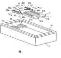
图1为用于说明根据本发明的第一实施方式构成的音叉式晶体谐振器的基座和音叉晶体谐振板的分解斜视图。1 is an exploded perspective view illustrating a base and a tuning-fork crystal resonator plate of a tuning-fork crystal resonator according to a first embodiment of the present invention.
图2给出了根据本发明的实施方式的音叉式晶体谐振器的沿图1中的箭头所指方向的A-A线的截面图。FIG. 2 shows a cross-sectional view of the tuning-fork crystal resonator according to an embodiment of the present invention along the line A-A in the direction indicated by the arrow in FIG. 1 .
图3为根据本发明的第二实施方式的音叉式晶体谐振器的截面图。3 is a cross-sectional view of a tuning-fork crystal resonator according to a second embodiment of the present invention.
图4(a)至4(d)为根据其他变化例的音叉式晶体谐振器的斜视图。4(a) to 4(d) are perspective views of tuning-fork crystal resonators according to other variations.
图5(a)至5(c)为根据其他变化例的音叉式晶体谐振器的斜视图。5(a) to 5(c) are perspective views of tuning-fork crystal resonators according to other variations.
具体实施方式Detailed ways
此后,将参考附图对本发明的第一实施方式进行说明。需注意在下述实施方式中,本发明用于作为压电谐振器的音叉式晶体谐振器。Hereinafter, a first embodiment of the present invention will be described with reference to the drawings. Note that in the following embodiments, the present invention is applied to a tuning-fork crystal resonator as a piezoelectric resonator.
如图1和2所示,根据本发明的音叉式晶体谐振器1包括音叉晶体谐振板2(此处所称的压电谐振板),用于支撑音叉晶体谐振板2的基座3,以及用于气密地密封支撑在基座3上的音叉式晶体谐振板2的顶盖4。在音叉式晶体谐振器1中,如图2所示,基座3和顶盖4接合在一起形成外壳,音叉式晶体谐振板2固定至外壳内部11的基座3上,外壳内部11被气密密封。在此情况下,如图2所示,基座3和音叉式晶体谐振板2通过导电接合部件5接合在一起。As shown in Figures 1 and 2, a tuning
接下来,说明该音叉式晶体谐振器1的每个元件。基座3由诸如陶瓷材料制成,如图1所示,形成为盒状,包括底面部分31和从底面部分31向上延伸的侧壁部分32。侧壁部分32沿底面部分31表面的外围设置。在基座3的侧壁部分32的上端部分33上提供用于接合顶盖4的金属化层34。另外,电连接至后述的音叉式晶体谐振板2的引线电极65a和65b的电极焊盘35和36被设置于位于基座3的内部(见外壳内部11)的底面部分31的一侧的两个端部,基座3由底面部分31和侧壁部分32所限定。这些电极焊盘35和36电连接至形成于基座3的背面的各个端子电极(未示出),并通过这些端子电极连接至外部装置。电极焊盘35和36以及端子电极通过在印刷金属化材料如钨、钼等后将这些部件和基座3焙烧来形成,例如在其上设置镍镀层和金镀层。Next, each element of this tuning-fork
如图2所示,顶盖4由金属化材料构成,以从顶部看呈矩形的矩形实体(单板)的形状形成。在顶盖4的下表面形成未示出的蜡状材料,并通过缝焊熔接(seam welding)或者束焊熔接(beam welding)法接合至基座3,这样就形成了由顶盖4和基座3构成的音叉式晶体谐振器1的外壳。用于本发明的外壳内部11指的是由顶盖4和基座3气密地密封的部分。顶盖4也可以由陶瓷材料构成,并可以通过玻璃材料获得气密密封。As shown in FIG. 2 , the
作为用于导电接合部件5的材料,例如采用包括多个银填充物的硅树脂导电粘合剂。通过固化导电粘合剂,多个银填充物结合为导电物质。尽管采用了包含多个银填充物的硅树脂,但本发明并不限于此。As a material for the
音叉式晶体谐振板2,如图1和2所示,通过刻蚀由各向异性的晶体构成的基板6形成。基板6包括由两个分叉部分61a和61b(第一分叉部和第二分叉部)构成的振荡部、以及基部62,分叉部61a和61b从基部62延伸,基部62以宽于振荡部(分叉部61和分叉部62)的方式形成。在两个分叉部61a和61b的两个主面(前主面和后主面)上形成凹槽63a和63b。用于本例的凹槽63a和63b具有如图1所示的凹形截面。但是,本发明不仅限于此,凹槽63a和63b可以为通孔或者凹坑。The tuning-fork
在音叉式晶体谐振板2的表面上设置图中未示出的具有不同电势的两个激励电极(第一激励电极和第二激励电极),以及从激励电极引出以将激励电极电连接至电极焊盘35和36(此处所称的外部电极)的引线电极65a和65b(此处所称的导电接合部件形成区域)。在图1和图2中,部分地示出了引线电极65a和65b,用于本实施方式中的引线电极指的是从两个激励电极引线的电极。Two excitation electrodes (first excitation electrode and second excitation electrode) with different potentials not shown in the figure are set on the surface of the tuning fork type
另外,两个激励电极(第一激励电极和第二激励电极)的一部分形成于凹槽63a和63b内。这样,即便当音叉式晶体谐振板2的制造尺寸较小时,在分叉部分61a和61b的振荡损失也会得到抑制,CI值(晶体阻抗)可保持较低。两个激励电极中,第一激励电极由形成于第一分叉部61a的两个主面(前主面和后主面)上和凹槽63a中的第一主面电极(未示出)、以及形成于第二分叉部61b的两个侧面上的第二侧面电极(未示出)构成。第一主面电极和第二侧面电极通过连线电极(未示出)相互连接并引出至引线电极65a(或者引线电极65b)。类似的,第二激励电极由形成于第二分叉部61b的两个主面(前主面和后主面)上和凹槽63b中的第二主面电极(未示出)和形成于第一分叉部61a的两个侧面上的第一侧面电极(未示出)构成。第二主面电极和第一侧面电极通过连线电极(未示出)相互连接并引出至引线电极65b(或者引线电极65a)。In addition, parts of two excitation electrodes (first excitation electrode and second excitation electrode) are formed in the
上述激励电极各自为由例如铬制的下层电极层和金制的上层电极层构成的多层薄膜。该薄膜通过诸如在利用真空蒸镀法形成于整个表面上之后利用光刻技术进行金属刻蚀以形成期望的形状。同样,图1和图2中所示的上述引线电极65a和65b各自为由铬制的底层电极层和金制的中间电极层以及铬制的上层电极层构成的多层薄膜。该薄膜通过诸如在利用真空蒸镀法形成于整个表面上之后利用光刻技术进行金属刻蚀以形成期望的形状,只有铬制的上层电极层是利用诸如部分掩模的真空蒸镀法形成的。尽管激励电极按铬和金的顺序形成,激励电极还可以按诸如铬和银、或者铬、金、铬、或者铬、银、铬的顺序形成。此外,尽管引线电极65a和65b按铬、金、铬的顺序形成,引线电极65a和65b还可按例如铬、银、铬的顺序形成。The aforementioned excitation electrodes are each a multilayer thin film composed of, for example, a lower electrode layer made of chromium and an upper electrode layer made of gold. The thin film is formed into a desired shape by, for example, metal etching using a photolithography technique after being formed on the entire surface by a vacuum evaporation method. Also, the above-mentioned
关于音叉式晶体谐振板2的基部62,如图1所示,该基部62以宽于振荡部(分叉部61a和61b)的方式形成,并具有与振荡部具有相同宽度且振荡部(分叉部61a和61b)由此延伸的基部中央区域621、以及沿振荡部的宽度方向延伸出的基部拓宽区域622和623。即,如图1所示,基部62由基部拓宽区域622和623相邻着基部中央区域621地构成。如图1所示,设计成较窄宽度并具有凹形截面的延长的薄壁部分7a和7b在基部62的两个主面(前主面和后主面)上形成。该薄壁部分7a和7b的形成从位于基部中央区域621和基部拓宽区域622和623之间的边界69上的边界角部64a和64b(作为一个端部)开始,该边角部位于基部62的、分叉部61a和62a由此延伸的一侧。即,边角部64a和64b用作开始端部,是薄壁部7a和7b的一个端部。此外,薄壁部7a和7b从基部拓宽区域622和623穿过基部中央区域621上方,当图1中所示的基部62从上面看时,薄壁部7a和7b的终端部71a和71b(另一端部)位于基部62中比导电接合部件形成区域(图1所示的引线电极65a和65b)更内侧处。这样,当图1所示的基部62从上方看时,图1中所示的引线电极65a和65b形成于基部62内的薄壁部的外侧上。这样,如图1所示,薄壁部7a和7b被形成以阻止导电接合部件形成区域(图1所示的引线电极65a和65b)与振荡部(分叉部61a和61b)之间的线性连接。即,薄壁部7a和7b位于振荡部(分叉部61a和61b)和导电接合部件形成区域(图1所示引线电极65a和65b)之间。另外,薄壁部7a和7b通过利用光刻技术进行半刻蚀形成期望的形状,在本实施方式中,以相对置的方式形成于基部62的上下表面(两主面)上。Regarding the
音叉式晶体谐振板2的引线电极65a和65b与基座3的引线电极65a和65b通过导电接合部件5接合在一起,这样,引线电极65a和65b与电极板35和36相互电连接。The
如上所述,根据本实施方式的音叉式晶体谐振板2,可以不增加音叉式晶体谐振板2的基部62的长度地将形成了用于与底座3地电极焊盘35、36接合的如图1所述的引线电极65a、65b的二个导电接合部件形成区域相互隔离,同时在基部拓宽区域622和623内有效布置导电接合部件形成区域(图1所示的引线电极65a和65b),并且音叉式晶体谐振板2与基座3的接合强度不会降低。此外,音叉式晶体谐振板2的刚性不会降低,分叉部61a和61b内的振荡向导电接合部件形成区域(图1所示引线电极65a和65b)的泄漏可以得到更加有效的缓解。As described above, according to the tuning fork type
就是说,根据本实施方式的音叉式晶体谐振板2,由振荡部(分叉部61a和61b)发生的振荡能量的传输被基部拓宽区域622和623减弱,并且被从位于基部中央区域621和基部拓宽区域622、623之间的边界角部64a和64b开始的薄壁部分7a和7b有效阻挡。因此,可以减少振荡从振荡部(分叉部61a和61b)向每个导电接合部件形成区域(图1所示引线电极65a和65b)的泄漏,而实现基部62尺寸的缩减。另外,由于开始于位于基部中央区域621和基部拓宽区域622、623之间的边角部64a、64b的延长的薄壁部分7a和7b得以形成,可以在不增加压电谐振板2的基部62长度的同时,在基部拓宽区域622、623内有效布置导电接合部件形成区域(图1所示引线电极65a和65b),同时压电谐振板2的接合强度不被降低。此外,由于薄壁部分7a和7b得到延长,压电谐振板2的基部62的刚性不被降低,不会出现压电谐振板2破损或者类似情形。That is to say, according to the tuning fork type
接下来,将参考图3对本发明的第二实施方式进行说明。与第一实施方式相同,根据第二实施方式本发明用于作为压电谐振器件的音叉式晶体谐振器。这样,在第二实施方式中,将对与上述第一实施方式的结构的不同之处进行说明,而相同的结构将被省略。因此,相同结构的功能和效果与上述第一实施方式相同。Next, a second embodiment of the present invention will be described with reference to FIG. 3 . Like the first embodiment, according to the second embodiment the present invention is applied to a tuning-fork crystal resonator as a piezoelectric resonant device. Thus, in the second embodiment, the differences from the structure of the first embodiment described above will be described, and the same structures will be omitted. Therefore, the functions and effects of the same structure are the same as those of the first embodiment described above.
第二实施方式与上述第一实施方式不同之处在于,将诸如金属凸起或者镀金属凸起之类的导电凸起用作导电接合部件5的材料。即,例如,将诸如金凸起的金属凸起51置于音叉式晶体谐振板2的引线电极65a、65b与基座3的电极焊盘35、36之间,引线电极65a、65b和电极焊盘35、36通过从上方对音叉式晶体谐振板2施加超声波彼此相接合。此时,与第一实施方式的导电粘合剂的情形相比,导电接合部件形成区域(图3所示引线电极65a和65b)的面积会减小,这将使得音叉式晶体谐振板2的尺寸进一步减小。另外,在本实施方式中,可以利用薄壁部分7a、7b吸收接合金凸起时因施加超声波而带来的冲击,从而可以避免压电谐振板2的损坏或者破碎。The second embodiment differs from the first embodiment described above in that a conductive bump such as a metal bump or a metal-plated bump is used as the material of the
然后,参考图4(图4(a)至图4(d))和图5(图5(a)至图5(c)),关于本发明的上述实施方式,对薄壁部分7a和7b的变化例以及音叉式晶体谐振板2的导电接合部件形成区域(图1中所示的引线电极65a和65b在基部62中形成的位置)的构造的变化例进行说明。在不同示例中,将对区别于所示实施方式的结构进行说明,相同结构的说明将被省略。因此,相同结构的功能和效果与上述第一和第二实施方式的相同。Then, with reference to Fig. 4 (Fig. 4(a) to Fig. 4(d)) and Fig. 5 (Fig. A modification example of the structure of the tuning-fork type
图4(a)中的音叉式晶体谐振板2与上述实施方式的不同之处在于,薄壁部分7a和7b是利用光刻技术仅在前面(对前主面)进行半刻蚀而形成的。要注意的是,半刻蚀的表面可以位于接合部的一侧或者另一侧。The difference between the tuning fork type
在图4(b)的音叉式晶体谐振板2中,薄壁部分7a和7b的形成始于位于基部中央区域621和基部拓宽区域622和623之间的边界69上的边界角部64a和64b(作为一个端部),64a和64b位于基部62的、分叉部61a和61b延伸出的一侧。这些薄壁部分7a和7b沿边界69形成,当从上方看图4(b)所示的基部62时,薄壁部分7a和7b的端部71a和71b(另一端部)位于基部62中比构成导电接合部件形成区域的引线电极65a和65b更内侧的位置。另外,当从上方看图4(b)所示的基部62时,导电接合部件形成区域(图4(b)中所示的引线电极65a和65b)相邻于(平行于)基部62中的薄壁部分7a和7b的外侧地放置。这样,即便当形成于导电接合部件形成区域中的引线电极65a和65b靠近振荡部(分叉部61a和61b)放置,振荡泄漏的影响也变小,从而可以通过抑制基部长度的增加实现基部尺寸的进一步减小。In the tuning-fork type
图4(c)中的音叉式晶体谐振板2与上述实施方式的不同在于,薄壁部分7a和7b为利用光刻技术仅对前面的主面(前主面)进行半刻蚀而形成,与图4(a)中所示的薄壁部分7a和7b的情形相同。要注意的是,半刻蚀的表面可以位于接合部的一侧或者另一侧。此外,在图4(c)中的音叉式晶体谐振板2中,薄壁部分7a和7b的形成始于位于基部中央区域621和基部拓宽区域622和623之间的边界69上的边界角部66a和66b(作为一个端部),66a和66b位于基部62的分叉部61a和61b延伸出的一侧的相反一侧。这些薄壁部分7a和7b沿边界69形成,当从上方看图4(c)所示的基部62时,薄壁部分7a和7b的终端部71a和71b(另一端部)位于基部62内的比构成导电接合部件形成区域的引线电极65a和65b更内侧的位置。此外,当从上方看图4(c)所示的基部62时,导电接合部件形成区域(图4(c)中所示的引线电极65a和65b)相邻于(平行于)薄壁部分7a和7b的基部62的外侧放置。The difference between the tuning-fork type
在图4(d)的音叉式晶体谐振板2中,薄壁部分7a、7b和8a、8b的形成始于位于基部62(在基部拓宽区域622和623内)内之边界区域(边界69)外侧的角部67a、67b、68a、68b(作为端部之一),而不是如上所述始于上述的位于基部中央区域621和基部拓宽区域622和623之间的边界角部64a、64b、66a、66b。尤其是,在图4(d)的音叉式晶体谐振板2中,薄壁部分7a、7b的形成始于位于基部拓宽区域622、623内、基部62的分叉部61a、61b延伸出的一侧上的角部67a和67b(作为端部之一)。这些薄壁部分7a和7b沿边界69形成,当从上方看图4(d)所示的基部62时,薄壁部分7a和7b的端部71a和71b(另一端部)位于基部62内的比构成导电接合部件形成区域的引线电极65a和65b更内侧的位置。同样,薄壁部分8a、8b的形成始于位于基部拓宽区域622、623内、并在基部62的、分叉部61a、61b延伸出的一侧的相反侧上的角部68a和68b(作为端部之一)。这些薄壁部分8a和8b沿边界69形成。这样,导电接合部件形成区域(图4(d)所示的引线电极65a和65b)可以与振荡部(分叉部61a和61b)相邻地放置,从而以通过抑制基部长度的增加实现基部尺寸的进一步减小。此外,薄壁部分7a、7b、8a、8b在基部62中的角部67a、67b、68a、68b相对置地放置。这样在不增加音叉式晶体谐振板2的基部62的长度的前提下,可以更有效地缓解分叉部61a、61b内的振荡向基部62的泄漏。特别是,产生于振荡部(分叉部61a和61b)的振荡能量的传输被基部拓宽区域622、623减弱,并由开始于分叉部由此延伸出的基部拓宽区域622、623一侧上的角部的薄壁部分7a和7b在最靠近振荡部(分叉部61a和61b)的位置有效阻挡。由此,可以在实现基部62尺寸减小的同时,抑制振荡泄漏向基部62的扩散,减少从振荡部(分叉部61a和61b)向每个导电接合部件形成区域(图4(d)所示的引线电极65a和65b)的振荡泄漏。In the tuning-fork type
图5(a)中的音叉式晶体谐振板2与上述实施方式的不同在于,薄壁部分7a和7b为利用光刻技术仅对前面的主面(前主面)进行半刻蚀而成,与图4(a)中所示的薄壁部分7a和7b的情形相同。要注意的是,半刻蚀的表面可以位于接合部的一侧或者另一侧。此外,图5(a)中所示的薄壁部分7a和7b的形成始于位于基部中央区域621和基部拓宽区域622和623之间的边界69上的边界角部64a和64b(作为一个端部),该边界角部64a和64b位于基部62的、分叉部61a和61b延伸出的一侧。另外,当从上方看图5(a)所示的基部62时,薄壁部7a和7b从基部拓宽区域622和623穿过基部中央区域621上方,并向基部62的、分叉部61a和61b延伸出一侧的相反侧弯曲。即,当从上方看图5(a)所示的基部62时,薄壁部分7a和7b弯曲使得薄壁部分7a和7b在图中向下凸出。薄壁部分7a和7b的终端部71a和71b(另一端部)位于基部62内的比导电接合部件形成区域(图5(a)中的引线电极65a和65b)更内侧的位置。即,图5(a)中的引线电极65a和65b形成于图5(a)所示的基部62内的薄壁部分7a和7b的外侧。另外,薄壁部分7a和7b的形状不仅限于如图5(a)所示的薄壁部分7a和7b弯曲的形状,薄壁部分7a和7b还可以从一端部(边界角部64a和64b)向终端部71a和71b(另一端部)分段地形成,引线电极65a和65b还可以在基部62中的薄壁部分7a和7b的外侧上形成。The difference between the tuning fork type
图5(b)中的音叉式晶体谐振板2与上述实施方式的不同在于,薄壁部分7a和7b为利用光刻技术仅对前主面进行半刻蚀而成,这与图4(a)中所示的薄壁部分7a和7b的情形相同。要注意的是,半刻蚀的表面可以位于接合部的一侧或者另一侧。但是,半刻蚀的表面优选为基部62的前主面,以便得到对未示出的激励电极的良好的导电状态,从而使激励电极电连接至电极焊盘35和36。在图5(b)中所示的音叉式晶体谐振板2中,薄壁部分7a和7b沿位于基部中央区域621和基部拓宽区域622和623之间的边界69并大致在其上形成,并从基部62的、分叉部61a、61b延伸出的一侧伸向另一侧。因此,当从上方看图5(b)所示的基部62时,薄壁部7a和7b被置于基部62中比构成导电接合部件形成区域的引线电极65a和65b更内侧的位置。The difference between the tuning fork type
图5(c)中的音叉式晶体谐振板2与上述实施方式的不同在于,薄壁部分7a和7b为利用光刻技术仅对前面的主面(前主面)进行半刻蚀而成,这与图4(a)中所示的薄壁部分7a和7b的情形相同。要注意的是,半刻蚀的表面可以位于接合部的一侧或者另一侧。但是,半刻蚀的表面优选为基部62的前主面,以便得到对未示出的激励电极的良好的导电状态,从而使激励电极电连接至电极焊盘35和36。另外,在图5(c)中所示的音叉式晶体谐振板2中,薄壁部分7a和7b的形成始于位于基部中央区域621和基部拓宽区域622和623之间的边界69上的边界角部66a和66b(作为端部之一),边界角部66a和66b位于基部62的、分叉部61a和61b延伸出的一侧的反面。薄壁部分7a和7b沿边界69形成,并在基部62的宽度方向弯曲到达基部拓宽区域622、623的侧表面,用作薄壁部分7a和7b的终端部71a和71b(另一端部),以包围图5(c)中所示的引线电极65a和65b。The difference between the tuning fork type
在不偏离本发明主旨及其基本特征的前提下,本发明可以其他不同的形式得到实施。例如,尽管在上述实施方式中公开了薄壁部分的终端部位于基部中比导电接合部件形成区域更内侧的位置的方式,但该方式仅为优选例,本发明不仅限于此。此外,尽管公开了薄壁部分抑制导电接合部件形成区域和振荡部的线性连接的方式,但该方式仅为优选例,本发明不仅限于此。此外,尽管薄壁部分在基部的中间部分具有终端部,薄壁部分还可以一直穿过基部。因此,上述实施方式从所有方面考虑仅是说明性的而并不具有限制性。本发明的范围由后附权利要求而不是前述说明给出。所有落入所附权利要求的等效范围的改动和修正均包含于其中。On the premise of not departing from the gist and essential features of the present invention, the present invention can be implemented in other different forms. For example, although the above embodiment discloses that the end portion of the thin portion is located inside the base portion from the conductive bonding member forming region, this is only a preferable example and the present invention is not limited thereto. In addition, although the method in which the thin-walled portion suppresses the linear connection between the conductive bonding member forming region and the oscillation part is disclosed, this method is only a preferable example, and the present invention is not limited thereto. Furthermore, although the thin-walled portion has a terminal portion at the middle portion of the base, the thin-walled portion may go all the way through the base. Therefore, the above-mentioned embodiments are only illustrative and not restrictive in all points of view. The scope of the invention is given by the appended claims rather than the foregoing description. All changes and modifications that come within the equivalent scope of the appended claims are intended to be embraced therein.
本申请对2005年6月30日提出的日本专利申请第2005-190822号享有优先权,其所有内容通过参考包含于此。This application claims priority from Japanese Patent Application No. 2005-190822 filed on June 30, 2005, the entire contents of which are hereby incorporated by reference.
工业应用性Industrial applicability
作为根据本发明的压电谐振板的材料,尤其适用于晶体振荡器。As a material of the piezoelectric resonance plate according to the present invention, it is suitable especially for a crystal oscillator.
Claims (7)
Applications Claiming Priority (2)
| Application Number | Priority Date | Filing Date | Title |
|---|---|---|---|
| JP190822/2005 | 2005-06-30 | ||
| JP2005190822 | 2005-06-30 |
Publications (1)
| Publication Number | Publication Date |
|---|---|
| CN101199114Atrue CN101199114A (en) | 2008-06-11 |
Family
ID=37604224
Family Applications (1)
| Application Number | Title | Priority Date | Filing Date |
|---|---|---|---|
| CNA2006800219065APendingCN101199114A (en) | 2005-06-30 | 2006-04-21 | Piezoelectric resonator plate and piezoelectric resonator |
Country Status (4)
| Country | Link |
|---|---|
| US (1) | US20090051252A1 (en) |
| JP (1) | JPWO2007004348A1 (en) |
| CN (1) | CN101199114A (en) |
| WO (1) | WO2007004348A1 (en) |
Cited By (4)
| Publication number | Priority date | Publication date | Assignee | Title |
|---|---|---|---|---|
| CN103152007A (en)* | 2009-12-02 | 2013-06-12 | 威华微机电股份有限公司 | Tuning Fork Quartz Crystal Resonator |
| CN101340179B (en)* | 2007-07-02 | 2013-06-12 | 日本电波工业株式会社 | Piezoelectric vibrating pieces and piezoelectric devices |
| CN107681991A (en)* | 2011-03-18 | 2018-02-09 | 精工爱普生株式会社 | Piezoelectric vibration device, piezoelectric vibrator, piezoelectric oscillator and electronic equipment |
| CN111256673A (en)* | 2020-01-19 | 2020-06-09 | 北京晨晶电子有限公司 | Connecting structure and connecting method of quartz tuning fork and base and application of connecting structure and connecting method |
Families Citing this family (19)
| Publication number | Priority date | Publication date | Assignee | Title |
|---|---|---|---|---|
| CA3010578C (en) | 2009-04-01 | 2021-03-09 | Tearscience, Inc. | Ocular surface interferometry (osi) devices, systems, and methods for imaging, processing, and/or displaying an ocular tear film and/or measuring ocular tear film layer thickness(es) |
| US9642520B2 (en) | 2009-04-01 | 2017-05-09 | Tearscience, Inc. | Background reduction apparatuses and methods of ocular surface interferometry (OSI) employing polarization for imaging, processing, and/or displaying an ocular tear film |
| US8888286B2 (en) | 2009-04-01 | 2014-11-18 | Tearscience, Inc. | Full-eye illumination ocular surface imaging of an ocular tear film for determining tear film thickness and/or providing ocular topography |
| US9888839B2 (en) | 2009-04-01 | 2018-02-13 | Tearscience, Inc. | Methods and apparatuses for determining contact lens intolerance in contact lens wearer patients based on dry eye tear film characteristic analysis and dry eye symptoms |
| JP5432582B2 (en)* | 2009-04-28 | 2014-03-05 | 京セラクリスタルデバイス株式会社 | Crystal oscillator |
| TWI398097B (en)* | 2009-11-18 | 2013-06-01 | Wafer Mems Co Ltd | Tuning fork quartz crystal resonator |
| JP2011151562A (en)* | 2010-01-21 | 2011-08-04 | Kyocera Kinseki Corp | Tuning fork type bent crystal vibration element |
| JP5085679B2 (en) | 2010-03-15 | 2012-11-28 | 日本電波工業株式会社 | Piezoelectric vibrating piece and piezoelectric device |
| JP5942590B2 (en)* | 2012-05-23 | 2016-06-29 | セイコーエプソン株式会社 | Force detection element, force detection module, force detection unit and robot |
| JP6005442B2 (en)* | 2012-08-23 | 2016-10-12 | 京セラクリスタルデバイス株式会社 | Crystal oscillator |
| US9339177B2 (en) | 2012-12-21 | 2016-05-17 | Tearscience, Inc. | Full-eye illumination ocular surface imaging of an ocular tear film for determining tear film thickness and/or providing ocular topography |
| JP2014175802A (en)* | 2013-03-07 | 2014-09-22 | Sii Crystal Technology Inc | Electronic component |
| JP6363328B2 (en)* | 2013-03-27 | 2018-07-25 | 京セラ株式会社 | Crystal device |
| JP6171475B2 (en)* | 2013-03-28 | 2017-08-02 | セイコーエプソン株式会社 | Manufacturing method of vibrating piece |
| US10278587B2 (en) | 2013-05-03 | 2019-05-07 | Tearscience, Inc. | Eyelid illumination systems and method for imaging meibomian glands for meibomian gland analysis |
| US9795290B2 (en) | 2013-11-15 | 2017-10-24 | Tearscience, Inc. | Ocular tear film peak detection and stabilization detection systems and methods for determining tear film layer characteristics |
| JP6598618B2 (en)* | 2015-09-24 | 2019-10-30 | 京セラ株式会社 | Tuning fork type piezoelectric element, tuning fork type vibration element and tuning fork type vibration device |
| JP6659288B2 (en)* | 2015-09-28 | 2020-03-04 | 京セラ株式会社 | A tuning fork crystal element and a crystal device on which the tuning fork crystal element is mounted. |
| JP6698338B2 (en)* | 2015-12-25 | 2020-05-27 | 京セラ株式会社 | Tuning fork type crystal element and crystal device on which the tuning fork type crystal element is mounted |
Family Cites Families (9)
| Publication number | Priority date | Publication date | Assignee | Title |
|---|---|---|---|---|
| JP4641111B2 (en)* | 2001-03-23 | 2011-03-02 | シチズンホールディングス株式会社 | Method for manufacturing piezoelectric device element |
| JP4329286B2 (en)* | 2001-08-27 | 2009-09-09 | セイコーエプソン株式会社 | Vibrating piece, vibrator, oscillator and electronic device |
| JP3812724B2 (en)* | 2001-09-13 | 2006-08-23 | セイコーエプソン株式会社 | Vibrating piece, vibrator, oscillator and electronic device |
| JP2004260718A (en)* | 2003-02-27 | 2004-09-16 | Seiko Epson Corp | Tuning fork vibrating reed, method of manufacturing tuning fork vibrating reed, and piezoelectric device |
| JP2004289478A (en)* | 2003-03-20 | 2004-10-14 | Seiko Epson Corp | Bonding structure of piezoelectric vibrating reed, piezoelectric device and manufacturing method thereof, mobile phone device using piezoelectric device, and electronic device using piezoelectric device |
| JP4049017B2 (en)* | 2003-05-16 | 2008-02-20 | セイコーエプソン株式会社 | Piezoelectric vibrator |
| JP3951058B2 (en)* | 2003-08-19 | 2007-08-01 | セイコーエプソン株式会社 | Tuning fork type piezoelectric vibrating piece |
| JP4329492B2 (en)* | 2003-10-28 | 2009-09-09 | セイコーエプソン株式会社 | Piezoelectric vibrating piece, piezoelectric device, manufacturing method thereof, mobile phone device using the piezoelectric device, and electronic equipment using the piezoelectric device |
| JP2004112843A (en)* | 2003-12-19 | 2004-04-08 | Seiko Epson Corp | Piezoelectric device, method for manufacturing piezoelectric vibrating piece, mobile phone device using piezoelectric device, and electronic device using piezoelectric device |
- 2006
- 2006-04-21USUS11/921,639patent/US20090051252A1/ennot_activeAbandoned
- 2006-04-21CNCNA2006800219065Apatent/CN101199114A/enactivePending
- 2006-04-21WOPCT/JP2006/308444patent/WO2007004348A1/enactiveApplication Filing
- 2006-04-21JPJP2007523353Apatent/JPWO2007004348A1/enactivePending
Cited By (7)
| Publication number | Priority date | Publication date | Assignee | Title |
|---|---|---|---|---|
| CN101340179B (en)* | 2007-07-02 | 2013-06-12 | 日本电波工业株式会社 | Piezoelectric vibrating pieces and piezoelectric devices |
| CN103152007A (en)* | 2009-12-02 | 2013-06-12 | 威华微机电股份有限公司 | Tuning Fork Quartz Crystal Resonator |
| CN103152007B (en)* | 2009-12-02 | 2016-12-28 | 威华微机电股份有限公司 | Tuning Fork Quartz Crystal Resonator |
| CN107681991A (en)* | 2011-03-18 | 2018-02-09 | 精工爱普生株式会社 | Piezoelectric vibration device, piezoelectric vibrator, piezoelectric oscillator and electronic equipment |
| CN107681991B (en)* | 2011-03-18 | 2020-12-01 | 精工爱普生株式会社 | Piezoelectric vibration element, piezoelectric vibrator, piezoelectric oscillator, and electronic equipment |
| CN111256673A (en)* | 2020-01-19 | 2020-06-09 | 北京晨晶电子有限公司 | Connecting structure and connecting method of quartz tuning fork and base and application of connecting structure and connecting method |
| CN111256673B (en)* | 2020-01-19 | 2021-09-10 | 北京晨晶电子有限公司 | Connecting structure and connecting method of quartz tuning fork and base and application of connecting structure and connecting method |
Also Published As
| Publication number | Publication date |
|---|---|
| JPWO2007004348A1 (en) | 2009-01-22 |
| WO2007004348A1 (en) | 2007-01-11 |
| US20090051252A1 (en) | 2009-02-26 |
Similar Documents
| Publication | Publication Date | Title |
|---|---|---|
| CN101199114A (en) | Piezoelectric resonator plate and piezoelectric resonator | |
| EP1478090B1 (en) | Tuning-fork-type piezoelectric resonator element | |
| JP4552916B2 (en) | Piezoelectric vibration device | |
| JP3965070B2 (en) | Surface mount crystal unit | |
| CN103430450A (en) | Piezoelectric vibrating reed, piezoelectric vibrator, method for manufacturing piezoelectric vibrating reed, and method for manufacturing piezoelectric vibrator | |
| JP5146222B2 (en) | Piezoelectric vibration device | |
| CN114208027A (en) | Piezoelectric vibrating plate, piezoelectric vibrating device, and method for manufacturing piezoelectric vibrating device | |
| JP5181938B2 (en) | Tuning fork crystal unit | |
| CN101237223B (en) | Tuning fork piezoelectric vibrator | |
| JP2011193436A (en) | Tuning fork crystal resonator chip, tuning fork crystal resonator, and method of manufacturing the tuning fork crystal resonator chip | |
| WO2011034104A1 (en) | Piezoelectric vibration piece and manufacturing method of piezoelectric vibration piece | |
| JP2009055354A (en) | Package for piezoelectric vibration device and piezoelectric vibration device | |
| JP2018006901A (en) | Crystal diaphragm, and crystal vibration device | |
| JP5554473B2 (en) | Electronic component package and piezoelectric vibration device | |
| JP2002026679A (en) | Package for piezoelectric vibration device | |
| JP2009081670A (en) | Piezoelectric vibration device and manufacturing method thereof | |
| JP2010136243A (en) | Vibrator | |
| JP4720933B2 (en) | Piezoelectric vibrating piece | |
| JP2009111124A (en) | Electronic device and electronic device package | |
| JP7380067B2 (en) | A tuning fork type piezoelectric vibrating piece and a tuning fork type piezoelectric vibrator using the tuning fork type piezoelectric vibrating piece | |
| JP4373309B2 (en) | Package for electronic components | |
| JP4784685B2 (en) | Piezoelectric vibrating piece | |
| JP6760430B1 (en) | Crystal vibration device | |
| JP5071164B2 (en) | Electronic device and method for manufacturing electronic device | |
| JP2018037896A (en) | Tuning fork type piezoelectric vibrating piece and tuning fork type piezoelectric vibrator using the tuning fork type piezoelectric vibrating piece |
Legal Events
| Date | Code | Title | Description |
|---|---|---|---|
| C06 | Publication | ||
| PB01 | Publication | ||
| C02 | Deemed withdrawal of patent application after publication (patent law 2001) | ||
| WD01 | Invention patent application deemed withdrawn after publication |