CN101198964A - Creating three-dimensional images of objects using infrared pattern illumination - Google Patents
Creating three-dimensional images of objects using infrared pattern illuminationDownload PDFInfo
- Publication number
- CN101198964A CN101198964ACNA200680007575XACN200680007575ACN101198964ACN 101198964 ACN101198964 ACN 101198964ACN A200680007575X ACNA200680007575X ACN A200680007575XACN 200680007575 ACN200680007575 ACN 200680007575ACN 101198964 ACN101198964 ACN 101198964A
- Authority
- CN
- China
- Prior art keywords
- image
- dimensional
- pixels
- pixel
- pattern
- Prior art date
- Legal status (The legal status is an assumption and is not a legal conclusion. Google has not performed a legal analysis and makes no representation as to the accuracy of the status listed.)
- Pending
Links
Images


Classifications
- G—PHYSICS
- G01—MEASURING; TESTING
- G01B—MEASURING LENGTH, THICKNESS OR SIMILAR LINEAR DIMENSIONS; MEASURING ANGLES; MEASURING AREAS; MEASURING IRREGULARITIES OF SURFACES OR CONTOURS
- G01B11/00—Measuring arrangements characterised by the use of optical techniques
- G01B11/24—Measuring arrangements characterised by the use of optical techniques for measuring contours or curvatures
- G01B11/25—Measuring arrangements characterised by the use of optical techniques for measuring contours or curvatures by projecting a pattern, e.g. one or more lines, moiré fringes on the object
- G01B11/2513—Measuring arrangements characterised by the use of optical techniques for measuring contours or curvatures by projecting a pattern, e.g. one or more lines, moiré fringes on the object with several lines being projected in more than one direction, e.g. grids, patterns
- G—PHYSICS
- G01—MEASURING; TESTING
- G01B—MEASURING LENGTH, THICKNESS OR SIMILAR LINEAR DIMENSIONS; MEASURING ANGLES; MEASURING AREAS; MEASURING IRREGULARITIES OF SURFACES OR CONTOURS
- G01B11/00—Measuring arrangements characterised by the use of optical techniques
- G01B11/24—Measuring arrangements characterised by the use of optical techniques for measuring contours or curvatures
- G01B11/25—Measuring arrangements characterised by the use of optical techniques for measuring contours or curvatures by projecting a pattern, e.g. one or more lines, moiré fringes on the object
- G01B11/2545—Measuring arrangements characterised by the use of optical techniques for measuring contours or curvatures by projecting a pattern, e.g. one or more lines, moiré fringes on the object with one projection direction and several detection directions, e.g. stereo
- G—PHYSICS
- G06—COMPUTING OR CALCULATING; COUNTING
- G06T—IMAGE DATA PROCESSING OR GENERATION, IN GENERAL
- G06T7/00—Image analysis
- G06T7/50—Depth or shape recovery
- G06T7/521—Depth or shape recovery from laser ranging, e.g. using interferometry; from the projection of structured light
- G—PHYSICS
- G06—COMPUTING OR CALCULATING; COUNTING
- G06T—IMAGE DATA PROCESSING OR GENERATION, IN GENERAL
- G06T7/00—Image analysis
- G06T7/50—Depth or shape recovery
- G06T7/55—Depth or shape recovery from multiple images
- G—PHYSICS
- G06—COMPUTING OR CALCULATING; COUNTING
- G06V—IMAGE OR VIDEO RECOGNITION OR UNDERSTANDING
- G06V10/00—Arrangements for image or video recognition or understanding
- G06V10/10—Image acquisition
- G06V10/12—Details of acquisition arrangements; Constructional details thereof
- G06V10/14—Optical characteristics of the device performing the acquisition or on the illumination arrangements
- G06V10/143—Sensing or illuminating at different wavelengths
- G—PHYSICS
- G06—COMPUTING OR CALCULATING; COUNTING
- G06V—IMAGE OR VIDEO RECOGNITION OR UNDERSTANDING
- G06V10/00—Arrangements for image or video recognition or understanding
- G06V10/10—Image acquisition
- G06V10/12—Details of acquisition arrangements; Constructional details thereof
- G06V10/14—Optical characteristics of the device performing the acquisition or on the illumination arrangements
- G06V10/145—Illumination specially adapted for pattern recognition, e.g. using gratings
- G—PHYSICS
- G06—COMPUTING OR CALCULATING; COUNTING
- G06T—IMAGE DATA PROCESSING OR GENERATION, IN GENERAL
- G06T2200/00—Indexing scheme for image data processing or generation, in general
- G06T2200/08—Indexing scheme for image data processing or generation, in general involving all processing steps from image acquisition to 3D model generation
- G—PHYSICS
- G06—COMPUTING OR CALCULATING; COUNTING
- G06V—IMAGE OR VIDEO RECOGNITION OR UNDERSTANDING
- G06V2201/00—Indexing scheme relating to image or video recognition or understanding
- G06V2201/12—Acquisition of 3D measurements of objects
- G06V2201/121—Acquisition of 3D measurements of objects using special illumination
- H—ELECTRICITY
- H04—ELECTRIC COMMUNICATION TECHNIQUE
- H04N—PICTORIAL COMMUNICATION, e.g. TELEVISION
- H04N13/00—Stereoscopic video systems; Multi-view video systems; Details thereof
- H04N2013/0074—Stereoscopic image analysis
- H04N2013/0081—Depth or disparity estimation from stereoscopic image signals
Landscapes
- Engineering & Computer Science (AREA)
- Physics & Mathematics (AREA)
- General Physics & Mathematics (AREA)
- Computer Vision & Pattern Recognition (AREA)
- Theoretical Computer Science (AREA)
- Multimedia (AREA)
- Artificial Intelligence (AREA)
- Optics & Photonics (AREA)
- Length Measuring Devices By Optical Means (AREA)
- Image Processing (AREA)
- Image Generation (AREA)
Abstract
Description
Translated fromChinese相关申请的交叉引用Cross References to Related Applications
本申请要求来自于2005年1月7日提交的、序列号为No.60/641752的、标题为“CREATING 3D IMAGES OF OBJECTS BY ILLUMINATING WITH INFRAREDPATTERNS”的美国临时申请。这里出于所有目的,包括这个临时申请的全部内容。This application claims from US Provisional Application Serial No. 60/641752, filed January 7, 2005, entitled "CREATING 3D IMAGES OF OBJECTS BY ILLUMINATING WITH INFRAREDPATTERNS." This provisional application is hereby incorporated for all purposes in its entirety.
技术领域technical field
本公开涉及图像处理。The present disclosure relates to image processing.
背景技术Background technique
市场中存在有出于各种目的、用于三维数字化的工业产品。例子包括医疗应用、娱乐产业应用(例如,三维游戏、电影和动画)、时尚设计(例如,三维服装设计、服饰试穿以及塑料手术(plastic surgery))、考古修复和/或保管、司法应用(例如,犯罪现场调查)以及在线物品展示(例如,在线博物馆和在线商店)。There are industrial products in the market for 3D digitization for various purposes. Examples include medical applications, entertainment industry applications (e.g., 3D games, movies, and animation), fashion design (e.g., 3D clothing design, clothing fitting, and plastic surgery), archaeological restoration and/or preservation, judicial applications ( For example, crime scene investigation) and online item display (for example, online museums and online stores).
通常,有两种三维数字化技术:有源感测和无源感测。属于第一种的技术、即有源感测的通常向被测量/被观察的场景发射某种能量(例如,光和/或声等),并且接收反射能或观察反射图案,使用光学或声学方面的物理定律获得从传感器到场景中的对象的距离。有源感测通常需要对照明部件进行复杂并且精密的光学设计,并且,通常需要对环境光照进行控制,从而帮助进行三维捕捉。通常,这一种类中的传感器被局限于对静态场景/对象进行感测,这是由于正常情况下,实际上需要移动扫描系统中的某些部件(例如,需要移动这一种类中的、用于发射激光的部件,以便对对象的不同线进行扫描),因而导致这些传感器通常需要一定的时间来完成扫描进程。有源三维感测技术包括激光扫描、莫尔条纹等高线(moire fringe contouring)、飞行时间以及结构化照明。Generally, there are two 3D digitization techniques: active sensing and passive sensing. Technologies belonging to the first category, ie active sensing, typically emit some energy (e.g. light and/or sound, etc.) Aspects of the laws of physics obtain distances from sensors to objects in the scene. Active sensing often requires complex and sophisticated optical design of lighting components and, often, control of ambient lighting to aid in three-dimensional capture. Typically, sensors in this category are limited to sensing static scenes/objects, since normally some parts of the scanning system need to be moved in practice (e.g., sensors in this category need to move Parts that emit laser light to scan different lines of the object), so these sensors usually take a certain amount of time to complete the scanning process. Active 3D sensing technologies include laser scanning, moire fringe contouring, time-of-flight, and structured lighting.
相反,第二种类的无源感测技术通常不向场景发射能量。这些技术通过将场景中的某些可用信号,如亮度和/或颜色,与传感器配置信息一起进行分析,捕捉这些信号,这些技术获得用于场景的三维信息。立体视觉(两台或多台照相机)是无源三维感测的典型例子。In contrast, the second category of passive sensing techniques typically emits no energy into the scene. These techniques capture certain signals available in the scene, such as brightness and/or color, by analyzing them together with sensor configuration information, and these techniques obtain three-dimensional information for the scene. Stereo vision (two or more cameras) is a typical example of passive 3D sensing.
无源感测通常不需要复杂的光学设计。例如,立体视觉系统通常对场景/对象进行拍照,并且使用简单的装置再现三维信息。某些系统还将多台相机集成在一个系统中,以便既捕捉来自场景/对象的三维信息,又捕捉来自场景/对象的彩色纹理信息。具有速度相当快的计算机CPU的系统还可以处理动态场景。为了保证立体感特征充分,从而使两个视图匹配,基于立体视觉的系统通常需要将某些附加特征引入到场景/对象上。投影机(例如,幻灯机或LCD)经常被用于将这样的图案投射到表面上。在这样的系统中,为了捕捉(1)场景/对象的、具有叠加特征的图像以及(2)场景/对象的、没有叠加特征的彩色纹理图像,对图案进行打开和关断。通常,这需要某种将图案打开和关闭的机构。此外,在感兴趣的对象是人类的情况下,照到人脸上的图案会使人眼感到不适。Passive sensing generally does not require complex optical designs. For example, a stereo vision system typically takes a picture of a scene/object and reproduces the three-dimensional information using a simple device. Some systems also integrate multiple cameras into one system to capture both 3D information from the scene/object and color texture information from the scene/object. Systems with reasonably fast computer CPUs can also handle dynamic scenes. In order to ensure that the stereoscopic features are sufficient to match the two views, stereo vision based systems usually need to introduce some additional features to the scene/object. Projectors (eg, slide projectors or LCDs) are often used to project such patterns onto surfaces. In such systems, patterns are turned on and off in order to capture (1) an image of the scene/object with overlay features and (2) a color texture image of the scene/object without overlay features. Usually, this requires some kind of mechanism that turns the pattern on and off. Furthermore, in the case where the subject of interest is a human being, the pattern shone on the human face can be uncomfortable to the human eye.
已知的立体技术建立了两个立体视图之间的对应关系。一般情况下,有两种主要方法用于对对应关系进行计算或进行匹配。第一种方法为基于特征的方法,这种方法通常为图像中的这样一些位置生成匹配,这些位置具有丰富的关于场景的信息,诸如拐角、边缘和线段。第二种方法为基于区域的匹配技术,这种方法在本地图像区域中,根据像素类似性使两个视图匹配。基于特征的方法(第一种方法)使用了表面纹理特征信息,并且为数量有限的像素生成匹配。基于区域的方法(第二种方法)通常在计算方面更昂贵,但是一般能够生成密度大的匹配。对于三维数字化,通常,对三维表面进行采样的分辨率越高,对表面的捕捉越好。基于特征的立体匹配方法通常不为此目的提供足够的匹配点。基于区域的立体匹配方法一般可以生成表面上的、数量足够的三维样本,但是,这种方法会进行长时间计算,尤其是进行高分辨率捕捉时。Known stereoscopic techniques establish a correspondence between two stereoscopic views. In general, there are two main methods for computing correspondences or matching. The first is a feature-based approach, which typically generates matches for locations in the image that have rich information about the scene, such as corners, edges, and line segments. The second method is a region-based matching technique, which matches two views based on pixel similarity in a local image region. Feature-based methods (the first method) use surface texture feature information and generate matches for a limited number of pixels. Region-based methods (the second method) are generally more computationally expensive, but generally produce denser matches. For 3D digitization, in general, the higher the resolution at which a 3D surface is sampled, the better the surface will be captured. Feature-based stereo matching methods usually do not provide enough matching points for this purpose. Region-based stereo matching methods can generally generate a sufficient number of 3D samples on the surface, but they are computationally long, especially for high-resolution captures.
发明内容Contents of the invention
公开的至少一个实施例提供了基于立体视觉无源感测技术的三维数字转换器系统。由于这种数字转换器系统不包括部件的物理移动,因此能够实时地捕捉场景。数字转换器系统还使用了红外滤光器,用于将图案投影到场景上,这使得系统能够同时捕捉测量图像和纹理图像。这些特性使得系统不仅适合于静止对象,而且适合于动态场景的三维重构。本系统简单而且直接的原理不要求复杂的机械或电气设计,或者特定安装。本系统工作于一般的办公环境中,不要求对周围的光照进行控制,因此便于调整和使用。本系统还可以将参考条纹用作立体视图中的图案,并且可以使用描述的匹配传播技术,以帮助有效而准确地找到视图之间的对应关系。本系统还可以使用Kalman滤波器和非均匀有理B样条(Non-Uniform Rational B-Spline)表面拟合进行滤波和平滑,以试图有效地对来自传感器和数字计算的噪声进行处理。At least one disclosed embodiment provides a three-dimensional digitizer system based on stereo vision passive sensing technology. Since this digitizer system does not involve the physical movement of parts, it is able to capture the scene in real time. The digitizer system also uses an infrared filter to project the pattern onto the scene, which allows the system to capture both measurement and texture images. These properties make the system suitable not only for stationary objects but also for 3D reconstruction of dynamic scenes. The simple and straightforward concept of the system does not require complex mechanical or electrical design, or specific installation. The system works in a general office environment and does not require the control of the surrounding light, so it is easy to adjust and use. The present system can also use reference fringes as patterns in stereoscopic views, and can use the described matching propagation technique to help efficiently and accurately find correspondences between views. The system can also filter and smooth using Kalman filters and Non-Uniform Rational B-Spline surface fitting in an attempt to efficiently handle noise from sensors and digital computations.
根据一般方面,对图像进行处理包括将红外图案投影到三维对象上。对图像进行处理还包括当图案被投影到三维对象上时,产生该三维对象的第一图像、第二图像和第三图像。所述第一图像包括该三维对象和图案,并且是包括多个像素的二维数字图像。通过在第一相机处捕捉经过红外滤光器滤光的光线产生该第一图像。所述第二图像包括该三维对象和图案,并且是包括多个像素的二维数字图像。通过在第二相机处捕捉经过红外滤光器滤光的光线产生所述第二图像。将所述第一和第二相机布置为具有已知物理关系的第一立体对。所述第三图像包括该三维对象,但不包括所述图案,并且第三图像是包括多个像素的二维数字图像。对图像进行处理还包括在第一图像的一部分像素与第二图像的一部分像素之间建立第一对对应关系。对图像进行处理还包括根据第一对对应关系和第三图像,构成表示该三维对象的三维结构的二维图像。According to a general aspect, processing the image includes projecting an infrared pattern onto the three-dimensional object. Processing the images also includes generating a first image, a second image, and a third image of the three-dimensional object when the pattern is projected onto the three-dimensional object. The first image includes the three-dimensional object and pattern, and is a two-dimensional digital image including a plurality of pixels. The first image is generated by capturing light filtered by an infrared filter at a first camera. The second image includes the three-dimensional object and pattern, and is a two-dimensional digital image including a plurality of pixels. The second image is generated by capturing light filtered by an infrared filter at a second camera. The first and second cameras are arranged as a first stereo pair having a known physical relationship. The third image includes the three-dimensional object but does not include the pattern, and the third image is a two-dimensional digital image including a plurality of pixels. Processing the image further includes establishing a first pair of correspondences between some pixels of the first image and some pixels of the second image. Processing the image further includes forming a two-dimensional image representing the three-dimensional structure of the three-dimensional object according to the first pair of correspondences and the third image.
上述一般方面的实施例包括以下一个或多个特性。例如,投影红外图案可以包括投影非随机红外图案。图案可以包括垂直条纹。光线可以是非红外光。可以通过在第三相机处捕捉未经滤光的光线产生第三图像。第三相机可以是纹理相机。Embodiments of the general aspect described above can include one or more of the following features. For example, projecting an infrared pattern may include projecting a non-random infrared pattern. The pattern can include vertical stripes. The light may be non-infrared light. A third image may be generated by capturing unfiltered light at a third camera. The third camera may be a texture camera.
建立第一对对应关系可以包括确定第一图像中的初始像素与第二图像中的对应像素之间的对应关系。建立第一对对应关系还可以包括根据第一图像中的初始像素与其第二图像中的对应像素之间的对应关系,确定第一图像中的附加像素与第二图像中的对应像素之间的对应关系。Establishing the first pair of correspondences may include determining a correspondence between an initial pixel in the first image and a corresponding pixel in the second image. Establishing the first pair of correspondences may also include determining the correspondence between the additional pixels in the first image and the corresponding pixels in the second image based on the correspondences between the initial pixels in the first image and the corresponding pixels in the second image. corresponding relationship.
建立第一对对应关系可以包括确定位于第一图像中的第一特定水平线上的第一初始像素与对应于该第一初始像素的第一对应像素之间的对应关系。第一对应像素可以位于第二图像中的第一特定水平线上。建立第一对对应关系还可以包括确定位于第一图像中的第一特定水平线上的附加像素与对应于该附加像素的对应像素之间的对应关系。对应像素可以位于第二图像中的第一特定水平线上。建立第一对对应关系还可以包括确定位于第一图像中的第二特定水平线上的第二初始像素与对应于该第二初始像素的第二对应像素之间的对应关系。第二对应像素可以位于第二图像中的第二特定水平线上。建立第一对对应关系还可以包括确定位于第一图像中的第二特定水平线上的附加像素与对应于该附加像素的对应像素之间的对应关系。对应像素可以位于第二图像中的第二特定水平线上。Establishing the first pair of correspondences may include determining a correspondence between a first initial pixel located on the first specific horizontal line in the first image and a first corresponding pixel corresponding to the first initial pixel. The first corresponding pixel may be located on a first specific horizontal line in the second image. Establishing the first pair of correspondences may further include determining a correspondence between an additional pixel located on the first specific horizontal line in the first image and a corresponding pixel corresponding to the additional pixel. The corresponding pixel may be located on the first specific horizontal line in the second image. Establishing the first pair of correspondences may also include determining a correspondence between a second initial pixel located on the second specific horizontal line in the first image and a second corresponding pixel corresponding to the second initial pixel. The second corresponding pixel may be located on a second specific horizontal line in the second image. Establishing the first pair of correspondences may further include determining a correspondence between an additional pixel located on the second specific horizontal line in the first image and a corresponding pixel corresponding to the additional pixel. The corresponding pixel may be located on a second specific horizontal line in the second image.
建立第一对对应关系可以包括确定在第一图像中的每条水平线中的初始像素与在第二图像中的每条水平线中的对应像素之间的对应关系。根据在第一图像中的每条水平线中的初始像素与其在第二图像中的每条水平线中的对应像素之间的对应关系,可以确定第一图像中的附加像素与第二图像中的对应像素之间的对应关系。第一初始像素可以是根据第一特定水平线中的图案像素计算的形心图案像素。Establishing the first pair of correspondences may include determining a correspondence between an initial pixel in each horizontal line in the first image and a corresponding pixel in each horizontal line in the second image. From the correspondence between the initial pixel in each horizontal line in the first image and its corresponding pixel in each horizontal line in the second image, the correspondence of additional pixels in the first image to those in the second image can be determined Correspondence between pixels. The first initial pixel may be a centroid pattern pixel calculated from pattern pixels in the first specific horizontal line.
可以基于为位于第二特定水平线中的至少一个其他像素确定的对应关系,为位于第一图像中的第二特定水平线上的至少一个附加像素确定对应关系。A correspondence may be determined for at least one additional pixel located on the second specified horizontal line in the first image based on a determined correspondence for at least one other pixel located on the second specified horizontal line.
可以基于为位于第一特定水平线中的至少一个像素确定的对应关系,为位于第一图像中的第二特定水平线上的至少一个附加像素确定对应关系。位于第一特定水平线中的至少一个像素可以与位于第二特定水平线中至少一个像素处在公共条纹边缘中。A correspondence may be determined for at least one additional pixel located on a second specified horizontal line in the first image based on the determined correspondence for at least one pixel located on the first specified horizontal line. At least one pixel located in the first specific horizontal line may be in a common stripe edge with at least one pixel located in the second specific horizontal line.
构成表示三维结构的二维图像可以包括基于第一对对应关系形成第一组三维点,和基于该第一组三维点产生第一三维表面模型。Constructing a two-dimensional image representing a three-dimensional structure may include forming a first set of three-dimensional points based on the first pair of correspondences, and generating a first three-dimensional surface model based on the first set of three-dimensional points.
在图案被投影到三维对象上时,可以产生三维对象的第四图像。该第四图像可以是包括多个像素的二维数字图像,并且可以是通过在第四相机处捕捉经过红外滤光器滤光的光线所产生的。When the pattern is projected onto the three-dimensional object, a fourth image of the three-dimensional object may be generated. The fourth image may be a two-dimensional digital image including a plurality of pixels, and may be generated by capturing light filtered by an infrared filter at the fourth camera.
当图案被投影到三维对象上时,可以产生该三维对象的第五图像。所述第五图像可以是包括多个像素的二维数字图像,并且可以是通过在第五相机处捕捉经过红外滤光器滤光的光线所产生的。可以将第四和第五相机布置为具有已知物理关系的第二立体对。可以在第四图像的一部分像素与第五图像的一部分像素之间建立第二对对应关系。还可以基于该第二对对应关系,构成表示三维对象的三维结构的二维图像。When the pattern is projected onto the three-dimensional object, a fifth image of the three-dimensional object may be produced. The fifth image may be a two-dimensional digital image including a plurality of pixels, and may be generated by capturing light filtered by an infrared filter at the fifth camera. The fourth and fifth cameras may be arranged as a second stereo pair with known physical relationship. A second pair of correspondences may be established between some pixels of the fourth image and some pixels of the fifth image. A two-dimensional image representing the three-dimensional structure of the three-dimensional object may also be constructed based on the second pair of correspondences.
构成表示该三维对象的三维图像的二维图像可以包括基于所述第一对对应关系产生第一三维表面模型,基于所述第二对对应关系产生第二三维表面模型,和注册所述第一和第二三维表面模型。注册所述第一和第二三维表面模型可以包括确定第一和第二三维表面模型中的一公共表面。该公共表面可以被用于产生用于注册矩阵的初始估算。用于注册矩阵的初始估算可以被用于确定第一和第二三维表面模型之间的最近点。Constructing the 2D image representing the 3D image of the 3D object may include generating a first 3D surface model based on the first pair of correspondences, generating a second 3D surface model based on the second pair of correspondences, and registering the first and a second 3D surface model. Registering the first and second three-dimensional surface models may include determining a common surface in the first and second three-dimensional surface models. This common surface can be used to generate an initial estimate for the registration matrix. The initial estimate for the registration matrix can be used to determine the closest point between the first and second three-dimensional surface models.
产生第一三维表面模型可以包括基于第一对对应关系形成第一组三维点,和基于第一组三维点产生第一三维表面模型。产生第二三维表面模型可以包括基于第二对对应关系形成第二组三维点,和基于第二组三维点产生第二三维表面模型。Generating the first three-dimensional surface model may include forming a first set of three-dimensional points based on the first pair of correspondences, and generating the first three-dimensional surface model based on the first set of three-dimensional points. Generating the second three-dimensional surface model may include forming a second set of three-dimensional points based on the second pair of correspondences, and generating the second three-dimensional surface model based on the second set of three-dimensional points.
在注册之后,可以将第一和第二三维表面模型合并,从而产生经过合成的三维表面模型。可以将纹理提供给经过合成的三维表面模型。After registration, the first and second three-dimensional surface models can be combined to produce a composite three-dimensional surface model. Textures can be provided to the synthesized 3D surface model.
根据另一个一般方面,用于处理图像的系统包括:第一立体相机对,包括耦合到第二相机的第一相机;以及,第二立体相机对,包括耦合到第四相机的第三相机。该系统还包括:一组共四个红外滤光器,四个红外滤光器中的单独的一个被可操作地耦合到四个相机中的每一个;以及,投影仪。该系统还包括计算机可读介质,被耦合到四个相机中的每一个以及投影仪。计算机可读介质还包括用于将红外图案从投影仪投影到三维对象上的指令。计算机可读介质还包括当图案被投影到三维对象上时,产生该三维对象的第一图像、第二图像和第三图像的指令。第一图像包括所述三维对象和图案,并且是包括多个像素的二维数字图像。通过在第一相机处捕捉经过红外滤光器滤光的光线产生所述第一图像。第二图像包括所述三维对象和图案,并且是包括多个像素的二维数字图像。通过在第二相机处捕捉经过红外滤光器滤光的光线产生所述第二图像。将第一和第二相机布置为具有已知物理关系的第一立体对。第三图像包括所述三维对象,但不包括所述图案,并且第三图像是包括多个像素的二维数字图像。通过在纹理相机处捕捉光线产生第三图像。计算机可读介质还包括用于在所述第一图像的一部分像素和所述第二图像的一部分像素之间建立第一对对应关系的指令。计算机可读介质还包括基于第一对对应关系和第三图像构成表示所述三维对象的三维结构的二维图像的指令。According to another general aspect, a system for processing images includes: a first stereo camera pair including a first camera coupled to a second camera; and a second stereo camera pair including a third camera coupled to a fourth camera. The system also includes: a set of four infrared filters, a separate one of the four infrared filters being operatively coupled to each of the four cameras; and, a projector. The system also includes a computer readable medium coupled to each of the four cameras and the projector. The computer readable medium also includes instructions for projecting the infrared pattern from the projector onto the three-dimensional object. The computer-readable medium also includes instructions for generating first, second, and third images of the three-dimensional object when the pattern is projected onto the three-dimensional object. The first image includes the three-dimensional object and pattern, and is a two-dimensional digital image including a plurality of pixels. The first image is generated by capturing light filtered by an infrared filter at a first camera. The second image includes the three-dimensional objects and patterns, and is a two-dimensional digital image including a plurality of pixels. The second image is generated by capturing light filtered by an infrared filter at a second camera. The first and second cameras are arranged as a first stereo pair with a known physical relationship. The third image includes the three-dimensional object but does not include the pattern, and the third image is a two-dimensional digital image including a plurality of pixels. A third image is generated by capturing rays at the texture camera. The computer-readable medium also includes instructions for establishing a first pair of correspondences between a portion of pixels of the first image and a portion of pixels of the second image. The computer-readable medium also includes instructions for constructing a two-dimensional image representing the three-dimensional structure of the three-dimensional object based on the first pair of correspondences and the third image.
上述一般方面的实施例可以包括一个或多个以下特性。例如,投影仪可以包括能够产生可见光谱和红外光谱中的光线的光源。投影仪可以包括第五个红外滤光器。计算机可读介质可以包括一个或多个处理装置和存储装置。Embodiments of the general aspect described above may include one or more of the following features. For example, a projector may include a light source capable of producing light in the visible and infrared spectra. The projector may include a fifth infrared filter. The computer readable medium may include one or more processing devices and storage devices.
按照另一个一般方面,计算机可读介质包括用于访问被捕捉的该三维对象的第一图像、第二图像和第三图像的指令。当图案被投影到三维对象上时,捕捉第一图像,并且第一图像包括该三维对象和所述图案。所述第一图像是包括多个像素的二维数字图像。通过在第一相机处捕捉经过红外滤光器滤光的光线产生第一图像。当图案被投影到三维对象上时,捕捉第二图像,并且该二图像包括所述对象和图案。所述第二图像是包括多个像素的二维数字图像,并且通过在第二相机处捕捉经过红外滤光器滤光的光线产生所述第二图像。当图案被投影到三维对象上时,捕捉第三图像,并且该第三图像包括所述三维对象,但不包括所述图案。该第三图像是包括多个像素的二维数字图像。计算机可读介质还包括用于在所述第一图像的一部分像素与所述第二图像的一部分像素之间建立第一对对应关系的指令。当捕捉到第一和第二图像时,基于已经被布置为具有已知物理关系的第一立体对的第一和第二相机建立所述第一对对应关系。计算机可读介质还包括用于基于第一对对应关系和第三图像构成表示三维对象的三维结构的二维图像的指令。According to another general aspect, a computer-readable medium includes instructions for accessing captured first, second, and third images of the three-dimensional object. When the pattern is projected onto the three-dimensional object, a first image is captured and includes the three-dimensional object and the pattern. The first image is a two-dimensional digital image including a plurality of pixels. A first image is generated by capturing light filtered by an infrared filter at a first camera. When the pattern is projected onto the three-dimensional object, a second image is captured and includes the object and the pattern. The second image is a two-dimensional digital image including a plurality of pixels, and is generated by capturing light filtered by an infrared filter at a second camera. When the pattern is projected onto the three-dimensional object, a third image is captured and includes the three-dimensional object but does not include the pattern. The third image is a two-dimensional digital image including a plurality of pixels. The computer-readable medium also includes instructions for establishing a first pair of correspondences between a portion of pixels of the first image and a portion of pixels of the second image. Said first pair correspondence is established based on first and second cameras having been arranged as a first stereoscopic pair having a known physical relationship when the first and second images are captured. The computer-readable medium also includes instructions for constructing a two-dimensional image representing the three-dimensional structure of the three-dimensional object based on the first pair of correspondences and the third image.
可以使用例如方法、设备、用于执行方法的设备、程序或其他指令组、包括程序或其他指令组的设备或者计算机可读介质中的一个或多个实现各个方面、实施例和特性。所述计算机可读介质例如可以包括指令、软件、图像和其他数据。The various aspects, embodiments and features can be implemented using one or more of, for example, a method, an apparatus, an apparatus for performing a method, a program or other set of instructions, an apparatus including a program or other set of instructions, or a computer-readable medium. The computer-readable media may include, for example, instructions, software, images, and other data.
在附图和以下描述中,对一个或多个实施例的细节进行阐述。根据描述和附图并且根据权利要求,将明白其他特性。The details of one or more implementations are set forth in the accompanying drawings and the description below. Other characteristics will be apparent from the description and drawings, and from the claims.
附图说明Description of drawings
图1示出了三维数字化系统。Figure 1 shows the 3D digitization system.
图2示出了使用图1的三维数字化系统的处理。FIG. 2 illustrates processing using the three-dimensional digitizing system of FIG. 1 .
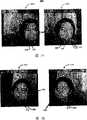
图3A示出了包括在第一立体对中捕捉的图案的第一图像和第二图像。FIG. 3A shows a first image and a second image including a pattern captured in a first stereo pair.
图3B示出了包括在第二立体对中捕捉的图案的第三图像和第四图像。Figure 3B shows a third image and a fourth image including patterns captured in the second stereo pair.
图4示出了强加在图3A-3B的图像中的一个图像上的第一条纹化图案。Figure 4 shows a first striping pattern imposed on one of the images of Figures 3A-3B.
图5示出了强加在图3A-3B的图像中的一个图像上的第二条纹化图案。Figure 5 shows a second striping pattern imposed on one of the images of Figures 3A-3B.
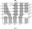
图6示出了包括一组垂直条纹和水平线的栅格。Figure 6 shows a grid comprising a set of vertical stripes and horizontal lines.
图7A-7B示出了用于在包括特定条纹的图案中对初始匹配像素进行定位的处理。7A-7B illustrate a process for locating an initially matching pixel in a pattern comprising a particular stripe.
图7C示出了包括表示被定位在图6的水平线中的一条上的像素的亮度值的曲线的亮度分布图。FIG. 7C shows a luminance distribution diagram including curves representing luminance values of pixels positioned on one of the horizontal lines of FIG. 6 .
图8示出了用于在不包括参考条纹的图案中对初始匹配像素进行定位的处理。Figure 8 illustrates a process for locating initially matching pixels in a pattern that does not include a reference stripe.
图9示出了不是条纹像素的形心像素。Figure 9 shows centroid pixels that are not stripe pixels.
图10分别示出了包括形心条纹像素和与形心条纹像素对应的像素的第一栅格和第二栅格。FIG. 10 shows a first grid and a second grid including centroid fringe pixels and pixels corresponding to centroid fringe pixels, respectively.
图11示出了用于对两个图像中的差别进行传播的处理。Figure 11 shows a process for propagating the difference in two images.
图12示出了用于对水平方向的差别进行传播的处理。Fig. 12 shows the process for propagating the difference in the horizontal direction.
图13示出了用于对垂直方向的差别进行传播的处理。Fig. 13 shows the process for propagating the difference in the vertical direction.
图14示出了用于生成具有纹理的单个三维表面模型的处理。Figure 14 shows the process for generating a single three-dimensional surface model with texture.
图15示出了用于计算初始变换矩阵的处理。Fig. 15 shows the process for calculating the initial transformation matrix.
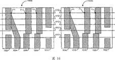
图16A-16B示出了注册之前的第一三维表面模型和第二三维表面模型。16A-16B show the first three-dimensional surface model and the second three-dimensional surface model before registration.
图17A-17B示出了图16A-16B的注册之后的第一和第二三维表面模型。17A-17B illustrate the first and second three-dimensional surface models of FIGS. 16A-16B after registration.
图18示出了没有纹理的单个三维表面模型和有纹理的单个三维表面模型。Figure 18 shows a single 3D surface model without texture and a single 3D surface model with texture.
图19示出了用于对对象的三维图像进行重构的处理。Fig. 19 shows a process for reconstructing a three-dimensional image of an object.
具体实施方式Detailed ways
参照图1,示出了三维数字化系统100的实施例,该系统包括五个相机102、104、106、108和110。这些相机被排列成两个立体对101a和101b,以及一个纹理相机106,其中,立体对101a包括相机102和104,立体对101b包括相机108和110。系统100还包括图案投影仪112、五个红外滤光器114(立体相机102、104、108和100中的每个相机上有一个红外滤光器114,图案投影仪112上有一个红外滤光器114)以及具有图案的幻灯片116。如例子所示,示出了具有垂直线图案的幻灯片116。相机102、104、106、108和110通过导线120连接到计算机处理器118。Referring to FIG. 1 , an embodiment of a three-dimensional digitizing system 100 including five cameras 102 , 104 , 106 , 108 and 110 is shown. These cameras are arranged into two stereo pairs 101a and 101b, including cameras 102 and 104, and one texture camera 106, wherein stereo pair 101a includes cameras 102 and 104, and stereo pair 101b includes cameras 108 and 110. System 100 also includes gobo projector 112, five IR filters 114 (one IR filter 114 on each of stereo cameras 102, 104, 108, and 100 and one IR filter on gobo projector 112). device 114) and a slide 116 with a pattern. As an example, a slide 116 is shown having a pattern of vertical lines. Cameras 102 , 104 , 106 , 108 , and 110 are connected to computer processor 118 by wires 120 .
三维数字化系统100能够捕捉动态或静态场景的三维信息。系统100用红外光照射对象,并且使用红外滤光器114。系统100使用投影仪112、滤光器114和幻灯片116,用希望的红外图案照射对象。投影仪112可以包括能够产生可见光谱和红外光谱中的光线的普通光源。对普通光线进行滤光,从而仅投射占优势的红外光。在另一个实施例中,投影仪可以包括没有滤光器114的红外光源。立体相机102、104、108和110中的每一个都配备有红外滤光器114中的一个,系统100使用立体相机102、104、108和110捕捉重叠的图案。此外,系统100还能够同时使用纹理相机106捕捉对象的彩色纹理。由于相机106不包括滤光器114中的一个,因此,相机106将接收全部进入光,包括可见光和红外光。但是,可见光一般比红外光强得多,因此,相机106不能在捕捉的图像上可见地示出红外图案。系统100将这些信息通过导线120发送到计算机处理器118。计算机处理器118可以使用以下描述的处理200,处理200使用该信息创建具有纹理的单个三维表面。红外发光和红外滤光器的使用提供了一种不对被拍摄的对象进行可见照明的实施例。如果对象是单个人的脸部,则由于这种图案不使人注意力分散,因此不用可见光进行照明是有利的。此外,使用红外发光和红外滤光器允许同时拍摄所有图像(取决于例如火线卡或USB接口的速度),这是因为不需要对这种图案进行打开和关闭。此外,由于不需要将图案打开和关闭,因此,除了控制相机以捕捉图像外,不需要对硬件进行附加控制就可以拍摄图像。The 3D digitization system 100 is capable of capturing 3D information of dynamic or static scenes. System 100 illuminates a subject with infrared light, and uses infrared filter 114 . System 100 uses projector 112, filter 114, and slide 116 to illuminate a subject with a desired infrared pattern. Projector 112 may include a common light source capable of producing light in the visible and infrared spectrums. Ordinary light is filtered so that only the predominantly infrared light is projected. In another embodiment, the projector may include an infrared light source without filter 114 . Each of the stereo cameras 102, 104, 108, and 110 is equipped with one of the infrared filters 114, and the system 100 uses the stereo cameras 102, 104, 108, and 110 to capture overlapping patterns. In addition, the system 100 is also capable of simultaneously using the texture camera 106 to capture the color texture of the object. Since camera 106 does not include one of filters 114, camera 106 will receive all incoming light, including visible and infrared light. However, visible light is generally much more intense than infrared light, and therefore, camera 106 cannot visibly show an infrared pattern on a captured image. System 100 sends this information to computer processor 118 over wire 120 . Computer processor 118 may use
参照图2,处理200可以使用系统100例如执行对象的三维重构。处理200包括获得图像(202)。在使用系统100的一个实施例中,作为获得图像(202)的一部分,在图案被投影到三维对象上的同时,产生第一立体图像、第二立体图像和纹理图像。第一立体图像由立体对101a产生,并且包括三维对象的第一图像和第二图像。通过在相机102捕捉经过红外滤光器114滤光的光线,产生第一图像。通过在相机104捕捉经过红外滤光器114滤光的光线,产生第二图像。第一图像包括具有图案的三维对象,并且可以是包括多个像素的二维数字图像。类似地,第二图像包括具有图案的三维对象,并且是包括多个像素的二维数字图像。第二立体图像由立体对101b产生,并且包括该三维对象的第三图像和第四图像。通过在相机108处捕捉经过红外滤光器114滤光的光线产生第三图像,并且,第三图像是包括多个像素的二维数字图像。类似地,通过在相机110处捕捉经过红外滤光器114滤光的光线产生第四图像,并且该第四图像是包括多个像素的二维数字图像。Referring to FIG. 2,
在上述的实施例中,通过在纹理相机106处捕捉未经滤光的光线产生所述三维对象的纹理图像。在不显示所述红外图案的情况下,纹理图像包括所述三维对象,并且是包括多个像素的二维数字图像。In the above-described embodiments, the texture image of the three-dimensional object is generated by capturing unfiltered light at the texture camera 106 . In the case where the infrared pattern is not displayed, the texture image includes the three-dimensional object and is a two-dimensional digital image including a plurality of pixels.
处理200包括可选择地(如由包围操作201的虚线表示的)对相机102、104、106、108和110中的一个、多个或全部进行校准(201)。作为校准(201)的一部分,可以确定和修改一个或多个、通常是多个相机参数,如外部和内部参数。外部参数包括相机相对于参考坐标系统的平移和旋转。内部参数包括相机的焦距、图像中心以及透镜失真参数。这个实施例中的校准在系统设置期间进行,并且,内部和外部参数都被存储,并且以后被用在三维重构处理中。如果相机102、104、106、108和110中的一个相对于其他相机移动,则系统100需要被重新校准。尽管不是必须要求人为输入,但是,校准一般包括人为输入。处理200中的其他操作,尤其是后续操作通常在没有人为输入的情况下自动工作。
处理200包括产生第一三维表面模型(也称为第一网格)(204)。产生第一三维表面模型(204)可以使用相机的一个或多个参数和第一立体图像。相机参数可以被用于按照本领域公知的技术对第一立体图像进行校正。作为一个实施例中的校正的一部分,外部和内部参数被用于计算与在立体对101a中捕捉的每个图像相关的3×3的校正矩阵。校正矩阵对立体对101a的两个图像进行变换,使得每个图像中的对应像素具有相同的水平位置。第一立体图像被用于建立第一图像的像素与第二图像的像素之间的第一对对应关系,第一对对应关系用于建立第一组三维点,接下来,该第一组三维点被用来产生第一三维表面模型(204)。
类似地,处理200包括产生第二三维表面模型(也称为第二网格)(206)。产生第二三维表面模型可以使用一个或多个相机参数以及第二立体图像。相机参数可以被用于按照本领域公知的技术对第二立体图像进行校正。如以上在一个实施例中所述,外部和内部参数被用于计算与在立体对101b中捕捉的每个图像相关的3×3的校正矩阵。校正矩阵对在立体对101b中捕捉的两个图像进行变换,使得每个图像中的对应像素具有相同的水平位置。第二立体图像被用于建立第三图像的像素与第四图像的像素之间的第二对对应关系,第二对对应关系用于产生第二组三维点,接下来,该第二组三维点被用来产生第二三维表面模型(206)。Similarly,
作为产生第一和第二三维表面模型的一部分(204和206),可以使用立体匹配法(stereo matching method)。一个特定的立体匹配法包括将由一组条纹组成的预定图案投影到三维对象上。所述预定图案提供了用于在第一图像的条纹像素与第二图像的条纹像素之间建立第一对对应关系的足够信息。类似地,预定图案提供了用于在第三图像的条纹像素与第四图像的条纹像素之间建立第二对对应关系的足够信息。由于条纹被用于计算对象的三维表面,因此,所述对象的被重新构成的三维图像的分辨率取决于条纹的分辨率。因此,如果被用作投影图案的一部分的条纹越多,则表面上被采样的三维点就越多,被捕捉的表面细节就越多。可以按照要被数字化的对象的复杂度来选择适当的图案。例如,细节较少的表面(例如,足球)比细节较多的表面(例如,人脸)需要更少的条纹。As part of generating the first and second three-dimensional surface models (204 and 206), a stereo matching method may be used. One particular stereo matching method involves projecting a predetermined pattern consisting of a set of stripes onto a three-dimensional object. The predetermined pattern provides sufficient information for establishing a first pair of correspondences between the striped pixels of the first image and the striped pixels of the second image. Similarly, the predetermined pattern provides sufficient information for establishing a second pair of correspondences between the striped pixels of the third image and the striped pixels of the fourth image. Since fringes are used to calculate the three-dimensional surface of the object, the resolution of the reconstructed three-dimensional image of the object depends on the resolution of the fringes. Therefore, if more fringes are used as part of the projected pattern, then more 3D points on the surface are sampled and more surface detail is captured. An appropriate pattern can be selected according to the complexity of the object to be digitized. For example, a surface with less detail (e.g., a soccer ball) requires fewer stripes than a surface with more detail (e.g., a human face).
在一个实施例中,立体匹配包括差别传播途径(disparity propagationapproach)。差别传播途径包括对在立体对101a和101b中的每一个中的两个图像中的、也称为种子的初始匹配像素进行定位。为了对初始匹配像素进行定位,参考条纹可以被用于提供锚定位置(anchoring position)。在两个图像中的每个图像中出现的参考条纹可以被当作第一匹配对条纹。在图3A-3B所示的一个这样的实施例中,参考条纹308比其他条纹306宽。在另一个实施例中,参考条纹308与其他条纹306宽度相同。In one embodiment, stereo matching includes a disparity propagation approach. The differential propagation path consists of locating initially matching pixels, also referred to as seeds, in the two images in each of the stereo pairs 101a and 101b. In order to locate the initial matching pixel, the reference stripe can be used to provide an anchoring position. The reference fringes appearing in each of the two images can be taken as the first matching pair of fringes. In one such embodiment shown in FIGS. 3A-3B , the
在定位初始匹配像素之后,如下面就图11-13更详细描述的,差别传播途径沿着一个或多个方向传播所述初始匹配像素。作为传播初始匹配像素的一部分,考虑到了出现一个或多个深度不连续的可能性。第一图像302、第二图像304、第三图像312和第四图像314当中的每个图像都包括在对象(例如图3A的脸部)的下巴/脖子表面之间的深度不连续310。深度不连续出现在具有不同深度的两个(或多个)物理表面的结合点。由于深度不连续使得差别传播途径中用于使两个图像匹配的条纹变形,因此,在对两个图像中的初始匹配像素进行传播的过程中,深度不连续导致困难。例如,如下面针对图4进一步讨论的,在对象(例如图3A的脸部)的下巴/脖子区域、脖子/衣服区域和/或鼻子区域中,深度不连续会使同一条物理条纹显示为若干断开的段。此外,如下面针对图5进一步讨论的,深度不连续会使两条条纹相互结合,并且形成一条条纹。After locating an initially matching pixel, as described in more detail below with respect to FIGS. 11-13 , a differential propagation pathway propagates the initially matching pixel along one or more directions. As part of propagating the initially matched pixels, the possibility of one or more depth discontinuities occurring is taken into account. Each of the
图4示出了在不显示图像的情况下投影到图像302、304、312和314中的一个图像上的条纹化图案400的例子。如图所示,深度不连续使包括条纹402、404和406在内的条纹化图案400变形。例如,在与被投影了图案的对象(例如,图3A的脸部)的下巴/脖子对应的区域412处条纹402断开。类似地,在与被投影了图案的对象(例如,图3A的脸部)的鼻子对应的区域414中,条纹404断开。条纹406包括与区域420相邻的端点416。区域420与被投影了图案的对象(例如,图3A的脸部)的颚部与肩部之间的空间对应。在一个实施例中,差别传播途径考虑了上述的深度不连续。例如,如下面针对图7A-7C更详细描述的,由于差别传播途径已经将条纹端点416做了标记,使得条纹端点416停止传播,因此差别传播途径不将初始匹配条纹传播过条纹端点416。FIG. 4 shows an example of a
如上所述,深度不连续还会导致两个条纹段相互连接。图5示出了在立体相机102、104、108和110中的一个相机中捕捉到的条纹化图案500的例子。与图4相同,条纹化图案500已经被投影到图像上,并且,将该图像去除,以单独显示图案500。条纹化图案500包括条纹502和504。条纹502包括条纹端点508。由于深度不连续导致条纹502在条纹端点508处断开,并且,条纹502的下段移动到条纹504的下段506。如果简单地将初始匹配的像素沿着条纹504传播,则很可能引入误匹配。这是由于,作为下面结合图11-13详细描述的差别传播的一部分,小窗口(small window)(例如,±3个像素)被用于寻找与初始匹配像素相关的最佳差别。该差别表示多个初始匹配的像素的列位置之间的差异。当初始匹配像素的列位置之间的差异最小时,产生最佳差别。但是,当深度不连续导致两个条纹线段相互连接时,最佳差别会落在搜索窗之外。因此,如果使初始匹配像素沿着具有深度不连续的条纹(例如,沿着段506)传播,则产生不正确的匹配。如以下结合图13更详细描述的,差别传播途径的一个实施例包括若干种用于解决这个问题的技术。As mentioned above, a depth discontinuity can also cause two stripe segments to connect to each other. FIG. 5 shows an example of a
如上所述,差别传播途径的实施例包括定位初始匹配像素。根据所使用图案的类型,有若干种定位初始匹配像素的方法。在一个实施例中,特定参考条纹被用于定位初始匹配像素。在图3A-3B所示的这个实施例中,被投影的图案包括比其他条纹306宽的参考条纹308,从而在图像中,参考条纹308是唯一的。因此,通过在两个图像中定位参考条纹308,实现定位所述初始匹配像素。As described above, an embodiment of the differential propagation approach includes locating initially matching pixels. Depending on the type of pattern used, there are several ways to locate the initial matching pixels. In one embodiment, specific reference stripes are used to locate initially matching pixels. In this embodiment shown in FIGS. 3A-3B , the projected pattern includes a
图6示出了包括水平线614、条纹602、604、606、608和610的栅格600,其中,水平线614也称为光栅线。条纹602、604、606、608和610为加在对象(例如图3A的脸部)上的条纹图案。条纹602,也称为参考条纹,与条纹604、606、608和610不同。参考条纹602被定位在投影图案的中心,且宽度为w’。参考条纹602的宽度w’近似为条纹604、606、608和610的宽度w的两倍。在一个实施例中,距离d等于宽度w。在另一个实施例中,距离d可以大于或小于宽度w。Figure 6 shows a
由于深度不连续,条纹602、604、606、608和610会在不同的位置处断开。例如,参考条纹602在可能与对象(例如图3A的脸部)的下巴/脖子区域对应的区域611处断开。参考条纹602还可能在对象(例如图3A的脸部)的脖子/衣服区域处断开。此外,深度不连续还可能会导致参考条纹602的段连接到另一条投影条纹的段,并且在图像中形成一条条纹。这样,深度不连续会使得难以在图像302、304、312和314中恢复完整的参考条纹。但是,观察表明,在沿着参考条纹602的任何地方都保持有“较宽的”性质。因此,在定位参考条纹602的段的过程中可以使用这个特性。Due to the depth discontinuity, the
阴影和阻塞通常会在图像中引起宽条纹,它看起来会类似参考条纹。阴影和阻塞干扰对参考条纹602的定位。差别传播途径将从在选择参考条纹602过程中所考虑的条纹中排除由阴影和阻塞造成的宽条纹。为此,在一个实施例中,差别传播途径按照赢家通吃方案(winner-takes-all schemen),对多数条纹的宽度进行估算。在本领域中,赢家通吃方案是公知的。赢家通吃方案使用投票策略(voting strategy)确定宽度w。在投票策略的基础上,每个边缘像素(例如,位于条纹的右边缘和左边缘的条纹像素)对其条纹的宽度进行投票。在一个实施例中,右边缘条纹像素查看它们最靠近的左边缘条纹像素,从而对它们的本地条纹的宽度进行投票。例如,右边缘条纹像素616查看最靠近的左边缘条纹像素618,对条纹604的宽度投一票。条纹604中的附加边缘条纹像素和所有光栅线614上的其他条纹也投一票。赢家通吃方案将所有条纹中票最多的宽度选择为多数条纹的宽度w。在选择参考条纹602的过程中,差别传播途径将宽度比宽度w大两倍的条纹从被考虑的条纹中排除,这是因为这些条纹像由阴影和阻塞引起的。Shadows and occlusions often cause wide stripes in the image, which can look like reference stripes. Shadows and occlusions interfere with the positioning of the
在被立体对101a和101b中的每一个捕捉的图像中,正在被拍照的对象(例如图3A的脸部)的特征会引起附加条纹。例如,当对象是人脸时,眉毛和面部的头发会使小条纹出现在投影的条纹图案当中。小条纹可以被称为噪声数据,并且,当使用平均值法时,噪声数据影响对宽度w的估算。平均值法使用所有光栅线614上的所有条纹的宽度的平均值来计算宽度w。因此,在平均值法中,噪声数据的宽度被用在计算宽度w的过程中。但是,赢家通吃方案通过在所有条纹中选择具有最多数票的宽度W力图避免这种噪声数据。即使噪声数据的宽度有一些票,但通常不会具有如多数条纹的宽度w的那么多票。结果是,差别传播途径通常也减小了噪声数据的影响。In the images captured by each of stereo pairs 101a and 101b, features of the subject being photographed (eg, the face of FIG. 3A) can cause additional streaks. For example, when the subject is a human face, eyebrows and facial hair can cause small fringes to appear in the projected fringe pattern. The small fringes can be referred to as noise data, and, when using the averaging method, the noise data affects the estimation of the width w. The average method uses the average of the widths of all stripes on all
在确定了宽度w之后,参考条纹602上的参考条纹像素被定位。图7A-7B示出了用于定位所述参考条纹像素和找出与在立体对101a和101b中的每一个中所捕捉的图像相关的初始匹配像素的处理700。处理700包括为每条光栅线614提取亮度分布图(702)。参照图7C,亮度分布图701包括代表定位在一条光栅线614上的像素的亮度值的曲线703。曲线703包括本地最大值703a、703b、703c和703d,本地最小值703e、703f、703g和703h,以及搜索窗705。处理700包括为每条光栅线614计算亮度分布图的本地极值(例如,本地最大值和最小值)(704)。为了计算本地最大值,使用了3个像素的搜索窗705。搜索窗705从曲线703的开始部分703i到曲线703的结束部分703j搜索曲线703,并且,每当搜索窗705中心处的像素亮度大于其相邻像素的亮度时,该中心像素的位置和亮度被存储在本地最大值数据库中。以这样的方式,确定本地最大值703a、703b、703c和703d的位置和亮度,并且将它们存储在本地最大值数据库中。与对本地最大值进行定位类似,搜索窗705从曲线703的开始部分703i到曲线703的结束部分703j搜索曲线703,并且,每当搜索窗705中心处的像素亮度小于其相邻像素的亮度时,该中心像素的位置和亮度被存储在本地最小值数据库中。以这样的方式,识别本地最小值703e、703f、703g和703h的位置和亮度。After the width w is determined, the reference stripe pixels on the
处理700还包括按照下式对k*进行定位(706),k*是关于被假设为在参考条纹上的每条光栅线614的亮度分布图中的本地最小值:
kn*=argmax(|Xi-Xj|*|((Inti+Intj)/2)-Intk|) (等式1)kn* =argmax (|Xi -Xj |*|((Inti +Intj )/2)-Intk |) (equation 1)
式中,i和j是亮度分布图的两个相邻本地最大值的下标,Xi和Xj是这两个本地最大值的位置,Inti和Intj分别为在Xi和Xj的亮度值,k是本地最大值Xi和Xj之间的本地最小值,n是光栅线614的下标。对于每条光栅线614(即对每个“n”),等式1主要找出参考条纹602上的像素。为了为每条光栅线614对参考条纹602上的像素进行定位,等式1通过将与k相邻的本地最大值之间的距离乘以本地最大值的平均值与本地最小值之间亮度差,为每个本地最小值k计算一个面积。等式1找出使这个面积最大的本地最小值k*。由于参考条纹602比其他条纹宽且暗,因而参考条纹上的像素产生最大面积,因此k*代表在参考条纹上的像素。例如,图7C示出了这样的情况,由于参考条纹为2d宽,本地最大值703b和703c之间的距离为3d,因此这个距离比其他相邻本地最大值之间的距离大。此外,由于参考条纹比其他条纹暗,因此在k*的亮度比在其他本地最小值的亮度低。In the formula, i and j are the subscripts of two adjacent localmaxima of the luminance distribution map, Xiand Xj are the positions of these two local maxima, Intiand Intj are the , k is the local minimum value between the local maximumXi and Xj , and n is the subscript of the
k*被当作每条光栅线614上的候选参考条纹像素。处理还包括将k*存储在数据库中(708)。例如,数据库可以是矢量R={kn*,n=1,2...N},它可以包括用于每条光栅线614的k*,其中,N为在立体对101a和101b中的每一个捕捉的图像中的光栅线614的数量。例如,矢量R包括多个像素626、628、630和632的位置,它们属于参考条纹602。对立体对101a和101b中的每一个的所有图像执行处理700。因此,处理700产生四个矢量R1,L、R1,R、R2,R和R2,L。R1,L、R1,R包括在立体对101a的左图像和右图像中的若干组候选参考条纹像素,其中,1指的是立体对101a,L指的是左图像,R指的是立体对101a的右图像。R2,L和R2,R包括在立体对101b的左图像和右图像中的若干组候选参考条纹像素,其中,2指的是立体对101b,L指的是左图像,R指的是立体对101b的右图像。k* is taken as a candidate reference fringe pixel on each
处理700包括使立体对101a和101b中的每一立体对的两个图像中的参考条纹像素匹配(710),以便去除被错误定位的参考条纹像素。使两个图像中的参考条纹像素匹配(710)包括使R1,L中的参考条纹像素与R1,R中具有相同光栅线614位置的对应参考条纹像素匹配。R1,L中的每个参考条纹像素应该有一个在R1,R中的匹配。如以下参照图8更详细描述的,对于每一这种匹配,使用匹配得分函数计算与R1,L中的参考条纹像素及其R1,R中对应像素相关的匹配得分,以估算匹配像素的质量。测量所述匹配得分,以用于被识别为匹配的当前像素的相邻像素(例如,±3个像素)。产生最高匹配得分的像素(例如,具有与R1,L中的参考条纹像素具有最高类似性的像素)被当作R1,L中的参考条纹像素的实际匹配。因此,在一个实施例中,计算七个匹配得分,以确定用于给定参考条纹像素的最佳匹配。这七个匹配得分包括用于R1,R中对应参考条纹像素的一个匹配得分以及用于在对应的参考条纹像素的每一侧上±3个像素的六个匹配得分。
类似地,使两个图像中的参考条纹像素匹配(710)包括使R2,L中的参考条纹像素与R2,R中具有相同光栅线位置的对应参考条纹像素匹配。如以下参考图8更详细描述的,对于每一个这种匹配计算匹配得分,以确定所述匹配像素的质量。如上所述,还测量所述匹配得分,以用于被识别为匹配的当前像素的相邻像素(例如,±3个像素)测量匹配得分。产生最高匹配得分的像素(例如,具有与R2,L中的参考条纹像素具有最高类似性的像素)被当作R2,L中的参考条纹像素的实际匹配。因此,在一个实施例中,计算七个匹配得分,以确定用于指定的参考条纹像素的最佳匹配。这七个匹配得分包括用于R2,R中的对应参考条纹像素的一个匹配得分以及用于在对应的参考条纹像素的每一侧上所述像素±3个像素的六个匹配得分。Similarly, matching (710) the reference fringe pixels in the two images includes matching the reference fringe pixels in R2,L to corresponding reference fringe pixels in R2,R having the same raster line position. As described in more detail below with reference to FIG. 8, a match score is calculated for each such match to determine the quality of the matched pixel. As described above, the match score is also measured for neighboring pixels (eg, ±3 pixels) of the current pixel identified as a match. The pixel that yields the highest match score (eg, the pixel with the highest similarity to the reference stripe pixel in R2,L ) is taken as the actual match to the reference stripe pixel in R2,L . Thus, in one embodiment, seven match scores are calculated to determine the best match for a given reference stripe pixel. The seven match scores include one match score for the corresponding reference stripe pixel in R2, R and six match scores for the pixel ±3 pixels on each side of the corresponding reference stripe pixel.
操作(710)将被错误定位的参考条纹像素去除,被错误定位的参考条纹像素是由于噪声和由对象(例如,图3A的脸部)的鼻子区域或下巴/脖子区域周围的深度不连续所导致的。例如,如果R1,L中的参考条纹像素不能找到R1,R中的它的匹配,则很可能该条纹像素不属于参考条纹602,并且将这个条纹像素从R1,L中去除。但是,如果R1,L中的参考条纹像素与R1,R中的对应参考条纹像素匹配,则这进一步表示该参考条纹像素属于参考条纹。Operation (710) removes mislocated reference fringe pixels due to noise and depth discontinuities around the nose region or chin/neck region of the subject (e.g., the face of FIG. 3A ). caused by. For example, if a reference stripe pixel in R1,L cannot find its match in R1,R , then it is likely that the stripe pixel does not belong to the
处理700还包括使用基于Ransac的平面拟合算法(Ransac-basedplane-fitting algorithm)确认参考条纹602的位置(712)。在本领域中,基于Ransac的平面拟合算法是公知的。作为确认参考条纹602的位置(712)的一部分,计算匹配参考条纹像素的三维点。基于本领域公知的立体三角测量技术(stereo triangulation),使用匹配参考条纹像素和相机参数计算所述三维点。这产生了用于沿着参考条纹602的多个位置的三维点。参考条纹602是右平面与对象(例如,图3A的脸部)的表面交叉的结果。使用光源和幻灯片116中的参考垂直线形成右平面。光源将光投射到幻灯片116中的参考垂直线的左边缘上,并且形成具有可以被描述为沿着光行进方向(即,与将与形成平面的光行进方向垂直的平面正交的矢量)的刨床(planer)的方位的左边缘垂直平面。类似地,光源将光投射到参考条纹602的右边缘和中间,并且形成右边缘垂直平面和中间垂直平面。这些平面与对象(例如,图3A的脸部)的表面的交叉形成了在立体对101a和101b中的每一个捕捉的图像中的参考条纹602的对应点。由于匹配参考条纹像素很可能位于参考条纹602的中间,因此匹配参考条纹像素的三维点应该属于中间平面。基于Ransac的平面拟合算法(Ransac-based plane-fitting algorithm,RPA)被用于找出中间平面参数(例如,中间平面的法向矢量和中间平面的位置)。操作712使用中间平面参数确定三维点到该平面的距离。不考虑距离该平面过远的三维点。即,假设距离该平面过远的点不在参考条纹上。
在确认了参考条纹602的位置之后(712),处理700包括在立体对101a和101b中的每一个所捕捉的图像中定位初始匹配像素(714)。在一个实施例中,定位初始匹配像素(714)包括对到两个图像中的匹配参考条纹像素的左边最近的边缘条纹像素进行识别。在另一个实施例中,对初始匹配像素进行定位(714)包括对到两个图像中的匹配参考条纹像素的右边最近的边缘条纹像素进行识别。例如,参照图6,到参考条纹像素626、628、630和632最近的边缘条纹像素为边缘条纹像素612、634、636和638。边缘条纹像素612、634、636和638以及在另一图像中的、它们的对应像素被识别为初始匹配像素。After the location of
如以下结合图11-13说明的,在定位初始匹配像素(714)之后,沿着在立体对101a和101b的每一个中捕捉的图像中的一个或多个方向传播所述初始匹配像素。As explained below in connection with FIGS. 11-13 , after the initial matching pixels are located ( 714 ), they are propagated along one or more directions in the images captured in each of the stereo pairs 101a and 101b.
在另一个实施例中,所使用图案的类型不包括作为参考条纹的特定条纹(例如,所有条纹具有相同的宽度)。因此,这个实施例提供了在不使用特定参考条纹的优点的情况下,对在立体对101a和101b中的每一个捕捉的图像之间的初始匹配像素进行定位的算法。基于这种方法定位的初始匹配像素不一定属于同一条纹。In another embodiment, the type of pattern used does not include a particular stripe as a reference stripe (eg, all stripes have the same width). Thus, this embodiment provides an algorithm for locating initial matching pixels between the images captured by each of the stereo pairs 101a and 101b without the advantage of using a specific reference fringe. Initial matching pixels located based on this method do not necessarily belong to the same stripe.
图8示出了根据其中所有条纹具有相同宽度的实施例的用于定位初始匹配像素的处理800。处理800包括使用平均值函数在第一对图像和第二对图像中定位与每条光栅线614相关的形心像素(802)。第一对图像包括由立体相机102产生的第一图像和由立体相机104产生的第二图像。第二对图像包括由立体相机108产生的第三图像和由立体相机110产生的第四图像。形心像素是每条光栅线614上的所有边缘条纹像素的平均值。处理800包括使用本领域公知的、作为预处理的边缘提取以及边缘链接确定形心像素是否是边缘条纹像素(806)。如果该形心像素不是边缘条纹像素,则处理800包括将离形心像素最近的边缘条纹像素设置为形心条纹像素(806和808)。例如,栅格900包括条纹902、904、906、908和910以及光栅线912。栅格900还包括位于光栅线912中的一个上的形心像素914。由于形心像素914不是边缘条纹像素,因此,作为最靠近形心像素914的边缘条纹像素916被设置为形心条纹像素。FIG. 8 illustrates a process 800 for locating initially matching pixels according to an embodiment in which all stripes have the same width. Process 800 includes locating a centroid pixel associated with each
处理800包括找出在每条光栅线614上的初始匹配像素(810)。作为找出初始匹配像素(810)的一部分,与第一图像中每条光栅线614相关的形心条纹像素与第二图像中的对应形心条纹像素相匹配。类似地,与第三图像中每条光栅线614相关的形心条纹像素与第四图像中的对应形心条纹像素相匹配。例如,可以使用与前述相同的、开始于对应位置并且在搜索窗中对最佳匹配得分进行检查的处理。Process 800 includes finding an initial matching pixel on each raster line 614 (810). As part of finding an initial matching pixel (810), the centroid fringe pixel associated with each
例如,图10示出了目的在于在第一图像和第二图像中找出初始匹配像素的栅格1000a和1000b。栅格1000a包括条纹1002、1004、1006、1008和1010以及光栅线1012。条纹1002、1004、1006、1008和1010为在立体相机102中捕捉的条纹。栅格1000a还包括形心条纹像素p和条纹像素ni和nj。形心条纹像素p在条纹1006上。条纹像素ni和nj分别在条纹1002和1008上。栅格1000b包括条纹1014、1016、1018、1020和1022以及光栅线1012。条纹1014、1016、1018、1020和1022是在立体相机104中捕捉的条纹。栅格1000b还包括形心条纹像素p’和条纹像素ni’和nj’。形心条纹像素p’在条纹1018上。条纹像素ni’和nj’分别在条纹1014和1020上。作为找出初始匹配像素的一部分,使第一栅格1000a中的形心条纹像素p与第二栅格1000b中的对应形心条纹像素p’匹配。对于像素p和p’的光栅线1012,像素p和p’被当作用于初始匹配像素的初始猜想。For example, FIG. 10
处理800包括对像素p和p’匹配得如何好进行评估(812)。作为对匹配像素p和p’的质量进行评估(812)的一部分,本地窗口(15×15)中的归一化零平均值交叉相关性(normalized zero-mean cross correlation,NZMCC)被用作匹配得分函数m(p,p’)。在本领域中,ZNMCC是公知的。由等式2表示的匹配得分函数m(p,p’)为亮度匹配得分函数mint(p,p’)和梯度匹配得分函数meg(p,p’)的线性组合。由等式3表示的亮度匹配得分函数mint(p,p’)确定包括多个像素亮度的亮度图中像素p和p’之间的类似性。由等式4表示的梯度匹配得分函数meg(p,p’)确定包括多个像素梯度的梯度图中像素p和p’之间的类似性。以下定义了匹配得分函数m(p,p’):Process 800 includes evaluating how well pixels p and p' match (812). As part of evaluating (812) the quality of matching pixels p and p', the normalized zero-mean cross-correlation (NZMCC) in a local window (15×15) is used for matching Scoring function m(p, p'). ZNMCCs are well known in the art. The matching score function m(p, p') represented by Equation 2 is a linear combination of the luma matching score function mint (p, p') and the gradient matching score function meg (p, p'). The luminance matching score function mint (p,p') represented by Equation 3 determines the similarity between pixels p and p' in a luminance map comprising a plurality of pixel luminances. The gradient matching score function meg (p,p') represented by Equation 4 determines the similarity between pixels p and p' in a gradient map comprising gradients of multiple pixels. The matching score function m(p, p') is defined as follows:
m(p,p′)=αmeg(p,p′)+(1-α)mint(p,p′) (等式2)m(p,p')=αmeg (p,p')+(1-α)mint (p,p') (equation 2)
和and
mint(p,p′)=∑Ω(I(p)-μ)*(I′(p′)-μ′)/σσ′ (等式3)mint (p, p′)=∑Ω (I(p)-μ)*(I′(p′)-μ′)/σσ′ (Equation 3)
meg(p,p′)=∑Ω(E(p)-μE)*(E′(p′)-μ′E)/σEσ′E (等式4)meg (p, p′)=∑Ω (E(p)-μE )*(E′(p′)-μ′E )/σE σ′E (equation 4)
式中,Ω为图像I中像素p周围的15×15个邻近像素,Ω′为图像I′中像素p′周围的对应邻近像素,I(p)、I′(p′)分别是在图像I和I’中p和p′处的亮度值,(μ,σ)和(μ′,σ′)分别是I和I’中的邻近像素Ω和Ω′中的平均值和标准偏差,E(p)和E′(p′)分别为梯度图E和E′中的、在p和p′的梯度值,并且,(μE,σE)和(μ′E,σ′E)分别是梯度图E和E′中的平均值和标准偏差。α为0到1之间的权重因数,并且根据其值,对等式2中的亮度或梯度匹配得分函数进行强调。在一个实施例中,α的值为0.6,从而给梯度匹配得分函数以更大的权重。In the formula, Ω is the 15×15 adjacent pixels around the pixel p in the image I, Ω' is the corresponding adjacent pixels around the pixel p' in the image I', I(p), I'(p') are the The luminance values at p and p' in I and I', (μ, σ) and (μ', σ') are the mean and standard deviation in neighboring pixels Ω and Ω' in I and I', respectively, E (p) and E′(p′) are the gradient values at p and p′ in the gradient maps E and E′ respectively, and (μE , σE ) and (μ′E , σ′E ) are respectively are the mean and standard deviation in the gradient plots E and E'. α is a weighting factor between 0 and 1, and depending on its value, either the brightness or the gradient matching score function in Equation 2 is emphasized. In one embodiment, the value of α is 0.6 to give more weight to the gradient matching score function.
等式2主要确定两个像素p和p′之间的匹配质量。有若干种用于对产生最佳匹配的边缘条纹像素p′进行定位的方法。在一个实施例中,匹配得分函数m(p,p’)被用于确定对形心条纹像素p具有最高类似性的边缘条纹像素p′。作为确定具有最高类似性的边缘条纹像素p′的一部分,为栅格1000a中的形心条纹像素p以及位于栅格1000b中的与p相同的光栅线上的所有边缘条纹像素,计算匹配得分函数m(p,p′),并且,将产生最高匹配得分的边缘条纹像素当作p的一个匹配。这个实施例不总是导致最佳匹配。由于非对应像素的匹配得分可能比对应像素的匹配得分高,也许这个实施例可能导致不正确的匹配。例如,匹配得分m(p,nj′)可能比匹配得分m(p,p′)高。因此,在这个实施例中,可能而是nj’而不是p′被选择为p的最佳匹配。Equation 2 mainly determines the matching quality between two pixels p and p'. There are several methods for locating the edge stripe pixel p' that yields the best match. In one embodiment, the matching score function m(p, p') is used to determine the edge stripe pixel p' that has the highest similarity to the centroid stripe pixel p. As part of determining the fringe pixel p' with the highest similarity, a matching score function is computed for the centroid fringe pixel p in
在另一个实施例中,匹配支持函数M被用于确定与形心条纹像素p具有最高类似性的像素p′。等式5示出了匹配支持函数M的一个实施例,它用于确定邻近边缘条纹像素(ni和ni′)以及(nj和nj′)是否具有如匹配像素p和p′那样的类似匹配得分:In another embodiment, the matching support function M is used to determine the pixel p' having the highest similarity to the centroid fringe pixel p.
M(p,p′)=∑i=1Am(ni,ni′)+∑j=1Bm(nj,nj′)(等式5)M(p, p′)=∑i=1A m(ni , ni ′)+∑j=1B m(nj , nj ′) (Equation 5)
式中,i和j分别表示p和p′的左和右边上的条纹,A是在p和p′左边条纹的数量,B是在p和p′右边上的条纹的数量。作为计算M(p,p′)的一部分,定位边缘条纹像素ni,其中,i是p左边的条纹。类似地,定位边缘条纹像素ni′,其中,i是p’左边的条纹。ni与ni′很可能是匹配的像素,因为如果p和p′匹配良好,则有理由假设边缘条纹像素ni(其中,i是栅格1000a中p左边的条纹)与边缘条纹像素ni′(其中i是栅格1000b中的p′左边的条纹)匹配。计算用于与p和p’左边每条条纹相关的ni与ni′的匹配得分,并将它们加在一起。In the formula, i and j denote the stripes on the left and right sides of p and p′ respectively, A is the number of stripes on the left side of p and p′, and B is the number of stripes on the right side of p and p′. As part of computing M(p,p'), edge fringe pixels ni are located, where i is the fringe to the left of p. Similarly, edge fringe pixels ni ' are located, where i is the fringe to the left of p'. ni and ni ' are likely matching pixels, because if p and p' are well matched, it is reasonable to assume that edge stripe pixel ni (where i is the stripe to the left of p in
类似地,作为计算M(p,p′)的一部分,定位边缘条纹像素nj,其中,j是p左边的条纹,和,定位边缘条纹像素nj′,其中,j是p′左边的条纹。nj和nj′很可能是匹配的像素,因为如果p和p′匹配良好,则有理由假设边缘条纹像素nj(其中,j是栅格1000a中p右边的条纹)与边缘条纹像素nj′(其中,j是栅格1000b中p′右边的条纹)匹配。对用于p和p′右边的每条条纹的nj和nj′的匹配得分进行计算,并将它们加在一起。如果p和p′匹配良好,则一般邻近像素的匹配得分高,导致对p和p’的高匹配支持。如果p和p′为不良匹配,则一般邻近像素的匹配得分低,导致对p和p′的低匹配支持。Similarly, as part of computing M(p,p'), locate edge stripe pixelnj , where j is the stripe to the left of p, and locate edge stripe pixelnj ', where j is the stripe to the left of p' .nj andnj ' are likely to be matching pixels, because if p and p' match well, it is reasonable to assume that edge stripe pixelnj (where j is the stripe to the right of p in
处理800包括为形心条纹像素确定最终匹配(814)。作为确定最终匹配(814)的一部分,使匹配支持函数M最大的像素p*被当作p的匹配,其中Process 800 includes determining a final match for the centroid fringe pixel (814). As part of determining the final match (814), the pixel p* that maximizes the matching support function M is taken as a match for p, where
p*=argmaxp′(M(p,p′)) (等式6)p* = argmaxp' (M(p, p')) (equation 6)
p′的范围包括栅格1000b中的位于与形心条纹像素p在同一条光栅线1012上的所有条纹像素。本质上,等式6对具有对p的最高类似性的像素进行定位。如以下针对图11-13更细描述的,如果匹配得分m(p,p*)比要求的阈值高,则将m(p,p*)当作用于差别传播处理的初始匹配像素。在一个实施例中,阈值为0.8。The range of p' includes all the fringe pixels in the
包括匹配支持函数M的实施例增强了所述匹配算法,这是因为它避免了非对应像素产生比对应像素高的匹配得分的情况。如上所述,nj′可能导致比正确的匹配p′高的匹配得分,这会导致将nj′选择为p的良好匹配。由于p和nj′为误匹配的对,因此它们的邻近条纹的边缘像素的匹配得分一般很低。因此,对p和nj′的匹配支持一般很低,表示p和nj′不是良好匹配。因此,这种方法被设计为对失配进行识别,去除失配,并且产生更可靠的匹配结果。Embodiments including the matching support function M enhance the matching algorithm because it avoids situations where non-corresponding pixels yield a higher matching score than corresponding pixels. As mentioned above,nj ' may result in a higher match score than the correct match p', which would lead to selectingnj ' as a good match for p. Since p and nj ' are mismatched pairs, the matching scores of the edge pixels of their adjacent stripes are generally very low. Therefore, the matching support for p andnj ' is generally low, indicating that p andnj ' are not a good match. Therefore, this method is designed to identify mismatches, remove mismatches, and produce more reliable matching results.
处理800继续为每条光栅线1012寻找初始匹配像素。在为所有光栅线1012找到初始匹配像素之后,处理800可以用两个附加操作,来进一步保证初始匹配像素的正确性和可靠性。这两个操作包括对初始匹配像素si和si′的本地和全局支持进行检查。初始匹配像素si和si′为一对边缘条纹像素,并且包括位置(xi,yi)和(xi′,yi′),其中,x代表列,y代表行。如上所述,由于对图像进行了校正,因此,行位置yi和yi’相同。但是,列位置xi和xi′不同。xi和xi′之间的差异被称为差别。Process 800 continues with finding an initial matching pixel for each
对初始匹配像素s i和si′的本地支持进行检查包括确定初始匹配像素si和si′的差别,并且将这个差别与位于邻近光栅线1012上的初始匹配像素nk和nk′的差别进行比较。如果初始匹配像素nk和nk′的差别与初始匹配像素si和si′的差别类似,则将位于邻近光栅线1012上的初始匹配像素nk和nk′计数为一个支持者。如果在初始匹配像素si和si′的附近的支持者的数量少于附近初始匹配像素的数量的一半,则将初始匹配像素si和si′计数为一个不良匹配或忽略。对初始匹配像素si和si′的本地支持进行检查有助于将靠近深度不连续的失配去除,这样的匹配通常没有来自来自邻近匹配的有力支持。Checking for local support of initially matched pixelssi and si' involves determining the difference between initially matched pixelssi andsi ' and comparing this difference with initially matched pixelsnk andnk ' located on
对初始匹配像素si和si′的全局支持的检查包括构成差别的直方图。为初始匹配像素的差别计算直方图,并且使用直方图对差别的分布进行分析。在直方图中,良好的差别通常表现出强支持,即,初始匹配像素中的许多具有这样的差别。同时,不良差别通常表现出弱支持,即,只有很少的初始匹配像素共享这个差别。因此,直方图有助于识别并去除具有弱支持的初始匹配像素。A check of the global support of initially matching pixels si and si ' consists of a histogram of the constituent differences. A histogram is computed for the difference of the initially matched pixels, and the distribution of the difference is analyzed using the histogram. In the histogram, good differences usually show strong support, ie, many of the initially matching pixels have such a difference. Meanwhile, bad differences usually exhibit weak support, i.e., only few initially matching pixels share this difference. Therefore, the histogram helps to identify and remove initial matching pixels with weak support.
在根据上述方法中的一个方法找出初始匹配像素之后,如针对图11-13说明的,沿着一个或多个方向,对初始匹配像素中的每一个进行传播。参照图3A-3B,差别传播被用于建立第一图像302中的附加边缘条纹像素与第二图像304中的附加边缘条纹像素之间的对应关系。类似地,差别传播还被用于建立第三图像312中的附加边缘条纹像素与第四图像314中的附加边缘条纹像素之间的对应关系。After an initial matching pixel is found according to one of the methods described above, each of the initial matching pixels is propagated along one or more directions as explained with respect to FIGS. 11-13. Referring to FIGS. 3A-3B , differential propagation is used to establish a correspondence between the additional edge streak pixels in the
图11示出了用于在图像302、304、312和314中沿着一个或多个方向进行差别传播的处理1100。处理1100包括识别投影条纹中的深度不连续(1102)。作为识别深度不连续(1102)的一部分,对每条条纹上的外部和内部终止部分进行标记,并且,当在差别传播期间遇到外部和内部终止部分时,沿着指定方向使差别传播进程停止。参照图4,外部终止部分分别包括条纹406的条纹端点416和条纹404和402的区域414和412。如上所述,条纹端点416表示在被投射了图案的对象中存在深度不连续(例如,在图3A的脸部的颌部与肩部之间)。内部终止部分包括在与另一条条纹的外部终止部分相邻的条纹上的像素。当由于深度不连续而导致两条条纹段彼此连接时,会造成内部终止部分。例如,参照图5,条纹504包括位置与条纹502的外部终止部分508相邻的像素段510。将像素段510标记为内部终止部分,并且,它使差别传播停止,这是由于像素段510周围的像素很可能表示深度不连续。因此,通过对内部终止部分进行识别和标记,操作1102试图有效地对由于深度不连续而导致的两条条纹相互连接的情况进行处理。FIG. 11 shows a
处理1100包括用于在由立体对101a和101b中的每一个所捕捉的图像中的附加像素之间建立对应关系的三个差别传播处理(1104、1106和1108)。第一处理包括沿着水平方向传播差别(例如,沿着左、右两个方向横穿条纹)(1104)。第二处理包括沿着垂直方向传播差别(例如,沿着上、下两个方向顺着条纹)(1106)。第三处理包括再次沿着水平方向传播差别(例如,沿着左、右两个方向横穿条纹)(1108)。
图12示出了用于在第一处理中沿着水平方向传播差别的处理1200。处理1200包括对每条光栅线614上的每个初始匹配像素的差别进行计算(1202)。某些光栅线614会由于深度不连续而导致没有初始匹配像素。FIG. 12 shows a
如上所述,由于对图像进行了校正,因此,每个图像中的对应像素具有相同的光栅线位置和可能不同的列位置。因此,沿着初始匹配像素的光栅线614进行找到初始匹配像素的邻近像素的对应关系。处理1200包括向参考图像中的每条光栅线614上的初始匹配像素的左边传播差别(1204)。用于立体对101a的参考图像可以是第一图像302或第二图像304。用于立体对101b的参考图像可以是第三图像312或第四图像314。在一个实施例中,将第一图像302当作用于立体对101a的参考图像,并且将第三图像312当作用于立体对101b的参考图像。参照图6,作为向左传播差别(1204)的一部分,在参考图像中,对初始匹配像素612左边的边缘条纹像素616进行定位。向左传播差别(1204)还建立参考图像中的边缘条纹像素616与另一个图像中的对应像素之间的对应关系。为了建立参考图像中的边缘条纹像素616与另一个图像中的对应像素之间的对应关系,使用在操作1202中计算的初始匹配像素612的差别。初始匹配像素612的差别提供了对另一个图像中的对应像素的初始猜测。因此,将具有这样的位置的像素616′(没有示出)当作用于边缘条纹像素616的初始匹配。确定用于匹配像素(616,616′)的匹配得分。此外,还确定用于条纹像素616与像素616′的若干邻近像素(例如,±3个像素)中的每个像素的匹配得分。导致最高匹配得分(例如,与边缘条纹像素616具有最高类似性)的像素被当作条纹像素616的实际匹配。将最高匹配得分与阈值进行比较,并且,如果最高匹配得分高于阈值,则认为该匹配为良好匹配(1206)。如果最高匹配得分低于阈值,则认为该匹配为不良匹配(1206)。如果如由低匹配得分表示的,有三个连续的、没能找到匹配的像素,则差别传播将被停止(1208)。例如,可以使用NZMCC计算匹配得分。As described above, due to the rectification of the images, corresponding pixels in each image have the same raster line position and possibly different column positions. Accordingly, finding correspondences of neighboring pixels of the initially matched pixel is performed along the
如果匹配是成功的,则处理1200包括为新匹配的像素计算差别,并且将这个差别设置为默认差别(1212)。向初始匹配像素的左边传播差别还包括将参考图像中的下一个边缘条纹像素618定位到在前边缘条纹像素616的左边,并且建立参考图像中的边缘条纹像素618与另一个图像中的对应像素之间的对应关系(1214)。为了建立边缘条纹像素618与对应像素之间的对应关系,以与操作1204类似的方式,使用新的默认差别找出用于条纹像素618的对应关系。差别传播从新匹配的像素继续进行,并且,当边缘条纹像素属于条纹的外部或内部端点时,差别传播停止。If the match was successful,
在完成向初始匹配像素的左边进行差别传播之后,还以同样方式向初始匹配像素的右边进行差别传播。对每条光栅线614重复处理1200。因此,处理1200在立体对101a和101b中的每一个捕捉的图像中提供了一组匹配的水平带,其中,猜测匹配带跟在条纹的边缘的后面。After completing differential propagation to the left of the initial matching pixel, differential propagation is also performed to the right of the initial matching pixel in the same manner.
图13示出了用于在第二处理中沿着垂直方向传播所述差别的处理1300。根据在前的水平差别传播,多数条纹可以具有它们匹配边缘的一部分。例如,参照图6,参考条纹602包括不匹配的段N和匹配的边缘条纹像素634和638。处理1300包括为条纹化图案中的每个条纹边缘,对参考图像中的不匹配段N进行定位(1302)。不匹配段N包括端点N1和N2。处理1300包括对位于端点N1之上的匹配边缘条纹像素634以及位于端点N2之下的匹配边缘条纹像素638进行定位(1304)。处理1300包括对匹配边缘条纹像素634和638的差别进行比较(1306)。如果匹配边缘条纹像素634和638的差别之间的差异在阈值之上,则不沿着参考条纹602传播差别(1307和1308)。并且,将这个段标记为不定段。在一个实施例中,阈值为3。如果匹配边缘条纹像素634和638的差别之间的差异在阈值之下(例如,小于3),则处理1300包括根据匹配边缘条纹像素634和638的差别,找出参考图像中的不匹配段N与另一个图像中的对应段之间的对应关系(1307和1310)。在一个实施例中,为了找出两个图像中的不匹配段N之间的对应关系,从段N的中心向两个端点N1和N2进行传播。或者,可以从段N的顶部到底部进行传播,反之亦然。对其他条纹604、606和608重复处理1300。在一个实施例中,处理1300可以从条纹化图案的左上角开始,并且移动到条纹化图案的右下角。或者,处理1300可以从条纹化图案的右上角开始,并且移动到条纹化图案的左下角。因此,可以使每条条纹中的不匹配段N与另一图像中的对应段匹配。FIG. 13 shows a process 1300 for propagating the differences along the vertical direction in a second process. Depending on the previous horizontal differential propagation, most stripes may have a portion of their matching edge. For example, referring to FIG. 6 ,
在差别传播的在前两个迭代之后,可以执行第三处理。第三处理试图使诸如上面针对第二处理提到的那些不定段的不匹配条纹段匹配。第三处理使用与第一处理中的处理相同的处理(处理1200)。到目前为止的不匹配条纹可以具有在第二处理中被匹配的水平邻近像素,并且,新匹配的邻近像素可以提供能够使到目前为止的不匹配像素匹配的差别值。After the first two iterations of differential propagation, a third process may be performed. The third process attempts to match non-matching stripe segments such as those mentioned above for the second process indefinitely. The third processing uses the same processing as that in the first processing (processing 1200). The hitherto unmatched streaks may have horizontal neighbors that were matched in the second process, and the newly matched neighbors may provide a difference value that enables the hitherto unmatched pixels to match.
在第三处理之后,可以得到表示哪一个边缘条纹像素被匹配的最终匹配图。经过传播处理1200和1300,用于找到与每个条纹像素相关的对应关系的搜索空间已经很小(例如,±3个像素)。因此,差别传播途径减少了计算需求。在没有差别传播途径的情况下,使第一图像中的像素与第二图像中的对应像素匹配可能需要沿着第二图像中的光栅线614的很大的搜索窗口,以找到对应像素。这是因为可能需要对沿着第二图像中的光栅线614的多数像素进行评估,以为第一图像中的像素找到潜在匹配。因此,用于每个像素的搜索窗口通常比差别传播途径中的搜索窗口大得多,导致更高的计算需求。After the third process, a final matching map indicating which edge stripe pixels were matched can be obtained. After the
参照图11,的目前为止已经建立的匹配为整数精度。与对象的近似平整表面对应的匹配像素可能具有相同的整数差别。在三维图像中,这些匹配像素出现在相同的深度,即使它们在对象中有略微不同的深度。因此,重新构成的三维图像也许是不平滑和不连续的,这是因为,在整数差别的情况下,一般只能在深度差异相当大的匹配像素之间表现出对象深度方面的过渡。这会产生阶梯式重构。为了构成平滑并且连续的表面(1110),在一个实施例中,处理1100还包括使匹配细化到次像素精度。次像素精度提高了深度差别的分辨率;因此,在重构的三维图像中,与近似平坦的表面对应的匹配像素显现它们实际的对应深度。作为将匹配细化到次像素精度的一部分,使用了抛物线拟合法(curve-parabola-fitting method)。按照抛物线拟合法,如以上针对图8描述的,如果按照匹配得分m0将像素(x,y)匹配到(x′,y),则还使用等式2计算(x,y)与(x′-1,y)之间的匹配得分m1以及(x,y)与(x′+1,y)之间的匹配得分m2。作为构成平滑并且连续表面(1110)的一部分,将抛物线拟合到三个点(x′-1,m1)(x′,m0)和(x′+1,m2)中,并且,对抛物线上的最大值m*和对应的x*进行定位。将匹配像素(x*,y)当作对(x,y)的最终匹配。使用次像素精度的匹配,操作1110产生平滑的三维表面。Referring to Figure 11, the matches that have been established so far are integer precision. Matching pixels corresponding to approximately flat surfaces of objects may have the same integer difference. In a 3D image, these matching pixels appear at the same depth even though they have slightly different depths in the object. Consequently, the reconstructed 3D image may be non-smooth and discontinuous, since, in the case of integer differences, transitions in depth of objects can generally only be exhibited between matching pixels with relatively large depth differences. This produces a stepwise refactoring. To construct a smooth and continuous surface (1110), in one embodiment,
在最终的匹配图中,偶尔有一些误匹配像素,它们将其自己表现为表面上的尖刺。处理1110包括执行误匹配检测,以去除误匹配像素(1112)。可以在三维网孔的基础上进行检测,后面将针对图14对此进行描述。对于每个匹配像素,对邻近的像素进行定位,并且,使用立体三角测量技术(stereotriangulation technique)为匹配像素及其邻近像素计算对应的三维点。如果匹配像素的对应三维点以及其邻近像素的对应三维点之间的距离大于预定阈值,则处理1100将该匹配像素当作误匹配像素。例如,假设qi,j(j=1,2,...Ni)为pi的邻近像素,即考虑当中的像素,那么Qi,j与Pi为对应三维点。然后,处理1100为每个j确定Qi,j与Pi之间的距离是否大于预定阈值。如果Pi的大距离的邻近像素的数量对Pi的邻近像素的总数量的比值较大,则处理1100将此作为误匹配导致的点。In the final matching map, there are occasional mis-matching pixels that manifest themselves as spikes on the surface.
图14示出了用于生成具有纹理的单个三维表面模型的处理1400。处理1400包括为立体对101a和101b中的每一个生成三维点云(pointcloud)(1402)。生成三维点云可以使用立体三角测量。本领域公知的立体三角测量使用匹配像素的差别和相机参数计算三维点云。FIG. 14 shows a
处理1400包括生成和平滑用于立体对101a和101b中的每一个的三维表面模型(1404)。根据诸如三维网格划分的公知技术,使用所述三维点云生成用于立体对101a和101b中的每一个的三维表面模型。
在一个实施例中,作为生成三维表面模型的一部分,将本领域公知的三角剖分(Delaunay triangulation)算法被用于建立与参考图像中的匹配像素相关的三角测量。然后,对应的三维点形成三维网格。In one embodiment, as part of generating the three-dimensional surface model, a Delaunay triangulation algorithm known in the art is used to create a triangulation relative to matching pixels in the reference image. Then, the corresponding 3D points form a 3D mesh.
由于立体匹配处理以及立体三角测量中的数字误差,三维点云通常是有噪声的。此外,由于匹配像素是从条纹中提取的,因此三维网格通常是不规则的,当条纹被投影的表面上时,深度不连续导致条纹变形。因此,网格中的三角形在形状和尺寸方面差异很大。因此,一个实施例包括建立新的、符合指定分辨率的图像栅格的三维表面模型(例如,网格)。3D point clouds are often noisy due to the stereo matching process as well as numerical errors in stereo triangulation. Furthermore, since the matching pixels are extracted from the stripes, the 3D mesh is usually irregular, and the depth discontinuities cause the stripes to deform when the stripes are projected onto the surface. As a result, the triangles in the mesh vary widely in shape and size. Thus, one embodiment includes building a new three-dimensional surface model (eg, mesh) conforming to an image grid of a specified resolution.
在建立新的三维表面模型的过程中,作为本领域的标准进程,将矩形栅格强加在图像平面上。使用Kalman滤波和平滑,对新的三维表面模型进一步进行处理。在本领域中,这个进程是公知的。作为重新进行网格划分以及Kalman滤波和平滑的结果,产生三维表面模型,其对应的二维表面模型符合图像栅格,噪声被抑制,表面被平滑。必要时,通过将NURB表面拟合到在上述处理中得到的三维点云中,可以进一步进行平滑,在本领域中,这是公知的。In building a new 3D surface model, a rectangular grid is imposed on the image plane as a standard procedure in the field. The new 3D surface model is further processed using Kalman filtering and smoothing. This procedure is well known in the art. As a result of re-meshing and Kalman filtering and smoothing, a 3D surface model is generated whose corresponding 2D surface model fits the image grid, noise is suppressed, and the surface is smoothed. Further smoothing can be performed, if necessary, by fitting a NURB surface to the 3D point cloud obtained in the above process, as is well known in the art.
参照图14,操作(1404)产生两个三维表面模型(用于立体对101a和101b中的每一个)。处理1400使用这两个三维表面模型为立体对101a和101b生成单个合成三维表面模型(1406)。Referring to Figure 14, operation (1404) generates two three-dimensional surface models (for each of stereo pairs 101a and 101b).
参照图2,生成单个合成三维表面模型(1406)包括对第一和第二三维表面模型进行注册(208)。在本领域中,对第一和第二三维表面模型进行注册是公知的。注册指的是对来自立体对101a和101b的数据进行对准的进程,其中,来自立体对101a和101b的数据可以具有它们自己的坐标系统,因此可以将数据变换到单个坐标系统中。即使当使用相同的参照系统对立体对101a和101b进行校准时,由于校准进程中的误差或者立体对101a和101b本身中的误差,依据立体对101a和101b获得的数据可能有差异性。Referring to FIG. 2, generating a single composite three-dimensional surface model (1406) includes registering (208) the first and second three-dimensional surface models. Registration of first and second three-dimensional surface models is known in the art. Registration refers to the process of aligning the data from the stereo pair 101a and 101b, which may have their own coordinate system, so that the data can be transformed into a single coordinate system. Even when stereo pairs 101a and 101b are calibrated using the same reference system, there may be discrepancies in the data obtained from stereo pairs 101a and 101b due to errors in the calibration process or errors in stereo pairs 101a and 101b themselves.
注册第一和第二三维表面模型(208)包括将第一三维表面模型与第二三维表面模型对准。在一个实施例中,为了将第一与第二三维表面模型对准,计算第一与第二三维表面模型之间的刚性变换矩阵(R,t),因而,通过将这个矩阵应用于第一或第二三维表面模型,使一个三维表面模型与另一个三维表面模型对准。Registering (208) the first and second three-dimensional surface models includes aligning the first three-dimensional surface model with the second three-dimensional surface model. In one embodiment, to align the first and second 3D surface models, a rigid transformation matrix (R, t) between the first and second 3D surface models is computed, thus, by applying this matrix to the first or a second 3D surface model, aligning one 3D surface model with another 3D surface model.
计算刚性变换矩阵(R,t)可以包括两项操作。首先,计算初始变换矩阵,它粗略地使两个三维表面模型对准。其次,使用迭代最近点(IterativeClosest Point,ICP)将初始变换矩阵反复细化,并且最终将第一与第二三维表面模型对准。Computing the rigid transformation matrix (R, t) may involve two operations. First, an initial transformation matrix is computed, which roughly aligns the two 3D surface models. Second, the initial transformation matrix is repeatedly refined using Iterative Closest Point (ICP), and finally the first and second 3D surface models are aligned.
参照图15,处理1500可以被用于计算初始变换矩阵。处理1500包括识别第一和第二三维表面模型中感兴趣的部分(1502)。参照图3A-3B,由于每台相机在不同位置,因此,在立体对101a和101b中的每一个中捕捉的图像不覆盖正好相同的物理表面区域。每个图像都有与其他图像重叠的区域,并且,每个图像也都有仅被该图像覆盖的区域。在图3A-3B中,重叠区域包括覆盖人脸鼻子的区域。因此,在第一和第二三维表面模型中,可以将覆盖鼻子的区域选择为感兴趣的区域。由于三角测量技术被用于创建第一和第二三维表面模型,因此第一和第二三维表面模型中的每个点都被一个三角形覆盖。对应于鼻子的三角形被识别为落入中心区域中的三角形,也被称为种子三角形,并且最靠近相机。Referring to FIG. 15,
处理1500包括对感兴趣的区域进行扩展(1504)。作为对感兴趣的区域进行扩展的一部分,对与种子三角形共享相同边缘的三角形进行定位。通过对与已经在感兴趣的区域中的共享边缘的更多三角形进行处理,使扩展继续,直到这群三角形的总面积达到预定量。在一个实施例中,预定面积为10000mm2。因此,对感兴趣的区域进行扩展(1504)产生了两个区域,这给出了两个三维表面模型之间的粗略对应关系。
处理1500还包括找出第一与第二三维表面模型之间的初始变换矩阵(1506)。找出初始变换矩阵基于以上找到的两个感兴趣的区域。假设两个匹配区域中的顶分别为RG1={p1i,i=1,2,...n1}和RG2={p2j,i=1,2,...n2},式中,n1和n2分别为两个区域中的顶的数量。RG1和RG2被用于计算初始平移矢量T0和初始旋转矩阵R0。计算RG1和RG2的形心C1和C2,并且,T0=C1-C2。假设M1,cov和M2,cov为RG1和RG2的共变矩阵(covariance matrices)。然后,这两个矩阵的特征向量被用于形成初始旋转矩阵R0,它们是两个点集关于球坐标系统的旋转矩阵。然后,按照R0=R2*R-11对RG1和RG2之间的初始旋转矩阵进行估算。R0为两个点云之间的初始旋转矩阵。那么,初始变换矩阵M0包括初始平移矢量T0和初始旋转矩阵R0(M0={T0,R0})。
然后,使用ICP算法,它将M0当作初始值,并且对M0进一步进行细化。ICP的输出最终使两个三维表面模型对准。Then, using the ICP algorithm, it takes M0 as the initial value, and further refines M0 . The output of the ICP ultimately aligns the two 3D surface models.
参照图16A-16B,示出了注册之前的第一三维表面模型1601和第二三维表面模型1602。参照图16A,第一三维表面模型1601和第二三维表面模型1602以白黑形式出现,并且,每个都包括黑白条纹。第一三维表面模型1601用灰度级较轻的线表示,如在“下巴”下面示出的,并且用标号1601表示的那些线。第二三维表面模型1602用灰度级较重的线表示,如在“下颏”上面示出的,并且用标号1602表示的那些线。在注册之前,第一三维表面模型1601和第二三维表面模型1602的条纹出现在不同位置。例如,第一和第二三维表面模型的参考条纹1603相互靠近,而不是在相同位置。因此,条纹之间的间隙非常小,并且,条纹化图案没有区别。参照图16B,第一三维表面模型1601以蓝颜色出现,而第二三维表面模型1602以黄颜色出现。注册之前,黄色条纹出现在蓝色条纹之间。16A-16B, a first three-
图17A-17B示出了注册之后的第一三维表面模型1601和第二三维表面模型1602。参照图17A,第一三维表面模型1601和第二三维表面模型1602以黑白形式出现。如以上针对图16A描述的,第一三维表面模型1601用灰度级较轻的线表示,如在“下巴”下面示出的,并且用标号1601表示的那些线。第二三维表面模型1602用灰度级较重的线表示,如在“下颏”上面示出的,并且用标号1602表示的那些线。如图所示,注册使第一三维表面模型1601的垂直条纹与第二三维表面模型1602的垂直条纹对准。例如,两个三维表面模型1601和1602中的参考条纹1603重叠,并且形成区别比图16A-16B中的区别大的条纹。因此,在图17A-17B中,条纹之间的间隙比图16A-16B中示出的条纹之间的间隙大。参照图17B,第一三维表面模型1601和第二三维表面模型1602以彩色形式出现。第一三维表面模型1601以蓝颜色出现,而第二三维表面模型1602以黄颜色出现。注册之后,蓝色和黄色条纹相互重叠,产生了条纹之间的大空隙,并且使条纹化图案区别更大。例如,图17A-17B中示出的下巴区域1605比图16A-16B中示出的好。17A-17B show the first three-
再参照图2,对第一和第二三维表面模型进行合成(210)的操作将经过注册的第一和第二三维表面模型组合,并且生成单个表面模型2202,如图18所示。在本领域中,对第一和第二三维表面模型进行合成(210)的操作是公知的。Referring again to FIG. 2 , the operation of synthesizing ( 210 ) first and second three-dimensional surface models combines the registered first and second three-dimensional surface models and produces a
再参照图2,处理200包括给经过合成的三维表面模型提供纹理(212)。在本领域中,给经过合成的三维表面模型提供纹理是公知的。在一个实施例中,作为给经过合成的三维表面模型提供纹理的一部分,使用了相机参数、来自纹理相机106的图像以及经过合成的三维表面模型。由于经过合成的三维表面模型与纹理相机106在同一个坐标系统中,因此简单地将该表面模型中的每个三维点投影到图像平面上,从而产生纹理坐标。因此,给经过合成的三维表面模型提供纹理(212)产生了具有纹理的单个三维表面(1508)。例如,通过操作214和216,通过提供(214)或输出(216)具有纹理的单个三维表面,给用户提供具有纹理的单个三维表面。参照图20,示出了最终被纹理化的表面模型2204的三个视图。Referring again to FIG. 2,
参照图19,在另一个实施例中,处理1900包括将红外图案投影到三维对象上(1902),并且在图案被投影到三维对象上的同时,产生第一图像和第二图像(1904)。通过在相机102捕捉通过红外滤光器114滤光的光线,可以产生第一图像。通过在相机104捕捉通过红外滤光器114滤光的光线,可以产生第二图像。第一图像包括具有图案的三维对象,并且可以是包括多个像素的二维数字图像。类似地,第二图像包括具有图案的三维对象,并且可以是包括多个像素的二维数字图像。处理1900包括建立在第一图像的一部分像素与第二图像的一部分像素之间的第一对对应关系(1906)。Referring to FIG. 19, in another embodiment, process 1900 includes projecting an infrared pattern onto a three-dimensional object (1902), and generating a first image and a second image while the pattern is projected onto the three-dimensional object (1904). By capturing at camera 102 light filtered through infrared filter 114 , a first image may be generated. By capturing at camera 104 light filtered through infrared filter 114 , a second image may be generated. The first image includes a three-dimensional object having a pattern, and may be a two-dimensional digital image including a plurality of pixels. Similarly, the second image includes a three-dimensional object having a pattern, and may be a two-dimensional digital image including a plurality of pixels. Process 1900 includes establishing a first pair of correspondences between a portion of pixels of the first image and a portion of pixels of the second image (1906).
处理1900包括在图案被投影到三维对象上的同时产生三维对象的第三图像(1908)。在一个实施例中,第三图像可以是纹理图像,并且通过在相机106对未经滤光的光线进行捕捉产生第三图像。纹理图像包括不显露红外图案的三维对象,并且可以是包括多个像素的二维数字图像。处理1900包括根据第一对对应关系和第三图像构成二维图像(1910)。Process 1900 includes generating a third image of the three-dimensional object while the pattern is projected onto the three-dimensional object (1908). In one embodiment, the third image may be a texture image, and the third image is generated by capturing unfiltered light at the camera 106 . Texture images include three-dimensional objects that do not reveal infrared patterns, and may be two-dimensional digital images that include multiple pixels. Process 1900 includes composing a two-dimensional image from the first pair of correspondences and the third image (1910).
可以在各种装置中,至少部分实现实施例或者实施例的特性。例如,光盘(CD)、处理装置或者计算机可读介质可以包含用于实现所公开的方法中的任何一个方法的程序、指令或代码段。此外,可以为实现所公开的方法中的任何一个方法提供工具。例如,工具可以包括处理器、计算机、可编程逻辑器件或者集成电路。The embodiments or the features of the embodiments may be at least partially implemented in various apparatuses. For example, a compact disc (CD), processing device or computer readable medium may contain programs, instructions or code segments for implementing any of the disclosed methods. Additionally, means may be provided for implementing any of the disclosed methods. For example, a means may include a processor, computer, programmable logic device, or integrated circuit.
还可以使用便携式装置实现实施例。例子包括:便携式计算机或其他处理装置;移动电话、个人数字助理;消息接发装置,如纸式或便携式e-mail装置(如Blackberry);便携式音乐播放器,如iPod;或者其他电子的、便携式的、用于接发消息、娱乐、组织或游戏的装置。Embodiments may also be practiced using portable devices. Examples include: portable computers or other processing devices; mobile phones, personal digital assistants; messaging devices, such as paper or portable e-mail devices (such as Blackberry(R); portable music players, such as iPod(R); or other electronic , a portable device for messaging, entertainment, organization or gaming.
尽管公开的实施例将垂直的条纹化图案投影到三维对象(例如,图3A的脸部)上,但是,也可以将其他图案投影到三维对象上。例如,可以将水平线图案、对角线图案和/或同心圆投影到三维对象上。Although the disclosed embodiment projects a vertical striped pattern onto a three-dimensional object (eg, the face of FIG. 3A ), other patterns may also be projected onto the three-dimensional object. For example, a pattern of horizontal lines, a pattern of diagonal lines, and/or concentric circles may be projected onto the three-dimensional object.
最后,为了产生实施例,可以使用、组合和修改各种技术,例如,这些技术包括各种硬件、软件、固件、集成元件、分立元件、处理装置、存储器或存储装置、通信装置、透镜、滤光器、显示装置和投影装置。Finally, various technologies including, for example, various hardware, software, firmware, integrated components, discrete components, processing devices, memory or storage devices, communication devices, lenses, filters, etc., may be used, combined and modified in order to produce the embodiments. optical device, display device and projection device.
此外,尽管在构成人脸的3D图像的上下文中,已经一般地对公开的系统和方法进行了描述,但是,预期还能够构成其他对象的3D图像。Furthermore, although the disclosed systems and methods have generally been described in the context of composing 3D images of human faces, it is contemplated that 3D images of other objects can also be constructed.
已经对若干实施例进行了描述。然而,应该理解,可以进行各种修改。例如,为了产生另外的实施例,可以对不同系统、处理和其他实施例的要素进行组合、补充、修改、重新布置或去除。此外,为了产生实施例,可以使用、组合和修改各种技术,例如,这些技术包括各种硬件、软件、固件、集成元件、分立元件、处理装置、存储器或存储装置、通信装置、透镜、滤光器、显示装置和投影装置。因此,其他实施例在以下的权利要求的范围内。Several embodiments have been described. However, it should be understood that various modifications may be made. For example, elements of different systems, processes, and other embodiments may be combined, supplemented, modified, rearranged, or removed to create additional embodiments. In addition, various technologies including, for example, various hardware, software, firmware, integrated components, discrete components, processing devices, memory or storage devices, communication devices, lenses, filters, etc., may be used, combined and modified in order to produce the embodiments. optical device, display device and projection device. Accordingly, other embodiments are within the scope of the following claims.
Claims (23)
Translated fromChineseApplications Claiming Priority (2)
| Application Number | Priority Date | Filing Date | Title |
|---|---|---|---|
| US64175205P | 2005-01-07 | 2005-01-07 | |
| US60/641,752 | 2005-01-07 |
Publications (1)
| Publication Number | Publication Date |
|---|---|
| CN101198964Atrue CN101198964A (en) | 2008-06-11 |
Family
ID=36648180
Family Applications (1)
| Application Number | Title | Priority Date | Filing Date |
|---|---|---|---|
| CNA200680007575XAPendingCN101198964A (en) | 2005-01-07 | 2006-01-09 | Creating three-dimensional images of objects using infrared pattern illumination |
Country Status (5)
| Country | Link |
|---|---|
| US (6) | US7430312B2 (en) |
| EP (1) | EP1851527A2 (en) |
| JP (1) | JP2008537190A (en) |
| CN (1) | CN101198964A (en) |
| WO (1) | WO2006074310A2 (en) |
Cited By (19)
| Publication number | Priority date | Publication date | Assignee | Title |
|---|---|---|---|---|
| CN102194249A (en)* | 2011-05-19 | 2011-09-21 | 北京航空航天大学 | Water current modeling data capturing device with combination of infrared rays and visible light |
| CN102236911A (en)* | 2010-03-17 | 2011-11-09 | 卡西欧计算机株式会社 | 3d modeling apparatus and 3d modeling method |
| CN102246201A (en)* | 2008-12-12 | 2011-11-16 | 松下电器产业株式会社 | Image processing device and image processing method |
| CN102565871A (en)* | 2010-10-18 | 2012-07-11 | 洛克威尔自动控制技术股份有限公司 | Time of flight (tof) sensors as replacement for standard photoelectric sensors |
| CN102693005A (en)* | 2011-02-17 | 2012-09-26 | 微软公司 | Providing an interactive experience using a 3D depth camera and a 3D projector |
| CN103402382A (en)* | 2010-10-22 | 2013-11-20 | 奥达塞斯工业自动控制和信息学有限公司 | System of visual markers for fastening and digitising garment patterns, and method for digitising garment patterns using said visual markers |
| CN103888674A (en)* | 2014-04-15 | 2014-06-25 | 华晶科技股份有限公司 | Image capture device and image capture method |
| CN104285128A (en)* | 2012-05-24 | 2015-01-14 | 高通股份有限公司 | Emission of Affine Invariant Spatial Masks for Active Depth Sensing |
| CN104685868A (en)* | 2012-10-05 | 2015-06-03 | 高通股份有限公司 | Method and apparatus for calibrating an imaging device |
| CN105451009A (en)* | 2014-06-13 | 2016-03-30 | 联想(北京)有限公司 | Information processing method and electronic equipment |
| CN102565871B (en)* | 2010-10-18 | 2016-12-14 | 洛克威尔自动控制技术股份有限公司 | The time-of-flight sensor replaced as standard photoelectric sensor |
| US9597587B2 (en) | 2011-06-08 | 2017-03-21 | Microsoft Technology Licensing, Llc | Locational node device |
| CN107615279A (en)* | 2015-04-02 | 2018-01-19 | 海德龙斯有限公司 | Virtual three-dimensional model generation based on virtual hexahedron model |
| CN108353158A (en)* | 2015-11-11 | 2018-07-31 | 三星电子株式会社 | Image capturing device and its control method |
| CN109003676A (en)* | 2017-06-06 | 2018-12-14 | 苏州笛卡测试技术有限公司 | A kind of Dental Aesthetic design method and device |
| CN109307478A (en)* | 2017-07-28 | 2019-02-05 | 波音公司 | The resolution ratio adaptive mesh that 3-D for executing object is measured |
| US10346529B2 (en) | 2008-09-30 | 2019-07-09 | Microsoft Technology Licensing, Llc | Using physical objects in conjunction with an interactive surface |
| CN112581512A (en)* | 2019-09-27 | 2021-03-30 | 鲁班嫡系机器人(深圳)有限公司 | Image matching, 3D imaging and posture recognition method, device and system |
| CN113343917A (en)* | 2021-06-30 | 2021-09-03 | 上海申瑞继保电气有限公司 | Histogram-based substation equipment identification method |
Families Citing this family (456)
| Publication number | Priority date | Publication date | Assignee | Title |
|---|---|---|---|---|
| US8352400B2 (en) | 1991-12-23 | 2013-01-08 | Hoffberg Steven M | Adaptive pattern recognition based controller apparatus and method and human-factored interface therefore |
| US7904187B2 (en) | 1999-02-01 | 2011-03-08 | Hoffberg Steven M | Internet appliance system and method |
| US6990639B2 (en) | 2002-02-07 | 2006-01-24 | Microsoft Corporation | System and process for controlling electronic components in a ubiquitous computing environment using multimodal integration |
| US7665041B2 (en) | 2003-03-25 | 2010-02-16 | Microsoft Corporation | Architecture for controlling a computer using hand gestures |
| US8745541B2 (en) | 2003-03-25 | 2014-06-03 | Microsoft Corporation | Architecture for controlling a computer using hand gestures |
| US7983835B2 (en) | 2004-11-03 | 2011-07-19 | Lagassey Paul J | Modular intelligent transportation system |
| JP2008537190A (en)* | 2005-01-07 | 2008-09-11 | ジェスチャー テック,インコーポレイテッド | Generation of three-dimensional image of object by irradiating with infrared pattern |
| JP5631535B2 (en) | 2005-02-08 | 2014-11-26 | オブロング・インダストリーズ・インコーポレーテッド | System and method for a gesture-based control system |
| US7697827B2 (en) | 2005-10-17 | 2010-04-13 | Konicek Jeffrey C | User-friendlier interfaces for a camera |
| US9075441B2 (en)* | 2006-02-08 | 2015-07-07 | Oblong Industries, Inc. | Gesture based control using three-dimensional information extracted over an extended depth of field |
| US8370383B2 (en) | 2006-02-08 | 2013-02-05 | Oblong Industries, Inc. | Multi-process interactive systems and methods |
| US9823747B2 (en) | 2006-02-08 | 2017-11-21 | Oblong Industries, Inc. | Spatial, multi-modal control device for use with spatial operating system |
| US8537111B2 (en)* | 2006-02-08 | 2013-09-17 | Oblong Industries, Inc. | Control system for navigating a principal dimension of a data space |
| US8531396B2 (en)* | 2006-02-08 | 2013-09-10 | Oblong Industries, Inc. | Control system for navigating a principal dimension of a data space |
| US9910497B2 (en) | 2006-02-08 | 2018-03-06 | Oblong Industries, Inc. | Gestural control of autonomous and semi-autonomous systems |
| US8537112B2 (en)* | 2006-02-08 | 2013-09-17 | Oblong Industries, Inc. | Control system for navigating a principal dimension of a data space |
| KR101311896B1 (en)* | 2006-11-14 | 2013-10-14 | 삼성전자주식회사 | Displacement adjustment method of stereoscopic image and stereoscopic image device applying the same |
| US7945107B2 (en)* | 2007-03-16 | 2011-05-17 | Massachusetts Institute Of Technology | System and method for providing gradient preservation for image processing |
| US8005238B2 (en) | 2007-03-22 | 2011-08-23 | Microsoft Corporation | Robust adaptive beamforming with enhanced noise suppression |
| KR101345303B1 (en)* | 2007-03-29 | 2013-12-27 | 삼성전자주식회사 | Dynamic depth control method or apparatus in stereo-view or multiview sequence images |
| JP5905662B2 (en)* | 2007-04-24 | 2016-04-20 | オブロング・インダストリーズ・インコーポレーテッド | Protein, pool, and slows processing environment |
| CN101689244B (en)* | 2007-05-04 | 2015-07-22 | 高通股份有限公司 | Camera-based user input for compact devices |
| US8005237B2 (en) | 2007-05-17 | 2011-08-23 | Microsoft Corp. | Sensor array beamformer post-processor |
| KR101545008B1 (en)* | 2007-06-26 | 2015-08-18 | 코닌클리케 필립스 엔.브이. | Method and system for encoding a 3d video signal, enclosed 3d video signal, method and system for decoder for a 3d video signal |
| US8605983B2 (en)* | 2007-08-17 | 2013-12-10 | Renishaw Plc | Non-contact probe |
| US8629976B2 (en) | 2007-10-02 | 2014-01-14 | Microsoft Corporation | Methods and systems for hierarchical de-aliasing time-of-flight (TOF) systems |
| US8390623B1 (en)* | 2008-04-14 | 2013-03-05 | Google Inc. | Proxy based approach for generation of level of detail |
| US9684380B2 (en) | 2009-04-02 | 2017-06-20 | Oblong Industries, Inc. | Operating environment with gestural control and multiple client devices, displays, and users |
| US9952673B2 (en) | 2009-04-02 | 2018-04-24 | Oblong Industries, Inc. | Operating environment comprising multiple client devices, multiple displays, multiple users, and gestural control |
| US9740293B2 (en) | 2009-04-02 | 2017-08-22 | Oblong Industries, Inc. | Operating environment with gestural control and multiple client devices, displays, and users |
| US10642364B2 (en) | 2009-04-02 | 2020-05-05 | Oblong Industries, Inc. | Processing tracking and recognition data in gestural recognition systems |
| US8723795B2 (en) | 2008-04-24 | 2014-05-13 | Oblong Industries, Inc. | Detecting, representing, and interpreting three-space input: gestural continuum subsuming freespace, proximal, and surface-contact modes |
| US9495013B2 (en) | 2008-04-24 | 2016-11-15 | Oblong Industries, Inc. | Multi-modal gestural interface |
| US9740922B2 (en) | 2008-04-24 | 2017-08-22 | Oblong Industries, Inc. | Adaptive tracking system for spatial input devices |
| DK3876510T3 (en) | 2008-05-20 | 2024-11-11 | Adeia Imaging Llc | CAPTURE AND PROCESSING OF IMAGES USING MONOLITHIC CAMERA ARRAY WITH HETEROGENEOUS IMAGES |
| US11792538B2 (en) | 2008-05-20 | 2023-10-17 | Adeia Imaging Llc | Capturing and processing of images including occlusions focused on an image sensor by a lens stack array |
| US8866920B2 (en) | 2008-05-20 | 2014-10-21 | Pelican Imaging Corporation | Capturing and processing of images using monolithic camera array with heterogeneous imagers |
| KR101652535B1 (en)* | 2008-06-18 | 2016-08-30 | 오블롱 인더스트리즈, 인크 | Gesture-based control system for vehicle interfaces |
| US8385557B2 (en) | 2008-06-19 | 2013-02-26 | Microsoft Corporation | Multichannel acoustic echo reduction |
| US8325909B2 (en) | 2008-06-25 | 2012-12-04 | Microsoft Corporation | Acoustic echo suppression |
| US8203699B2 (en) | 2008-06-30 | 2012-06-19 | Microsoft Corporation | System architecture design for time-of-flight system having reduced differential pixel size, and time-of-flight systems so designed |
| US8284240B2 (en) | 2008-08-06 | 2012-10-09 | Creaform Inc. | System for adaptive three-dimensional scanning of surface characteristics |
| EP2362963A2 (en)* | 2008-10-06 | 2011-09-07 | Mantisvision Ltd. | Method and system for providing three-dimensional and range inter-planar estimation |
| US20120075296A1 (en)* | 2008-10-08 | 2012-03-29 | Strider Labs, Inc. | System and Method for Constructing a 3D Scene Model From an Image |
| US8254724B2 (en)* | 2008-11-06 | 2012-08-28 | Bausch & Lomb Incorporated | Method and apparatus for making and processing aberration measurements |
| US10086262B1 (en) | 2008-11-12 | 2018-10-02 | David G. Capper | Video motion capture for wireless gaming |
| US9383814B1 (en) | 2008-11-12 | 2016-07-05 | David G. Capper | Plug and play wireless video game |
| US9586135B1 (en) | 2008-11-12 | 2017-03-07 | David G. Capper | Video motion capture for wireless gaming |
| JP5297779B2 (en)* | 2008-12-02 | 2013-09-25 | 株式会社トプコン | Shape measuring apparatus and program |
| US8681321B2 (en) | 2009-01-04 | 2014-03-25 | Microsoft International Holdings B.V. | Gated 3D camera |
| US8577085B2 (en) | 2009-01-30 | 2013-11-05 | Microsoft Corporation | Visual target tracking |
| US8565477B2 (en) | 2009-01-30 | 2013-10-22 | Microsoft Corporation | Visual target tracking |
| US8487938B2 (en) | 2009-01-30 | 2013-07-16 | Microsoft Corporation | Standard Gestures |
| US8295546B2 (en) | 2009-01-30 | 2012-10-23 | Microsoft Corporation | Pose tracking pipeline |
| US8682028B2 (en) | 2009-01-30 | 2014-03-25 | Microsoft Corporation | Visual target tracking |
| US8294767B2 (en) | 2009-01-30 | 2012-10-23 | Microsoft Corporation | Body scan |
| US8267781B2 (en) | 2009-01-30 | 2012-09-18 | Microsoft Corporation | Visual target tracking |
| US8588465B2 (en) | 2009-01-30 | 2013-11-19 | Microsoft Corporation | Visual target tracking |
| US8448094B2 (en) | 2009-01-30 | 2013-05-21 | Microsoft Corporation | Mapping a natural input device to a legacy system |
| US20100199231A1 (en) | 2009-01-30 | 2010-08-05 | Microsoft Corporation | Predictive determination |
| US8565476B2 (en) | 2009-01-30 | 2013-10-22 | Microsoft Corporation | Visual target tracking |
| US7996793B2 (en) | 2009-01-30 | 2011-08-09 | Microsoft Corporation | Gesture recognizer system architecture |
| US8577084B2 (en) | 2009-01-30 | 2013-11-05 | Microsoft Corporation | Visual target tracking |
| US8624962B2 (en) | 2009-02-02 | 2014-01-07 | Ydreams—Informatica, S.A. Ydreams | Systems and methods for simulating three-dimensional virtual interactions from two-dimensional camera images |
| US8517834B2 (en)* | 2009-02-17 | 2013-08-27 | Softkinetic Studios Sa | Computer videogame system with body position detector that requires user to assume various body positions |
| EP2401575B1 (en)* | 2009-02-25 | 2019-12-25 | Dimensional Photonics International, Inc. | Method and apparatus for generating a display of a three-dimensional surface |
| US8773355B2 (en) | 2009-03-16 | 2014-07-08 | Microsoft Corporation | Adaptive cursor sizing |
| US9256282B2 (en) | 2009-03-20 | 2016-02-09 | Microsoft Technology Licensing, Llc | Virtual object manipulation |
| US8988437B2 (en) | 2009-03-20 | 2015-03-24 | Microsoft Technology Licensing, Llc | Chaining animations |
| US9313376B1 (en) | 2009-04-01 | 2016-04-12 | Microsoft Technology Licensing, Llc | Dynamic depth power equalization |
| US9317128B2 (en) | 2009-04-02 | 2016-04-19 | Oblong Industries, Inc. | Remote devices used in a markerless installation of a spatial operating environment incorporating gestural control |
| US10824238B2 (en) | 2009-04-02 | 2020-11-03 | Oblong Industries, Inc. | Operating environment with gestural control and multiple client devices, displays, and users |
| US9015638B2 (en) | 2009-05-01 | 2015-04-21 | Microsoft Technology Licensing, Llc | Binding users to a gesture based system and providing feedback to the users |
| US8181123B2 (en) | 2009-05-01 | 2012-05-15 | Microsoft Corporation | Managing virtual port associations to users in a gesture-based computing environment |
| US9898675B2 (en) | 2009-05-01 | 2018-02-20 | Microsoft Technology Licensing, Llc | User movement tracking feedback to improve tracking |
| US8942428B2 (en) | 2009-05-01 | 2015-01-27 | Microsoft Corporation | Isolate extraneous motions |
| US8649554B2 (en) | 2009-05-01 | 2014-02-11 | Microsoft Corporation | Method to control perspective for a camera-controlled computer |
| US9498718B2 (en) | 2009-05-01 | 2016-11-22 | Microsoft Technology Licensing, Llc | Altering a view perspective within a display environment |
| US8660303B2 (en) | 2009-05-01 | 2014-02-25 | Microsoft Corporation | Detection of body and props |
| US8638985B2 (en)* | 2009-05-01 | 2014-01-28 | Microsoft Corporation | Human body pose estimation |
| US8503720B2 (en) | 2009-05-01 | 2013-08-06 | Microsoft Corporation | Human body pose estimation |
| US8253746B2 (en) | 2009-05-01 | 2012-08-28 | Microsoft Corporation | Determine intended motions |
| US8340432B2 (en) | 2009-05-01 | 2012-12-25 | Microsoft Corporation | Systems and methods for detecting a tilt angle from a depth image |
| US9377857B2 (en) | 2009-05-01 | 2016-06-28 | Microsoft Technology Licensing, Llc | Show body position |
| EP2433089A1 (en)* | 2009-05-21 | 2012-03-28 | Yeditepe Universitesi | Surface scanning system |
| US8542252B2 (en) | 2009-05-29 | 2013-09-24 | Microsoft Corporation | Target digitization, extraction, and tracking |
| US8320619B2 (en) | 2009-05-29 | 2012-11-27 | Microsoft Corporation | Systems and methods for tracking a model |
| US8856691B2 (en) | 2009-05-29 | 2014-10-07 | Microsoft Corporation | Gesture tool |
| US9400559B2 (en) | 2009-05-29 | 2016-07-26 | Microsoft Technology Licensing, Llc | Gesture shortcuts |
| US8625837B2 (en) | 2009-05-29 | 2014-01-07 | Microsoft Corporation | Protocol and format for communicating an image from a camera to a computing environment |
| US8509479B2 (en) | 2009-05-29 | 2013-08-13 | Microsoft Corporation | Virtual object |
| US8379101B2 (en) | 2009-05-29 | 2013-02-19 | Microsoft Corporation | Environment and/or target segmentation |
| US9383823B2 (en) | 2009-05-29 | 2016-07-05 | Microsoft Technology Licensing, Llc | Combining gestures beyond skeletal |
| US8744121B2 (en) | 2009-05-29 | 2014-06-03 | Microsoft Corporation | Device for identifying and tracking multiple humans over time |
| US8418085B2 (en) | 2009-05-29 | 2013-04-09 | Microsoft Corporation | Gesture coach |
| US8693724B2 (en) | 2009-05-29 | 2014-04-08 | Microsoft Corporation | Method and system implementing user-centric gesture control |
| US9182814B2 (en) | 2009-05-29 | 2015-11-10 | Microsoft Technology Licensing, Llc | Systems and methods for estimating a non-visible or occluded body part |
| US8487871B2 (en) | 2009-06-01 | 2013-07-16 | Microsoft Corporation | Virtual desktop coordinate transformation |
| US8390680B2 (en) | 2009-07-09 | 2013-03-05 | Microsoft Corporation | Visual representation expression based on player expression |
| US9159151B2 (en) | 2009-07-13 | 2015-10-13 | Microsoft Technology Licensing, Llc | Bringing a visual representation to life via learned input from the user |
| WO2011013079A1 (en)* | 2009-07-30 | 2011-02-03 | Primesense Ltd. | Depth mapping based on pattern matching and stereoscopic information |
| US8264536B2 (en) | 2009-08-25 | 2012-09-11 | Microsoft Corporation | Depth-sensitive imaging via polarization-state mapping |
| US9141193B2 (en) | 2009-08-31 | 2015-09-22 | Microsoft Technology Licensing, Llc | Techniques for using human gestures to control gesture unaware programs |
| US8908958B2 (en)* | 2009-09-03 | 2014-12-09 | Ron Kimmel | Devices and methods of generating three dimensional (3D) colored models |
| GB0915904D0 (en)* | 2009-09-11 | 2009-10-14 | Renishaw Plc | Non-contact object inspection |
| US8330134B2 (en) | 2009-09-14 | 2012-12-11 | Microsoft Corporation | Optical fault monitoring |
| US8508919B2 (en) | 2009-09-14 | 2013-08-13 | Microsoft Corporation | Separation of electrical and optical components |
| US8760571B2 (en) | 2009-09-21 | 2014-06-24 | Microsoft Corporation | Alignment of lens and image sensor |
| US8428340B2 (en) | 2009-09-21 | 2013-04-23 | Microsoft Corporation | Screen space plane identification |
| US8976986B2 (en) | 2009-09-21 | 2015-03-10 | Microsoft Technology Licensing, Llc | Volume adjustment based on listener position |
| US9014546B2 (en) | 2009-09-23 | 2015-04-21 | Rovi Guides, Inc. | Systems and methods for automatically detecting users within detection regions of media devices |
| US8452087B2 (en) | 2009-09-30 | 2013-05-28 | Microsoft Corporation | Image selection techniques |
| US8723118B2 (en) | 2009-10-01 | 2014-05-13 | Microsoft Corporation | Imager for constructing color and depth images |
| US7961910B2 (en) | 2009-10-07 | 2011-06-14 | Microsoft Corporation | Systems and methods for tracking a model |
| US8564534B2 (en) | 2009-10-07 | 2013-10-22 | Microsoft Corporation | Human tracking system |
| US8867820B2 (en) | 2009-10-07 | 2014-10-21 | Microsoft Corporation | Systems and methods for removing a background of an image |
| US8963829B2 (en) | 2009-10-07 | 2015-02-24 | Microsoft Corporation | Methods and systems for determining and tracking extremities of a target |
| US9933852B2 (en) | 2009-10-14 | 2018-04-03 | Oblong Industries, Inc. | Multi-process interactive systems and methods |
| US9971807B2 (en) | 2009-10-14 | 2018-05-15 | Oblong Industries, Inc. | Multi-process interactive systems and methods |
| US9400548B2 (en) | 2009-10-19 | 2016-07-26 | Microsoft Technology Licensing, Llc | Gesture personalization and profile roaming |
| US8988432B2 (en) | 2009-11-05 | 2015-03-24 | Microsoft Technology Licensing, Llc | Systems and methods for processing an image for target tracking |
| US8843857B2 (en) | 2009-11-19 | 2014-09-23 | Microsoft Corporation | Distance scalable no touch computing |
| EP2502115A4 (en) | 2009-11-20 | 2013-11-06 | Pelican Imaging Corp | CAPTURE AND IMAGE PROCESSING USING A MONOLITHIC CAMERAS NETWORK EQUIPPED WITH HETEROGENEOUS IMAGERS |
| TWI393070B (en)* | 2009-12-14 | 2013-04-11 | Nat Applied Res Laboratories | Human face model construction method |
| US9244533B2 (en) | 2009-12-17 | 2016-01-26 | Microsoft Technology Licensing, Llc | Camera navigation for presentations |
| US20110150271A1 (en) | 2009-12-18 | 2011-06-23 | Microsoft Corporation | Motion detection using depth images |
| US8320621B2 (en) | 2009-12-21 | 2012-11-27 | Microsoft Corporation | Depth projector system with integrated VCSEL array |
| CN101742349B (en)* | 2010-01-05 | 2011-07-20 | 浙江大学 | Method for expressing three-dimensional scenes and television system thereof |
| US9268404B2 (en) | 2010-01-08 | 2016-02-23 | Microsoft Technology Licensing, Llc | Application gesture interpretation |
| US8631355B2 (en) | 2010-01-08 | 2014-01-14 | Microsoft Corporation | Assigning gesture dictionaries |
| US9019201B2 (en) | 2010-01-08 | 2015-04-28 | Microsoft Technology Licensing, Llc | Evolving universal gesture sets |
| US8334842B2 (en) | 2010-01-15 | 2012-12-18 | Microsoft Corporation | Recognizing user intent in motion capture system |
| US8933884B2 (en) | 2010-01-15 | 2015-01-13 | Microsoft Corporation | Tracking groups of users in motion capture system |
| CA2821982A1 (en)* | 2010-01-20 | 2011-07-28 | Jrb Engineering Pty Ltd | Optical overhead wire measurement |
| US8676581B2 (en) | 2010-01-22 | 2014-03-18 | Microsoft Corporation | Speech recognition analysis via identification information |
| US8265341B2 (en) | 2010-01-25 | 2012-09-11 | Microsoft Corporation | Voice-body identity correlation |
| US20110187678A1 (en)* | 2010-01-29 | 2011-08-04 | Tyco Electronics Corporation | Touch system using optical components to image multiple fields of view on an image sensor |
| US8864581B2 (en) | 2010-01-29 | 2014-10-21 | Microsoft Corporation | Visual based identitiy tracking |
| CN102713980A (en)* | 2010-02-01 | 2012-10-03 | 英特尔公司 | Extracting and mapping three dimensional features from geo-referenced images |
| US8891067B2 (en) | 2010-02-01 | 2014-11-18 | Microsoft Corporation | Multiple synchronized optical sources for time-of-flight range finding systems |
| US8687044B2 (en) | 2010-02-02 | 2014-04-01 | Microsoft Corporation | Depth camera compatibility |
| US8619122B2 (en) | 2010-02-02 | 2013-12-31 | Microsoft Corporation | Depth camera compatibility |
| US8717469B2 (en) | 2010-02-03 | 2014-05-06 | Microsoft Corporation | Fast gating photosurface |
| US8659658B2 (en) | 2010-02-09 | 2014-02-25 | Microsoft Corporation | Physical interaction zone for gesture-based user interfaces |
| US8499257B2 (en) | 2010-02-09 | 2013-07-30 | Microsoft Corporation | Handles interactions for human—computer interface |
| US8522308B2 (en)* | 2010-02-11 | 2013-08-27 | Verizon Patent And Licensing Inc. | Systems and methods for providing a spatial-input-based multi-user shared display experience |
| US8633890B2 (en) | 2010-02-16 | 2014-01-21 | Microsoft Corporation | Gesture detection based on joint skipping |
| US8928579B2 (en) | 2010-02-22 | 2015-01-06 | Andrew David Wilson | Interacting with an omni-directionally projected display |
| US8730309B2 (en) | 2010-02-23 | 2014-05-20 | Microsoft Corporation | Projectors and depth cameras for deviceless augmented reality and interaction |
| US8411948B2 (en) | 2010-03-05 | 2013-04-02 | Microsoft Corporation | Up-sampling binary images for segmentation |
| US8655069B2 (en) | 2010-03-05 | 2014-02-18 | Microsoft Corporation | Updating image segmentation following user input |
| US8422769B2 (en) | 2010-03-05 | 2013-04-16 | Microsoft Corporation | Image segmentation using reduced foreground training data |
| US20110222757A1 (en) | 2010-03-10 | 2011-09-15 | Gbo 3D Technology Pte. Ltd. | Systems and methods for 2D image and spatial data capture for 3D stereo imaging |
| US20110223995A1 (en) | 2010-03-12 | 2011-09-15 | Kevin Geisner | Interacting with a computer based application |
| US8279418B2 (en) | 2010-03-17 | 2012-10-02 | Microsoft Corporation | Raster scanning for depth detection |
| US8213680B2 (en) | 2010-03-19 | 2012-07-03 | Microsoft Corporation | Proxy training data for human body tracking |
| US8514269B2 (en) | 2010-03-26 | 2013-08-20 | Microsoft Corporation | De-aliasing depth images |
| US8523667B2 (en) | 2010-03-29 | 2013-09-03 | Microsoft Corporation | Parental control settings based on body dimensions |
| US8605763B2 (en) | 2010-03-31 | 2013-12-10 | Microsoft Corporation | Temperature measurement and control for laser and light-emitting diodes |
| US9646340B2 (en) | 2010-04-01 | 2017-05-09 | Microsoft Technology Licensing, Llc | Avatar-based virtual dressing room |
| WO2013189058A1 (en) | 2012-06-21 | 2013-12-27 | Microsoft Corporation | Avatar construction using depth camera |
| US9098873B2 (en) | 2010-04-01 | 2015-08-04 | Microsoft Technology Licensing, Llc | Motion-based interactive shopping environment |
| CN106570307B (en) | 2010-04-09 | 2020-01-07 | 卓尔医学产品公司 | System and method for streaming patient information from a defibrillator |
| US8351651B2 (en) | 2010-04-26 | 2013-01-08 | Microsoft Corporation | Hand-location post-process refinement in a tracking system |
| US8379919B2 (en) | 2010-04-29 | 2013-02-19 | Microsoft Corporation | Multiple centroid condensation of probability distribution clouds |
| US8593402B2 (en) | 2010-04-30 | 2013-11-26 | Verizon Patent And Licensing Inc. | Spatial-input-based cursor projection systems and methods |
| US8284847B2 (en) | 2010-05-03 | 2012-10-09 | Microsoft Corporation | Detecting motion for a multifunction sensor device |
| US8498481B2 (en) | 2010-05-07 | 2013-07-30 | Microsoft Corporation | Image segmentation using star-convexity constraints |
| US8885890B2 (en) | 2010-05-07 | 2014-11-11 | Microsoft Corporation | Depth map confidence filtering |
| US8928793B2 (en) | 2010-05-12 | 2015-01-06 | Pelican Imaging Corporation | Imager array interfaces |
| EP2386998B1 (en)* | 2010-05-14 | 2018-07-11 | Honda Research Institute Europe GmbH | A Two-Stage Correlation Method for Correspondence Search |
| US8457353B2 (en) | 2010-05-18 | 2013-06-04 | Microsoft Corporation | Gestures and gesture modifiers for manipulating a user-interface |
| KR101665567B1 (en)* | 2010-05-20 | 2016-10-12 | 삼성전자주식회사 | Temporal interpolation of three dimension depth image method and apparatus |
| WO2011148556A1 (en)* | 2010-05-25 | 2011-12-01 | パナソニック株式会社 | Image encoding apparatus, image encoding method, program and integrated circuit |
| US8803888B2 (en) | 2010-06-02 | 2014-08-12 | Microsoft Corporation | Recognition system for sharing information |
| US8751215B2 (en) | 2010-06-04 | 2014-06-10 | Microsoft Corporation | Machine based sign language interpreter |
| US9008355B2 (en) | 2010-06-04 | 2015-04-14 | Microsoft Technology Licensing, Llc | Automatic depth camera aiming |
| US9557574B2 (en) | 2010-06-08 | 2017-01-31 | Microsoft Technology Licensing, Llc | Depth illumination and detection optics |
| US8330822B2 (en) | 2010-06-09 | 2012-12-11 | Microsoft Corporation | Thermally-tuned depth camera light source |
| US8675981B2 (en) | 2010-06-11 | 2014-03-18 | Microsoft Corporation | Multi-modal gender recognition including depth data |
| US8749557B2 (en) | 2010-06-11 | 2014-06-10 | Microsoft Corporation | Interacting with user interface via avatar |
| US9384329B2 (en) | 2010-06-11 | 2016-07-05 | Microsoft Technology Licensing, Llc | Caloric burn determination from body movement |
| US8982151B2 (en) | 2010-06-14 | 2015-03-17 | Microsoft Technology Licensing, Llc | Independently processing planes of display data |
| US8558873B2 (en) | 2010-06-16 | 2013-10-15 | Microsoft Corporation | Use of wavefront coding to create a depth image |
| US8670029B2 (en) | 2010-06-16 | 2014-03-11 | Microsoft Corporation | Depth camera illuminator with superluminescent light-emitting diode |
| US8296151B2 (en) | 2010-06-18 | 2012-10-23 | Microsoft Corporation | Compound gesture-speech commands |
| US8381108B2 (en) | 2010-06-21 | 2013-02-19 | Microsoft Corporation | Natural user input for driving interactive stories |
| US8416187B2 (en) | 2010-06-22 | 2013-04-09 | Microsoft Corporation | Item navigation using motion-capture data |
| US8248118B2 (en)* | 2010-08-09 | 2012-08-21 | Texas Instruments Incorporated | High-speed frequency divider and a phase locked loop that uses the high-speed frequency divider |
| US8704890B2 (en)* | 2010-08-19 | 2014-04-22 | Olympus Corporation | Inspection apparatus and measuring method |
| US9075434B2 (en) | 2010-08-20 | 2015-07-07 | Microsoft Technology Licensing, Llc | Translating user motion into multiple object responses |
| US8704879B1 (en) | 2010-08-31 | 2014-04-22 | Nintendo Co., Ltd. | Eye tracking enabling 3D viewing on conventional 2D display |
| US8613666B2 (en) | 2010-08-31 | 2013-12-24 | Microsoft Corporation | User selection and navigation based on looped motions |
| US9167289B2 (en) | 2010-09-02 | 2015-10-20 | Verizon Patent And Licensing Inc. | Perspective display systems and methods |
| US8437506B2 (en) | 2010-09-07 | 2013-05-07 | Microsoft Corporation | System for fast, probabilistic skeletal tracking |
| US20120058824A1 (en) | 2010-09-07 | 2012-03-08 | Microsoft Corporation | Scalable real-time motion recognition |
| US8988508B2 (en) | 2010-09-24 | 2015-03-24 | Microsoft Technology Licensing, Llc. | Wide angle field of view active illumination imaging system |
| US8681255B2 (en) | 2010-09-28 | 2014-03-25 | Microsoft Corporation | Integrated low power depth camera and projection device |
| US8548270B2 (en) | 2010-10-04 | 2013-10-01 | Microsoft Corporation | Time-of-flight depth imaging |
| US9484065B2 (en) | 2010-10-15 | 2016-11-01 | Microsoft Technology Licensing, Llc | Intelligent determination of replays based on event identification |
| US8957856B2 (en) | 2010-10-21 | 2015-02-17 | Verizon Patent And Licensing Inc. | Systems, methods, and apparatuses for spatial input associated with a display |
| US8592739B2 (en) | 2010-11-02 | 2013-11-26 | Microsoft Corporation | Detection of configuration changes of an optical element in an illumination system |
| US8866889B2 (en) | 2010-11-03 | 2014-10-21 | Microsoft Corporation | In-home depth camera calibration |
| US8667519B2 (en) | 2010-11-12 | 2014-03-04 | Microsoft Corporation | Automatic passive and anonymous feedback system |
| US10726861B2 (en) | 2010-11-15 | 2020-07-28 | Microsoft Technology Licensing, Llc | Semi-private communication in open environments |
| US9349040B2 (en) | 2010-11-19 | 2016-05-24 | Microsoft Technology Licensing, Llc | Bi-modal depth-image analysis |
| US10234545B2 (en) | 2010-12-01 | 2019-03-19 | Microsoft Technology Licensing, Llc | Light source module |
| US8553934B2 (en) | 2010-12-08 | 2013-10-08 | Microsoft Corporation | Orienting the position of a sensor |
| US8618405B2 (en) | 2010-12-09 | 2013-12-31 | Microsoft Corp. | Free-space gesture musical instrument digital interface (MIDI) controller |
| US8408706B2 (en) | 2010-12-13 | 2013-04-02 | Microsoft Corporation | 3D gaze tracker |
| US8878950B2 (en) | 2010-12-14 | 2014-11-04 | Pelican Imaging Corporation | Systems and methods for synthesizing high resolution images using super-resolution processes |
| US8884968B2 (en) | 2010-12-15 | 2014-11-11 | Microsoft Corporation | Modeling an object from image data |
| US9171264B2 (en) | 2010-12-15 | 2015-10-27 | Microsoft Technology Licensing, Llc | Parallel processing machine learning decision tree training |
| US8920241B2 (en) | 2010-12-15 | 2014-12-30 | Microsoft Corporation | Gesture controlled persistent handles for interface guides |
| US8448056B2 (en) | 2010-12-17 | 2013-05-21 | Microsoft Corporation | Validation analysis of human target |
| US8803952B2 (en) | 2010-12-20 | 2014-08-12 | Microsoft Corporation | Plural detector time-of-flight depth mapping |
| US8994718B2 (en) | 2010-12-21 | 2015-03-31 | Microsoft Technology Licensing, Llc | Skeletal control of three-dimensional virtual world |
| US9821224B2 (en) | 2010-12-21 | 2017-11-21 | Microsoft Technology Licensing, Llc | Driving simulator control with virtual skeleton |
| US8385596B2 (en) | 2010-12-21 | 2013-02-26 | Microsoft Corporation | First person shooter control with virtual skeleton |
| US9823339B2 (en) | 2010-12-21 | 2017-11-21 | Microsoft Technology Licensing, Llc | Plural anode time-of-flight sensor |
| US9848106B2 (en) | 2010-12-21 | 2017-12-19 | Microsoft Technology Licensing, Llc | Intelligent gameplay photo capture |
| US9123316B2 (en) | 2010-12-27 | 2015-09-01 | Microsoft Technology Licensing, Llc | Interactive content creation |
| US8488888B2 (en) | 2010-12-28 | 2013-07-16 | Microsoft Corporation | Classification of posture states |
| US9036898B1 (en)* | 2011-01-18 | 2015-05-19 | Disney Enterprises, Inc. | High-quality passive performance capture using anchor frames |
| US8587583B2 (en) | 2011-01-31 | 2013-11-19 | Microsoft Corporation | Three-dimensional environment reconstruction |
| US8401225B2 (en) | 2011-01-31 | 2013-03-19 | Microsoft Corporation | Moving object segmentation using depth images |
| US8401242B2 (en) | 2011-01-31 | 2013-03-19 | Microsoft Corporation | Real-time camera tracking using depth maps |
| US9247238B2 (en) | 2011-01-31 | 2016-01-26 | Microsoft Technology Licensing, Llc | Reducing interference between multiple infra-red depth cameras |
| US8724887B2 (en) | 2011-02-03 | 2014-05-13 | Microsoft Corporation | Environmental modifications to mitigate environmental factors |
| US8942917B2 (en) | 2011-02-14 | 2015-01-27 | Microsoft Corporation | Change invariant scene recognition by an agent |
| US8497838B2 (en) | 2011-02-16 | 2013-07-30 | Microsoft Corporation | Push actuation of interface controls |
| US9480907B2 (en) | 2011-03-02 | 2016-11-01 | Microsoft Technology Licensing, Llc | Immersive display with peripheral illusions |
| US9551914B2 (en) | 2011-03-07 | 2017-01-24 | Microsoft Technology Licensing, Llc | Illuminator with refractive optical element |
| US9067136B2 (en) | 2011-03-10 | 2015-06-30 | Microsoft Technology Licensing, Llc | Push personalization of interface controls |
| US8571263B2 (en) | 2011-03-17 | 2013-10-29 | Microsoft Corporation | Predicting joint positions |
| US9470778B2 (en) | 2011-03-29 | 2016-10-18 | Microsoft Technology Licensing, Llc | Learning from high quality depth measurements |
| US8718748B2 (en) | 2011-03-29 | 2014-05-06 | Kaliber Imaging Inc. | System and methods for monitoring and assessing mobility |
| US9842168B2 (en) | 2011-03-31 | 2017-12-12 | Microsoft Technology Licensing, Llc | Task driven user intents |
| US10642934B2 (en) | 2011-03-31 | 2020-05-05 | Microsoft Technology Licensing, Llc | Augmented conversational understanding architecture |
| US9760566B2 (en) | 2011-03-31 | 2017-09-12 | Microsoft Technology Licensing, Llc | Augmented conversational understanding agent to identify conversation context between two humans and taking an agent action thereof |
| US9298287B2 (en) | 2011-03-31 | 2016-03-29 | Microsoft Technology Licensing, Llc | Combined activation for natural user interface systems |
| US8824749B2 (en) | 2011-04-05 | 2014-09-02 | Microsoft Corporation | Biometric recognition |
| US8503494B2 (en) | 2011-04-05 | 2013-08-06 | Microsoft Corporation | Thermal management system |
| US8620113B2 (en) | 2011-04-25 | 2013-12-31 | Microsoft Corporation | Laser diode modes |
| US8702507B2 (en) | 2011-04-28 | 2014-04-22 | Microsoft Corporation | Manual and camera-based avatar control |
| US9259643B2 (en) | 2011-04-28 | 2016-02-16 | Microsoft Technology Licensing, Llc | Control of separate computer game elements |
| US8811719B2 (en) | 2011-04-29 | 2014-08-19 | Microsoft Corporation | Inferring spatial object descriptions from spatial gestures |
| US10671841B2 (en) | 2011-05-02 | 2020-06-02 | Microsoft Technology Licensing, Llc | Attribute state classification |
| US8888331B2 (en) | 2011-05-09 | 2014-11-18 | Microsoft Corporation | Low inductance light source module |
| EP2708019B1 (en) | 2011-05-11 | 2019-10-16 | FotoNation Limited | Systems and methods for transmitting and receiving array camera image data |
| US9064006B2 (en) | 2012-08-23 | 2015-06-23 | Microsoft Technology Licensing, Llc | Translating natural language utterances to keyword search queries |
| US9137463B2 (en) | 2011-05-12 | 2015-09-15 | Microsoft Technology Licensing, Llc | Adaptive high dynamic range camera |
| US8788973B2 (en) | 2011-05-23 | 2014-07-22 | Microsoft Corporation | Three-dimensional gesture controlled avatar configuration interface |
| JP6097282B2 (en)* | 2011-05-24 | 2017-03-15 | コーニンクレッカ フィリップス エヌ ヴェKoninklijke Philips N.V. | 3D scanner with structured illumination |
| US8760395B2 (en) | 2011-05-31 | 2014-06-24 | Microsoft Corporation | Gesture recognition techniques |
| US8526734B2 (en) | 2011-06-01 | 2013-09-03 | Microsoft Corporation | Three-dimensional background removal for vision system |
| US9594430B2 (en) | 2011-06-01 | 2017-03-14 | Microsoft Technology Licensing, Llc | Three-dimensional foreground selection for vision system |
| US9098110B2 (en) | 2011-06-06 | 2015-08-04 | Microsoft Technology Licensing, Llc | Head rotation tracking from depth-based center of mass |
| US8597142B2 (en) | 2011-06-06 | 2013-12-03 | Microsoft Corporation | Dynamic camera based practice mode |
| US10796494B2 (en) | 2011-06-06 | 2020-10-06 | Microsoft Technology Licensing, Llc | Adding attributes to virtual representations of real-world objects |
| US9013489B2 (en) | 2011-06-06 | 2015-04-21 | Microsoft Technology Licensing, Llc | Generation of avatar reflecting player appearance |
| US9724600B2 (en) | 2011-06-06 | 2017-08-08 | Microsoft Technology Licensing, Llc | Controlling objects in a virtual environment |
| US9625258B2 (en)* | 2011-06-06 | 2017-04-18 | 3Shape A/S | Dual-resolution 3D scanner |
| US8897491B2 (en) | 2011-06-06 | 2014-11-25 | Microsoft Corporation | System for finger recognition and tracking |
| US8929612B2 (en) | 2011-06-06 | 2015-01-06 | Microsoft Corporation | System for recognizing an open or closed hand |
| US9208571B2 (en) | 2011-06-06 | 2015-12-08 | Microsoft Technology Licensing, Llc | Object digitization |
| US8837813B2 (en) | 2011-07-01 | 2014-09-16 | Sharp Laboratories Of America, Inc. | Mobile three dimensional imaging system |
| JP5841760B2 (en)* | 2011-07-05 | 2016-01-13 | 株式会社大林組 | Reinforcing bar region extraction device, reinforcing bar region extraction method, and reinforcing bar region extraction program |
| US8786730B2 (en) | 2011-08-18 | 2014-07-22 | Microsoft Corporation | Image exposure using exclusion regions |
| US20130070060A1 (en) | 2011-09-19 | 2013-03-21 | Pelican Imaging Corporation | Systems and methods for determining depth from multiple views of a scene that include aliasing using hypothesized fusion |
| CN104081414B (en) | 2011-09-28 | 2017-08-01 | Fotonation开曼有限公司 | Systems and methods for encoding and decoding light field image files |
| US9098908B2 (en)* | 2011-10-21 | 2015-08-04 | Microsoft Technology Licensing, Llc | Generating a depth map |
| US9557836B2 (en) | 2011-11-01 | 2017-01-31 | Microsoft Technology Licensing, Llc | Depth image compression |
| US9117281B2 (en) | 2011-11-02 | 2015-08-25 | Microsoft Corporation | Surface segmentation from RGB and depth images |
| US8854426B2 (en) | 2011-11-07 | 2014-10-07 | Microsoft Corporation | Time-of-flight camera with guided light |
| US8724906B2 (en) | 2011-11-18 | 2014-05-13 | Microsoft Corporation | Computing pose and/or shape of modifiable entities |
| KR102010396B1 (en)* | 2011-11-29 | 2019-08-14 | 삼성전자주식회사 | Image processing apparatus and method |
| US8509545B2 (en) | 2011-11-29 | 2013-08-13 | Microsoft Corporation | Foreground subject detection |
| US8803800B2 (en) | 2011-12-02 | 2014-08-12 | Microsoft Corporation | User interface control based on head orientation |
| US8635637B2 (en) | 2011-12-02 | 2014-01-21 | Microsoft Corporation | User interface presenting an animated avatar performing a media reaction |
| KR101327433B1 (en)* | 2011-12-08 | 2013-11-11 | 주식회사 엔티리서치 | Apparatus for monitoring three-dimensional shape of target object |
| US9100685B2 (en) | 2011-12-09 | 2015-08-04 | Microsoft Technology Licensing, Llc | Determining audience state or interest using passive sensor data |
| US8879831B2 (en) | 2011-12-15 | 2014-11-04 | Microsoft Corporation | Using high-level attributes to guide image processing |
| US8971612B2 (en) | 2011-12-15 | 2015-03-03 | Microsoft Corporation | Learning image processing tasks from scene reconstructions |
| US8630457B2 (en) | 2011-12-15 | 2014-01-14 | Microsoft Corporation | Problem states for pose tracking pipeline |
| US8811938B2 (en) | 2011-12-16 | 2014-08-19 | Microsoft Corporation | Providing a user interface experience based on inferred vehicle state |
| US9342139B2 (en) | 2011-12-19 | 2016-05-17 | Microsoft Technology Licensing, Llc | Pairing a computing device to a user |
| JP5841427B2 (en)* | 2011-12-28 | 2016-01-13 | 株式会社キーエンス | Image processing apparatus and image processing method |
| US12260023B2 (en) | 2012-01-17 | 2025-03-25 | Ultrahaptics IP Two Limited | Systems and methods for machine control |
| US8693731B2 (en) | 2012-01-17 | 2014-04-08 | Leap Motion, Inc. | Enhanced contrast for object detection and characterization by optical imaging |
| US10691219B2 (en) | 2012-01-17 | 2020-06-23 | Ultrahaptics IP Two Limited | Systems and methods for machine control |
| US11493998B2 (en) | 2012-01-17 | 2022-11-08 | Ultrahaptics IP Two Limited | Systems and methods for machine control |
| US9070019B2 (en) | 2012-01-17 | 2015-06-30 | Leap Motion, Inc. | Systems and methods for capturing motion in three-dimensional space |
| US8638989B2 (en) | 2012-01-17 | 2014-01-28 | Leap Motion, Inc. | Systems and methods for capturing motion in three-dimensional space |
| US20150253428A1 (en) | 2013-03-15 | 2015-09-10 | Leap Motion, Inc. | Determining positional information for an object in space |
| US9501152B2 (en) | 2013-01-15 | 2016-11-22 | Leap Motion, Inc. | Free-space user interface and control using virtual constructs |
| US9679215B2 (en) | 2012-01-17 | 2017-06-13 | Leap Motion, Inc. | Systems and methods for machine control |
| US9720089B2 (en) | 2012-01-23 | 2017-08-01 | Microsoft Technology Licensing, Llc | 3D zoom imager |
| JP2013170861A (en)* | 2012-02-20 | 2013-09-02 | Dainippon Screen Mfg Co Ltd | Imaging apparatus, sample holding plate and imaging method |
| EP2817955B1 (en) | 2012-02-21 | 2018-04-11 | FotoNation Cayman Limited | Systems and methods for the manipulation of captured light field image data |
| EP2635022A1 (en)* | 2012-02-29 | 2013-09-04 | Flir Systems AB | A method and system for performing alignment of a projection image to detected infrared (IR) radiation information |
| EP2634747A1 (en) | 2012-02-29 | 2013-09-04 | Flir Systems AB | A method and system for projecting a visible representation of infrared radiation |
| US9338447B1 (en)* | 2012-03-14 | 2016-05-10 | Amazon Technologies, Inc. | Calibrating devices by selecting images having a target having fiducial features |
| US8898687B2 (en) | 2012-04-04 | 2014-11-25 | Microsoft Corporation | Controlling a media program based on a media reaction |
| US9210392B2 (en) | 2012-05-01 | 2015-12-08 | Pelican Imaging Coporation | Camera modules patterned with pi filter groups |
| US9210401B2 (en) | 2012-05-03 | 2015-12-08 | Microsoft Technology Licensing, Llc | Projected visual cues for guiding physical movement |
| CA2775700C (en) | 2012-05-04 | 2013-07-23 | Microsoft Corporation | Determining a future portion of a currently presented media program |
| ITMI20120811A1 (en)* | 2012-05-11 | 2013-11-12 | Polishape 3D S R L | PHOTOGRAMMETRIC DEVICE AND METHOD OF SCANNING |
| WO2013170040A1 (en)* | 2012-05-11 | 2013-11-14 | Intel Corporation | Systems and methods for row causal scan-order optimization stereo matching |
| US9836590B2 (en) | 2012-06-22 | 2017-12-05 | Microsoft Technology Licensing, Llc | Enhanced accuracy of user presence status determination |
| JP2015534734A (en) | 2012-06-28 | 2015-12-03 | ペリカン イメージング コーポレイション | System and method for detecting defective camera arrays, optical arrays, and sensors |
| US20140002674A1 (en) | 2012-06-30 | 2014-01-02 | Pelican Imaging Corporation | Systems and Methods for Manufacturing Camera Modules Using Active Alignment of Lens Stack Arrays and Sensors |
| US8436853B1 (en)* | 2012-07-20 | 2013-05-07 | Google Inc. | Methods and systems for acquiring and ranking image sets |
| US9163938B2 (en) | 2012-07-20 | 2015-10-20 | Google Inc. | Systems and methods for image acquisition |
| WO2014018836A1 (en)* | 2012-07-26 | 2014-01-30 | Leap Motion, Inc. | Object detection and tracking |
| US9473760B2 (en)* | 2012-08-08 | 2016-10-18 | Makerbot Industries, Llc | Displays for three-dimensional printers |
| US9696427B2 (en) | 2012-08-14 | 2017-07-04 | Microsoft Technology Licensing, Llc | Wide angle depth detection |
| PL4296963T3 (en) | 2012-08-21 | 2025-04-28 | Adeia Imaging Llc | Method for depth detection in images captured using array cameras |
| WO2014032020A2 (en) | 2012-08-23 | 2014-02-27 | Pelican Imaging Corporation | Feature based high resolution motion estimation from low resolution images captured using an array source |
| US20140093135A1 (en) | 2012-09-28 | 2014-04-03 | Zoll Medical Corporation | Systems and methods for three-dimensional interaction monitoring in an ems environment |
| EP4307659A1 (en) | 2012-09-28 | 2024-01-17 | Adeia Imaging LLC | Generating images from light fields utilizing virtual viewpoints |
| US9117267B2 (en) | 2012-10-18 | 2015-08-25 | Google Inc. | Systems and methods for marking images for three-dimensional image generation |
| US8781171B2 (en) | 2012-10-24 | 2014-07-15 | Honda Motor Co., Ltd. | Object recognition in low-lux and high-lux conditions |
| US9285893B2 (en) | 2012-11-08 | 2016-03-15 | Leap Motion, Inc. | Object detection and tracking with variable-field illumination devices |
| WO2014078443A1 (en) | 2012-11-13 | 2014-05-22 | Pelican Imaging Corporation | Systems and methods for array camera focal plane control |
| KR102086509B1 (en)* | 2012-11-23 | 2020-03-09 | 엘지전자 주식회사 | Apparatus and method for obtaining 3d image |
| US8882310B2 (en) | 2012-12-10 | 2014-11-11 | Microsoft Corporation | Laser die light source module with low inductance |
| US9519968B2 (en) | 2012-12-13 | 2016-12-13 | Hewlett-Packard Development Company, L.P. | Calibrating visual sensors using homography operators |
| US12135202B2 (en)* | 2012-12-20 | 2024-11-05 | Sarine Technologies Ltd. | System and method for determining the traceability of gemstones based on gemstone modeling |
| US9857470B2 (en) | 2012-12-28 | 2018-01-02 | Microsoft Technology Licensing, Llc | Using photometric stereo for 3D environment modeling |
| US20140192158A1 (en)* | 2013-01-04 | 2014-07-10 | Microsoft Corporation | Stereo Image Matching |
| US10609285B2 (en) | 2013-01-07 | 2020-03-31 | Ultrahaptics IP Two Limited | Power consumption in motion-capture systems |
| US9465461B2 (en) | 2013-01-08 | 2016-10-11 | Leap Motion, Inc. | Object detection and tracking with audio and optical signals |
| US9459697B2 (en) | 2013-01-15 | 2016-10-04 | Leap Motion, Inc. | Dynamic, free-space user interactions for machine control |
| US9251590B2 (en) | 2013-01-24 | 2016-02-02 | Microsoft Technology Licensing, Llc | Camera pose estimation for 3D reconstruction |
| US9052746B2 (en) | 2013-02-15 | 2015-06-09 | Microsoft Technology Licensing, Llc | User center-of-mass and mass distribution extraction using depth images |
| US9462164B2 (en) | 2013-02-21 | 2016-10-04 | Pelican Imaging Corporation | Systems and methods for generating compressed light field representation data using captured light fields, array geometry, and parallax information |
| US9940553B2 (en) | 2013-02-22 | 2018-04-10 | Microsoft Technology Licensing, Llc | Camera/object pose from predicted coordinates |
| US20140241612A1 (en)* | 2013-02-23 | 2014-08-28 | Microsoft Corporation | Real time stereo matching |
| US9374512B2 (en) | 2013-02-24 | 2016-06-21 | Pelican Imaging Corporation | Thin form factor computational array cameras and modular array cameras |
| US9135516B2 (en) | 2013-03-08 | 2015-09-15 | Microsoft Technology Licensing, Llc | User body angle, curvature and average extremity positions extraction using depth images |
| US9774789B2 (en) | 2013-03-08 | 2017-09-26 | Fotonation Cayman Limited | Systems and methods for high dynamic range imaging using array cameras |
| US8866912B2 (en) | 2013-03-10 | 2014-10-21 | Pelican Imaging Corporation | System and methods for calibration of an array camera using a single captured image |
| US9888194B2 (en) | 2013-03-13 | 2018-02-06 | Fotonation Cayman Limited | Array camera architecture implementing quantum film image sensors |
| US9092657B2 (en) | 2013-03-13 | 2015-07-28 | Microsoft Technology Licensing, Llc | Depth image processing |
| US9124831B2 (en) | 2013-03-13 | 2015-09-01 | Pelican Imaging Corporation | System and methods for calibration of an array camera |
| US9578259B2 (en) | 2013-03-14 | 2017-02-21 | Fotonation Cayman Limited | Systems and methods for reducing motion blur in images or video in ultra low light with array cameras |
| US9274606B2 (en) | 2013-03-14 | 2016-03-01 | Microsoft Technology Licensing, Llc | NUI video conference controls |
| WO2014153098A1 (en) | 2013-03-14 | 2014-09-25 | Pelican Imaging Corporation | Photmetric normalization in array cameras |
| US9445003B1 (en) | 2013-03-15 | 2016-09-13 | Pelican Imaging Corporation | Systems and methods for synthesizing high resolution images using image deconvolution based on motion and depth information |
| US9497429B2 (en) | 2013-03-15 | 2016-11-15 | Pelican Imaging Corporation | Extended color processing on pelican array cameras |
| AU2014239979B2 (en)* | 2013-03-15 | 2017-06-22 | Aurora Operations, Inc. | Methods, systems, and apparatus for multi-sensory stereo vision for robotics |
| US10122993B2 (en) | 2013-03-15 | 2018-11-06 | Fotonation Limited | Autofocus system for a conventional camera that uses depth information from an array camera |
| US9438888B2 (en) | 2013-03-15 | 2016-09-06 | Pelican Imaging Corporation | Systems and methods for stereo imaging with camera arrays |
| JP2014188095A (en)* | 2013-03-26 | 2014-10-06 | Kitasato Institute | Remote diagnosis system |
| US9953213B2 (en) | 2013-03-27 | 2018-04-24 | Microsoft Technology Licensing, Llc | Self discovery of autonomous NUI devices |
| US20140307055A1 (en)* | 2013-04-15 | 2014-10-16 | Microsoft Corporation | Intensity-modulated light pattern for active stereo |
| US9069415B2 (en)* | 2013-04-22 | 2015-06-30 | Fuji Xerox Co., Ltd. | Systems and methods for finger pose estimation on touchscreen devices |
| US9916009B2 (en) | 2013-04-26 | 2018-03-13 | Leap Motion, Inc. | Non-tactile interface systems and methods |
| US9442186B2 (en) | 2013-05-13 | 2016-09-13 | Microsoft Technology Licensing, Llc | Interference reduction for TOF systems |
| US9829984B2 (en)* | 2013-05-23 | 2017-11-28 | Fastvdo Llc | Motion-assisted visual language for human computer interfaces |
| US10281987B1 (en) | 2013-08-09 | 2019-05-07 | Leap Motion, Inc. | Systems and methods of free-space gestural interaction |
| US10846942B1 (en) | 2013-08-29 | 2020-11-24 | Ultrahaptics IP Two Limited | Predictive information for free space gesture control and communication |
| US9462253B2 (en) | 2013-09-23 | 2016-10-04 | Microsoft Technology Licensing, Llc | Optical modules that reduce speckle contrast and diffraction artifacts |
| US9898856B2 (en) | 2013-09-27 | 2018-02-20 | Fotonation Cayman Limited | Systems and methods for depth-assisted perspective distortion correction |
| US9632572B2 (en) | 2013-10-03 | 2017-04-25 | Leap Motion, Inc. | Enhanced field of view to augment three-dimensional (3D) sensory space for free-space gesture interpretation |
| US9443310B2 (en) | 2013-10-09 | 2016-09-13 | Microsoft Technology Licensing, Llc | Illumination modules that emit structured light |
| US9996638B1 (en) | 2013-10-31 | 2018-06-12 | Leap Motion, Inc. | Predictive information for free space gesture control and communication |
| US9674563B2 (en) | 2013-11-04 | 2017-06-06 | Rovi Guides, Inc. | Systems and methods for recommending content |
| US9264592B2 (en) | 2013-11-07 | 2016-02-16 | Pelican Imaging Corporation | Array camera modules incorporating independently aligned lens stacks |
| US9769459B2 (en) | 2013-11-12 | 2017-09-19 | Microsoft Technology Licensing, Llc | Power efficient laser diode driver circuit and method |
| US10119808B2 (en) | 2013-11-18 | 2018-11-06 | Fotonation Limited | Systems and methods for estimating depth from projected texture using camera arrays |
| US9508385B2 (en) | 2013-11-21 | 2016-11-29 | Microsoft Technology Licensing, Llc | Audio-visual project generator |
| WO2015081279A1 (en) | 2013-11-26 | 2015-06-04 | Pelican Imaging Corporation | Array camera configurations incorporating multiple constituent array cameras |
| US10489856B2 (en)* | 2013-12-19 | 2019-11-26 | Chicago Mercantile Exchange Inc. | Hybrid index derived using a kalman filter |
| US10469827B2 (en) | 2013-12-27 | 2019-11-05 | Sony Corporation | Image processing device and image processing method |
| US9971491B2 (en) | 2014-01-09 | 2018-05-15 | Microsoft Technology Licensing, Llc | Gesture library for natural user input |
| US9613262B2 (en) | 2014-01-15 | 2017-04-04 | Leap Motion, Inc. | Object detection and tracking for providing a virtual device experience |
| US10241616B2 (en) | 2014-02-28 | 2019-03-26 | Hewlett-Packard Development Company, L.P. | Calibration of sensors and projector |
| US10089740B2 (en) | 2014-03-07 | 2018-10-02 | Fotonation Limited | System and methods for depth regularization and semiautomatic interactive matting using RGB-D images |
| US9990046B2 (en) | 2014-03-17 | 2018-06-05 | Oblong Industries, Inc. | Visual collaboration interface |
| US9582731B1 (en)* | 2014-04-15 | 2017-02-28 | Google Inc. | Detecting spherical images |
| US9785247B1 (en) | 2014-05-14 | 2017-10-10 | Leap Motion, Inc. | Systems and methods of tracking moving hands and recognizing gestural interactions |
| US9741169B1 (en) | 2014-05-20 | 2017-08-22 | Leap Motion, Inc. | Wearable augmented reality devices with object detection and tracking |
| US9616350B2 (en)* | 2014-05-21 | 2017-04-11 | Universal City Studios Llc | Enhanced interactivity in an amusement park environment using passive tracking elements |
| CN204480228U (en) | 2014-08-08 | 2015-07-15 | 厉动公司 | motion sensing and imaging device |
| DE102014013677B4 (en)* | 2014-09-10 | 2017-06-22 | Faro Technologies, Inc. | Method for optically scanning and measuring an environment with a handheld scanner and subdivided display |
| WO2016045574A1 (en)* | 2014-09-22 | 2016-03-31 | Shanghai United Imaging Healthcare Co., Ltd. | System and method for image composition |
| JP2017531976A (en) | 2014-09-29 | 2017-10-26 | フォトネイション ケイマン リミテッド | System and method for dynamically calibrating an array camera |
| US9738036B2 (en)* | 2014-12-01 | 2017-08-22 | Cranial Technologies, Inc. | Method of manufacture of a surgical model for an anatomical feature |
| RU2670413C1 (en)* | 2014-12-19 | 2018-10-22 | Ска Хайджин Продактс Аб | Absorbent article |
| US9712806B2 (en)* | 2014-12-19 | 2017-07-18 | Datalogic ADC, Inc. | Depth camera system using coded structured light |
| US10656720B1 (en) | 2015-01-16 | 2020-05-19 | Ultrahaptics IP Two Limited | Mode switching for integrated gestural interaction and multi-user collaboration in immersive virtual reality environments |
| US9978135B2 (en)* | 2015-02-27 | 2018-05-22 | Cognex Corporation | Detecting object presence on a target surface |
| JP2016162392A (en)* | 2015-03-05 | 2016-09-05 | セイコーエプソン株式会社 | Three-dimensional image processing apparatus and three-dimensional image processing system |
| JP6552230B2 (en)* | 2015-03-18 | 2019-07-31 | キヤノン株式会社 | Measuring device |
| US20160321838A1 (en)* | 2015-04-29 | 2016-11-03 | Stmicroelectronics S.R.L. | System for processing a three-dimensional (3d) image and related methods using an icp algorithm |
| US20160360185A1 (en)* | 2015-06-03 | 2016-12-08 | Empire Technology Development Llc | Three-dimensional imaging sensor calibration |
| KR102114969B1 (en) | 2015-06-08 | 2020-06-08 | 삼성전자주식회사 | Optical device and method for generating depth information |
| AT15954U1 (en)* | 2015-10-13 | 2018-10-15 | 3D Elements Gmbh | Carrier module for detachable connection to a receiving cabin |
| AT517744B1 (en)* | 2015-10-13 | 2018-12-15 | 3D Elements Gmbh | Device for generating a three-dimensional image |
| WO2017090027A1 (en)* | 2015-11-24 | 2017-06-01 | Ilmoby Awareness Systems Ltd. | A system and method to create three-dimensional models in real-time from stereoscopic video photographs |
| US10412280B2 (en) | 2016-02-10 | 2019-09-10 | Microsoft Technology Licensing, Llc | Camera with light valve over sensor array |
| US10257932B2 (en) | 2016-02-16 | 2019-04-09 | Microsoft Technology Licensing, Llc. | Laser diode chip on printed circuit board |
| US10462452B2 (en) | 2016-03-16 | 2019-10-29 | Microsoft Technology Licensing, Llc | Synchronizing active illumination cameras |
| EP3439535A1 (en)* | 2016-04-06 | 2019-02-13 | Carestream Dental Technology Topco Limited | Hybrid oct and surface contour dental imaging |
| US10529302B2 (en) | 2016-07-07 | 2020-01-07 | Oblong Industries, Inc. | Spatially mediated augmentations of and interactions among distinct devices and applications via extended pixel manifold |
| UA115518U (en)* | 2016-07-25 | 2017-04-25 | A METHOD OF CODING WITH THE HELP OF A COMPUTER SYSTEM AND THE OPENING OF A STEREOAPER WITH THE HELP OF AN ELECTRONIC DEVICE | |
| US10834377B2 (en)* | 2016-08-29 | 2020-11-10 | Faro Technologies, Inc. | Forensic three-dimensional measurement device |
| JP6822234B2 (en)* | 2017-03-15 | 2021-01-27 | セイコーエプソン株式会社 | Projector system |
| US10810773B2 (en)* | 2017-06-14 | 2020-10-20 | Dell Products, L.P. | Headset display control based upon a user's pupil state |
| WO2019002616A1 (en)* | 2017-06-30 | 2019-01-03 | Carestream Dental Technology Topco Limited | Surface mapping using an intraoral scanner with penetrating capabilities |
| US10354444B2 (en) | 2017-07-28 | 2019-07-16 | The Boeing Company | Resolution adaptive mesh that is generated using an intermediate implicit representation of a point cloud |
| US10732284B2 (en) | 2017-07-28 | 2020-08-04 | The Boeing Company | Live metrology of an object during manufacturing or other operations |
| WO2019034807A1 (en) | 2017-08-15 | 2019-02-21 | Nokia Technologies Oy | Sequential encoding and decoding of volymetric video |
| WO2019034808A1 (en) | 2017-08-15 | 2019-02-21 | Nokia Technologies Oy | Encoding and decoding of volumetric video |
| US10482618B2 (en) | 2017-08-21 | 2019-11-19 | Fotonation Limited | Systems and methods for hybrid depth regularization |
| US10535151B2 (en) | 2017-08-22 | 2020-01-14 | Microsoft Technology Licensing, Llc | Depth map with structured and flood light |
| US10699442B2 (en) | 2017-08-29 | 2020-06-30 | Faro Technologies, Inc. | Articulated arm coordinate measuring machine having a color laser line probe |
| US10591276B2 (en) | 2017-08-29 | 2020-03-17 | Faro Technologies, Inc. | Articulated arm coordinate measuring machine having a color laser line probe |
| US10967862B2 (en) | 2017-11-07 | 2021-04-06 | Uatc, Llc | Road anomaly detection for autonomous vehicle |
| ES2659089A1 (en)* | 2017-11-23 | 2018-03-13 | Fundación Instituto De Investigación Sanitaria Fundación Jimenez-Díaz | DEVICE AND PROCEDURE FOR OBTAINING MECHANICAL, GEOMETRIC AND DYNAMIC MEASUREMENTS OF OPTICAL SURFACES (Machine-translation by Google Translate, not legally binding) |
| US10958897B2 (en)* | 2018-04-02 | 2021-03-23 | Mediatek Inc. | Method and apparatus of depth fusion |
| TWI719440B (en)* | 2018-04-02 | 2021-02-21 | 聯發科技股份有限公司 | Stereo match method and apparatus thereof |
| US10753736B2 (en)* | 2018-07-26 | 2020-08-25 | Cisco Technology, Inc. | Three-dimensional computer vision based on projected pattern of laser dots and geometric pattern matching |
| US10909373B1 (en) | 2018-08-24 | 2021-02-02 | Snap Inc. | Augmented reality system using structured light |
| DE102018214699A1 (en)* | 2018-08-30 | 2020-03-05 | Robert Bosch Gmbh | Personal identification device and method |
| US11592820B2 (en) | 2019-09-13 | 2023-02-28 | The Boeing Company | Obstacle detection and vehicle navigation using resolution-adaptive fusion of point clouds |
| US11270110B2 (en) | 2019-09-17 | 2022-03-08 | Boston Polarimetrics, Inc. | Systems and methods for surface modeling using polarization cues |
| WO2021071992A1 (en) | 2019-10-07 | 2021-04-15 | Boston Polarimetrics, Inc. | Systems and methods for augmentation of sensor systems and imaging systems with polarization |
| DE112020005932T5 (en) | 2019-11-30 | 2023-01-05 | Boston Polarimetrics, Inc. | SYSTEMS AND METHODS FOR SEGMENTATION OF TRANSPARENT OBJECTS USING POLARIZATION CHARACTERISTICS |
| EP4055564A4 (en)* | 2019-12-13 | 2023-01-11 | Sony Group Corporation | MULTISPECTRAL VOLUMETRIC CAPTURE |
| EP4081933A4 (en) | 2020-01-29 | 2024-03-20 | Intrinsic Innovation LLC | Systems and methods for characterizing object pose detection and measurement systems |
| US11797863B2 (en) | 2020-01-30 | 2023-10-24 | Intrinsic Innovation Llc | Systems and methods for synthesizing data for training statistical models on different imaging modalities including polarized images |
| US11022495B1 (en) | 2020-03-06 | 2021-06-01 | Butlr Technologies, Inc. | Monitoring human location, trajectory and behavior using thermal data |
| US12050133B2 (en) | 2020-03-06 | 2024-07-30 | Butlr Technologies, Inc. | Pose detection using thermal data |
| US11320312B2 (en) | 2020-03-06 | 2022-05-03 | Butlr Technologies, Inc. | User interface for determining location, trajectory and behavior |
| US12343616B2 (en)* | 2020-03-09 | 2025-07-01 | Disney Enterprises, Inc. | Interactive entertainment system |
| WO2021236468A1 (en)* | 2020-05-19 | 2021-11-25 | Intelligent Security Systems Corporation | Technologies for analyzing behaviors of objects or with respect to objects based on stereo imageries therof |
| US11953700B2 (en) | 2020-05-27 | 2024-04-09 | Intrinsic Innovation Llc | Multi-aperture polarization optical systems using beam splitters |
| JP7512711B2 (en)* | 2020-07-01 | 2024-07-09 | コニカミノルタ株式会社 | system |
| US12020455B2 (en) | 2021-03-10 | 2024-06-25 | Intrinsic Innovation Llc | Systems and methods for high dynamic range image reconstruction |
| US12069227B2 (en) | 2021-03-10 | 2024-08-20 | Intrinsic Innovation Llc | Multi-modal and multi-spectral stereo camera arrays |
| US11954886B2 (en) | 2021-04-15 | 2024-04-09 | Intrinsic Innovation Llc | Systems and methods for six-degree of freedom pose estimation of deformable objects |
| US11290658B1 (en) | 2021-04-15 | 2022-03-29 | Boston Polarimetrics, Inc. | Systems and methods for camera exposure control |
| US11844380B2 (en)* | 2021-05-07 | 2023-12-19 | Cranial Technologies, Inc. | Pediatric head covering for use with three-dimensional imaging |
| US12067746B2 (en) | 2021-05-07 | 2024-08-20 | Intrinsic Innovation Llc | Systems and methods for using computer vision to pick up small objects |
| US12175741B2 (en) | 2021-06-22 | 2024-12-24 | Intrinsic Innovation Llc | Systems and methods for a vision guided end effector |
| US12340538B2 (en) | 2021-06-25 | 2025-06-24 | Intrinsic Innovation Llc | Systems and methods for generating and using visual datasets for training computer vision models |
| US12172310B2 (en) | 2021-06-29 | 2024-12-24 | Intrinsic Innovation Llc | Systems and methods for picking objects using 3-D geometry and segmentation |
| US11689813B2 (en) | 2021-07-01 | 2023-06-27 | Intrinsic Innovation Llc | Systems and methods for high dynamic range imaging using crossed polarizers |
| US12293535B2 (en) | 2021-08-03 | 2025-05-06 | Intrinsic Innovation Llc | Systems and methods for training pose estimators in computer vision |
| CN113793282B (en)* | 2021-09-17 | 2023-10-24 | 中国科学院长春光学精密机械与物理研究所 | Moire fringe blurring removal method for space camera transfer function test image |
| US12355658B2 (en) | 2023-08-08 | 2025-07-08 | Butlr Technologies, Inc. | Energy efficient wireless network of sensors |
| US11948234B1 (en)* | 2023-08-30 | 2024-04-02 | Illuscio, Inc. | Systems and methods for dynamic enhancement of point cloud animations |
| CN120388128A (en)* | 2024-01-26 | 2025-07-29 | 戴尔产品有限公司 | Method, device and computer program product for generating a three-dimensional object reconstruction model |
Family Cites Families (92)
| Publication number | Priority date | Publication date | Assignee | Title |
|---|---|---|---|---|
| US4175862A (en)* | 1975-08-27 | 1979-11-27 | Solid Photography Inc. | Arrangement for sensing the geometric characteristics of an object |
| US4657393A (en)* | 1983-12-29 | 1987-04-14 | Robotic Vision Systems, Inc. | Pattern optimization when measuring depth to a surface using lens focusing |
| DK160903C (en)* | 1988-06-23 | 1997-04-07 | Lumetech As | Method for locating unwanted occurrences in a piece of fish meat by illumination |
| US6400996B1 (en)* | 1999-02-01 | 2002-06-04 | Steven M. Hoffberg | Adaptive pattern recognition based control system and method |
| USRE38420E1 (en) | 1992-08-12 | 2004-02-10 | British Broadcasting Corporation | Derivation of studio camera position and motion from the camera image |
| US5435554A (en)* | 1993-03-08 | 1995-07-25 | Atari Games Corporation | Baseball simulation system |
| US5864360A (en)* | 1993-08-26 | 1999-01-26 | Canon Kabushiki Kaisha | Multi-eye image pick-up apparatus with immediate image pick-up |
| JP3727954B2 (en) | 1993-11-10 | 2005-12-21 | キヤノン株式会社 | Imaging device |
| DE4415167A1 (en)* | 1994-04-29 | 1995-11-02 | Siemens Ag | Telecommunications arrangement for transmitting images |
| US5557410A (en)* | 1994-05-26 | 1996-09-17 | Lockheed Missiles & Space Company, Inc. | Method of calibrating a three-dimensional optical measurement system |
| US5561526A (en)* | 1994-05-26 | 1996-10-01 | Lockheed Missiles & Space Company, Inc. | Three-dimensional measurement device and system |
| US5852672A (en)* | 1995-07-10 | 1998-12-22 | The Regents Of The University Of California | Image system for three dimensional, 360 DEGREE, time sequence surface mapping of moving objects |
| US6127990A (en)* | 1995-11-28 | 2000-10-03 | Vega Vista, Inc. | Wearable display and methods for controlling same |
| JP2000512012A (en)* | 1996-06-13 | 2000-09-12 | ケイ・ユー・リューヴェン・リサーチ・アンド・デヴェロップメント | Method and system for obtaining a representation of a three-dimensional shape |
| US6075905A (en)* | 1996-07-17 | 2000-06-13 | Sarnoff Corporation | Method and apparatus for mosaic image construction |
| US6858826B2 (en)* | 1996-10-25 | 2005-02-22 | Waveworx Inc. | Method and apparatus for scanning three-dimensional objects |
| JPH1186038A (en)* | 1997-03-03 | 1999-03-30 | Sega Enterp Ltd | Image processing apparatus, image processing method and medium, and game machine |
| JP3968477B2 (en)* | 1997-07-07 | 2007-08-29 | ソニー株式会社 | Information input device and information input method |
| US6195104B1 (en)* | 1997-12-23 | 2001-02-27 | Philips Electronics North America Corp. | System and method for permitting three-dimensional navigation through a virtual reality environment using camera-based gesture inputs |
| JP4374625B2 (en)* | 1998-05-08 | 2009-12-02 | ソニー株式会社 | Image generating apparatus and method |
| DE19821611A1 (en)* | 1998-05-14 | 1999-11-18 | Syrinx Med Tech Gmbh | Recording method for spatial structure of three-dimensional surface, e.g. for person recognition |
| US6252623B1 (en)* | 1998-05-15 | 2001-06-26 | 3Dmetrics, Incorporated | Three dimensional imaging system |
| US6072496A (en)* | 1998-06-08 | 2000-06-06 | Microsoft Corporation | Method and system for capturing and representing 3D geometry, color and shading of facial expressions and other animated objects |
| US6377700B1 (en)* | 1998-06-30 | 2002-04-23 | Intel Corporation | Method and apparatus for capturing stereoscopic images using image sensors |
| US6125197A (en)* | 1998-06-30 | 2000-09-26 | Intel Corporation | Method and apparatus for the processing of stereoscopic electronic images into three-dimensional computer models of real-life objects |
| US6195455B1 (en)* | 1998-07-01 | 2001-02-27 | Intel Corporation | Imaging device orientation information through analysis of test images |
| US6262803B1 (en)* | 1998-09-10 | 2001-07-17 | Acuity Imaging, Llc | System and method for three-dimensional inspection using patterned light projection |
| US6628819B1 (en)* | 1998-10-09 | 2003-09-30 | Ricoh Company, Ltd. | Estimation of 3-dimensional shape from image sequence |
| US6413084B1 (en)* | 2000-04-28 | 2002-07-02 | Ora Metrix, Inc. | Method and system of scanning |
| US6728423B1 (en)* | 2000-04-28 | 2004-04-27 | Orametrix, Inc. | System and method for mapping a surface |
| US7068836B1 (en)* | 2000-04-28 | 2006-06-27 | Orametrix, Inc. | System and method for mapping a surface |
| US6744932B1 (en)* | 2000-04-28 | 2004-06-01 | Orametrix, Inc. | System and method for mapping a surface |
| US6532299B1 (en)* | 2000-04-28 | 2003-03-11 | Orametrix, Inc. | System and method for mapping a surface |
| US6744914B1 (en)* | 2000-04-28 | 2004-06-01 | Orametrix, Inc. | Method and system for generating a three-dimensional object |
| US6771809B1 (en)* | 2000-04-28 | 2004-08-03 | Orametrix, Inc. | Method and system for registering data |
| US6738508B1 (en)* | 2000-04-28 | 2004-05-18 | Orametrix, Inc. | Method and system for registering data |
| US7015950B1 (en)* | 1999-05-11 | 2006-03-21 | Pryor Timothy R | Picture taking method and apparatus |
| CA2278108C (en)* | 1999-07-20 | 2008-01-29 | The University Of Western Ontario | Three-dimensional measurement method and apparatus |
| US6341016B1 (en)* | 1999-08-06 | 2002-01-22 | Michael Malione | Method and apparatus for measuring three-dimensional shape of object |
| US6788210B1 (en)* | 1999-09-16 | 2004-09-07 | The Research Foundation Of State University Of New York | Method and apparatus for three dimensional surface contouring and ranging using a digital video projection system |
| US7187412B1 (en) | 2000-01-18 | 2007-03-06 | Hewlett-Packard Development Company, L.P. | Pointing device for digital camera display |
| US6377353B1 (en)* | 2000-03-07 | 2002-04-23 | Pheno Imaging, Inc. | Three-dimensional measuring system for animals using structured light |
| US6535114B1 (en)* | 2000-03-22 | 2003-03-18 | Toyota Jidosha Kabushiki Kaisha | Method and apparatus for environment recognition |
| ATE358392T1 (en)* | 2000-05-31 | 2007-04-15 | Thomson Licensing | METHOD AND APPARATUS FOR VIDEO CODING WITH RECURSIVE MOTION COMPENSATED FILTERING |
| US6509559B1 (en)* | 2000-06-20 | 2003-01-21 | Ppt Vision, Inc. | Binary optical grating and method for generating a moire pattern for 3D imaging |
| JP3867512B2 (en)* | 2000-06-29 | 2007-01-10 | 富士ゼロックス株式会社 | Image processing apparatus, image processing method, and program |
| US6754370B1 (en)* | 2000-08-14 | 2004-06-22 | The Board Of Trustees Of The Leland Stanford Junior University | Real-time structured light range scanning of moving scenes |
| US6573912B1 (en)* | 2000-11-07 | 2003-06-03 | Zaxel Systems, Inc. | Internet system for virtual telepresence |
| US20020153188A1 (en)* | 2000-12-08 | 2002-10-24 | Brandt Kenneth A. | Selectable control parameters on a power machine with four-wheel steering |
| US7176440B2 (en)* | 2001-01-19 | 2007-02-13 | Honeywell International Inc. | Method and apparatus for detecting objects using structured light patterns |
| WO2002075245A1 (en)* | 2001-03-13 | 2002-09-26 | Solutionix Co., Ltd. | Apparatus and method for measuring three dimensional shape with multi-stripe patterns |
| US6897966B2 (en)* | 2001-05-25 | 2005-05-24 | Poster-Miller, Inc. | Non-contacting mensuration system |
| US7061628B2 (en)* | 2001-06-27 | 2006-06-13 | Southwest Research Institute | Non-contact apparatus and method for measuring surface profile |
| US20030067537A1 (en)* | 2001-10-04 | 2003-04-10 | Myers Kenneth J. | System and method for three-dimensional data acquisition |
| US20050110868A1 (en)* | 2001-10-04 | 2005-05-26 | Myers Kenneth J. | System and method for inputting contours of a three-dimensional subject to a computer |
| US20030067538A1 (en)* | 2001-10-04 | 2003-04-10 | Myers Kenneth J. | System and method for three-dimensional data acquisition |
| JP3984018B2 (en)* | 2001-10-15 | 2007-09-26 | ペンタックス株式会社 | 3D image detection apparatus and 3D image detection adapter |
| US20030098841A1 (en)* | 2001-11-26 | 2003-05-29 | Jessica Broussard | Powered, remotely controllable computer display device |
| US7136171B2 (en)* | 2001-12-19 | 2006-11-14 | General Electric Company | Method for the extraction of image features caused by structure light using template information |
| KR100415313B1 (en)* | 2001-12-24 | 2004-01-16 | 한국전자통신연구원 | computation apparatus of optical flow and camera motion using correlation and system modelon sequential image |
| DE10219054B4 (en)* | 2002-04-24 | 2004-08-26 | Fraunhofer-Gesellschaft zur Förderung der angewandten Forschung e.V. | Method and device for determining the spatial coordinates of an object |
| DE10224735A1 (en)* | 2002-06-04 | 2004-01-08 | Holberg, Christof, Dr. | Method, device and computer program product for generating a three-dimensional model |
| US6974964B1 (en)* | 2002-06-17 | 2005-12-13 | Bu-Chin Wang | Method and apparatus for three-dimensional surface scanning and measurement of a moving object |
| JP3902109B2 (en)* | 2002-10-02 | 2007-04-04 | 本田技研工業株式会社 | Infrared camera characteristics confirmation jig |
| EP1567234A4 (en)* | 2002-11-05 | 2006-01-04 | Disney Entpr Inc | Video actuated interactive environment |
| US7146036B2 (en)* | 2003-02-03 | 2006-12-05 | Hewlett-Packard Development Company, L.P. | Multiframe correspondence estimation |
| CN101064005A (en)* | 2003-02-13 | 2007-10-31 | 日本电气株式会社 | Unauthorized person detection device and unauthorized person detection method |
| US7388598B2 (en)* | 2003-02-14 | 2008-06-17 | Image Ensemble, Inc. | 3D camera system and method |
| US7242798B2 (en)* | 2003-03-10 | 2007-07-10 | Cranial Technologies, Inc. | Automatic selection of cranial remodeling device configuration |
| US7162075B2 (en)* | 2003-03-10 | 2007-01-09 | Cranial Technologies, Inc. | Three-dimensional image capture system |
| US7127101B2 (en)* | 2003-03-10 | 2006-10-24 | Cranul Technologies, Inc. | Automatic selection of cranial remodeling device trim lines |
| US8745541B2 (en)* | 2003-03-25 | 2014-06-03 | Microsoft Corporation | Architecture for controlling a computer using hand gestures |
| US7665041B2 (en)* | 2003-03-25 | 2010-02-16 | Microsoft Corporation | Architecture for controlling a computer using hand gestures |
| US7333133B2 (en)* | 2003-03-31 | 2008-02-19 | Spatial Integrated Systems, Inc. | Recursive least squares approach to calculate motion parameters for a moving camera |
| US7463280B2 (en)* | 2003-06-03 | 2008-12-09 | Steuart Iii Leonard P | Digital 3D/360 degree camera system |
| CA2529498A1 (en)* | 2003-07-24 | 2005-02-03 | Cognitens Ltd. | Method and sytem for the three-dimensional surface reconstruction of an object |
| US20050111705A1 (en)* | 2003-08-26 | 2005-05-26 | Roman Waupotitsch | Passive stereo sensing for 3D facial shape biometrics |
| IL157877A0 (en)* | 2003-09-11 | 2004-03-28 | Imagine It S Happening Ltd | Color edge based 3d scanner |
| US20050088515A1 (en)* | 2003-10-23 | 2005-04-28 | Geng Z. J. | Camera ring for three-dimensional (3D) surface imaging |
| US7929752B2 (en)* | 2003-10-31 | 2011-04-19 | Nano Picture Co., Ltd. | Method for generating structured-light pattern |
| US7312819B2 (en)* | 2003-11-24 | 2007-12-25 | Microsoft Corporation | Robust camera motion analysis for home video |
| KR100594971B1 (en) | 2004-01-09 | 2006-06-30 | 삼성전자주식회사 | Input device using geomagnetic sensor and input signal generation method using same |
| JP5356650B2 (en)* | 2004-01-15 | 2013-12-04 | テクニオン リサーチ アンド ディベロップメント ファウンデーション リミテッド | 3D video scanner |
| WO2005082075A2 (en)* | 2004-02-25 | 2005-09-09 | The University Of North Carolina At Chapel Hill | Systems and methods for imperceptibly embedding structured light patterns in projected color images |
| US7421112B2 (en)* | 2004-03-12 | 2008-09-02 | General Electric Company | Cargo sensing system |
| US7259758B2 (en)* | 2004-06-21 | 2007-08-21 | Microsoft Corporation | System and method for reducing latency in display of computer-generated graphics |
| US7379566B2 (en)* | 2005-01-07 | 2008-05-27 | Gesturetek, Inc. | Optical flow based tilt sensor |
| JP2008537190A (en)* | 2005-01-07 | 2008-09-11 | ジェスチャー テック,インコーポレイテッド | Generation of three-dimensional image of object by irradiating with infrared pattern |
| US7860301B2 (en)* | 2005-02-11 | 2010-12-28 | Macdonald Dettwiler And Associates Inc. | 3D imaging system |
| US7474415B2 (en)* | 2006-09-13 | 2009-01-06 | Chung Shan Institute Of Science And Technology, Armaments Bureau, M.N.D. | Measurement method of three-dimensional profiles and reconstruction system thereof using subpixel localization with color gratings and picture-in-picture switching on single display |
| US7889197B2 (en)* | 2007-01-26 | 2011-02-15 | Captivemotion, Inc. | Method of capturing, processing, and rendering images |
| US9799117B2 (en)* | 2013-09-30 | 2017-10-24 | Lenovo (Beijing) Co., Ltd. | Method for processing data and apparatus thereof |
- 2006
- 2006-01-09JPJP2007550469Apatent/JP2008537190A/enactivePending
- 2006-01-09CNCNA200680007575XApatent/CN101198964A/enactivePending
- 2006-01-09EPEP06717530Apatent/EP1851527A2/ennot_activeWithdrawn
- 2006-01-09USUS11/327,651patent/US7430312B2/enactiveActive
- 2006-01-09WOPCT/US2006/000345patent/WO2006074310A2/enactiveApplication Filing
- 2008
- 2008-04-23USUS12/108,154patent/US7570805B2/enactiveActive
- 2008-06-24USUS12/145,194patent/US7822267B2/ennot_activeExpired - Fee Related
- 2010
- 2010-10-26USUS12/912,447patent/US7953271B2/ennot_activeExpired - Fee Related
- 2011
- 2011-05-27USUS13/117,727patent/US8218858B2/ennot_activeExpired - Fee Related
- 2012
- 2012-06-06USUS13/489,588patent/US9234749B2/ennot_activeExpired - Fee Related
Cited By (34)
| Publication number | Priority date | Publication date | Assignee | Title |
|---|---|---|---|---|
| US10346529B2 (en) | 2008-09-30 | 2019-07-09 | Microsoft Technology Licensing, Llc | Using physical objects in conjunction with an interactive surface |
| CN102246201B (en)* | 2008-12-12 | 2014-04-02 | 松下电器产业株式会社 | Image processing device and image processing method |
| CN102246201A (en)* | 2008-12-12 | 2011-11-16 | 松下电器产业株式会社 | Image processing device and image processing method |
| CN102236911A (en)* | 2010-03-17 | 2011-11-09 | 卡西欧计算机株式会社 | 3d modeling apparatus and 3d modeling method |
| CN102565871A (en)* | 2010-10-18 | 2012-07-11 | 洛克威尔自动控制技术股份有限公司 | Time of flight (tof) sensors as replacement for standard photoelectric sensors |
| CN102565871B (en)* | 2010-10-18 | 2016-12-14 | 洛克威尔自动控制技术股份有限公司 | The time-of-flight sensor replaced as standard photoelectric sensor |
| US9025019B2 (en) | 2010-10-18 | 2015-05-05 | Rockwell Automation Technologies, Inc. | Time of flight (TOF) sensors as replacement for standard photoelectric sensors |
| CN103402382A (en)* | 2010-10-22 | 2013-11-20 | 奥达塞斯工业自动控制和信息学有限公司 | System of visual markers for fastening and digitising garment patterns, and method for digitising garment patterns using said visual markers |
| CN103402382B (en)* | 2010-10-22 | 2015-09-02 | 奥达塞斯工业自动控制和信息学有限公司 | One makes the digitized visable indicia system of model and using method thereof |
| CN102693005A (en)* | 2011-02-17 | 2012-09-26 | 微软公司 | Providing an interactive experience using a 3D depth camera and a 3D projector |
| CN102693005B (en)* | 2011-02-17 | 2017-03-01 | 微软技术许可有限责任公司 | There is provided interactive experience using 3D depth camera and 3D projector |
| CN102194249A (en)* | 2011-05-19 | 2011-09-21 | 北京航空航天大学 | Water current modeling data capturing device with combination of infrared rays and visible light |
| CN102194249B (en)* | 2011-05-19 | 2013-12-25 | 北京航空航天大学 | Water current modeling data capturing device with combination of infrared rays and visible light |
| US9597587B2 (en) | 2011-06-08 | 2017-03-21 | Microsoft Technology Licensing, Llc | Locational node device |
| CN104285128A (en)* | 2012-05-24 | 2015-01-14 | 高通股份有限公司 | Emission of Affine Invariant Spatial Masks for Active Depth Sensing |
| CN104285127A (en)* | 2012-05-24 | 2015-01-14 | 高通股份有限公司 | Reception of Affine Invariant Spatial Masks for Active Depth Sensing |
| CN104285127B (en)* | 2012-05-24 | 2017-05-17 | 高通股份有限公司 | Reception of affine-invariant spatial mask for active depth sensing |
| CN104285128B (en)* | 2012-05-24 | 2017-05-31 | 高通股份有限公司 | For the transmitting of the affine invariant space mask of active depth sense |
| CN104685868A (en)* | 2012-10-05 | 2015-06-03 | 高通股份有限公司 | Method and apparatus for calibrating an imaging device |
| CN104685868B (en)* | 2012-10-05 | 2017-10-13 | 高通股份有限公司 | Method and apparatus for calibrating imaging device |
| CN103888674A (en)* | 2014-04-15 | 2014-06-25 | 华晶科技股份有限公司 | Image capture device and image capture method |
| CN103888674B (en)* | 2014-04-15 | 2017-08-11 | 聚晶半导体股份有限公司 | Image capture device and image capture method |
| CN105451009A (en)* | 2014-06-13 | 2016-03-30 | 联想(北京)有限公司 | Information processing method and electronic equipment |
| CN105451009B (en)* | 2014-06-13 | 2017-12-29 | 联想(北京)有限公司 | A kind of information processing method and electronic equipment |
| CN107615279A (en)* | 2015-04-02 | 2018-01-19 | 海德龙斯有限公司 | Virtual three-dimensional model generation based on virtual hexahedron model |
| CN107615279B (en)* | 2015-04-02 | 2020-11-03 | 李明学 | Virtual three-dimensional model generation based on virtual hexahedron model |
| CN108353158A (en)* | 2015-11-11 | 2018-07-31 | 三星电子株式会社 | Image capturing device and its control method |
| CN108353158B (en)* | 2015-11-11 | 2020-11-10 | 三星电子株式会社 | Image capturing apparatus and control method thereof |
| CN109003676A (en)* | 2017-06-06 | 2018-12-14 | 苏州笛卡测试技术有限公司 | A kind of Dental Aesthetic design method and device |
| CN109003676B (en)* | 2017-06-06 | 2021-11-05 | 苏州笛卡测试技术有限公司 | Tooth aesthetic design method and device |
| CN109307478A (en)* | 2017-07-28 | 2019-02-05 | 波音公司 | The resolution ratio adaptive mesh that 3-D for executing object is measured |
| CN112581512A (en)* | 2019-09-27 | 2021-03-30 | 鲁班嫡系机器人(深圳)有限公司 | Image matching, 3D imaging and posture recognition method, device and system |
| CN113343917A (en)* | 2021-06-30 | 2021-09-03 | 上海申瑞继保电气有限公司 | Histogram-based substation equipment identification method |
| CN113343917B (en)* | 2021-06-30 | 2024-05-31 | 上海申瑞继保电气有限公司 | Substation equipment identification method based on histogram |
Also Published As
| Publication number | Publication date |
|---|---|
| WO2006074310A2 (en) | 2006-07-13 |
| US8218858B2 (en) | 2012-07-10 |
| JP2008537190A (en) | 2008-09-11 |
| US20120301013A1 (en) | 2012-11-29 |
| WO2006074310A3 (en) | 2008-02-21 |
| US9234749B2 (en) | 2016-01-12 |
| EP1851527A2 (en) | 2007-11-07 |
| US20110262032A1 (en) | 2011-10-27 |
| US7822267B2 (en) | 2010-10-26 |
| US7953271B2 (en) | 2011-05-31 |
| US20060210146A1 (en) | 2006-09-21 |
| US7430312B2 (en) | 2008-09-30 |
| US7570805B2 (en) | 2009-08-04 |
| US20090003686A1 (en) | 2009-01-01 |
| US20110038530A1 (en) | 2011-02-17 |
| US20080199071A1 (en) | 2008-08-21 |
Similar Documents
| Publication | Publication Date | Title |
|---|---|---|
| CN101198964A (en) | Creating three-dimensional images of objects using infrared pattern illumination | |
| CN106228507B (en) | A kind of depth image processing method based on light field | |
| US9392262B2 (en) | System and method for 3D reconstruction using multiple multi-channel cameras | |
| JP5249221B2 (en) | Method for determining depth map from image, apparatus for determining depth map | |
| EP2295932B1 (en) | Image processing device, image processing method, and program | |
| CN109766876B (en) | Non-contact fingerprint acquisition device and method | |
| US8452081B2 (en) | Forming 3D models using multiple images | |
| US8447099B2 (en) | Forming 3D models using two images | |
| Shen et al. | Virtual mirror rendering with stationary rgb-d cameras and stored 3-d background | |
| US20130335535A1 (en) | Digital 3d camera using periodic illumination | |
| US20120176478A1 (en) | Forming range maps using periodic illumination patterns | |
| Fu et al. | Fast spatial–temporal stereo matching for 3D face reconstruction under speckle pattern projection | |
| CN107346041B (en) | Method and device for determining grating parameters of naked eye 3D display equipment and electronic equipment | |
| US9530240B2 (en) | Method and system for rendering virtual views | |
| KR20170092533A (en) | A face pose rectification method and apparatus | |
| CN109712230B (en) | Three-dimensional model supplement method, device, storage medium and processor | |
| Hernandez et al. | Near laser-scan quality 3-D face reconstruction from a low-quality depth stream | |
| TWI595446B (en) | Method for improving the quality of shadowed edges based on depth camera in augmented reality | |
| US11734948B2 (en) | Device and method for contactless fingerprint acquisition | |
| Liu | 3D computational archaeology and face synthesis using novel surface modeling and registration techniques | |
| Shokouhi | Automatic digitisation and analysis of facial topography by using a biostereometric structured light system |
Legal Events
| Date | Code | Title | Description |
|---|---|---|---|
| C06 | Publication | ||
| PB01 | Publication | ||
| C10 | Entry into substantive examination | ||
| SE01 | Entry into force of request for substantive examination | ||
| C02 | Deemed withdrawal of patent application after publication (patent law 2001) | ||
| WD01 | Invention patent application deemed withdrawn after publication | Open date:20080611 |