CN101198957A - Method and device for generating parametric models related to three-dimensional geometry - Google Patents
Method and device for generating parametric models related to three-dimensional geometryDownload PDFInfo
- Publication number
- CN101198957A CN101198957ACNA2006800214659ACN200680021465ACN101198957ACN 101198957 ACN101198957 ACN 101198957ACN A2006800214659 ACNA2006800214659 ACN A2006800214659ACN 200680021465 ACN200680021465 ACN 200680021465ACN 101198957 ACN101198957 ACN 101198957A
- Authority
- CN
- China
- Prior art keywords
- parameter
- user
- specification tree
- dialog box
- graphical
- Prior art date
- Legal status (The legal status is an assumption and is not a legal conclusion. Google has not performed a legal analysis and makes no representation as to the accuracy of the status listed.)
- Granted
Links
Images


Classifications
- G—PHYSICS
- G06—COMPUTING OR CALCULATING; COUNTING
- G06T—IMAGE DATA PROCESSING OR GENERATION, IN GENERAL
- G06T19/00—Manipulating 3D models or images for computer graphics
- G06T19/20—Editing of 3D images, e.g. changing shapes or colours, aligning objects or positioning parts
- G—PHYSICS
- G06—COMPUTING OR CALCULATING; COUNTING
- G06F—ELECTRIC DIGITAL DATA PROCESSING
- G06F30/00—Computer-aided design [CAD]
- G06F30/10—Geometric CAD
- G06F30/15—Vehicle, aircraft or watercraft design
- G—PHYSICS
- G06—COMPUTING OR CALCULATING; COUNTING
- G06F—ELECTRIC DIGITAL DATA PROCESSING
- G06F30/00—Computer-aided design [CAD]
- G06F30/20—Design optimisation, verification or simulation
- G—PHYSICS
- G06—COMPUTING OR CALCULATING; COUNTING
- G06F—ELECTRIC DIGITAL DATA PROCESSING
- G06F2113/00—Details relating to the application field
- G06F2113/28—Fuselage, exterior or interior
- G—PHYSICS
- G06—COMPUTING OR CALCULATING; COUNTING
- G06T—IMAGE DATA PROCESSING OR GENERATION, IN GENERAL
- G06T2200/00—Indexing scheme for image data processing or generation, in general
- G06T2200/24—Indexing scheme for image data processing or generation, in general involving graphical user interfaces [GUIs]
- G—PHYSICS
- G06—COMPUTING OR CALCULATING; COUNTING
- G06T—IMAGE DATA PROCESSING OR GENERATION, IN GENERAL
- G06T2219/00—Indexing scheme for manipulating 3D models or images for computer graphics
- G06T2219/20—Indexing scheme for editing of 3D models
- G06T2219/2021—Shape modification
Landscapes
- Engineering & Computer Science (AREA)
- Physics & Mathematics (AREA)
- Theoretical Computer Science (AREA)
- Geometry (AREA)
- General Physics & Mathematics (AREA)
- Computer Hardware Design (AREA)
- General Engineering & Computer Science (AREA)
- Evolutionary Computation (AREA)
- Computational Mathematics (AREA)
- Pure & Applied Mathematics (AREA)
- Mathematical Optimization (AREA)
- Mathematical Analysis (AREA)
- Aviation & Aerospace Engineering (AREA)
- Automation & Control Theory (AREA)
- Architecture (AREA)
- Computer Graphics (AREA)
- Software Systems (AREA)
- Stored Programmes (AREA)
- User Interface Of Digital Computer (AREA)
- Processing Or Creating Images (AREA)
- Image Generation (AREA)
Abstract
Translated fromChineseDescription
Translated fromChinese技术领域technical field
本发明涉及与一个或一套部件的三维几何体相关联的参数模型的生成。The invention relates to the generation of a parametric model associated with the three-dimensional geometry of a component or set of components.
它实现了在几何体建模(计算机辅助设计CAD),机床数控程序(计算机辅助制造CAM),计算机辅助工程程序以及数据管理软件中的应用。It realizes the application in geometry modeling (computer aided design CAD), machine tool numerical control program (computer aided manufacturing CAM), computer aided engineering program and data management software.
背景技术Background technique
通常方式下,三维几何体参数模型的生成在于直接确定一个部件的最终构型,例如安装在飞机机身上的机翼。Typically, the generation of parametric models of 3D geometry consists in directly determining the final configuration of a component, such as a wing mounted on an aircraft fuselage.
实际上,这样一种最终确定融入一种优化循环中,在此优化循环过程中要经过几次三个重要步骤:确定,分析和修改。In fact, such a finalization is integrated into an optimization cycle during which three important steps are passed several times: determination, analysis and modification.
一款CAD软件的最本质优点是能够使这三个重要步骤部分或全部融入至唯一且独一无二的工作环境里,从一个步骤到下一个步骤的过渡通过几乎透明的方式实现。The most essential advantage of a CAD software is the ability to integrate some or all of these three important steps into a single and unique working environment, where the transition from one step to the next is achieved in an almost transparent manner.
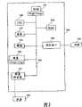
参照图1,显示了一款类似法国达索系统公司开发,IBM公司销售的名为CATIA的CAD软件的工作环境。如显示在计算机显示屏上的工作环境主要包括一个规格树2和图形区4。Referring to Fig. 1, it shows a working environment similar to the CAD software named CATIA developed by Dassault Systèmes of France and sold by IBM. The working environment as displayed on the computer screen mainly includes a
工作环境包括一个菜单栏6,一个标准工具栏8,一个对话区10,一个包含附属在现用(活动)(actif)工作区的背景工具栏12的工作台,一个可以为当前视角指向的指南针14,一个现用工作区的图标16,和一个说明工具栏或应用工具栏18。The work environment includes a
规格树2是一种当前正在实现的一个模型的结构图形表示,这里是一架飞机。在图1的例子中,可以观察到正在进行被命名为产品1的现用元素,该产品包含5个独立的主体20A“环境”,20B“飞机机身1”,20C“机翼”,20D“对称翼”和20E“尾部”,一个主体由应用程序40和命令参数30构成。
随着部件的确定,模型树的新项目更为丰富。With the identification of parts, the new items of the model tree are enriched.
一个元素的选择在图表区4或者规格树2内完成没有区别。规格树允许激活被选定对象的背景菜单。It makes no difference whether the selection of an element is done in the
规格树2每一个元素可以包括命令参数30以及关系(未显示),它们能够通过定义规格树中当前功能影响一个或多个实体的几何图。Each element of the
这样一个CAD软件的使用同样能够实现一个数字模型并以相应的方式确定产品和某些与之相关的工艺流程。The use of such a CAD software likewise makes it possible to implement a digital model and define the product and certain processes associated therewith in a corresponding manner.
最常见的是,三维几何模型的确定是数个工作组的努力,通常在不同的地点组织这些工作组,经常是跨国界的。由此产生对参数信息简单容易的交流的强烈需求。Most commonly, the determination of the 3D geometric model is the effort of several working groups, usually organized in different locations, often across borders. This creates a strong need for simple and easy communication of parameter information.
在实际中,定义参数直接由软件工具的本来的功能性决定,尤其是“CATIA”。要修改一个模型的参数值,无需重新编译应用程序。只需使用软件的标准功能来修改参数。尽管如此,软件工具以与构建历史有关的结构组织或以隶属树形式表示模型。In practice, the definition parameters are directly determined by the intrinsic functionality of the software tool, in particular "CATIA". To modify parameter values of a model, it is not necessary to recompile the application. Simply use the software's standard functions to modify parameters. Nevertheless, software tools organize the structure in relation to the construction history or represent the model in the form of affiliation tree.
然而,这种表示相对地偏离了与参数模型设计相关的技术问题的可操作方案。However, this representation deviates relatively from an operational solution to the technical problems associated with parametric model design.
于是,这对于一位非软件专业的使用者来说在只了解其希望实现的结果的情况下就能轻易地重新找出一个参数是相对困难的。Therefore, it is relatively difficult for a non-software professional user to easily find out a parameter again when he only knows the result he wishes to achieve.
发明内容Contents of the invention
本发明正是对此问题提供了一种解决方案。It is to this problem that the present invention provides a solution.
本发明旨在向非专业使用者提供一个与部件设计相关的技术问题的可操作方案中的结构参数编辑器,以便得到一个修改参数的简化界面,而不必修改源代码。The present invention aims to provide non-professional users with an editor of structural parameters in an operable solution to technical problems related to component design, in order to obtain a simplified interface for modifying parameters without having to modify the source code.
它作为一个或一套部件的三维几何模型的生成设备,所述模型以包含至少由一个命令参数确定的至少一个元素的规格树的形式图形表示在计算机屏幕上。It acts as a generating device of a three-dimensional geometric model of a component or a set of components, said model being represented graphically on a computer screen in the form of a specification tree containing at least one element determined by at least one command parameter.
根据本发明的通常定义,生成设备包含一个转换器,适于将所述规格树转换为一个用户图形界面,其中对于所述树中的至少一个现用元素关联一个对话框,所述对话框包含与所述现用元素的至少一个命令参数相对应的至少一个域,所述命令参数的调节可由用户借助一个参数编辑器进行修改,所述命令参数的每次调节显示在对话框的相应域中并自动执行规格树中对应的现用元素的命令参数的调节的修改。According to a general definition of the invention, the generation device comprises a converter adapted to convert said specification tree into a graphical user interface, wherein for at least one active element in said tree is associated a dialog box containing at least one field corresponding to at least one command parameter of said active element, the adjustment of said command parameter being modifiable by the user by means of a parameter editor, each adjustment of said command parameter being displayed in the corresponding field of the dialog box And the adjustment modification of the command parameter of the corresponding active element in the specification tree is executed automatically.
因此,利用本发明的对话框,一个用户可以轻易地直接修改现用元素的参数域的数值,而不必是一个CAD软件技术人员。而且,借助对话框的参数修改引起规格树中相应的修改。结果是,对一位非专业用户而言,对CAD软件规格树的现用元素的命令参数进行访问和修改会非常便利和简单。而且,利用本发明的参数结构的修改无需源代码的修改。Therefore, using the dialog box of the present invention, a user can easily and directly modify the value of the parameter field of the active element without being a CAD software technician. Furthermore, a parameter modification by means of a dialog box causes a corresponding modification in the specification tree. As a result, accessing and modifying the command parameters of the active elements of the specification tree of the CAD software is very convenient and simple for a non-expert user. Furthermore, modification of the parameter structure utilizing the present invention does not require modification of the source code.
根据一种实现方式,图形界面还包括一个包含相应现用元素几何特性的图形窗口,所述参数的调节直观地显示在上述图形窗口中。According to an implementation manner, the graphical interface further includes a graphical window containing geometric properties of corresponding active elements, and the adjustment of the parameters is intuitively displayed in the graphical window.
同样,通常被CAD软件专家定义且被非专业用户认为有趣的命令参数是在符合本发明的图形界面和/或对话框上直接可见且可修改的。Likewise, command parameters that are usually defined by CAD software experts and considered interesting by non-professional users are directly visible and modifiable on graphical interfaces and/or dialog boxes consistent with the present invention.
实际中,规格树的每个元素属于由终端节点和非终端节点形成的组。In practice, each element of the specification tree belongs to a group formed by terminal nodes and non-terminal nodes.
例如,在每个终端节点上关联一个用户图形窗口类的显示器和一个参数编辑器。For example, associate a user graphics window class display and a parameter editor with each terminal node.
同样的,在每个非终端节点上关联一个参数编辑器和多个选项标签(onglet),在每个选项标签上关联一个子节点。Likewise, associate a parameter editor and multiple option tags (onglets) with each non-terminal node, and associate a child node with each option tag.
例如,对至少某些选项标签关联一个图形窗口。For example, associate a graphics window with at least some option labels.
按照另一种实现方式,参数编辑器还可以是一个脚本编辑器,其中脚本语言譬如是XML型标记语言。According to another implementation, the parameter editor can also be a script editor, wherein the script language is, for example, an XML-type markup language.
按照又一种实现方式,生成设备另外包含一个可以远距离交换参数域数值的通信装置用于与其他用户进行远距离协同工作。According to yet another implementation, the generating device additionally includes a communication device capable of remotely exchanging parameter field values for remote collaborative work with other users.
本发明同样提供一个与一个部件或一套部件相关的三维几何体的参数模型生成方法,所述模型以包含由至少一个命令参数确定的至少一个元素的规格树形式图形显示在计算机屏幕上。The invention also provides a method for generating a parametric model of a three-dimensional geometry associated with a part or a set of parts, said model being graphically displayed on a computer screen in the form of a specification tree comprising at least one element determined by at least one command parameter.
按照本发明的另一个方面,方法包括下列步骤:According to another aspect of the present invention, the method comprises the steps of:
- 将所述规格树转换成一个用户图形界面,其中所述树的至少一个现用元素关联一个对话框,该对话框包含与现用元素的至少一个命令参数相关联的至少一个域。- converting said specification tree into a graphical user interface, wherein at least one active element of said tree is associated with a dialog box containing at least one field associated with at least one command parameter of the active element.
- 由用户借助参数编辑器修改命令参数的调节,- Modification of command parameters by the user with the help of the parameter editor,
- 在对话框的对应域里显示所述命令参数的每一次调节,和- display each adjustment of said command parameter in the corresponding field of the dialog, and
- 自动改变规格树中相应现用元素命令参数的调节。- Automatically change the adjustment of the command parameter corresponding to the active element in the specification tree.
按照一种实现方式,方法还包括一步骤,此步骤中所述参数的调节被直观地显示在图形窗口中。According to an implementation, the method further includes a step, in which the adjustment of the parameter is visually displayed in a graphics window.
本发明同时旨在提供一种信息系统可读信息载体,特征在于它包含信息程序指令,当这一程序被一信息系统加载且执行时,使执行针对上述目的的生成方法。The present invention also aims to provide an information carrier readable by an information system, characterized in that it contains information program instructions, which, when this program is loaded and executed by an information system, cause the generation method for the above-mentioned purpose to be performed.
本发明同时旨在提供一种可拆卸的(amovible)信息载体,可部分或全部地被信息系统读取,其特征在于它包含信息程序指令,当这一程序被一信息系统加载且执行时,使执行针对上述目的的生成方法。The present invention also aims to provide a detachable (amovible) information carrier, which can be partially or completely read by an information system, and is characterized in that it contains information program instructions. When this program is loaded and executed by an information system, Make execute generate method for above purpose.
本发明最后旨在提供存储在信息载体上的计算机程序,所述程序包含指令,当这一程序被一信息系统加载且执行时,使执行针对前述目的的生成方法。The invention finally aims to provide a computer program stored on an information carrier, said program comprising instructions, which, when this program is loaded and executed by an information system, cause the execution of the generation method for the aforementioned purposes.
附图说明Description of drawings
本发明的其他特征和优点根据下述详细描述和附图将更加明显,其中:Other features and advantages of the present invention will become apparent from the following detailed description and accompanying drawings, in which:
- 已作描述的图1以图解形式表示现有技术中CAD软件的工作环境;- Figure 1, already described, diagrammatically represents the working environment of CAD software in the prior art;
- 图2以图解形式表示可以实施本发明的计算机物理资源;- Figure 2 represents in diagrammatic form the computer physical resources that can implement the invention;
- 图3以图解形式表示图1的工作环境,其中响应用户的请求后重叠显示符合本发明的对话框;- Fig. 3 is a diagrammatic representation of the working environment of Fig. 1, in which dialog boxes according to the present invention are superimposed and displayed in response to the user's request;
- 图4以图解形式单独表示图3的对话框;- Figure 4 represents the dialog box of Figure 3 in a diagrammatic form;
- 图5通过本发明的对话框以图解形式表示参数调节(réglage)数值相对于显示在图4中的数值的变化;并且- Figure 5 graphically represents the variation of the value of the parameter adjustment (réglage) with respect to the value shown in Figure 4 by means of the dialog box of the invention; and
- 图6以图解形式表示规格树中参照图5所述参数调节相对于图1中树的变化效果。- Figure 6 graphically represents the effect of parameter adjustments in the specification tree described with reference to Figure 5 relative to the tree in Figure 1.
具体实施方式Detailed ways
参照图2,表示出用于实施本发明的可编程设备100的物理资源。Referring to FIG. 2, the physical resources of a
设备100包含一个通信总线109,在其上连接有:The
- 一个中央处理单元102(微处理器,CPU),它控制设备100的各元件之间的交换;- a central processing unit 102 (microprocessor, CPU), which controls the exchanges between the various elements of the
- 一个只读存储器(ROM)101,能够含有本发明程序(Prog1,Prog2);- a read-only memory (ROM) 101 capable of containing the programs (Prog1, Prog2) of the invention;
- 一个随机存储器(RAM)105;- a random access memory (RAM) 105;
- 一个硬盘103,能够包含前述程序;- a
- 一个键盘104;- a
- 一个屏幕107;- a
- 一个软盘阅读器111,适于接收软盘110并根据本发明读取或写入处理完毕或有待处理的文档;- a
- 连接到一个通信网络120,如因特网的一个通信接口106,接口适于发送和接收文档。- A
通信总线109使设备内或与之连接的不同元件之间的通信和协同工作成为可能。总线的表示并非限制性的,而且特别是,允许中央处理单元直接或通过设备的另一个元件作为中介传送指令给设备的任何元件。
使可编程设备能够实现根据本发明的处理的每一程序的可执行代码可被存储在例如硬盘103或只读存储器101中。The executable code of each program enabling the programmable device to realize the processing according to the present invention may be stored in the
根据一个变化的实现方式,软盘110可包含文档以及一旦被设备阅读就被存储在硬盘103的前述程序的可执行代码。According to a variant implementation, the
根据另一个变化的实现方式,程序的可执行代码可通过通信网络经由接口106被接收,以便以与前述相同的方式被存储。According to another variant implementation, the executable code of the program can be received via the communication network via the
软盘可由任何一种信息载体替代,例如,光盘(CD ROM)或存储卡。通常的做法是,一种信息存储装置,可被计算机或微处理器识别,安装或并不安装在设备中,必要时可拆卸,适用于存储一个或多个程序,该程序在执行时可以实施根据本发明的方法。The floppy disk can be replaced by any kind of information carrier, for example, compact disc (CD ROM) or memory card. In general practice, an information storage device, identifiable by a computer or microprocessor, installed or not installed in a device, and detachable if necessary, suitable for storing one or more programs which, when executed, implement according to the method of the invention.
更为通常的做法,这个或这些程序可在被执行之前被装载到设备的存储装置之一中。More generally, the program or programs may be loaded into one of the device's storage means before being executed.
中央处理单元102命令和控制根据本发明的这个或这些程序的软件代码段或指令的执行,指令被存储于硬盘103或只读存储器101中,亦或存储在前述的其他存储元件中。当通上电源,存储在非易失存储器,如硬盘103或ROM存储器101上的这个或这些程序,根据本发明被转移到只读存储器RAM上,该只读存储器RAM将含有这个或这些程序的可执行代码的,也转移到用于存储使本发明实现所必需的参数变量的寄存器中。The
应当注意根据本发明包含上述装置的可编程设备也可成为一台已被编程的设备。It should be noted that a programmable device according to the present invention comprising the means described above can also be a programmed device.
这一设备因而包含这一或这些信息程序的代码,例如被固化在专用集成电路上(ASIC)。This device thus contains the code of this or these information programs, for example embodied on an application specific integrated circuit (ASIC).
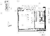
参照图3,显示了图1中航空器的三维数字模型的工作环境。我们再次看到航空器4的图形表示和规格树2。Referring to FIG. 3 , the working environment of the three-dimensional digital model of the aircraft in FIG. 1 is shown. Again we see the graphical representation of
当选择规格树2的其中一个现用元素,这里是元素“机身fuselage.1”20B,并激活位于工具栏18里的按钮或图标18A“参数编辑”时,又一个图形界面50出现在微计算机屏幕上,重叠显示在第一个图形界面4上。When selecting one of the active elements of the
这个图形界面50是一个对话框,至少包括与命令参数有关的一部分54和必要时候出现的关于相应元素的几何体的一部分52。图形界面50包含用于模型20B“机身fuselage.1”的每一个元素的选项标签60。这些标签60被个体化为60A到60F,分别对应元素“全视图”,“主体”,“横切面”,“机舱”,“汽缸”和“尾部”。This
在部分54中,可看见一个对应选中标签的命令参数清单70,这里是对应“横切面”的标签60C。In
参数70被个体化为70A到70K。每一个参数70对应一个域80,域中数值可由用户借助于数值改变装置如一个升降器82或一个游标82H进行修改。每一个参数同样包括一个选择按钮84。Parameters 70 are individualized as 70A to 70K. Each parameter 70 corresponds to a field 80 in which the value can be modified by the user by means of value changing means such as a lifter 82 or a
图标18A是一个可以根据本发明发出显示对话框50的命令的快捷方式。这一命令生成一个参数编辑器,用于在结构上和功能上反映模型而无须直接依靠规格树或部件的构造历史。参数编辑器展示用于编辑模型的某些参数至少参数70的各个域80。域80与模型参数直接关联。
图形界面50由三个按钮:确认按钮“OK”90A、应用按钮90B和取消按钮90C构成。
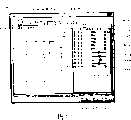
参照图4,用户在对话框50的部分54中选择他想要在对话框50的部分52中处理、修改和/或可视化的参数。这里,用户选择对应于横切面机身高度的参数70A。记录在对应域80A中的原始数值这里是3000mm。用户使受对话框中部分52中的参数70A影响的几何部分可视化。Referring to FIG. 4 , the user selects in
参照图5,用户希望根据图4中显示的数值修改参数70A的调节数值。例如这里,他借助升降器82A修改参数70A关于机身横截面的高度值(新数值=2000mm)。参数数值改变的效果在图形窗口52中被实时地(1至2秒钟)明显显示。Referring to FIG. 5 , the user wishes to modify the adjustment value of
确认按钮90A(OK)的选择使得参数新数值自动加入到产品的全部元件中。Selection of
参照图6,人们显然自动地观察到:参数70A数值借助于参考图5描述的对话框50的改变,引起规格树2和显示在图形界面4上的几何图相对于参照图1所述的工作环境2和4的相应改变(这里机身横截面缩小)。Referring to Fig. 6, one obviously automatically observes that the change of the
实际中,是一转换器将规格树2转换成一个用户图形界面50、52、54,其中至少一个现用元素,这里是图2至6中所述树2的现用元素20B,被关联一个对话框,该对话框包含至少一个与所述现用元素的至少一个命令参数70A关联的域80A。实际中,根据本发明需要转换器生成一个结构参数编辑器,它在与部件设计相关的技术问题的可操作方案中提供了可由非专业用户输入参数的域。In practice, a converter transforms the
命令参数70A的调节是可由一位CAD软件非专业用户通过选择图标18A启动根据本发明的参数编辑器修改的。实际中,参数编辑器利用CAD软件中的可用参数编辑器的自带功能。Adjustment of the
根据本发明的参数编辑器借助所述自带功能组织和结构化对话框50中的模型的参数。The parameter editor according to the invention organizes and structures the parameters of the model in the
所述命令参数的每一次调节直观地被显示在相应的域80并自动引起规格树2中相应现用元素的命令参数调节的变化。因此,一位用户可以轻易并直接地通过对话框修改参数的数值。Each adjustment of said command parameter is intuitively displayed in the corresponding field 80 and automatically causes a change in the adjustment of the command parameter of the corresponding active element in the
图形窗口52包括相应现用元素20B的几何图,所述参数的调节被显示在所述图形窗口52,它使非专业用户可直观地确认参数数值的变化效果。The
实际中,转换器根据所选择的编辑和转换规则转转每个现用元素成一个对话框。In practice, the converter converts each active element into a dialog according to the selected editing and conversion rules.
例如,规格树2中的每个元素20A,20B,20C,20D,20E属于由终端节点和非终端节点构成的组。在每一个终端节点上关联一个用户图形窗口型可视显示器52和一个参数编辑器18A。在每一个非终端节点上关联一个参数编辑器18A和多个标签60,每一个标签60关联一个子节点62。For example, each
实际中,参数编辑器还是一个脚本编辑器,例如脚本语言是一种XML型标记语言。In practice, the parameter editor is also a script editor, for example, the script language is an XML markup language.
因而,由于通信接口106,可以远距离,以XML文件形式,交换参数域80的数值。这样一种交换允许通过交换仅包含参数的修改的文本或脚本形式的小文件,来与其它用户进行远距离协同工作。Thus, thanks to the
转换器在实际中体现为被一种扩展机制附加到CAD软件的一系列补充软件功能形式,被称为“插件”。这种扩展在物理上由文本文件、图标或CAD软件文件形式的一系列动态库和资源文件组成。In practice, the converter is embodied as a series of supplementary software functions added to the CAD software by an extension mechanism, which is called "plug-in". This extension physically consists of a series of dynamic libraries and resource files in the form of text files, icons or CAD software files.
编辑规则可区分两种类别的命令参数:可修改参数和不可修改参数。Editing rules distinguish two categories of command parameters: modifiable parameters and non-modifiable parameters.
根据本发明的转换软件在打开一个已经被CAD软件如Catia V5版创建的三维模型后被启动。转换软件可轻易并直接地修改三维模型的参数而不要求CAD软件的深入了解且不会造成对源代码的修改。The conversion software according to the invention is activated after opening a three-dimensional model that has been created by CAD software such as Catia V5 edition. The conversion software can easily and directly modify the parameters of the 3D model without requiring in-depth knowledge of the CAD software and without causing modifications to the source code.
Claims (15)
Applications Claiming Priority (3)
| Application Number | Priority Date | Filing Date | Title |
|---|---|---|---|
| FR0505029 | 2005-05-19 | ||
| FR0505029AFR2886030B1 (en) | 2005-05-19 | 2005-05-19 | METHOD AND DEVICE FOR GENERATING A PARAMETRIC MODEL RELATING TO 3D GEOMETRY |
| PCT/FR2006/001075WO2006123040A2 (en) | 2005-05-19 | 2006-05-12 | Method and device for generating a parametric model linked to a 3d geometry |
Publications (2)
| Publication Number | Publication Date |
|---|---|
| CN101198957Atrue CN101198957A (en) | 2008-06-11 |
| CN101198957B CN101198957B (en) | 2012-06-06 |
Family
ID=35058136
Family Applications (1)
| Application Number | Title | Priority Date | Filing Date |
|---|---|---|---|
| CN2006800214659AExpired - Fee RelatedCN101198957B (en) | 2005-05-19 | 2006-05-12 | Method and device for generation of a parametric model associated with a 3d geometry |
Country Status (8)
| Country | Link |
|---|---|
| EP (1) | EP1889196A2 (en) |
| JP (1) | JP5009901B2 (en) |
| CN (1) | CN101198957B (en) |
| BR (1) | BRPI0612929A2 (en) |
| CA (1) | CA2608320A1 (en) |
| FR (1) | FR2886030B1 (en) |
| RU (1) | RU2474874C2 (en) |
| WO (1) | WO2006123040A2 (en) |
Cited By (4)
| Publication number | Priority date | Publication date | Assignee | Title |
|---|---|---|---|---|
| CN102804186A (en)* | 2009-06-19 | 2012-11-28 | 微软公司 | Solver-based Visualization Framework |
| CN105488240A (en)* | 2014-10-11 | 2016-04-13 | 中国航空工业集团公司西安飞机设计研究所 | Rapid generating method for three-dimensional model of integral wing rib |
| CN109343842A (en)* | 2018-10-09 | 2019-02-15 | 上海莉莉丝科技股份有限公司 | Method, system, equipment and the medium of object are shown in editing machine |
| CN112106054A (en)* | 2018-05-09 | 2020-12-18 | 西门子股份公司 | Preparation of three-dimensional models for data transmission |
Families Citing this family (9)
| Publication number | Priority date | Publication date | Assignee | Title |
|---|---|---|---|---|
| EP2266021A4 (en) | 2008-04-04 | 2014-01-01 | Landmark Graphics Corp | Systems and methods for correlating meta-data model representations and asset-logic model representations |
| US10552391B2 (en) | 2008-04-04 | 2020-02-04 | Landmark Graphics Corporation | Systems and methods for real time data management in a collaborative environment |
| JP2011221718A (en) | 2010-04-07 | 2011-11-04 | Sony Corp | Generation device, generation method, and program |
| KR101307350B1 (en) | 2012-04-24 | 2013-09-11 | 국방과학연구소 | Method and apparatus for embodying instrument panel of reconfigurable flight simulator using graphic images |
| US10061481B2 (en)* | 2013-02-28 | 2018-08-28 | The Boeing Company | Methods and devices for visually querying an aircraft based on an area of an image |
| US10437938B2 (en)* | 2015-02-25 | 2019-10-08 | Onshape Inc. | Multi-user cloud parametric feature-based 3D CAD system |
| US10423884B2 (en) | 2015-06-04 | 2019-09-24 | The Mathworks, Inc. | Extension of model-based design to identify and analyze impact of reliability information on systems and components |
| CN110930511B (en)* | 2019-07-25 | 2023-03-31 | 上海钢通网络科技有限公司 | Support arrangement design editing method in steel bridge design |
| CN112100779B (en)* | 2020-08-21 | 2024-05-14 | 广州明珞装备股份有限公司 | Method, system, device and medium for generating electrical drawing |
Family Cites Families (11)
| Publication number | Priority date | Publication date | Assignee | Title |
|---|---|---|---|---|
| JP2754540B2 (en)* | 1987-10-02 | 1998-05-20 | 松下電器産業株式会社 | Pulse counting type detector |
| US6360357B1 (en)* | 1999-06-10 | 2002-03-19 | Dassault Systems | Adding code in an application during runtime to enrich object behavior |
| US6611725B1 (en)* | 2000-02-03 | 2003-08-26 | Solidworks Corporation | Computer drawing system |
| US7079990B2 (en)* | 2001-02-08 | 2006-07-18 | Solidworks Corporation | Automated connections of computer-aided design components |
| US7176942B2 (en)* | 2001-03-23 | 2007-02-13 | Dassault Systemes | Collaborative design |
| US6768486B1 (en)* | 2001-05-18 | 2004-07-27 | Autodesk, Inc. | Modifying subobjects of geometry objects based on per-subobject objects |
| RU2324975C2 (en)* | 2001-12-21 | 2008-05-20 | Здфакто Апс | Method, computer system and software product for setting virtual representation of multiple part composition |
| EP1355485A1 (en)* | 2002-04-18 | 2003-10-22 | Deutsche Thomson-Brandt Gmbh | Method for generating a user interface on a HAVi device for the control of a Non-HAVi device |
| GB2388002B (en)* | 2002-04-26 | 2004-05-12 | Oracle Int Corp | Graphical modelling system |
| US7283939B2 (en)* | 2003-05-14 | 2007-10-16 | Incs Inc. | Method, system and program for supporting mechanism design |
| JP3939310B2 (en)* | 2003-05-14 | 2007-07-04 | 株式会社インクス | Mechanism design support method, mechanism design support system, and mechanism design support program |
- 2005
- 2005-05-19FRFR0505029Apatent/FR2886030B1/ennot_activeExpired - Fee Related
- 2006
- 2006-05-12WOPCT/FR2006/001075patent/WO2006123040A2/enactiveApplication Filing
- 2006-05-12CACA002608320Apatent/CA2608320A1/ennot_activeAbandoned
- 2006-05-12JPJP2008511747Apatent/JP5009901B2/ennot_activeExpired - Fee Related
- 2006-05-12RURU2007147335/08Apatent/RU2474874C2/ennot_activeIP Right Cessation
- 2006-05-12CNCN2006800214659Apatent/CN101198957B/ennot_activeExpired - Fee Related
- 2006-05-12EPEP06764617Apatent/EP1889196A2/ennot_activeWithdrawn
- 2006-05-12BRBRPI0612929-3Apatent/BRPI0612929A2/ennot_activeApplication Discontinuation
Cited By (6)
| Publication number | Priority date | Publication date | Assignee | Title |
|---|---|---|---|---|
| CN102804186A (en)* | 2009-06-19 | 2012-11-28 | 微软公司 | Solver-based Visualization Framework |
| CN102804186B (en)* | 2009-06-19 | 2015-08-19 | 微软技术许可有限责任公司 | Solver-based visualization framework |
| CN105488240A (en)* | 2014-10-11 | 2016-04-13 | 中国航空工业集团公司西安飞机设计研究所 | Rapid generating method for three-dimensional model of integral wing rib |
| CN112106054A (en)* | 2018-05-09 | 2020-12-18 | 西门子股份公司 | Preparation of three-dimensional models for data transmission |
| CN109343842A (en)* | 2018-10-09 | 2019-02-15 | 上海莉莉丝科技股份有限公司 | Method, system, equipment and the medium of object are shown in editing machine |
| US11294541B2 (en) | 2018-10-09 | 2022-04-05 | Shanghai Lilith Technology Corporation | Method, system, and device for displaying geometry in editor, and medium |
Also Published As
| Publication number | Publication date |
|---|---|
| WO2006123040A3 (en) | 2007-05-10 |
| FR2886030B1 (en) | 2007-08-10 |
| CN101198957B (en) | 2012-06-06 |
| CA2608320A1 (en) | 2006-11-23 |
| JP2008541286A (en) | 2008-11-20 |
| JP5009901B2 (en) | 2012-08-29 |
| RU2474874C2 (en) | 2013-02-10 |
| BRPI0612929A2 (en) | 2010-12-07 |
| RU2007147335A (en) | 2009-06-27 |
| WO2006123040A2 (en) | 2006-11-23 |
| EP1889196A2 (en) | 2008-02-20 |
| FR2886030A1 (en) | 2006-11-24 |
Similar Documents
| Publication | Publication Date | Title |
|---|---|---|
| CN101198957A (en) | Method and device for generating parametric models related to three-dimensional geometry | |
| KR101885089B1 (en) | Excel export method for bim design files | |
| US8046735B1 (en) | Transforming graphical objects in a graphical modeling environment | |
| RU2409844C2 (en) | Markup-based extensibility for user interfaces | |
| JP5049280B2 (en) | Extensible XML format and object model for localization data | |
| US20040060037A1 (en) | Method for gesture based modeling | |
| CN113886362A (en) | Data storage system and storage method based on workflow engine and low-code platform | |
| KR20060087995A (en) | Methods and systems for modeling workflow | |
| WO2006055720A1 (en) | Dynamic generation of formatted user interfaces in software environments | |
| US20070038947A1 (en) | Method and device for generation of a parametric model associated with a 3D geometry | |
| US7899846B2 (en) | Declarative model editor generation | |
| Da Silva et al. | Integration of RE and MDE paradigms: the ProjectIT approach and tools | |
| CN115495069B (en) | Model-driven coal industry software process implementation method, device and equipment | |
| CN112631585B (en) | XML-based rapid parameter interface configuration method | |
| US8074200B2 (en) | Method and system for providing tooling instructions through parameterization as an aid for software application development | |
| CN119718308A (en) | Managing apps, such as user interfaces, methods, and systems for developing apps | |
| JP2009193489A (en) | Work procedure manual creation system | |
| Puerta et al. | Interactively mapping task models to interfaces in MOBI-D | |
| CN117215556A (en) | Modularized page rapid construction method, system, equipment and medium | |
| KR101985491B1 (en) | Result generating and monitoring apparatus using visualzation of formula with diagram mode | |
| Sprogis et al. | Specification, configuration and implementation of DSL tool | |
| Tching et al. | IM-sgi: an interface model for shape grammar implementations | |
| Babris et al. | From Models to Interfaces: Leveraging the Two-Hemisphere Model for Automated UI Generation | |
| Mbang* et al. | Automation of the computer-aided design–computer-aided quality assurance process chain in car body engineering | |
| Li et al. | Research on a pattern-based user interface development method |
Legal Events
| Date | Code | Title | Description |
|---|---|---|---|
| C06 | Publication | ||
| PB01 | Publication | ||
| C10 | Entry into substantive examination | ||
| SE01 | Entry into force of request for substantive examination | ||
| C14 | Grant of patent or utility model | ||
| GR01 | Patent grant | ||
| CF01 | Termination of patent right due to non-payment of annual fee | ||
| CF01 | Termination of patent right due to non-payment of annual fee | Granted publication date:20120606 Termination date:20210512 |