CN101198298A - Expandable spinal implant and related placement procedure - Google Patents
Expandable spinal implant and related placement procedureDownload PDFInfo
- Publication number
- CN101198298A CN101198298ACNA2006800217731ACN200680021773ACN101198298ACN 101198298 ACN101198298 ACN 101198298ACN A2006800217731 ACNA2006800217731 ACN A2006800217731ACN 200680021773 ACN200680021773 ACN 200680021773ACN 101198298 ACN101198298 ACN 101198298A
- Authority
- CN
- China
- Prior art keywords
- implant
- axial wall
- wall portion
- implant body
- axial
- Prior art date
- Legal status (The legal status is an assumption and is not a legal conclusion. Google has not performed a legal analysis and makes no representation as to the accuracy of the status listed.)
- Pending
Links
Images


Classifications
- A—HUMAN NECESSITIES
- A61—MEDICAL OR VETERINARY SCIENCE; HYGIENE
- A61F—FILTERS IMPLANTABLE INTO BLOOD VESSELS; PROSTHESES; DEVICES PROVIDING PATENCY TO, OR PREVENTING COLLAPSING OF, TUBULAR STRUCTURES OF THE BODY, e.g. STENTS; ORTHOPAEDIC, NURSING OR CONTRACEPTIVE DEVICES; FOMENTATION; TREATMENT OR PROTECTION OF EYES OR EARS; BANDAGES, DRESSINGS OR ABSORBENT PADS; FIRST-AID KITS
- A61F2/00—Filters implantable into blood vessels; Prostheses, i.e. artificial substitutes or replacements for parts of the body; Appliances for connecting them with the body; Devices providing patency to, or preventing collapsing of, tubular structures of the body, e.g. stents
- A61F2/02—Prostheses implantable into the body
- A61F2/30—Joints
- A61F2/44—Joints for the spine, e.g. vertebrae, spinal discs
- A61F2/4455—Joints for the spine, e.g. vertebrae, spinal discs for the fusion of spinal bodies, e.g. intervertebral fusion of adjacent spinal bodies, e.g. fusion cages
- A61F2/447—Joints for the spine, e.g. vertebrae, spinal discs for the fusion of spinal bodies, e.g. intervertebral fusion of adjacent spinal bodies, e.g. fusion cages substantially parallelepipedal, e.g. having a rectangular or trapezoidal cross-section
- A—HUMAN NECESSITIES
- A61—MEDICAL OR VETERINARY SCIENCE; HYGIENE
- A61F—FILTERS IMPLANTABLE INTO BLOOD VESSELS; PROSTHESES; DEVICES PROVIDING PATENCY TO, OR PREVENTING COLLAPSING OF, TUBULAR STRUCTURES OF THE BODY, e.g. STENTS; ORTHOPAEDIC, NURSING OR CONTRACEPTIVE DEVICES; FOMENTATION; TREATMENT OR PROTECTION OF EYES OR EARS; BANDAGES, DRESSINGS OR ABSORBENT PADS; FIRST-AID KITS
- A61F2/00—Filters implantable into blood vessels; Prostheses, i.e. artificial substitutes or replacements for parts of the body; Appliances for connecting them with the body; Devices providing patency to, or preventing collapsing of, tubular structures of the body, e.g. stents
- A61F2/02—Prostheses implantable into the body
- A61F2/30—Joints
- A61F2/46—Special tools for implanting artificial joints
- A61F2/4603—Special tools for implanting artificial joints for insertion or extraction of endoprosthetic joints or of accessories thereof
- A61F2/4611—Special tools for implanting artificial joints for insertion or extraction of endoprosthetic joints or of accessories thereof of spinal prostheses
- A—HUMAN NECESSITIES
- A61—MEDICAL OR VETERINARY SCIENCE; HYGIENE
- A61F—FILTERS IMPLANTABLE INTO BLOOD VESSELS; PROSTHESES; DEVICES PROVIDING PATENCY TO, OR PREVENTING COLLAPSING OF, TUBULAR STRUCTURES OF THE BODY, e.g. STENTS; ORTHOPAEDIC, NURSING OR CONTRACEPTIVE DEVICES; FOMENTATION; TREATMENT OR PROTECTION OF EYES OR EARS; BANDAGES, DRESSINGS OR ABSORBENT PADS; FIRST-AID KITS
- A61F2/00—Filters implantable into blood vessels; Prostheses, i.e. artificial substitutes or replacements for parts of the body; Appliances for connecting them with the body; Devices providing patency to, or preventing collapsing of, tubular structures of the body, e.g. stents
- A61F2/02—Prostheses implantable into the body
- A61F2/28—Bones
- A61F2002/2817—Bone stimulation by chemical reactions or by osteogenic or biological products for enhancing ossification, e.g. by bone morphogenetic or morphogenic proteins [BMP] or by transforming growth factors [TGF]
- A—HUMAN NECESSITIES
- A61—MEDICAL OR VETERINARY SCIENCE; HYGIENE
- A61F—FILTERS IMPLANTABLE INTO BLOOD VESSELS; PROSTHESES; DEVICES PROVIDING PATENCY TO, OR PREVENTING COLLAPSING OF, TUBULAR STRUCTURES OF THE BODY, e.g. STENTS; ORTHOPAEDIC, NURSING OR CONTRACEPTIVE DEVICES; FOMENTATION; TREATMENT OR PROTECTION OF EYES OR EARS; BANDAGES, DRESSINGS OR ABSORBENT PADS; FIRST-AID KITS
- A61F2/00—Filters implantable into blood vessels; Prostheses, i.e. artificial substitutes or replacements for parts of the body; Appliances for connecting them with the body; Devices providing patency to, or preventing collapsing of, tubular structures of the body, e.g. stents
- A61F2/02—Prostheses implantable into the body
- A61F2/28—Bones
- A61F2002/2835—Bone graft implants for filling a bony defect or an endoprosthesis cavity, e.g. by synthetic material or biological material
- A—HUMAN NECESSITIES
- A61—MEDICAL OR VETERINARY SCIENCE; HYGIENE
- A61F—FILTERS IMPLANTABLE INTO BLOOD VESSELS; PROSTHESES; DEVICES PROVIDING PATENCY TO, OR PREVENTING COLLAPSING OF, TUBULAR STRUCTURES OF THE BODY, e.g. STENTS; ORTHOPAEDIC, NURSING OR CONTRACEPTIVE DEVICES; FOMENTATION; TREATMENT OR PROTECTION OF EYES OR EARS; BANDAGES, DRESSINGS OR ABSORBENT PADS; FIRST-AID KITS
- A61F2/00—Filters implantable into blood vessels; Prostheses, i.e. artificial substitutes or replacements for parts of the body; Appliances for connecting them with the body; Devices providing patency to, or preventing collapsing of, tubular structures of the body, e.g. stents
- A61F2/02—Prostheses implantable into the body
- A61F2/30—Joints
- A61F2002/30001—Additional features of subject-matter classified in A61F2/28, A61F2/30 and subgroups thereof
- A61F2002/30316—The prosthesis having different structural features at different locations within the same prosthesis; Connections between prosthetic parts; Special structural features of bone or joint prostheses not otherwise provided for
- A61F2002/30535—Special structural features of bone or joint prostheses not otherwise provided for
- A61F2002/30579—Special structural features of bone or joint prostheses not otherwise provided for with mechanically expandable devices, e.g. fixation devices
- A—HUMAN NECESSITIES
- A61—MEDICAL OR VETERINARY SCIENCE; HYGIENE
- A61F—FILTERS IMPLANTABLE INTO BLOOD VESSELS; PROSTHESES; DEVICES PROVIDING PATENCY TO, OR PREVENTING COLLAPSING OF, TUBULAR STRUCTURES OF THE BODY, e.g. STENTS; ORTHOPAEDIC, NURSING OR CONTRACEPTIVE DEVICES; FOMENTATION; TREATMENT OR PROTECTION OF EYES OR EARS; BANDAGES, DRESSINGS OR ABSORBENT PADS; FIRST-AID KITS
- A61F2/00—Filters implantable into blood vessels; Prostheses, i.e. artificial substitutes or replacements for parts of the body; Appliances for connecting them with the body; Devices providing patency to, or preventing collapsing of, tubular structures of the body, e.g. stents
- A61F2/02—Prostheses implantable into the body
- A61F2/30—Joints
- A61F2002/30001—Additional features of subject-matter classified in A61F2/28, A61F2/30 and subgroups thereof
- A61F2002/30316—The prosthesis having different structural features at different locations within the same prosthesis; Connections between prosthetic parts; Special structural features of bone or joint prostheses not otherwise provided for
- A61F2002/30535—Special structural features of bone or joint prostheses not otherwise provided for
- A61F2002/30593—Special structural features of bone or joint prostheses not otherwise provided for hollow
- A—HUMAN NECESSITIES
- A61—MEDICAL OR VETERINARY SCIENCE; HYGIENE
- A61F—FILTERS IMPLANTABLE INTO BLOOD VESSELS; PROSTHESES; DEVICES PROVIDING PATENCY TO, OR PREVENTING COLLAPSING OF, TUBULAR STRUCTURES OF THE BODY, e.g. STENTS; ORTHOPAEDIC, NURSING OR CONTRACEPTIVE DEVICES; FOMENTATION; TREATMENT OR PROTECTION OF EYES OR EARS; BANDAGES, DRESSINGS OR ABSORBENT PADS; FIRST-AID KITS
- A61F2/00—Filters implantable into blood vessels; Prostheses, i.e. artificial substitutes or replacements for parts of the body; Appliances for connecting them with the body; Devices providing patency to, or preventing collapsing of, tubular structures of the body, e.g. stents
- A61F2/02—Prostheses implantable into the body
- A61F2/30—Joints
- A61F2/30767—Special external or bone-contacting surface, e.g. coating for improving bone ingrowth
- A61F2/30771—Special external or bone-contacting surface, e.g. coating for improving bone ingrowth applied in original prostheses, e.g. holes or grooves
- A61F2002/30772—Apertures or holes, e.g. of circular cross section
- A61F2002/30777—Oblong apertures
- A—HUMAN NECESSITIES
- A61—MEDICAL OR VETERINARY SCIENCE; HYGIENE
- A61F—FILTERS IMPLANTABLE INTO BLOOD VESSELS; PROSTHESES; DEVICES PROVIDING PATENCY TO, OR PREVENTING COLLAPSING OF, TUBULAR STRUCTURES OF THE BODY, e.g. STENTS; ORTHOPAEDIC, NURSING OR CONTRACEPTIVE DEVICES; FOMENTATION; TREATMENT OR PROTECTION OF EYES OR EARS; BANDAGES, DRESSINGS OR ABSORBENT PADS; FIRST-AID KITS
- A61F2/00—Filters implantable into blood vessels; Prostheses, i.e. artificial substitutes or replacements for parts of the body; Appliances for connecting them with the body; Devices providing patency to, or preventing collapsing of, tubular structures of the body, e.g. stents
- A61F2/02—Prostheses implantable into the body
- A61F2/30—Joints
- A61F2/30767—Special external or bone-contacting surface, e.g. coating for improving bone ingrowth
- A61F2/30771—Special external or bone-contacting surface, e.g. coating for improving bone ingrowth applied in original prostheses, e.g. holes or grooves
- A61F2002/3082—Grooves
- A61F2002/30827—Plurality of grooves
- A61F2002/30828—Plurality of grooves parallel
- A—HUMAN NECESSITIES
- A61—MEDICAL OR VETERINARY SCIENCE; HYGIENE
- A61F—FILTERS IMPLANTABLE INTO BLOOD VESSELS; PROSTHESES; DEVICES PROVIDING PATENCY TO, OR PREVENTING COLLAPSING OF, TUBULAR STRUCTURES OF THE BODY, e.g. STENTS; ORTHOPAEDIC, NURSING OR CONTRACEPTIVE DEVICES; FOMENTATION; TREATMENT OR PROTECTION OF EYES OR EARS; BANDAGES, DRESSINGS OR ABSORBENT PADS; FIRST-AID KITS
- A61F2/00—Filters implantable into blood vessels; Prostheses, i.e. artificial substitutes or replacements for parts of the body; Appliances for connecting them with the body; Devices providing patency to, or preventing collapsing of, tubular structures of the body, e.g. stents
- A61F2/02—Prostheses implantable into the body
- A61F2/30—Joints
- A61F2/30767—Special external or bone-contacting surface, e.g. coating for improving bone ingrowth
- A61F2/30771—Special external or bone-contacting surface, e.g. coating for improving bone ingrowth applied in original prostheses, e.g. holes or grooves
- A61F2002/30841—Sharp anchoring protrusions for impaction into the bone, e.g. sharp pins, spikes
- A—HUMAN NECESSITIES
- A61—MEDICAL OR VETERINARY SCIENCE; HYGIENE
- A61F—FILTERS IMPLANTABLE INTO BLOOD VESSELS; PROSTHESES; DEVICES PROVIDING PATENCY TO, OR PREVENTING COLLAPSING OF, TUBULAR STRUCTURES OF THE BODY, e.g. STENTS; ORTHOPAEDIC, NURSING OR CONTRACEPTIVE DEVICES; FOMENTATION; TREATMENT OR PROTECTION OF EYES OR EARS; BANDAGES, DRESSINGS OR ABSORBENT PADS; FIRST-AID KITS
- A61F2/00—Filters implantable into blood vessels; Prostheses, i.e. artificial substitutes or replacements for parts of the body; Appliances for connecting them with the body; Devices providing patency to, or preventing collapsing of, tubular structures of the body, e.g. stents
- A61F2/02—Prostheses implantable into the body
- A61F2/30—Joints
- A61F2/30767—Special external or bone-contacting surface, e.g. coating for improving bone ingrowth
- A61F2/30771—Special external or bone-contacting surface, e.g. coating for improving bone ingrowth applied in original prostheses, e.g. holes or grooves
- A61F2002/30878—Special external or bone-contacting surface, e.g. coating for improving bone ingrowth applied in original prostheses, e.g. holes or grooves with non-sharp protrusions, for instance contacting the bone for anchoring, e.g. keels, pegs, pins, posts, shanks, stems, struts
- A61F2002/30891—Plurality of protrusions
- A61F2002/30892—Plurality of protrusions parallel
- A—HUMAN NECESSITIES
- A61—MEDICAL OR VETERINARY SCIENCE; HYGIENE
- A61F—FILTERS IMPLANTABLE INTO BLOOD VESSELS; PROSTHESES; DEVICES PROVIDING PATENCY TO, OR PREVENTING COLLAPSING OF, TUBULAR STRUCTURES OF THE BODY, e.g. STENTS; ORTHOPAEDIC, NURSING OR CONTRACEPTIVE DEVICES; FOMENTATION; TREATMENT OR PROTECTION OF EYES OR EARS; BANDAGES, DRESSINGS OR ABSORBENT PADS; FIRST-AID KITS
- A61F2/00—Filters implantable into blood vessels; Prostheses, i.e. artificial substitutes or replacements for parts of the body; Appliances for connecting them with the body; Devices providing patency to, or preventing collapsing of, tubular structures of the body, e.g. stents
- A61F2/02—Prostheses implantable into the body
- A61F2/30—Joints
- A61F2/44—Joints for the spine, e.g. vertebrae, spinal discs
- A61F2002/448—Joints for the spine, e.g. vertebrae, spinal discs comprising multiple adjacent spinal implants within the same intervertebral space or within the same vertebra, e.g. comprising two adjacent spinal implants
- A—HUMAN NECESSITIES
- A61—MEDICAL OR VETERINARY SCIENCE; HYGIENE
- A61F—FILTERS IMPLANTABLE INTO BLOOD VESSELS; PROSTHESES; DEVICES PROVIDING PATENCY TO, OR PREVENTING COLLAPSING OF, TUBULAR STRUCTURES OF THE BODY, e.g. STENTS; ORTHOPAEDIC, NURSING OR CONTRACEPTIVE DEVICES; FOMENTATION; TREATMENT OR PROTECTION OF EYES OR EARS; BANDAGES, DRESSINGS OR ABSORBENT PADS; FIRST-AID KITS
- A61F2/00—Filters implantable into blood vessels; Prostheses, i.e. artificial substitutes or replacements for parts of the body; Appliances for connecting them with the body; Devices providing patency to, or preventing collapsing of, tubular structures of the body, e.g. stents
- A61F2/02—Prostheses implantable into the body
- A61F2/30—Joints
- A61F2/46—Special tools for implanting artificial joints
- A61F2/4603—Special tools for implanting artificial joints for insertion or extraction of endoprosthetic joints or of accessories thereof
- A61F2002/4625—Special tools for implanting artificial joints for insertion or extraction of endoprosthetic joints or of accessories thereof with relative movement between parts of the instrument during use
- A61F2002/4627—Special tools for implanting artificial joints for insertion or extraction of endoprosthetic joints or of accessories thereof with relative movement between parts of the instrument during use with linear motion along or rotating motion about the instrument axis or the implantation direction, e.g. telescopic, along a guiding rod, screwing inside the instrument
- A—HUMAN NECESSITIES
- A61—MEDICAL OR VETERINARY SCIENCE; HYGIENE
- A61F—FILTERS IMPLANTABLE INTO BLOOD VESSELS; PROSTHESES; DEVICES PROVIDING PATENCY TO, OR PREVENTING COLLAPSING OF, TUBULAR STRUCTURES OF THE BODY, e.g. STENTS; ORTHOPAEDIC, NURSING OR CONTRACEPTIVE DEVICES; FOMENTATION; TREATMENT OR PROTECTION OF EYES OR EARS; BANDAGES, DRESSINGS OR ABSORBENT PADS; FIRST-AID KITS
- A61F2/00—Filters implantable into blood vessels; Prostheses, i.e. artificial substitutes or replacements for parts of the body; Appliances for connecting them with the body; Devices providing patency to, or preventing collapsing of, tubular structures of the body, e.g. stents
- A61F2/02—Prostheses implantable into the body
- A61F2/30—Joints
- A61F2/46—Special tools for implanting artificial joints
- A61F2/4603—Special tools for implanting artificial joints for insertion or extraction of endoprosthetic joints or of accessories thereof
- A61F2002/4629—Special tools for implanting artificial joints for insertion or extraction of endoprosthetic joints or of accessories thereof connected to the endoprosthesis or implant via a threaded connection
- A—HUMAN NECESSITIES
- A61—MEDICAL OR VETERINARY SCIENCE; HYGIENE
- A61F—FILTERS IMPLANTABLE INTO BLOOD VESSELS; PROSTHESES; DEVICES PROVIDING PATENCY TO, OR PREVENTING COLLAPSING OF, TUBULAR STRUCTURES OF THE BODY, e.g. STENTS; ORTHOPAEDIC, NURSING OR CONTRACEPTIVE DEVICES; FOMENTATION; TREATMENT OR PROTECTION OF EYES OR EARS; BANDAGES, DRESSINGS OR ABSORBENT PADS; FIRST-AID KITS
- A61F2310/00—Prostheses classified in A61F2/28 or A61F2/30 - A61F2/44 being constructed from or coated with a particular material
- A61F2310/00005—The prosthesis being constructed from a particular material
- A61F2310/00011—Metals or alloys
- A61F2310/00017—Iron- or Fe-based alloys, e.g. stainless steel
- A—HUMAN NECESSITIES
- A61—MEDICAL OR VETERINARY SCIENCE; HYGIENE
- A61F—FILTERS IMPLANTABLE INTO BLOOD VESSELS; PROSTHESES; DEVICES PROVIDING PATENCY TO, OR PREVENTING COLLAPSING OF, TUBULAR STRUCTURES OF THE BODY, e.g. STENTS; ORTHOPAEDIC, NURSING OR CONTRACEPTIVE DEVICES; FOMENTATION; TREATMENT OR PROTECTION OF EYES OR EARS; BANDAGES, DRESSINGS OR ABSORBENT PADS; FIRST-AID KITS
- A61F2310/00—Prostheses classified in A61F2/28 or A61F2/30 - A61F2/44 being constructed from or coated with a particular material
- A61F2310/00005—The prosthesis being constructed from a particular material
- A61F2310/00011—Metals or alloys
- A61F2310/00023—Titanium or titanium-based alloys, e.g. Ti-Ni alloys
- A—HUMAN NECESSITIES
- A61—MEDICAL OR VETERINARY SCIENCE; HYGIENE
- A61F—FILTERS IMPLANTABLE INTO BLOOD VESSELS; PROSTHESES; DEVICES PROVIDING PATENCY TO, OR PREVENTING COLLAPSING OF, TUBULAR STRUCTURES OF THE BODY, e.g. STENTS; ORTHOPAEDIC, NURSING OR CONTRACEPTIVE DEVICES; FOMENTATION; TREATMENT OR PROTECTION OF EYES OR EARS; BANDAGES, DRESSINGS OR ABSORBENT PADS; FIRST-AID KITS
- A61F2310/00—Prostheses classified in A61F2/28 or A61F2/30 - A61F2/44 being constructed from or coated with a particular material
- A61F2310/00005—The prosthesis being constructed from a particular material
- A61F2310/00011—Metals or alloys
- A61F2310/00029—Cobalt-based alloys, e.g. Co-Cr alloys or Vitallium
- A—HUMAN NECESSITIES
- A61—MEDICAL OR VETERINARY SCIENCE; HYGIENE
- A61F—FILTERS IMPLANTABLE INTO BLOOD VESSELS; PROSTHESES; DEVICES PROVIDING PATENCY TO, OR PREVENTING COLLAPSING OF, TUBULAR STRUCTURES OF THE BODY, e.g. STENTS; ORTHOPAEDIC, NURSING OR CONTRACEPTIVE DEVICES; FOMENTATION; TREATMENT OR PROTECTION OF EYES OR EARS; BANDAGES, DRESSINGS OR ABSORBENT PADS; FIRST-AID KITS
- A61F2310/00—Prostheses classified in A61F2/28 or A61F2/30 - A61F2/44 being constructed from or coated with a particular material
- A61F2310/00005—The prosthesis being constructed from a particular material
- A61F2310/00179—Ceramics or ceramic-like structures
Landscapes
- Health & Medical Sciences (AREA)
- Engineering & Computer Science (AREA)
- Biomedical Technology (AREA)
- Orthopedic Medicine & Surgery (AREA)
- Transplantation (AREA)
- Neurology (AREA)
- Heart & Thoracic Surgery (AREA)
- Oral & Maxillofacial Surgery (AREA)
- Cardiology (AREA)
- Vascular Medicine (AREA)
- Life Sciences & Earth Sciences (AREA)
- Animal Behavior & Ethology (AREA)
- General Health & Medical Sciences (AREA)
- Public Health (AREA)
- Veterinary Medicine (AREA)
- Physical Education & Sports Medicine (AREA)
- Prostheses (AREA)
Abstract
Description
Translated fromChinese技术领域technical field
本发明一般涉及脊柱植入物领域,更具体地涉及可扩张脊柱植入物及相关安置过程(instrumentation)。The present invention relates generally to the field of spinal implants, and more particularly to expandable spinal implants and related instrumentation.
背景技术Background technique
已进行了许多尝试来开发一种椎间植入物,代替受损或变性的天然脊椎盘并维持相邻椎骨间足够的椎间盘间隙稳定性,至少维持到完成关节融合。椎间植入物可以是实心的,有时称为间隔物或骨栓,或者可以设计成中空内部以允许骨向内生长,有时称为融合装置或融合架。融合装置的内部可填充有骨生长诱导性物质以促进骨生长进入并通过装置,实现更快速和稳定的关节融合。Many attempts have been made to develop an intervertebral implant that replaces the damaged or degenerated natural disc and maintains adequate disc space stability between adjacent vertebrae, at least until joint fusion is complete. Intervertebral implants can be solid, sometimes called a spacer or bone plug, or can be designed with a hollow interior to allow bone ingrowth, sometimes called a fusion device or fusion frame. The interior of the fusion device can be filled with bone growth inducing substances to promote bone growth into and through the device, resulting in more rapid and stable joint fusion.
本领域已知多种类型、形状和构型的脊柱植入物。例如,较常见的设计之一是圆柱形脊柱植入物,它具有外螺纹以便插入盘间隙。因此,需要在相邻椎体中铰孔和开孔以形成用于接纳螺纹植入物的螺纹通道。然而,这些技术通常涉及相邻椎体后部铰孔过度,而使承重椎骨被切除过度,导致待处理脊柱部分不稳定。其它类型的椎间植入物一般为矩形,具有平的上下外表面,用于啮合相邻椎体。然而,平的上下外表面可能不能充分配合椎骨终板的形状,从而导致植入物与相邻椎体间的啮合不统一不一致。Various types, shapes and configurations of spinal implants are known in the art. For example, one of the more common designs is a cylindrical spinal implant that has external threads for insertion into the disc space. Accordingly, it is necessary to ream and open holes in adjacent vertebral bodies to form threaded channels for receiving threaded implants. However, these techniques usually involve over-reaming of the adjacent vertebral bodies posteriorly so that the load-bearing vertebrae are over-resected, resulting in instability of the segment of the spine being treated. Other types of intervertebral implants are generally rectangular in shape with flat upper and lower outer surfaces for engaging adjacent vertebral bodies. However, the flat upper and lower outer surfaces may not adequately conform to the shape of the vertebral endplates, resulting in inconsistent engagement of the implant with adjacent vertebral bodies.
此外,大多数椎间植入物设计是预先确定的固定高度,近似盘间隙的天然高度。插入固定高度的椎间植入物通常需要将盘间隙撑开到稍大于盘间隙天然高度的插入高度。也尝试开发多种类型的可扩张椎间植入物,其构型可沿盘间隙的高度扩张。这种类型的可扩张植入物通常包括多个臂或分支,其近端部分从固定底板延伸,远端部分保持未连接和游离以相互独立运动。一楔件在臂间位移以分开或张开臂的远端部分,使植入物转化为扩张构型,形成锥形且邻近植入物远端处为最大植入物高度。注意,楔件在相邻的臂远端部分间的定位不能提供沿植入物中部的支持以抵抗相邻椎体施加在植入物上的压力。此外,扩张楔件可占据植入物大部分的内腔,因而降低植入物中接纳骨生长诱导性物质的能力。Furthermore, most intervertebral implant designs are of a predetermined fixed height, approximating the natural height of the disc space. Insertion of a fixed height intervertebral implant typically requires distraction of the disc space to an insertion height slightly greater than the natural height of the disc space. Attempts have also been made to develop various types of expandable intervertebral implants configured to expand along the height of the disc space. Expandable implants of this type typically comprise a plurality of arms or branches, the proximal portions of which extend from a fixed base plate and the distal portions remain unattached and free for independent movement relative to each other. A wedge is displaced between the arms to separate or splay the distal end portions of the arms to convert the implant into an expanded configuration, tapered and having a maximum implant height adjacent the distal end of the implant. Note that the positioning of the wedges between adjacent distal end portions of the arms does not provide support along the middle of the implant against pressure exerted on the implant by adjacent vertebral bodies. In addition, the expansion wedge can occupy a substantial portion of the lumen of the implant, thereby reducing the ability of the implant to accommodate bone growth inducing substances.
而且,一些椎间植入物设计包括分别啮合上下椎骨终板的上下承重面以维持选定的盘间隙高度。这些植入物有时包括从上下承重面延伸的齿或其它类型的表面凸起,以助于啮合相邻椎骨终板而基本上防止植入物的移位和可能的植入物从盘间隙的脱出。然而,齿或其它类型表面凸起的加入可增加植入物的总体高度。结果,必须将相邻椎骨撑开到至少和植入物总体高度(包括齿的高度)一样大的盘间隙高度。撑开相邻椎骨以接纳植入物的总体高度可能导致盘间隙过度分离。此外,将植入物插入盘间隙还可能受到在上下承重面上延伸的齿或其它类型表面凸起的阻碍。Furthermore, some intervertebral implant designs include engaging the upper and lower load-bearing surfaces of the upper and lower vertebral endplates, respectively, to maintain a selected disc space height. These implants sometimes include teeth or other types of surface protrusions extending from the upper and lower weight-bearing surfaces to help engage adjacent vertebral endplates while substantially preventing displacement of the implant and possible displacement of the implant from the disc space. come out. However, the addition of teeth or other types of surface protrusions can increase the overall height of the implant. As a result, adjacent vertebrae must be distracted to a disc space height at least as great as the overall height of the implant, including the height of the teeth. Distraction of adjacent vertebrae to accommodate the overall height of the implant may result in excessive disc space separation. In addition, insertion of the implant into the disc space may be hindered by teeth or other types of surface protrusions extending on the upper and lower bearing surfaces.
因此,行业中一般需要提供一种改进的可扩张脊柱植入物及相关安置过程。本发明满足了这种需要并以新颖和非显而易见的方式提供了其它益处和优点。Accordingly, there is a general need in the industry to provide an improved expandable spinal implant and related placement process. The present invention fulfills this need and provides other benefits and advantages in a novel and nonobvious manner.
发明内容Contents of the invention
本发明一般涉及一种可扩张脊柱植入物及相关安置过程。虽然仅能参考所附权利要求书确定本文所覆盖的本发明的实际性质,但以本文所述优选实施方式为特征的本发明的某些形式简要描述如下。The present invention generally relates to an expandable spinal implant and related deployment procedures. While the actual nature of the invention covered herein can only be determined with reference to the appended claims, certain forms of the invention featuring preferred embodiments described herein are briefly described below.
在本发明的一种形式中,提供了一种可扩张脊柱植入物,其包括具有纵轴线并且可在初始构型和扩张构型间转变的植入体主体,所述植入物主体包括沿横轴线间隔开的第一和第二轴向壁,所述轴向壁中至少一个具有相互间侧向偏离的第一和第二轴向壁部分。植入物还包括与所述第一壁部分协同起效的扩张元件,使第一壁部分相对于第二壁部分大致沿横轴线位移而使所述植入物主体从初始构型转变至扩张构型。In one form of the invention there is provided an expandable spinal implant comprising an implant body having a longitudinal axis and transitionable between an initial configuration and an expanded configuration, the implant body comprising First and second axial walls spaced apart along the transverse axis, at least one of the axial walls having first and second axial wall portions laterally offset from each other. The implant also includes an expansion element cooperating with the first wall portion to displace the first wall portion relative to the second wall portion generally along the transverse axis to transition the implant body from an initial configuration to an expanded configuration. structure.
在本发明的另一种形式中,提供了一种可扩张脊柱植入物,其包括具有纵轴线并且可在初始构型和扩张构型间转变的植入体主体,所述植入物主体包括沿横轴线间隔开的第一和第二轴向壁,所述轴向壁中至少一个具有相互间侧向偏离的第一和第二轴向壁部分。当植入物主体处于初始构型时,第一壁部分相对于第二壁部分形成凹陷区域。植入物还包括与所述第一壁部分协同起效的扩张元件,以使所述植入物主体从初始构型转变至扩张构型,其中,凹陷部分大致沿横轴线向外扩张。In another form of the invention there is provided an expandable spinal implant comprising an implant body having a longitudinal axis and transitionable between an initial configuration and an expanded configuration, the implant body First and second axial walls spaced apart along the transverse axis are included, at least one of the axial walls having first and second axial wall portions laterally offset from each other. The first wall portion forms a recessed region relative to the second wall portion when the implant body is in the initial configuration. The implant also includes an expansion element cooperating with the first wall portion to transition the implant body from an initial configuration to an expanded configuration in which the recessed portion expands outward generally along the transverse axis.
在本发明的一种形式中,提供了一种可扩张脊柱植入物,其包括具有纵轴线并且可在初始构型和扩张构型间转变的植入体主体,所述植入物主体包括沿横轴线间隔开的第一和第二轴向壁,所述轴向壁中至少一个具有相互间侧向偏离的活动壁部分和基本固定壁部分。植入物还包括与所述活动壁部分协同起效的扩张元件,使活动壁部分相对于固定壁部分大致沿横轴线向外位移而使所述植入物主体从初始构型转变至扩张构型。In one form of the invention there is provided an expandable spinal implant comprising an implant body having a longitudinal axis and transitionable between an initial configuration and an expanded configuration, the implant body comprising First and second axial walls spaced apart along the transverse axis, at least one of said axial walls having a movable wall portion and a substantially fixed wall portion laterally offset from each other. The implant also includes an expansion element cooperating with the movable wall portion to displace the movable wall portion outwardly generally along a transverse axis relative to the fixed wall portion to transition the implant body from an initial configuration to an expanded configuration. type.
本发明的目的之一是提供一种改良的可扩张脊柱植入物及相关安置过程。通过附图和本说明书,本发明的其它目的、特征、优点、益处和方面将显而易见。It is an object of the present invention to provide an improved expandable spinal implant and associated placement procedure. Other objects, features, advantages, benefits and aspects of the invention will be apparent from the accompanying drawings and this specification.
附图说明Description of drawings
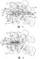
图1是根据本发明一种形式的可扩张脊柱植入物的立体图。Figure 1 is a perspective view of an expandable spinal implant in accordance with one form of the present invention.
图2是与图1所示可扩张脊柱植入物结合使用的根据本发明一个实施方式的可扩张植入物主体的侧视图。Figure 2 is a side view of an expandable implant body according to one embodiment of the present invention for use with the expandable spinal implant shown in Figure 1 .
图3是图2所示可扩张植入物主体的俯视平面图。3 is a top plan view of the expandable implant body shown in FIG. 2 .
图4是图2所示可扩张植入物主体的端视图。Figure 4 is an end view of the body of the expandable implant shown in Figure 2 .
图5是与图1所示可扩张脊柱植入物结合使用的根据本发明一个实施方式的扩张元件的端视图。5 is an end view of an expansion member according to one embodiment of the present invention used in conjunction with the expandable spinal implant shown in FIG. 1 .
图6是图5所示扩张元件的侧视图。FIG. 6 is a side view of the expansion member shown in FIG. 5 .
图7是在椎间盘间隙内处于初始非扩张状态的图1所示可扩张脊柱植入物的侧视图。7 is a side view of the expandable spinal implant of FIG. 1 in an initial, non-expanded state within the intervertebral disc space.
图8是在椎间盘间隙内处于完全扩张状态的图1所示可扩张脊柱植入物的侧视图。Figure 8 is a side view of the expandable spinal implant of Figure 1 in a fully expanded state within the intervertebral disc space.
图9是在椎间盘间隙内处于完全扩张状态的一对图1所示可扩张脊柱植入物的俯视平面图。9 is a top plan view of a pair of expandable spinal implants of FIG. 1 in a fully expanded state within an intervertebral disc space.
图10是处于初始非扩张状态的本发明另一种形式的可扩张脊柱植入物的侧视图。Figure 10 is a side view of another form of expandable spinal implant of the present invention in an initial, non-expanded state.
图11是处于初始非扩张状态的图10所示可扩张脊柱植入物的端视图。Fig. 11 is an end view of the expandable spinal implant shown in Fig. 10 in an initial, non-expanded state.
图12是处于完全扩张状态的图10所示可扩张脊柱植入物的侧视图。Figure 12 is a side view of the expandable spinal implant of Figure 10 in a fully expanded state.
图13是处于完全扩张状态的图10所示可扩张脊柱植入物的端视图。Figure 13 is an end view of the expandable spinal implant of Figure 10 in a fully expanded state.
图14是在椎间盘间隙内处于完全扩张状态的图1 0所示可扩张脊柱植入物的侧视图。Figure 14 is a side view of the expandable spinal implant shown in Figure 10 in a fully expanded state within the intervertebral disc space.
具体实施方式Detailed ways
为了促进对本发明原理的理解,现在将参考附图所示实施方式并使用具体语言来描述这些实施方式。但是,应理解,这里并不限制本发明的范围,并且认为包括所示装置的变化和进一步改进,以及本文所述本发明原理的进一步应用,如本发明所属领域技术人员通常所理解的那样。In order to promote an understanding of the principles of the invention, reference will now be made to the embodiments illustrated in the drawings and specific language will be used to describe the same. It should be understood, however, that no limitation of the scope of the invention is intended herein and is contemplated to include variations and further modifications of the illustrated apparatus, as well as further applications of the principles of the invention described herein, as commonly understood by those skilled in the art to which this invention pertains.
参考图1,显示了根据本发明一种形式的可扩张椎间植入物20。椎间植入物20沿纵轴线L延伸,大致包括可扩张植入物主体22和扩张元件24。如下文更详细所述,扩张元件24用于使植入物主体22从初始非扩张状态(如图7所示)转变为扩张状态(如图8所示),其中,植入物主体22的扩张大致沿横轴线T进行。扩张元件24也允许植入物主体22从扩张状态回缩到初始非状态状态。关于可扩张脊柱植入物20的特征及其操作的进一步描述参见下文。Referring to Figure 1, there is shown an expandable
可扩张脊柱植入物20中各个元件由生物相容性材料构成。在本发明的一个实施方式中,椎间植入物20中各个元件由金属材料构成,例如不锈钢和不锈钢合金、钛和钛合金、形状记忆合金、钴铬合金或任何其它合适的金属材料。在本发明另一个实施方式中,椎间植入物20中各个元件由非金属材料构成,例如聚合物材料、陶瓷材料、增强的复合材料、骨、骨替代材料或任何其它合适的非金属材料。The various components of expandable
综合参考图1-4,显示了关于可扩张植入物主体22的进一步细节。在所示本发明实施方式中,植入物主体22被构造成可扩张融合架,它包括能够促进或便于骨向内生长和/或通过植入物20的特征以实现相邻椎体间的关节融合,其细节将如下所述。然而,应理解,在本发明的其它实施方式中,植入物主体22可被构造成可扩张间隔物或骨栓。Referring collectively to FIGS. 1-4 , further details regarding the
在本发明一个实施方式中,可扩张植入物主体22包括大致沿纵轴线L延伸的上壁和下壁30、32,以及一对在上壁和下壁30、32的相对末端部分间横向延伸且互连的端壁34、36。上下轴向壁30、32和横向端壁34、36协同形成大致沿纵轴线L延伸的内腔40。在所示植入物主体22的实施方式中,轴向壁30、32和横壁34、36使植入物主体22具有大致矩形的轴向截面。然而,应理解,也可考虑其它形状和构型的植入物主体22,落在本发明的范围内。In one embodiment of the present invention, the
在本发明的一方面,上壁和下壁30、32与端壁34、36联结,联结的方式使得能够通过扩张元件24将上壁和下壁30、32相互间向外位移。在本发明的另一方面,扩张元件24与上下壁30、32协同起效以使上下壁30、32相互间向外弯曲变形,实现植入物主体22从图7所示非扩张状态朝图8所示扩张状态大致沿横轴线T的向外扩张。这种向外变形主要是因为上下壁3 1、32的柔性性质和/或上下壁30、32与端壁34、36间的柔性连接。在本发明的一个实施方式中,上壁和下壁30、32与端壁34、36一体成形,形成整体单件式植入物主体22。然而,还考虑,上壁和下壁30、32与端壁34、36可分别成形并连接在一起,形成多件式可扩张主体组件。如图2所示,在另一个实施方式中,上壁和下壁30、32与端壁34、36间的连接点包括圆形内表面38以增加柔性,便于植入物主体22扩张期间上壁和下壁30、32的向外变形。此外,上壁和下壁30、32与端壁34、36间的连接点还包括圆形外表面39以形成园形的近端和远端,有助于植入物主体22插入到相邻椎体间和进入盘间隙内,也有利于有可能发生的植入物主体22从椎间盘间隙中取出。In one aspect of the invention, the upper and
在本发明的又一方面,处于非扩张状态时(图7),上壁和下壁30、32的外表面形成沿横轴线T向内延伸的凹陷区域。在所示实施方式中,上壁和下壁30、32形成的凹陷区域包括向内延伸凹曲面。然而,也考虑其它形式和构型的凹陷区域,落在本发明的范围内。如下更详细所述,凹陷区域或凹曲面使椎间植入物20总体垂直轮廓较小,以便将植入物20插入到盘间隙中而不需要撑开相邻椎骨以适应从上壁和下壁30、32延伸的齿或其它表面凸起所具有的额外高度。然而,如图8所示,一旦椎间植入物20插入盘间隙之后,植入物主体22的扩张导致上壁和下壁30、32向外变形,其中,凹陷区域或凹曲面大致沿横轴线T向外扩张。在所示实施方式中,植入物主体22的扩张使上壁和下壁30、32各自具有相对于纵轴线L向外延伸的凸曲率。如下进一步所述,当植入物20转变为扩张状态时,上壁和下壁30、32各自形成的凸曲率将对应于相邻椎体各自形成的凹面曲率。In yet another aspect of the invention, the outer surfaces of the upper and
植入物主体22的上壁和下壁30、32形成上下接合面50、52。在本发明的一个实施方式中,上下接合面50、52又在端壁34、36附近形成上承重面54a、54b和下承重面56a、56b。如下进一步所述,上下承重表面54a、54b和56a、56b分别接触和抵靠上下椎体Vu、VL的皮质缘/骨突环区域(图7-9),提供支持和耐受施加在植入物主体22上的大部分压力。在所示本发明实施方式中,上下承重表面54a、54b和56a、56b基本上光滑且没有任何分节、隆起、凸起或不规则结构。然而,应理解,在其它实施方式中,上下承重表面可形成锚定特征以助于啮合和抓持椎骨。The upper and
在本发明另一个实施方式中,植入物主体22的上下接合面50、52包括多个轴向定位在上下承重表面54a、54b和56a、56b之间的锚定元件。锚定元件适合啮合相邻椎体Vu、VL,以在植入物主体22植入椎间盘间隙后防止或限制植入物主体22的移动和/或促进骨生长到植入物主体22上。在一个实施方式中,锚定元件包括许多从上下接合面50、52伸出的齿或表面凸起60。在另一个实施方式中,锚定元件包括许多切入上下接合面50、52的凹槽62。然而,应理解,也考虑了与植入物主体22结合使用的锚定元件的其它组合和/或构型,包括从上下接合面50、52延伸的其它特征或元件,例如长钉、螺纹、螺脊、凸块、表面粗糙化或适合锚定于椎骨组织的任何其它元件或特征。还应理解,在本发明的其它实施方式中,植入物主体22的上下接合面50、52不一定包括任何锚定元件,而是可选地形成没有任何表面凸起或表面不规则化的基本上光滑的构型。In another embodiment of the present invention, the upper and lower articulation surfaces 50, 52 of the
如图2所示,端壁34、36附近的上表面54a、54b沿第一平面P1定位,端壁34、36附近的下表面56a、56b沿第二平面P2定位。第一和第二平面P1、P2间的距离限定了植入物主体22的最大初始非扩张高度h1。如上所述,当植入物主体22处于初始非扩张状态时,上壁和下壁30、32的外表面形成向内延伸的凹曲面。由于该凹曲面,从上下接合面50、52伸出的齿60(或其它类型的表面凸起)至少部分地向第一和第二表面P1、P2内部定位,表面P1、P2限定植入物主体22的最大非扩张高度h1。在所示本发明的实施方式中,齿60完全位于第一和第二平面P1、P2内部。As shown in FIG. 2,
由于齿60优选在植入物主体22处于初始非扩张主体时不突出或伸出超越第一和第二平面P1、P2,植入物20插入盘间隙期间齿60不会干涉上下椎体Vu、VL并潜在地阻止植入物20的设置。因此,一般不需要撑开上下椎体Vu、VL来适应壁30、32上下表面上齿60的高度。此外,植入物主体22可具有齿60 (或其它类型的表面凸起),其高度比在初始非扩张状态下上壁和下壁30、32不形成凹曲面时所允许的高度要大。虽然所示植入物主体22的实施方式采取平面P1和P2设置成基本上相互平行,应理解在本发明的其它实施方式中,平面P1和P2可相互倾斜或成锥形。应理解,植入物主体22可被构造成平面P1和P2相互成角,使植入物主体22形成对应于上下椎体Vu、VL间脊柱前凸角的锥形构型。Since the
在所示植入物主体22的实施方式中,齿60被设置成在植入物主体22中央部分22c上横向成行延伸的排列。虽然显示植入物主体22具有两行从上下接合面50、52延伸的齿60,应理解也可考虑包括一行齿或三行或更多行齿。此外,应理解,齿60可沿其它方向取向,例如沿平行于纵轴线L的方向取向或设置成相对于纵轴线L呈一定斜角。还应理解,一行或多行齿60可从上下接合面50、52的其它部分延伸,包括植入物主体22的末端部分22a、22b。在一个实施方式中,齿60具有三角形构型;然而,也可考虑其它形状和构型的齿,落在本发明的范围内。如图8所示,一旦植入物主体22转变为扩张构型,齿60啮合/嵌塞到相邻椎体Vu、VL的椎骨终板中,以防止或限制植入物主体22的移动以及可能的从盘间隙中排出。In the illustrated embodiment of the
在所示植入物主体22的实施方式中,凹槽62被设置成在植入物主体22的末端部分22a、22b上成行延伸排列。尽管显示植入物主体22分别在上下接合面50、52中各形成十个凹槽60,应理解可包括任意数量的凹槽60。此外,应理解,凹槽62也可沿其它方向取向,例如平行于纵轴线L的方向取向或设置成相对于纵轴线L的斜角。还应理解,凹槽可陷入植入物主体22的其它部分,包括中央部分22c。In the illustrated embodiment of the
在本发明一个实施方式中,凹槽62的形成过程如下:在上下接合面50、52上切割洼地或通道,它们相互间隔而形成与上下接合面50、52基本上共平面的槽脊或平台64。在凹槽62和槽脊64汇合的地方形成边缘或拐角66。在一个实施方式中,凹槽62被构造成槽宽度和槽深度大于槽脊64的宽度。然而,也可考虑其它构型的凹槽62。此外,在所示实施方式中,凹槽62形成大致圆形构型,具有基本上均一的半径和曲率。然而,也可考虑其它形状和构型的凹槽62,例如弧形或弓形凹槽、V-型或U-型凹槽或任何其它合适的凹槽形状或构型。如图8所示,一旦植入物主体22转变为扩张构型,槽脊64将啮合相邻椎骨Vu、VL的椎骨终板,使凹槽62邻近其定位以在其中接纳骨组织和/或促进骨生长到植入物主体22上。此外,凹槽62和槽脊64间形成的边缘66有助于防止或限制植入物主体22的移动以及可能的从盘间隙中排出。In one embodiment of the invention, the
如图1和3最清楚所示,在本发明一个实施方式中,植入物主体22具有骨向内生长开口或槽缝80,所述开口或槽缝80横穿植入物主体延伸而与内腔40连通并且在壁30、32的上下接合面50、52上开口。在所示实施方式中,槽缝80大致沿整个植入物主体22的长度l延伸,在槽缝80延伸穿过上壁和下壁30、32的地方具有一对纵向延伸且相对的侧面82a、82b。应理解,骨向内生长槽缝80允许骨从相邻椎体生长到植入物主体22内和潜在地通过植入物主体22。此外,槽缝80的尺寸也适合在相对的侧面82a、82b之间在其中接纳扩张元件24的一部分,有助于大致沿纵轴线L导向扩张元件24,以在脊柱植入物20扩张期间基本上防止当扩张元件24轴向位移通过植入物主体22时的边对边位移。As best shown in FIGS. 1 and 3 , in one embodiment of the present invention, the
虽然显示植入物主体22具有一个横向延伸穿过植入物主体22且大致沿整个植入物主体22的长度l延伸的骨向内生长槽缝80,应理解植入物主体22也可被构造成具有任意数量的骨向内生长槽缝,包括两个或多个沿植入物主体22的长度在各个位置处的骨向内生长槽缝或开口。此外,虽然显示骨向内生长槽缝80为大致矩形构型,具有大致沿整个植入物主体22的长度l延伸的槽缝长度ls,以及横跨植入物主体22的宽度w约三分之一的槽缝宽度ws,应理解也可考虑其它形状、构型和尺寸的骨向内生长开口。还应理解,虽然显示和描述的骨向内生长槽缝80与内腔40连通,在其它实施方式中,槽缝80不一定完全延伸穿过上壁和下壁30、32。Although the
如图1和4最清楚所示,在所示植入物主体22的实施方式中,轴向开口84延伸穿过各个端壁34、36而与内腔40连通。如下进一步所述,轴向开口84的尺寸适合接受用于接合扩张元件24的器械的末端部分,以便植入物主体22转变到扩张构型。此外,轴向开口84还允许骨从后方或前方从相邻椎体生长到植入物主体22的内腔40内。在所示本发明的实施方式中,轴向开口84大致为矩形构型并具有较大的尺寸,几乎占据所有端壁34、36。然而,应理解,也考虑了轴向开口84的其它尺寸、形状和构型,落在本发明的范围内。还应理解,在本发明的其它实施方式中,端壁34、36中只有一个具有轴向开口84,而另一个端壁基本上实心,以封堵植入物主体22相对于轴向开口84的末端。As best seen in FIGS. 1 and 4 , in the illustrated embodiment of the
如图1和2所示,在本发明一个实施方式中,内腔40包括许多沿植入物主体22的长度l定位的独立腔室或节段。在在所示植入物主体22的实施方式中,内腔40包括位于植入物主体22末端部分22a和22b附近的末端腔室90a和90b,以及位于植入物主体22中央部分22c附近的中间或中央腔室90c。然而,应理解,内腔40可包括任意数量的腔室,包括一个腔室、两个腔室、或四个或更多个腔室。在所示本发明的实施方式中,腔室90a、90b、90c各自侧向延伸通过整个植入物主体22的宽度w,从而增加植入物主体22的扩张柔性,并提供给植入物主体22开放侧以允许骨从侧向生长到内腔40内。As shown in FIGS. 1 and 2 , in one embodiment of the invention,
在所示植入物主体22的实施方式中,末端腔室90a、90b各自具有锥形区域,其中,中间腔室90c附近的上壁和下壁30、32的内表面相互靠近向内逐渐变细,形成一对相对的斜面92a、92b。中央腔室90c为弧形构型,上壁和下壁30、32的内表面形成一对相对的凹面94a、94b,凹面94a、94b与扩张元件24(图5和6)形成的上下弧形接合面120a、120b具有大致相同的曲率,具体细节将在下文中描述。末端腔室90a、90b的斜面92a、92b与中央腔室90c的凹面94a、94b之间的交叉处形成位于中央腔室90c两侧的相对顶点或至高点96a、96b和98a、98b。虽然所示植入物主体22的实施方式描绘了具有特定形状和构型的内腔40和腔室90a、90b、90c,应理解也考虑了其它合适的形状和构型,落在本发明的范围内。在本发明的一个实施方式中,末端腔室90a、90b相对于横轴线T基本上相互对称,其目的将在下文中描述。In the illustrated embodiment of the
参考图5和6,显示了根据本发明一个实施方式的扩张元件24。在所示实施方式中,扩张元件24包括中央主体部分100和从中央部分100侧向伸出且大致沿侧轴线104设置的一对侧面部分102a、102b。Referring to Figures 5 and 6, an
在本发明一个实施方式中,扩张元件24的中央部分100大致为矩形或方形截面,形成基本上平的或平面的侧表面106a、106b,侧面部分102a、102b从侧表面106a、106b延伸。然而,应理解也考虑了其它形状和截面的中央部分100,例如六角形或多角形截面,或圆形或椭圆形截面,其中侧表面106a、106b为弯曲或弧形构型,或者本领域技术人员已知的任何其它形状或构型。中央部分100的上下节段108a、108b至少在侧表面106a、106b间形成宽度we,该宽度近似于延伸穿过植入物主体22的槽缝80的宽度ws。如下进一步所述,在植入物主体22朝图8所示扩张构型转变期间,当扩张元件24轴向位移通过内腔40时,中央部分100的上下节段10ga、10gb沿相对侧表面82a、82b位移通过槽缝80。In one embodiment of the invention, the
在所示实施方式中,中央部分100形成直径d1的通道110。通道110完全延伸通过中央部分100,当扩张元件24位于植入物主体22内时大致沿纵轴线L设置。通道110的尺寸适合接纳外科器械200(图7)的远端部分,外科器械的构型能够在植入物主体22转变至扩张构型期间使扩张元件轴向位移通过内腔40,详细内容如下所述。在一个实施方式中,通道110大致为圆形截面,包括沿轴向通道110形成连续螺纹图案的内螺纹112,适合接合外科器械200的螺纹远端部分。然而,应理解,也考虑了与本发明结合使用的其它形状和构型的轴向通道110。In the illustrated embodiment, the
在本发明的另一个实施方式中,扩张元件24的侧面部分102a、102b各自包括相对于侧轴线104的大致圆形截面,外径d2。如图5所示,延伸穿过扩张元件24的中央部分100的轴线通道110的直径d1大于侧面部分102a、102b的外径d2。应理解,如果没有膨大的中央部分100,延伸穿过扩张元件24的轴向通道110的最大直径d1将稍小于侧面部分102a、102b的外径d2。如下进一步所述,通道110的直径d1较大有利于移植材料(或其它类型的材料)穿过扩张元件24进入植入物主体22内腔40所限定的末端腔室90a、90b之一。此外,通道110的直径d1较大还有利于与外科器械200远端部分更稳定和牢固的接合。In another embodiment of the present invention, the
在所示实施方式中,扩张元件24的侧面部分102a、102b各自为大致圆形截面,形成具有弯曲或弧形构型的上下接合面120a、120b。然而,应理解,也考虑了其它形状和截面的侧面部分102a、102b和上下接合面120a、120b。例如,在本发明其它实施方式中,侧面部分102a、102b可以是三角形、矩形、六角形或多角形截面,上下接合面120a、120b有角或基本上平的或平面构型,或本领域技术人员已知的任何其它形状或构型。侧面部分102a、102b使扩张元件24的总宽度小于或等于植入物主体22的总宽度,这样,侧面部分102a、102不会侧向延伸超出植入物主体22的侧表面。如下更详细所述,在植入物主体22转变至图8所示扩张构型期间,当扩张元件24轴向位移通过内腔40时,侧面部分102a、102b的上下接合面120a、120b沿上壁和下壁30、32的斜面92a、92b滑动。In the illustrated embodiment, the
现在参考图7,显示了以初始非扩张构型设置在上下椎体Vu、VL之间的盘间隙内的椎间植入物20。如上所述,初始非扩张构型时植入物主体22的最大初始高度h1是指端壁分别在34、36附近上下端面54a、56a和54b、56b间的距离,在所示实施方式中是第一和第二平面P1、P2间的距离。为了使上下椎体Vu、VL撑开最小和避免盘间隙过度撑开,植入物主体22的初始高度h1优选等于天然盘间隙高度。在一个实施方式中,植入物主体22的初始高度h1精确对应于上下椎体Vu、VL的前/后侧部分附近邻近皮质缘/骨突环区域附近的天然盘间隙高度。然而,也考虑了植入物主体22的其它初始高度,落在本发明的范围内。也如下所述,由于上壁和下壁30、32的向内延伸构型,从上壁和下壁30、32延伸的齿60(或其它类型的表面凸起)不会突出或延伸超出第一和第二平面P1、P2,因而避免了齿60与上下椎体Vu、VL间的干涉,这种干涉会阻碍植入物20插入到椎间盘间隙中。Referring now to FIG. 7, there is shown
本发明一个实施方式的外科器械200与椎间植入物20啮合,以助于植入物20插入到盘间隙内和植入物主体22转变至图8所示扩张构型。在一个实施方式中,外科器械200通常包括可与植入物主体22啮合的外部套管202和位于外部套管202内可与扩张元件24啮合的内部传动轴204。虽然本文阐述和描述了外科器械200的具体构型,应理解,也考虑了与本发明结合使用的其它合适的类型和构型的外科器械,所述外科器械中各个元件及其操作可不同于本文阐述和描述的外科器械200的实施方式。例如,Liu等的美国专利6,436,140阐述和描述了与本发明结合使用的另一种类型的外科器械,该专利的内容结合于此作为参考。A
外科器械200包括第一手柄(未示出)和第二手柄(未示出),第一手柄附连于外部套管202以助于椎间植入物20的操作和握持,第二手柄附连于内部传动轴204以助于驱动传动轴来扩张植入物20。在一个实施方式中,附连于外部套管202的手柄可被构造成反力矩型手柄,便于植入物20的操作和握持期间(例如植入物20插入盘间隙期间)外科医生抓持,也可用于对抗在植入物20的驱动和扩张期间(例如,扩张元件24位移通过植入物主体22的内腔40期间)施加在外部套管202上的任意扭力。在另一个实施方式中,附连于内部传动轴204的手柄可被构造成T型手柄,外科医生操纵该手柄以在传动轴204上施加旋转力,从而使扩张元件24位移通过植入物主体22的内腔40,在植入物插入盘间隙后扩张植入物20。然而,应理解,也考虑了与器械200结合使用的其它合适的类型和构型的手柄,器械中的各个元件及其操作可不同于本文阐述和描述的外科器械200的实施方式。
外科器械200的外部套管202具有适合与植入物主体22啮合的远端部分202a。在本发明的一个实施方式中,远端部分202a具有接合面206,接合面206由套管202的远端形成,或由邻接或压缩抵靠在植入物主体22端壁34、36任一侧上的侧翼或凸起形成,其目的如下所述。在另一个实施方式中,器械200和植入物主体22包括相互匹配的特征以防止植入物主体22相对于外部套管202旋转。在一个具体的实施方式中,外部套管202的远端部分202a上的一个或多个凸起可插入植入物主体22端壁34、36任一侧中形成的凹陷区域内。例如,远端部分202a上的一个或多个销钉可插入到植入物主体22端壁34、36中形成的开口或凹陷内。在另一个具体的实施方式中,器械200的最远端部分可具有精确对应于穿过植入物主体22端壁34、36形成的轴向开口84的内轮廓的外轮廓。在又一个具体实施方式中,器械200可包括一对从套管202的远端部分202a轴向延伸的叉件(未示出),叉件具有以相对方式相互间向内延伸的横向凸缘。应理解,横向凸缘在植入物主体22任一末端腔室90a、90b中的定位能使外部套管202固定于植入物主体22并防止植入物主体22相对于外部套管202的旋转。应理解,也考虑了本领域技术人员已知的套管202与植入物主体22之间其它类型的啮合特征,包括例如螺纹啮合、钳夹啮合、楔合、舌-槽啮合、摩擦啮合、或任何其它合适的啮合方式。
外科器械200的内部传动轴204被设置在外部套管202内的方式允许传动轴204在套管202内旋转,同时限制传动轴204通过套管202的轴向位移。传动轴204包括延伸通过植入物主体22的端壁36中轴向开口84的远端部分204a并与扩张元件24接合。在一个实施方式中,至少传动轴204的远端部分204a包括外螺纹210,适合螺纹啮合沿扩张元件24中央部分100中的通道110形成的内螺纹11 2,使传动轴204与扩张元件24相啮合。然而,应理解,也考虑了传动轴204与植入物主体22间其它类型的啮合,例如,毗邻啮合、钳夹啮合、楔合、舌-槽啮合、摩擦啮合、或任何其它合适的啮合方式。The manner in which the
如图7所示,在本发明一个实施方式中,扩张元件24最初定位在植入物主体22远端22a附近的末端腔室90a中,如下进一步所述,通过向植入物主体22的近端22b拉动扩张元件24直到扩张元件24位于中央腔室90c内来实现植入物20的扩张。在本发明的另一个实施方式中,扩张元件24可最初位于植入物主体22近端22b附近的末端腔室90b中,通过向远端22a推动扩张元件24直到扩张元件24位于中央腔室90c内来实现植入物20的扩张。然而,扩张元件24在远端腔室90a内的最初定位并将扩张元件24拉入中央腔室90c导致相对较简单的“拉动”型器械总体设计,例如本文阐述和描述的外科器械200。例如,对于拉动型器械200,由于向植入物主体22的近端22b拉动扩张元件24能压迫近端端壁36抵靠在外部套管204的远端末端部分上,外部套管202与植入物主体22间的啮合可通过非刚性(non-positive)的毗邻啮合来实现。因此,外部套管202与植入物主体22之间不必是刚性锁定啮合,“推动”型器械的情况下也是如此。此外,与推动型器械相比,拉动型器械还能够更大程度地控制扩张植入物20所需的力。As shown in FIG. 7, in one embodiment of the present invention, the
如图7所示,外部套管202的远端末端部分202a啮合抵靠在近端端壁36上,内部传动轴204的螺纹远端部分204a延伸穿过端壁36中的轴向开口而与扩张元件24中央部分100中的螺纹通道110啮合。应理解,由于传动轴204相对于外部套管202(因此相对于植入物主体22)的运动受到轴向限制,传动轴204沿旋转方向R的旋转将使传动轴204的远端部分204a沿螺纹通道110螺纹啮合,从而导致扩张元件24沿箭头A的方向朝植入物主体22的中央腔室90c拖动。As shown in FIG. 7, the
虽然本文阐述和描述了使扩张元件24相对于植入物主体22位移的具体器械和技术,应理解,也考虑了其它器械和技术,落在本发明的范围内。例如,通过传动轴204和外部套管202间的螺纹啮合,传动轴204可相对于外部套管202轴向位移,例如在Liu等的美国专利6,436,140中所述。这样,传动轴204的旋转将导致传动轴204轴向位移,从而导致扩张元件24相对于植入物主体22轴向位移。在其它实施方式中,可沿箭头A的方向简单拉动传动轴204,使扩张元件24朝植入物主体22的中央腔室90c轴向位移。此外,虽然所示本发明的实施方式考虑利用扩张元件24相对于植入物主体22的线性位移来扩张植入物20,应理解,在本发明其它实施方式中,植入物主体22和扩张元件24可被构造成通过扩张元件24相对于植入物主体22的横向、旋转和/或枢转位移来沿横轴线T扩张植入物主体22。例如,在本发明另一个实施方式中,扩张元件24可被构造成长方形或凸轮状构型,这样,扩张元件24在中央腔室90c内的旋转将导致植入物主体22的扩张。While specific instruments and techniques for displacing the
应理解,扩张元件24沿箭头A方向的轴向位移将相应地使植入物主体22朝图8所示完全扩张构型转变。更具体地说,扩张元件从远端腔室90a朝中央腔室90c的轴向位移将使扩张元件24侧面部分102a、102b中的上下接合面120a、120b沿植入物主体22的相对斜面92a、92b滑动啮合。结果,植入物主体22的上壁和下壁30、32相互分离,沿横轴线T向外变形而使植入物主体22从图7所示初始非扩张构型转变为图8所示扩张构型。扩张元件24沿轴线方向进一步位移直到位于内腔40的中央腔室90c内,扩张元件24的侧面部分102a、102b位于相对凹面94a、94b所形成的凹陷区域内并俘获在相对顶点/至高点96a、96b和98a、98b之间。It will be appreciated that axial displacement of the
应理解,扩张元件24的侧面部分102a、102b在相对凹面94a、94b内和相对顶点/至高点96a、96b和98a、98b之间的定位使扩张元件24保留在中央腔室90c内,对抗或限制扩张元件24的进一步轴向位移,而使植入物主体22保持在图8所示扩张构型,即使在传动轴204脱离扩张元件24之后。还应理解,植入物主体22的扩张期间,一旦扩张元件24的位置超过一对顶点/至高点96a、96b和98a、98b而进入或“卡”入中央腔室90c内,器械200传动轴204上产生的线性驱动力或旋转扭矩的量将显著且急剧降低。这种驱动力或扭矩的急剧降低将给予外科医生可察觉的指示:扩张元件24已适当定位在中央腔室90c内并已获得所需的扩张程度。It should be appreciated that the positioning of the
此外,如上所述,扩张元件24的上下节段108a、108b在侧表面106a、106b间的宽度we(图5)精确对应于延伸穿过植入物主体22的槽缝80的宽度ws(图3)。因此,当扩张元件24位移通过植入物主体22内腔40而使植入物主体22朝扩张构型转变时,中央部分100的上下节段108a、108b位移通过槽缝80,同时侧表面106a、106b沿槽缝80的相对侧表面82a、82b位移。中央部分100的上下节段108a、108b位移通过槽缝80在植入物主体22的扩张期间有助于引导扩张元件24通过内腔40。此外,扩张元件24的侧表面106a、106b与槽缝80的侧表面82a、82b之间的相对紧密匹配提供给植入物主体22额外的支持和刚性,尤其是抵抗上下椎体Vu、VL施加在植入物20上的边对边或侧向压力。Furthermore, as described above, the width we ( FIG. 5 ) of the upper and
如图8所示,植入物主体22的扩张使植入物中央部分附近植入物主体22的总体高度增加至基本上等于盘间隙中央部分附近的高度的扩张高度h2。应理解,初始高度h1和植入物主体22扩张高度h2之间的差异对应于扩张元件24侧面部分102a、102b的直径d1(或高度)(图5和6)与植入物主体22中央腔室90c的凹面94a、94b间的非扩张直径d2(图2)之间的差异。因此,提供扩张元件24具有选定直径d1(或高度)的侧面部分102a、102b和/或提供中央腔室90c具有凹面94a、94b间有选定的非扩张距离d2的构型,可以容易和精确地控制植入物主体22的扩张。As shown in FIG. 8, expansion of the
当植入物主体22转变为扩张构型时,上壁和下壁30、32沿横轴线T相互间向外变形以增加植入物主体22的总体高度。由于上壁和下壁30、32的末端部分与端壁34、36一体连接,上壁和下壁30、32的末端部分保持相对静止,末端部分22a、22b附近植入物主体22的扩张受限。然而,由于上壁和下壁30、32的中央部分不相连,植入物主体22主要沿植入物主体22的中央部分扩张。结果,一旦植入物主体22扩张,上壁和下壁30、32各自形成相对于纵轴线L向外延伸的凸曲率。向外变形的上壁和下壁30、32的凸曲率优选大致对应于相邻椎体Vu、VL椎骨终板限定的前-后表面曲率C。此外,植入物主体22大致沿横轴线T的扩张使从上下接合面50、52延伸的齿60嵌入或挤入椎骨终板以对抗植入物主体22从盘间隙迁移和可能的排出。植入物主体22扩张之后,外科器械200脱离扩张元件24并从患者取出。在所示实施方式中,这可通过在与初始旋转方向R相反的方向简单旋转传动轴直到螺纹远端部分204a脱离螺纹通道110来实现。When the
如果由于植入物20没能最佳就位或其它原因而需要将扩张的植入物20从盘间隙中取出,由于末端腔室90a、90b的对称性,简单地通过使扩张元件24从中央腔室90c重新定位到近端腔室90b,植入物主体22可从扩张构型(图8)转变回到初始非扩张构型(图7)。应理解,通过沿旋转方向R转动传动轴204可实现扩张元件24的进一步轴向位移,这导致扩张元件24沿箭头A的方向拖动直到扩张元件24的侧面部分102a、102b从中央腔室90c的凹面94a、94b中移出而定位到植入物主体22的近端腔室90b内。从而这种重新定位可使柔性植入物主体22回缩到图7所示初始非扩张构型,其中齿60将再一次相对于平面P1、P2向内凹陷以避免干涉上下椎体Vu、VL而阻碍植入物20从盘间隙取出。然后,可从盘间隙中取出植入物20并采用上文所述的插入和扩张操作重新引入以使植入物20在盘间隙内重新定位到经修正的位置。If it is necessary to remove the expanded
在本发明的另一方面,植入物20在盘间隙内插入和扩张之后,将骨生长促进材料130(图8和9)载入植入物主体22的内腔40,以便于或促进骨从上下椎体Vu、VL生长通过延伸穿过上壁和下壁30、32的槽缝80,进入且可能地通过植入物主体22。在一个实施方式中,骨生长促进材料130包括骨移植物材料、骨形态发生蛋白(BMP)或任何其它合适的的骨生长促进材料或物质,包括但不限于骨屑或骨髓、脱矿骨基质(DBM)、间充质干细胞和/或LIM矿化蛋白(LMP)。应理解,骨生长促进材料130可与合适的载体联用或不与其联用。In another aspect of the invention, after
在本发明一个实施方式中,在植入物主体22插入和扩张之后,通过端壁36中的轴向开口84将骨生长促进材料130注入或载入内腔40。然而,在另一个实施方式中,可在植入物主体22插入和扩张之前将一部分骨生长促进材料130预先加载到内腔40内。如上所述,扩张元件中央部分100中通道110的尺寸相对较大。因此,骨生长促进材料130可传递通过扩张元件24中的大通道110而传送到内腔40的远端腔室90a中。一旦远端腔室90a被填满,额外的骨生长促进材料130可载入内腔40的近端腔室90b。应理解,由于扩张元件24中存在相对较大的通道110,无需在植入物20插入盘间隙和扩张之前将骨生长促进材料130预先装载到远端腔室90a中。此外,将骨生长促进材料130传递通过扩张元件24中的较大通道110能使整个内腔40密实填满骨生长促进材料130。此外,可在扩张的植入物主体22附近侧向设置骨移植物、切碎的自体移植骨或相似类型的材料以进一步促进与相邻椎体Vu、VL的融合。In one embodiment of the invention, bone
在阐述和描述了脊柱植入物20的各个元件及其操作之后,现在将根据本发明的一个实施方式描述将脊柱植入物20植入盘间隙内的技术。然而,应理解,也考虑了其它植入技术和操作,以下技术绝不是为了限制本发明的范围。Having illustrated and described the various elements of
在本发明一个实施方式中,通过后路外科途径到达脊柱和将椎间植入物20插入盘间隙内。然而,应理解,到达和将椎间植入物20插入盘间隙内也可通过其它外科路径完成,例如前路途径或侧路途径。在本发明的另一个实施方式中,采用椎间植入物20来治疗脊柱腰椎部分,上下椎体Vu、VL由腰椎组成。然而,应理解,本发明也可应用于其它脊柱区域,例如脊柱颈椎、胸椎或骶椎区域。In one embodiment of the invention, the spinal column is accessed and the
开始时,采用已知的外科技术识别待治疗脊柱部分并从后路途径进入。通过完全或部分椎间盘切除术切除至少一部分天然椎间盘,在上下椎体Vu、VL间形成用于接纳椎间植入物20的开口。然后将盘间隙撑开至大致等于天然盘间隙高度的高度。插入椎间植入物20之前,采用各种切削工具和/或其它类型的外科器械(例如,刮匙、骨凿等)准备上下椎体Vu和VL间的椎间盘及其终板。适用于准备椎体Vu、VL的切削器械的一个例子在Liu等的美国专利6,610,089中阐述和描述,该专利的内容结合于此作为参考。然而,应理解,也考虑了可与本发明结合使用的其它类型和构型的切削器械。Initially, the segment of the spine to be treated is identified using known surgical techniques and accessed via a posterior approach. At least a portion of the natural intervertebral disc is removed by total or partial discectomy, creating an opening between the upper and lower vertebral bodies Vu , VL for receiving the
在本发明的一个实施方式中,用于准备椎体Vu、VL的切削器械适合从椎骨终板切削和切除骨组织,同时大致保留终板的天然凹曲率和避免切削到椎骨终板前/后部分附近的皮质缘/骨突环区域内。切削器械也可被构造成在切削操作期间收集产生的骨屑或骨片,用于随后插入植入物22的内腔以促进关节融合。如图7和8所示,制备的椎骨终板各自形成大致沿前-后方向凹进的凹陷区域或表面曲率C。应理解,椎体Vu、VL限定的凹陷区域或表面曲率C接纳扩张的植入物主体22向外变形的上壁和下壁30、32以使植入物主体22的上下接合面50、52和位于其中的骨生长材料130与椎体Vu、VL的海绵状松质骨组织紧密接近从而促进融合。制备好椎骨终板之后,采用合适的插入技术如嵌塞或推入型插入方式将植入物20插入盘间隙内。注意,由于椎间植入物20以非扩张构型插入盘间隙内,其初始最大高度h1稍小于盘间隙高度,因此无需过度撑开盘间隙且神经系统剥离最少。In one embodiment of the invention, the cutting instruments used to prepare the vertebral bodiesVu ,VL are adapted to cut and resect bone tissue from the vertebral endplates while substantially preserving the natural concave curvature of the endplates and avoiding cutting to the front/back of the vertebral endplates. In the area of the cortical border/condylar ring near the posterior portion. The cutting instrument may also be configured to collect bone chips or chips produced during the cutting operation for subsequent insertion into the lumen of
在本发明另一个实施方式中,采用内窥镜设备、小直径导管或套管或通过其它最小侵入性外科技术,可以最小侵入性的方式将椎间植入物20插入到盘间隙内(例如通过小槽缝进入)。然而,应理解,也可采用常规外科方法和技术将植入物20插入到盘间隙内。将植入物20插入盘间隙之后,植入物主体22扩张至图8所示的构型(扩张高度h2)以恢复和/或维持所需的盘间隙高度。如上所述,植入物主体22转变为扩张构型将导致上壁和下壁30、32从图7所示向内弯曲或凹面构型向外变形至图8所示向外弯曲或凸面构型。In another embodiment of the present invention, the
应理解,椎骨包括围绕椎体外部区域延伸的坚硬骨皮质质以及皮质骨质内较柔软的松质或海绵状骨质。如图8和9所示,植入物主体22的上下前/后承重面54a、54b和56a、56b的定位分别承载上下椎体Vu、VL的皮质缘/骨突环区域,对抗施加在植入物主体22上的压力并降低塌陷到较柔软的松质或海绵状骨组织内的可能。此外,椎间植入物20转变至图8所示扩张构型将使延伸自上下接合面50、52的齿60嵌入或压入椎骨终板中,对抗植入物主体22的迁移和可能的从盘间隙中排出。而且,向外变形的上壁和下壁30、32在上下椎体Vu、VL所限定的凹曲率C中的定位能够增加植入物主体22的稳定性并降低植入物主体22的迁移和可能的从盘间隙内排出。而且,向外变形的上壁和下壁30、32紧邻或直接接触上下椎体Vu、VL的松质或海绵状骨组织的定位有利于骨生长进入凹槽62内和/或通过槽缝80进入内腔40。It is understood that the vertebrae include a hard cortical bone that extends around the outer region of the vertebral body and softer cancellous or spongy bone within the cortical bone. As shown in Figures 8 and 9, the upper and lower anterior/posterior load-bearing
在本发明的另一方面,扩张元件24在内腔40中央腔室90c内的定位提供给植入物主体22的上下壁30、32额外的支持和刚性,以对抗来自椎体Vu、VL的压缩负荷,尤其是没有内部支持元件的植入物主体22的中央部分22c附近。此外,如上所述,扩张元件24的上下节段108a、108b在上壁和下壁30、32的槽缝80内相对紧密的匹配啮合也能提供给植入物主体22额外的支持和刚性,尤其是对抗上下椎体Vu、VL施加在植入物20上的边对边或侧向压力。虽然仅仅通过扩张元件24与植入物主体22的上壁和下壁30、32间的啮合使椎间植入物20维持在扩张构型,应理解,也可利用一种或多种附加的内部固定元件来向植入物主体22进一步提供支持,尤其是在涉及脊柱负荷过度和/或不稳定的情况下。还应理解,如果一个或多个植入物20在盘间隙内插入和扩张后不稳定性仍然过度,也可采用附加的外部椎骨内固定元件和/或稳定技术。In another aspect of the invention, the positioning of the
参考图9,在另一个本发明的实施方式中,可将一对椎间植入物20a、20b以对侧排列的方式边对边设置在盘间隙内。然而,应理解,也考虑在盘间隙内单侧设置或中央设置一个椎间植入物20,落在本发明的范围内。可将骨移植物、切碎的自体移植骨或骨生长促进物质置于植入物20a、20b间的区域内,进一步促进上下椎体Vu、VL间的融合。Referring to FIG. 9, in another embodiment of the present invention, a pair of
参考图10-13,显示了本发明另一种形式的可扩张脊柱植入物320。脊柱植入物320沿纵轴线L延伸,大致包括植入物主体322和扩张元件24。扩张元件24与上文可扩张椎间植入物20中描述的图5和6所示的扩张元件基本相同。然而,应理解也考虑与脊柱植入物320结合使用的其它类型和构型的扩张元件。扩张元件24能使植入物主体322从初始非扩张状态(如图10和11所示)转变至扩张状态(如图12和13所示),其中,植入物主体322的扩张大致沿横轴线T进行。扩张元件24也能使植入物主体322从扩张状态回缩到初始非扩张状态。关于可扩张脊柱植入物320的特征及其操作的进一步描述参见下文。Referring to Figures 10-13, another form of expandable
可扩张脊柱植入物320中各个元件由生物相容性材料构成。在本发明的一个实施方式中,脊柱植入物320中各个元件由金属材料构成,例如不锈钢和不锈钢合金、钛和钛合金、形状记忆合金、钴铬合金或任何其它合适的金属材料。在本发明另一个实施方式中,脊柱植入物320中各个元件由非金属材料构成,例如聚合物材料、陶瓷材料、增强的复合材料、骨、骨替代材料或任何其它合适的非金属材料。在所示本发明的实施方式中,植入物主体322被构造成可扩张融合架,它包括能够促进和便于骨生长进入和通过植入物320的特征以实现相邻椎体间的关节融合,其细节将如下所述。然而,应理解,在本发明的其它实施方式中,植入物主体322可被构造成可扩张间隔物或骨栓。The various components of expandable
在本发明一个实施方式中,植入物主体322包括大致沿纵轴线L延伸的上壁和下壁324、326,以及一对在上壁和下壁324、326的相对末端部分间横向延伸且互连的端壁334、336。在所示本发明的实施方式中,上轴向壁324包括中央壁部分329和位于中央壁部分329两侧的一对外壁部分330a、330b。类似地,下轴向壁326包括中央壁部分331和位于中央壁部分331两侧的一对下外壁部分332a、332b。如下文详细所述,在所示本发明的实施方式中,扩张元件24与上下两对外壁部分330a、330b和332a、332b协同起作用,使外壁部分相互间向外位移,以使植入物主体322大致沿横轴线T从图10和11所示初始非扩张状态向外扩张至图12和13所示扩张状态,而中央上下壁部分329、331保持基本上未变形和固定构型。In one embodiment of the invention, the
然而,也考虑了其它本发明的实施方式,其中,扩张元件24与上下中央壁部分329、331协同起作用,使中央壁部分329、331相互间向外位移,以使植入物主体322大致沿横轴线T从向外扩张,而上下两对外壁部分330a、330b和332a、332b基本保持固定位置。在另一些本发明的实施方式中,上轴向壁324可包括在固定壁部分329附加侧向定位的一个活动壁部分320,下轴向壁326包括在固定壁部分331附加侧向定位的一个活动壁部分332。此外,应理解,也考虑了其它设置和构型的活动壁部分和固定壁部分,落在本发明的范围内。还应理解,术语“固定”并不一定要求固定壁部分保持在绝对的固定位置,而是仅仅要求固定壁部分保持在基本上固定的位置,或者与相邻活动壁部分相比,固定壁部分向外位移或扩张至较小的程度。However, other embodiments of the invention are also contemplated in which the
在所示本发明的实施方式中,上轴向壁和下轴向壁324、326与横向端壁334、336配合形成大致沿纵轴线L延伸的内腔340。在植入物主体322的一个实施方式中,上轴向壁和下轴向壁部分324、326与横向端壁334、336使植入物主体322具有大致矩形的轴向截面。然而,应理解,也考虑了其它形状和构型的植入物主体322,落在本发明的范围内。在本发明的一方面,上下两对活动壁部分330a、330b和332a、332b与横向端壁334、336联结,联结的方式允许通过扩张元件24使上下活动壁部分相互间向外变形。在一个实施方式中,这种向外变形主要是因为上下两对活动壁部分330a、330b和332a、332b的柔性性质和/或活动壁部分与横向端壁334、336间的柔性连接。In the illustrated embodiment of the invention, the upper and lower
在本发明的一个实施方式中,上轴向壁和下轴向壁324、326与端壁334、336一体成形,形成整体单件式植入物主体322。然而,还考虑,一个或多个部分的轴向壁324、326与横向端壁334、336分别成形并连接在一起,形成多件式可扩张植入物主体组件。如图10所示,在本发明另一个实施方式中,上下两对活动壁部分330a、330b和332a、332b与横向端壁334、336间的相互连接位置包括圆形内表面337以增加柔性,便于植入物主体322扩张期间活动壁部分向外变形。此外,上轴向壁和下轴向壁324、326与前侧端壁334相互配合形成圆形或子弹形远端部分338,以便于植入物主体332插入到相邻椎体之间和椎间盘间隙内。上轴向壁和下轴向壁324、326与后侧端壁336间的相互连接位置也形成圆形角339,以助于植入物主体322从椎间盘间隙中取出和/或尽可能减小对相邻组织的损伤或创伤。In one embodiment of the invention, the upper and lower
在本发明的另一方面,如图10最清楚所示,处于初始非扩张状态时,上下两对活动壁部分330a、330b和332a、332b向下陷入上轴向壁和下轴向壁324、326的外表面344、346(例如位于上下固定壁部分329、331的外表面下方)。因此,处于非扩张状态时,活动壁部分330a、330b和332a、332b形成相对于外表面344、346沿横轴线T向内延伸的凹陷区域348。在所示实施方式中,活动壁部分330a、330b和332a、332b形成的凹陷区域348具有向外延伸的凸曲率。然而,在本发明的其它实施方式中,凹陷区域348可具有向内延伸的凹曲率或者基本上为平面构型。也考虑了植入物主体322其它合适的构型和设置,其中,上下两对活动壁部分330a、330b和332a、332b凹陷或位于上轴向壁和下轴向壁324、326的外表面344、346之下。In another aspect of the invention, as best shown in FIG. 10 , in the initial non-expanded state, the upper and lower pairs of
如下文更详细所述,上下两对活动壁部分330a、330b和332a、332b形成的凹陷区域348(相对于上下固定壁329、331)使脊柱植入物320总的垂直轮廓较小,以便将植入物320插入到椎间盘间隙中而不必撑开相邻椎骨以适应从两对活动壁部分330a、330b和332a、332b延伸的齿或其它表面凸起所具有的额外高度。然而,一旦脊柱植入物320插入盘间隙,植入物主体322的扩张导致上下活动壁部分330a、330b和332a、332b向外变形,其中,凹陷区域大致沿横轴线T向外扩张。As described in more detail below, the recessed region 348 (relative to the upper and lower fixed
在所示实施方式中,植入物主体322的扩张使上下活动壁部分330a、330b和332a、332b的每个凸曲率基本上对应于固定壁部分329、331限定的上下表面344、346的凸曲率。换言之,如图12所示,当脊柱植入物320转变至扩张状态时,活动壁部分的上下表面345、347与固定壁部分的上下表面344、346大致对齐,形成植入物主体322的上下接合面350、352。然而,也考虑了其它构型,落在本发明的范围内。如下进一步所述,当脊柱植入物320转变为扩张状态时,上下接合面350、352限定的凸曲率基本上对应于相邻椎体终板限定的凹表面曲率C(图14)。In the illustrated embodiment, expansion of the
在本发明一个实施方式中,植入物主体322的末端部分具有在横向端壁334、336附近的一对上承重面354a、354b和一对下承重面356a、356b。如下进一步所述,上下承重表面354a、354b和356a、356b分别接触和承载上下椎体Vu、VL的皮质缘/骨突环区域(图14),提供支持和对抗施加在植入物主体322上的大量压缩力。在所示本发明的实施方式中,上下承重表面354a、354b和356a、356b大致光滑且没有任何分节、隆起、凸起或不规则结构。然而,应理解,在其它实施方式中,上下承重表面可形成锚定特征以助于啮合和抓持椎骨。In one embodiment of the invention, the distal portion of the
在本发明另一个实施方式中,上下活动壁部分330a、330b和332a、332b具有多个位于上下承重表面354a、354b和356a、356b之间的锚定元件。锚定元件适合啮合相邻椎体Vu、VL,以在植入物主体22植入椎间盘间隙后防止或限制植入物主体322的移动和/或促进骨生长到植入物主体322上(图14)。在一个实施方式中,锚定元件包括从上下活动壁部分330a、330b和332a、332b向外伸出的多个齿或表面凸起360。然而,也考虑了其它类型和构型的锚定元件,例如长钉、螺纹、螺脊、凸块、表面粗糙化或适合锚定于椎骨组织的任何其它元件或特征。此外,也考虑了在活动壁部分的上下表面345、347中形成凹槽或表面凹陷的锚定元件,落在本发明的范围内。还应理解,在本发明的其它实施方式中,上下表面345、347不一定包括任何锚定元件,而是可选地具有大致光滑的构型。而且,虽然显示固定壁部分329、331的上下表面344、346具有大致光滑的构型(即没有任何表面凸起或表面凹陷),应理解,在本发明的其它实施方式中,上下表面344、346可具有适合与相邻椎体啮合的一种或多种锚定元件。In another embodiment of the invention, the upper and lower
如上所述,当植入物主体322处于图10所示初始非扩张状态时,上下活动壁部分330a、330b和332a、332b形成沿横轴线T向内延伸的凹陷区域348,使齿360的尖端或峰362位于上下固定壁329、331的外表面344、346上或之下。然而,也考虑了其它实施方式,其中,凹陷区域348使齿360部分位于上下固定壁329、331的外表面344、346下方,而齿360的尖端或峰362保持超出外表面344、346。齿360的凹进定位使脊柱植入物320的总体垂直轮廓较小,有利于插入到椎间盘间隙内。然而,如图14所示,一旦植入物主体322转变至扩张构型,齿360啮合/压入相邻椎体Vu、VL的脊柱终板中,防止或限制植入物主体322的移动和可能的从盘间隙排出。As mentioned above, when the
应理解,当植入物320处于初始非扩张状态时(图10),植入物主体322的最大非扩张高度h1是指上下固定壁329、331的外表面344、346间的距离。为了尽可能少地撑开上下椎体Vu、VL和避免盘间隙过度撑开,植入物主体322的最大非扩张初始高度h1优选对应于天然盘间隙高度。在一个实施方式中,植入物主体322的非扩张初始高度h1精确对应于上下椎体Vu、VL前/后部分附近的皮质缘/骨突环区域附近的天然盘间隙高度。然而,也考虑了植入物主体322其它非扩张初始高度h1,落在本发明的范围内。It should be understood that the maximum non-expanded height h1 of the
由于优选齿360不突出或伸出固定壁部分329、331的外表面344、346,齿360不会干涉上下椎体Vu、VL,这种干涉潜在地将在植入物320插入椎间盘间隙期间阻碍植入物320的放置。此外,基本上不需要撑开上下椎体Vu、VL来适应齿360超越外表面344、346的额外高度。具体地说,上下椎体Vu、VL仅需要分开一段距离,形成等于或稍大于植入物主体322最大非扩张高度h1的盘间隙高度hd。此外,当植入物320处于初始非扩张状态时,齿360的凹进定位允许植入物主体322具有较大高度的齿360(或其它类型的表面凸起),该高度比齿360没有至少部分地陷入固定外表面344、346之下时所允许的高度要大。Since the
在所示植入物主体322的实施方式中,齿60被设置成在活动壁部分330a、330b和332a、332b的宽度上侧向延伸成行排列的形式。虽然显示植入物主体322具有八行分别结合活动壁部分的齿360,应理解也考虑了一行齿或任意行数的齿。此外,应理解,齿360可沿其它方向取向,例如沿平行于纵轴线L的方向取向或设置成相对于纵轴线L呈一定斜角。在一个实施方式中,齿360具有三角形构型;然而,也考虑了其它形状和构型的齿,落在本发明的范围内。而且,在所示本发明的实施方式中,位于离中央横轴线T最远处的外部齿360的高度稍低于位于中央横轴线T附近的中间齿360的高度。应理解,这种高度变化确保每个齿360位于上下固定壁329、331所限定的凸形外表面344、346之下。然而,应理解,也考虑了其它尺寸和设置的齿360,落在本发明的范围内。In the illustrated embodiment of the
如图11所示,在本发明一个实施方式中,植入物主体322具有横向延伸的骨向内生长开口或槽缝380,穿过开口或槽缝380与内腔340连通并开放于上下固定壁部分329、331的外表面344、346上。在所示实施方式中,槽缝380基本上沿整个植入物主体322的长度延伸,在槽缝380延伸通过各个固定壁部分329、331的位置具有一对纵向延伸且相互面对的侧表面382a、382b。应理解,骨向内生长槽缝380允许骨从相邻椎体生长到植入物主体322内可潜在地通过其中。此外,槽缝380的尺寸也适合在相互面对的侧表面382a、382b间在其中接纳扩张元件24的一部分,以助于大致沿纵轴线L引导扩张元件24,在脊柱植入物320扩张期间,当扩张元件24轴向位移通过植入物主体322时基本上避免了边对边位移。As shown in FIG. 11 , in one embodiment of the present invention, the
虽然植入物主体322显示为具有一个大致沿整个植入物主体322的长度l横向延伸穿过的骨向内生长槽缝380,应理解,植入物主体322也可被构造成具有任意数量的骨向内生长槽缝,包括两个或多个沿植入物主体322的长度各个位置的骨向内生长槽缝或开口。此外,虽然骨向内生长槽缝380显示为大致为矩形构型,槽缝长度大致沿整个植入物主体322的长度延伸,槽缝宽度ws横跨约三分之一植入物主体322的宽度w延伸,应理解也考虑了其它形状、构型和尺寸的骨向内生长开口。还应理解,虽然阐述和描述的骨向内生长槽缝380与内腔340连通,在其它实施方式中,槽缝380不一定完全延伸通过上下固定壁部分329、331,而是部分延伸通过其中。Although the
如图11所示,在所示植入物主体322的实施方式中,轴向开口384延伸通过后端壁336与内腔340连通。然而,优选圆形前端壁334实心或闭合。但是,在本发明的其它实施方式中,轴向开口也可延伸通过前端壁334而与内腔340连通。延伸通过后端壁336的轴向开口384的尺寸适合在其中接纳器械末端部分使其与扩张元件24啮合,以便植入物主体322转变至扩张构型。在所示本发明的实施方式中,轴向开口384大致为矩形构型,尺寸相对较大而占据相当部分的后端336。然而,应理解,也考虑了其它尺寸、形状和构型的轴向开口384,落在本发明的范围内。As shown in FIG. 11 , in the illustrated embodiment of the
如图10所示,在本发明一个实施方式中,内腔340包括沿植入物主体322长度设置的多个独立腔室或区域。在所示植入物主体322的实施方式中,内腔340包括位于植入物主体322末端部分322a和322b附近的末端腔室390a和390b,以及位于植入物主体322中央部分322c附近的中间或中央腔室390c。然而,应理解,内腔340包括可任意数量的腔室,包括一个腔室、两个腔室或四个或更多个腔室。在所示本发明的实施方式中,腔室390a、390b、390c各自侧向延伸通过整个植入物主体322的宽度w,从而增加植入物主体322的扩张柔性,同时提供给植入物主体322开放侧以允许骨从侧路方向生长到内腔340内。As shown in FIG. 10 , in one embodiment of the invention,
在所示植入物主体322的实施方式中,末端腔室390a、390b各自具有锥形区域,其中,中间腔室390c附近上下活动壁部分330a、330b和332a、332b的内表面相互靠近向内逐渐变小而形成一对相对的斜面392a、392b。中央腔室390c具有弧形构型,活动壁部分330a、330b和332a、332b的内表面具有一对相对的凹面394a、394b,凹面394a、394b与扩张元件24所限定的上下弧形接合面120a、120b的曲率基本相同,详细内容如下所述。末端腔室390a、390b的斜面392a、392b与中央腔室390c的凹面394a、394b之间的交汇点形成位于中央腔室390c两侧的相对的顶点或至高点396a、396b和398a、398b。虽然所示植入物主体322的实施方式显示了内腔340及腔室390a、390b和390c具有具体形状和构型,应理解,也考虑了其它合适的形状和构型,落在本发明的范围内。In the illustrated embodiment of the
如上所述,扩张元件24与上文关于脊柱植入物20中所述的图5和6所示扩张元件相同。一般,扩张元件24包括具有大致矩形或方形截面的中央部分100,以及一对从中央部分100侧向伸出大致圆形截面的侧部102a、102b。中央部分100的上下节段108a、108b至少具有精确对应于延伸通过植入物主体322的槽缝380的宽度ws的侧表面106a、106b之间的宽度we。植入物主体322朝图12和13所示扩张构型转变期间,当扩张元件24轴向位移通过内腔340时,中央部分100的上下节段108a、108b可沿相对的侧表面382a、382b位移通过槽缝380。中央部分100具有直径d1的通道110,其尺寸适合在其中接纳外科器械的远端部分,例如上述图7所示外科器械200。As noted above, the
在所示本发明的实施方式中,扩张元件24的侧面部分102a、102b各自具有弯曲或弧形构型的上下接合面120a、120b。植入物主体322转变至其扩张构型期间,当扩张元件24轴向位移通过内腔340时,弯曲接合面120a、120b有利于沿植入物主体322的上下活动壁部分330a、330b和332a、332b的斜面392a、392b滑动运动。此外,侧面部分102a、102b使扩张元件24的总宽度小于或等于植入物主体322的总宽度w,这样,侧面部分102a、102b不会侧向延伸超出植入物主体322的侧表面。In the illustrated embodiment of the invention, the
在本发明的一个实施方式中,也可采用上文结合可扩张植入物20描述的图7所示的外科器械200,以助于将植入物320插入盘间隙内和使植入物主体322转变至图12和13所示扩张构型。然而,应理解,也考虑了与本发明结合使用的其它合适的类型和构型的外科器械。外科器械200与脊柱植入物320协同作用的方式非常类似于上文关于脊柱植入物20中所述。因此,这里不再描述外科器械200与脊柱植入物320结合使用的具体细节。In one embodiment of the present invention, the
如图10所示,在本发明一个实施方式中,扩张元件24最初位于植入物主体322前端或远端322a附近的末端腔室390a内,向植入物主体322的后端或近端322b拉动扩张元件24直到扩张元件24位于中央腔室390c内来实现植入物主体322的扩张。在本发明的另一个实施方式中,扩张元件24可最初位于近端322b附近的末端腔室390b内,向远端322a推动扩张元件24直到扩张元件24位于中央腔室390c内来实现植入物20的扩张。然而,应理解,扩张元件24最初位于远端腔室390a内并将扩张元件24拉入中央腔室390c的方式可实现相对简单的“拉动”型器械总体设计,例如上文图7所示外科器械200。As shown in FIG. 10 , in one embodiment of the present invention, the
应理解,扩张元件24沿箭头A的方形轴向位移相应地导致植入物主体322向图12和13所示完全扩张构型转变。更具体地,扩张元件24从远端腔室390a向中央腔室390c的轴向位移使扩张元件24侧面部分102a、102b限定的上下接合面120a、120b沿植入物主体322限定的相对斜面392a、392b滑动啮合。结果,植入物主体322的上下活动壁部分330a、330b和332a、332b相互分离,沿横轴线T向外变形而使植入物主体322从图10和11所示初始非扩张构型向图12和13所示扩张构型转变。扩张元件24沿轴向进一步位移直到位于内腔的中央腔室390c内,扩张元件24的侧面部分102a、102b位于相对凹面394a、394b中形成的凹陷区域内且被俘获在相对的顶点/至高点396a、396b和398a、398b之间。It will be appreciated that square axial displacement of
应理解,扩张元件24的侧面部分102a、102b在相对凹面394a、394b内和相对顶点至高点396a、396b和398a、398b之间的定位能使扩张元件24保留在中央腔室390c内,对抗或限制扩张元件24的进一步轴向位移,而使植入物主体322保持在图12和13所示扩张构型,即使在外科器械200脱离扩张元件24之后。还应理解,在植入物主体322的扩张期间,一旦扩张元件24的位置超过一对相对顶点/至高点396a、396b而进入或“卡”入中央腔室390c内,使扩张元件24位移所需的线性驱动力将显著且急剧降低。这种驱动力的急剧降低将使外科医生得到明确得指示:扩张元件24已适当定位在中央腔室90c内并已获得所需的扩张程度。It should be appreciated that the positioning of the
此外,如上所述,扩张元件24的上下节段108a、108b在侧表面106a、106b间的宽度we精确对应于延伸通过植入物主体322槽缝3 80的宽度ws。因此,当扩张元件24位移通过植入物主体322的内腔340而使植入物主体322朝扩张构型转变时,中央部分100的上下节段108a、108b将位移通过槽缝380,侧表面106a、106b沿槽缝380相对的侧表面382a、382b滑动位移。植入物主体322扩张期间,中央部分100的上下节段108a、108b位移通过槽缝380有助于引导扩张元件24通过内腔340。此外,扩张元件24的侧表面106a、106b与槽缝380的相对侧表面382a、382b间的相对紧密配合提供给植入物主体322额外的支持和刚性,尤其是对抗上下椎体Vu、VL施加在植入物320上的边对边或侧向压力。Furthermore, as described above, the width we ofthe upper and
如图图12和13所示,植入物主体322的扩张使中央部分322c附近上下活动壁部分330a、330b和332a、332b的总高度增加至基本上等于椎间盘间隙中央部分附近高度的扩张高度。应理解,活动壁部分的初始高度与扩张高度间的差异对应于扩张元件24侧面部分102a、102b的直径d1(或高度)(图5和6)与植入物主体322中央腔室390c的凹面394a、394b间非扩张距离之间(图10)的差异。因此,提供具有选定直径d1(或高度)的侧面部分102a、102b的扩张元件24,和/或提供凹面394a、394b间具有选定非扩张距离构型的中央腔室390c,可以容易和精确地控制植入物主体322的扩张。12 and 13, the expansion of the
当植入物主体322转变为扩张构型时,上下活动壁部分330a、330b和332a、3 32b沿横轴线T向外变形相互分离以增加其总体高度。由于上下活动壁部分330a、330b和332a、332b的末端部分与端壁334、336一体连接,活动壁部分的末端部分保持相对固定,植入物末端部分322a、322b附近植入物主体322的扩张受限。但是,因为上下活动壁部分330a、330b和332a、332b的中央部分不互连,植入物主体322的扩张主要沿植入物主体322的中央部分322c进行。结果,一旦植入物322扩张,上下活动壁部分330a、330b和332a、332b各自形成相对于纵轴线L向外延伸的凸曲率。如图14所示,向外变形的活动壁部分330a、330b和332a、332b的凸曲率优选基本上对应于相邻椎体Vu、VL的椎骨终板所限定的前-后表面曲率。此外,植入物椎体322大致沿横轴线T的扩张使延伸自上下活动壁部分的齿360嵌入或压入椎骨终板,对抗植入物主体322的迁移以及可能的从椎间盘间隙排出。植入物主体322扩张之后,外科器械200脱离扩张元件24并从患者中取出。When the
如果由于植入物320没能最佳设置或其它原因而需要将扩张的植入物320从盘间隙中取出,简单地通过使扩张元件24从中央腔室390c重新定位到近端腔室390b,植入物主体322可从扩张构型(图12)转变回到初始非扩张构型(图10)。结果这种重新定位可使柔性植入物主体322回缩到图10所示初始非扩张构型,其中齿360将再一次相对于上下固定壁部分329、331的外表面344、346至少部分地向内凹陷以避免干涉上下椎体Vu、VL而阻碍植入物320从椎间盘间隙取出。然后,可从盘间隙中取出植入物320并采用上文所述的插入和扩张操作重新引入其中以使植入物320在盘间隙内重新定位到修正位置。If the
在本发明的另一方面,植入物320在盘间隙内插入和扩张之后,将骨生长促进材料130(图14)载入植入物主体322的内腔340,以便于和促进骨从上下椎体Vu、VL生长通过延伸通过上下固定壁部分329、331的槽缝380并进入和可能地通过植入物主体322。在本发明的一个实施方式中,在植入物主体322插入和扩张之后,通过后端壁336中的轴向开口384将骨生长促进材料130载入或装入内腔340。然而,在另一个实施方式中,可在植入物主体22插入和扩张之前将一部分骨生长促进材料130预先加载到内腔340内。In another aspect of the invention, after
如上所述,扩张元件24中央部分100中通道110的尺寸相对较大。因此,骨生长促进材料130可传递通过扩张元件24中的大通道110而进入内腔340的远端腔室390a。一旦远端腔室390a被填满,额外的骨生长促进材料130可载入内腔340的近端腔室390b。应理解,由于扩张元件24中存在相对较大的通道110,无需在植入物320插入盘间隙和扩张之前将骨生长促进材料130预先装载到远端腔室390a中。此外,将骨生长促进材料130传递通过扩张元件24中的较大通道110能使整个内腔340密实填满骨生长促进材料130。此外,可在扩张的植入物主体322附近侧向设置骨移植物、切碎的自体移植骨或相似类型的材料以进一步促进与相邻椎体Vu、VL的融合。As noted above, the dimensions of the
在阐述和描述了脊柱植入物320的各个元件及其操作之后,现在将根据本发明的一个实施方式描述将脊柱植入物20植入盘间隙内的技术。然而,应理解,也考虑了其它植入技术和操作,以下技术绝不是为了限制本发明的范围。Having illustrated and described the various elements of
在本发明一个实施方式中,通过后路外科途径触及脊柱和将脊柱植入物320插入盘间隙内。然而,应理解,触及和将脊柱植入物320插入盘间隙内也可通过其它外科路径完成,例如前路途径或侧路途径。在本发明的另一个实施方式中,采用脊柱植入物320来治疗脊柱腰椎区域,上下椎体Vu、VL是腰椎体。然而,应理解,本发明也可应用于其它脊柱区域,例如脊柱颈椎、胸椎或骶椎区域。开始时,采用已知的外科技术识别待治疗脊柱部分并从后路途径接近。通过完全或部分椎间盘切除术切除至少一部分天然椎间盘,在上下椎体Vu、VL间形成用于接纳脊柱植入物320的缺口。然后将盘间隙撑开至大致等于天然盘间隙高度的高度。插入脊柱植入物320之前,采用各种切削工具和/或其它类型的外科器械(例如,刮匙、骨凿等)处理上下椎体Vu和VL间的椎间盘及其终板。In one embodiment of the invention, the spinal column is accessed and the
在本发明另一个实施方式中,用于处理椎体Vu、VL的切削器械适合从椎骨终板切削和切除骨组织,同时大致保留终板的天然凹曲率和避免切削到椎骨终板前/后部分附近的皮质缘/骨突环区域内。切削器械也可被构造成在切削操作期间收集骨屑或骨片,供随后将这些骨屑或骨片插入植入物322的内腔340以促进关节融合。如图14所示,制备的椎骨终板各自形成大致沿前-后方向凹进的凹陷区域或表面曲率。应理解,椎体Vu、VL限定的凹陷区域或表面曲率接纳扩张的植入物主体322的上下固定壁部分329、331以使位于其中的骨生长材料130与椎体Vu、VL的海绵状松质骨组织紧密接近从而促进融合。制备好椎骨终板之后,采用合适的插入技术如嵌塞或推入型插入方式将植入物320插入到盘间隙内。注意,由于脊柱植入物320以非扩张构型插入盘间隙内,其初始最大高度h1稍小于盘间隙高度,因此无需过度撑开盘间隙且神经剥离最少。In another embodiment of the invention, the cutting instrument used to treat the vertebral bodiesVu ,VL is adapted to cut and resect bone tissue from the vertebral endplates while substantially preserving the natural concave curvature of the endplates and avoiding cutting to the front/back of the vertebral endplates. In the area of the cortical border/condylar ring near the posterior portion. The cutting instrument may also be configured to collect bone chips or chips during the cutting operation for subsequent insertion into
将植入物320插入椎间盘间隙之后,植入物主体322扩张至图14所示的构型以恢复和/或维持所需的盘间隙高度。此外,脊柱植入物320转变为图14所示的扩张构型使齿360嵌入或压入椎骨终板,以抵抗植入物主体322的迁移及可能的从盘间隙排出。而且,向外变形的上下活动壁部分330a、330b和332a、332b在上下椎体Vu、VL所限定的凹曲面中的定位能够增加植入物主体322的稳定性,且同时降低植入物主体322的迁移及可能的从盘间隙中排出的可能性。而且,上下固定壁部分329、331紧邻或直接接触上下椎体Vu、VL的松质或海绵状骨组织的定位有利于骨生长通过槽缝380进入内腔340。植入物主体322的上下前/后承重面354a、354b和356a、356b的定位分别抵靠上下椎体Vu、VL的皮质缘/骨突环区域,对抗施加在植入物主体322上的压力并降低塌陷到较柔软的松质或海绵状骨组织内的可能。Following insertion of the
在本发明的另一方面,扩张元件24在内腔340中央腔室390c内的定位提供给植入物主体的上下活动壁部分330a、330b和332a、332b额外的支持和刚性,以对抗椎体Vu、VL施加的压缩负荷,尤其是没有内部支持元件的植入物主体322的中央部分322c附近。此外,如上所述,扩张元件24的上下节段108a、108b在上下固定壁部分329、331的槽缝380内相对紧密的匹配啮合也能提供给植入物主体322额外的支持和刚性,尤其是对抗上下椎体Vu、VL施加在植入物320上的边对边或侧向压力。虽然仅仅通过扩张元件24与植入物主体322上下壁部分间的啮合使脊柱植入物320维持在扩张构型,应理解,也可利用一种或多种附加的内部固定元件来向植入物主体322进一步提供支持,尤其是在涉及脊柱负荷过度和/或不稳定的情况下。还应理解,如果一个或多个植入物320在盘间隙内插入和扩张后遇到不稳定性仍然过度,也可采用附加的外部椎骨内固定元件和/或稳定技术。In another aspect of the invention, the positioning of the
在本发明另一个实施方式中,可将一对可扩张脊柱植入物320以类似于图9所示的双侧排列的方式边对边设置在盘间隙内。然而,应理解,也考虑在盘间隙内单侧设置或中央设置一个脊柱植入物320,落在本发明的范围内。可将骨移植物、切碎的自体移植骨或骨生长促进物质置于两侧植入物320间的区域内,进一步促进上下椎体Vu、VL间的融合。In another embodiment of the present invention, a pair of expandable
虽然在附图和上述说明中详细显示和描述了本发明,认为这些附图和说明是示例性而非限制性的,应理解,仅显示和描述了优选的实施方式,本发明精神范围内的所有变化和改进都需要保护。While the invention has been shown and described in detail in the drawings and foregoing description, it is to be considered that the drawings and description are illustrative and not restrictive, and it is to be understood that only preferred All changes and improvements require protection.
Claims (34)
Translated fromChineseApplications Claiming Priority (3)
| Application Number | Priority Date | Filing Date | Title |
|---|---|---|---|
| US11/117,890US7655043B2 (en) | 2005-04-29 | 2005-04-29 | Expandable spinal implant and associated instrumentation |
| US11/117,890 | 2005-04-29 | ||
| US11/117,816US7749270B2 (en) | 2005-04-29 | 2005-04-29 | Expandable intervertebral implant and associated instrumentation |
Publications (1)
| Publication Number | Publication Date |
|---|---|
| CN101198298Atrue CN101198298A (en) | 2008-06-11 |
Family
ID=38443975
Family Applications (2)
| Application Number | Title | Priority Date | Filing Date |
|---|---|---|---|
| CNA2006800218005APendingCN101198299A (en) | 2005-04-29 | 2006-04-24 | Expandable Spinal Implants and Related Placement Procedures |
| CNA2006800217731APendingCN101198298A (en) | 2005-04-29 | 2006-04-24 | Expandable spinal implant and related placement procedure |
Family Applications Before (1)
| Application Number | Title | Priority Date | Filing Date |
|---|---|---|---|
| CNA2006800218005APendingCN101198299A (en) | 2005-04-29 | 2006-04-24 | Expandable Spinal Implants and Related Placement Procedures |
Country Status (5)
| Country | Link |
|---|---|
| US (4) | US7655043B2 (en) |
| EP (2) | EP1901683A1 (en) |
| JP (1) | JP4966964B2 (en) |
| CN (2) | CN101198299A (en) |
| WO (2) | WO2006118867A1 (en) |
Cited By (1)
| Publication number | Priority date | Publication date | Assignee | Title |
|---|---|---|---|---|
| CN103169552A (en)* | 2011-12-22 | 2013-06-26 | 比德尔曼技术有限责任两合公司 | Expandable intervertebral implant |
Families Citing this family (260)
| Publication number | Priority date | Publication date | Assignee | Title |
|---|---|---|---|---|
| US6793678B2 (en) | 2002-06-27 | 2004-09-21 | Depuy Acromed, Inc. | Prosthetic intervertebral motion disc having dampening |
| US7828849B2 (en) | 2003-02-03 | 2010-11-09 | Warsaw Orthopedic, Inc. | Expanding interbody implant and articulating inserter and method |
| AU2004212942A1 (en) | 2003-02-14 | 2004-09-02 | Depuy Spine, Inc. | In-situ formed intervertebral fusion device |
| US20040267367A1 (en) | 2003-06-30 | 2004-12-30 | Depuy Acromed, Inc | Intervertebral implant with conformable endplate |
| US8636802B2 (en) | 2004-03-06 | 2014-01-28 | DePuy Synthes Products, LLC | Dynamized interspinal implant |
| WO2006058221A2 (en) | 2004-11-24 | 2006-06-01 | Abdou Samy M | Devices and methods for inter-vertebral orthopedic device placement |
| US7674296B2 (en) | 2005-04-21 | 2010-03-09 | Globus Medical, Inc. | Expandable vertebral prosthesis |
| US7655043B2 (en)* | 2005-04-29 | 2010-02-02 | Warsaw Orthopedic, Inc. | Expandable spinal implant and associated instrumentation |
| US20070118207A1 (en)* | 2005-05-04 | 2007-05-24 | Aga Medical Corporation | System for controlled delivery of stents and grafts |
| WO2008103781A2 (en) | 2007-02-21 | 2008-08-28 | Benvenue Medical, Inc. | Devices for treating the spine |
| US8366773B2 (en) | 2005-08-16 | 2013-02-05 | Benvenue Medical, Inc. | Apparatus and method for treating bone |
| AU2006279558B2 (en) | 2005-08-16 | 2012-05-17 | Izi Medical Products, Llc | Spinal tissue distraction devices |
| US8043377B2 (en)* | 2006-09-02 | 2011-10-25 | Osprey Biomedical, Inc. | Implantable intervertebral fusion device |
| WO2008070863A2 (en) | 2006-12-07 | 2008-06-12 | Interventional Spine, Inc. | Intervertebral implant |
| US20080161929A1 (en) | 2006-12-29 | 2008-07-03 | Mccormack Bruce | Cervical distraction device |
| US20080167686A1 (en)* | 2007-01-05 | 2008-07-10 | Warsaw Orthopedic, Inc. | Non-Rigid Intervertebral Spacers |
| US7824427B2 (en)* | 2007-01-16 | 2010-11-02 | Perez-Cruet Miquelangelo J | Minimally invasive interbody device |
| EP2124778B1 (en) | 2007-02-21 | 2019-09-25 | Benvenue Medical, Inc. | Devices for treating the spine |
| FR2914180B1 (en)* | 2007-03-28 | 2010-02-12 | David Attia | EXPANSIVE CAGE FOR VERTEBRAL SURGERY. |
| US8083799B2 (en)* | 2007-04-27 | 2011-12-27 | Atlas Spine, Inc. | Spinal implant |
| US8172905B2 (en)* | 2007-04-27 | 2012-05-08 | Atlas Spine, Inc. | Spinal implant |
| FI122996B (en)* | 2007-05-10 | 2012-09-28 | Teliasonera Ab | Processing of service request |
| US8900307B2 (en) | 2007-06-26 | 2014-12-02 | DePuy Synthes Products, LLC | Highly lordosed fusion cage |
| US8328818B1 (en) | 2007-08-31 | 2012-12-11 | Globus Medical, Inc. | Devices and methods for treating bone |
| US8728165B2 (en)* | 2007-11-12 | 2014-05-20 | Centinel Spine, Inc. | Orthopaedic implants and protheses |
| WO2009089367A2 (en) | 2008-01-09 | 2009-07-16 | Providence Medical Technology, Inc. | Methods and apparatus for accessing and treating the facet joint |
| EP2237748B1 (en) | 2008-01-17 | 2012-09-05 | Synthes GmbH | An expandable intervertebral implant |
| US8267939B2 (en) | 2008-02-28 | 2012-09-18 | Stryker Spine | Tool for implanting expandable intervertebral implant |
| US8936641B2 (en) | 2008-04-05 | 2015-01-20 | DePuy Synthes Products, LLC | Expandable intervertebral implant |
| US20090299478A1 (en)* | 2008-06-03 | 2009-12-03 | Warsaw Orthopedic, Inc. | Lordotic Implant for Posterior Approach |
| US9333086B2 (en) | 2008-06-06 | 2016-05-10 | Providence Medical Technology, Inc. | Spinal facet cage implant |
| US11224521B2 (en) | 2008-06-06 | 2022-01-18 | Providence Medical Technology, Inc. | Cervical distraction/implant delivery device |
| US9381049B2 (en) | 2008-06-06 | 2016-07-05 | Providence Medical Technology, Inc. | Composite spinal facet implant with textured surfaces |
| CA2725811A1 (en) | 2008-06-06 | 2009-12-10 | Providence Medical Technology, Inc. | Facet joint implants and delivery tools |
| US8267966B2 (en) | 2008-06-06 | 2012-09-18 | Providence Medical Technology, Inc. | Facet joint implants and delivery tools |
| US8361152B2 (en) | 2008-06-06 | 2013-01-29 | Providence Medical Technology, Inc. | Facet joint implants and delivery tools |
| EP2361046B1 (en) | 2008-06-06 | 2019-04-24 | Providence Medical Technology, Inc. | Cervical distraction/implant delivery device |
| WO2010048396A2 (en) | 2008-10-23 | 2010-04-29 | Linares Maedical Devices, Llc | Support insert associated with spinal vertebrae |
| US8080062B2 (en)* | 2008-12-02 | 2011-12-20 | Warsaw Orthopedic, Inc. | Intervertebral implant with fixation mechanism |
| USD620113S1 (en)* | 2008-12-02 | 2010-07-20 | Eminent Spine Llc | Interbody fusion device implant |
| USD616546S1 (en)* | 2009-03-04 | 2010-05-25 | Verticor, Ltd. | Intervertebral implant |
| US8535327B2 (en) | 2009-03-17 | 2013-09-17 | Benvenue Medical, Inc. | Delivery apparatus for use with implantable medical devices |
| US9526620B2 (en) | 2009-03-30 | 2016-12-27 | DePuy Synthes Products, Inc. | Zero profile spinal fusion cage |
| US8784451B2 (en)* | 2009-06-04 | 2014-07-22 | Linares Medical Devices, Llc | Elevating insert for cervical spinal vertebrae |
| USD615653S1 (en)* | 2009-06-05 | 2010-05-11 | Horton Kenneth L | Spinal implant |
| KR101687435B1 (en) | 2009-07-06 | 2016-12-19 | 신세스 게엠바하 | Expandable fixation assemblies |
| US10245159B1 (en) | 2009-09-18 | 2019-04-02 | Spinal Surgical Strategies, Llc | Bone graft delivery system and method for using same |
| US8906028B2 (en) | 2009-09-18 | 2014-12-09 | Spinal Surgical Strategies, Llc | Bone graft delivery device and method of using the same |
| US10973656B2 (en) | 2009-09-18 | 2021-04-13 | Spinal Surgical Strategies, Inc. | Bone graft delivery system and method for using same |
| USD623748S1 (en)* | 2009-09-24 | 2010-09-14 | Horton Kenneth L | Cervical spinal implant with lock |
| US9216095B2 (en) | 2009-10-15 | 2015-12-22 | Globus Medical, Inc. | Expandable fusion device and method of installation thereof |
| US8685098B2 (en) | 2010-06-25 | 2014-04-01 | Globus Medical, Inc. | Expandable fusion device and method of installation thereof |
| US8556979B2 (en) | 2009-10-15 | 2013-10-15 | Globus Medical, Inc. | Expandable fusion device and method of installation thereof |
| US8709086B2 (en) | 2009-10-15 | 2014-04-29 | Globus Medical, Inc. | Expandable fusion device and method of installation thereof |
| US10806596B2 (en) | 2009-10-15 | 2020-10-20 | Globus Medical, Inc. | Expandable fusion device and method installation thereof |
| US11344430B2 (en) | 2009-10-15 | 2022-05-31 | Globus Medical, Inc. | Expandable fusion device and method of installation thereof |
| US11103366B2 (en) | 2009-10-15 | 2021-08-31 | Globus Medical, Inc. | Expandable fusion device and method of installation thereof |
| US10098758B2 (en) | 2009-10-15 | 2018-10-16 | Globus Medical, Inc. | Expandable fusion device and method of installation thereof |
| US8679183B2 (en) | 2010-06-25 | 2014-03-25 | Globus Medical | Expandable fusion device and method of installation thereof |
| US9155628B2 (en) | 2009-10-15 | 2015-10-13 | Globus Medical, Inc. | Expandable fusion device and method of installation thereof |
| US10327917B2 (en) | 2009-10-15 | 2019-06-25 | Globus Medical, Inc. | Expandable fusion device and method of installation thereof |
| US11564807B2 (en) | 2009-10-15 | 2023-01-31 | Globus Medical, Inc. | Expandable fusion device and method of installation thereof |
| US8062375B2 (en) | 2009-10-15 | 2011-11-22 | Globus Medical, Inc. | Expandable fusion device and method of installation thereof |
| USD623749S1 (en)* | 2009-10-23 | 2010-09-14 | Horton Kenneth L | Cervical spinal implant |
| US8764806B2 (en) | 2009-12-07 | 2014-07-01 | Samy Abdou | Devices and methods for minimally invasive spinal stabilization and instrumentation |
| US9393129B2 (en) | 2009-12-10 | 2016-07-19 | DePuy Synthes Products, Inc. | Bellows-like expandable interbody fusion cage |
| US8894712B2 (en) | 2010-01-11 | 2014-11-25 | Innova Spinal Technologies, Llc | Expandable intervertebral implant and associated surgical method |
| US8795366B2 (en)* | 2010-01-11 | 2014-08-05 | Innova Spinal Technologies, Llc | Expandable intervertebral implant and associated surgical method |
| US8894711B2 (en) | 2010-01-11 | 2014-11-25 | Innova Spinal Technologies, Llc | Expandable intervertebral implant and associated surgical method |
| US8353963B2 (en) | 2010-01-12 | 2013-01-15 | Globus Medical | Expandable spacer and method for use thereof |
| WO2011097315A1 (en) | 2010-02-02 | 2011-08-11 | Azadeh Farin | Spine surgery device |
| US9913726B2 (en) | 2010-02-24 | 2018-03-13 | Globus Medical, Inc. | Expandable intervertebral spacer and method of posterior insertion thereof |
| EP2547292B1 (en) | 2010-03-16 | 2019-04-24 | Pinnacle Spine Group, LLC | Ntervertebral implants and graft delivery systems |
| US8870880B2 (en) | 2010-04-12 | 2014-10-28 | Globus Medical, Inc. | Angling inserter tool for expandable vertebral implant |
| US9301850B2 (en) | 2010-04-12 | 2016-04-05 | Globus Medical, Inc. | Expandable vertebral implant |
| US9907560B2 (en) | 2010-06-24 | 2018-03-06 | DePuy Synthes Products, Inc. | Flexible vertebral body shavers |
| US8979860B2 (en) | 2010-06-24 | 2015-03-17 | DePuy Synthes Products. LLC | Enhanced cage insertion device |
| US9597200B2 (en) | 2010-06-25 | 2017-03-21 | Globus Medical, Inc | Expandable fusion device and method of installation thereof |
| US8623091B2 (en) | 2010-06-29 | 2014-01-07 | DePuy Synthes Products, LLC | Distractible intervertebral implant |
| US8845734B2 (en) | 2010-09-03 | 2014-09-30 | Globus Medical, Inc. | Expandable fusion device and method of installation thereof |
| US10512550B2 (en) | 2010-09-03 | 2019-12-24 | Globus Medical, Inc. | Expandable interspinous process fixation device |
| US9855151B2 (en) | 2010-09-03 | 2018-01-02 | Globus Medical, Inc | Expandable fusion device and method of installation thereof |
| US12059358B2 (en) | 2010-09-03 | 2024-08-13 | Globus Medical Inc. | Expandable fusion device and method of installation thereof |
| US10945858B2 (en) | 2010-09-03 | 2021-03-16 | Globus Medical, Inc. | Expandable interspinous process fixation device |
| US10779957B2 (en) | 2010-09-03 | 2020-09-22 | Globus Medical, Inc. | Expandable fusion device and method of installation thereof |
| US8435298B2 (en) | 2010-09-03 | 2013-05-07 | Globus Medical, Inc. | Expandable fusion device and method of installation thereof |
| US9474625B2 (en) | 2010-09-03 | 2016-10-25 | Globus Medical, Inc | Expandable fusion device and method of installation thereof |
| US10842644B2 (en) | 2010-09-03 | 2020-11-24 | Globus Medical, Inc. | Expandable fusion device and method of installation thereof |
| US11446162B2 (en) | 2010-09-03 | 2022-09-20 | Globus Medical, Inc. | Expandable fusion device and method of installation thereof |
| US11793654B2 (en) | 2010-09-03 | 2023-10-24 | Globus Medical, Inc. | Expandable fusion device and method of installation thereof |
| US8845732B2 (en) | 2010-09-03 | 2014-09-30 | Globus Medical, Inc. | Expandable fusion device and method of installation thereof |
| US8852279B2 (en) | 2010-09-03 | 2014-10-07 | Globus Medical, Inc. | Expandable fusion device and method of installation thereof |
| US10709573B2 (en) | 2010-09-03 | 2020-07-14 | Globus Medical Inc. | Expandable fusion device and method of installation thereof |
| US10085849B2 (en) | 2010-09-03 | 2018-10-02 | Globus Medical, Inc. | Expandable fusion device and method of installation thereof |
| US12370057B2 (en) | 2010-09-03 | 2025-07-29 | Globus Medical, Inc. | Expandable fusion device and method of installation thereof |
| US10758367B2 (en) | 2010-09-03 | 2020-09-01 | Globus Medical Inc. | Expandable fusion device and method of installation thereof |
| US8491659B2 (en) | 2010-09-03 | 2013-07-23 | Globus Medical, Inc. | Expandable fusion device and method of installation thereof |
| US9566168B2 (en) | 2010-09-03 | 2017-02-14 | Globus Medical, Inc. | Expandable fusion device and method of installation thereof |
| US8632595B2 (en) | 2010-09-03 | 2014-01-21 | Globus Medical, Inc. | Expandable fusion device and method of installation thereof |
| US9907673B2 (en) | 2010-09-03 | 2018-03-06 | Globus Medical, Inc. | Expandable fusion device and method of installation thereof |
| US10869768B2 (en) | 2010-09-03 | 2020-12-22 | Globus Medical Inc. | Expandable fusion device and method of installation thereof |
| US8845731B2 (en) | 2010-09-03 | 2014-09-30 | Globus Medical, Inc. | Expandable fusion device and method of installation thereof |
| US10835387B2 (en) | 2010-09-03 | 2020-11-17 | Globus Medical Inc. | Expandable fusion device and method of installation thereof |
| US9351848B2 (en) | 2010-09-03 | 2016-05-31 | Globus Medical, Inc. | Expandable fusion device and method of installation thereof |
| US20120078372A1 (en) | 2010-09-23 | 2012-03-29 | Thomas Gamache | Novel implant inserter having a laterally-extending dovetail engagement feature |
| US9402732B2 (en) | 2010-10-11 | 2016-08-02 | DePuy Synthes Products, Inc. | Expandable interspinous process spacer implant |
| US8876866B2 (en) | 2010-12-13 | 2014-11-04 | Globus Medical, Inc. | Spinous process fusion devices and methods thereof |
| US9358122B2 (en) | 2011-01-07 | 2016-06-07 | K2M, Inc. | Interbody spacer |
| US9265620B2 (en) | 2011-03-18 | 2016-02-23 | Raed M. Ali, M.D., Inc. | Devices and methods for transpedicular stabilization of the spine |
| EP2685921B1 (en) | 2011-03-18 | 2019-03-13 | Raed M. Ali, M.D., Inc. | Transpedicular access to intervertebral spaces and related spinal fusion systems and methods |
| FR2973684B1 (en)* | 2011-04-11 | 2014-03-14 | Osteal Medical Lab | INTERVERTEBRAL CAGE FOR FUSION. |
| US8814873B2 (en) | 2011-06-24 | 2014-08-26 | Benvenue Medical, Inc. | Devices and methods for treating bone tissue |
| US9095445B2 (en)* | 2011-07-14 | 2015-08-04 | Warsaw Orthopedic, Inc. | Vertebral interbody spacer |
| EP2729092B1 (en) | 2011-08-16 | 2016-09-21 | Stryker European Holdings I, LLC | Expandable implant |
| US9248028B2 (en) | 2011-09-16 | 2016-02-02 | DePuy Synthes Products, Inc. | Removable, bone-securing cover plate for intervertebral fusion cage |
| US8845728B1 (en) | 2011-09-23 | 2014-09-30 | Samy Abdou | Spinal fixation devices and methods of use |
| US8864833B2 (en) | 2011-09-30 | 2014-10-21 | Globus Medical, Inc. | Expandable fusion device and method of installation thereof |
| US9380932B1 (en) | 2011-11-02 | 2016-07-05 | Pinnacle Spine Group, Llc | Retractor devices for minimally invasive access to the spine |
| US20130226240A1 (en) | 2012-02-22 | 2013-08-29 | Samy Abdou | Spinous process fixation devices and methods of use |
| US9622876B1 (en) | 2012-04-25 | 2017-04-18 | Theken Spine, Llc | Expandable support device and method of use |
| US8771277B2 (en) | 2012-05-08 | 2014-07-08 | Globus Medical, Inc | Device and a method for implanting a spinous process fixation device |
| US9044342B2 (en) | 2012-05-30 | 2015-06-02 | Globus Medical, Inc. | Expandable interbody spacer |
| US9585764B2 (en)* | 2012-07-26 | 2017-03-07 | Warsaw Orthopedic, Inc. | Bone implant device |
| EP2877127B1 (en) | 2012-07-26 | 2019-08-21 | Synthes GmbH | Expandable implant |
| US8814912B2 (en) | 2012-07-27 | 2014-08-26 | Zimmer Spine, Inc. | Bone stabilization member with bone screw retention mechanism |
| US9198767B2 (en) | 2012-08-28 | 2015-12-01 | Samy Abdou | Devices and methods for spinal stabilization and instrumentation |
| US9320617B2 (en) | 2012-10-22 | 2016-04-26 | Cogent Spine, LLC | Devices and methods for spinal stabilization and instrumentation |
| USD745156S1 (en) | 2012-10-23 | 2015-12-08 | Providence Medical Technology, Inc. | Spinal implant |
| USD732667S1 (en) | 2012-10-23 | 2015-06-23 | Providence Medical Technology, Inc. | Cage spinal implant |
| US10299934B2 (en) | 2012-12-11 | 2019-05-28 | Globus Medical, Inc | Expandable vertebral implant |
| US10350081B2 (en) | 2012-12-11 | 2019-07-16 | Globus Medical, Inc. | Expandable vertebral implant |
| US9486251B2 (en) | 2012-12-31 | 2016-11-08 | Globus Medical, Inc. | Spinous process fixation system and methods thereof |
| US9011493B2 (en) | 2012-12-31 | 2015-04-21 | Globus Medical, Inc. | Spinous process fixation system and methods thereof |
| US9198697B2 (en) | 2013-03-13 | 2015-12-01 | Globus Medical, Inc. | Spinous process fixation system and methods thereof |
| US9402738B2 (en) | 2013-02-14 | 2016-08-02 | Globus Medical, Inc. | Devices and methods for correcting vertebral misalignment |
| US10105239B2 (en) | 2013-02-14 | 2018-10-23 | Globus Medical, Inc. | Devices and methods for correcting vertebral misalignment |
| US9585765B2 (en) | 2013-02-14 | 2017-03-07 | Globus Medical, Inc | Devices and methods for correcting vertebral misalignment |
| US9782265B2 (en) | 2013-02-15 | 2017-10-10 | Globus Medical, Inc | Articulating and expandable vertebral implant |
| US10117754B2 (en) | 2013-02-25 | 2018-11-06 | Globus Medical, Inc. | Expandable intervertebral implant |
| US9717601B2 (en) | 2013-02-28 | 2017-08-01 | DePuy Synthes Products, Inc. | Expandable intervertebral implant, system, kit and method |
| US10004607B2 (en) | 2013-03-01 | 2018-06-26 | Globus Medical, Inc. | Articulating expandable intervertebral implant |
| US9204972B2 (en) | 2013-03-01 | 2015-12-08 | Globus Medical, Inc. | Articulating expandable intervertebral implant |
| US9554918B2 (en) | 2013-03-01 | 2017-01-31 | Globus Medical, Inc. | Articulating expandable intervertebral implant |
| US9770343B2 (en) | 2013-03-01 | 2017-09-26 | Globus Medical Inc. | Articulating expandable intervertebral implant |
| US9198772B2 (en) | 2013-03-01 | 2015-12-01 | Globus Medical, Inc. | Articulating expandable intervertebral implant |
| US9522070B2 (en) | 2013-03-07 | 2016-12-20 | Interventional Spine, Inc. | Intervertebral implant |
| US10342675B2 (en) | 2013-03-11 | 2019-07-09 | Stryker European Holdings I, Llc | Expandable implant |
| US10085783B2 (en) | 2013-03-14 | 2018-10-02 | Izi Medical Products, Llc | Devices and methods for treating bone tissue |
| WO2014159739A1 (en) | 2013-03-14 | 2014-10-02 | Pinnacle Spine Group, Llc | Interbody implants and graft delivery systems |
| US10687962B2 (en) | 2013-03-14 | 2020-06-23 | Raed M. Ali, M.D., Inc. | Interbody fusion devices, systems and methods |
| US9861495B2 (en) | 2013-03-14 | 2018-01-09 | Raed M. Ali, M.D., Inc. | Lateral interbody fusion devices, systems and methods |
| US9186258B2 (en) | 2013-03-15 | 2015-11-17 | Globus Medical, Inc. | Expandable intervertebral implant |
| US9034045B2 (en) | 2013-03-15 | 2015-05-19 | Globus Medical, Inc | Expandable intervertebral implant |
| US9456906B2 (en) | 2013-03-15 | 2016-10-04 | Globus Medical, Inc. | Expandable intervertebral implant |
| US9572677B2 (en) | 2013-03-15 | 2017-02-21 | Globus Medical, Inc. | Expandable intervertebral implant |
| US9149367B2 (en) | 2013-03-15 | 2015-10-06 | Globus Medical Inc | Expandable intervertebral implant |
| WO2014145766A1 (en)* | 2013-03-15 | 2014-09-18 | Paradigm Spine, Llc | Modular, customizable spine stabilization system |
| US9233009B2 (en) | 2013-03-15 | 2016-01-12 | Globus Medical, Inc. | Expandable intervertebral implant |
| US9788971B1 (en) | 2013-05-22 | 2017-10-17 | Nuvasive, Inc. | Expandable fusion implant and related methods |
| US9801734B1 (en) | 2013-08-09 | 2017-10-31 | Nuvasive, Inc. | Lordotic expandable interbody implant |
| JP6664324B2 (en) | 2013-08-29 | 2020-03-13 | スパインイーエックス・インコーポレーテッド | Expandable and adjustable lordosis interbody fusion system |
| US11452614B2 (en) | 2013-08-29 | 2022-09-27 | Adcura, Inc. | Expandable and adjustable lordosis interbody fusion system |
| US9918848B2 (en)* | 2013-10-07 | 2018-03-20 | Warsaw Orthopedic, Inc. | Spinal implant system and method |
| US9198774B2 (en)* | 2013-11-21 | 2015-12-01 | Perumala Corporation | Intervertebral disk cage and stabilizer |
| US9839528B2 (en) | 2014-02-07 | 2017-12-12 | Globus Medical, Inc. | Variable lordosis spacer and related methods of use |
| US9402739B2 (en) | 2014-02-07 | 2016-08-02 | Globus Medical, Inc. | Variable lordosis spacer and related methods of use |
| US9662224B2 (en) | 2014-02-07 | 2017-05-30 | Globus Medical, Inc. | Variable lordosis spacer and related methods of use |
| AU2015267055B2 (en) | 2014-05-27 | 2020-04-02 | Christopher U. Phan | Lateral mass fixation implant |
| JP2017520357A (en) | 2014-05-28 | 2017-07-27 | プロビデンス メディカル テクノロジー インコーポレイテッド | Outer mass fixing system |
| AU2015269383B2 (en) | 2014-06-04 | 2017-12-07 | Wenzel Spine, Inc. | Bilaterally expanding intervertebral body fusion device |
| US9901459B2 (en) | 2014-12-16 | 2018-02-27 | Globus Medical, Inc. | Expandable fusion devices and methods of installation thereof |
| US9907670B2 (en) | 2015-01-21 | 2018-03-06 | Warsaw Orthopedic, Inc. | Unitarily formed expandable spinal implant and method of manufacturing and implanting same |
| US11426290B2 (en) | 2015-03-06 | 2022-08-30 | DePuy Synthes Products, Inc. | Expandable intervertebral implant, system, kit and method |
| US10492921B2 (en) | 2015-04-29 | 2019-12-03 | Institute for Musculoskeletal Science and Education, Ltd. | Implant with arched bone contacting elements |
| US10449051B2 (en) | 2015-04-29 | 2019-10-22 | Institute for Musculoskeletal Science and Education, Ltd. | Implant with curved bone contacting elements |
| JP6768001B2 (en) | 2015-04-29 | 2020-10-14 | インスティテュート フォー マスキュロスケレタル サイエンス アンド エジュケイション,リミテッド | Coiled implants and systems and how to make them |
| US9814602B2 (en) | 2015-05-14 | 2017-11-14 | Globus Medical, Inc. | Expandable intervertebral implants and methods of installation thereof |
| US10765532B2 (en) | 2015-05-21 | 2020-09-08 | Globus Medical, Inc. | Device and method for deployment of an anchoring device for intervertebral spinal fusion |
| US10433975B2 (en) | 2015-05-21 | 2019-10-08 | Globus Medical, Inc. | Device and method for deployment of an anchoring device for intervertebral spinal fusion |
| US10631997B2 (en) | 2015-05-21 | 2020-04-28 | Globus Medical, Inc. | Device and method for deployment of an anchoring device for intervertebral spinal fusion |
| EP3103417B1 (en)* | 2015-06-10 | 2018-01-31 | Biedermann Technologies GmbH & Co. KG | Intervertebral implant and system of an intervertebral implant and an instrument for inserting the intervertebral implant |
| US9848996B2 (en) | 2015-06-17 | 2017-12-26 | Globus Medical, Inc. | Variable lordotic interbody spacer |
| US9913727B2 (en) | 2015-07-02 | 2018-03-13 | Medos International Sarl | Expandable implant |
| US10016282B2 (en) | 2015-07-17 | 2018-07-10 | Globus Medical, Inc. | Intervertebral spacer and plate |
| US11045326B2 (en) | 2015-07-17 | 2021-06-29 | Global Medical Inc | Intervertebral spacer and plate |
| US10034768B2 (en) | 2015-09-02 | 2018-07-31 | Globus Medical, Inc. | Implantable systems, devices and related methods |
| US10137009B2 (en) | 2015-09-02 | 2018-11-27 | Globus Medical, Inc. | Expandable intervertebral fusion devices and methods of installation thereof |
| USD841165S1 (en) | 2015-10-13 | 2019-02-19 | Providence Medical Technology, Inc. | Cervical cage |
| CN108289689A (en) | 2015-10-13 | 2018-07-17 | 普罗维登斯医疗技术公司 | Joint of vertebral column implantation material conveying device and system |
| US10857003B1 (en) | 2015-10-14 | 2020-12-08 | Samy Abdou | Devices and methods for vertebral stabilization |
| US10610376B2 (en) | 2015-10-16 | 2020-04-07 | Warsaw Orthopedic, Inc. | Expandable spinal implant system and method |
| US10219914B2 (en) | 2015-11-10 | 2019-03-05 | Globus Medical, Inc. | Stabilized expandable intervertebral spacer |
| US10524928B2 (en) | 2015-12-15 | 2020-01-07 | Globus Medical, Inc | Stabilized intervertebral spacer |
| US10369004B2 (en) | 2015-12-16 | 2019-08-06 | Globus Medical, Inc. | Expandable intervertebralspacer |
| US10137006B2 (en) | 2016-01-28 | 2018-11-27 | Warsaw Orthopedic, Inc. | Geared cam expandable interbody implant and method of implanting same |
| US9974575B2 (en) | 2016-02-02 | 2018-05-22 | Globus Medical, Inc. | Expandable spinal fixation system |
| EP3474784A2 (en) | 2016-06-28 | 2019-05-01 | Eit Emerging Implant Technologies GmbH | Expandable and angularly adjustable intervertebral cages with articulating joint |
| US11510788B2 (en) | 2016-06-28 | 2022-11-29 | Eit Emerging Implant Technologies Gmbh | Expandable, angularly adjustable intervertebral cages |
| TW201806562A (en) | 2016-06-28 | 2018-03-01 | 普羅維登斯醫療科技公司 | Spinal implant and methods of using the same |
| US10052215B2 (en) | 2016-06-29 | 2018-08-21 | Globus Medical, Inc. | Expandable fusion device and method of installation thereof |
| US9974662B2 (en) | 2016-06-29 | 2018-05-22 | Globus Medical, Inc. | Expandable fusion device and method of installation thereof |
| USD887552S1 (en) | 2016-07-01 | 2020-06-16 | Providence Medical Technology, Inc. | Cervical cage |
| US10265189B2 (en)* | 2016-09-13 | 2019-04-23 | Warsaw Orthopedic, Inc. | Interbody spinal fusion device |
| US11596526B2 (en) | 2016-09-14 | 2023-03-07 | Globus Medical Inc. | Systems and methods for expandable corpectomy spacer implantation |
| US12161563B2 (en) | 2016-09-14 | 2024-12-10 | Globus Medical, Inc. | Systems and methods for expandable corpectomy spacer implantation |
| US10478312B2 (en) | 2016-10-25 | 2019-11-19 | Institute for Musculoskeletal Science and Education, Ltd. | Implant with protected fusion zones |
| US11033394B2 (en) | 2016-10-25 | 2021-06-15 | Institute for Musculoskeletal Science and Education, Ltd. | Implant with multi-layer bone interfacing lattice |
| US10973648B1 (en) | 2016-10-25 | 2021-04-13 | Samy Abdou | Devices and methods for vertebral bone realignment |
| US10744000B1 (en) | 2016-10-25 | 2020-08-18 | Samy Abdou | Devices and methods for vertebral bone realignment |
| US10238503B2 (en) | 2016-11-01 | 2019-03-26 | Warsaw Orthopedic, Inc. | Expandable spinal implant system with a biased tip and method of using same |
| US10537436B2 (en) | 2016-11-01 | 2020-01-21 | DePuy Synthes Products, Inc. | Curved expandable cage |
| US10888433B2 (en) | 2016-12-14 | 2021-01-12 | DePuy Synthes Products, Inc. | Intervertebral implant inserter and related methods |
| US11213402B2 (en) | 2017-01-11 | 2022-01-04 | Loubert S. Suddaby | Endoscopically implantable inflatable interbody fusion device |
| US10512549B2 (en) | 2017-03-13 | 2019-12-24 | Institute for Musculoskeletal Science and Education, Ltd. | Implant with structural members arranged around a ring |
| US10357377B2 (en) | 2017-03-13 | 2019-07-23 | Institute for Musculoskeletal Science and Education, Ltd. | Implant with bone contacting elements having helical and undulating planar geometries |
| US10470894B2 (en) | 2017-04-06 | 2019-11-12 | Warsaw Orthopedic, Inc. | Expanding interbody implant and articulating inserter and methods of use |
| US10398563B2 (en) | 2017-05-08 | 2019-09-03 | Medos International Sarl | Expandable cage |
| US11871968B2 (en) | 2017-05-19 | 2024-01-16 | Providence Medical Technology, Inc. | Spinal fixation access and delivery system |
| US11344424B2 (en) | 2017-06-14 | 2022-05-31 | Medos International Sarl | Expandable intervertebral implant and related methods |
| US10940016B2 (en) | 2017-07-05 | 2021-03-09 | Medos International Sarl | Expandable intervertebral fusion cage |
| WO2019051260A1 (en) | 2017-09-08 | 2019-03-14 | Pioneer Surgical Technology, Inc. | Intervertebral implants, instruments, and methods |
| US10709569B2 (en) | 2017-11-09 | 2020-07-14 | Globus Medical, Inc. | Expandable intervertebral implant |
| US10940015B2 (en) | 2017-11-21 | 2021-03-09 | Institute for Musculoskeletal Science and Education, Ltd. | Implant with improved flow characteristics |
| US10744001B2 (en) | 2017-11-21 | 2020-08-18 | Institute for Musculoskeletal Science and Education, Ltd. | Implant with improved bone contact |
| US11648128B2 (en) | 2018-01-04 | 2023-05-16 | Providence Medical Technology, Inc. | Facet screw and delivery device |
| WO2020061464A1 (en) | 2018-09-21 | 2020-03-26 | Providence Medical Technology, Inc. | Vertebral joint access and decortication devices and methods of using |
| US11179248B2 (en) | 2018-10-02 | 2021-11-23 | Samy Abdou | Devices and methods for spinal implantation |
| US11446156B2 (en) | 2018-10-25 | 2022-09-20 | Medos International Sarl | Expandable intervertebral implant, inserter instrument, and related methods |
| US11219531B2 (en) | 2019-04-10 | 2022-01-11 | Wenzel Spine, Inc. | Rotatable intervertebral spacing implant |
| USD933230S1 (en) | 2019-04-15 | 2021-10-12 | Providence Medical Technology, Inc. | Cervical cage |
| USD911525S1 (en) | 2019-06-21 | 2021-02-23 | Providence Medical Technology, Inc. | Spinal cage |
| US11622864B2 (en) | 2019-06-28 | 2023-04-11 | Innovasis, Inc. | Expandable intervertebral implant |
| US11179242B2 (en) | 2019-07-18 | 2021-11-23 | Globus Medical, Inc. | Expanding intervertebral implants |
| WO2021030644A1 (en) | 2019-08-15 | 2021-02-18 | Spineex, Inc. | Translating dual axis adjustable interbody fusion spinal system |
| EP4013357B1 (en) | 2019-08-15 | 2025-04-23 | Adcura, Inc. | Dual-axis adjustable spinal systems and interbody fusion devices with fixation |
| US11259933B2 (en) | 2019-09-06 | 2022-03-01 | Globus Medical Inc. | Expandable motion preservation spacer |
| US11648132B2 (en) | 2019-09-24 | 2023-05-16 | Adcura, Inc | Surgical instrument for operating spinal implant system with dual axis adjustability and method of operating same |
| US11337824B2 (en) | 2019-12-20 | 2022-05-24 | Globus Medical, Inc. | Stabilizing vertebrae with articulating implants |
| US11154405B2 (en) | 2020-01-23 | 2021-10-26 | Globus Medical, Inc. | Articulating expandable interbody fusions devices |
| US11191650B2 (en) | 2020-02-03 | 2021-12-07 | Globus Medical Inc. | Expandable fusions devices, instruments, and methods thereof |
| USD948050S1 (en) | 2020-02-12 | 2022-04-05 | Warsaw Orthopedic, Inc. | Spinal implant |
| USD945621S1 (en) | 2020-02-27 | 2022-03-08 | Providence Medical Technology, Inc. | Spinal cage |
| US11426286B2 (en) | 2020-03-06 | 2022-08-30 | Eit Emerging Implant Technologies Gmbh | Expandable intervertebral implant |
| PL4132392T3 (en)* | 2020-04-08 | 2025-01-20 | Diametros Medical S.R.L. | INTERSPINOUS SPINAL DISTRACTOR |
| US11298240B2 (en) | 2020-06-16 | 2022-04-12 | Globus Medical, Inc. | Expanding intervertebral implants |
| US11357640B2 (en) | 2020-07-08 | 2022-06-14 | Globus Medical Inc. | Expandable interbody fusions devices |
| US11491020B2 (en) | 2020-07-09 | 2022-11-08 | Globus Medical, Inc. | Articulating and expandable interbody fusions devices |
| US20220117749A1 (en) | 2020-07-09 | 2022-04-21 | Globus Medical, Inc. | Intradiscal fixation systems |
| US11850160B2 (en) | 2021-03-26 | 2023-12-26 | Medos International Sarl | Expandable lordotic intervertebral fusion cage |
| US11752009B2 (en) | 2021-04-06 | 2023-09-12 | Medos International Sarl | Expandable intervertebral fusion cage |
| WO2023285675A1 (en) | 2021-07-16 | 2023-01-19 | Blue Ocean Spine Gmbh | Adjustable intervertebral cage, associated instrument and manufacturing process therefor |
| US12161560B2 (en) | 2021-08-03 | 2024-12-10 | Warsaw Orthopedic, Inc. | Integral graft interbody devices |
| US12324748B2 (en) | 2021-12-02 | 2025-06-10 | Globus Medical, Inc. | Expandable fusion device with integrated deployable retention spikes |
| US11712346B2 (en) | 2021-12-02 | 2023-08-01 | Globus Medical, Inc. | Expandable fusion device with integrated deployable retention spikes |
| US12090064B2 (en) | 2022-03-01 | 2024-09-17 | Medos International Sarl | Stabilization members for expandable intervertebral implants, and related systems and methods |
| US12011364B2 (en) | 2022-06-15 | 2024-06-18 | Globus Medical, Inc | Expandable footprint implant |
| US11883080B1 (en) | 2022-07-13 | 2024-01-30 | Globus Medical, Inc | Reverse dynamization implants |
| US12396867B2 (en) | 2023-03-21 | 2025-08-26 | Globus Medical, Inc. | Expandable footprint implant |
| US12427038B2 (en) | 2023-06-27 | 2025-09-30 | Globus Medical Inc. | Expandable intervertebral interbody implants |
| US12396866B2 (en) | 2023-09-27 | 2025-08-26 | Globus Medical, Inc. | Expandable anterior lumbar implants |
Family Cites Families (31)
| Publication number | Priority date | Publication date | Assignee | Title |
|---|---|---|---|---|
| GB8620937D0 (en) | 1986-08-29 | 1986-10-08 | Shepperd J A N | Spinal implant |
| US5609635A (en) | 1988-06-28 | 1997-03-11 | Michelson; Gary K. | Lordotic interbody spinal fusion implants |
| CA1333209C (en) | 1988-06-28 | 1994-11-29 | Gary Karlin Michelson | Artificial spinal fusion implants |
| US5059193A (en)* | 1989-11-20 | 1991-10-22 | Spine-Tech, Inc. | Expandable spinal implant and surgical method |
| US5390683A (en)* | 1991-02-22 | 1995-02-21 | Pisharodi; Madhavan | Spinal implantation methods utilizing a middle expandable implant |
| DE69209494T2 (en) | 1991-02-22 | 1996-10-31 | Pisharodi Madhavan | IMPLANT FROM AN EXPANDABLE INTERMEDIATE DISC |
| FR2715293B1 (en) | 1994-01-26 | 1996-03-22 | Biomat | Vertebral interbody fusion cage. |
| DE9407806U1 (en) | 1994-05-11 | 1994-07-14 | Aesculap AG & Co. KG, 78532 Tuttlingen | Intervertebral implant |
| US5665122A (en) | 1995-01-31 | 1997-09-09 | Kambin; Parviz | Expandable intervertebral cage and surgical method |
| US5658335A (en) | 1995-03-09 | 1997-08-19 | Cohort Medical Products Group, Inc. | Spinal fixator |
| AU6144496A (en) | 1995-06-19 | 1997-01-15 | Sven Olerud | An adjustable spacing device and a method of adjusting the distance between two vertebrae with the aid of said spacing device in spinal surgical operations |
| DE19529605C2 (en) | 1995-08-11 | 1997-10-09 | Bernhard Zientek | Intervertebral implant |
| US5653763A (en) | 1996-03-29 | 1997-08-05 | Fastenetix, L.L.C. | Intervertebral space shape conforming cage device |
| FR2753368B1 (en) | 1996-09-13 | 1999-01-08 | Chauvin Jean Luc | EXPANSIONAL OSTEOSYNTHESIS CAGE |
| US5782832A (en) | 1996-10-01 | 1998-07-21 | Surgical Dynamics, Inc. | Spinal fusion implant and method of insertion thereof |
| US6190414B1 (en) | 1996-10-31 | 2001-02-20 | Surgical Dynamics Inc. | Apparatus for fusion of adjacent bone structures |
| US6045579A (en) | 1997-05-01 | 2000-04-04 | Spinal Concepts, Inc. | Adjustable height fusion device |
| FR2767675B1 (en) | 1997-08-26 | 1999-12-03 | Materiel Orthopedique En Abreg | INTERSOMATIC IMPLANT AND ANCILLARY OF PREPARATION SUITABLE FOR ALLOWING ITS POSITION |
| DE19807236C2 (en)* | 1998-02-20 | 2000-06-21 | Biedermann Motech Gmbh | Intervertebral implant |
| FR2782632B1 (en) | 1998-08-28 | 2000-12-29 | Materiel Orthopedique En Abreg | EXPANSIBLE INTERSOMATIC FUSION CAGE |
| US6117174A (en) | 1998-09-16 | 2000-09-12 | Nolan; Wesley A. | Spinal implant device |
| US6102950A (en) | 1999-01-19 | 2000-08-15 | Vaccaro; Alex | Intervertebral body fusion device |
| DE20004693U1 (en) | 2000-03-14 | 2001-08-30 | Sofamor Danek GmbH, 94469 Deggendorf | Vertebral implant for insertion in an intervertebral space |
| US6610093B1 (en)* | 2000-07-28 | 2003-08-26 | Perumala Corporation | Method and apparatus for stabilizing adjacent vertebrae |
| US7128760B2 (en)* | 2001-03-27 | 2006-10-31 | Warsaw Orthopedic, Inc. | Radially expanding interbody spinal fusion implants, instrumentation, and methods of insertion |
| DE10248170A1 (en) | 2002-10-16 | 2004-04-29 | Advanced Medical Technologies Ag | Implant for insertion between vertebras of a spinal column comprises two sides whose outer surfaces at the start of a vertebra spreading process converge towards the free ends of the sides |
| US7309355B2 (en)* | 2003-06-27 | 2007-12-18 | Depuy Mitek, Inc. | Flexible tibial sheath |
| US6955691B2 (en)* | 2003-11-21 | 2005-10-18 | Kyungwon Medical Co., Ltd. | Expandable interfusion cage |
| US7569074B2 (en)* | 2003-12-11 | 2009-08-04 | Warsaw Orthopedic, Inc. | Expandable intervertebral implant |
| US7655043B2 (en)* | 2005-04-29 | 2010-02-02 | Warsaw Orthopedic, Inc. | Expandable spinal implant and associated instrumentation |
| FR2887138B1 (en)* | 2005-06-15 | 2007-08-10 | Hassan Razian | DEVICE THAT CAN BE INTERCALE BETWEEN TWO CONSECUTIVE VERTEBERS |
- 2005
- 2005-04-29USUS11/117,890patent/US7655043B2/enactiveActive
- 2005-04-29USUS11/117,816patent/US7749270B2/enactiveActive
- 2006
- 2006-04-24EPEP06751261Apatent/EP1901683A1/ennot_activeWithdrawn
- 2006-04-24WOPCT/US2006/015585patent/WO2006118867A1/enactiveApplication Filing
- 2006-04-24WOPCT/US2006/015479patent/WO2006118853A1/enactiveApplication Filing
- 2006-04-24JPJP2008509008Apatent/JP4966964B2/enactiveActive
- 2006-04-24EPEP06751344Apatent/EP1903994B9/ennot_activeNot-in-force
- 2006-04-24CNCNA2006800218005Apatent/CN101198299A/enactivePending
- 2006-04-24CNCNA2006800217731Apatent/CN101198298A/enactivePending
- 2009
- 2009-11-13USUS12/590,738patent/US20100070041A1/ennot_activeAbandoned
- 2010
- 2010-05-14USUS12/800,452patent/US20100234952A1/ennot_activeAbandoned
Cited By (3)
| Publication number | Priority date | Publication date | Assignee | Title |
|---|---|---|---|---|
| CN103169552A (en)* | 2011-12-22 | 2013-06-26 | 比德尔曼技术有限责任两合公司 | Expandable intervertebral implant |
| US9387093B2 (en) | 2011-12-22 | 2016-07-12 | Biedermann Technologies Gmbh & Co. Kg | Intervertebral implant |
| CN103169552B (en)* | 2011-12-22 | 2016-12-28 | 比德尔曼技术有限责任两合公司 | Intervertebral implant |
Also Published As
| Publication number | Publication date |
|---|---|
| JP2008539016A (en) | 2008-11-13 |
| EP1903994A1 (en) | 2008-04-02 |
| US20100234952A1 (en) | 2010-09-16 |
| US7655043B2 (en) | 2010-02-02 |
| JP4966964B2 (en) | 2012-07-04 |
| WO2006118867A1 (en) | 2006-11-09 |
| WO2006118853A1 (en) | 2006-11-09 |
| CN101198299A (en) | 2008-06-11 |
| US7749270B2 (en) | 2010-07-06 |
| EP1903994B1 (en) | 2011-02-09 |
| US20100070041A1 (en) | 2010-03-18 |
| EP1901683A1 (en) | 2008-03-26 |
| EP1903994B9 (en) | 2011-06-08 |
| US20060247770A1 (en) | 2006-11-02 |
| US20060247771A1 (en) | 2006-11-02 |
Similar Documents
| Publication | Publication Date | Title |
|---|---|---|
| CN101198298A (en) | Expandable spinal implant and related placement procedure | |
| US11696838B2 (en) | Systems and methods for inserting an expandable intervertebral device | |
| CN100571659C (en) | Expandable Intervertebral Implants | |
| US6193757B1 (en) | Expandable intervertebral spacers | |
| US7655046B2 (en) | Expandable spinal fusion cage and associated instrumentation | |
| US20170266015A1 (en) | Expandable spinal implant | |
| US20070162138A1 (en) | Vertebral implant and insertion tool | |
| JP4796623B2 (en) | Inflatable intervertebral graft |
Legal Events
| Date | Code | Title | Description |
|---|---|---|---|
| C06 | Publication | ||
| PB01 | Publication | ||
| C10 | Entry into substantive examination | ||
| SE01 | Entry into force of request for substantive examination | ||
| C02 | Deemed withdrawal of patent application after publication (patent law 2001) | ||
| WD01 | Invention patent application deemed withdrawn after publication | Open date:20080611 |