CN101197856B - IP address space planning-free and private domain name access method in VPN network - Google Patents
IP address space planning-free and private domain name access method in VPN networkDownload PDFInfo
- Publication number
- CN101197856B CN101197856BCN2007103043136ACN200710304313ACN101197856BCN 101197856 BCN101197856 BCN 101197856BCN 2007103043136 ACN2007103043136 ACN 2007103043136ACN 200710304313 ACN200710304313 ACN 200710304313ACN 101197856 BCN101197856 BCN 101197856B
- Authority
- CN
- China
- Prior art keywords
- network
- vpn
- information
- server
- vpn gateway
- Prior art date
- Legal status (The legal status is an assumption and is not a legal conclusion. Google has not performed a legal analysis and makes no representation as to the accuracy of the status listed.)
- Expired - Fee Related
Links
- 238000000034methodMethods0.000titleclaimsabstractdescription17
- 238000013507mappingMethods0.000claimsdescription11
- 238000007726management methodMethods0.000abstractdescription4
- 238000010586diagramMethods0.000description10
- 238000004891communicationMethods0.000description7
- 238000005516engineering processMethods0.000description5
- 238000011161developmentMethods0.000description1
- 238000012423maintenanceMethods0.000description1
- 238000012545processingMethods0.000description1
Images


Landscapes
- Data Exchanges In Wide-Area Networks (AREA)
Abstract
Translated fromChinese
Description
Translated fromChinese技术领域technical field
本发明属于计算机网络技术领域,特别涉及一种VPN网络间IP地址空间免规划及私有域名访问的方法。The invention belongs to the technical field of computer networks, and in particular relates to a method for exempting planning of IP address spaces between VPN networks and accessing private domain names.
背景技术Background technique
随着互联网和信息技术的飞速发展,以及企业信息化和网络办公化的需要,VPN(虚拟专用网)技术已经成为了主要的网络互联技术之一。VPN通常是企业内部网络的扩展,能够将远程的分支机构、商业伙伴、移动办公人员等连接起来,并且提供安全的端到端的数据通信的一种广域网技术。With the rapid development of the Internet and information technology, and the needs of enterprise informatization and network officeization, VPN (Virtual Private Network) technology has become one of the main network interconnection technologies. VPN is usually an extension of an enterprise's internal network. It is a wide area network technology that can connect remote branches, business partners, mobile office workers, etc., and provide secure end-to-end data communication.
传统的VPN互联的各个网络都是独立的,由于每个网络上都可以分配和使用固有的内网地址,所以必然有可能使用的IP地址空间有重用的问题,即企业的各个分支机构使用了相同的私有地址空间,造成各个网络间的资源访问有很大的限制性,并且造成网络通信的不稳定。当地址空间重叠冲突的范围比较小时,可以进行单个的协商配置,当冲突的范围比较大,尤其涉及到需要重新配置底层的网络设备时,就需要大量的人力物力来调整。因此要求各个独立网络的IP地址空间不能重合,但是通过统一协商的方式来重新配置各个独立网络之间的IP地址,会带来配置上的复杂性和维护的高成本,也容易造成整个网络的不稳定性。Each network interconnected by traditional VPN is independent. Since each network can allocate and use its own internal network address, it is inevitable that the IP address space used may have the problem of reuse, that is, each branch of the enterprise uses The same private address space causes great restrictions on resource access between networks, and causes network communication to be unstable. When the scope of address space overlap and conflict is relatively small, a single negotiation configuration can be performed. When the scope of conflict is relatively large, especially when the underlying network equipment needs to be reconfigured, a lot of manpower and material resources are required to adjust. Therefore, it is required that the IP address spaces of independent networks cannot overlap. However, reconfiguring the IP addresses between independent networks through unified negotiation will bring about complex configuration and high maintenance costs, and will easily cause the entire network to collapse. instability.
另外在VPN互联的网络中,只能通过IP进行各个网络间资源的访问,不符合平常通过域名访问资源的习惯,并且当互联的网络规模较大,资源种类较多时,这种访问方式的效率就显得极为低下。In addition, in the network interconnected by VPN, the resources of each network can only be accessed through IP, which does not conform to the usual habit of accessing resources through domain names, and when the scale of the interconnected network is large and there are many types of resources, the efficiency of this access method It seemed extremely low.
发明内容Contents of the invention
本发明的目的提供一种VPN网络间IP地址空间免规划及私有域名访问的方法,以克服现有技术中需要协商配置IP地址的不足之处,解决IP地址冲突,同时在此基础上使用使用私有域名访问网络间共享资源。The object of the present invention is to provide a method for exempting planning of IP address space between VPN networks and accessing private domain names, so as to overcome the shortcomings of needing to negotiate and configure IP addresses in the prior art, solve IP address conflicts, and use Private domain names access shared resources between networks.
为实现上述发明目的,本发明采取的技术方案如下:For realizing above-mentioned purpose of the invention, the technical scheme that the present invention takes is as follows:
一种VPN网络间IP地址空间免规划的方法,包括:A method for avoiding planning of IP address space between VPN networks, comprising:
步骤1,配置一个中心服务器;Step 1, configure a central server;
步骤2,各VPN网关服务器端节点连接到中心服务器,并报告自身代理的网络信息;
步骤3,中心服务器通过各VPN网关服务器端节点提供的IP地址信息分配虚拟IP,各VPN网关服务器端节点获取相互的入口IP信息及虚拟IP信息;Step 3, the central server assigns a virtual IP through the IP address information provided by each VPN gateway server node, and each VPN gateway server node obtains mutual entry IP information and virtual IP information;
步骤4,各节点之间构建互联的VPN网络隧道,包括移动客户端节点到VPN网关服务器端节点之间,以及各VPN网关服务器端节点之间的隧道;Step 4, constructing interconnected VPN network tunnels between each node, including the tunnel between the mobile client node and the VPN gateway server node, and between each VPN gateway server node;
步骤5,各节点之间交换各自网络中的可访问的资源信息,包括资源的私有域名信息。Step 5, the nodes exchange information on accessible resources in their respective networks, including private domain name information of the resources.
一种VPN网络间私有域名访问的方法,包括:A method for accessing private domain names between VPN networks, comprising:
步骤1,在各个VPN网关服务器架设DNS服务器,各个网关之间交换资源私有域名与IP对应信息,建立私有域名系统;Step 1, set up DNS servers on each VPN gateway server, exchange resource private domain name and IP correspondence information between each gateway, and establish a private domain name system;
步骤2,各VPN网关服务器端节点对网关中传入的数据包或隧道中传输的数据包,按照映射的原理,改变其数据包的源地址或目的地址,送往相应隧道或网络中相应主机资源。
所述中心服务器具有公网固定地址或具有固定域名,并提供WEB服务。The central server has a fixed address on the public network or a fixed domain name, and provides WEB services.
所述中心服务器统一记录VPN网关服务器的入口IP信息及代理的网络信息,以及配置各个网络的虚拟IP地址空间。The central server uniformly records the entrance IP information of the VPN gateway server and the network information of the agent, and configures the virtual IP address space of each network.
各VPN网关服务器从中心服务器获取相互之间的网络信息,通过各个网关的入口IP信息建立隧道,并交换和更新私有域名信息;利用主机路由的特性和虚拟网卡的技术,对VPN网络间的通信做虚拟与实际IP地址的映射。Each VPN gateway server obtains mutual network information from the central server, establishes a tunnel through the entrance IP information of each gateway, and exchanges and updates private domain name information; utilizes the characteristics of host routing and the technology of virtual network cards to control the communication between VPN networks Do virtual and real IP address mapping.
所述VPN网关服务器做本地网络的第一域名解析服务器。The VPN gateway server acts as the first domain name resolution server of the local network.
采用本发明的方法,在保留VPN各独立网络间原有配置的基础上,用很低的代价加入和移除一个独立的网络;通过一个中心管理系统来管理和配置互联的各个网络的网关信息和网络构架信息,提高了管理效率,简化了配置步骤;通过私有域名访问的方式,让各个网络间共享资源的访问符合平常的访问习惯,使操作简单化。By adopting the method of the present invention, on the basis of retaining the original configuration between independent VPN networks, an independent network is added and removed at a very low cost; the gateway information of each interconnected network is managed and configured through a central management system and network architecture information, which improves management efficiency and simplifies configuration steps; through private domain name access, the access to shared resources between various networks conforms to the usual access habits and simplifies operations.
附图说明Description of drawings
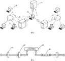
图1是本发明的网络连接示意图;Fig. 1 is a schematic diagram of network connection of the present invention;
图2是本发明的VPN网关服务器网关应用程序工作流程示意图;Fig. 2 is a schematic diagram of the workflow of the VPN gateway server gateway application program of the present invention;
图3是本发明的VPN网关服务器端到VPN网关服务器端隧道连接与资源访问示意图;Fig. 3 is VPN gateway server end to VPN gateway server end tunnel connection and resource access schematic diagram of the present invention;
图4是本发明的客户端到VPN网关服务器端隧道连接与资源访问示意图;Fig. 4 is a schematic diagram of tunnel connection and resource access from the client to the VPN gateway server end of the present invention;
图5是本发明的虚拟网卡工作原理示意图。Fig. 5 is a schematic diagram of the working principle of the virtual network card of the present invention.
具体实施方式Detailed ways
下面结合附图对本发明作进一步说明:The present invention will be further described below in conjunction with accompanying drawing:
如图1所示为本发明的网络连接示意图,其中应用服务器A①4、应用服务器A②5及用户A6通过网络A3与VPN网关服务器A2相连,应用服务器B①9、应用服务器B②10及用户B11通过网络B8与VPN网关服务器B7相连,VPN网关服务器之间及VPN网关服务器与中心服务器1之间有互联的隧道,移动客户端12与各VPN网关服务器和中心服务器1之间也有互联的隧道;As shown in Figure 1, it is the network connection schematic diagram of the present invention, wherein application server A 1. 4,
各网关服务器与中心服务器通信,报告自己代理的网络信息,中心服务器记录各个网关的入口IP地址信息及网络信息,并按照配置文件统一配置各个网络的虚拟IP地址空间。各网关服务器与移动客户端通过与中心服务器通信来获取各自需求的信息。Each gateway server communicates with the central server to report the network information of its own agent. The central server records the entrance IP address information and network information of each gateway, and uniformly configures the virtual IP address space of each network according to the configuration file. Each gateway server and mobile client obtain the information they need by communicating with the central server.
如图2所示为本发明的VPN网关服务器网关应用程序工作流程示意图,VPN网关服务器上网关应用程序启动后,先载入自身的配置文件,同时启动中心服务器通信模块和隧道通信模块,中心服务器模块与中心服务器通信报告自身网络信息,并获取其它VPN网关服务器的入口IP信息及代理的网络信息。隧道通信模块通过获取的信息,设置自身网络的映射关系,并建立起其它VPN网关服务器代理网络的路由关系。通过VPN网关服务器的入口IP信息进行网关间的隧道构建,并同时监听客户端的连接。对于内网与其它VPN网络间通信的数据包,通过本机路由功能将需要处理的数据包路由到虚拟网卡捕获,交由隧道通信模块处理。As shown in Figure 2, it is the VPN gateway server gateway application program workflow schematic diagram of the present invention, after the gateway application program starts on the VPN gateway server, it first loads its own configuration file, and starts the central server communication module and the tunnel communication module simultaneously, and the central server The module communicates with the central server to report its own network information, and obtains the entrance IP information of other VPN gateway servers and the network information of the agent. The tunnel communication module sets the mapping relationship of its own network through the obtained information, and establishes the routing relationship of other VPN gateway server proxy networks. Through the ingress IP information of the VPN gateway server, the tunnel between the gateways is constructed, and the connection of the client is monitored at the same time. For the data packets communicated between the intranet and other VPN networks, the data packets that need to be processed are routed to the virtual network card for capture through the local routing function, and then handed over to the tunnel communication module for processing.
如图3所示为本发明的VPN网关服务器端到VPN网关服务器端隧道连接与资源访问示意图,VPN网关服务器首先向中心服务器1请求各个VPN网关服务器的入口地址,用获取的入口地址连接到各个VPN网关服务器,并在相互之间建立隧道,同时获取网络中可用的资源信息,更新域名信息。VPN网络中网络A3中一台主机用户A6要求访问另一个网络网络B8中的资源,访问资源的网络数据包由操作系统路由到本地网络的VPN网关服务器A2,VPN网关服务器A2上的路由功能将数据包路由到虚拟网卡,虚拟网卡将数据包传送到网关应用程序,网关应用程序做一个IP地址的映射,并由数据包的目的地,将数据包发送到对应的隧道,数据包经隧道达到相应的应用服务器B①9所在的网络的VPN网关服务器B7,VPN网关服务器B7做一个IP地址的映射,将数据包发送到相应的应用服务器B①9;应用服务器B①9返回应答数据包路由到达VPN网关服务器B7,VPN网关服务器B7做一个IP地址的映射,将数据包发送到对应的隧道,VPN网关服务器A2接受到数据包后,再次做一个IP地址的映射,将数据包返回到用户A6。As shown in Figure 3, it is VPN gateway server end of the present invention to VPN gateway server end tunnel connection and resource access schematic diagram, VPN gateway server at first requests the entry address of each VPN gateway server to central server 1, connects to each with the entry address that obtains VPN gateway servers, and establish tunnels between each other, and at the same time obtain resource information available in the network, and update domain name information. In the VPN network, a host user A6 in the network A3 requests to access resources in another network network B8, and the network data packets for accessing the resources are routed by the operating system to the VPN gateway server A2 of the local network, and the routing function on the VPN gateway server A2 will The data packet is routed to the virtual network card, and the virtual network card transmits the data packet to the gateway application program. The gateway application program does an IP address mapping, and sends the data packet to the corresponding tunnel according to the destination of the data packet, and the data packet arrives through the tunnel. The VPN gateway server B7 of the network where the corresponding application server B 1. 9 is located, and the VPN gateway server B7 does an IP address mapping, and sends the data packet to the corresponding application server B 1. 9; the application server B 1. 9 returns the reply packet route and arrives at the VPN gateway server B7. The VPN gateway server B7 performs an IP address mapping, and sends the data packet to the corresponding tunnel. After the VPN gateway server A2 receives the data packet, it performs an IP address mapping again, and returns the data packet to the user A6.
如图4所示为本发明的移动客户端到VPN网关服务器端隧道连接与资源访问示意图,移动客户端12首先向中心服务器1请求VPN网关服务器的入口地址,用获取的入口地址连接到VPN网关服务器,并建立隧道,同时获取网络中可用的资源信息。移动客户端12的应用层要求访问资源,访问资源的网络数据包由用户A6的客户端软件发往VPN网关服务器A2,VPN网关服务器A2做一个IP地址的映射,将数据包发送到对应的应用服务器A①4,应用服务器A①4返回应答数据包到达VPN网关服务器A2,VPN网关服务器A2再次做一个IP地址的映射,将数据包返回到移动客户端12,客户端软件将数据包发往应用层。As shown in Fig. 4,
如图5所示为本发明的虚拟网卡工作原理示意图,VPN网关服务器上安装有一块虚拟网卡14,内网网卡15抓到的数据包,只有由上层网关应用程序13设置了路由的数据包,会路由到虚拟网卡14,虚拟网卡14将数据包发送到网关应用程序,交由网关应用程序作完映射处理,加密(或解密后)处理,发送到相应隧道的数据队列16中。As shown in Figure 5, it is a schematic diagram of the working principle of the virtual network card of the present invention. A
Claims (4)
Translated fromChinesePriority Applications (1)
| Application Number | Priority Date | Filing Date | Title |
|---|---|---|---|
| CN2007103043136ACN101197856B (en) | 2007-12-27 | 2007-12-27 | IP address space planning-free and private domain name access method in VPN network |
Applications Claiming Priority (1)
| Application Number | Priority Date | Filing Date | Title |
|---|---|---|---|
| CN2007103043136ACN101197856B (en) | 2007-12-27 | 2007-12-27 | IP address space planning-free and private domain name access method in VPN network |
Publications (2)
| Publication Number | Publication Date |
|---|---|
| CN101197856A CN101197856A (en) | 2008-06-11 |
| CN101197856Btrue CN101197856B (en) | 2011-04-20 |
Family
ID=39547997
Family Applications (1)
| Application Number | Title | Priority Date | Filing Date |
|---|---|---|---|
| CN2007103043136AExpired - Fee RelatedCN101197856B (en) | 2007-12-27 | 2007-12-27 | IP address space planning-free and private domain name access method in VPN network |
Country Status (1)
| Country | Link |
|---|---|
| CN (1) | CN101197856B (en) |
Families Citing this family (14)
| Publication number | Priority date | Publication date | Assignee | Title |
|---|---|---|---|---|
| CN101640607B (en)* | 2009-04-13 | 2012-02-22 | 山石网科通信技术(北京)有限公司 | Collocation method of virtual private network based on internet security protocol and system therefor |
| CN101964799B (en)* | 2010-10-21 | 2014-06-04 | 神州数码网络(北京)有限公司 | Solution method of address conflict in point-to-network tunnel mode |
| CN101997875B (en)* | 2010-10-29 | 2013-05-29 | 北京大学 | A secure multi-party network communication platform, its construction method, and communication method |
| TWI482469B (en) | 2012-05-23 | 2015-04-21 | Gemtek Technology Co Ltd | Routing device |
| CN103001890B (en)* | 2012-12-28 | 2016-06-29 | 上海伟视清数字技术有限公司 | A kind of method for network access control |
| JP6127622B2 (en)* | 2013-03-18 | 2017-05-17 | ヤマハ株式会社 | DNS server device, network device, and communication system |
| CN103236950B (en)* | 2013-05-10 | 2015-12-02 | 烽火通信科技股份有限公司 | For the service management device of L3VPN |
| CN106027354B (en)* | 2016-05-19 | 2019-03-15 | 杭州迪普科技股份有限公司 | The reflow method and device of VPN client |
| CN111786868B (en)* | 2019-04-04 | 2022-04-22 | 厦门网宿有限公司 | Data transmission method between servers and strongswan server |
| CN110545308A (en)* | 2019-08-05 | 2019-12-06 | 无锡华云数据技术服务有限公司 | Server connection method, resource downloading method, device, electronic equipment and medium |
| CN110943999B (en)* | 2019-12-05 | 2022-03-22 | 拉货宝网络科技有限责任公司 | Logistics multi-bin network intercommunication and monitoring method |
| CN112087361A (en)* | 2020-09-17 | 2020-12-15 | 宏图智能物流股份有限公司 | Method for realizing butt joint of different warehouse network platforms |
| CN112104763A (en)* | 2020-09-17 | 2020-12-18 | 宏图智能物流股份有限公司 | Method for realizing butt joint of different network platforms in warehouse |
| CN113300932A (en)* | 2021-05-25 | 2021-08-24 | 上海金途信息科技有限公司 | Wide area network multi-terminal management system based on reverse proxy and virtual link realization |
- 2007
- 2007-12-27CNCN2007103043136Apatent/CN101197856B/ennot_activeExpired - Fee Related
Also Published As
| Publication number | Publication date |
|---|---|
| CN101197856A (en) | 2008-06-11 |
Similar Documents
| Publication | Publication Date | Title |
|---|---|---|
| CN101197856B (en) | IP address space planning-free and private domain name access method in VPN network | |
| CN114374581B (en) | Enterprise Virtual Private Network (VPN) to Virtual Private Cloud (VPC) adhesion | |
| CN113950816B (en) | System and method for providing a multi-cloud micro-service gateway using a side car agency | |
| US8407366B2 (en) | Interconnecting members of a virtual network | |
| EP2586160B1 (en) | Distributed virtual network gateways | |
| CN101222406B (en) | Method for application level content routing in virtual private network (VPN) using dual-proxy method | |
| CN103023898B (en) | A kind of method and device of accessing VPN service end Intranet resource | |
| CN109155799A (en) | The subnet extension communicated via layer three | |
| CN104427010A (en) | NAT (network address translation) method and device applied to DVPN (dynamic virtual private network) | |
| KR20080026161A (en) | Unified Architecture for Remote Network Access | |
| JP6211975B2 (en) | Network extension system, control device, and network extension method | |
| CN100490393C (en) | Method for accessing user network management platform | |
| CN103873372A (en) | Policy routing system and setting method based on domain name | |
| JP2003167805A (en) | Network communication method and server device between multiple user side closed network and server side closed network | |
| JP2004153366A (en) | Virtual private network (VPN) system and relay node | |
| Grasa et al. | Seamless network renumbering in rina: Automate address changes without breaking flows! | |
| CN111466134A (en) | Method and arrangement for allocating communication resources in a communication network | |
| Liu et al. | Dynamic configuration for IPv4/IPv6 address mapping in 4over6 technology | |
| WO2025051027A1 (en) | Traffic policy determination method, electronic device, and storage medium | |
| CN119484386A (en) | Computing power service access method, system and node information uploading method of computing power service |
Legal Events
| Date | Code | Title | Description |
|---|---|---|---|
| C06 | Publication | ||
| PB01 | Publication | ||
| C10 | Entry into substantive examination | ||
| SE01 | Entry into force of request for substantive examination | ||
| C14 | Grant of patent or utility model | ||
| GR01 | Patent grant | ||
| C17 | Cessation of patent right | ||
| CF01 | Termination of patent right due to non-payment of annual fee | Granted publication date:20110420 Termination date:20121227 |