CN101192640A - Light-emitting diode with heat radiating device - Google Patents
Light-emitting diode with heat radiating deviceDownload PDFInfo
- Publication number
- CN101192640A CN101192640ACNA2006101640123ACN200610164012ACN101192640ACN 101192640 ACN101192640 ACN 101192640ACN A2006101640123 ACNA2006101640123 ACN A2006101640123ACN 200610164012 ACN200610164012 ACN 200610164012ACN 101192640 ACN101192640 ACN 101192640A
- Authority
- CN
- China
- Prior art keywords
- led
- heat sink
- liquid
- emitting diode
- insulating plate
- Prior art date
- Legal status (The legal status is an assumption and is not a legal conclusion. Google has not performed a legal analysis and makes no representation as to the accuracy of the status listed.)
- Pending
Links
Images


Classifications
- H—ELECTRICITY
- H10—SEMICONDUCTOR DEVICES; ELECTRIC SOLID-STATE DEVICES NOT OTHERWISE PROVIDED FOR
- H10H—INORGANIC LIGHT-EMITTING SEMICONDUCTOR DEVICES HAVING POTENTIAL BARRIERS
- H10H20/00—Individual inorganic light-emitting semiconductor devices having potential barriers, e.g. light-emitting diodes [LED]
- H10H20/80—Constructional details
- H10H20/85—Packages
- H10H20/858—Means for heat extraction or cooling
- H10H20/8586—Means for heat extraction or cooling comprising fluids, e.g. heat-pipes
- F—MECHANICAL ENGINEERING; LIGHTING; HEATING; WEAPONS; BLASTING
- F28—HEAT EXCHANGE IN GENERAL
- F28D—HEAT-EXCHANGE APPARATUS, NOT PROVIDED FOR IN ANOTHER SUBCLASS, IN WHICH THE HEAT-EXCHANGE MEDIA DO NOT COME INTO DIRECT CONTACT
- F28D15/00—Heat-exchange apparatus with the intermediate heat-transfer medium in closed tubes passing into or through the conduit walls ; Heat-exchange apparatus employing intermediate heat-transfer medium or bodies
- F28D15/02—Heat-exchange apparatus with the intermediate heat-transfer medium in closed tubes passing into or through the conduit walls ; Heat-exchange apparatus employing intermediate heat-transfer medium or bodies in which the medium condenses and evaporates, e.g. heat pipes
- F28D15/0233—Heat-exchange apparatus with the intermediate heat-transfer medium in closed tubes passing into or through the conduit walls ; Heat-exchange apparatus employing intermediate heat-transfer medium or bodies in which the medium condenses and evaporates, e.g. heat pipes the conduits having a particular shape, e.g. non-circular cross-section, annular
- F—MECHANICAL ENGINEERING; LIGHTING; HEATING; WEAPONS; BLASTING
- F28—HEAT EXCHANGE IN GENERAL
- F28D—HEAT-EXCHANGE APPARATUS, NOT PROVIDED FOR IN ANOTHER SUBCLASS, IN WHICH THE HEAT-EXCHANGE MEDIA DO NOT COME INTO DIRECT CONTACT
- F28D15/00—Heat-exchange apparatus with the intermediate heat-transfer medium in closed tubes passing into or through the conduit walls ; Heat-exchange apparatus employing intermediate heat-transfer medium or bodies
- F28D15/02—Heat-exchange apparatus with the intermediate heat-transfer medium in closed tubes passing into or through the conduit walls ; Heat-exchange apparatus employing intermediate heat-transfer medium or bodies in which the medium condenses and evaporates, e.g. heat pipes
- F28D15/04—Heat-exchange apparatus with the intermediate heat-transfer medium in closed tubes passing into or through the conduit walls ; Heat-exchange apparatus employing intermediate heat-transfer medium or bodies in which the medium condenses and evaporates, e.g. heat pipes with tubes having a capillary structure
- F—MECHANICAL ENGINEERING; LIGHTING; HEATING; WEAPONS; BLASTING
- F21—LIGHTING
- F21K—NON-ELECTRIC LIGHT SOURCES USING LUMINESCENCE; LIGHT SOURCES USING ELECTROCHEMILUMINESCENCE; LIGHT SOURCES USING CHARGES OF COMBUSTIBLE MATERIAL; LIGHT SOURCES USING SEMICONDUCTOR DEVICES AS LIGHT-GENERATING ELEMENTS; LIGHT SOURCES NOT OTHERWISE PROVIDED FOR
- F21K9/00—Light sources using semiconductor devices as light-generating elements, e.g. using light-emitting diodes [LED] or lasers
- H—ELECTRICITY
- H01—ELECTRIC ELEMENTS
- H01L—SEMICONDUCTOR DEVICES NOT COVERED BY CLASS H10
- H01L2224/00—Indexing scheme for arrangements for connecting or disconnecting semiconductor or solid-state bodies and methods related thereto as covered by H01L24/00
- H01L2224/01—Means for bonding being attached to, or being formed on, the surface to be connected, e.g. chip-to-package, die-attach, "first-level" interconnects; Manufacturing methods related thereto
- H01L2224/42—Wire connectors; Manufacturing methods related thereto
- H01L2224/47—Structure, shape, material or disposition of the wire connectors after the connecting process
- H01L2224/48—Structure, shape, material or disposition of the wire connectors after the connecting process of an individual wire connector
- H01L2224/4805—Shape
- H01L2224/4809—Loop shape
- H01L2224/48091—Arched
- H—ELECTRICITY
- H01—ELECTRIC ELEMENTS
- H01L—SEMICONDUCTOR DEVICES NOT COVERED BY CLASS H10
- H01L2224/00—Indexing scheme for arrangements for connecting or disconnecting semiconductor or solid-state bodies and methods related thereto as covered by H01L24/00
- H01L2224/01—Means for bonding being attached to, or being formed on, the surface to be connected, e.g. chip-to-package, die-attach, "first-level" interconnects; Manufacturing methods related thereto
- H01L2224/42—Wire connectors; Manufacturing methods related thereto
- H01L2224/47—Structure, shape, material or disposition of the wire connectors after the connecting process
- H01L2224/48—Structure, shape, material or disposition of the wire connectors after the connecting process of an individual wire connector
- H01L2224/484—Connecting portions
- H01L2224/48463—Connecting portions the connecting portion on the bonding area of the semiconductor or solid-state body being a ball bond
- H01L2224/48465—Connecting portions the connecting portion on the bonding area of the semiconductor or solid-state body being a ball bond the other connecting portion not on the bonding area being a wedge bond, i.e. ball-to-wedge, regular stitch
- H—ELECTRICITY
- H01—ELECTRIC ELEMENTS
- H01L—SEMICONDUCTOR DEVICES NOT COVERED BY CLASS H10
- H01L25/00—Assemblies consisting of a plurality of semiconductor or other solid state devices
- H01L25/03—Assemblies consisting of a plurality of semiconductor or other solid state devices all the devices being of a type provided for in a single subclass of subclasses H10B, H10D, H10F, H10H, H10K or H10N, e.g. assemblies of rectifier diodes
- H01L25/04—Assemblies consisting of a plurality of semiconductor or other solid state devices all the devices being of a type provided for in a single subclass of subclasses H10B, H10D, H10F, H10H, H10K or H10N, e.g. assemblies of rectifier diodes the devices not having separate containers
- H01L25/075—Assemblies consisting of a plurality of semiconductor or other solid state devices all the devices being of a type provided for in a single subclass of subclasses H10B, H10D, H10F, H10H, H10K or H10N, e.g. assemblies of rectifier diodes the devices not having separate containers the devices being of a type provided for in group H10H20/00
- H01L25/0753—Assemblies consisting of a plurality of semiconductor or other solid state devices all the devices being of a type provided for in a single subclass of subclasses H10B, H10D, H10F, H10H, H10K or H10N, e.g. assemblies of rectifier diodes the devices not having separate containers the devices being of a type provided for in group H10H20/00 the devices being arranged next to each other
Landscapes
- Engineering & Computer Science (AREA)
- Life Sciences & Earth Sciences (AREA)
- Sustainable Development (AREA)
- Physics & Mathematics (AREA)
- Thermal Sciences (AREA)
- Mechanical Engineering (AREA)
- General Engineering & Computer Science (AREA)
- Led Devices (AREA)
- Led Device Packages (AREA)
- Cooling Or The Like Of Semiconductors Or Solid State Devices (AREA)
Abstract
Description
Translated fromChinese技术领域technical field
本发明系与LED(发光二极管)有关,特别是指具有良好导热/散热功效的一种带散热装置的发光二极管。The present invention is related to LED (Light Emitting Diode), in particular to a light emitting diode with heat dissipation device having good heat conduction/radiation effect.
背景技术Background technique
自蓝光LED问世后,LED的应用已进入新的阶段,全彩显示已成为可行,现今全彩高亮度LED大型显示屏,已极为普遍。然而高亮度LED在工作时,会产生高热,其散热问题在目前为止并未有良好的解决方式。Since the advent of blue LED, the application of LED has entered a new stage, and full-color display has become feasible. Nowadays, large-scale full-color high-brightness LED displays are very common. However, high-brightness LEDs will generate high heat during operation, and there is no good solution to the heat dissipation problem so far.
美国专利第US5,173,839号专利,即提出了一种解决LED显示器的散热问题的技术,其中,其LED晶片下方系由一导热带、一铝块、一导热带以及一散热片所迭置而成,而将LED晶片所产生的热能经由下方导出。惟,此种技术中,真正会产生热的LED晶片与散热片之间还隔着三层物质,其中介层太多,不仅热阻(温阻)较大,且散热速度也较慢,并非良好的解决方式。U.S. Patent No. US5,173,839 proposes a technology to solve the heat dissipation problem of LED displays, wherein the bottom of the LED chip is stacked by a heat conduction tape, an aluminum block, a heat conduction tape and a heat sink. As a result, the heat energy generated by the LED chip is exported through the bottom. However, in this technology, there are three layers of material between the LED chip that actually generates heat and the heat sink. There are too many interlayers, not only the thermal resistance (temperature resistance) is large, but the heat dissipation speed is also slow. good solution.
又,台湾专利第M295889号专利,亦提出了一种解决LED的散热问题的技术,其主要是将LED设置于一散热管上,其LED中包含了LED塑料绝缘电路板,LED晶座,LED发热芯片,LED透光镜片所组成。惟,此种技术虽使用了导热效率较高的散热管来导热,然而,在LED发热芯片与散热管之间,仍具有中介层-LED晶座以及LED塑料绝缘电路板,亦即,同样有热阻较大而散热速度较慢的问题。Also, the Taiwan Patent No. M295889 patent also proposes a technology to solve the heat dissipation problem of LEDs. It is mainly to arrange the LEDs on a heat pipe, and the LEDs include LED plastic insulating circuit boards, LED crystal seats, LED Composed of heating chips and LED transparent lenses. However, although this technology uses a heat dissipation pipe with high thermal conductivity to conduct heat, there is still an intermediary layer between the LED heating chip and the heat dissipation pipe-LED crystal base and LED plastic insulating circuit board, that is, there are also The problem of large thermal resistance and slow heat dissipation.
发明内容Contents of the invention
本发明的主要目的在于提供一种带散热装置的发光二极管,其可对LED所产生的热能提供一较佳的散热效果。The main purpose of the present invention is to provide a light-emitting diode with a cooling device, which can provide a better cooling effect on the heat generated by the LED.
缘是,为了达成前述目的,依据本发明所提供的一种带散热装置的发光二极管,包含有:一液汽相散热装置,主要具有一金属壳体,内部并具有预定量液体及毛细构造;以及至少一LED单元,设于该金属壳体表面;该LED单元主要由一LED晶片、一连接线、一绝缘板、一电极片以及一封胶所组成;其中,该LED晶片植于该金属壳体表面而与该金属壳体电性导通,该绝缘板置于该金属壳体表面,该电极片位于该绝缘板上该连接线以其两端分别连接于该LED晶片以及该电极片上,该封胶将该连接线以及该LED晶片包覆,并至少局部包覆该绝缘板及该电极片。藉此,可使LED晶片所产生的热能直接传导至该液汽相散热装置,不会有其它中介层所产生的热阻,而可具有更好的导热/散热效果。The reason is that, in order to achieve the above-mentioned purpose, according to the present invention, a light-emitting diode with heat dissipation device includes: a liquid-vapor phase heat dissipation device, which mainly has a metal shell, and has a predetermined amount of liquid and capillary structure inside; And at least one LED unit is arranged on the surface of the metal shell; the LED unit is mainly composed of an LED chip, a connecting wire, an insulating plate, an electrode sheet and a sealing glue; wherein, the LED chip is planted on the metal The surface of the shell is electrically connected to the metal shell, the insulating plate is placed on the surface of the metal shell, the electrode piece is located on the insulating plate, and the two ends of the connecting wire are respectively connected to the LED chip and the electrode piece , the sealant covers the connecting wire and the LED chip, and at least partially covers the insulating plate and the electrode sheet. Thereby, the heat energy generated by the LED chip can be directly conducted to the liquid-vapor heat dissipation device, without the thermal resistance generated by other intermediary layers, and better heat conduction/radiation effect can be achieved.
附图说明Description of drawings
图1是本发明第一较佳实施例的立体图。Fig. 1 is a perspective view of the first preferred embodiment of the present invention.
图2是本发明第一较佳实施例的俯视图。Fig. 2 is a top view of the first preferred embodiment of the present invention.
图3是沿图2中3-3剖线的剖视图。Fig. 3 is a cross-sectional view along line 3-3 in Fig. 2 .
图4是本发明第二较佳实施例的立体图。Fig. 4 is a perspective view of a second preferred embodiment of the present invention.
图5是本发明第三较佳实施例的立体图。Fig. 5 is a perspective view of a third preferred embodiment of the present invention.
图6是本发明第三较佳实施例的俯视图。Fig. 6 is a top view of a third preferred embodiment of the present invention.
图7是沿图6中7-7剖线的剖视图。Fig. 7 is a cross-sectional view along line 7-7 in Fig. 6 .
图8是本发明第四较佳实施例的立体图。Fig. 8 is a perspective view of a fourth preferred embodiment of the present invention.
具体实施方式Detailed ways
为了详细说明本发明的构造及特点所在,兹举以下四较佳实施例并配合附图说明如后,其中:In order to describe the structure and characteristics of the present invention in detail, the following four preferred embodiments are given below and are described as follows in conjunction with the accompanying drawings, wherein:
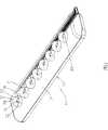
如图1至图3所示,本发明第一较佳实施例所提供的一种带散热装置的发光二极管10,主要由一液汽相散热装置11以及数个LED单元21所组成,其中:As shown in Figures 1 to 3, a light-
该液汽相散热装置11,主要有一金属壳体12,在本实施例为散热管,其为铜材质,该液汽相散热装置11的内部并具有预定量液体14以及毛细构造16,该毛细构造16可为烧结的铜粉或网状结构或于金属壳体12内壁面所形成的沟槽。而液汽相散热装置11的内部结构属公知技术,容不再予赘述。The liquid-vapor
该等LED单元21,以线状排列方式排列于该液汽相散热装置11的金属壳体12表面。The
而本发明的特点在于:And the present invention is characterized in that:
该LED单元21主要由一LED晶片22、一连接线24、一绝缘板26、一电极片28以及一封胶29所组成。其中,该LED晶片22植于该金属壳体12表面而与该金属壳体12电性导通,该绝缘板26置于该金属壳体12表面,该电极片28位于该绝缘板26上,该连接线24以其两端分别连接于该LED晶片22以及该电极片28上,该封胶29将该连接线24以及该LED晶片22包覆,并且局部包覆该绝缘板26以及该电极片28,亦即,该电极片28有局部外露于该封胶29。The
该等LED单元21的绝缘板26以及电极片28可由同一绝缘板26上设置对应数量的电极片28所形成,而联合形成一电路板288。藉此,该等LED单元21的LED晶片22均电性连接于该金属壳体12(即负极),而该连接线24则连接于该电极片28(即正极)外露于该封胶29,形成于该电路板288上的接点,而可供连接通电来控制LED晶片22发光之用。The
本第一实施例于实际使用时,系可藉由其它电子驱动装置(图未示)连接于该电路板288,藉由各该LED单元21的电极片28来通电驱动各该LED晶片22发光,而各该LED晶片22系电性连接于该金属壳体12,该金属壳体12即为共享的负极。而各该LED晶片22在发光时所产生的热能即直接传递至该金属壳体12上,藉由液汽相散热装置11本身的高导热性,能几乎立即性的将热能导出,藉此可对LED晶片22进行极佳的导热/散热的效果。In the actual use of the first embodiment, other electronic drive devices (not shown) can be connected to the
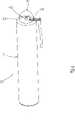
请再参阅图4,本发明第二较佳实施例所提供的一种带散热装置的发光二极管30,主要概同于前揭第一实施例,不同之处在于:Please refer to Fig. 4 again, a light-emitting
该液汽相散热装置31的一端具有一端面32,该LED单元41设于该端面32上。One end of the liquid-
藉由对该电极片48通电即可驱动该LED单元41的LED晶片42发光,而热能亦同样的藉由该液汽相散热装置31来进行导热/散热。The
本第二实施例的使用方式及功效系概同于前揭第一实施例,容不赘述。The use method and effect of this second embodiment are generally the same as those of the first embodiment disclosed above, and will not be described in detail.
再如图5至图7所示,本发明第三实施例所提供的一种带散热装置的发光二极管50,主要概同于前揭第一实施例,不同之处在于:As shown in Fig. 5 to Fig. 7, a light-
该液汽相散热装置51为一扁形腔室。The liquid-vapor
该等LED单元61系为多数,而以矩阵方式排列于该液汽相散热装置51上,该等LED单元61的绝缘板66以及电极片68可由同一绝缘板66上设置对应数量的电极片68所形成,而联合形成该电路板688。The
本第三实施例的使用方式及所达成功效与第一实施例相同,容不赘述。The use method and achieved effects of the third embodiment are the same as those of the first embodiment, and will not be repeated here.
再如图8所示,本发明第四实施例所提供的一种带散热装置的发光二极管70,主要概同于前揭第一实施例,不同之处在于:As shown in Figure 8 again, a light-emitting diode 70 with a cooling device provided by the fourth embodiment of the present invention is basically the same as the first embodiment disclosed above, except that:
该液汽相散热装置71(散热管)系连接一散热片711。The liquid-vapor heat dissipation device 71 (heat dissipation pipe) is connected to a heat dissipation fin 711 .
藉此可将该等LED单元81的热能传导至该散热片711,来藉由该散热片711的大面积进行更好的散热。In this way, the thermal energy of the LED units 81 can be conducted to the heat sink 711 , and the large area of the heat sink 711 can be used for better heat dissipation.
本第四实施例的其它使用方式及所达成功效与第一实施例相同,容不赘述。Other ways of using and achieved effects of this fourth embodiment are the same as those of the first embodiment, and will not be repeated here.
由上可知,本发明所可达成的功效在于:As can be seen from the above, the effect that the present invention can achieve is:
散热效果更好:相较于公知技术而言,本发明在LED晶片与液汽相散热装置之间,省略了中介层-晶座及电路板,此意味着大幅度的减少了热阻,LED晶片所产生的热能直接的由该液汽相散热装置所传导出去,而具有优于公知技术的散热效果。Better heat dissipation effect: Compared with the known technology, the present invention omits the intermediary layer-socket and circuit board between the LED chip and the liquid-vapor heat dissipation device, which means that the thermal resistance is greatly reduced, and the LED The heat energy generated by the chip is directly conducted out by the liquid-vapor heat dissipation device, so that the heat dissipation effect is better than that of the known technology.
Claims (8)
Translated fromChinesePriority Applications (2)
| Application Number | Priority Date | Filing Date | Title |
|---|---|---|---|
| CNA2006101640123ACN101192640A (en) | 2006-11-22 | 2006-11-22 | Light-emitting diode with heat radiating device |
| EP07006411AEP1926152A2 (en) | 2006-11-22 | 2007-03-28 | Combination assembly of light emitting diode and liquid-vapor thermally dissipating device |
Applications Claiming Priority (1)
| Application Number | Priority Date | Filing Date | Title |
|---|---|---|---|
| CNA2006101640123ACN101192640A (en) | 2006-11-22 | 2006-11-22 | Light-emitting diode with heat radiating device |
Publications (1)
| Publication Number | Publication Date |
|---|---|
| CN101192640Atrue CN101192640A (en) | 2008-06-04 |
Family
ID=39032369
Family Applications (1)
| Application Number | Title | Priority Date | Filing Date |
|---|---|---|---|
| CNA2006101640123APendingCN101192640A (en) | 2006-11-22 | 2006-11-22 | Light-emitting diode with heat radiating device |
Country Status (2)
| Country | Link |
|---|---|
| EP (1) | EP1926152A2 (en) |
| CN (1) | CN101192640A (en) |
Cited By (2)
| Publication number | Priority date | Publication date | Assignee | Title |
|---|---|---|---|---|
| CN101847679A (en)* | 2009-04-02 | 2010-09-29 | 刘春� | Isothermal body heat radiation substrate of LED luminous body and isothermal body heat radiation method of LED luminous body |
| WO2011035526A1 (en)* | 2009-09-24 | 2011-03-31 | Wang Chunyan | High power led lamp |
Families Citing this family (1)
| Publication number | Priority date | Publication date | Assignee | Title |
|---|---|---|---|---|
| CN101943378B (en)* | 2009-07-08 | 2012-03-28 | 国格金属科技股份有限公司 | Compression device |
- 2006
- 2006-11-22CNCNA2006101640123Apatent/CN101192640A/enactivePending
- 2007
- 2007-03-28EPEP07006411Apatent/EP1926152A2/ennot_activeWithdrawn
Cited By (2)
| Publication number | Priority date | Publication date | Assignee | Title |
|---|---|---|---|---|
| CN101847679A (en)* | 2009-04-02 | 2010-09-29 | 刘春� | Isothermal body heat radiation substrate of LED luminous body and isothermal body heat radiation method of LED luminous body |
| WO2011035526A1 (en)* | 2009-09-24 | 2011-03-31 | Wang Chunyan | High power led lamp |
Also Published As
| Publication number | Publication date |
|---|---|
| EP1926152A2 (en) | 2008-05-28 |
Similar Documents
| Publication | Publication Date | Title |
|---|---|---|
| TWI322915B (en) | Heat dissipation structure of backliht module | |
| JP3131390U (en) | Connection structure of LED and heat dissipation sheet | |
| US7538356B2 (en) | Combination assembly of LED and liquid-vapor thermally dissipating device | |
| CN100464411C (en) | Light-emitting diode packaging structure and packaging method | |
| CN101776248B (en) | Lamps and lighting devices | |
| US7611263B2 (en) | Light source module with a thermoelectric cooler | |
| CN101198216A (en) | Flexible circuit board for LED lighting array | |
| TWI363161B (en) | Light emitting diode lighting module with improved heat dissipation structure | |
| TW200847468A (en) | Heat-dissipating substrates for light-emitting diodes | |
| TWI572818B (en) | Heat dispersion structure and manufacturing method thereof | |
| WO2011057433A1 (en) | Light emitting diode lamp bar and manufacture method thereof, light emitting diode lamp tube | |
| CN101222007A (en) | Luminous diode with radiator | |
| TW201124774A (en) | LED device and display | |
| CN101126863A (en) | Light-emitting diode light source module with heat radiation structure | |
| TW200830583A (en) | Combined assembly of LED and liquid/gas phase heat dissipation device | |
| TW200830584A (en) | Combined assembly of LED and liquid/gas phase heat dissipation device | |
| CN201550394U (en) | Heat sink with heat pipe and uniform temperature plate | |
| CN202631938U (en) | Laser light source and related projection system | |
| JP5558930B2 (en) | LED element heat dissipation structure | |
| CN101222006A (en) | LED with radiator | |
| CN101192640A (en) | Light-emitting diode with heat radiating device | |
| US20070131448A1 (en) | Circuit board structure with heat radiating layer | |
| CN104244581A (en) | High heat conduction apparatus for multilayer circuit | |
| CN109216300B (en) | Combined substrate structure | |
| CN101783341B (en) | LED light source module with heat dissipation structure |
Legal Events
| Date | Code | Title | Description |
|---|---|---|---|
| C06 | Publication | ||
| PB01 | Publication | ||
| C10 | Entry into substantive examination | ||
| SE01 | Entry into force of request for substantive examination | ||
| C02 | Deemed withdrawal of patent application after publication (patent law 2001) | ||
| WD01 | Invention patent application deemed withdrawn after publication |