CN101192078B - Portable computer device - Google Patents
Portable computer deviceDownload PDFInfo
- Publication number
- CN101192078B CN101192078BCN200610160710ACN200610160710ACN101192078BCN 101192078 BCN101192078 BCN 101192078BCN 200610160710 ACN200610160710 ACN 200610160710ACN 200610160710 ACN200610160710 ACN 200610160710ACN 101192078 BCN101192078 BCN 101192078B
- Authority
- CN
- China
- Prior art keywords
- display
- portable computer
- extraction module
- computer device
- image
- Prior art date
- Legal status (The legal status is an assumption and is not a legal conclusion. Google has not performed a legal analysis and makes no representation as to the accuracy of the status listed.)
- Active
Links
- 238000000605extractionMethods0.000claimsabstractdescription28
- 230000000007visual effectEffects0.000abstract1
- 238000010586diagramMethods0.000description3
- 238000000034methodMethods0.000description3
- 230000008901benefitEffects0.000description2
- 230000007246mechanismEffects0.000description2
- 239000004973liquid crystal related substanceSubstances0.000description1
- 238000012986modificationMethods0.000description1
- 230000004048modificationEffects0.000description1
- 230000008569processEffects0.000description1
Images


Landscapes
- Devices For Indicating Variable Information By Combining Individual Elements (AREA)
- Telephone Set Structure (AREA)
Abstract
Description
Translated fromChinese技术领域technical field
本发明涉及一种便携式计算机装置,特别是涉及一种具有可水平旋转的图像提取模块的便携式计算机装置。The invention relates to a portable computer device, in particular to a portable computer device with a horizontally rotatable image extraction module.
背景技术Background technique
随着科技的发展,便携式计算机装置(例如笔记本计算机)已逐渐地取代台式计算机。目前,在一些中高阶机种的便携式计算机装置中通常会配备有图像提取模块,以提供使用者通过图像提取模块来与远程的用户互动,或是用来录制使用者个人的影音画面。With the development of technology, portable computer devices (such as notebook computers) have gradually replaced desktop computers. At present, some middle and high-end portable computer devices are usually equipped with an image capture module to allow users to interact with remote users through the image capture module, or to record the user's personal video and audio images.
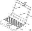
图1所示为公知的一种具有图像提取模块的笔记本计算机的立体示意图。参考图1,笔记本计算机100主要包括主机110以及枢接于主机110一侧的显示器120。一般来说,图像提取模块130是设置于笔记本计算机100的显示器120上,以便在视讯会议中提取使用者的图像。图像提取模块130包括图像提取装置132以及枢转机构134,图像提取装置132通过枢转机构134枢设于显示器120上,并使图像提取装置132可沿转轴A相对于笔记本计算机100进行垂直旋转。FIG. 1 is a schematic perspective view of a known notebook computer with an image extraction module. Referring to FIG. 1 , the
然而,在视讯会议进行的过程中,如有一群人围绕在笔记本计算机100前方进行讨论时,由于图像提取装置132的视角较小,因此,其仅能提取到位于图像提取装置132正前方的使用者的图像。如果要提取其它位于角落的使用者的图像时,则需要移动笔记本计算机100的位置,以提取到其它位于角落的使用者的图像。此外,当图像提取装置132被翻转180度,以提取到面对笔记本计算机100的外壳的使用者的图像时,图像提取装置132所提取到的图像会是一倒立的图像,因此,需要一额外的切换装置,以处理图像倒立的问题。However, during the video conference, if a group of people are discussing around the front of the
再有,笔记本计算机100上可使用的空间有限,为缩小笔记本计算机100上的组件尺寸,图像提取模块130的尺寸也不会做得太大,而此举将造成使用者在旋转图像提取模块130时,容易有操作不流畅的问题产生。Furthermore, the available space on the
发明内容Contents of the invention
本发明的目的是提供一种便携式计算机装置,该便携式计算机装置具有可水平旋转360度的图像提取模块,以解决公知的便携式计算机装置中其图像提取模块的视角不足,以及当其翻转至便携式计算机装置外壳时所遭遇到的图像倒立的问题。The purpose of this invention is to provide a kind of portable computer device, and this portable computer device has the image capture module that can rotate 360 degrees horizontally, to solve the insufficient viewing angle of its image capture module in the known portable computer device, and when it is turned over to the portable computer The problem of image inversion encountered when installing the shell.
为达到上述或其它目的,本发明提出一种便携式计算机装置,其包括主机、显示器、及图像提取模块。显示器的一侧枢接于主机的一侧,使其可沿着第一旋转轴向相对于主机开合。图像提取模块设置于显示器上,其中图像提取模块枢接于显示器上,且图像提取模块可沿着第二旋转轴向相对于显示器旋转,第二旋转轴向实质上垂直于第一旋转轴向。To achieve the above and other objectives, the present invention provides a portable computer device, which includes a host, a display, and an image capture module. One side of the display is pivotally connected to one side of the host so that it can be opened and closed relative to the host along the first rotation axis. The image capture module is disposed on the display, wherein the image capture module is pivotally connected to the display, and the image capture module can rotate relative to the display along a second rotation axis, and the second rotation axis is substantially perpendicular to the first rotation axis.
在本发明的一实施例中,该便携式计算机装置还包括转轴结构。此转轴结构包括第一枢接部和第二枢接部,其中第一枢接部固定于显示器上,第二枢接部固定于图像提取模块上,且第二枢接部可带动图像提取模块相对固定于显示器上的第一枢接部旋转。更进一步地说,上述的第一枢接部为转轴,第二枢接部为轴套,且转轴紧配于轴套中。In an embodiment of the invention, the portable computer device further includes a hinge structure. The hinge structure includes a first pivot joint and a second pivot joint, wherein the first pivot joint is fixed on the display, the second pivot joint is fixed on the image capture module, and the second pivot joint can drive the image capture module and rotate relative to the first pivot part fixed on the display. Furthermore, the above-mentioned first pivotal part is a rotating shaft, the second pivotal part is a shaft sleeve, and the rotating shaft is tightly fitted in the shaft sleeve.
在本发明的一实施例中,该便携式计算机装置还包括夹片式转轴结构。图像提取模块通过夹片式转轴结构相对于显示器旋转。In an embodiment of the present invention, the portable computer device further includes a clip-type hinge structure. The image extraction module rotates relative to the display through a clip-type rotating shaft structure.
在本发明的一实施例中,该便携式计算机装置还包括辅助转轴,设置于图像提取模块与显示器之间,以容置用以电连接图像提取模块和主机的导线。更进一步地说,辅助转轴由一中空柱体形成。In an embodiment of the present invention, the portable computer device further includes an auxiliary rotating shaft disposed between the image capture module and the display for accommodating wires for electrically connecting the image capture module and the host. Furthermore, the auxiliary shaft is formed by a hollow cylinder.
综上所述,本发明优选实施例的便携式计算机装置设置有一枢接于其显示器上的图像提取模块(即网络摄影机),图像提取模块可相对于显示器进行360度的水平旋转。这样,当视讯会议进行的过程中,如要提取其它位于角落的使用者的图像时,只需要水平旋转图像提取模块使其朝向发言中的使用者即可,以达到增加视角的目的。To sum up, the portable computer device in the preferred embodiment of the present invention is provided with an image capture module (ie, a network camera) pivotally connected to its display, and the image capture module can rotate 360 degrees horizontally relative to the display. In this way, when the image of other users in the corner is to be extracted during the video conference, the image extraction module only needs to be rotated horizontally so that it faces the speaking user, so as to increase the viewing angle.
此外,由于图像提取模块的旋转方式为水平旋转,因此,当图像提取模块向后旋转180度,以提取到面对便携式计算机装置的外壳的使用者的图像时,其所提取到的图像仍是一般正常的图像,而非一倒立的图像。In addition, since the rotation mode of the image capture module is horizontal rotation, when the image capture module is rotated 180 degrees backward to capture the image of the user facing the casing of the portable computer device, the captured image is still Generally normal image, not an inverted image.
再有,图像提取模块可利用微型化轴向式转轴结构或是微型化夹片式转轴结构而枢接于便携式计算机装的显示器上,由于其具有尺寸较小的优点,因此,将有助于提升旋转图像提取模块时的流畅度。Furthermore, the image extraction module can be pivotally connected to the display of the portable computer by utilizing a miniaturized axial shaft structure or a miniaturized clip-type shaft structure. Because it has the advantage of smaller size, it will help Improve the fluency when rotating the image extraction module.
为使本发明的上述和其它目的、特征和优点能更明显易于理解,下面特举优选实施例并配合附图作详细说明。In order to make the above and other objects, features and advantages of the present invention more obvious and easy to understand, preferred embodiments are specifically cited below and described in detail with accompanying drawings.
附图说明Description of drawings
图1所示为已知的一种具有图像提取模块的笔记本计算机的立体示意图;Fig. 1 is a known three-dimensional schematic view of a notebook computer with an image extraction module;
图2所示为根据本发明的一实施例的一种便携式计算机装置的立体示意图;FIG. 2 is a schematic perspective view of a portable computer device according to an embodiment of the present invention;
图3A和图3B所示为图2中的图像提取模块旋转某一角度时的立体示意图;FIG. 3A and FIG. 3B are perspective schematic diagrams when the image extraction module in FIG. 2 is rotated at a certain angle;
图4A所示为图2中所示的图像提取模块的放大示意图;Figure 4A is an enlarged schematic diagram of the image extraction module shown in Figure 2;
图4B所示为图4A中所示的转轴结构的立体分解图;FIG. 4B is a three-dimensional exploded view of the shaft structure shown in FIG. 4A;
图5所示为一微型化夹片式转轴结构的立体分解图。FIG. 5 is a three-dimensional exploded view of a miniaturized clip-type rotating shaft structure.
具体实施方式Detailed ways
图2所示为根据本发明的一实施例的一种便携式计算机装置的立体示意图。参考图2,该便携式计算机装置200包括主机210、显示器220、及图像提取模块230。FIG. 2 is a schematic perspective view of a portable computer device according to an embodiment of the present invention. Referring to FIG. 2 , the
在本实施例中,便携式计算机装置200为笔记本计算机,在其它实施例中,便携式计算机装置200也可为平板型计算机(Tablet PC)、掌上型计算机、或超级移动计算机(UMPC)等,本发明对此不作任何限制。此外,在该实施例中,图像提取模块230为一网络摄影机(Web Camera),以便在视讯会议中提取使用者的图像。In this embodiment, the
主机210是整个便携式计算机装置200中用以处理电子数据的主要组件,例如,当使用者进行文书处理,或是利用一些绘图软件进行工业制图等绘图时,都需要通过主机210去进行使用者执行的应用程序或是功能选项中所有电子数据的运算处理。主机210上设置有一键盘区212,以供使用者输入所需的数据或是执行某些特定的功能。显示器220(例如液晶显示器)用以显示经由主机210运算后的电子数据的处理结果,让使用者了解所执行的应用程序或功能选项其结果为何。在图2中,显示器220的一侧枢接于主机210的一侧,使得显示器220可沿着第一旋转轴向R1相对于主机210开合。The
图像提取模块230枢接于显示器220上,使图像提取模块230可沿着第二旋转轴向R2相对于显示器220旋转,第二旋转轴向R2实质上垂直于上述的第一旋转轴向R1,这样,图像提取模块230即可沿着第二旋转轴向R2水平地旋转360度,以达到增加视角的目的。The
参考图3A,举例来说,当视讯会议进行的过程中,如要提取其它位于角落的使用者的图像时,只需将图像提取模块230水平旋转至某一角度,使其朝向发言中的使用者即可。此外,参考图3B,当图像提取模块230旋转180度,以提取到面对便携式计算机装置200的外壳的使用者的图像时,由于其旋转方式为水平旋转,因此,图像提取模块230所提取到的图像仍是一般正常的图像,而非一倒立的图像。由此,本发明优选实施例解决了公知便携式计算机装置需要额外设置切换装置来处理图像倒立的问题。Referring to FIG. 3A , for example, when a video conference is in progress, if you want to extract images of other users located in the corner, you only need to horizontally rotate the
由上述说明可知,图像提取模块230枢接于显示器220上,使其可沿着第二旋转轴向R2水平地旋转360度。It can be seen from the above description that the
在以下实施例中,枢接关系将以一转轴结构为例进行说明。图4A所示为图2中所示的图像提取模块的放大示意图。图4B所示为图4A中所示的转轴结构的立体分解图。为简化附图,在图4A中仅示出图像提取模块和转轴结构来进行说明。In the following embodiments, the pivotal relationship will be described by taking a rotating shaft structure as an example. FIG. 4A is an enlarged schematic diagram of the image extraction module shown in FIG. 2 . FIG. 4B is an exploded perspective view of the shaft structure shown in FIG. 4A . To simplify the drawings, only the image extraction module and the shaft structure are shown in FIG. 4A for illustration.
一并参考图2、图4A、及图4B。便携式计算机装置200中还包括转轴结构240,使图像提取模块230通过此转轴结构240而枢接于显示器220上。更进一步地说,转轴结构240例如为具有扭力的转轴结构,使图像提取模块230可固定于任意角度上。在该实施例中,转轴结构240为一微型化轴向式转轴结构,其包含第一枢接部242和第二枢接部244,其中第一枢接部242固定于显示器220上,第二枢接部244固定于图像提取模块230上,且第二枢接部244可带动图像提取模块230相对于固定在显示器220上的第一枢接部242旋转。更进一步地说,上述的第一枢接部242为转轴,第二枢接部244为轴套,且转轴紧配于轴套中。Refer to FIG. 2 , FIG. 4A , and FIG. 4B together. The
此外,便携式计算机装置200还包括有辅助转轴250,该辅助转轴250设置于图像提取模块230与显示器220之间,以容置用以电连接图像提取模块230与主机的导线。在此实施例中,辅助转轴250设置于图像提取模块230的下方,且辅助转轴250由一中空柱体形成。In addition, the
除了图4B中所示的转轴结构240以外,图像提取模块也可利用图5中所示的微型化夹片式转轴结构240’来枢接于显示器上。除了上述两种方式以外,图像提取模块也可利用其它枢接结构枢接于显示器上,使其可沿着第二旋转轴向R2水平地旋转360度。本发明优选实施例对于图像提取模块枢接于显示器上的方式不作任何限制。In addition to the hinge structure 240 shown in FIG. 4B , the image capture module can also be pivotally connected to the display by using the miniaturized clip-type hinge structure 240' shown in FIG. 5 . In addition to the above two methods, the image capture module can also be pivotally connected to the display by using other pivot structures, so that it can horizontally rotate 360 degrees along the second rotation axis R2. The preferred embodiment of the present invention does not impose any limitation on the manner in which the image capture module is pivotally connected to the display.
虽然本发明已以优选实施例揭示,但其并非用以限定本发明,任何所属技术领域中的普通技术人员,在不脱离本发明的构思和范围内,可做出些许的更动与润饰,因此本发明的保护范围以后附的权利要求所界定。Although the present invention has been disclosed with preferred embodiments, it is not intended to limit the present invention. Any person skilled in the art can make some changes and modifications without departing from the concept and scope of the present invention. Accordingly, the protection scope of the present invention is defined by the appended claims.
Claims (6)
Priority Applications (1)
| Application Number | Priority Date | Filing Date | Title |
|---|---|---|---|
| CN200610160710ACN101192078B (en) | 2006-11-29 | 2006-11-29 | Portable computer device |
Applications Claiming Priority (1)
| Application Number | Priority Date | Filing Date | Title |
|---|---|---|---|
| CN200610160710ACN101192078B (en) | 2006-11-29 | 2006-11-29 | Portable computer device |
Publications (2)
| Publication Number | Publication Date |
|---|---|
| CN101192078A CN101192078A (en) | 2008-06-04 |
| CN101192078Btrue CN101192078B (en) | 2010-05-19 |
Family
ID=39487109
Family Applications (1)
| Application Number | Title | Priority Date | Filing Date |
|---|---|---|---|
| CN200610160710AActiveCN101192078B (en) | 2006-11-29 | 2006-11-29 | Portable computer device |
Country Status (1)
| Country | Link |
|---|---|
| CN (1) | CN101192078B (en) |
- 2006
- 2006-11-29CNCN200610160710Apatent/CN101192078B/enactiveActive
Also Published As
| Publication number | Publication date |
|---|---|
| CN101192078A (en) | 2008-06-04 |
Similar Documents
| Publication | Publication Date | Title |
|---|---|---|
| CN102469183B (en) | Dual display folder type terminal | |
| US6771494B2 (en) | Portable computer usable in laptop and tablet configurations | |
| CN101627346B (en) | Electronic equipment | |
| US20080122965A1 (en) | Portable computer apparatus | |
| US20050237699A1 (en) | Multi-screen mobile computing system | |
| US20030112590A1 (en) | Portable computer usable in a laptop and tablet configurations | |
| US20030112589A1 (en) | Portable computer usable in laptop and tablet configurations | |
| US10203729B1 (en) | Portable electronic device | |
| US8339777B2 (en) | Portable electronic device with improved pivoting range | |
| CN102819290A (en) | Bearing device for integrating protective cover and wireless keyboard | |
| TWI250790B (en) | Display device having rotational image-capturing module | |
| CN102654162B (en) | Hinge device and electronic device comprising same | |
| CN102478893A (en) | Portable tablet computer | |
| US20130044409A1 (en) | Apparatus and methods for moving an input interface relative to a display of an electronic device | |
| CN101192078B (en) | Portable computer device | |
| US20140111925A1 (en) | Electronic device | |
| CN101739083A (en) | Notebook computer | |
| CN207123789U (en) | Notebook computer | |
| TW200928778A (en) | Folding computer | |
| JP2005038217A (en) | Folding portable device | |
| JP3642198B2 (en) | Camera for information processing equipment | |
| CN201340572Y (en) | Image acquisition module | |
| EP2560068A1 (en) | Apparatus and methods for moving an input interface relative to a display of an electronic device | |
| TW200823674A (en) | Portable computer | |
| TWM468873U (en) | Portable electronic device and support module thereof |
Legal Events
| Date | Code | Title | Description |
|---|---|---|---|
| C06 | Publication | ||
| PB01 | Publication | ||
| C10 | Entry into substantive examination | ||
| SE01 | Entry into force of request for substantive examination | ||
| C14 | Grant of patent or utility model | ||
| GR01 | Patent grant |