CN101188964B - Capsule type micro-robot moving system - Google Patents
Capsule type micro-robot moving systemDownload PDFInfo
- Publication number
- CN101188964B CN101188964BCN2005800499610ACN200580049961ACN101188964BCN 101188964 BCN101188964 BCN 101188964BCN 2005800499610 ACN2005800499610 ACN 2005800499610ACN 200580049961 ACN200580049961 ACN 200580049961ACN 101188964 BCN101188964 BCN 101188964B
- Authority
- CN
- China
- Prior art keywords
- capsule
- inner cylinder
- arms
- micro
- arm
- Prior art date
- Legal status (The legal status is an assumption and is not a legal conclusion. Google has not performed a legal analysis and makes no representation as to the accuracy of the status listed.)
- Active
Links
Images


Classifications
- A—HUMAN NECESSITIES
- A61—MEDICAL OR VETERINARY SCIENCE; HYGIENE
- A61B—DIAGNOSIS; SURGERY; IDENTIFICATION
- A61B1/00—Instruments for performing medical examinations of the interior of cavities or tubes of the body by visual or photographical inspection, e.g. endoscopes; Illuminating arrangements therefor
- A61B1/04—Instruments for performing medical examinations of the interior of cavities or tubes of the body by visual or photographical inspection, e.g. endoscopes; Illuminating arrangements therefor combined with photographic or television appliances
- A61B1/041—Capsule endoscopes for imaging
- A—HUMAN NECESSITIES
- A61—MEDICAL OR VETERINARY SCIENCE; HYGIENE
- A61B—DIAGNOSIS; SURGERY; IDENTIFICATION
- A61B1/00—Instruments for performing medical examinations of the interior of cavities or tubes of the body by visual or photographical inspection, e.g. endoscopes; Illuminating arrangements therefor
- A61B1/00147—Holding or positioning arrangements
- A61B1/00156—Holding or positioning arrangements using self propulsion
- A—HUMAN NECESSITIES
- A61—MEDICAL OR VETERINARY SCIENCE; HYGIENE
- A61B—DIAGNOSIS; SURGERY; IDENTIFICATION
- A61B34/00—Computer-aided surgery; Manipulators or robots specially adapted for use in surgery
- A61B34/70—Manipulators specially adapted for use in surgery
- A61B34/72—Micromanipulators
- A—HUMAN NECESSITIES
- A61—MEDICAL OR VETERINARY SCIENCE; HYGIENE
- A61B—DIAGNOSIS; SURGERY; IDENTIFICATION
- A61B17/00—Surgical instruments, devices or methods
- A61B17/00234—Surgical instruments, devices or methods for minimally invasive surgery
- A61B2017/00345—Micromachines, nanomachines, microsystems
- A—HUMAN NECESSITIES
- A61—MEDICAL OR VETERINARY SCIENCE; HYGIENE
- A61B—DIAGNOSIS; SURGERY; IDENTIFICATION
- A61B5/00—Measuring for diagnostic purposes; Identification of persons
- A61B5/07—Endoradiosondes
- A61B5/073—Intestinal transmitters
Landscapes
- Health & Medical Sciences (AREA)
- Life Sciences & Earth Sciences (AREA)
- Surgery (AREA)
- Engineering & Computer Science (AREA)
- Public Health (AREA)
- Veterinary Medicine (AREA)
- Biomedical Technology (AREA)
- Heart & Thoracic Surgery (AREA)
- Medical Informatics (AREA)
- Molecular Biology (AREA)
- Animal Behavior & Ethology (AREA)
- General Health & Medical Sciences (AREA)
- Nuclear Medicine, Radiotherapy & Molecular Imaging (AREA)
- Physics & Mathematics (AREA)
- Biophysics (AREA)
- Optics & Photonics (AREA)
- Pathology (AREA)
- Radiology & Medical Imaging (AREA)
- Robotics (AREA)
- Manipulator (AREA)
- Endoscopes (AREA)
- Toys (AREA)
- Measurement Of The Respiration, Hearing Ability, Form, And Blood Characteristics Of Living Organisms (AREA)
- Surgical Instruments (AREA)
Abstract
Translated fromChineseDescription
Translated fromChinese技术领域technical field
本发明涉及一种胶囊式微型机器人移动系统,更具体地,涉及一种能够保持在内部器官的粘壁的同时以高速移动的胶囊式微型机器人移动系统。The present invention relates to a capsule-type microrobot moving system, and more particularly, to a capsule-type microrobot moving system capable of moving at a high speed while maintaining a sticky wall of an internal organ.
背景技术Background technique
通常,用于胶囊式内诊镜的微型机器人包括用于给内部器官的内部拍照的超小型摄像机、用于扯掉内部器官的组织的镊子、用于将通过摄像机拍摄的图像传送至外部设备的通信单元以及诊断设备,且其用于如医师触及内部器官的组织一样检查患病部位。这样,通过使用微型机器人,例如胃、小肠、大肠等内部器官内部能够通过内诊镜拍照而不会使病人痛苦,并且还能够执行简单的外科手术和药物注射。Typically, microrobots for capsule endoscopy include ultra-small cameras for taking pictures of the interior of internal organs, tweezers for tearing off tissue from internal organs, A communication unit and a diagnostic device, and it is used to examine a diseased part as a physician touches the tissue of an internal organ. In this way, by using micro-robots, the interior of internal organs such as stomach, small intestine, large intestine, etc. can be photographed endoscopically without causing pain to patients, and also simple surgical operations and drug injections can be performed.
但是,到目前为止传统的用于胶囊式内诊镜的微型机器人还没有商业化,其研究已经展开。作为一种机器人移动系统,正在进行一种以用空气膨胀展开的夹持部件移步并在大肠的壁上移动的用于尺蠖式微型机器人移动系统的研究。但是,为了按照这种原理移动微型机器人,需要使微型机器人的本体与微型机器人将要在其上移动的周围环境紧密接触。但是,因为器官壁覆有黏液并且具有黏弹特性,所以紧密接触受到限制。However, conventional microrobots for capsule endoscopy have not been commercialized so far, and research on them has been carried out. As a robot moving system, research is underway for a moving system for an inchworm-type microrobot that moves on a wall of the large intestine with a gripping member expanded with air inflation. However, in order to move the micro-robot according to this principle, it is necessary to bring the body of the micro-robot into close contact with the surrounding environment on which the micro-robot will move. However, close contact is limited because the walls of the organs are covered with mucus and have viscoelastic properties.
发明内容Contents of the invention
本发明考虑了上述和/或其它问题,本发明的目的是提供一种胶囊式微型机器人移动系统,其即使在覆有滑黏液的器官中也能够高速移动,并且能够提供可靠性。The present invention takes the above and/or other problems into consideration, and an object of the present invention is to provide a capsule-type microrobot moving system capable of high-speed movement even in organs covered with slippery mucus and capable of providing reliability.
为了实现上述目的和本发明的其它方面,本发明提供一种胶囊式微型机器人移动系统,其包括:内圆筒,其具有形成在其外圆周上的锁定槽;用于沿纵向移动内圆筒的驱动部件;外圆筒,其中形成有中空部以环绕内圆筒;沿纵向穿过外圆筒的外圆周的第一暴露孔;臂,其铰接于外圆筒以在预定的范围内旋转,并且当臂由于旋转而展开时在第一暴露孔上露出且当臂由于旋转而合拢时隐藏在第一暴露孔内;用于环绕外圆筒的胶囊;以及与第一暴露孔对齐并且沿胶囊的纵向形成为使得当臂展开时臂在胶囊上露出的第二暴露孔;其中,当臂沿内圆筒的移动方向与锁定槽作用时,臂合拢或展开。In order to achieve the above objects and other aspects of the present invention, the present invention provides a capsule type micro-robot moving system, which includes: an inner cylinder having locking grooves formed on its outer circumference; a driving part; an outer cylinder, wherein a hollow portion is formed to surround the inner cylinder; a first exposure hole passing through the outer circumference of the outer cylinder in the longitudinal direction; an arm, which is hinged to the outer cylinder to rotate within a predetermined range , and exposed on the first exposure hole when the arms are unfolded due to rotation and hidden in the first exposure hole when the arms are closed due to rotation; for the capsule surrounding the outer cylinder; and aligned with the first exposure hole and along The longitudinal direction of the capsule is formed as a second exposure hole where the arms are exposed on the capsule when the arms are unfolded; wherein the arms are closed or unfolded when the arms act on the locking groove along the moving direction of the inner cylinder.
优选地,外圆筒具有沿圆周方向连续形成的铰接凹部,旋转中心孔形成在臂的旋转中心内,并且线插进外圆筒中的旋转中心孔和臂的旋转中心孔内,并且置于铰接凹部内。Preferably, the outer cylinder has a hinge recess formed continuously in the circumferential direction, a rotation center hole is formed in the rotation center of the arm, and the wire is inserted into the rotation center hole in the outer cylinder and the rotation center hole of the arm, and placed in the hinge inside the recess.
此外,胶囊式微型机器人移动系统还包括形成在外圆筒的外圆周上的第一旋转防止槽以及形成在胶囊的内圆周上以与第一旋转防止槽接合的第一旋转防止凸部。相反,胶囊式微型机器人移动系统可以还包括:形成在外圆筒的外圆周上的第一旋转防止凸部以及形成在胶囊的内圆周上以与第一旋转防止凸部接合的第一旋转防止槽。In addition, the capsule micro robot moving system further includes a first rotation preventing groove formed on an outer circumference of the outer cylinder and a first rotation preventing protrusion formed on an inner circumference of the capsule to engage with the first rotation preventing groove. On the contrary, the capsule type micro robot moving system may further include: a first rotation preventing protrusion formed on the outer circumference of the outer cylinder and a first rotation preventing groove formed on the inner circumference of the capsule to engage with the first rotation preventing protrusion .
内圆筒具有穿过其中心部分的中空部,内圆筒具有沿纵向形成在内圆筒的外圆周上以防止内圆筒在外圆筒内旋转的第二旋转防止槽,外圆筒具有形成在外圆筒的内圆周上并且与第二旋转防止槽接合的第二旋转防止凸部,并且驱动部件包括安装至胶囊后侧的马达,以及与马达的旋转相关联而转动并且紧固在内圆筒的中空部内的螺杆。The inner cylinder has a hollow portion passing through its central portion, the inner cylinder has a second rotation preventing groove formed longitudinally on the outer circumference of the inner cylinder to prevent the inner cylinder from rotating inside the outer cylinder, and the outer cylinder has a The second rotation prevention protrusion on the inner circumference of the outer cylinder and engaged with the second rotation prevention groove, and the driving part includes a motor mounted to the rear side of the capsule, and rotates in association with the rotation of the motor and fastens the inner circle The screw inside the hollow part of the barrel.
相反,胶囊式微型机器人移动系统可以还包括:沿纵向穿过内圆筒的导向孔;以及穿过并固定在导向孔内的导向杆;其中,驱动部件包括安装至胶囊后侧的马达以及与马达的旋转相关联而转动并且紧固在内圆筒的中空部内的螺杆。On the contrary, the capsule-type micro-robot moving system may further include: a guide hole passing through the inner cylinder longitudinally; The rotation of the motor turns and fastens the screw inside the hollow portion of the inner cylinder in association with the rotation of the motor.
优选地,胶囊式微型机器人移动系统还包括安装在胶囊前部的摄像机。Preferably, the capsule micro-robot moving system further includes a camera installed at the front of the capsule.
为了降低器官壁和胶囊之间的摩擦,胶囊安装有摄像机的前部为半球形,并且胶囊优选地涂覆有用于减小移动时与器官的摩擦的防附着剂。In order to reduce the friction between the organ wall and the capsule, the front part of the capsule where the camera is installed is hemispherical, and the capsule is preferably coated with an anti-adhesion agent for reducing friction with the organ when moving.
臂的数量为三个或更多个,用于有效地与器官的壁接触,并且这些臂沿径向设置。The number of arms is three or more for effective contact with the wall of the organ, and the arms are arranged radially.
优选地,为了在保持着器官壁而前进的臂和器官壁之间的摩擦,多个微小的凸部形成在臂的端部。在此,微小端部以微小纤毛的形式形成以增加臂的端部和器官壁之间的附着力。由于此不同于保持器官壁的臂的锐利端部的机械运动的结构,能够显著地减小运动时发生的对器官壁的破坏,并且胶囊式机器人能够轻轻地保持器官壁并移动。另外,为了具有微小纤毛的臂易于接触器官壁以及易于从器官壁分离,柔性接头可以形成在臂的端部。Preferably, for friction between the arm advancing while holding the organ wall and the organ wall, a plurality of minute protrusions are formed at the end of the arm. Here, the tiny ends are formed in the form of tiny cilia to increase the adhesion between the ends of the arms and the organ wall. Due to this structure different from the mechanical movement of the sharp end of the arm holding the organ wall, damage to the organ wall that occurs while moving can be significantly reduced, and the capsule robot can gently hold the organ wall and move. In addition, a flexible joint may be formed at the end of the arm in order for the arm having minute cilia to easily contact and separate from the organ wall.
驱动部件可以包括PZT线性超声马达。在这种情况下,通过使用PZT线性超声马达,能够实现内圆筒沿纵向的运动。The drive components may include PZT linear ultrasonic motors. In this case, by using a PZT linear ultrasonic motor, the movement of the inner cylinder in the longitudinal direction can be realized.
为了将胶囊的摄像机拍摄的图像传递至外部单元,优选地还包括用于将胃肠道的图像传递至外部接收器的通信单元。In order to transmit images captured by the camera of the capsule to an external unit, a communication unit for transmitting images of the gastrointestinal tract to an external receiver is preferably also included.
当上述锁定凹部沿圆周方向连续地形成在内圆筒的外圆周上时,胶囊式微型机器人移动系统易于制造。When the above-mentioned locking recesses are continuously formed on the outer circumference of the inner cylinder in the circumferential direction, the capsule microrobot moving system is easy to manufacture.
此外,上述锁定凹部竖向地凹陷以形成扁平底部,使得最大化了锁定槽和臂之间的锁定。Furthermore, the above-mentioned locking recess is vertically recessed to form a flat bottom, so that the locking between the locking groove and the arm is maximized.
如上所述,本发明提供一种胶囊式微型机器人移动系统,其构造成使得其前部形成为半球形,并且胶囊的外表面覆有防附着涂剂,用于减小运动期间与器官的摩擦,具体地,其构造成在合拢在胶囊内和展开到胶囊外的臂完全接触和粘至器官壁的状态下,移动与对应于驱动部件和内圆筒之间的距离的直线行程一样长的距离,因此提供了可靠性并且移动得更快。As described above, the present invention provides a capsule-type micro-robot moving system configured such that its front portion is formed in a hemispherical shape, and the outer surface of the capsule is coated with an anti-adhesion paint for reducing friction with organs during movement , specifically, it is configured to move as long as a straight line stroke corresponding to the distance between the drive member and the inner cylinder in a state where the arms folded inside the capsule and deployed outside the capsule fully contact and stick to the organ wall. distance, thus providing reliability and moving faster.
此外,本发明的胶囊式微型机器人移动系统能够在臂完全接触器官壁的状态下执行所需的例如取样、图像拍摄、监视等任务。In addition, the capsule-type microrobot moving system of the present invention is capable of performing required tasks such as sampling, image capture, monitoring, etc. in a state where the arm is in full contact with the organ wall.
另外,本发明的胶囊式微型机器人移动系统能够用作能够在圆管或其它艰苦环境中移动的胶囊式内诊镜和移动设备。In addition, the capsule microrobot moving system of the present invention can be used as a capsule endoscope and a moving device capable of moving in round tubes or other harsh environments.
此外,因为本发明的胶囊式微型机器人移动系统能够来回移动,用作胶囊式内诊镜的胶囊式微型机器人移动系统能够回移至已经经过但需重新检查的地方,使得系统能够满足使用此系统的多种目的。In addition, because the capsule microrobot moving system of the present invention can move back and forth, the capsule microrobot moving system used as a capsule endoscope can move back to a place that has been passed but needs to be re-examined, so that the system can meet the requirements of using this system. of various purposes.
因为臂的端部的凸部形成为微小纤毛的形式,所以能够显著减小在运动期间保持器官壁时将发生的对器官壁的破坏,并且系统能够移动得更顺畅。Because the protrusions at the ends of the arms are formed in the form of tiny cilia, damage to the organ wall that would occur when holding it during movement can be significantly reduced, and the system can move more smoothly.
如上所述,因为胶囊式微型机器人移动系统具有简单而又有效的结构,所以当系统用于检查和诊断人体小肠和大肠的胶囊式内诊镜时,本发明的系统允许内诊镜检查比由于肠道活动而移动的没有移动功能的传统内诊镜更快速和方便,并且能够用在人体消化器官的外科手术中。另外,本发明的胶囊式微型机器人移动系统易于低成本制造并且尺寸非常小,例如直径小于11mm,长度小于26mm,最小化了内诊镜检查期间病人的痛苦。As described above, because the capsule microrobot moving system has a simple yet effective structure, when the system is used for capsule endoscopy for examining and diagnosing the human small and large intestines, the system of the present invention allows endoscopy to be performed more efficiently than due to A conventional endoscope without a moving function that moves due to bowel movements is faster and more convenient, and can be used in surgical operations on human digestive organs. In addition, the capsule microrobot moving system of the present invention is easy to manufacture at low cost and has a very small size, such as less than 11 mm in diameter and less than 26 mm in length, which minimizes the patient's pain during endoscopic examination.
附图说明Description of drawings
结合附图,从下面的优选实施方式描述中,本发明的这些和/或其它目的和优点将更明显、更易于理解。图中:These and/or other objects and advantages of the present invention will be more apparent and easier to understand from the following description of preferred embodiments in conjunction with the accompanying drawings. In the picture:
图1至6是说明根据本发明的第一实施方式的胶囊式微型机器人移动系统的视图,其中:1 to 6 are views illustrating a capsule-type micro robot moving system according to a first embodiment of the present invention, wherein:
图1是说明胶囊式微型机器人移动系统的分解立体图;FIG. 1 is an exploded perspective view illustrating the moving system of the capsule microrobot;
图2是说明图1中胶囊式微型机器人移动系统的移动部件的放大图;Figure 2 is an enlarged view illustrating the moving parts of the capsule microrobot moving system in Figure 1;
图3和4是说明图1中胶囊式微型机器人移动系统的移动机构的侧视截面图;3 and 4 are side sectional views illustrating the moving mechanism of the capsule microrobot moving system in FIG. 1;
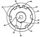
图5是沿图1中胶囊式微型机器人移动系统的组件的线V-V剖取的截面图;Fig. 5 is a sectional view taken along the line V-V of the assembly of the capsule micro-robot moving system in Fig. 1;
图6A至6G是说明图1中胶囊式微型机器人移动系统的移动的示意图;6A to 6G are schematic diagrams illustrating the movement of the capsule microrobot moving system in FIG. 1;
图7是说明根据本发明另一优选实施方式的胶囊式微型机器人移动系统的分解立体图;7 is an exploded perspective view illustrating a capsule microrobot moving system according to another preferred embodiment of the present invention;
图8是沿图7中线VIII-VIII剖取的截面图;Fig. 8 is a sectional view taken along line VIII-VIII in Fig. 7;
图9是说明图7中胶囊式微型机器人移动系统的移动部件的放大分解立体图;Fig. 9 is an enlarged exploded perspective view illustrating moving parts of the capsule microrobot moving system in Fig. 7;
图10是说明胶囊式微型机器人移动系统前进移动的侧视图;Fig. 10 is a side view illustrating the forward movement of the capsule micro-robot moving system;
图11是沿图10中线XI-XI剖取的截面图;Fig. 11 is a sectional view taken along line XI-XI in Fig. 10;
图12是说明胶囊式微型机器人移动系统后退移动的侧视图;Fig. 12 is a side view illustrating the backward movement of the capsule micro-robot moving system;
图13是沿图12中的线XIII-XIII剖取的截面图;Fig. 13 is a sectional view taken along line XIII-XIII in Fig. 12;
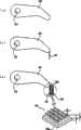
图14A至14C是说明图12中臂的形状的示意图。14A to 14C are schematic diagrams illustrating the shape of the arm in FIG. 12 .
具体实施方式Detailed ways
下面将描述根据本发明优选实施方式的胶囊式微型机器人移动系统。The capsule microrobot movement system according to the preferred embodiment of the present invention will be described below.
如图1至6中所示,根据本发明第一优选实施方式的胶囊式微型机器人移动系统100包括用于移动胶囊的驱动部件110、由驱动部件110沿胶囊的纵向移动的内圆筒120、具有中空部130a以环绕内圆筒120的外圆筒130、用于封闭内圆筒120和外圆筒130的胶囊140、以可旋转方式固定至外圆筒130以根据移动方向而向胶囊140内合拢或向胶囊140外展开的臂150以及设置在胶囊140前部的半球形摄像机160。As shown in Figures 1 to 6, the capsule-type microrobot moving system 100 according to the first preferred embodiment of the present invention includes a driving
驱动部件110包括:安装在胶囊140尾部的超小型马达111;以及与超小型马达111的旋转轴相关联而旋转的螺杆112。超小型马达111通过电池驱动。The
内圆筒120具有形成在与驱动部件110的螺杆112紧固在一起的中心穿孔部分内的螺纹121,以及沿圆周方向形成在内圆筒的外圆周中部的锁定槽122。锁定槽122提供用于容纳臂150的部件的空间,如图3和4中所示,根据内圆筒120的移动,由于与臂150的作用,臂150绕线159旋转而合拢或展开。此外,如图3和4中所示,锁定槽122凹陷以形成竖直的壁122a和122b,使得其底部平整。The
外圆筒130具有:槽131,其沿臂150的旋转方向(沿外圆筒的纵向)形成在外圆筒130的外圆周上,使得臂150能够旋转预设的角度;以及铰接凹部132,其沿圆周方向连续地(in series)形成在外圆周上,以设置穿过铰接孔151的线159。形成穿过槽131内侧的第一暴露孔133a,使得臂150的部件容纳在内圆筒120的锁定槽122内。The
胶囊140用作机器人的本体并且具有外表面,所述外表面涂敷有用于减小运动时与器官的摩擦的防附着涂剂,使得胶囊140在器官内能够快速地移动,并且第二暴露孔141沿纵向长地形成在胶囊140的外圆周上,使得胶囊140能够在臂150直接接触并粘至器官的壁之后移动。胶囊140的前部形成有用于安装摄像机160的开口142。The
在此,第二暴露孔141与臂150对齐,并且因为如图1中所示在外圆筒130上安装有六个臂,所以第二暴露孔141的个数也为六个。Here, the second exposure holes 141 are aligned with the
六个臂150每隔60度地形成在外圆筒130的圆周上,从而以更多的接触点粘至器官的壁。这样,能够有效地保证器官10和臂150之间的摩擦。优选地,在臂150与器官10的壁接触的端部,为了获取大的摩擦,形成有多个微小的凸起153。Six
在此,通过将单线159穿过臂150的铰接孔151、臂150的部件插进第一暴露孔133a并且线159置于铰接凹部132上,实现了将臂150固定至外圆筒130而进行旋转。如图3和5中所示,插进第一暴露孔133a的臂150的部件容纳在安装在外圆筒130的中部的内圆筒120的锁定槽内。这样,臂150安装在外圆筒130的槽131内以进行旋转。当内圆筒120沿胶囊140的纵向移动时,臂150的插入部分与内圆筒120的锁定槽122作用,使得臂150根据内圆筒120的移动方向合拢或展开。Here, by passing a
在如上所述本发明第一优选实施方式中,当螺杆112通过马达111旋转时,内圆筒120必须沿胶囊140的纵向移动。为此,因为必需抑制内圆筒120的旋转,如图5中所示,旋转防止凸部123形成在内圆筒120的外圆周上,并且旋转防止凹部135沿纵向形成在外圆筒130的整个内圆周上以与旋转防止凸部123接合。从而,内圆筒120沿纵向抵靠外圆筒130线性地移动,而抑制了旋转。In the first preferred embodiment of the present invention as described above, when the
类似地,在胶囊140内抑制外圆筒130的旋转。这种设计是为了防止外圆筒130和内圆筒120一起旋转,以及为了将安装至外圆筒130的臂150设置在胶囊140的第二暴露孔141之间。为此,胶囊140具有形成在胶囊140内圆周上的凸部141b,并且外圆筒130具有形成在外圆筒130的外圆周的纵向上的槽134以与凸部141b接合。Similarly, rotation of the
根据本发明第一优选实施方式的胶囊式微型机器人移动系统按照如下步骤组装。The capsule micro robot moving system according to the first preferred embodiment of the present invention is assembled according to the following steps.
首先,将马达11与螺杆112耦连以形成驱动部件110。其次,通过螺钉将螺杆112与内圆筒120耦连,并且外圆筒130环绕内圆筒120。在此状态下,在线159穿过六个臂150的铰接孔151以将它们互相连接之后,将各个臂150插进穿过外圆筒130外圆周的第一暴露孔133a的位置中,并且约束住线159的自由端,将线159插进铰接凹部132内并置于其中。此时,因为臂150的部件穿过外圆筒130,并且容纳在内圆筒120的锁定槽122的空间内,在将臂150固定至外圆筒130后,内圆筒120便不会从外圆筒130分离。First, the motor 11 is coupled with the
之后,为了将外圆筒130的槽134与胶囊140内圆周的凸部141b接合,内圆筒120、外圆筒130和驱动部件110形成的组件被插进并固定至胶囊140。在将组件插进胶囊140的状态下,因为外圆筒130的第一暴露孔133a与胶囊140的第二暴露孔141对齐,所以展开的臂150穿过暴露孔133a和141,并且暴露在胶囊140上。Thereafter, an assembly formed by the
其次,摄像机160固定至胶囊140的前端。根据本发明第一优选实施方式的胶囊式微型机器人移动系统100组装完毕。Second, the
下面将描述根据本发明第一优选实施方式的胶囊式微型机器人移动系统的操作原理。The operating principle of the capsule micro robot moving system according to the first preferred embodiment of the present invention will be described below.
当驱动部件110的螺杆112沿预定的方向旋转时,如图3中所示,内圆筒120沿下降方向d1向下移动,内圆筒120的锁定槽122的上壁122b下压臂150,使得臂150沿图中示为a1的方向展开。When the
当驱动部件110的螺杆112沿相反的方向旋转时,如图4中所示,内圆筒120沿上升方向d2向上移动,内圆筒120的锁定槽122的下壁122a上压臂150,使得臂150沿图中示为a2的方向展开。When the
下面,根据上述原理,将描述根据本发明第一优选实施方式的胶囊式微型机器人移动系统100在器官10的壁上移动的原理。Next, based on the above principles, the principle of the movement of the capsule microrobot moving system 100 on the wall of the organ 10 according to the first preferred embodiment of the present invention will be described.
图6A示出展开的臂150。在图6A所示的状态下,当螺杆112沿预定的方向旋转时,根据图3中所示的原理,内圆筒120沿下降方向d1向下移动,并且臂150旋转(a1)出胶囊140外,进而展开(参见图6B)。当螺杆112进一步沿预定的方向旋转时,因为臂150暴露在器官10的壁上并且保持器官10的壁,臂150和外圆筒130保持停止在器官壁上,并且内圆筒120靠近驱动部件110。换言之,图6B中所述的状态改变至图6D所述的状态,并且胶囊相对地前进。FIG. 6A shows the
在参照图6D的胶囊移动得尽可能最多的状态下,当螺杆112沿相反的方向旋转时,根据图4中的原理,内圆筒120沿上升方向d2向上移动并且臂150向胶囊140内旋转(a2)并且向胶囊140内合拢。当螺杆112进一步沿此相反的方向旋转时,因为臂150不接触器官10的壁,胶囊140保持停止在器官10的壁上,并且驱动部件110和内圆筒120之间的距离较远,达到如图6G中的状态。换言之,图6G中的状态与图6A中的状态相同,但是胶囊140前进了图6A中的参考标记x所示的距离。In the state where the capsule moves as much as possible with reference to FIG. 6D , when the
重复图6A至6G中的过程,使得根据本发明第一优选实施方式的胶囊式微型机器人向前移动。The process in FIGS. 6A to 6G is repeated, so that the capsule microrobot according to the first preferred embodiment of the present invention moves forward.
期间,虽然在第一优选实施方式中驱动部件包括超小型马达111,并且螺杆112与马达111相关联而旋转,但是可以使用例如PZT直线超声马达的多种线性驱动器。虽然为了抑制内圆筒120和外圆筒130之间的相对旋转位移,形成了彼此接合的凹部135和凸部123,但是,即使改为形成有固定的导向杆(未图示)以横过内圆筒120的纵向,也能实现相同的效果。Meanwhile, although the drive means includes the ultra-small motor 111 and the
另外,根据本发明第一优选实施方式的胶囊式微型机器人移动系统仅前进移动,在本发明另一优选实施方式中,提供了一种能够前后移动的胶囊式微型机器人移动系统。In addition, the capsule microrobot moving system according to the first preferred embodiment of the present invention only moves forward, and in another preferred embodiment of the present invention, a capsule microrobot moving system capable of moving back and forth is provided.
在本发明另一优选实施方式的描述中,为了清楚地描述,相同的参考标记用于与本发明第一优选实施方式相同或类似的部件上,并且略去了其描述。In the description of another preferred embodiment of the present invention, for clarity of description, the same reference numerals are used for the same or similar parts as those of the first preferred embodiment of the present invention, and descriptions thereof are omitted.
如图7中所示,根据本发明另一优选实施方式的胶囊式微型机器人移动系统100’包括用于移动胶囊的驱动部件110、沿胶囊纵向移动的内圆筒120’、形成有中空部130a以环绕内圆筒120’的外圆筒130’、用于封闭内圆筒120’和外圆筒130’的胶囊140、以可旋转方式固定至外圆筒130’以根据移动方向而向胶囊140内合拢或向胶囊140外展开的臂150和150’以及设置在胶囊140前部的半球形摄像机160。As shown in FIG. 7, a capsule-type microrobot moving system 100' according to another preferred embodiment of the present invention includes a driving
内圆筒120’具有:形成在中央穿孔部分中的螺纹121’,所述中央穿孔部分与驱动部件110的螺杆112固定在一起;以及锁定槽122’,其沿圆周方向形成在其外圆周的中部。锁定槽122’侧面上的侧凸部126’每隔120度形成有径向凸出的锁定凸部125’,并且在126’之间没有凸部。由于此构型,当内圆筒120’移动时,间隔安装的臂150和150’中的一组与锁定凸部125’作用,而另一组不管内圆筒120’如何移动都不与锁定凸部125’作用。The inner cylinder 120' has: a thread 121' formed in a central perforated portion fixed with the
外圆筒130’具有第一暴露孔133a,其穿过槽131的内侧并且以等间隔沿圆周方向形成,使得臂150的部件容纳在内圆筒120’的锁定槽122内。The outer cylinder 130' has
在此,为了使间隔安装的臂150和150’中的一组相互作用,加入了图8的放大图中所示的结构。换言之,在内圆筒120’的锁定凸部125’的任意外圆周上,凹部123a’和123b’在对应于臂150和150’之间距离的60度处形成,并且在形成于外圆筒130’的内圆周上的凹部135’中,安装有插设在凹部123a’和123b’其中一个内的T形销137’和由形状记忆合金(SMA)制成用以致动所述销137’的致动器136’。因为SMA致动器136’被施加以电流,当施加电流后,致动器136’收缩,使得销137’的端部从凹部123a’出来,并且此时驱动部件110的马达旋转,使得能够实现内圆筒120’和外圆筒130’之间的相对旋转。然后,当外圆筒130’相对于内圆筒120’旋转60度时,固定至外圆筒130’的销137’的端部插进凹部123b’,使得内圆筒120’和外圆筒130’之间的相对运动受到抑制。Here, in order to allow a set of spaced apart
胶囊140用作机器人的本体,并且具有涂敷有用于减小运动时与器官的摩擦的防附着涂剂的外表面,使得胶囊140能够在器官内快速地移动,并且第二暴露孔141沿纵向长地形成在胶囊140的外圆周上,使得在臂150和150’直接接触并粘至器官壁后胶囊140能够移动。The
如图9中所示,六个臂150沿外圆筒130’的外圆周方向以60度间隔交替安装。As shown in FIG. 9, six
期间,如图14A中所示,优选地,臂150的端部倒圆以防止器官壁受到破坏。然而,为了维持用于前后运动的驱动力,壁150优选地由刚体制成。期间,如图14B中所示,为了更牢固地夹紧器官壁,更优选地,臂150的端部安装有抵着臂150平滑地弯曲的弹性体或柔性接头152。另外,如图14C中所示,具有高附着力的附着板153可以附连至臂150的接触器官壁的端部或柔性接头152。在此,附着板153具有与晰蜴的脚底中的纤毛类似的结构,并且例如,每个纤毛具有约几百nm至几μm的直径d,以及约几μm至几十μm的高度h,且其以微小或极小的形式形成,并且附着板153的底部153a可以由柔性材料制成以具有约0.5mm的厚度。换言之,根据用途,纤毛的直径d与高度h的比率能够设置成在约1∶1至1∶100的范围内。附着板153的结构披露于名称为“附着微结构及其形成方法(Adhesive microstructure and method of forming same)”的美国专利No.6,737,160B1中。Meanwhile, as shown in Fig. 14A, the ends of the
如上所述结构的本发明优选实施方式100’的操作原理类似于第一优选实施方式100。更具体地,如图10和11中所示,在仅仅向后弯曲的臂150的组与内圆筒120’的锁定凸部125’作用的状态下,当内圆筒120’移动时,尽管内圆筒120’移动,但向前弯曲的臂150’也不能展开至胶囊140外,但是,由于内圆筒120’的凸部125’的作用,向后弯曲的臂150的组穿过胶囊140的第二暴露孔141重复合拢和展开,进而前进。The operating principle of the preferred embodiment 100' of the present invention structured as described above is similar to that of the first preferred embodiment 100. More specifically, as shown in FIGS. 10 and 11 , in a state where only the group of
为了根据使用目的和/或按需要向后移动胶囊式微型机器人移动系统100’,当预设的电流被施加至外圆筒130’的致动器136’时,由SMA制成的致动器136’收缩,使得固定至致动器136端部的销137’从形成于内圆筒120’上的凹部123a出来。然后,当驱动部件110的马达旋转时,因为内圆筒120’和外圆筒130’之间的关联被放开,所以仅内圆筒120’关于外圆筒130相对旋转。当驱动部件110的马达被控制成旋转约60度并且同时施加至致动器136’的电流被中断时,销137插设进与其隔开60度的另一凹部123b’中,仅向后朝向的臂150’与内圆筒120’的锁定凸部125’作用,而向前朝向的臂150不再与锁定凸部125’作用。换言之,实现了内圆筒120’和外圆筒130’一起旋转的关联。在此状态下,当驱动部件110被驱动以移动内圆筒120’时,类似于第一优选实施方式的原理,能够实现向后的运动。从而,胶囊能够根据需要前后移动。In order to move the capsule micro-robot moving system 100' backward according to the purpose of use and/or as needed, when a preset current is applied to the actuator 136' of the outer cylinder 130', the actuator made of SMA 136' shrinks so that a pin 137' fixed to the end of the
同时,虽然在此优选实施方式100’中臂150和150’分别是六个,但是如果需要的话,可以使用更多数量的臂150和150’以在器官壁上保持和移动。Also, although there are six
虽然只示出和描述了本发明的若干几个实施方式,但是可以理解,所属技术领域技术人员在不背离范围由权利要求及其等价同物限定的本发明的原理和精神的情况下此实施方式可以作出改变。Although only a few embodiments of the present invention have been shown and described, it should be understood that those skilled in the art can do so without departing from the principle and spirit of the present invention whose scope is defined by the claims and their equivalents. Embodiments may vary.
本发明提供了一种胶囊式微型机器人移动系统,其能够以较高的速度移动穿过粘滞的内部器官。The present invention provides a capsule microrobot locomotion system capable of moving through viscous internal organs at high speeds.
Claims (25)
Translated fromChineseApplications Claiming Priority (4)
| Application Number | Priority Date | Filing Date | Title |
|---|---|---|---|
| KR1020050039884AKR100702155B1 (en) | 2005-05-12 | 2005-05-12 | Encapsulated Micro Robot Drive System |
| KR1020050039884 | 2005-05-12 | ||
| KR10-2005-0039884 | 2005-05-12 | ||
| PCT/KR2005/004266WO2006121239A1 (en) | 2005-05-12 | 2005-12-13 | Capsule type micro-robot moving system |
Publications (2)
| Publication Number | Publication Date |
|---|---|
| CN101188964A CN101188964A (en) | 2008-05-28 |
| CN101188964Btrue CN101188964B (en) | 2010-06-16 |
Family
ID=37396718
Family Applications (1)
| Application Number | Title | Priority Date | Filing Date |
|---|---|---|---|
| CN2005800499610AActiveCN101188964B (en) | 2005-05-12 | 2005-12-13 | Capsule type micro-robot moving system |
Country Status (6)
| Country | Link |
|---|---|
| US (1) | US7365509B2 (en) |
| EP (1) | EP1885231B1 (en) |
| JP (1) | JP4660590B2 (en) |
| KR (1) | KR100702155B1 (en) |
| CN (1) | CN101188964B (en) |
| WO (1) | WO2006121239A1 (en) |
Families Citing this family (68)
| Publication number | Priority date | Publication date | Assignee | Title |
|---|---|---|---|---|
| US7655001B2 (en)* | 2001-03-23 | 2010-02-02 | Petrakis Dennis N | Temperature responsive systems |
| US7998060B2 (en)* | 2004-04-19 | 2011-08-16 | The Invention Science Fund I, Llc | Lumen-traveling delivery device |
| US9011329B2 (en) | 2004-04-19 | 2015-04-21 | Searete Llc | Lumenally-active device |
| US8024036B2 (en)* | 2007-03-19 | 2011-09-20 | The Invention Science Fund I, Llc | Lumen-traveling biological interface device and method of use |
| US8337482B2 (en)* | 2004-04-19 | 2012-12-25 | The Invention Science Fund I, Llc | System for perfusion management |
| US8000784B2 (en) | 2004-04-19 | 2011-08-16 | The Invention Science Fund I, Llc | Lumen-traveling device |
| US8092549B2 (en) | 2004-09-24 | 2012-01-10 | The Invention Science Fund I, Llc | Ciliated stent-like-system |
| US8512219B2 (en) | 2004-04-19 | 2013-08-20 | The Invention Science Fund I, Llc | Bioelectromagnetic interface system |
| US8361013B2 (en)* | 2004-04-19 | 2013-01-29 | The Invention Science Fund I, Llc | Telescoping perfusion management system |
| US8353896B2 (en) | 2004-04-19 | 2013-01-15 | The Invention Science Fund I, Llc | Controllable release nasal system |
| US7850676B2 (en)* | 2004-04-19 | 2010-12-14 | The Invention Science Fund I, Llc | System with a reservoir for perfusion management |
| US20120035540A1 (en) | 2006-04-12 | 2012-02-09 | Searete Llc, A Limited Liability Corporation Of The State Of Delaware | Event-based control of a lumen traveling device |
| RU2008141608A (en)* | 2006-04-21 | 2010-05-27 | Физули Акбер оглы Насиров (AZ) | CONTROLLED ROBOT ENDOSCOPE OF MICROCapsule TYPE |
| US20100113874A1 (en) | 2007-04-04 | 2010-05-06 | Marco Quirini | Teleoperated endoscopic capsule |
| JP5410008B2 (en)* | 2007-07-13 | 2014-02-05 | 敏文 早川 | Endoscopy propulsion device |
| JP2009045141A (en)* | 2007-08-16 | 2009-03-05 | Fujifilm Corp | Endoscope insertion aid and endoscope |
| US20090088618A1 (en) | 2007-10-01 | 2009-04-02 | Arneson Michael R | System and Method for Manufacturing a Swallowable Sensor Device |
| WO2009063377A1 (en)* | 2007-11-13 | 2009-05-22 | Koninklijke Philips Electronics N.V. | Ingestible electronic capsule |
| CN101242047B (en) | 2008-02-26 | 2010-06-09 | 华为终端有限公司 | USB connecting piece and USB device |
| KR100999657B1 (en) | 2008-08-04 | 2010-12-08 | 전남대학교산학협력단 | Maintenance and movement system of micro robot for vascular treatment |
| KR100996487B1 (en) | 2008-11-10 | 2010-11-24 | 연세대학교 산학협력단 | In vivo mobile robot moved by expansion and contraction and its driving method |
| CN101659054B (en)* | 2009-09-09 | 2011-04-27 | 大连理工大学 | A capsule robot and its multi-wedge effect driving control method |
| KR101074511B1 (en)* | 2009-11-13 | 2011-10-17 | 한국과학기술연구원 | Capsule type micro-robot bidirectioanl moving system |
| KR101135597B1 (en) | 2010-03-05 | 2012-04-17 | 한국과학기술연구원 | Bidirectioanl moving micro-robot system |
| KR101070275B1 (en) | 2010-03-05 | 2011-10-06 | 한국과학기술연구원 | End Sturcture for Minimizing Tissue Damage by Contacting Intenal Organs |
| CN102048517B (en)* | 2011-01-05 | 2012-05-30 | 华南理工大学 | Screw-type active-thrust capsule-like robot |
| US20130137921A1 (en)* | 2011-11-28 | 2013-05-30 | Industrial Technology Research Institute | Propelling system and capsule applying the same |
| GB2497544A (en)* | 2011-12-13 | 2013-06-19 | Staffordshire University Entpr And Commercial Dev | Travelling capsule with two drive mechanisms |
| CN102512243B (en)* | 2012-01-11 | 2013-12-11 | 金枫 | Micro operating knife |
| CN102862617A (en)* | 2012-07-02 | 2013-01-09 | 上海大学 | Head drawing mechanism of ruin slit searching and rescuing robot |
| CN103117606B (en)* | 2013-03-05 | 2016-02-17 | 上海交通大学 | For the micro electromagnetic actuator of gastrointestinal robot |
| CN103211564B (en)* | 2013-04-22 | 2015-06-24 | 上海交通大学 | Microrobot for gastrointestinal tract |
| KR101510196B1 (en) | 2013-10-10 | 2015-04-09 | 한국과학기술연구원 | Motion control system for module type capsule robot in body |
| CN103598868B (en)* | 2013-11-01 | 2015-11-04 | 陈宏涛 | A kind of Wheel-claw type endoscope robot |
| CN103691048B (en)* | 2013-12-31 | 2015-09-23 | 山东科技大学 | A kind of micro device acting on target cell |
| CN104165621B (en)* | 2014-08-12 | 2016-04-20 | 四川准达科技有限责任公司 | Borehole camera deviational survey robot |
| CN104287685B (en)* | 2014-10-08 | 2016-03-02 | 南京航空航天大学 | Parked and the pose adjusting device of elastic rod guide type capsule endoscope robot and method |
| CZ28212U1 (en) | 2014-12-01 | 2015-05-19 | Vysoká škola báňská- Technická univerzita Ostrava | Device comprising autonomous system providing analysis and flow of bulk material |
| CN106137760B (en)* | 2015-03-26 | 2019-12-13 | 上海安翰医疗技术有限公司 | Capsule-shaped shell and preparation method, capsule endoscope having the capsule-shaped shell |
| US10675755B2 (en)* | 2015-04-27 | 2020-06-09 | Fondazione Istituto Italiano Di Tecnologia | Shape-keeping deployable structure including a pair of robotic systems of the continuum type |
| JP7082052B2 (en) | 2015-09-03 | 2022-06-07 | ネプチューン メディカル インク. | A device for advancing the endoscope in the small intestine |
| CN105395160B (en)* | 2015-12-15 | 2019-02-26 | 中科院合肥技术创新工程院 | A Capsule Endoscope with Precise Positioning Function |
| CN105395155B (en)* | 2015-12-15 | 2019-02-26 | 中科院合肥技术创新工程院 | A Capsule Endoscope with Positioning Function |
| EP3500151A4 (en) | 2016-08-18 | 2020-03-25 | Neptune Medical Inc. | DEVICE AND METHOD FOR IMPROVED VISUALIZATION OF THE SMALL BOWEL |
| CN106419820A (en)* | 2016-09-26 | 2017-02-22 | 江阴市人民医院 | Surgical instrument for thoracoscope |
| CN106986264B (en)* | 2017-05-19 | 2018-08-17 | 福州大学 | A kind of tubular article Filtting device |
| JP7379321B2 (en) | 2017-07-20 | 2023-11-14 | ネプチューン メディカル インク. | Dynamically rigid overtube |
| CN107960976B (en)* | 2017-11-22 | 2019-09-24 | 上海交通大学 | The axial drive means of the noninvasive diagnosis and treatment microrobot of enterogastric diseases |
| CN107854107A (en)* | 2017-12-26 | 2018-03-30 | 张佳凤 | A kind of hypodynia clinic Gastrointestinal Endoscopes |
| CN108852261B (en)* | 2018-05-04 | 2020-07-24 | 哈尔滨工业大学深圳研究生院 | Oar type active leg stretching and contracting device-based endoscope robot |
| US12059128B2 (en) | 2018-05-31 | 2024-08-13 | Neptune Medical Inc. | Device and method for enhanced visualization of the small intestine |
| CN112714658A (en) | 2018-07-19 | 2021-04-27 | 海王星医疗公司 | Dynamic rigidized composite medical structure |
| WO2020046979A1 (en)* | 2018-08-27 | 2020-03-05 | Drive Medical, Inc. | Devices and systems for body cavities and methods of use |
| CN109223099B (en)* | 2018-08-28 | 2020-04-28 | 上海大学 | A multimodal vascular robot based on giant electrorheological fluid |
| WO2020214221A1 (en) | 2019-04-17 | 2020-10-22 | Neptune Medical Inc. | Dynamically rigidizing composite medical structures |
| US11793392B2 (en) | 2019-04-17 | 2023-10-24 | Neptune Medical Inc. | External working channels |
| CN112220525A (en)* | 2019-07-15 | 2021-01-15 | 彭志军 | Ultrasonic dredging robot device capable of freely moving in blood vessel from front to back |
| DE102020100519A1 (en)* | 2020-01-13 | 2021-07-15 | OilQuick Deutschland KG | Loading crane changer |
| CA3169052A1 (en)* | 2020-02-26 | 2021-09-02 | Drive Medical, Inc. | Devices and systems for body cavities and methods of use |
| CA3178444A1 (en) | 2020-03-30 | 2021-10-07 | Neptune Medical Inc. | Layered walls for rigidizing devices |
| CN112773305B (en)* | 2021-01-28 | 2023-05-16 | 华中科技大学同济医学院附属协和医院 | Capsule gastroscope and power supply screw mechanism thereof |
| CN114795077B (en)* | 2021-01-29 | 2024-09-24 | 上海交通大学 | Inchworm-like flexion and extension micro-intestinal robot mechanism |
| KR20230133374A (en) | 2021-01-29 | 2023-09-19 | 넵튠 메디컬 인코포레이티드 | Device and method for preventing inadvertent movement of a dynamic stiffening device |
| KR102625668B1 (en) | 2021-07-07 | 2024-01-18 | 성신여자대학교 연구 산학협력단 | A capsule endoscope apparatus and supporting methods for diagnosing the lesions |
| CN114271874B (en)* | 2021-12-23 | 2023-12-29 | 浙江大学 | Magnetically-driven capsule robot |
| KR20250003955A (en) | 2022-04-27 | 2025-01-07 | 넵튠 메디컬 인코포레이티드 | Sanitary outer covering for endoscope |
| US12330292B2 (en) | 2023-09-28 | 2025-06-17 | Neptune Medical Inc. | Telescoping robot |
| CN118177698B (en)* | 2024-02-29 | 2025-09-19 | 南方科技大学 | Capsule robot and capsule robot system |
Citations (1)
| Publication number | Priority date | Publication date | Assignee | Title |
|---|---|---|---|---|
| CN1572228A (en)* | 2003-05-22 | 2005-02-02 | 西门子公司 | Endoscope device |
Family Cites Families (20)
| Publication number | Priority date | Publication date | Assignee | Title |
|---|---|---|---|---|
| JPS5479986A (en)* | 1977-12-08 | 1979-06-26 | Hattori Norikazu | Device for towing cavity mirror |
| JPH04144533A (en)* | 1990-10-05 | 1992-05-19 | Olympus Optical Co Ltd | Endoscope |
| JPH05344951A (en)* | 1992-06-16 | 1993-12-27 | Toshiba Corp | Imaging device and driving device thereof |
| US5662587A (en)* | 1992-09-16 | 1997-09-02 | Cedars Sinai Medical Center | Robotic endoscopy |
| US5337732A (en)* | 1992-09-16 | 1994-08-16 | Cedars-Sinai Medical Center | Robotic endoscopy |
| US6240312B1 (en)* | 1997-10-23 | 2001-05-29 | Robert R. Alfano | Remote-controllable, micro-scale device for use in in vivo medical diagnosis and/or treatment |
| US6737160B1 (en) | 1999-12-20 | 2004-05-18 | The Regents Of The University Of California | Adhesive microstructure and method of forming same |
| KR100486702B1 (en)* | 2000-07-25 | 2005-05-03 | 삼성전자주식회사 | Micro robot |
| KR100437262B1 (en)* | 2000-10-05 | 2004-06-23 | 한국과학기술원 | Smart Capsule Moving Unit for Intestines Examination |
| JP2002187100A (en)* | 2000-12-20 | 2002-07-02 | Japan Science & Technology Corp | Micromachine movable in a living body and control system therefor |
| KR100426613B1 (en) | 2001-05-19 | 2004-04-08 | 한국과학기술연구원 | Micro robot driving system |
| KR100402920B1 (en)* | 2001-05-19 | 2003-10-22 | 한국과학기술연구원 | Micro robot |
| KR100390860B1 (en)* | 2001-09-14 | 2003-07-12 | 한국과학기술원 | Moving Merchine of An Endoscope for Inspecting Large Intestine |
| US20030125788A1 (en)* | 2001-11-09 | 2003-07-03 | Long Gary L. | Self-propelled, intraluminal device with electrode configuration and method of use |
| KR100417163B1 (en)* | 2001-11-12 | 2004-02-05 | 한국과학기술연구원 | Micro capsule robot |
| KR100482275B1 (en)* | 2002-08-09 | 2005-04-13 | 한국과학기술연구원 | Micro capsule robot |
| KR20040055293A (en)* | 2002-12-20 | 2004-06-26 | 김대은 | The Method and Device of Position Movement Control of Microcapsule-type Endoscope by Diameter Expansion Mechanism |
| KR20040102927A (en)* | 2003-05-30 | 2004-12-08 | 정병태 | A capsule and capsule type endoscope provided with a movement fuction |
| JP2004073887A (en)* | 2003-11-12 | 2004-03-11 | Olympus Corp | Capsule endoscope |
| ITPI20040008A1 (en)* | 2004-02-17 | 2004-05-17 | Dino Accoto | ROBOTIC CAPSULE FOR INTRA-BODY BIOMEDICAL APPLICATIONS |
- 2005
- 2005-05-12KRKR1020050039884Apatent/KR100702155B1/ennot_activeExpired - Fee Related
- 2005-12-13JPJP2008511039Apatent/JP4660590B2/ennot_activeExpired - Fee Related
- 2005-12-13CNCN2005800499610Apatent/CN101188964B/enactiveActive
- 2005-12-13WOPCT/KR2005/004266patent/WO2006121239A1/enactiveApplication Filing
- 2005-12-13EPEP05822018Apatent/EP1885231B1/enactiveActive
- 2006
- 2006-05-10USUS11/431,354patent/US7365509B2/enactiveActive
Patent Citations (1)
| Publication number | Priority date | Publication date | Assignee | Title |
|---|---|---|---|---|
| CN1572228A (en)* | 2003-05-22 | 2005-02-02 | 西门子公司 | Endoscope device |
Also Published As
| Publication number | Publication date |
|---|---|
| EP1885231A4 (en) | 2011-03-16 |
| KR20060117110A (en) | 2006-11-16 |
| JP2008539936A (en) | 2008-11-20 |
| CN101188964A (en) | 2008-05-28 |
| EP1885231B1 (en) | 2012-04-25 |
| JP4660590B2 (en) | 2011-03-30 |
| EP1885231A1 (en) | 2008-02-13 |
| US7365509B2 (en) | 2008-04-29 |
| US20060257234A1 (en) | 2006-11-16 |
| WO2006121239A1 (en) | 2006-11-16 |
| KR100702155B1 (en) | 2007-04-02 |
Similar Documents
| Publication | Publication Date | Title |
|---|---|---|
| CN101188964B (en) | Capsule type micro-robot moving system | |
| CN111658152B (en) | A surgical robotic arm and endoscope system | |
| KR101510196B1 (en) | Motion control system for module type capsule robot in body | |
| KR100482275B1 (en) | Micro capsule robot | |
| JP4541559B2 (en) | Propulsion of an intracolonic probe using a flexible sleeve | |
| US10251540B2 (en) | Apparatus and method for fixing and shortening bowel at the time of endoscopy | |
| JP4611320B2 (en) | Remotely controlled endoscope capsule with mobile motion system | |
| WO2007128084A2 (en) | The controllable microcapsule type robot-endoscope | |
| US8322469B2 (en) | Bidirectional moving micro-robot system | |
| EP2163206A1 (en) | Surgical clip delivering wireless capsule | |
| US20060189844A1 (en) | Endoscopic devide | |
| JP4961898B2 (en) | Capsule medical device | |
| EP2498664B1 (en) | Capsule type micro-robot bidirectional moving system | |
| WO2018082196A1 (en) | Endoscope sleeve cylinder | |
| CN113476117A (en) | Puncture cannula with panoramic image function | |
| Wang et al. | A locomotion mechanism with external magnetic guidance for active capsule endoscope | |
| KR102388737B1 (en) | Capsule Endoscope | |
| CN215584080U (en) | Multi-point observation endoscope probe | |
| Park et al. | Capsular locomotive microrobot for gastrointestinal tract | |
| KR100996487B1 (en) | In vivo mobile robot moved by expansion and contraction and its driving method | |
| Ma et al. | Design, simulation and fabrication of the leg of capsule endoscopy | |
| US20180035874A1 (en) | Apparatus and method for fixation to endoscope accessories | |
| CN119791553A (en) | Capsule endoscope |
Legal Events
| Date | Code | Title | Description |
|---|---|---|---|
| C06 | Publication | ||
| PB01 | Publication | ||
| C10 | Entry into substantive examination | ||
| SE01 | Entry into force of request for substantive examination | ||
| C14 | Grant of patent or utility model | ||
| GR01 | Patent grant | ||
| EE01 | Entry into force of recordation of patent licensing contract | Application publication date:20080528 Assignee:Neo Lab Convergence Inc. Assignor:KOREA INSTITUTE OF SCIENCE AND TECHNOLOGY Contract record no.:2016990000142 Denomination of invention:Capsule type micro-robot moving system Granted publication date:20100616 License type:Exclusive License Record date:20160415 | |
| LICC | Enforcement, change and cancellation of record of contracts on the licence for exploitation of a patent or utility model |