Movatterモバイル変換


[0]ホーム

URL:


CN101188189A - Confinement Baffles and Flow Equalizers for Enhanced Magnetic Control of Radial Plasma Distribution - Google Patents

Confinement Baffles and Flow Equalizers for Enhanced Magnetic Control of Radial Plasma Distribution
Download PDF

Info

Publication number
CN101188189A
CN101188189ACNA2007101702533ACN200710170253ACN101188189ACN 101188189 ACN101188189 ACN 101188189ACN A2007101702533 ACNA2007101702533 ACN A2007101702533ACN 200710170253 ACN200710170253 ACN 200710170253ACN 101188189 ACN101188189 ACN 101188189A
Authority
CN
China
Prior art keywords
plasma
chamber
reactor
base
baffle
Prior art date
Legal status (The legal status is an assumption and is not a legal conclusion. Google has not performed a legal analysis and makes no representation as to the accuracy of the status listed.)
Granted
Application number
CNA2007101702533A
Other languages
Chinese (zh)
Other versions
CN100576438C (en
Inventor
马修·L·米勒
丹尼尔·J·霍夫曼
史蒂文·C·香农
迈克尔·库特尼
詹姆斯·卡杜西
安德鲁·尼古因
Current Assignee (The listed assignees may be inaccurate. Google has not performed a legal analysis and makes no representation or warranty as to the accuracy of the list.)
Applied Materials Inc
Original Assignee
Applied Materials Inc
Priority date (The priority date is an assumption and is not a legal conclusion. Google has not performed a legal analysis and makes no representation as to the accuracy of the date listed.)
Filing date
Publication date
Application filed by Applied Materials IncfiledCriticalApplied Materials Inc
Publication of CN101188189ApublicationCriticalpatent/CN101188189A/en
Application grantedgrantedCritical
Publication of CN100576438CpublicationCriticalpatent/CN100576438C/en
Expired - Fee Relatedlegal-statusCriticalCurrent
Anticipated expirationlegal-statusCritical

Links

Images

Classifications

Landscapes

Abstract

Translated fromChinese

本发明公开一种具有等离子体约束和等离子体径向分布性能的等离子体反应器。该反应器包含在腔室中含有侧壁和工件支撑底座并限制底座和侧壁之间的抽吸环的反应器腔室和在抽吸环底部的抽吸口。该反应器进一步包含用于限制气流在轴向方向上通过抽吸环以防止等离子体流到抽吸口。该反应器进一步包含用于补偿由抽吸口的位移引起的在底座上气流图案的不对称性的工具。该反应器进一步包含用于控制具有固有趋势的等离子体分布的工具,以促进边缘高等离子体密度分布。用于限制气流的工具充分降到工件支撑下面,以补偿用于控制等离子体分布的工具的边缘高等离子体分布趋势。

Figure 200710170253

The invention discloses a plasma reactor with plasma confinement and plasma radial distribution performance. The reactor comprises a reactor chamber containing a side wall and a workpiece support base in the chamber and defining a suction ring between the base and the side wall and a suction port at the bottom of the suction ring. The reactor further comprises a suction ring for restricting gas flow in the axial direction through the suction ring to prevent plasma from flowing to the suction port. The reactor further comprises means for compensating the asymmetry of the gas flow pattern on the base caused by the displacement of the suction port. The reactor further comprises means for controlling the plasma distribution which has an inherent tendency to promote edge high plasma density distribution. The tool used to restrict the gas flow is lowered sufficiently below the workpiece support to compensate for the edge high plasma distribution tendency of the tool used to control the plasma distribution.

Figure 200710170253

Description

Translated fromChinese
增强磁控制等离子体径向分布的约束挡板和流动均衡器Confinement Baffles and Flow Equalizers for Enhanced Magnetic Control of Radial Plasma Distribution

本申请要求享有2006年11月15日提交的美国分案申请序号为No.60/859,558的权益。This application claims the benefit of US Divisional Application Serial No. 60/859,558, filed November 15, 2006.

技术领域technical field

本发明的实施方式主要涉及一种用于等离子体高流导轴向约束和流动均衡的方法和装置,该方法和装置通过阻抗约束增强等离子体径向分布的磁控制,并增强等离子体的径向约束Embodiments of the present invention generally relate to a method and apparatus for high conductance axial confinement and flow equalization of plasma, the method and apparatus enhance magnetic control of plasma radial distribution through impedance confinement, and enhance plasma radial constraint

背景技术Background technique

在微电子集成电路的制造中,半导体晶圆的等离子体处理用于介电质蚀刻、金属蚀刻、化学气相沉积和其它工艺中。在半导体衬底处理中,越来越小的部件尺寸和线宽发展的趋势诱使在半导体衬底上掩模、蚀刻和沉积材料具有越来越高的精度。In the fabrication of microelectronic integrated circuits, plasma processing of semiconductor wafers is used in dielectric etch, metal etch, chemical vapor deposition, and other processes. In semiconductor substrate processing, the trend toward ever smaller feature sizes and line widths induces masking, etching, and deposition of materials on semiconductor substrates with ever-increasing precision.

通常,蚀刻通过将射频(RF)功率施加到被供应到在由支撑构件所支撑的衬底上方的低压处理区域的工作气体来完成。所产生的电场在处理区域内生成将工作气体激发为等离子体的反应区域。该支撑构件偏置以吸引朝向在其上支撑的衬底的等离子体。离子朝向邻近衬底的边界层或等离子体鞘迁移并在离开边界层时加速。被加速的离子产生需要从衬底表面去除或蚀刻材料的能量。由于被加速的离子能蚀刻处理腔室内的其它组件,所以将等离子体约束到衬底上方的处理区域且远离腔室的侧壁是很重要的。Typically, etching is accomplished by applying radio frequency (RF) power to a working gas supplied to a low pressure processing region above a substrate supported by a support member. The generated electric field creates a reaction region within the processing region that excites the working gas into a plasma. The support member is biased to attract plasma toward a substrate supported thereon. The ions migrate towards the boundary layer or plasma sheath adjacent to the substrate and are accelerated as they leave the boundary layer. Accelerated ion generation requires energy to remove or etch material from the substrate surface. Since the accelerated ions can etch other components within the processing chamber, it is important to confine the plasma to the processing region above the substrate and away from the sidewalls of the chamber.

无约束的等离子体导致沉积在腔室壁上的蚀刻副产物(通常为聚合物)并同样蚀刻腔室壁。沉积在腔室壁上的蚀刻副产物能使工艺漂移。来自腔室壁的蚀刻材料通过再沉积污染衬底和/或产生腔室中的颗粒。另外,无约束的等离子体还导致沉积在下游区域中的蚀刻副产物。积累的蚀刻副产物剥落并产生颗粒。为了减少由下游区域中蚀刻副产物的沉积引起的颗粒问题,需要额外的后蚀刻(下游)清洗步骤,其将降低工艺产量并增加工艺成本。The unconfined plasma results in etch by-products (usually polymers) that deposit on the chamber walls and also etch the chamber walls. Etch by-products deposited on the chamber walls can cause process drift. Etched material from the chamber walls contaminates the substrate by redeposition and/or creates particles in the chamber. Additionally, the unconfined plasma also leads to etch by-products that are deposited in downstream regions. The accumulated etch by-products flake off and generate particles. In order to reduce particle problems caused by deposition of etch by-products in the downstream region, an additional post-etch (downstream) cleaning step is required, which reduces process throughput and increases process cost.

受约束的等离子体将降低腔室污染、腔室清洗并改善工艺可重复性(或减少工艺漂移)。A confined plasma will reduce chamber contamination, chamber cleaning and improve process repeatability (or reduce process drift).

发明内容Contents of the invention

在本发明的一个方案中,等离子体反应器包含具有腔室侧壁、顶部和底部的腔室。工件支撑底座位于腔室内并包含工件支撑表面。底座侧壁与腔室侧壁相对并从腔室底部延伸。工件支撑底座限定腔室侧壁和底座侧壁之间的抽吸环。抽吸口设置在腔室底部中。环形等离子体约束挡板从底座侧壁延伸,并具有限定在边缘和腔室侧壁之间的气流间隙的外部边缘。该挡板降到工件支撑表面下的一段距离处,该距离对应于在工件支撑底座外围处降低的等离子体离子密度。该反应器进一步包含具有在挡板下并阻挡气流通过抽吸环的阻挡板的气流均衡器。该阻挡板限定在抽吸口附近一侧的最小气流传导和在抽吸口相对一侧上的最大气流传导的晶圆支撑底座周围的偏心开口。阻挡板与腔室侧壁隔开以限定在该阻挡板与腔室侧壁之间的足够长的间隙,从而引起最小气流阻力。In one aspect of the invention, a plasma reactor comprises a chamber having chamber side walls, a top and a bottom. A workpiece support base is located within the chamber and includes a workpiece support surface. The base sidewall is opposite the chamber sidewall and extends from the chamber bottom. The workpiece support base defines a suction ring between the chamber sidewall and the base sidewall. A suction port is provided in the bottom of the chamber. An annular plasma confinement baffle extends from the base sidewall and has an outer edge defining a gas flow gap between the edge and the chamber sidewall. The baffle is lowered below the workpiece support surface a distance corresponding to a reduced plasma ion density at the periphery of the workpiece support base. The reactor further comprises a gas flow equalizer having a baffle plate below the baffle and blocking gas flow through the suction ring. The baffle defines an off-center opening around the wafer support pedestal with minimum airflow conduction on one side adjacent the suction opening and maximum airflow conduction on the opposite side of the suction opening. The baffle plate is spaced from the chamber sidewall to define a gap between the baffle plate and the chamber sidewall that is long enough to induce minimal airflow resistance.

根据另一方案,气流均衡器进一步包含从阻挡板外部边缘朝向挡板延伸的轴向壁;并且所述壁导引气流到偏心开口。According to another aspect, the airflow equalizer further comprises an axial wall extending from the outer edge of the baffle towards the baffle; and said wall directs the airflow to the eccentric opening.

根据又一方案,在挡板和腔室侧壁之间的气流间隙足够小以防止或降低到抽吸环的等离子体的流动。According to yet another aspect, the gas flow gap between the baffle and the chamber sidewall is sufficiently small to prevent or reduce the flow of plasma to the pump ring.

反应器进一步包含磁性等离子体导向装置。该磁性等离子体导向装置具有边缘高等离子体离子密度偏置。选择挡板放置在工件支撑平面下的距离,以将底座边缘处的等离子体密度降低到补偿所述磁性导向装置的边缘高等离子体离子密度偏置的量。The reactor further comprises a magnetic plasma guide. The magnetic plasma guide has a marginal high plasma ion density bias. The distance at which the baffle is placed below the workpiece support plane is selected to reduce the plasma density at the edge of the pedestal by an amount that compensates for the high plasma ion density bias at the edge of the magnetic guide.

附图说明Description of drawings

为了获得并能详细理解本发明的以上概述实施方式,以下将参照附图中示出的其实施方式对以上的概述进行更具体的描述。然而,应该理解,附图仅示出了本发明的典型实施方式,并因此不应考虑为对本发明范围的限制,因为本发明承认其它等效实施方式。In order to obtain and understand in detail the above generalized embodiments of the present invention, a more particular description of the above generalized embodiments will be made hereinafter with reference to the embodiments thereof shown in the accompanying drawings. It is to be understood, however, that the appended drawings illustrate only typical embodiments of this invention and are therefore not to be considered limiting of its scope, for the invention admits to other equally effective embodiments.

图1A是等离子体处理腔室的示意性视图;Figure 1A is a schematic view of a plasma processing chamber;

图1B示出了可在图1A的实施方式中使用的槽形约束环;Figure 1B shows a grooved confinement ring that may be used in the embodiment of Figure 1A;

图2A示出了具有在工艺腔室中的环形等离子体约束环的一个实施方式的等离子体处理腔室的示意性视图;Figure 2A shows a schematic view of a plasma processing chamber with one embodiment of an annular plasma confinement ring in the process chamber;

图2B示出了具有在工艺腔室中的环形等离子体约束环的另一个实施方式的等离子体处理腔室的示意性视图;Figure 2B shows a schematic view of another embodiment of a plasma processing chamber having an annular plasma confinement ring in the process chamber;

图2C示出了等离子体密度比率和腔室压力与缝隙宽度的函数关系的模拟结果;Figure 2C shows simulation results of plasma density ratio and chamber pressure as a function of slit width;

图2D示出了当在环孔和腔室壁之间的缝隙宽度为0.5英寸时等离子体处理腔室中的等离子体密度的模拟结果;Figure 2D shows simulation results of the plasma density in the plasma processing chamber when the gap width between the annulus and the chamber wall is 0.5 inches;

图2E示出当在环孔和腔室壁之间的缝隙宽度为3英寸时等离子体处理腔室中的等离子体密度的模拟结果;FIG. 2E shows simulation results of the plasma density in the plasma processing chamber when the gap width between the annulus and the chamber wall is 3 inches;

图3A和图3B是顶部线圈的磁场的图示,而图3C是相同磁场的空间视图;Figures 3A and 3B are illustrations of the magnetic field of the top coil, while Figure 3C is a spatial view of the same magnetic field;

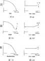
图4A、图4B、图4C和图4D是对于图1A反应器操作的各种模式在晶圆表面上的蚀刻速度(垂直轴)与径向位置(水平轴)的函数关系的视图;4A, 4B, 4C and 4D are graphs of etch rate (vertical axis) on the wafer surface as a function of radial position (horizontal axis) for various modes of operation of the reactor of FIG. 1A;

图5A、图5B、图5C和图5D是图1A反应器操作的进一步模式在晶圆表面上的蚀刻速度(垂直轴)与径向位置(水平轴)的函数关系的视图;5A, 5B, 5C and 5D are graphs of etch rate (vertical axis) on the wafer surface as a function of radial position (horizontal axis) for further modes of operation of the reactor of FIG. 1A;

图6A是图1A的反应器的简要示意性视图,其描述了用于等离子体轴约束的改进的挡板和用于补偿到抽吸口的不均匀气流图案的流动均衡器;Figure 6A is a simplified schematic view of the reactor of Figure 1A depicting improved baffles for plasma axis confinement and flow equalizers to compensate for non-uniform gas flow patterns to the suction port;

图6B是改进挡板的另一实施方式的横截面视图;Figure 6B is a cross-sectional view of another embodiment of an improved baffle;

图6C是改进挡板的再一实施方式的横截面视图;Figure 6C is a cross-sectional view of yet another embodiment of an improved baffle;

图7是示出挡板的1A的反应器的另一横截面平面视图;Figure 7 is another cross-sectional plan view of the reactor of 1A showing baffles;

图8是图1A的反应器的平面横截面视图,其示出了流动均衡器的结构;Figure 8 is a plan cross-sectional view of the reactor of Figure 1A showing the structure of a flow equalizer;

图9A和图9B分别是在磁性增强之前和磁性增强之后用于径向均匀性磁性增强的理想径向蚀刻速度分布的视图;9A and 9B are views of ideal radial etch rate distributions for radially uniform magnetic enhancement before and after magnetic enhancement, respectively;

图10A和图10B分别是在磁性增强之前和磁性增强之后图1A的反应器的典型径向蚀刻速度分布的视图;Figures 10A and 10B are views of typical radial etch rate distributions for the reactor of Figure 1A before and after magnetic enhancement, respectively;

图11A和图11B分别是在磁性增强之前和磁性增强之后具有本发明的改进挡板的图1A的反应器中径向蚀刻速度分布的视图;11A and 11B are views of the radial etch rate distribution in the reactor of FIG. 1A with the improved baffles of the present invention before and after magnetic enhancement, respectively;

图12是比较在晶圆平面下不同高度的挡板在图1A的反应器中所获得的蚀刻速度分布的视图;Fig. 12 is a view comparing the etching rate distribution obtained in the reactor of Fig. 1A by baffles of different heights under the wafer plane;

图13A示出了当电压比率是1(或在顶电极处完全施加源电压)时在顶电极和接地阴极之间的电压;Figure 13A shows the voltage between the top electrode and the grounded cathode when the voltage ratio is 1 (or the source voltage is fully applied at the top electrode);

图13B示出了当电压比率是1(或在顶电极处完全施加源电压)时在顶电极和接地腔室壁之间的电压;Figure 13B shows the voltage between the top electrode and the grounded chamber wall when the voltage ratio is 1 (or the source voltage is fully applied at the top electrode);

图13C示出了当电压比率是0.5(或在顶电极处施加一半源电压)时在顶电极和阴极之间的电压;Figure 13C shows the voltage between the top electrode and the cathode when the voltage ratio is 0.5 (or half the source voltage applied at the top electrode);

图13D示出了当电压比率是0.5(或在顶电极处施加一半源电压)时在顶电极和接地腔室壁之间的电压;Figure 13D shows the voltage between the top electrode and the grounded chamber wall when the voltage ratio is 0.5 (or half the source voltage applied at the top electrode);

图14A示出了模拟等离子体密度比率与电压比率的函数关系;Figure 14A shows simulated plasma density ratio as a function of voltage ratio;

图14B示出了当在环孔和腔室壁之间的缝隙宽度为1.5英寸而电压比率为1时在等离子体处理腔室中等离子体密度的模拟结果;Figure 14B shows the simulation results of the plasma density in the plasma processing chamber when the gap width between the annulus and the chamber wall is 1.5 inches and the voltage ratio is 1;

图14C示出了当在环孔和腔室壁之间的缝隙宽度为1.5英寸而电压比率为0.5时在等离子体处理腔室中等离子体密度的模拟结果;Figure 14C shows the simulation results of the plasma density in the plasma processing chamber when the gap width between the annulus and the chamber wall is 1.5 inches and the voltage ratio is 0.5;

图14D示出了当在环孔和腔室壁之间的缝隙宽度为1.5英寸而电压比率为1时在等离子体处理腔室中的能量沉积的模拟结果;Figure 14D shows simulation results of energy deposition in a plasma processing chamber when the gap width between the annulus and the chamber wall is 1.5 inches and the voltage ratio is 1;

图14E示出了当在环孔和腔室壁之间的缝隙宽度为1.5英寸而电压比率为0.5时在等离子体处理腔室中的能量沉积的模拟结果;Figure 14E shows simulation results of energy deposition in a plasma processing chamber when the gap width between the annulus and the chamber wall is 1.5 inches and the voltage ratio is 0.5;

图15示出了在顶电极、阴极和腔室壁之间的电路图;Figure 15 shows a circuit diagram between the top electrode, the cathode and the chamber wall;

图16是示出用于实施阻抗约束方法的电路的指导模型的简要示意图;Figure 16 is a simplified schematic diagram showing a guiding model of a circuit for implementing the impedance constraint method;

图17是描述其中通过改进挡板增强等离子体的径向阻抗约束程度的方法的视图。FIG. 17 is a view describing a method in which the degree of radial impedance confinement of plasma is enhanced by improving baffles.

为了便于理解,尽可能使用相同的附图标记表示附图中公用的相同元件。附图中的图全是示意性并且没有按照比例绘制。To facilitate understanding, identical reference numerals have been used wherever possible to designate identical elements that are common to the drawings. The figures in the accompanying drawings are all schematic and not drawn to scale.

具体实施方式Detailed ways

本发明的实施方式考虑轴向约束等离子体,以防止等离子体进入晶圆或工件下面的腔室区域,同时补偿到排气口的气流不对称图案。在一个进一步方案中,本发明的实施方式考虑以由磁控制改善径向等离子体分布均匀性的方式完成前述。在另一方案中,本发明的实施方式考虑以通过阻抗约束改善径向等离子体约束的方法完成前述。在等离子体工艺腔室中执行的处理为沉积、蚀刻或等离子体处理。本发明的实施方式可应用到任何类型的等离子体处理,包括等离子体蚀刻工艺、等离子体增强化学气相沉积工艺、物理气相沉积工艺等。Embodiments of the present invention contemplate axially confining the plasma to prevent the plasma from entering the chamber region below the wafer or workpiece while compensating for the asymmetrical pattern of gas flow to the exhaust ports. In a further aspect, embodiments of the present invention contemplate doing the foregoing in a manner that improves radial plasma distribution uniformity by magnetic control. In another aspect, embodiments of the present invention contemplate accomplishing the foregoing by improving radial plasma confinement through impedance confinement. The processing performed in the plasma processing chamber is deposition, etching or plasma processing. Embodiments of the present invention are applicable to any type of plasma processing, including plasma etching processes, plasma enhanced chemical vapor deposition processes, physical vapor deposition processes, and the like.

图1A示出了等离子体反应器的实施例,诸如California的Santa Clara的应用材料有限公司制造的Enabler蚀刻系统,其可包括衬垫以保护壁,在腔室底部具有支撑半导体晶圆110的衬底支架(或底座)105。腔室100包括圆盘形顶部铝电极125,其由电介质(石英)密封130支撑在接地腔体127上的晶圆110上方的预定间隙长度处。处理区域72被限定在顶电极125和衬底支架105之间。功率产生器150施加甚高频(VHF)功率到电极125。VHF通常在约30MHz至约300MHz之间并且其中一个RF带,其在约10kHz到约10GHz之间变化。在一个实施方式中,对于300mm晶圆直径,VHF源功率频率为162MHz。来自产生器150的VHF功率通过匹配到产生器150的同轴电缆162耦合并耦合到与电极125连接的同轴短线(stub)135。短线135具有属性阻抗和短线谐振频率,并提供电极125和同轴电缆162或VHF功率产生器150之间的阻抗匹配。腔体连接到VHF产生器150的VHF回返(return)(VHF接地)。通过经由传统阻抗匹配电路210耦接到晶圆支架105的偏置RF功率产生器200,偏置功率施加到晶圆。偏压产生器200的功率电平控制晶圆表面附近的离子能量。偏置功率(通常在13.56MHz)通常用于控制离子能量,而VHF源功率施加到顶电极以管理等离子体密度。真空泵系统111通过增压室(plenum)112排空腔室100。1A shows an embodiment of a plasma reactor, such as the Enabler(R) etch system manufactured by Applied Materials, Inc. of Santa Clara, California, which may include liners to protect the walls, with a support for asemiconductor wafer 110 at the bottom of the chamber. Substrate holder (or base) 105 . The chamber 100 includes a disc-shapedtop aluminum electrode 125 supported by a dielectric (quartz)seal 130 at a predetermined gap length above thewafer 110 on a groundedchamber 127 . A processing region 72 is defined between thetop electrode 125 and thesubstrate holder 105 . Thepower generator 150 applies very high frequency (VHF) power to theelectrodes 125 . VHF is typically between about 30MHz to about 300MHz and one of the RF bands, which varies between about 10kHz to about 10GHz. In one embodiment, the VHF source power frequency is 162 MHz for a 300 mm wafer diameter. VHF power from thegenerator 150 is coupled through a coaxial cable 162 matched to thegenerator 150 and to acoaxial stub 135 connected to theelectrode 125 . Thestub 135 has a property impedance and a stub resonant frequency, and provides impedance matching between theelectrode 125 and the coaxial cable 162 orVHF power generator 150 . The cavity is connected to the VHF return of the VHF generator 150 (VHF ground). Bias power is applied to the wafer by a biasRF power generator 200 coupled to thewafer holder 105 via a conventionalimpedance matching circuit 210 . The power level of thebias generator 200 controls the ion energy near the wafer surface. Bias power (typically at 13.56MHz) is typically used to control ion energy, while VHF source power is applied to the top electrode to manage plasma density. Avacuum pump system 111 evacuates the chamber 100 through aplenum 112 .

衬底支架105包括支撑下绝缘层5510的金属底座层5505、覆盖下绝缘层5510的导电网格层5515和覆盖导电网格层5515的薄顶绝缘层5520。半导体工件或晶圆110放置在顶绝缘层5520的顶部上。衬底支架105和晶圆110在衬底处理期间形成阴极。如果不存在晶圆110,则在等离子体处理期间衬底支架105是阴极。导电网格层5515和金属底座层5505可分别由诸如钼和铝的材料形成。绝缘层5510和5520可由诸如氮化铝或氧化铝的材料形成。导电网格层5515施加RF偏压以控制晶圆110表面的离子轰击能量。来自RF偏压产生器200的RF功率从偏压阻抗网格210通过在RF馈电点5525a连接到导电网格层5515的RF导体5525输送到导电网格层5515。导电网格层5515还可用于静电夹盘或脱夹盘(de-chuck)晶圆110,并且在情形下可以众所周知的方式连接到夹盘电源。因此导电网格层5515不需要接地并可根据传统的夹盘或脱夹盘操作可选具有浮动电势或固定静电电势。晶圆支架105,特别地金属底座层5505,通常(但不必要)连接到地面,并形成由顶电极125辐射的VHF功率的部分回路。Thesubstrate holder 105 includes ametal base layer 5505 supporting a lower insulatinglayer 5510 , aconductive mesh layer 5515 covering the lower insulatinglayer 5510 , and a thin top insulatinglayer 5520 covering theconductive mesh layer 5515 . A semiconductor workpiece orwafer 110 is placed on top of the top insulatinglayer 5520 . Thesubstrate holder 105 andwafer 110 form a cathode during substrate processing. If nowafer 110 is present, thesubstrate holder 105 is the cathode during plasma processing. Theconductive mesh layer 5515 and themetal pedestal layer 5505 may be formed of materials such as molybdenum and aluminum, respectively. The insulatinglayers 5510 and 5520 may be formed of a material such as aluminum nitride or aluminum oxide. Theconductive mesh layer 5515 applies an RF bias to control the ion bombardment energy on thewafer 110 surface. RF power from theRF bias generator 200 is delivered from thebias impedance grid 210 to theconductive mesh layer 5515 through the RF conductor 5525 connected to theconductive mesh layer 5515 at RF feed point 5525a. Theconductive mesh layer 5515 may also be used to electrostatically chuck or de-chuck thewafer 110, and in that case may be connected to a chuck power supply in a well-known manner. Theconductive mesh layer 5515 therefore does not need to be grounded and can optionally have a floating potential or a fixed electrostatic potential according to conventional chucking or de-chucking operations.Wafer holder 105 , in particularmetal base layer 5505 , is usually (but not necessarily) connected to ground and forms part of the loop for the VHF power radiated bytop electrode 125 .

在一个实施方式中,电介质柱状套5550提供并配置以围绕RF导体5525。利用电介质套5550还增强了衬底之间周围的阻抗均匀性。轴长度和组成套5550的材料的介电常数决定由RF导体5525呈现的到VHF功率的馈点阻抗。通过调整轴长度和组成套5550材料的介电常数,由于VHF源功率的更均匀的电容耦合,可获得更加均匀的阻抗径向分布。In one embodiment, a dielectric cylindrical sleeve 5550 is provided and configured to surround the RF conductor 5525 . Utilizing the dielectric sleeve 5550 also enhances impedance uniformity around the substrate. The shaft length and the dielectric constant of the material making up the sleeve 5550 determine the feed point impedance presented by the RF conductor 5525 to VHF power. By adjusting the shaft length and the dielectric constant of the material making up the sleeve 5550, a more uniform radial distribution of impedance can be obtained due to more uniform capacitive coupling of VHF source power.

在短线135远端135a的终止导体165将内部和外部导体140、145缩短在一起,从而短线135在其远端135a缩短。在短线135的近端135b(未被缩短的端),外部导体145经由环形导电外壳或支架175连接到腔体,而内部导体140经由导电圆柱或支架176连接到电极125的中心。电介质环180固定在导电圆柱176和电极125之间,并与导电圆柱176和电极125分离。A terminating conductor 165 at the distal end 135a of thestub 135 shortens the inner and outer conductors 140, 145 together so that thestub 135 is shortened at its distal end 135a. At proximal end 135b (the non-shortened end) ofstub 135 , outer conductor 145 is connected to the lumen via annular conductive casing or stent 175 , while inner conductor 140 is connected to the center ofelectrode 125 via conductive cylinder or stent 176 . Dielectric ring 180 is fixed between conductive cylinder 176 andelectrode 125 and is separated from conductive cylinder 176 andelectrode 125 .

内部导体140可提供用于诸如工艺气体和冷却剂的管道。该部件的基本优点在于,不同于通常的等离子体反应器,气体管道170和冷却剂管道173不相差大的电势差。因此为了该目的它们可由金属、较不贵且更可靠材料构成。金属性气体管道170在顶电极125中或附近供给气体入口172(从而顶电极125是气体分布板),而金属冷却剂管道173在顶电极125内供给冷却剂通道或套174。The inner conductor 140 may provide conduits for, for example, process gases and coolants. The basic advantage of this component is that, unlike usual plasma reactors, the gas line 170 and the coolant line 173 do not differ by large potential differences. They may therefore consist of metal, a less expensive and more reliable material for this purpose. Metallic gas conduits 170feed gas inlets 172 in or near top electrode 125 (so thattop electrode 125 is a gas distribution plate), while metallic coolant conduits 173 feed coolant channels or sleeves 174 withintop electrode 125 .

如前所述,无约束等离子体使蚀刻副产物(通常为聚合物)沉积在腔室壁上并还能蚀刻腔室壁。沉积在腔室壁上的蚀刻副产物是工艺漂移。来自腔室壁的蚀刻材料通过再沉积污染衬底和/或引起腔室内的颗粒。另外,无约束等离子体还到达处理区域的下游区域并在下游区域中沉积蚀刻副产物,其通常为聚合物。沉积在下游区域中的蚀刻副产物难以清洗。聚积的蚀刻副产物剥落并产生颗粒。As previously mentioned, the unconfined plasma deposits etch by-products (typically polymers) on the chamber walls and also etches the chamber walls. Etching by-products deposited on chamber walls are process drift. Etched material from the chamber walls contaminates the substrate by redeposition and/or causes particles within the chamber. In addition, the unconfined plasma also reaches regions downstream of the processing region and deposits etch by-products, typically polymers, in the downstream regions. Etch by-products deposited in downstream regions are difficult to clean. The accumulated etch by-products flake off and generate particles.

在一个实施方式中,在图1B中示出的槽形约束环可设置并放置在工件支架105周围的图1A的腔室100内部,并在顶电极和衬底支架105之间轴向延伸。槽形约束环可用于减少颗粒污染和腔室的清洗时间。图1B示出了根据一个实施方式的槽形约束环50的透视图。约束环50配置以限定等离子体并减少气体流动阻力。约束环50包括挡板55和耦接到挡板55底部部分的底座58。该底座58一般配置以提供电接地和用于约束环50的机械强度。挡板55在其顶部限定开口71。开口71配置以容纳图1A的顶电极或气体分布板125的喷头,从而气流将被限定在挡板55内部。挡板55进一步包括多个槽57和多个齿59。设计槽57使得等离子体鞘的厚度或宽度大于每个槽的宽度。以这种方式,防止等离子体中的离子和自由基经过约束环50。在一个实施方式中,设计每个槽57具有比等离子体鞘的宽度或厚度小约两倍的宽度。约束环50可由导电材料制成,以当等离子体与约束环50接触时提供RF功率供应和VHF功率供应的接地路径。约束环50还可由导热和耐蚀刻材料制成以最小化局部加热、污染和工艺漂移。例如,挡板55可由碳化硅(SiC)制成,而底座58可由铝(Al)制成。In one embodiment, a grooved confinement ring shown in FIG. 1B may be provided and placed inside the chamber 100 of FIG. 1A around theworkpiece holder 105 and extend axially between the top electrode and thesubstrate holder 105 . Grooved confinement rings can be used to reduce particle contamination and chamber cleaning time. FIG. 1B shows a perspective view of a grooved confinement ring 50 according to one embodiment. Confinement ring 50 is configured to confine the plasma and reduce gas flow resistance. The confinement ring 50 includes a baffle 55 and a base 58 coupled to a bottom portion of the baffle 55 . The base 58 is generally configured to provide electrical grounding and mechanical strength for the confinement ring 50 . The baffle 55 defines an opening 71 at its top. The opening 71 is configured to accommodate the top electrode or showerhead of thegas distribution plate 125 of FIG. 1A so that the gas flow will be confined inside the baffle 55 . The baffle 55 further includes a plurality of slots 57 and a plurality of teeth 59 . The slots 57 are designed so that the thickness or width of the plasma sheath is greater than the width of each slot. In this way, ions and radicals in the plasma are prevented from passing through the confinement ring 50 . In one embodiment, each slot 57 is designed to have a width that is about twice less than the width or thickness of the plasma sheath. The confinement ring 50 may be made of a conductive material to provide a ground path for the RF power supply and the VHF power supply when the plasma is in contact with the confinement ring 50 . The confinement ring 50 can also be made of a thermally conductive and etch resistant material to minimize localized heating, contamination and process drift. For example, the baffle 55 may be made of silicon carbide (SiC), and the base 58 may be made of aluminum (Al).

在一个实施方式中,采用在图1A中示出的平面环孔115。环孔115在与内部腔室侧壁128隔开一距离(或间隙)放置在衬底110周围。环孔115配置并放置在腔室中,从而环孔115提供适当的等离子体约束和低流动阻力。在环孔115的边缘和内部腔室壁128之间的距离(或间隙)不应该过大。如果间隙距离大于腔室壁128附近的等离子体鞘厚度,则它将增加从远离晶圆上方的反应区域并朝向腔室壁和下游抽取的等离子体量,其使等离子体较少受约束。环孔115的边缘和内部腔室壁128之间的距离(或间隙)也不能过小,原因在于流动阻力,其影响腔室压力,将增加到不合格大小。环孔115,放置在与内部腔室壁128距离适当距离的衬底110周围,满足良好的等离子体约束和低流动阻力的要求。In one embodiment, theplanar annulus 115 shown in FIG. 1A is employed.Annulus 115 is positioned aroundsubstrate 110 at a distance (or gap) frominner chamber sidewall 128 . Theannulus 115 is configured and placed in the chamber such that theannulus 115 provides proper plasma confinement and low flow resistance. The distance (or gap) between the edge of theannulus 115 and theinner chamber wall 128 should not be too large. If the gap distance is greater than the plasma sheath thickness near thechamber wall 128, it will increase the amount of plasma drawn away from the reaction region above the wafer and towards the chamber wall and downstream, which makes the plasma less confined. The distance (or gap) between the edge of theannulus 115 and theinner chamber wall 128 also cannot be too small because flow resistance, which affects the chamber pressure, would increase to an unacceptable size.Annulus 115, placed aroundsubstrate 110 at a suitable distance frominner chamber wall 128, meets the requirements for good plasma confinement and low flow resistance.

图2A示出了具有环形等离子体约束环115的处理腔室的实施方式的示意性视图。环孔115可由导电材料制成,诸如碳化硅(SiC)或铝(Al)。环孔115围绕晶圆110。环孔115耦接到接地腔体127并通过电介质(石英)环120与衬底支架105典型分离,其防止导电环孔115与衬底110和导电网格层5515接触,从而防止消除偏置功率的影响。在一个实施方式中,电介质环120的最低点位于导电网格层5515的最低点下面。在一个实施方式中,环孔115的顶表面在与衬底110大约相同的表面处以允许衬底被放置在衬底支架105上的适当位置并最小化流动再循环。电介质环120的顶表面可在与衬底110的顶表面和环孔115的顶表面一样的高度处,如在图2A的实施方式中示出。在又一实施方式中,电介质环120的顶表面还稍微低于衬底110的顶表面和环孔115的顶表面,如在图2B中的另一实施方式中示出。在图2B中示出的实施方式中,等离子体约束环孔115放置在电介质环120的顶上。FIG. 2A shows a schematic view of an embodiment of a processing chamber with an annularplasma confinement ring 115 . Thering hole 115 may be made of a conductive material such as silicon carbide (SiC) or aluminum (Al). Thering hole 115 surrounds thewafer 110 .Annulus 115 is coupled toground cavity 127 and is typically separated fromsubstrate holder 105 by a dielectric (quartz)ring 120, which preventsconductive annulus 115 from contactingsubstrate 110 andconductive mesh layer 5515, thereby preventing bias power removal Impact. In one embodiment, the lowest point of thedielectric ring 120 is below the lowest point of theconductive mesh layer 5515 . In one embodiment, the top surface of theannulus 115 is at approximately the same surface as thesubstrate 110 to allow the substrate to be placed in place on thesubstrate holder 105 and minimize flow recirculation. The top surface of thedielectric ring 120 may be at the same height as the top surface of thesubstrate 110 and the top surface of thering hole 115, as shown in the embodiment of FIG. 2A. In yet another embodiment, the top surface of thedielectric ring 120 is also slightly lower than the top surface of thesubstrate 110 and the top surface of thering hole 115 , as shown in another embodiment in FIG. 2B . In the embodiment shown in FIG. 2B , the plasmaconfinement ring hole 115 is placed on top of thedielectric ring 120 .

环孔115与内部腔室壁128隔开间隙宽度117。选择环孔115的顶部分的厚度119以最优化低流动阻力。环孔115的顶部分的厚度119不应该过厚,原因在于流动阻力将随着逐渐增加的厚度119而增加。在一个实施方式中,厚度119在约1/8英寸到约1/4英寸之间的范围内。环孔115的角落118用于提供环孔机械强度,原因在于具有厚度119的顶部分受限于其厚度和机械强度。也可以使用除了能提供机械强度的角落118之外的结构。Annulus 115 is separated frominner chamber wall 128 bygap width 117 . Thethickness 119 of the top portion of theannulus 115 is selected to optimize low flow resistance. Thethickness 119 of the top portion of theannular hole 115 should not be too thick, since the flow resistance will increase with increasingthickness 119 . In one embodiment,thickness 119 is in the range of about 1/8 inch to about 1/4 inch. Thecorners 118 of theannulus 115 are used to provide the mechanical strength of the annulus since the top portion having athickness 119 is limited in its thickness and mechanical strength. Configurations other thancorners 118 that provide mechanical strength may also be used.

对于环孔设计和槽形环设计,通过使用各种模拟比较,已经分析了间隙宽度117对等离子体约束和腔室压力、腔室等离子体密度和压力的影响。对于腔室压力模拟,使用发过ESI基团的计算流体力学(CFD)软件CFD-ACE+。CFD-ACE+是通用的,用于宽范围的物理学科的偏微分方程(PDE)解算机包括:流量、热传递、应力/变形、化学动力学、电化学等。软件在多维(0D到3D)中解决这些计算,稳定并短暂形成。CFD-ACE+用于复杂多物理学和多学科应用。为了目前的研究,使用软件的“流动”模型。通过使用CFD-ACE+模拟器的“流动”模型的压力模拟与实验结果匹配地相当好。表1示出了在图1A中扫描的具有图1B的槽形等离子体约束环50的类型的反应器的模拟和实验结果的比较。在表1中,泵压力指图1A的泵111的压力设定值。腔室内部半径为27cm且晶圆110与顶电极125的下表面之间的距离为3.2cm。在距离晶圆中心和晶圆正上方6.8cm处收集腔室压力数据。在槽形约束环正下面收集下环压力数据。结果示出模拟和实验结果之间的良好匹配。结果还示出槽形约束环具有相对高的流动阻力并显著增加翻译腔室内部的压力高于压力设定值。The effect ofgap width 117 on plasma confinement and chamber pressure, chamber plasma density and pressure has been analyzed using various simulated comparisons for both the annular hole design and the grooved ring design. For chamber pressure simulations, the Computational Fluid Dynamics (CFD) software CFD-ACE+ developed by the ESI group was used. CFD-ACE+ is a general-purpose partial differential equation (PDE) solver for a wide range of physical disciplines including: flow, heat transfer, stress/deformation, chemical kinetics, electrochemistry, and more. The software solves these calculations in multiple dimensions (0D to 3D), stable and ephemeral. CFD-ACE+ for complex multiphysics and multidisciplinary applications. For the present study, the software's "flow" model was used. The pressure simulations by using the "flow" model of the CFD-ACE+ simulator matched the experimental results quite well. Table 1 shows a comparison of simulated and experimental results for a reactor of the type scanned in FIG. 1A with the trough-shaped plasma confinement ring 50 of FIG. 1B . In Table 1, pump pressure refers to the pressure setting ofpump 111 of FIG. 1A. The inner radius of the chamber is 27 cm and the distance between thewafer 110 and the lower surface of thetop electrode 125 is 3.2 cm. Chamber pressure data was collected at a distance of 6.8 cm from the center of the wafer and directly above the wafer. Lower ring pressure data was collected directly below the grooved confinement ring. The results show a good match between simulated and experimental results. The results also show that the grooved confinement ring has relatively high flow resistance and significantly increases the pressure inside the translation chamber above the pressure set point.

气流(sccm)Airflow (sccm) “设定”泵压力(mTorr)"Set" pump pressure (mTorr) 所测腔室压力(mTorr)Measured chamber pressure (mTorr) 模拟的腔室压力(mTorr)Simulated chamber pressure (mTorr) 所测环下压力(mTorr)The pressure under the measured ring (mTorr) 模拟的环下压力(mTorr)Simulated Ring Downforce (mTorr)20002000 4040 55.655.6 58.858.8 40.240.2 43.543.5 900900 1010 21.521.5 25.025.0 11.611.6 14.514.5 900900 4040 46.546.5 49.349.3 40.240.2 41.641.6

表1实验和模拟腔室压力以及环下压力比较。Table 1 Comparison of experimental and simulated chamber pressure and down-annular pressure.

腔室等离子体密度模拟使用混合等离子体设备模型(HPEM),由Illinois的Urbana的Urbana-Champaign的Illinois的大学的电工和计算机工程学院开发。HPEM是用于低压(<10’s Torr)的广泛建模平台。关于通过该模拟器的等离子体密度模拟的具体内容将在1997年卷82(6)的Journal of AppliedPhysics中第2805-2813页出版的题目为“Argon Metastable Densities In RadioFrequency Ar,Ar/O2 and Ar/CF4 Electrical Discharges”的论文中发现。等离子体模拟器广泛应用于半导体设备厂中。我们的实验示出通过HPEM的工艺参数变化的等离子体模拟与工艺结果匹配的相当好。Chamber plasma density simulations used the Hybrid Plasma Equipment Model (HPEM), developed by the School of Electrical and Computer Engineering at the University of Illinois at Urbana-Champaign, Illinois. HPEM is an extensive modeling platform for low pressures (<10’s Torr). The specific content about the plasma density simulation by this simulator will be published in the Journal of Applied Physics, Volume 82 (6), 1997, pages 2805-2813, entitled "Argon Metastable Densities In Radio Frequency Ar, Ar/O2 and Ar/ CF4 Electrical Discharges" paper found. Plasma simulators are widely used in semiconductor equipment factories. Our experiments show that plasma simulations of process parameter variations by HPEM match the process results fairly well.

在一个实施方式中,图2A的环孔115包括从0.5英寸到3英寸的间隙宽度117。所使用的示例性工艺条件是与之前所述的接触蚀刻和深沟道蚀刻类似的之一。使用1500sccm的高气流速度。在一个实施方式中,工艺气体仅包括O2,除了包括其它类型的工艺气体外,诸如C4F6和氩(Ar),以简化模拟。为了比较等离子体约束的程度与间隙宽度117函数关系的等离子体约束研究,在模拟中仅使用O2气体可提供对气体距离117对等离子体约束的影响。所模拟的顶电极功率(或源功率)为1.85KW以及气体温度为80℃。总源功率为1.85KW。顶电极电压(或源电压)Vs通常在约100至约200伏特之间。在模拟中使用175伏特的Vs。衬底(或晶圆)的半径为15cm(或6英寸)且顶电极到衬底之间的间隔为3.2cm(或1.25英寸)。内部腔室壁128的半径为27cm(或10.6英寸)。电介质环120的宽度为2.2cm(或0.87英寸)且所模拟的环形等离子体约束环115的宽度在8.5cm(或3.3英寸)到2.2cm(或0.9英寸)之间变化。所模拟的具有内部腔室壁128的环形约束环115之间的间隔在1.3cm(或0.5英寸)到7.6cm(或3.0英寸)之间变化。In one embodiment, theannulus 115 of FIG. 2A includes agap width 117 of from 0.5 inches to 3 inches. Exemplary process conditions used were one similar to that previously described for contact etch and deep trench etch. A high air flow rate of 1500 sccm was used. In one embodiment, the process gas includes onlyO2 , in addition to other types of process gases, such as C4F6 and argon (Ar), to simplify the simulation. In order to compare plasma confinement studies with the degree of plasma confinement as a function ofgap width 117, onlyO2 gas was used in the simulations to provide an insight into the effect ofgas distance 117 on plasma confinement. The simulated top electrode power (or source power) was 1.85KW and the gas temperature was 80°C. The total source power is 1.85KW. The top electrode voltage (or source voltage) Vs is typically between about 100 and about 200 volts. A Vs of 175 volts was used in the simulation. The radius of the substrate (or wafer) is 15 cm (or 6 inches) and the top electrode to substrate spacing is 3.2 cm (or 1.25 inches). Theinner chamber wall 128 has a radius of 27 cm (or 10.6 inches). The width of thedielectric ring 120 was 2.2 cm (or 0.87 inches) and the width of the simulated annularplasma confinement ring 115 varied from 8.5 cm (or 3.3 inches) to 2.2 cm (or 0.9 inches). The simulated spacing between annular confinement rings 115 withinterior chamber walls 128 varied from 1.3 cm (or 0.5 inches) to 7.6 cm (or 3.0 inches).

图2C示出了具有在图2A中描述的环孔115的在图1A中所述的等离子体腔室等离子体模拟结果。在低压等离子体腔室中,压力和等离子体密度在整个腔室表面上不完全均匀。压力通常在晶圆中心附近较高,在晶圆边缘附近较低,并且在泵处达到泵压力设定点。在图2C中的压力数据是在腔室壁与晶圆顶表平面的交叉处,或者在图2A中的位置“P”处的压力。为了量化约束级别的程度,等离子体密度比率限定为在管道116下面的最大等离子体密度的比率,其中管道沿着环孔115的顶部分右下方延伸,至工艺腔室中的最大等离子体密度,其在晶圆表面和顶铝电极125之间的体积中发生。较低的等离子体密度比率、较好的等离子体约束环将在约束等离子体中执行。Figure 2C shows the results of a plasma simulation of the plasma chamber depicted in Figure 1A with theannulus 115 depicted in Figure 2A. In a low pressure plasma chamber, the pressure and plasma density are not perfectly uniform across the chamber surface. The pressure is typically higher near the center of the wafer, lower near the edge of the wafer, and reaches the pump pressure set point at the pump. The pressure data in FIG. 2C is the pressure at the intersection of the chamber wall and the wafer top surface plane, or at position "P" in FIG. 2A. To quantify the extent of the confinement level, the plasma density ratio is defined as the ratio of the maximum plasma density below theconduit 116, where the conduit extends right down the top portion of theannulus 115, to the maximum plasma density in the process chamber, It occurs in the volume between the wafer surface and thetop aluminum electrode 125 . Lower plasma density ratios, better plasma confinement rings will perform in confined plasmas.

在图2C中的虚线301示出了槽形约束环设计的35.3mTorr腔室压力。在图2C中的虚线302示出由槽形约束环设计获得的0.004等离子体密度比率。35.3mTorr腔室压力和0.004等离子体密度比率都由模拟结果获得。由于槽形环设计不改变间隙宽度117,所以虚线301和302是水平线。曲线311示出腔室压力与间隙宽度117的函数关系,而曲线312示出等离子体密度比率与间隙宽度117的函数关系。对于在0.5英寸间隙宽度处的环孔设计,发现腔室压力为35.8mTorr,其高于槽形约束环设计,并且等离子体密度比率为0.00013,其低于槽形约束环设计。尽管较低的等离子体密度比率是需要的,但是不需要较高的腔室压力。当间隙宽度117增加到1英寸时,腔室压力降低到27.9mTorr,其低于槽形环设计并低于前端工艺的<30mTorr的低压需求,并且等离子体密度比率为0.002,其仍然低于槽形环设计。随着间隙宽度117增加超过1.5英寸,在逐渐降低的腔室压力中的较高间隙宽度117的影响降低,然而,等离子体密度比率持续增加。Dashedline 301 in FIG. 2C shows a chamber pressure of 35.3 mTorr for the grooved confinement ring design. Dashedline 302 in FIG. 2C shows the 0.004 plasma density ratio obtained by the slotted confinement ring design. The chamber pressure of 35.3mTorr and the plasma density ratio of 0.004 are obtained from the simulation results. Dashedlines 301 and 302 are horizontal lines since the grooved ring design does not change thegap width 117 .Curve 311 shows chamber pressure as a function ofgap width 117 , whilecurve 312 shows plasma density ratio as a function ofgap width 117 . For the annulus design at a gap width of 0.5 inches, the chamber pressure was found to be 35.8 mTorr, which is higher than the slotted confinement ring design, and the plasma density ratio was 0.00013, which was lower than the slotted confinement ring design. Although lower plasma density ratios are desired, higher chamber pressures are not required. When thegap width 117 is increased to 1 inch, the chamber pressure drops to 27.9 mTorr, which is lower than the grooved ring design and lower than the <30 mTorr low pressure requirement of the front-end process, and the plasma density ratio is 0.002, which is still lower than the groove ring design. Asgap width 117 increases beyond 1.5 inches, the effect ofhigher gap width 117 in decreasing chamber pressure decreases, however, the plasma density ratio continues to increase.

图2示出了具有在图1B中的槽形等离子体约束环50的在图1A中描述的反应器和具有在图2A中描述的环形等离子体约束环115的反应器的模拟结果比较。在环孔和腔室壁128之间的间隙距离为1英寸。在表2中,泵压力指图1A的泵111的压力设定值。腔室内部半径为27cm且晶圆110与顶电极125的下表面之间的距离为3.2cm。腔室压力数据在距离晶圆中心和晶圆正上方6.8cm处收集。环下压力数据在槽形约束环或环孔的正下面收集。结果示出对于槽形等离子体约束环,腔室压力高于环形等离子体约束环。另外,对于槽形环(ΔP=15.3mTorr),腔室和约束环下面之间的压差高于环孔(ΔP=9.4mTorr)。FIG. 2 shows a comparison of simulation results for the reactor depicted in FIG. 1A with the trough-shaped plasma confinement ring 50 in FIG. 1B and the reactor with the annularplasma confinement ring 115 depicted in FIG. 2A . The gap distance between the annulus and thechamber wall 128 is 1 inch. In Table 2, pump pressure refers to the pressure setting ofpump 111 of FIG. 1A . The inner radius of the chamber is 27 cm and the distance between thewafer 110 and the lower surface of thetop electrode 125 is 3.2 cm. Chamber pressure data was collected at a distance of 6.8 cm from the center of the wafer and directly above the wafer. Ring downforce data is collected just below the grooved confinement ring or ring bore. The results show that the chamber pressure is higher for the slot plasma confinement ring than for the annular plasma confinement ring. Additionally, the pressure differential between the chamber and under the confinement ring is higher for the grooved ring (ΔP = 15.3 mTorr) than for the ring orifice (ΔP = 9.4 mTorr).

  气流(sccm)Airflow (sccm)“设定”泵压力(mTorr)"Set" pump pressure (mTorr)  腔室压力(mTorr)槽形环Chamber Pressure (mTorr) Groove Ring  腔室压力(mTorr)环孔Chamber Pressure (mTorr) Annulus  环下压力(mTorr)槽形环Ring Downforce (mTorr) Grooved Ring  环下压力(mTorr)环孔Ring down pressure (mTorr) ring hole  200020004040  58.858.8  54.154.1  43.543.5  44.744.7

表2距离腔室壁为1英寸检测的槽形约束环和环孔的模拟腔室压力和环下压力的比较。Table 2. Comparison of simulated chamber pressure and down-ring pressure for grooved confinement rings and ring holes tested at 1 inch from the chamber wall.

图2D示出了当间隙宽度117为0.5英寸时工艺腔室中的等离子体密度的模拟结果,其中等离子体密度比率为0.00013。水平轴对应于距离工艺腔室中心的距离,而Z-轴对应于从衬底支架105的顶表面下3.9cm的距离。结果示出等离子体在衬底上方的区域内部相对受限。腔室压力为35.8mTorr,其高于<30mTorr的工艺标准。图2E示出了当间隙宽度117为3英寸时在工艺腔室中等离子体密度的模拟结果,其中等离子体密度比率为0.12。该结果示出在反应器下游存在重大等离子体损失。FIG. 2D shows simulation results of the plasma density in the process chamber when thegap width 117 is 0.5 inches, where the plasma density ratio is 0.00013. The horizontal axis corresponds to the distance from the center of the process chamber, while the Z-axis corresponds to the distance from the top surface of thesubstrate holder 105 to 3.9 cm. The results show that the plasma is relatively confined inside the region above the substrate. The chamber pressure is 35.8 mTorr, which is higher than the process standard of <30 mTorr. FIG. 2E shows simulation results of the plasma density in the process chamber when thegap width 117 is 3 inches, where the plasma density ratio is 0.12. This result shows that there is significant plasma loss downstream of the reactor.

在图2C中的模拟结果示出随着间隙宽度117增加,对流动的阻力降低,因此晶圆压力降低。同时,随着间隙宽度117增加,更多的等离子体穿过约束环下游,因此,等离子体密度比率增加。为了保持腔室压力<30mTorr,根据图2C中的模拟结果,间隙宽度117应该等于或大于约0.8英寸。然而,间隙宽度117不能过大,原因在于大的间隙宽度117导致下游较高的等离子体损失。如之前所述,随着间隙宽度117增加超过1.5英寸,较宽间隙宽度117在降低腔室压力中的影响不显著;然而,等离子体密度比率持续增加。等离子体密度比率在1.5英寸的间隙宽度117为0.023,其相当低。因此,间隙宽度117应该保持在1.5英寸下。The simulation results in FIG. 2C show that as thegap width 117 increases, the resistance to flow decreases and thus the wafer pressure decreases. At the same time, as thegap width 117 increases, more plasma passes downstream of the confinement ring, and thus, the plasma density ratio increases. To maintain the chamber pressure <30 mTorr, thegap width 117 should be equal to or greater than about 0.8 inches according to the simulation results in FIG. 2C . However, thegap width 117 cannot be too large, since alarge gap width 117 leads to higher plasma losses downstream. As previously stated, asgap width 117 increases beyond 1.5 inches, the effect ofwider gap width 117 in reducing chamber pressure is not significant; however, the plasma density ratio continues to increase. The plasma density ratio is 0.023 at agap width 117 of 1.5 inches, which is quite low. Therefore, thegap width 117 should be kept under 1.5 inches.

等离子体径向分布的磁控制:Magnetic control of plasma radial distribution:

在一个实施方式中,等离子体离子密度的径向分布由磁导向控制,以增强径向等离子体离子密度分布的均匀性并且,等效地,增强整个晶圆或工件上蚀刻速度径向分布的均匀性。为此,在图1A中描述的内部和外部线圈60、65放置在反应器顶电极125上方。(该等离子体离子径向分布的控制的实施例可在授权给本专利权人的美国专利No.6,853,141中发现,在此引入其全部内容作为参考)。每个线圈60、65分别由独立的直流(D.C.)供应70、75驱动。这两个D.C.供应70、75由等离子体分布/导向控制器90控制。该控制器可程序化以驱动每一个或同时驱动两个供应70、75,利用相同或相反极性的D.C.电流。采用该控制器90以纠正等离子体离子密度的径向分布,从而改进其均匀性。In one embodiment, the radial distribution of plasma ion density is controlled by magneto-steering to enhance the uniformity of the radial plasma ion density distribution and, equivalently, to enhance the uniformity of the radial distribution of etch rate across the wafer or workpiece. Uniformity. To this end, the inner andouter coils 60 , 65 depicted in FIG. 1A are placed above thereactor top electrode 125 . (An example of the control of the radial distribution of plasma ions can be found in US Patent No. 6,853,141 issued to the present assignee, which is hereby incorporated by reference in its entirety). Eachcoil 60, 65 is driven by an independent direct current (D.C.)supply 70, 75, respectively. The two D.C. supplies 70 , 75 are controlled by a plasma distribution/direction controller 90 . The controller can be programmed to drive each or bothsupplies 70, 75 simultaneously, using D.C. currents of the same or opposite polarity. The controller 90 is employed to correct the radial distribution of plasma ion density, thereby improving its uniformity.

在图1A中示出的两个线圈60、65的设置,其中内部线圈60比外部线圈65较高地放置在顶部125上方,提供特定的优点。特别地,由每一个线圈提供的磁场梯度的径向成分是,至少大略地,与线圈的半径成正比并且与距离线圈的轴向位移成反比。因此,内部和外部线圈60、65将其不同的作用,原因在于它们的不同磁场和位移。外部线圈65将在晶圆110的整个表面上起主导作用,原因在于其较大的半径且较接近于晶圆110,而内部线圈60将在晶圆中心附近具有最大的影响并且可认为是精细调整或磁场造型的微调线圈。其它配置也可能通过具有不同半径且放置在距离等离子体的不同位移处的不同线圈实现这该不同控制。如将在以下说明书中参照特定的构件实施例所述,不仅通过选择在各个顶线圈(60、65)中流动的电流的不同量,而且通过选择不同顶线圈的电流的不同极性或方向,而获得对周围电流图离子密度的不同变化。The arrangement of the twocoils 60, 65 shown in Fig. 1A, where theinner coil 60 is placed higher above the top 125 than theouter coil 65, offers certain advantages. In particular, the radial component of the magnetic field gradient provided by each coil is, at least roughly, proportional to the radius of the coil and inversely proportional to the axial displacement from the coil. Therefore, the inner andouter coils 60, 65 will act differently due to their different magnetic fields and displacements. Theouter coil 65 will dominate over the entire surface of thewafer 110 because of its larger radius and is closer to thewafer 110, while theinner coil 60 will have the greatest influence near the center of the wafer and can be considered finer. Trimmer coils for tuning or magnetic field modeling. Other configurations are also possible with different coils having different radii and placed at different displacements from the plasma to achieve this different control. As will be described in the following description with reference to specific component embodiments, not only by selecting different amounts of current flowing in each top coil (60, 65), but also by selecting different polarities or directions of current flow for different top coils, Different changes in the ion density of the surrounding current map are obtained.

图3A示出了在图1A的反应器中由内部线圈60所产生的磁场的径向(实线)和方位角(虚线)组分与晶圆110上径向位置的函数关系。图3B示出了通过外部线圈65所产生的磁场的径向(实线)和方位角(虚线)组分与晶圆110上径向位置的函数关系。在图3A和图3B中示出的数据在执行中获得,其中晶圆为300mm直径,内部线圈60为12英寸直径且放置在等离子体上方大约10英寸处以及外部线圈65为22英寸直径且放置在等离子体上方大约6英寸处。图3C是通过内部和外部顶线圈60、65产生的半尖(half-cusp)形磁场线图案的简视图。FIG. 3A shows the radial (solid line) and azimuthal (dashed line) components of the magnetic field generated byinternal coil 60 in the reactor of FIG. 1A as a function of radial position onwafer 110 . FIG. 3B shows the radial (solid line) and azimuthal (dashed line) components of the magnetic field generated by theexternal coil 65 as a function of radial position on thewafer 110 . The data shown in FIGS. 3A and 3B were obtained on a performance in which the wafer was 300 mm in diameter, theinner coil 60 was 12 inches in diameter and placed approximately 10 inches above the plasma and theouter coil 65 was 22 inches in diameter and placed About 6 inches above the plasma. FIG. 3C is a simplified view of the half-cusp shaped magnetic field line pattern produced by the inner and outertop coils 60 , 65 .

在一个实施方式中,提供图1A的控制器90以改变供应到各个线圈60、65的电流,以调整在晶圆表面处的磁场,并从而改变等离子体离子密度的空间分布。在以下的实施例中,直接测量整个具有表面上的蚀刻速度空间分布而不是等离子体离子分布。蚀刻速度分布随着等离子体离子分布的变化而直接改变并因此通过其它中的变化反射其中一个中的变化。In one embodiment, the controller 90 of FIG. 1A is provided to vary the current supplied to therespective coils 60, 65 to adjust the magnetic field at the wafer surface and thereby vary the spatial distribution of plasma ion density. In the following examples, the etch rate spatial distribution over the entire surface is directly measured instead of the plasma ion distribution. The etch rate profile changes directly with changes in the plasma ion profile and thus reflects changes in one through changes in the other.

图4A、图4B、图4C和图4D示出了在低腔室压力(30mT)下使用内部线圈60实现的有益效果。图4A示出了所测蚀刻速度(垂直轴)与晶圆110表面上的位置(水平轴)的函数关系。图4A从而示出了在晶圆表面平面中蚀刻速度的空间分布。在图4A中清晰地看到中心高非均匀性蚀刻速度分布。图4A对应于其中没有施加磁场的情形,并因此示出了反应器中固有且需要纠正的非均匀蚀刻速度分布。蚀刻速度在该情形下具有5.7%的标准差。在图4A-4D和图5A-5D的以下描述中,所提到的磁场强度对应于晶圆中心附近的轴向场,尽管将理解径向场为对等离子体离子密度的径向分布其作用以改善均匀性的磁场。在本说明书中选择轴向场,原因在于其更便于测量。在晶圆边缘的径向场通常为在该位置处轴向场的大约三分之一。Figures 4A, 4B, 4C and 4D illustrate the beneficial effect achieved using theinternal coil 60 at low chamber pressure (30 mT). FIG. 4A shows the measured etch rate (vertical axis) as a function of location on thewafer 110 surface (horizontal axis). Figure 4A thus shows the spatial distribution of etch rates in the plane of the wafer surface. The central high non-uniformity etch rate distribution is clearly seen in Figure 4A. Figure 4A corresponds to the case where no magnetic field is applied, and thus shows the non-uniform etch rate distribution inherent in the reactor and which needs to be corrected. The etch rate has a standard deviation of 5.7% in this case. In the following description of FIGS. 4A-4D and FIGS. 5A-5D , the magnetic field strengths referred to correspond to the axial fields near the center of the wafer, although it will be understood that the radial fields have an effect on the radial distribution of plasma ion density. to improve the homogeneity of the magnetic field. The axial field is chosen in this specification because it is more convenient to measure. The radial field at the edge of the wafer is typically about one third of the axial field at that location.

图4B示出了当激发内部线圈60以产生9高斯的磁场时蚀刻速度分布怎样变化。非均匀性降低至4.7%的标准差。FIG. 4B shows how the etch rate distribution changes when theinner coil 60 is energized to generate a magnetic field of 9 Gauss. Non-uniformity was reduced to 4.7% standard deviation.

图4C中,内部线圈60的磁场已经增加至18高斯,并且可以看到中心的峰已经显著减少,结果整个晶圆上的蚀刻速度标准差降低至2.1%。In Figure 4C, the magnetic field of theinner coil 60 has been increased to 18 Gauss, and it can be seen that the central peak has been significantly reduced, resulting in a reduction in the standard deviation of etch rates across the wafer to 2.1%.

在图4A中,内部线圈60的磁场已经进一步降增加至27高斯,从而图4A的中心高图案几乎反转至中心低图案。在图4D的情形下,整个晶圆表面上的蚀刻速度标准差为5.0%。In FIG. 4A, the magnetic field of theinner coil 60 has been further increased to 27 Gauss so that the center high pattern of FIG. 4A is almost reversed to the center low pattern. In the case of FIG. 4D, the standard deviation of the etching rate over the entire wafer surface was 5.0%.

图5A、图5B、图5C和图5D示出了在较高腔室压力(200mT)下两个线圈60、65都使用的有益效果。图5A对应于图4A并描述了磁场为修正的反应器中心高蚀刻速度非均匀性。在该情形下,整个晶圆表面上的蚀刻速度标准差为5.2%。Figures 5A, 5B, 5C and 5D illustrate the benefit of using bothcoils 60, 65 at higher chamber pressures (200 mT). Figure 5A corresponds to Figure 4A and depicts the high etch rate non-uniformity in the center of the reactor as corrected for the magnetic field. In this case, the standard deviation of the etching rate over the entire wafer surface was 5.2%.

在图5B中,已经激发外部线圈65以产生22高斯磁场,其稍微降低蚀刻速度分布中的中心峰。在该情形下,蚀刻速度标准差已经降低至3.5%。In Figure 5B, theexternal coil 65 has been energized to generate a 22 Gauss magnetic field, which slightly reduces the central peak in the etch rate profile. In this case, the etch rate standard deviation has been reduced to 3.5%.

在图5C中,激发两个线圈60、65以产生24高斯磁场。在图5C中看出的结果为蚀刻速度分布中的中心峰已经显著降低,而外围附近的蚀刻速度增加。总效应为具有3.2%低标准差的更均匀蚀刻速度分布。In Figure 5C, twocoils 60, 65 are energized to generate a 24 Gauss magnetic field. The result seen in Figure 5C is that the central peak in the etch rate distribution has decreased significantly, while the etch rate near the periphery has increased. The overall effect is a more uniform etch rate distribution with a lower standard deviation of 3.2%.

在图5D中,激发两个线圈以产生40高斯磁场,产生过修正,从而整个晶圆表面上的是蚀刻速度分布已经转换至中心低边缘高的分布。在后面情形中的蚀刻速度标准差已经稍微升高(相对于图5C的情形)至3.5%。In FIG. 5D , two coils are energized to generate a 40 Gauss magnetic field, resulting in an overcorrection so that the etch rate distribution across the wafer surface has shifted to one that is center low and edge high. The etch rate standard deviation in the latter case has increased slightly (relative to the case of FIG. 5C ) to 3.5%.

将在图4A-4D的低压测试中获得结果与图5A-5D的高压测试获得结果相比,可以看出较高的腔室压力非常高的磁场以实现与蚀刻速度非均匀性分布的类似修正。例如,在30mT,仅使用在18高斯线圈60获得优化修正,而在300mT,需要使用两个线圈60、65的24高斯磁场实现优化修正。Comparing the results obtained in the low pressure test of Figures 4A-4D with the results obtained in the high pressure test of Figures 5A-5D, it can be seen that the higher chamber pressure very high magnetic field to achieve a similar correction with the etch rate non-uniformity distribution . For example, at 30 mT an optimal correction is obtained using only thecoil 60 at 18 Gauss, while at 300 mT a 24 Gauss magnetic field using bothcoils 60, 65 is required to achieve an optimal correction.

通过激活两个线圈60、65的其中一个或两个,等离子体分布的磁控制或等离子体均匀性的磁增强可使等离子体离子密度在晶圆或工件的外围或边缘处增加。例如,对于中心高分布的等离子体离子密度(或者,等效地,中心高分布的蚀刻速度),磁控制能通过降低晶圆中心的等离子体离子密度而改进总均匀性。然而,该均匀性中的改进受限,原因在于由于磁性等离子体分布控制以产生边缘高等离子体分布的趋势,等离子体离子密度在晶圆边缘处增加。根据本发明的一个方案,提供在图6A中并还在图1A中描述的导电挡板450。导电挡板450设置在晶圆110平面下。导电挡板450配置以改进整个工件上的等离子体均匀性和/或提供等离子体约束。在图6A的反应器中,平面下挡板450替代图2A的环孔115。挡板450可由导电(或半导电)材料形成,一个实施例使用阳极化铝,或可选地,例如碳化硅,尽管该放置不约束于任何特定材料。挡板450接地以底座105的导电底5505。我们发现通过在晶圆平面下放置挡板450,由供应到顶电极125的VHF源功率产生的磁场在晶圆外围附近降低。结果为等离子体离子密度在晶圆外围区域中降低。优点在于由线圈60、65实施的磁控制或等离子体导向,其会在晶圆外围处不期望地增加等离子体离子密度,这种趋势通过平面下挡板450的外围离子密度降低而偏移或得到补偿。挡板450在晶圆平面下降低至足够距离以适当地补偿磁性等离子体导向的边缘高趋势。这将在以下更详细地解释。By activating one or both of the twocoils 60, 65, magnetic control of plasma distribution or magnetic enhancement of plasma uniformity may result in increased plasma ion density at the periphery or edge of the wafer or workpiece. For example, for a center-high distribution of plasma ion density (or, equivalently, a center-high distribution of etch rate), magnetic control can improve overall uniformity by reducing the plasma ion density at the center of the wafer. However, the improvement in this uniformity is limited because the plasma ion density increases at the edge of the wafer due to the tendency of the magnetic plasma distribution control to produce a high plasma distribution at the edge. According to one aspect of the invention, aconductive barrier 450 is provided in FIG. 6A and also described in FIG. 1A. Theconductive barrier 450 is disposed under the plane of thewafer 110 .Conductive baffle 450 is configured to improve plasma uniformity and/or provide plasma confinement across the workpiece. In the reactor of FIG. 6A, the planarlower baffle 450 replaces theannulus 115 of FIG. 2A.Baffle 450 may be formed from a conductive (or semiconductive) material, one embodiment uses anodized aluminum, or alternatively, silicon carbide, for example, although the placement is not limited to any particular material. Theshield 450 is grounded to theconductive bottom 5505 of thechassis 105 . We found that by placing thebaffle 450 below the wafer plane, the magnetic field generated by the VHF source power supplied to thetop electrode 125 is reduced near the periphery of the wafer. The result is a decrease in plasma ion density in the peripheral region of the wafer. The advantage lies in the magnetic control or plasma steering implemented by thecoils 60, 65, which would undesirably increase the plasma ion density at the wafer periphery, this tendency is offset or get compensated. Thebaffle 450 is lowered a sufficient distance below the wafer plane to properly compensate for the edge-high tendency of magnetic plasma steering. This will be explained in more detail below.

图6B描述了多层450的可选方案,其中在内部和外部半径之间的环形挡板450的中间部分升高至或者稍微高于晶圆平面上方,图6B的挡板450的残留部分位于晶圆平面下。图6C描述了图6B的实施方式的三角形方案。在图6A、图6B和图6C中,以上所述的确定环115边缘与侧壁之间距离117相同的方式,确定挡板450的外围边缘和腔室侧壁之间的距离。在图7中示出了在图1A的反应器中安装的多层450的平面视图。FIG. 6B depicts an alternative tomultilayer 450 in which the middle portion of theannular baffle 450 between the inner and outer radii is raised to or slightly above the plane of the wafer, with the remainder of thebaffle 450 of FIG. 6B at below the wafer plane. Figure 6C depicts a triangular version of the embodiment of Figure 6B. In FIGS. 6A , 6B and 6C, the distance between the peripheral edge of thebaffle 450 and the chamber sidewall is determined in the same manner as thedistance 117 between the edge of thering 115 and the sidewall is determined as described above. A plan view of themultilayer 450 installed in the reactor of FIG. 1A is shown in FIG. 7 .

本发明的实施方式进一步包括降低或消除可能与在泵111输入处的单一抽吸口111a有关的整个晶圆上的不对称气流图案。最接近111a的晶圆边缘上的气流较快,而最远离口111a的晶圆边缘部分上的气流较慢,并且该差别可能引起整个晶圆110上蚀刻速度分布的进一步不均匀。在一个实施方式中,提供环形气流均衡器460。提供放置在抽吸环内的环形气流均衡器460以消除或降低不均匀性。参照图8,均衡器460具有偏心状以形成偏心环形开口462,其内部半径为阴极105且径向外部约束由均衡器的偏心内部边缘460a确定。开口462在与抽吸口111a相对的阴极105一侧上具有最大面积且在最临近口111a处具有最小面积。开口462的离心率导致气流阻力,其分布类似于存在与没有均衡器460的不对称气流相对的镜子。因此,在整个晶圆上的气流在晶圆110的整个外围周围是均匀的。在一个方案中,流动均衡器460由导电材料诸如阳极化铝形成。Embodiments of the present invention further include reducing or eliminating asymmetric airflow patterns across the wafer that may be associated with asingle suction port 111a at thepump 111 input. The gas flow is faster on the edge of the wafer closest to 111a, and slower on the portion of the edge of the wafer farthest fromport 111a, and this difference may cause further non-uniform etch rate distribution acrosswafer 110. In one embodiment, anannular airflow equalizer 460 is provided. An annularair flow equalizer 460 placed within the suction ring is provided to eliminate or reduce non-uniformity. Referring to Figure 8, theequalizer 460 has an eccentric shape to form an eccentricannular opening 462 whose inner radius is thecathode 105 and whose radial outer constraint is determined by the eccentricinner edge 460a of the equalizer. Theopening 462 has the largest area on the side of thecathode 105 opposite to thesuction port 111a and has the smallest area closest to theport 111a. The eccentricity ofopenings 462 results in airflow resistance that is distributed similarly to the presence of a mirror as opposed to asymmetrical airflow withoutequalizer 460 . Thus, the airflow over the entire wafer is uniform around the entire periphery of thewafer 110 . In one approach,flow equalizer 460 is formed from a conductive material such as anodized aluminum.

在一个实施方式中,均衡器460由从阴极105延伸的多个(例如,三个)拉长径向支柱464支撑。均衡器460支撑从均衡器460的边缘向上延伸的垂直壁466。在图6A中,选择在挡板450的边缘和垂直壁466之间的水平距离A以及挡板450与均衡器460之间的距离B可以选择仅利用到抽吸口111气流的可忽略阻力。选择挡板450降到晶圆平面下的距离C以补偿磁性等离子体导向控制以提高晶圆边缘局部等离子体密度的趋势。在一个方案中,支柱464是导电的,并且导电流动均衡器460通过支柱464电耦合至底座105的接地导电底5505。In one embodiment, theequalizer 460 is supported by a plurality (eg, three) of elongated radial struts 464 extending from thecathode 105 . Theequalizer 460 supports avertical wall 466 extending upward from the edge of theequalizer 460 . In FIG. 6A , the selection of the horizontal distance A between the edge of thebaffle 450 and thevertical wall 466 and the distance B between thebaffle 450 and theequalizer 460 may be chosen to utilize only negligible resistance to thesuction port 111 airflow. The distance C that thebaffle 450 is lowered below the plane of the wafer is selected to compensate for the tendency of the magnetic plasma steering control to increase the local plasma density at the edge of the wafer. In one aspect, thepost 464 is conductive, and theconductive flow equalizer 460 is electrically coupled to the groundedconductive bottom 5505 of the base 105 through thepost 464 .

图9A描述了以随半径恒定增加的速度降低的中心高蚀刻速度分布。图9B是描述磁导向装置60、65对改进(修正)等离子体离子密度分布均匀性的效应的视图。通过线圈60、65的磁导向迫使等离子体分布变得接近平坦(均匀),仅在晶圆径向边缘处具有稍微向上的偏差,如在图9B中所述。该偏差较小(约1%)并因此是可接受的。典型反应器诸如图1A的反应器的未修正等离子体离子密度分布并不像图9A所示的那样理想。Figure 9A depicts a central high etch rate profile that decreases at a constant increasing rate with radius. Figure 9B is a diagram depicting the effect of themagnetic guides 60, 65 on improving (modifying) the uniformity of the plasma ion density distribution. The magnetic steering by thecoils 60, 65 forces the plasma distribution to become nearly flat (uniform), with only a slight upward deviation at the radial edges of the wafer, as depicted in Figure 9B. This deviation is small (about 1%) and therefore acceptable. The uncorrected plasma ion density profile of a typical reactor such as that of Figure 1A is not as ideal as that shown in Figure 9A.

图10A描述了在晶圆110的平面中具有等离子体约束环115的图2A的反应器中实际相遇的中心高蚀刻速度分布类型。环115降低晶圆外围附近的等离子体空间并从而增加晶圆外围处的等离子体离子密度。在图10A的所产生的未修正蚀刻速度分布并不在晶圆外围处以恒定增加的速度降低,但是替代地在晶圆外围处具有几乎水平的区域D。在通过磁导向线圈60、65修正时,总分布(图10B)更加均匀,而蚀刻速度分布呈现在晶圆外围处显著增加(例如,5%或10%),如在图10B的图中所示,由于当修正中心高分布时磁导向以增加晶圆外围处等离子体密度的趋势。该升高,或边缘高等离子体离子密度分布趋势,为不期望的且限制了磁导向可实现的最大均匀性。在由图6A的晶圆平面下挡板450替代环孔115时,未修正的蚀刻速度分布具有随半径降低的几乎恒定速度,即使在晶圆外围外,如在图11A的图中所示。当通过激活磁导向线圈60、65而修正分布时,在晶圆外围处蚀刻速度分布中由非常小的增加,如在图11B中所示。改进了可由等离子体的磁导向实现的总均匀性。FIG. 10A depicts the type of center high etch rate profile actually encountered in the reactor of FIG. 2A withplasma confinement ring 115 in the plane ofwafer 110 . Thering 115 reduces the plasma volume near the wafer periphery and thereby increases the plasma ion density at the wafer periphery. The resulting uncorrected etch rate profile of FIG. 10A does not decrease at a constant increasing rate at the wafer periphery, but instead has an almost horizontal region D at the wafer periphery. When corrected by the magneto-steering coils 60, 65, the overall distribution (FIG. 10B) is more uniform, while the etch rate distribution exhibits a significant increase (e.g., 5% or 10%) at the periphery of the wafer, as shown in the graph of FIG. 10B. , due to the tendency of magneto-steering to increase the plasma density at the periphery of the wafer when the center-high distribution is corrected. This rise, or tendency towards high plasma ion density distribution at the edges, is undesirable and limits the maximum achievable uniformity of flux steering. When theannulus 115 is replaced by the wafer planelower baffle 450 of FIG. 6A , the uncorrected etch rate profile has a nearly constant rate decreasing with radius, even outside the wafer periphery, as shown in the graph of FIG. 11A . When the profile is modified by activating the magnetic steering coils 60, 65, there is a very small increase in the etch rate profile at the periphery of the wafer, as shown in FIG. 11B. The overall uniformity achievable by magneto-steering of the plasma is improved.

在一个实施方式中,确定挡板450降到晶圆平面下的距离C(图6A)。图12是示出对于挡板450的三个不同高度整个晶圆上蚀刻速度的径向分布的图。长虚线描述了使用图2A的环115的蚀刻速度分布,其在晶圆110的平面上。虚线分布类似与图10A的分布。短虚线描述了使用降到晶圆110的平面下约0.5英寸的挡板450的蚀刻速度分布。该情形表示蚀刻速度随半径降低的更均匀速度。实线描述了蚀刻速度分布,其中挡板450降到晶圆110平面下一英寸。后者情形显示出在晶圆外围处最大的蚀刻速度降低并最接近于图9A的理想情形或图11A的最佳实施情形。前述的比较示出将挡板450降到晶圆平面下约1英寸提供较好结果。挡板的优化水平取决于通过线圈60和/或65施加的磁导向或径向分布修正的量,其反过来取决于未修正的等离子体离子密度径向分布。这些对于每个工艺都有变化,从而对于不同的工艺,挡板的优化估计可不同。因此,在另一方案中,多层450的高度相对于晶圆110的平面可通过在图6A中示意性示出的升降机构470调整。In one embodiment, the distance C that thebaffle 450 drops below the wafer plane is determined (FIG. 6A). FIG. 12 is a graph showing the radial distribution of etch rate across the wafer for three different heights ofbaffle 450 . The long dashed line depicts the etch rateprofile using ring 115 of FIG. 2A , which is in the plane ofwafer 110 . The dashed distribution is similar to that of Figure 10A. The short dashed line depicts the etch rate profile using thebaffle 450 down to about 0.5 inches below the plane of thewafer 110 . This situation represents a more uniform rate of etch rate decrease with radius. The solid line depicts the etch rate profile where thebaffle 450 drops an inch below the plane of thewafer 110 . The latter case shows the greatest etch rate reduction at the periphery of the wafer and is closest to the ideal case of FIG. 9A or the best practice case of FIG. 11A . The foregoing comparison shows that lowering thebaffle 450 about 1 inch below the plane of the wafer provides better results. The level of optimization of the baffle depends on the amount of magnetic guidance or radial distribution correction applied bycoils 60 and/or 65, which in turn depends on the uncorrected plasma ion density radial distribution. These vary for each process, so that the optimal estimate of the baffles may be different for different processes. Therefore, in another solution, the height of the multi-layer 450 relative to the plane of thewafer 110 can be adjusted by alift mechanism 470 schematically shown in FIG. 6A .

等离子体的阻力约束:Drag Constraints for Plasma:

在一个实施方式中,通过采用阻力约束实现等离子体的径向约束,其包括降低顶电极电压以降低顶电极125和腔室壁128之间的电压降。通常,VHF功率源主要通过顶电极125在VHF源电压Vs处供应。在实施阻力约束中,顶电极电压降低至源电压的分数f,即fVs,其中f是小于1的数。将阴极的电压改变为-(1-f)Vs的互补电压,从而电极到阴极到电压保持为的Vs总源功率电压,使得等离子体离子密度不折衷。(其将记得在处理期间阴极包含衬底支架105和晶圆110。当在处理期间腔室中不存在晶圆110时,衬底支架105形成阴极。)从而,顶电极125和阴极之间的电压差保持为VHF源电压,Vs,但是在顶电极125和接地腔室壁128之间的电压差有利地降至fVs。在顶电极125和接地腔室侧壁128之间的电压差中的该降低侧壁128附近所产生的等离子体量并从而降低在晶圆外围处所产生的等离子体量。在较低顶电极电压fVs处供应源功率且在负性期保持阴极远离在-(1-f)Vs的顶电极的方式是通过调整与顶电极125、阴极(即,具有晶圆110的底座105的组合)和侧壁128相关的腔室组件的阻抗。In one embodiment, radial confinement of the plasma is achieved by employing resistive confinement, which includes lowering the top electrode voltage to reduce the voltage drop between thetop electrode 125 and thechamber wall 128 . Typically, the VHF power source is supplied primarily through thetop electrode 125 at the VHF source voltage Vs. In enforcing the resistance constraint, the top electrode voltage is reduced to a fraction f of the source voltage, ie fVs, where f is a number less than one. The voltage at the cathode is changed to a complementary voltage of -(1-f)Vs so that the electrode-to-cathode-to-voltage remains at Vs total source power voltage so that the plasma ion density is not compromised. (It will be recalled that during processing the cathode contains thesubstrate holder 105 and thewafer 110. When nowafer 110 is present in the chamber during processing, thesubstrate holder 105 forms the cathode.) Thus, the gap between thetop electrode 125 and the cathode The voltage difference remains at the VHF source voltage, Vs, but the voltage difference between thetop electrode 125 and the groundedchamber wall 128 is advantageously reduced to fVs. This difference in voltage between thetop electrode 125 and the groundedchamber sidewall 128 reduces the amount of plasma generated near thesidewall 128 and thereby reduces the amount of plasma generated at the periphery of the wafer. The way to supply the source power at the lower top electrode voltage fVs and keep the cathode away from the top electrode at -(1-f)Vs during the negative period is by adjusting the relationship between thetop electrode 125, the cathode (i.e., the pedestal with thewafer 110 105) and the impedance of the chamber assembly associated with thesidewall 128.

在一个实施方式中,调整腔室组件的阻抗以分别实现前述fVs和-(1-f)Vs的阳极和阴极电压,如下所述。图13A示出了顶电极125(或源)和接地阴极(在衬底处理期间具有晶圆110的衬底支架105)的相对电压值。图13B示出了顶电极125和接地腔室壁128的相对电压值。图13A的水平轴表示顶电极125和阴极之间的间隔。图13B中的水平轴表示顶电极125和接地腔室壁128之间的间隔。没有按比例绘制水平轴的距离。顶电极在+Vs和-Vs之间的源功率VHF处振荡,而阴极和腔室壁保持在0(接地)。主等离子体具有高于顶电极Vo的电压,其中Vo远小于Vs。曲线401表示顶电极125和阴极之间的电压,其通过衬底处理期间当顶电极电压在Vs时衬底之间105和晶圆110形成。当顶电极电压在+Vs时,顶电极125和阴极之间的电压差411等于Vs。虚线402表示当源电压为-Vs时源和阴极之间的电压差。当顶电极电压在-Vs时,顶电极125和阴极之间的电压差412等于-Vs。In one embodiment, the impedance of the chamber assembly is adjusted to achieve the aforementioned anode and cathode voltages of fVs and -(1-f)Vs, respectively, as described below. Figure 13A shows the relative voltage values of the top electrode 125 (or source) and the grounded cathode (substrate holder 105 withwafer 110 during substrate processing). FIG. 13B shows the relative voltage values of thetop electrode 125 and the groundedchamber wall 128 . The horizontal axis of FIG. 13A represents the spacing between thetop electrode 125 and the cathode. The horizontal axis in FIG. 13B represents the separation between thetop electrode 125 and the groundedchamber wall 128 . The distances on the horizontal axis are not drawn to scale. The top electrode oscillates at source power VHF between +Vs and -Vs, while the cathode and chamber walls remain at 0 (ground). The main plasma has a higher voltage than the top electrode Vo, where Vo is much smaller than Vs. Curve 401 represents the voltage between thetop electrode 125 and the cathode, which is formed between thesubstrate 105 and thewafer 110 during substrate processing when the top electrode voltage is at Vs. When the top electrode voltage is at +Vs, the voltage difference 411 between thetop electrode 125 and the cathode is equal to Vs. Dashed line 402 represents the voltage difference between the source and cathode when the source voltage is -Vs. When the top electrode voltage is at -Vs, the voltage difference 412 between thetop electrode 125 and the cathode is equal to -Vs.

与图13B类似,曲线403表示当顶电极为在+Vs时源和腔室壁之间的电压。当顶电极电压在+Vs时,顶电极125和腔室壁128之间的电压差413等于Vs。虚线404表示当源电压为-Vs时顶电极125和腔室壁128之间的电压。当顶电极电压在-Vs时,顶电极125和腔室壁128之间的电压差414等于-Vs。Similar to Figure 13B, curve 403 represents the voltage between the source and the chamber wall when the top electrode is at +Vs. When the top electrode voltage is at +Vs, the voltage difference 413 between thetop electrode 125 and thechamber wall 128 is equal to Vs. Dashed line 404 represents the voltage between thetop electrode 125 and thechamber wall 128 when the source voltage is -Vs. When the top electrode voltage is at -Vs, the voltage difference 414 between thetop electrode 125 and thechamber wall 128 is equal to -Vs.

通过调谐衬底支架105的阻抗和电介质密封130的阻抗,根据以下所述的方式,供应到顶电极的源电压可降低至总源电压的分数,诸如一半(Vs/2),而阴极电压保持在顶电极的负性期以弥补差别,诸如-Vs/2。实质上,分别独立地调整以阳极电极125和阴极的接地电容以分在在阳极125和阴极上的VHF电压之间引入180度相移。从而修正的阴极接地电容允许阴极电压在与阳极电极125相反的相中在VHF频率处振荡。电流图离子密度不折衷,从而工艺不变化,原因在于在源和阴极之间的总电压差在VHF源电压的每个半周期峰处保持为Vs和-Vs。图13C示出了沿着顶电极125和阴极之间的间隔的电压。顶电极电压在+Vs/2和-Vs/2之间振荡,而阴极电压相应地在-Vs/2和+Vs/2之间振荡。曲线405表示当顶电极电压为+Vs/2时,电极和阴极之间沿着轴的电压。当顶电极125电压为+Vs/2时,顶电极125和阴极105、110之间的电压差415等于Vs。虚线406表示当源电压为-Vs/2时,在顶电极125和阴极之间沿着轴的电压。当源电压为-Vs/2时,顶电极125和阴极之间的电压差416等于-Vs。By tuning the impedance of thesubstrate holder 105 and the impedance of thedielectric seal 130, in the manner described below, the source voltage supplied to the top electrode can be reduced to a fraction of the total source voltage, such as half (Vs/2), while the cathode voltage remains at Negative phase of the top electrode to make up the difference, such as -Vs/2. Essentially, the ground capacitances of theanode electrode 125 and the cathode are independently adjusted to introduce a 180 degree phase shift between the VHF voltages on theanode 125 and cathode respectively. The modified cathode ground capacitance thus allows the cathode voltage to oscillate at the VHF frequency in the opposite phase to theanode electrode 125 . The current map ion density is not compromised and thus the process is not varied since the total voltage difference between source and cathode remains at Vs and -Vs at each half-cycle peak of the VHF source voltage. Figure 13C shows the voltage along the gap between thetop electrode 125 and the cathode. The top electrode voltage oscillates between +Vs/2 and -Vs/2, while the cathode voltage correspondingly oscillates between -Vs/2 and +Vs/2.Curve 405 represents the voltage along the axis between the electrode and the cathode when the top electrode voltage is +Vs/2. When thetop electrode 125 voltage is +Vs/2, thevoltage difference 415 between thetop electrode 125 and thecathodes 105, 110 is equal to Vs. Dashedline 406 represents the voltage along the axis between thetop electrode 125 and the cathode when the source voltage is -Vs/2. When the source voltage is -Vs/2, thevoltage difference 416 between thetop electrode 125 and the cathode is equal to -Vs.

在图13D中,曲线407表示当顶电极电压为+Vs/2时顶电极125和接地腔室壁128之间的电压。当顶电极电压为+Vs/2时,顶电极和腔室壁(接地)之间的电压差417等于Vs/2。虚线408表示当顶电极电压为-Vs/2时顶电极和腔室壁之间的电压。当顶电极电压为-Vs/2时,顶电极和腔室壁之间的电压差418等于-Vs/2。如将在以下解释的,通过调整接地阳极电极125的阻抗(电容)以及调整接地阴极阴极的阻抗(电容)而得到这些结果,从而得到分数f的期望值。在前述实施例中,f为二分之一,其中在该情形下顶电极125和腔室壁128之间的电压差降低至源功率电压Vs的一半。由于顶电极和阴极之间的电压差(Vs)大于顶电极和腔室壁之间的电压差(Vs/2),所以在侧壁附近产生较少的等离子体,并因此等离子体更多地约束于顶电极125和阴极之间的区域中并远离腔室侧壁128。In Figure 13D,curve 407 represents the voltage between thetop electrode 125 and the groundedchamber wall 128 when the top electrode voltage is +Vs/2. When the top electrode voltage is +Vs/2, thevoltage difference 417 between the top electrode and the chamber wall (ground) is equal to Vs/2. Dashedline 408 represents the voltage between the top electrode and the chamber wall when the top electrode voltage is -Vs/2. When the top electrode voltage is -Vs/2, thevoltage difference 418 between the top electrode and the chamber wall is equal to -Vs/2. As will be explained below, these results are obtained by adjusting the impedance (capacitance) of the groundedanode electrode 125 and by adjusting the impedance (capacitance) of the groundedcathode electrode 125 to obtain the desired value for the fraction f. In the preceding embodiment, f is one-half, wherein in this case the voltage difference between thetop electrode 125 and thechamber wall 128 is reduced to half of the source power voltage Vs. Since the voltage difference (Vs) between the top electrode and the cathode is greater than the voltage difference (Vs/2) between the top electrode and the chamber wall, less plasma is generated near the side walls, and therefore more Confined in the region between thetop electrode 125 and the cathode and away from thechamber sidewall 128 .

另外,通过将阳极到壁电压差降低分数到f(例如,二分之一),可能由于无约束等离子体降低到f2(例如,1/4)而损失功率量。以下的公式1表示当顶电极电压为Vs时P(功率)与顶电极到腔室壁之间的电压差之间的关系:Additionally, by reducing the anode-to-wall voltage difference by a fraction of f (eg, 1/2), the amount of power lost may be lost due to unconfined plasma being reduced to f2 (eg, 1/4).Equation 1 below expresses the relationship between P(power) and the voltage difference between the top electrode and the chamber wall when the top electrode voltage is Vs:

P~(Vs)2=Vs2                           (1)P~(Vs )2 =Vs2 (1)

以下的公式2表示当顶电极电压仅为Vs/2时P(功率)与顶电极到腔室壁之间的电压差之间的关系:Equation 2 below expresses the relationship between P(power) and the voltage difference between the top electrode and the chamber wall when the top electrode voltage is only Vs/2:

P~(Vs/2)2=Vs2/4                       (2)P~(Vs /2)2 =Vs2 /4 (2)

通过将顶电极电压减少到1/2,不能到腔室壁的有效功率减少到1/4。By reducing the top electrode voltage to 1/2, the available power not to the chamber walls is reduced to 1/4.

通过功率比率f减少顶电极电压,并在负性期供应压差(1-fVs)到阴极105、110,而减少在接地侧壁128处存在的等离子体量,从而改进等离子体约束。在本说明书中将该等离子体约束的方法看作为阻抗约束。用于以上讨论的总源电压的分数为1/2;然而,其它分数值也可以被使用并也能改进等离子体约束。在顶电极供应的源电压的分数还可以限定为“电压比率”。图14A是1、0.75、0.5和0.25的电压比率的等离子体密度模拟结果图。在模拟工艺的泵出口处的压力为10mTorr,以及总源功率为1.85kW。在环形约束孔115和模拟的腔室壁之间的间隔为1.5英寸(或3.8cm)。情形501示出随着电压比率从1降低,等离子体密度比率也降低。当电压比率为0.5时0.001的等离子体密度比率最低。然而,当电压比率为0.25时0.003的等离子体密度比率和当电压比率为0.75时0.008的等离子体密度比率都低于当电压比率为1时的等离子体密度比率。Reducing the top electrode voltage by the power ratio f and supplying a differential voltage (1-fVs) to thecathodes 105, 110 during negative periods reduces the amount of plasma present at the groundedsidewall 128, thereby improving plasma confinement. This method of plasma confinement is referred to as impedance confinement in this specification. The fraction of the total source voltage used for the above discussion is 1/2; however, other fractional values can be used and also improve plasma confinement. The fraction of the source voltage supplied at the top electrode can also be defined as a "voltage ratio". 14A is a graph of plasma density simulation results for voltage ratios of 1, 0.75, 0.5, and 0.25. The pressure at the pump outlet of the simulated process was 10 mTorr, and the total source power was 1.85 kW. The spacing between theannular confinement hole 115 and the simulated chamber wall was 1.5 inches (or 3.8 cm).Scenario 501 shows that as the voltage ratio decreases from 1, the plasma density ratio also decreases. The plasma density ratio of 0.001 is the lowest when the voltage ratio is 0.5. However, the plasma density ratio of 0.003 when the voltage ratio is 0.25 and the plasma density ratio of 0.008 when the voltage ratio is 0.75 are lower than the plasma density ratio when the voltage ratio is 1.

图14B示出了当电压比率为1时(或在顶电极处源电压完全供应)在工艺腔室中0.023的等离子体密度的模拟结果。模拟结果示出大部分等离子体量在衬底上方的区域外。图14C示出当电压比率降低至0.5时的模拟结果。该结果示出等离子体大部分约束在衬底表面上方的区域附近。返回参照图2B,具有1.5英寸间隙宽度腔室中的压力可以维持在大约26.2mTorr,其低于目标30mTorr。根据图14A,为了实现与绘制的约束孔相同的等离子体约束结果,其实现0.004的等离子体密度比率,电压比率可在约0.2至约0.6之间操作。然而,当等离子体密度比率为≤0.01时,等离子体约束考虑为非常合理。因此,根据图14A的模拟结果,电压比率可在大约0.1到大约0.75之间。FIG. 14B shows simulation results for a plasma density of 0.023 in the process chamber when the voltage ratio is 1 (or the source voltage is fully supplied at the top electrode). Simulation results show that most of the plasma volume is outside the region above the substrate. FIG. 14C shows simulation results when the voltage ratio is reduced to 0.5. The results show that the plasma is mostly confined near the region above the substrate surface. Referring back to FIG. 2B , the pressure in the chamber with a gap width of 1.5 inches can be maintained at approximately 26.2 mTorr, which is below the target of 30 mTorr. According to FIG. 14A , to achieve the same plasma confinement results as the drawn confinement holes, which achieve a plasma density ratio of 0.004, the voltage ratio can be operated between about 0.2 to about 0.6. However, plasma confinement is considered quite reasonable when the plasma density ratio is ≤ 0.01. Therefore, according to the simulation results of FIG. 14A, the voltage ratio may be between about 0.1 and about 0.75.

环形约束孔和阻抗约束的结合使用达到良好的等离子体约束和对于具有宽工艺窗口的前端工艺期望的较低腔室压力。环孔间隙宽度117可在约0.8英寸到约1.5英寸之间,以及阻抗约束的电压比率可在约0.1至约0.75之间以及优选为在约0.2到约0.6之间。The combined use of annular confinement holes and impedance confinement achieves good plasma confinement and lower chamber pressures expected for front-end processes with wide process windows. Theannular gap width 117 may be between about 0.8 inches and about 1.5 inches, and the voltage ratio of the impedance constraints may be between about 0.1 and about 0.75 and preferably between about 0.2 and about 0.6.

除了等离子体约束改进之外,降低电压比率也降低了工艺区域外部的功率损失。图14A示出了当电压比率为在1时工艺腔室中的能量沉积的模拟结果,其定义为每体积的功率或功率密度。该结果示出工艺区域外部的大量能量沉积,其中工艺区域在衬底表面上方或在距离反应器中心15cm的区域中。相反,图14E示出了当电压比率为0.5时工艺腔室的能量沉积。与图14D相比,工艺区域外部的能量损失较大程度的减少。In addition to improved plasma confinement, lowering the voltage ratio also reduces power loss outside the process region. FIG. 14A shows simulation results of energy deposition, defined as power per volume or power density, in a process chamber when the voltage ratio is at 1 . The results show substantial energy deposition outside the process region, either above the substrate surface or in a region 15 cm from the center of the reactor. In contrast, Figure 14E shows the energy deposition in the process chamber when the voltage ratio is 0.5. Energy losses outside the process region are reduced to a greater extent compared to Figure 14D.

图15是示出图1A或图6的阻抗成分的简要示意图,示出了顶电极125,其具有Z1的接地阻抗。电极125连接到电介质密封130,其与电容器相似的作用并具有Z6的接地阻抗。FIG. 15 is a simplified schematic diagram showing the impedance components of FIG. 1A or FIG. 6, showing thetop electrode 125, which has a ground impedance of Z1.Electrode 125 is connected todielectric seal 130, which acts like a capacitor and has a ground impedance of Z6.

阴极通过衬底支架105形成,该衬底支架105具有电介质层5520和5510,并且在衬底处理期间与晶圆110一起形成阴极,以及阴极具有Z5的接地阻抗。如果在处理期间不存在具有110,则仅有衬底支架105用作阴极。除了顶电极125阻抗Z1和阴极阻抗Z5外,主等离子体还具有阻抗Z3。此外,存在阳极等离子体鞘,其通过串联在电极阻抗Z1和体等离子体阻抗Z3之间的具有阻抗Z2的等效电容器表示。另外,阴极等离子体鞘通过串联在体等离子体阻抗Z3和阴极阻抗Z5之间的具有阻抗Z4的等效电容器表示。The cathode is formed by thesubstrate holder 105 which hasdielectric layers 5520 and 5510 and forms the cathode together with thewafer 110 during substrate processing and has a ground impedance of Z5. If there is noelectrode 110 during processing, only thesubstrate holder 105 acts as a cathode. In addition to thetop electrode 125 impedance Z1 and the cathode impedance Z5, the main plasma has an impedance Z3. Furthermore, there is an anode plasma sheath represented by an equivalent capacitor with impedance Z2 connected in series between electrode impedance Z1 and bulk plasma impedance Z3. Additionally, the cathode plasma sheath is represented by an equivalent capacitor with impedance Z4 connected in series between bulk plasma impedance Z3 and cathode impedance Z5.

公式1示出了阻抗(Z)、电阻(R)和电容容抗(Xc)之间的关系。公式1中的“j”为虚数。Equation 1 shows the relationship between impedance (Z), resistance (R) and capacitive reactance (Xc). "j" inFormula 1 is an imaginary number.

Z=R-jXc                                   (1)Z=R-jXc (1)

公式2表示电容容抗(Xc)和电容C之间的关系。Equation 2 expresses the relationship between capacitive reactance (Xc) and capacitance C.

Xc=1/(2πfC)                              (2)Xc =1/(2πfC) (2)

其中f为源功率的频率以及C为电容。where f is the frequency of the source power and C is the capacitance.

图15是等效电路的简要示意图,其中顶电极125、阳极等离子体鞘、等离子体、阴极等离子体鞘和阴极串联,并且这些阻抗组分与电介质串130平行。公式3表示总阻抗,ZtotalFIG. 15 is a simplified schematic diagram of an equivalent circuit where thetop electrode 125 , anode plasma sheath, plasma, cathode plasma sheath, and cathode are connected in series, and these impedance components are parallel to thedielectric string 130 .Equation 3 represents the total impedance, Ztotal .

Ztotal=Z1+1/(1/(Z2+Z3+Z4+Z5)+1/Z6)                      (3)Ztotal =Z1 +1/(1/(Z2 +Z3 +Z4 +Z5 )+1/Z6 ) (3)

由于顶电极通常由导电材料形成,所以其阻抗Z1主要由顶电极的电阻组成。Z2、Z3、和Z4受等离子体影响。然而,然而,阻抗Z5和Z6可以通过改变衬底支架105和电介质密封130的厚度和电介质层的介电常数调整。阴极阻抗的幅度受阴极电容影响。可调整Z5和Z6以允许在传统源电压的分数fVs处供应顶电极125,并允许保持阴极在从顶电极的负性期电压处,-(1-f)Vs。调整阴极阻抗Z5和阳极阻抗Z6以在阳极125和阴极105/110处的VHF电压之间引起所需相移,从而实现所需分数,f。可通过例如选择介电常数和绝缘环130的厚度进行阳极阻抗的选择或调整。可通过例如选择介电常数和绝缘层5510的厚度进行阴极阻抗的选择或调整。在前述实施例中,f=0.5并所需相移大约为180度。该情形在高度简要示意性图图16中进行了概念性描述,其中可调阳极和阴极阻抗Z5和Z6分别模拟为电极125和阴极105的接地电容,电容器Z5、Z6在中心锥(tap)点480处接地。通过两个电容器Z5和Z6的不同阻抗确定分数f,其通过熟练工人适当选择以实现根据前述新技术的所需分数值f。Since the top electrode is usually formed of a conductive material, its impedanceZ1 mainly consists of the resistance of the top electrode. Z2 , Z3 , and Z4 are affected by the plasma. However, impedancesZ5 andZ6 can be tuned by changing the thickness of thesubstrate holder 105 and thedielectric seal 130 and the dielectric constant of the dielectric layer. The magnitude of the cathode impedance is affected by the cathode capacitance. Z5 and Z6 can be adjusted to allow thetop electrode 125 to be supplied at a fraction of the conventional source voltage, fVs , and to allow maintaining the cathode at a negative phase voltage from the top electrode, -(1-f)Vs . The cathode impedanceZ5 and the anode impedanceZ6 are adjusted to induce the desired phase shift between the VHF voltages at theanode 125 andcathode 105/110 to achieve the desired fraction, f. Selection or adjustment of the anode impedance can be performed by, for example, selecting the dielectric constant and the thickness of the insulatingring 130 . Selection or tuning of the cathode impedance can be performed, for example, by selection of the dielectric constant and thickness of the insulatinglayer 5510 . In the previous embodiment, f = 0.5 and the required phase shift is about 180 degrees. This situation is conceptually depicted in the highly simplified schematic diagram Fig. 16, where the adjustable anode and cathode impedancesZ5 andZ6 are modeled as capacitances to ground of theelectrode 125 andcathode 105, respectively, with capacitorsZ5 ,Z6 in the central cone (tap) point 480 is grounded. The fraction f is determined by the different impedances of the two capacitors Z5 and Z6 , which are appropriately selected by the skilled worker to achieve the desired fractional value f according to the aforementioned new technique.

等离子体约束孔115的存在诸如在图2A中所述的可降低前述阻抗约束方法实际上约束等离子体远离腔室侧壁128的能力。这是因为晶圆平面约束孔115的存在实际上促进外围和侧壁128附近等离子体离子密度。The presence of aplasma confinement hole 115 such as that described in FIG. 2A may reduce the ability of the aforementioned impedance confinement method to actually confine the plasma away from thechamber sidewall 128 . This is because the presence of waferplane confining holes 115 actually promotes plasma ion density near the periphery and sidewalls 128 .

可通过由图2A的晶圆平面约束孔115替代图6的晶圆平面下等离子体约束挡板450而实施图13-图16的阻抗约束方法的实施方式。挡板450降低到晶圆110平面下的程度通过图13-图16的阻抗约束方法增强了对远离侧壁128的等离子体的约束。因此,在本发明的一个方案中,晶圆平面下的挡板与图13-图16的阻抗约束结合。在图17中描述了该方案,其中方法根据阻抗约束技术首先通过调整阳极接地阻抗Z6(方块1701)以及调整阴极接地阻抗Z5(方块1702)实施以实现用于阳极电压降低和在VHF源功率频率处以及电压相移的所需分数f。该方法进一步包括通过阻抗约束技术,设置挡板450至低于晶圆平面(方块1703)足够量高度处,以通过挡板450避免或至少减少对来自侧壁128的等离子体的所需约束的抵抗。在图1A的反应器的实施例中,该距离与约一英寸的类似。Embodiments of the impedance confinement method of FIGS. 13-16 may be implemented by replacing the sub-wafer planeplasma confinement baffle 450 of FIG. 6 by the waferplane confinement hole 115 of FIG. 2A . The extent to which thebaffle 450 is lowered below the plane of thewafer 110 enhances the confinement of the plasma away from thesidewall 128 by the impedance confinement method of FIGS. 13-16 . Therefore, in one aspect of the invention, the baffle below the plane of the wafer is combined with the impedance constraints of FIGS. 13-16 . This scheme is depicted in FIG. 17 , where the method is first implemented by adjusting the anode ground impedance Z6 (block 1701 ) and the cathode ground impedance Z5 (block 1702 ) according to the impedance constraint technique to achieve an and the desired fraction f of the voltage phase shift. The method further includes positioning thebaffle 450 at a height sufficient below the plane of the wafer (block 1703 ) to avoid or at least reduce the desired confinement of the plasma from thesidewall 128 by thebaffle 450 through impedance confinement techniques. resistance. In the embodiment of the reactor of Figure 1A, this distance is on the order of about one inch.

虽然前述针对本发明的实施方式,但是在不脱离本发明的基本范围的下,也承认本发明的其它和进一步的实施方式,并且本发明的范围由以下的权利要求书确定。While the foregoing is directed to embodiments of the present invention, other and further embodiments of the present invention are conceivable without departing from the essential scope of the present invention, and the scope of the present invention is defined by the following claims.

Claims (40)

Translated fromChinese
1.一种等离子体反应器,包含:1. A plasma reactor comprising:腔室,其包含腔室侧壁、顶部和底部;a chamber comprising chamber side walls, a top and a bottom;在所述腔室内的工件支撑底座,该工件支撑底座具有工件支撑表面和底座侧壁,所述底座侧壁面向所述腔室侧壁,并从所述腔室底部延伸,并且限定所述腔室侧壁和所述底座侧壁之间的抽吸环;;a workpiece support base within the chamber, the workpiece support base having a workpiece support surface and a base side wall facing the chamber side wall and extending from the chamber bottom and defining the cavity a suction ring between the side wall of the chamber and the side wall of the base;在所述腔室底部中的抽吸口;a suction port in the bottom of the chamber;环形等离子体约束挡板,其从所述底座侧壁延伸并具有外部边缘,该外部边缘限定所述外部边缘和所述腔室侧壁之间的气流间隙,所述挡板降低到所述工件支撑表面下一段距离,所述距离相应于在所述工件支撑底座的外围处降低的等离子体离子密度;以及an annular plasma confinement baffle extending from the pedestal sidewall and having an outer edge defining a gas flow gap between the outer edge and the chamber sidewall, the baffle lowered to the workpiece a distance below the support surface corresponding to a reduced plasma ion density at the periphery of the workpiece support pedestal; and气流均衡器,其包含在所述挡板下面并阻抗气流通过所述抽吸环的阻挡板,所述阻抗板限定在所述抽吸口附近一侧的最小气流传导和在所述抽吸口相对一侧上最大气体传导的所述晶圆支撑底座周围的偏心开口,所述阻挡板与所述栅格隔开以限定在该阻挡板与栅格之间的足够长的间隙,从而引起最小气流阻力。an airflow equalizer comprising a baffle plate below said baffle and resisting airflow through said suction ring, said impedance plate defining minimum airflow conduction on the side near said suction opening and at said suction opening eccentric openings around the wafer support pedestal on the opposite side for maximum gas conduction, the barrier plate is spaced from the grid to define a gap of sufficient length between the barrier plate and the grid to cause a minimum airflow resistance.2.根据权利要求1所述的反应器,其特征在于,所述气流均衡器进一步包含从所述阻挡板的外部边缘朝向所述挡板延伸的轴向壁,所述壁导引气流到所述偏心开口。2. The reactor of claim 1, wherein the gas flow equalizer further comprises an axial wall extending from an outer edge of the baffle toward the baffle, the wall directing the gas flow to the baffle. Describe the eccentric opening.3.根据权利要求1所述的反应器,其特征在于,所述挡板和所述腔室侧壁之间的所述气流间隙足够小以防止或降低等离子体流到所述抽吸环。3. The reactor of claim 1, wherein the gas flow gap between the baffle and the chamber sidewall is sufficiently small to prevent or reduce plasma flow to the pumping ring.4.根据权利要求1所述的反应器,其特征在于,所述挡板由导电材料形成。4. The reactor of claim 1, wherein the baffles are formed of an electrically conductive material.5.根据权利要求1所述的反应器,其特征在于,所述挡板由阳极化铝形成。5. The reactor of claim 1, wherein the baffles are formed of anodized aluminum.6.根据权利要求1所述的反应器,其特征在于,所述挡板由碳化硅形成。6. The reactor of claim 1, wherein the baffles are formed of silicon carbide.7.根据权利要求1所述的反应器,其特征在于,进一步包含磁性等离子体导向装置,所述磁性等离子体导向装置呈现边缘高等离子体离子密度分布偏置。7. The reactor of claim 1, further comprising a magnetic plasma guide exhibiting a marginally high plasma ion density distribution bias.8.根据权利要求7所述的反应器,其特征在于,所述挡板降到所述工件支撑平面下面的所述距离足以将所述底座边缘处等离子体密度降低至补偿所述磁性导向装置的所述边缘高等离子体离子密度偏置。8. The reactor of claim 7, wherein the distance the baffle is lowered below the workpiece support plane is sufficient to reduce the plasma density at the edge of the base to compensate for the magnetic guide The edge of the high plasma ion density bias.9.根据权利要求7所述的反应器,其特征在于,所述磁性等离子体导向装置包含:9. The reactor of claim 7, wherein the magnetic plasma guide comprises:内部线圈和外部线圈,所述内部线圈和外部线圈覆盖所述顶部并彼此同心;an inner coil and an outer coil covering the top and being concentric with each other;耦接到各个所述内部线圈和外部线圈的各个直流供应;respective DC supplies coupled to respective said inner and outer coils;控制器,其管理来自所述直流供应的电流大小和极性。a controller that manages the magnitude and polarity of current from the DC supply.10.根据权利要求9所述的反应器,其特征在于,所述控制器程序化以控制所述直流供应,从而改进所述等离子体离子密度的径向分布的均匀性。10. The reactor of claim 9, wherein the controller is programmed to control the direct current supply to improve the uniformity of the radial distribution of the plasma ion density.11.一种等离子体反应器,包含:11. A plasma reactor comprising:腔室,包含腔室侧壁、顶部和底部;a chamber comprising chamber side walls, a top and a bottom;在所述腔室内的工件支撑底座,该工件支撑底座具有工件支撑表面和底座侧壁,所述底座侧壁面向所述腔室侧壁,并从所述腔室底部延伸,并且限定所述腔室侧壁和所述底座侧壁之间的抽吸环;a workpiece support base within the chamber, the workpiece support base having a workpiece support surface and a base side wall facing the chamber side wall and extending from the chamber bottom and defining the cavity a suction ring between the side wall of the chamber and the side wall of the base;用于约束等离子体流到抽吸环和减少在所述工件支撑底座外围的等离子体密度的工具;means for confining plasma flow to a suction ring and reducing plasma density at the periphery of said workpiece support base;用于提供相对于所述工件支撑表面气体的对称流动并补偿所述抽吸环的不对称配置的工具。Means for providing a symmetrical flow of gas relative to the workpiece support surface and compensating for an asymmetrical configuration of the suction ring.12.根据权利要求11所述的反应器,其特征在于,用于限制所述等离子体流到所述抽吸环的所述工具包含环形挡板,其中所述气流间隙设置在所述挡板和所述腔室侧壁之间,该气流间隙足够小以防止等离子体流到所述抽吸环。12. The reactor of claim 11, wherein said means for restricting the flow of said plasma to said suction ring comprises an annular baffle, wherein said gas flow gap is provided in said baffle and the chamber sidewall, the gas flow gap is sufficiently small to prevent plasma from flowing to the pump ring.13.根据权利要求12所述的反应器,其特征在于,所述挡板由导电材料形成。13. The reactor of claim 12, wherein the baffles are formed of an electrically conductive material.14.根据权利要求12所述的反应器,其特征在于,所述挡板由以下其中之一形成:(a)阳极化铝,(b)碳化硅。14. The reactor of claim 12, wherein the baffles are formed from one of: (a) anodized aluminum, (b) silicon carbide.15.根据权利要求12所述的反应器,其特征在于,进一步包含磁性等离子体导向装置,所述磁性导向装置具有边缘高离子密度偏置。15. The reactor of claim 12, further comprising a magnetic plasma guide having an edge high ion density bias.16.根据权利要求15所述的反应器,其特征在于,所述挡板降到所述表面下的距离足以将所述底座边缘处等离子体密度降低至补偿所述磁性导向装置的所述边缘高等离子体离子密度偏置。16. The reactor of claim 15, wherein the baffles are lowered below the surface a distance sufficient to reduce the plasma density at the edge of the base to compensate for the edge of the magnetic guide High plasma ion density bias.17.根据权利要求15所述的反应器,其特征在于,所述磁性等离子体导向装置包含:17. The reactor of claim 15, wherein the magnetic plasma guiding means comprises:内部线圈和外部线圈,所述内部线圈和外部线圈覆盖所述顶部并彼此同心;an inner coil and an outer coil covering the top and being concentric with each other;耦接到各个所述内部线圈和外部线圈的各个直流供应;respective DC supplies coupled to respective said inner and outer coils;控制器,其管理来自所述直流供应的电流大小和极性。a controller that manages the magnitude and polarity of current from the DC supply.18.根据权利要求15所述的反应器,其特征在于,所述控制器程序化以控制所述直流供应,从而改进所述等离子体离子密度的径向分布的均匀性。18. The reactor of claim 15, wherein the controller is programmed to control the direct current supply to improve the uniformity of the radial distribution of the plasma ion density.19.一种等离子体反应器,包含:19. A plasma reactor comprising:反应器腔室,包括侧壁和在所述腔室中具有支撑表面并限定所述底座与所述壁之间的抽吸环以及在所述抽吸环的底部处的抽吸口的工件支撑底座;A reactor chamber comprising a side wall and a workpiece support having a support surface in the chamber and defining a suction ring between the base and the wall and a suction port at the bottom of the suction ring base;用于限定在轴向方向中通过所述抽吸环的气流的工具;means for confining the air flow through said suction ring in the axial direction;用于补偿由所述抽吸口的位移引起的所述底座上气流图案不对称的工具;以及means for compensating for the asymmetry of the airflow pattern on the base caused by the displacement of the suction port; and磁性等离子体分布控制装置,其具有边缘高等离子体分布趋势,用于限定气流的所述工具配置以降到所述工件支撑底座的所述支撑表面下。A magnetic plasma distribution control device having a marginally high plasma distribution tendency for defining a configuration of said tool for gas flow to descend below said support surface of said workpiece support base.20.根据权利要求19所述的反应器,其特征在于,用于限定气流的工具降低所述支撑表面下足以弥补所述磁性等离子体分布控制装置的所述边缘高等离子体分布趋势的距离。20. The reactor of claim 19, wherein the means for confining gas flow lowers a distance below the support surface sufficient to compensate for the edge high plasma distribution tendency of the magnetic plasma distribution control device.21.一种在等离子体反应器腔室中处理工件的方法,该腔室包括顶部和侧壁、在所述腔室内具有工件支撑表面的工件支撑底座、在所述底座和所述侧壁之间具有抽吸口的抽吸环,以及设置在所述底座和所述顶部之间的等离子体处理区域,所述方法包含:21. A method of processing a workpiece in a plasma reactor chamber comprising a top and side walls, a workpiece support base having a workpiece support surface within said chamber, between said base and said side walls a suction ring having a suction port therebetween, and a plasma treatment region disposed between the base and the top, the method comprising:限制所述腔室中的等离子体远离所述抽吸环的所述底部,所述限制包括提供从所述底座延伸到所述抽吸环并压缩通过所述抽吸环的气体和等离子体流的环形挡板;confining the plasma in the chamber away from the bottom of the pump ring, the confinement comprising providing a flow of gas and plasma extending from the base to the pump ring and compressing through the pump ring ring baffle;补偿可归于所述抽吸口的气流不对称性,所述补偿包括在所述挡板下面提供气流均衡器并偏心分布围绕所述底座的气流;compensating for airflow asymmetry attributable to said suction opening, said compensation comprising providing an airflow equalizer below said baffle and eccentrically distributing airflow around said base;修正所述底座上方的等离子体离子密度径向分布,所述修正包括提供对具有边缘高等离子体离子密度分布趋势的磁性等离子体导向场的控制;modifying a plasma ion density radial profile above the base, the modifying comprising providing control over a magnetic plasma guiding field having a tendency for a marginally high plasma ion density profile;将所述挡板放置在所述工件支撑表面下一段距离处,所述距离提供补偿所述磁性等离子体导向场的所述边缘高等离子体离子密度分布趋势的边缘低等离子体离子密度分布趋势。Positioning the baffle a distance below the workpiece support surface that provides an edge low plasma ion density distribution trend that compensates for the edge high plasma ion density distribution trend of the magnetic plasma steering field.22.根据权利要求21所述的方法,其特征在于,进一步包含:22. The method of claim 21, further comprising:限制所述腔室中的等离子体远离所述侧壁并提供阻抗延伸条件,其中在该条件中所述侧壁具有分别在所述工件和所述顶部电极上的VHF电压之间的VHF电压。Confining the plasma in the chamber away from the sidewalls and providing an impedance extension condition in which the sidewalls have a VHF voltage between the VHF voltages on the workpiece and the top electrode, respectively.23.根据权利要求22所述的方法,其特征在于,所述挡板在所述工件支撑表面下的所述距离对于所述阻抗约束条件是充足的,以降低在所述工件支撑底座上方或外围附近的等离子体离子密度。23. The method of claim 22, wherein the distance of the baffle below the workpiece support surface is sufficient for the impedance constraint to reduce Plasma ion density near the periphery.24.根据权利要求23所述的方法,其特征在于,所述提供阻抗约束条件包含分离地选择或调整:(a)所述顶部电极的接地电容,以及(b)所述工件支撑表面的接地电容。24. The method of claim 23, wherein said providing an impedance constraint comprises separately selecting or adjusting: (a) the capacitance to ground of said top electrode, and (b) the grounding of said workpiece support surface capacitance.25.根据权利要求24所述的方法,其特征在于,在所述侧壁上的所述VHF电压为零且在所述顶部电极与所述工件上的VHF电压属于不同相。25. The method of claim 24, wherein the VHF voltage on the sidewall is zero and the VHF voltage on the top electrode and the workpiece are out of phase.26.根据权利要求24所述的方法,其特征在于,在所述顶部电极和工件上的所述VHF电压属于相反相。26. The method of claim 24, wherein said VHF voltages on said top electrode and workpiece are of opposite phases.27.根据权利要求26所述的方法,其特征在于,在所述顶部电极上和所述工件上的VHF电压为来自所述供应的VHF电压的分数f和(1-f),其中f是由所述顶部电极和所述晶圆支撑表面的接地电容确定的小于1的数。27. The method of claim 26, wherein the VHF voltage on the top electrode and on the workpiece is a fraction f and (1-f) of the VHF voltage from the supply, where f is A number less than 1 determined by the ground capacitance of the top electrode and the wafer support surface.28.根据权利要求23所述的方法,其特征在于,所述距离与大约2.5cm类似。28. The method of claim 23, wherein the distance is on the order of about 2.5 cm.29.根据权利要求21所述的方法,其特征在于,所述控制磁性导向场包含分离地控制覆盖所述顶部的内部线圈和覆盖所述顶部的外部线圈的每一个中直流电流的大小和方向。29. The method of claim 21 , wherein controlling the magnetic steering field comprises separately controlling the magnitude and direction of a direct current in each of an inner coil covering the top and an outer coil covering the top .30.根据权利要求21所述的方法,其特征在于,所述挡板包含由导电材料形成的环形圆盘,并且所述方法进一步包含将所述环形圆盘接地。30. The method of claim 21, wherein the baffle comprises an annular disk formed of a conductive material, and the method further comprises grounding the annular disk.31.根据权利要求21所述的方法,其特征在于,所述气流均衡器包含导电板,并且所述方法进一步包含将所述导电板接地。31. The method of claim 21, wherein the airflow equalizer comprises a conductive plate, and the method further comprises grounding the conductive plate.32.一种在等离子体反应器腔室中处理工件的方法,该腔室包括顶部和侧壁、在所述腔室内具有工件支撑表面的工件支撑底座、在所述底座和所述侧壁之间具有抽吸口的抽吸环,以及设置在所述底座和所述顶部之间的等离子体处理区域,所述方法包含:32. A method of processing a workpiece in a plasma reactor chamber comprising a top and side walls, a workpiece support base having a workpiece support surface within said chamber, between said base and said side walls a suction ring having a suction port therebetween, and a plasma treatment region disposed between the base and the top, the method comprising:限制所述腔室中的等离子体远离所述抽吸环的所述底部,所述限制包括提供环形挡板,该环形挡板从所述底座延伸到所述抽吸环以限制通过所述抽吸环的气体和等离子体的流动;confining plasma in said chamber away from said bottom of said pump ring, said confinement comprising providing an annular baffle extending from said base to said pump ring to confine passage through said pump ring. Flow of gas and plasma in the suction ring;补偿可归于所述抽吸口的气流不对称性,所述补偿包括在所述挡板下面提供气流均衡器,所述挡板具有围绕所述底座的偏心气流开口;compensating for airflow asymmetry attributable to said suction opening, said compensating comprising providing an airflow equalizer below said baffle having an off-centre airflow opening around said base;限制所述腔室中的等离子体远离所述侧壁,所述限制等离子体包括提供阻抗约束条件,其中所述侧壁具有位于所述工件和所述顶部电极的VHF电压之间的VHF电压;confining the plasma in the chamber away from the sidewall, the confining the plasma includes providing an impedance constraint, wherein the sidewall has a VHF voltage between the VHF voltages of the workpiece and the top electrode;将所述挡板放置在所述工件支撑表面下一段距离处,其中所述挡板在所述工件支撑表面下面的所述距离对于所述阻抗约束条件是充足的,以降低所述工件支撑底座上方或外围附近的等离子体离子密度。placing the baffle a distance below the workpiece support surface, wherein the distance of the baffle below the workpiece support surface is sufficient for the impedance constraint to lower the workpiece support pedestal Plasma ion density above or near the periphery.33.根据权利要求32所述的方法,其特征在于,所述提供阻抗约束条件包含分离地选择或调整:(a)所述顶部电极的接地电容,以及(b)所述工件支撑表面的接地电容。33. The method of claim 32, wherein said providing impedance constraints comprises separately selecting or adjusting: (a) the ground capacitance of said top electrode, and (b) the ground capacitance of said workpiece support surface capacitance.34.根据权利要求33所述的方法,其特征在于,在所述侧壁上的所述VHF电压为零,且在所述顶部电极与所述工件上的VHF电压属于不同相。34. The method of claim 33, wherein the VHF voltage on the sidewall is zero and the VHF voltage on the top electrode and the workpiece are out of phase.35.根据权利要求33所述的方法,其特征在于,在所述顶部电极和工件上的所述VHF电压属于相反相。35. The method of claim 33, wherein said VHF voltages on said top electrode and workpiece are of opposite phases.36.根据权利要求35所述的方法,其特征在于,在所述顶部电极上和所述工件上的VHF电压为来自所述供应的VHF电压的分数f和(1-f),其中f是由所述顶部电极和所述晶圆支撑表面的接地电容确定的小于1的数。36. The method of claim 35, wherein the VHF voltage on the top electrode and on the workpiece is a fraction f and (1-f) of the VHF voltage from the supply, where f is A number less than 1 determined by the ground capacitance of the top electrode and the wafer support surface.37.根据权利要求32所述的方法,其特征在于,所述距离与大约2.5cm类似。37. The method of claim 32, wherein the distance is on the order of about 2.5 cm.38.根据权利要求32所述的方法,其特征在于,所述挡板包含由导电材料形成的环形圆盘,所述方法进一步包含将所述环形圆盘接地。38. The method of claim 32, wherein the baffle comprises an annular disk formed of a conductive material, the method further comprising grounding the annular disk.39.根据权利要求32所述的方法,其特征在于,所述气流均衡器包含导电板,所述方法进一步包含将所述导电板接地。39. The method of claim 32, wherein the airflow equalizer comprises a conductive plate, the method further comprising grounding the conductive plate.40.一种在等离子体反应器腔室中处理工件的方法,该腔室包括顶部和侧壁、在所述腔室内具有工件支撑表面的工件支撑底座、在所述底座和所述侧壁之间的抽吸环,以及设置在所述底座和所述顶部之间的等离子体处理区域,所述方法包含:40. A method of processing a workpiece in a plasma reactor chamber comprising a top and side walls, a workpiece support base having a workpiece support surface within said chamber, between said base and said side walls a suction ring between, and a plasma treatment region disposed between the base and the top, the method comprising:将工件放置在所述底座上;placing the workpiece on the base;提供从所述底座延伸到所述抽吸环的环形挡板,以限制通过所述抽吸环的气体和等离子体的流动;providing an annular baffle extending from the base to the pump ring to restrict the flow of gas and plasma through the pump ring;在所述挡板下面提供气流均衡器,所述挡板具有围绕所述底座的偏心分布的气体流动开口;providing a gas flow equalizer below the baffle having gas flow openings distributed eccentrically around the base;提供对具有边缘高等离子体离子密度分布趋势的磁性等离子体导向场的控制;Provides control over magnetic plasma-guiding fields with a tendency for marginally high plasma ion density distributions;提供阻抗约束条件,其中所述侧壁具有在所述工件上和所述顶部电极上的VHF电压之间的VHF电压;providing an impedance constraint wherein the sidewalls have a VHF voltage between the VHF voltages on the workpiece and the top electrode;以及将所述挡板放置在所述工件支撑表面下与约2cm类似的轴向距离处。and placing the baffle at an axial distance similar to about 2 cm below the workpiece support surface.
CN200710170253A2006-11-152007-11-15 Confinement Baffles and Flow Equalizers for Enhanced Magnetic Control of Radial Plasma DistributionExpired - Fee RelatedCN100576438C (en)

Applications Claiming Priority (3)

Application NumberPriority DateFiling DateTitle
US85955806P2006-11-152006-11-15
US60/859,5582006-11-15
US11/751,5752007-05-21

Publications (2)

Publication NumberPublication Date
CN101188189Atrue CN101188189A (en)2008-05-28
CN100576438C CN100576438C (en)2009-12-30

Family

ID=39480507

Family Applications (1)

Application NumberTitlePriority DateFiling Date
CN200710170253AExpired - Fee RelatedCN100576438C (en)2006-11-152007-11-15 Confinement Baffles and Flow Equalizers for Enhanced Magnetic Control of Radial Plasma Distribution

Country Status (1)

CountryLink
CN (1)CN100576438C (en)

Cited By (6)

* Cited by examiner, † Cited by third party
Publication numberPriority datePublication dateAssigneeTitle
CN102203908A (en)*2008-10-172011-09-28应用材料股份有限公司Physical vapor deposition reactor with circularly symmetric RF feed and DC feed to the sputter target
CN102763199A (en)*2010-02-122012-10-31应用材料公司Process chamber gas flow improvements
CN103069560A (en)*2010-07-302013-04-24应用材料公司 Devices for controlling gas flow in process chambers
CN111463097A (en)*2019-01-222020-07-28东京毅力科创株式会社Plasma processing apparatus
CN113410161A (en)*2020-03-162021-09-17东京毅力科创株式会社Substrate processing apparatus and substrate processing method
TWI807382B (en)*2020-10-282023-07-01大陸商中微半導體設備(上海)股份有限公司 Gas flow adjustment device and method, and plasma treatment device using the same

Families Citing this family (1)

* Cited by examiner, † Cited by third party
Publication numberPriority datePublication dateAssigneeTitle
CN103177925B (en)*2011-12-232015-08-26中微半导体设备(上海)有限公司A kind of adjustable confinement ring for plasma processing apparatus

Cited By (10)

* Cited by examiner, † Cited by third party
Publication numberPriority datePublication dateAssigneeTitle
CN102203908A (en)*2008-10-172011-09-28应用材料股份有限公司Physical vapor deposition reactor with circularly symmetric RF feed and DC feed to the sputter target
CN102203908B (en)*2008-10-172013-10-02应用材料公司Physical vapor deposition reactor with circularly symmetric RF feed and DC feed to the sputter target
CN102763199A (en)*2010-02-122012-10-31应用材料公司Process chamber gas flow improvements
CN102763199B (en)*2010-02-122016-01-20应用材料公司The air-flow improvement for the treatment of chamber
US9779917B2 (en)2010-02-122017-10-03Applied Materials, Inc.Process chamber gas flow improvements
CN103069560A (en)*2010-07-302013-04-24应用材料公司 Devices for controlling gas flow in process chambers
CN111463097A (en)*2019-01-222020-07-28东京毅力科创株式会社Plasma processing apparatus
CN111463097B (en)*2019-01-222024-09-06东京毅力科创株式会社Plasma processing apparatus
CN113410161A (en)*2020-03-162021-09-17东京毅力科创株式会社Substrate processing apparatus and substrate processing method
TWI807382B (en)*2020-10-282023-07-01大陸商中微半導體設備(上海)股份有限公司 Gas flow adjustment device and method, and plasma treatment device using the same

Also Published As

Publication numberPublication date
CN100576438C (en)2009-12-30

Similar Documents

PublicationPublication DateTitle
TWI388242B (en)Plasma confinement baffle and flow equalizer for enhanced magnetic control of plasma radial distribution
US7780866B2 (en)Method of plasma confinement for enhancing magnetic control of plasma radial distribution
EP1686611B1 (en)Apparatus and method for plasma processing with enhanced confinement and flow conductance
CN106997842B (en) Controlling RF Amplitude of Edge Rings of Capacitively Coupled Plasma Process Equipment
JP5231308B2 (en) Plasma processing equipment
US20200234928A1 (en)Semiconductor plasma processing equipment with wafer edge plasma sheath tuning ability
KR102711327B1 (en) Process kit for substrate support
US20030201069A1 (en)Tunable focus ring for plasma processing
KR101283830B1 (en)Improvement of etch rate uniformity using the independent movement of electrode pieces
CN101242702A (en) Plasma reactor with ion distribution uniformity controller using VHF source
CN101188189A (en) Confinement Baffles and Flow Equalizers for Enhanced Magnetic Control of Radial Plasma Distribution
CN115088054A (en)Apparatus and method for manipulating power at an edge ring in a plasma processing device
TW202312221A (en)Hybrid plasma source array
JP2003115400A (en) Plasma processing equipment for large area wafer processing
JP2001319920A (en) Plasma processing apparatus and processing method
KR200426498Y1 (en) Process Kits for Use in Plasma Process Chambers

Legal Events

DateCodeTitleDescription
C06Publication
PB01Publication
C10Entry into substantive examination
SE01Entry into force of request for substantive examination
C14Grant of patent or utility model
GR01Patent grant
C56Change in the name or address of the patentee
CP01Change in the name or title of a patent holder

Address after:American California

Patentee after:Applied Materials Inc.

Address before:American California

Patentee before:Applied Materials Inc.

CF01Termination of patent right due to non-payment of annual fee

Granted publication date:20091230

Termination date:20151115

EXPYTermination of patent right or utility model

[8]ページ先頭

©2009-2025 Movatter.jp