CN101184919B - Electric compressor - Google Patents
Electric compressorDownload PDFInfo
- Publication number
- CN101184919B CN101184919BCN2006800190438ACN200680019043ACN101184919BCN 101184919 BCN101184919 BCN 101184919BCN 2006800190438 ACN2006800190438 ACN 2006800190438ACN 200680019043 ACN200680019043 ACN 200680019043ACN 101184919 BCN101184919 BCN 101184919B
- Authority
- CN
- China
- Prior art keywords
- compressor
- motor
- electric
- motor compressor
- housing
- Prior art date
- Legal status (The legal status is an assumption and is not a legal conclusion. Google has not performed a legal analysis and makes no representation as to the accuracy of the status listed.)
- Expired - Fee Related
Links
Images


Classifications
- F—MECHANICAL ENGINEERING; LIGHTING; HEATING; WEAPONS; BLASTING
- F04—POSITIVE - DISPLACEMENT MACHINES FOR LIQUIDS; PUMPS FOR LIQUIDS OR ELASTIC FLUIDS
- F04C—ROTARY-PISTON, OR OSCILLATING-PISTON, POSITIVE-DISPLACEMENT MACHINES FOR LIQUIDS; ROTARY-PISTON, OR OSCILLATING-PISTON, POSITIVE-DISPLACEMENT PUMPS
- F04C29/00—Component parts, details or accessories of pumps or pumping installations, not provided for in groups F04C18/00 - F04C28/00
- F04C29/0042—Driving elements, brakes, couplings, transmissions specially adapted for pumps
- F04C29/0085—Prime movers
- H—ELECTRICITY
- H01—ELECTRIC ELEMENTS
- H01R—ELECTRICALLY-CONDUCTIVE CONNECTIONS; STRUCTURAL ASSOCIATIONS OF A PLURALITY OF MUTUALLY-INSULATED ELECTRICAL CONNECTING ELEMENTS; COUPLING DEVICES; CURRENT COLLECTORS
- H01R13/00—Details of coupling devices of the kinds covered by groups H01R12/70 or H01R24/00 - H01R33/00
- H01R13/62—Means for facilitating engagement or disengagement of coupling parts or for holding them in engagement
- H01R13/639—Additional means for holding or locking coupling parts together, after engagement, e.g. separate keylock, retainer strap
- H—ELECTRICITY
- H02—GENERATION; CONVERSION OR DISTRIBUTION OF ELECTRIC POWER
- H02K—DYNAMO-ELECTRIC MACHINES
- H02K5/00—Casings; Enclosures; Supports
- H02K5/04—Casings or enclosures characterised by the shape, form or construction thereof
- H02K5/22—Auxiliary parts of casings not covered by groups H02K5/06-H02K5/20, e.g. shaped to form connection boxes or terminal boxes
- H02K5/225—Terminal boxes or connection arrangements
- F—MECHANICAL ENGINEERING; LIGHTING; HEATING; WEAPONS; BLASTING
- F04—POSITIVE - DISPLACEMENT MACHINES FOR LIQUIDS; PUMPS FOR LIQUIDS OR ELASTIC FLUIDS
- F04C—ROTARY-PISTON, OR OSCILLATING-PISTON, POSITIVE-DISPLACEMENT MACHINES FOR LIQUIDS; ROTARY-PISTON, OR OSCILLATING-PISTON, POSITIVE-DISPLACEMENT PUMPS
- F04C2240/00—Components
- F04C2240/45—Hybrid prime mover
- F—MECHANICAL ENGINEERING; LIGHTING; HEATING; WEAPONS; BLASTING
- F04—POSITIVE - DISPLACEMENT MACHINES FOR LIQUIDS; PUMPS FOR LIQUIDS OR ELASTIC FLUIDS
- F04C—ROTARY-PISTON, OR OSCILLATING-PISTON, POSITIVE-DISPLACEMENT MACHINES FOR LIQUIDS; ROTARY-PISTON, OR OSCILLATING-PISTON, POSITIVE-DISPLACEMENT PUMPS
- F04C2240/00—Components
- F04C2240/80—Other components
- F04C2240/803—Electric connectors or cables; Fittings therefor
- H—ELECTRICITY
- H01—ELECTRIC ELEMENTS
- H01R—ELECTRICALLY-CONDUCTIVE CONNECTIONS; STRUCTURAL ASSOCIATIONS OF A PLURALITY OF MUTUALLY-INSULATED ELECTRICAL CONNECTING ELEMENTS; COUPLING DEVICES; CURRENT COLLECTORS
- H01R13/00—Details of coupling devices of the kinds covered by groups H01R12/70 or H01R24/00 - H01R33/00
- H01R13/62—Means for facilitating engagement or disengagement of coupling parts or for holding them in engagement
- H01R13/627—Snap or like fastening
- H01R13/6271—Latching means integral with the housing
- H—ELECTRICITY
- H02—GENERATION; CONVERSION OR DISTRIBUTION OF ELECTRIC POWER
- H02K—DYNAMO-ELECTRIC MACHINES
- H02K5/00—Casings; Enclosures; Supports
- H02K5/04—Casings or enclosures characterised by the shape, form or construction thereof
- H02K5/12—Casings or enclosures characterised by the shape, form or construction thereof specially adapted for operating in liquid or gas
Landscapes
- Engineering & Computer Science (AREA)
- Power Engineering (AREA)
- Mechanical Engineering (AREA)
- General Engineering & Computer Science (AREA)
- Compressor (AREA)
- Applications Or Details Of Rotary Compressors (AREA)
- Rotary Pumps (AREA)
Abstract
Translated fromChinese
Description
Translated fromChinese技术领域technical field
本发明涉及一种内置有压缩机构驱动用电动马达的电动压缩机,尤其涉及适合车辆用制冷系统等的、包括混合式压缩机在内的电动压缩机中的马达端子连接部的提高抗振性的结构。The present invention relates to an electric compressor with a built-in electric motor for driving a compression mechanism, and particularly relates to improvement of vibration resistance of a motor terminal connection portion in an electric compressor including a hybrid compressor suitable for a vehicle refrigeration system, etc. Structure.
背景技术Background technique
在内置有压缩机构驱动用电动马达的电动压缩机、尤其是在车辆用制冷系统等中使用的电动压缩机中,通常使用的是高电压马达,因此从安全角度等出发,必须是马达的端子部及其连接部与马达壳体部及压缩机壳体部(即本体部)之间绝缘、且不会漏电的结构。在这种电动压缩机中,通常设置有对内置的电动马达供电用的外部端子与来自电动马达定子的电线的端部间的连接部,该连接部大多采用收容在压缩机壳体内、尤其是朝着外侧延伸的中空突出部内的结构。In an electric compressor with a built-in electric motor for driving the compression mechanism, especially in an electric compressor used in a vehicle refrigeration system, a high-voltage motor is usually used, so it must be a terminal of the motor from a safety point of view. Part and its connecting part are insulated from the motor housing part and the compressor housing part (that is, the main body part), and there is no electric leakage structure. In this type of electric compressor, a connecting portion between the external terminal for power supply to the built-in electric motor and the end of the electric wire from the electric motor stator is usually provided. A structure within a hollow protrusion extending outward.
在使用高电压马达的车辆用制冷系统等中使用的电动压缩机中,作为所述连接部,大多也与普通家电用压缩机同样地进行设计。即,大多情况是端子连接部仅由附设在端子上的弹簧的弹力来保持,并不采取特别的抗振措施。例如,大多情况是使用普通家电用压缩机用的端子和连接器,采用仅用弹力来压紧端子连接部的结构,而并不用螺栓等固定装置进行固定。因此,在施加了超出该弹力的大负载的场合,可能会发生端子连接部的切断、瞬断(瞬间分离、电气性连接被瞬间切断的现象)。尤其是在容易受到由振动而引起的外力的装设在车辆上的电动压缩机中,容易产生这种问题。但是,由于这种结构简单,因此生产效率和成本性良好。In an electric compressor used in a vehicle refrigeration system or the like using a high-voltage motor, the connecting portion is often designed in the same way as a compressor for a general household appliance. That is, in many cases, the terminal connection portion is held only by the elastic force of the spring attached to the terminal, and no special anti-vibration measures are taken. For example, in many cases, terminals and connectors for compressors for general household appliances are used, and the terminal connection parts are pressed only by elastic force, and are not fixed by fixing devices such as bolts. Therefore, when a large load exceeding the elastic force is applied, the terminal connection part may be disconnected or momentarily disconnected (a phenomenon in which the terminal connection is momentarily disconnected and the electrical connection is momentarily severed). Such a problem is likely to occur particularly in an electric compressor mounted on a vehicle, which is easily subjected to an external force due to vibration. However, since such a structure is simple, it is favorable in terms of production efficiency and cost performance.
另一方面,作为用于提高马达端子连接部的抗振性的结构,已知有例如像图4所示那样的结构,在供电用外部端子101与来自定子的电线端部102的端子的端子之间的连接部周围注入环氧树脂等树脂103,浇注成形连接部。利用该树脂103,可使压缩机壳体104与端子之间绝缘。在这种结构中,由于对端子周围部分进行树脂浇注成形,因此由振动引起的切断的可能性变小,但由于在构成端子的金属与注入后固化的树脂间线膨胀系数不同,因此可能会因周围的温度而使端子朝着切断的方向变形。此外,虽然结构简单、成本低,但需要使树脂在生产线上固化的时间,生产效率差。On the other hand, as a structure for improving the vibration resistance of the motor terminal connection part, for example, a structure as shown in FIG.
涉及这种连接部的问题不仅存在于内置有压缩机构驱动用电动马达的简单的电动压缩机中,也同样存在于将内置电动马达和此外的外部驱动源(例如车辆行驶用发动机)分别作为压缩机构的驱动源的混合式压缩机中。The problem related to this kind of connection exists not only in a simple electric compressor with a built-in electric motor for driving the compression mechanism, but also in a compressor that uses a built-in electric motor and another external drive source (such as a vehicle running engine) as compressors. In the hybrid compressor of the driving source of the mechanism.
例如,作为在车辆用制冷系统等中使用的混合式压缩机,公开了将仅由车辆用原动机来驱动的涡旋式的第一压缩机构与仅由内置电动马达驱动的涡旋式的第二压缩机构以两个压缩机构的定涡盘背靠背的状态装配成一体的混合式压缩机(专利文献1)。利用这种混合式压缩机,可单独或同时地运行各压缩机构,可根据此时的要求而获得最佳的输出性能。在这种混合式压缩机中,在内置电动马达用的端子连接部也存在如上所述的问题。For example, as a hybrid compressor used in a vehicle refrigeration system, a scroll-type first compression mechanism driven only by a vehicle prime mover and a scroll-type first compression mechanism driven only by a built-in electric motor are disclosed. A hybrid compressor in which the fixed scrolls of the two compression mechanisms are assembled in a back-to-back state (Patent Document 1). With this hybrid compressor, each compression mechanism can be operated independently or simultaneously, and the best output performance can be obtained according to the requirements at the time. In such a hybrid compressor, the above-mentioned problems also exist in the terminal connection portion for the built-in electric motor.
专利文献1:日本专利特开2003-161257号公报Patent Document 1: Japanese Patent Laid-Open No. 2003-161257
发明的公开disclosure of invention
发明所要解决的技术问题The technical problem to be solved by the invention
因此,本发明的课题在于提供一种电动压缩机,在该电动压缩机中内置有电动马达,可在确保良好的生产效率的同时提高马达用端子连接部的抗振性,可防止端子连接部发生切断、瞬断。Therefore, the object of the present invention is to provide an electric compressor in which an electric motor is built, which can improve the vibration resistance of the terminal connection part for the motor while ensuring good production efficiency, and can prevent the terminal connection part from being damaged. Cut off, momentary interruption occurs.
解决技术问题所采用的技术方案Technical solutions adopted to solve technical problems
为了解决上述技术问题,本发明的电动压缩机,内置有压缩机构驱动用电动马达,在压缩机壳体内收容有对电动马达供电用的外部端子与来自电动马达定子的电线的端部间的连接部,其特征在于,具有抗振装置,该抗振装置可机械式地防止在所述连接部和/或所述连接部周围因振动而引起的断线、电气性瞬断、绝缘部件损伤中的至少一种。In order to solve the above-mentioned technical problems, the electric compressor of the present invention has a built-in electric motor for driving the compression mechanism, and the connection between the external terminal for power supply to the electric motor and the end of the electric wire from the electric motor stator is accommodated in the compressor housing. The part is characterized in that it has an anti-vibration device, which can mechanically prevent disconnection, electrical momentary interruption, and damage to insulating parts caused by vibration at the connecting part and/or around the connecting part. at least one of .
作为所述连接部的结构,例如可采用通过连接器结构形成的结构,该连接器结构由保持所述供电用外部端子的插头壳体和保持所述定子的电线端部并与所述插头壳体相互嵌合的插座壳体构成。As the structure of the connection portion, for example, a structure formed by a connector structure consisting of a plug case holding the external terminal for power supply and an electric wire end holding the stator and connected to the plug case can be adopted. It is composed of socket housings that are fitted with each other.
作为所述抗振装置,可采用如下的各种结构。例如,可采用具有介于所述插头壳体与所述插座壳体之间的O形圈的结构。As the anti-vibration device, the following various configurations can be adopted. For example, a structure having an O-ring interposed between the plug housing and the receptacle housing may be employed.
作为所述抗振装置,还可采用具有介于所述插头壳体的外端部或内端部与所述插座壳体的内端部或外端部之间的弹性体的结构。作为该弹性体,例如可使用能在其长度方向上压缩变形并能在其径向上膨胀的橡胶部件。As the anti-vibration means, a structure having an elastic body interposed between the outer end or inner end of the plug housing and the inner or outer end of the socket housing may also be employed. As the elastic body, for example, a rubber member that is compressively deformable in its longitudinal direction and expandable in its radial direction can be used.
作为所述抗振装置,还可采用具有设于所述插头壳体与所述插座壳体之间、使两个壳体相互卡合的锁定机构的结构。As the anti-vibration device, a structure including a locking mechanism provided between the plug housing and the socket housing to engage the two housings with each other may be employed.
作为所述抗振装置,还可采用具有可朝着压缩机壳体内推压所述插头壳体的弹性部件的结构。作为该弹性部件,例如可使用波形垫圈。此外,还可采用在该波形垫圈与所述插头壳体之间夹设有平垫圈的结构。As the anti-vibration means, a structure having an elastic member capable of pressing the plug housing toward the inside of the compressor housing may also be employed. As the elastic member, for example, a wave washer can be used. In addition, a flat washer may be interposed between the wave washer and the plug housing.
作为所述抗振装置,还可采用具有介于所述插头壳体与压缩机壳体之间的O形圈的结构。As the anti-vibration device, a structure having an O-ring interposed between the plug housing and the compressor housing may also be employed.
作为所述抗振装置,还可采用具有设在所述插座壳体侧、将来自所述定子的电线弹性保持的电线保持装置的结构。该电线保持装置例如可由橡胶部件构成。此外,作为该电线保持装置,既可是被安装在插座壳体上的保持部件(例如后述的压板)保持的结构,也可不设置这种保持部件,而通过铆接等直接安装在来自定子的电线上而被保持在插座壳体内的结构。As the anti-vibration means, it is also possible to employ a structure including a wire holding device provided on the side of the socket housing to elastically hold the wires from the stator. The wire holding device can be formed, for example, from a rubber part. In addition, as this wire holding device, it may be held by a holding member (for example, a pressure plate described later) attached to the socket housing, or it may be directly attached to the wire from the stator by riveting or the like without providing such a holding member. structure held in the socket housing.
所述连接部也可配置在中空突出部内,该中空突出部在收容所述电动马达并固定所述定子的壳体上形成,并朝着外侧延伸。该中空突出部可相对于压缩机外部实质地密闭。The connecting portion may also be arranged in a hollow protrusion formed on a housing that accommodates the electric motor and fixes the stator, and extends outward. The hollow protrusion may be substantially sealed relative to the exterior of the compressor.
本发明的端子连接部的提高抗振性的结构可应用于内置电动马达的任何类型的电动压缩机,也可应用于所谓的混合式压缩机。例如,也可应用于电动压缩机由如上所述地将第一压缩机构与第二压缩机构并排设置而装配成一体的混合式压缩机来构成的情况,而该混合式压缩机的所述第一压缩机构仅由所述内置电动马达以外的第一驱动源来驱动,所述第二压缩机构仅由作为第二驱动源的所述内置电动马达来驱动。The vibration resistance-improving structure of the terminal connection portion of the present invention can be applied to any type of electric compressor with a built-in electric motor, and can also be applied to a so-called hybrid compressor. For example, it can also be applied to the case where the electric compressor is constituted by a hybrid compressor in which the first compression mechanism and the second compression mechanism are arranged side by side and assembled integrally as described above, and the first compression mechanism of the hybrid compressor is A compression mechanism is driven only by a first drive source other than the built-in electric motor, and the second compression mechanism is driven only by the built-in electric motor as a second drive source.
在这种混合式压缩机中,例如可采用所述第一压缩机构及第二压缩机构均由涡旋式压缩机构构成、将两个压缩机构的定涡盘背靠背地配置的结构。也可做成该背靠背配置的两个定涡盘由形成为一体的定涡盘部件构成的结构。此外,作为所述第一驱动源,可使用车辆用原动机,例如车辆行驶用发动机或所述内置电动马达以外的电动马达。In such a hybrid compressor, for example, a structure in which both the first compression mechanism and the second compression mechanism are constituted by scroll compression mechanisms and fixed scrolls of the two compression mechanisms are arranged back to back can be employed. A structure in which the two fixed scrolls arranged back-to-back may be formed of an integrated fixed scroll member may also be employed. In addition, as the first driving source, a prime mover for a vehicle, for example, an engine for running a vehicle or an electric motor other than the built-in electric motor can be used.
发明效果Invention effect
采用这种本发明的电动压缩机,通过单独或是组合使用如上所述的端子连接部的各种提高抗振性的结构,可有效地防止或抑制来自压缩机外部的振动引起端子连接部的切断或瞬断、以及周围的绝缘部件的损伤,即使是在存在振动的使用环境条件下,也可维持稳定的连接状态。此外,与如上所述的具有环氧树脂浇注成形工序的场合相比,可省去树脂浇注成形工序,因此无需树脂的准备和固化时间,可提高生产效率。With this electric compressor of the present invention, by using the above-mentioned various structures for improving the vibration resistance of the terminal connection part alone or in combination, it is possible to effectively prevent or suppress the vibration of the terminal connection part caused by external vibrations from the compressor. Cutting or momentary interruption, as well as damage to the surrounding insulating parts, can maintain a stable connection state even under the use environment conditions with vibration. In addition, compared with the case where there is an epoxy resin casting process as described above, the resin casting process can be omitted, so the preparation and curing time of the resin are not required, and the production efficiency can be improved.
附图说明Description of drawings
图1是作为本发明一实施形态的电动压缩机的混合式压缩机的纵剖视图。Fig. 1 is a longitudinal sectional view of a hybrid compressor as an electric compressor according to an embodiment of the present invention.
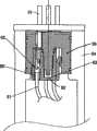
图2是图1的混合式压缩机的端子部的放大纵剖视图。Fig. 2 is an enlarged longitudinal sectional view of a terminal portion of the hybrid compressor of Fig. 1 .
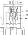
图3是表示图2的端子部结构的变形例的纵剖视图。FIG. 3 is a longitudinal sectional view showing a modified example of the terminal portion structure in FIG. 2 .
图4是以往用树脂来浇注成形时的端子部的纵剖视图。Fig. 4 is a vertical cross-sectional view of a terminal portion conventionally molded with resin.
(符号说明)(Symbol Description)
1作为电动压缩机的混合式压缩机1 Hybrid compressor as electric compressor
2第一压缩机构2 first compression mechanism
3第二压缩机构3 second compression mechanism
10、30定涡盘10, 30 Fixed vortex
11、31动涡盘11, 31 moving scroll
12、32工作空间(流体槽腔)12, 32 working space (fluid tank cavity)
13、33驱动轴13, 33 drive shaft
15电磁离合器15 electromagnetic clutch
18吸入端口18 suction port
20、40吸入室20, 40 suction chamber
21、41输出孔21, 41 output hole
22、42输出通路22, 42 output channels
35电动马达35 electric motor
36转子36 rotors
37定子37 stator
38定子壳体38 stator housing
39连通路39 roads
43定涡盘部件43 fixed scroll parts
50端子部50 Terminals
51供电用外部端子51 External terminal for power supply
52来自定子的电线52 wires from stator
53连接部53 connection part
54中空突出部54 hollow protrusion
55盖子55 cover
56插头壳体56 plug housing
57插座壳体57 socket housing
58中空部58 hollow part
59支撑部59 support part
60中空部60 hollow part
61O形圈61 O-ring
62弹性体62 elastomer
63锁定机构63 locking mechanism
64、65爪64, 65 claws
66作为弹性部件的波形垫圈66 Wave washers as elastic components
67突起部67 protrusions
68平垫圈68 flat washers
69O形圈69 O-ring
70作为保持部件的压板70 as a pressure plate for holding parts
71电线保持装置71 wire retention device
80电线保持装置80 wire retention device
81电线81 wire
82端子82 terminals
83插座壳体83 socket housing
具体实施方式Detailed ways
下面参照附图对本发明的最佳实施形态进行说明。The best embodiments of the present invention will be described below with reference to the accompanying drawings.
图1表示的是本发明一实施形态的电动压缩机,尤其表示的是将本发明应用在混合式压缩机中的场合。图2表示的是图1所示混合式压缩机的内置电动马达的端子连接部的提高抗振性的结构,但该图2所示的结构并不限定于应用于混合式压缩机,也可应用于仅将内置电动马达作为唯一的驱动源的电动压缩机。FIG. 1 shows an electric compressor according to an embodiment of the present invention, and particularly shows a case where the present invention is applied to a hybrid compressor. Fig. 2 shows the structure for improving the vibration resistance of the terminal connection part of the built-in electric motor of the hybrid compressor shown in Fig. 1, but the structure shown in Fig. 2 is not limited to the application to the hybrid compressor, and may also Applied to electric compressors that only use the built-in electric motor as the only driving source.
首先对图1所示的混合式压缩机进行说明。混合式压缩机1由涡旋式压缩机构成,具有第一压缩机构2和第二压缩机构3。第一压缩机构2包括:定涡盘10;动涡盘11,与定涡盘10啮合而形成多对工作空间(流体槽腔)12;驱动轴13,与动涡盘11卡合而使动涡盘11旋转运动;电磁离合器15,使带轮14与驱动轴13之间的驱动力传递通断,来自作为第一驱动源的车辆行驶用原动机(未图示)的驱动力传递给带轮14;球状联轴器16,阻止动涡盘11自转,作为止转装置;以及在外壳17上形成的吸入口18。从吸入口18经由吸入通路19吸入到吸入室20内的被压缩气体(例如制冷剂气体)被收集到工作空间12内,工作空间12一边使体积减少一边向定涡盘10的中心移动,从而压缩工作空间12内的制冷剂气体。在定涡盘10的中央部形成有输出孔21,被压缩后的制冷剂气体经由输出孔21、输出通路22、输出口23向外部制冷剂回路的高压侧流出。First, the hybrid compressor shown in FIG. 1 will be described. The hybrid compressor 1 is composed of a scroll compressor and has a
另一方面,第二压缩机构3包括:定涡盘30;动涡盘31,与定涡盘30啮合而形成多对工作空间(流体槽腔)32;驱动轴33,与动涡盘31卡合而使动涡盘31旋转运动;以及阻止动涡盘31自转的作为止转装置的球状联轴器34。为了驱动该第二压缩机构3的驱动轴33而内置有电动马达35。电动马达35具有固定在驱动轴33上的转子36和定子37,定子37固定在定子壳体38上或固定在作为压缩机壳体的一部分而形成的定子壳体38上,且电动马达35整体收容在定子壳体38内。在所述第二压缩机构3中,从吸入口18吸入第一压缩机构2的吸入室20内的被压缩气体(例如制冷剂气体)经由连通路39吸入第二压缩机构3的吸入室40中,进而被收集到工作空间32内,工作空间32-边使体积减少一边向定涡盘30的中心移动,从而压缩工作空间32内的制冷剂气体。在定涡盘30的中央部形成有输出孔41,被压缩后的制冷剂气体经由输出孔41、输出通路42而向外部制冷剂回路的高压侧流出。On the other hand, the second compression mechanism 3 includes: a fixed scroll 30; a movable scroll 31, which engages with the fixed scroll 30 to form multiple pairs of working spaces (fluid grooves) 32; a drive shaft 33, which is engaged with the movable scroll 31 Combined to make the movable scroll 31 rotate; and the
在本实施形态中,第一压缩机构2的定涡盘10与第二压缩机构3的定涡盘30背靠背地配设,且两个定涡盘10、30作为一体化的定涡盘部件43形成。In this embodiment, the fixed scroll 10 of the
在仅使混合式压缩机1的第一压缩机构2运行时,不对驱动第二压缩机构3的电动马达35供给电力,电动马达35不旋转。因此,第二压缩机构3不工作。在混合式压缩机1仅由电动马达35驱动时,电动马达35被启动而旋转,电动马达35的旋转传递给第二压缩机构3的驱动轴33,动涡盘31被驱动轴33驱动而旋转。此时,第一压缩机构2的电磁离合器15中没有通电,作为第一驱动源的车辆用原动机的旋转并不传递给第一压缩机构2。因此,第一压缩机构2不工作。在两个压缩机构2、3被同时驱动时,来自车辆用原动机的驱动力传递给第一压缩机构2的动涡盘11,且电动马达35被启动,其驱动力传递给第二压缩机构3的动涡盘31。When only the
在这样构成的作为电动压缩机的混合式压缩机1中,电动马达35的端子部50配置在装设形态下的混合式压缩机1的上部。该端子部50的详细情况如图2所示,具有电动马达35的供电用外部端子51与来自电动马达35的定子37的电线52的端部间的连接部53。连接部53配置在中空突出部54内,该中空突出部54形成在定子壳体38上并向外侧延伸,供电用外部端子51安装在盖子55上,该盖子55可实质地密闭所述中空突出部54。In the hybrid compressor 1 configured in this way as an electric compressor, the
在本实施形态中,所述连接部53通过连接器结构形成,该连接器结构包括:保持供电用外部端子51的插头壳体56;以及保持定子37的电线52的端部、与插头壳体56相互嵌合的插座壳体57。更具体而言,在插头壳体56的中央部形成有插座壳体57收容用的中空部58,并设置有朝下延伸的支撑部59。在该支撑部59上嵌合形成为有底状的插座壳体57的中空部60。In this embodiment, the connecting
在本实施形态中,作为连接部53的抗振装置,可同时采用如下的各种结构。但是,下面说明的抗振装置也可单独使用。在本实施形态中,首先,在插头壳体56的支撑部59的外周面与插座壳体57的中空部60的内周面之间夹设有O形圈61。该O形圈61主要起着在插头壳体56与插座壳体57之间的水平方向的防振作用。In this embodiment, as the anti-vibration means of the
此外,还具有介于插头壳体56的支撑部59的外端部(前端部)(根据与插座壳体57的嵌合结构不同,也可以是内端部)与插座壳体57的中空部60的内端部(底面部)(根据与插头壳体56的嵌合结构不同,也可以是外端部)之间的弹性体62。该弹性体62在本实施形态中由防振橡胶构成,由可沿其长度方向(轴向)压缩变形并可沿其径向膨胀的部件构成。即,通过成为压缩变形后的状态,可起到在插头壳体56的支撑部59的外端部与插座壳体57的中空部60的内端部之间的上下方向的防振作用,通过压缩而成为在径向上膨胀的状态,可起到在插头壳体56与插座壳体57之间的水平方向的防振作用。In addition, there is a hollow portion interposed between the outer end (front end) of the
此外,在插头壳体56的中空部58与插座壳体57的外周部之间设置有使两个壳体相互卡合的锁定机构63。在本实施形态中,在锁定机构63中,设在插头壳体56侧的爪64与设在插座壳体57侧的爪65相互卡合。采用这种结构,可防止插座壳体57从插头壳体56上脱开,且通过在卡合时从上方相对于插座壳体57相对地推压插头壳体56,可压缩固定所述弹性体62,使弹性体62发挥上述防振功能。Furthermore, a
此外,还设置有作为弹性部件的波形垫圈66,该波形垫圈可朝着压缩机壳体内、尤其在本实施形态中是朝着定子壳体38的中空突出部54内推压插头壳体56。该弹性部件也可以是波形垫圈66之外的发挥推压力的部件,例如其它弹簧部件。插头壳体56与在中空突出部54内形成的突起部67对碰,由波形垫圈66对盖子55的推压力予以保持。通过设置该波形垫圈66,可使其发挥插头壳体56的上下方向的防振功能。在该波形垫圈66与插头壳体56之间,为了防止因波形垫圈66的推压力而导致插头壳体56的表面变形,最好夹设有平垫圈68。Furthermore, a
此外,最好在插头壳体56的外周面与压缩机壳体之间、在本实施形态中是在与定子壳体38的中空突出部54的内周面之间夹设有O形圈69。通过夹设该O形圈69,可使其发挥插头壳体56的水平方向的防振功能。In addition, it is preferable that an O-
此外,在插座壳体57的下部安装有对来自定子37的电线52予以保持的作为保持部件的压板70,在该压板70上设置有弹性保持电线52的电线保持装置71。该电线保持装置71例如可由橡胶部件构成。电线52由电线保持装置71弹性保持,可提高该部分的抗振性。Also, a holding
该电线保持装置部分例如也可像图3所示那样构成。在图3所示的构成中,用于弹性保持来自定子37的电线81并由橡胶部件构成的保持装置80通过铆接等直接安装在电线81和/或端子82上,并在此状态下被嵌合在插座壳体83内而得以保持。若这样构成,则可废弃所述压板70,可实现装配性提高和成本降低。此外,由于可消除在来自定子37的电线81与插座壳体83之间的间隙并可废弃压板70,因此可提高该部分的绝缘性。The part of the wire holding device can also be constructed as shown in FIG. 3, for example. In the configuration shown in FIG. 3 , a holding
这样,通过具有如上所述的各种抗振中的至少一种,可提高马达用端子连接部的抗振性,可防止或抑制端子连接部的切断、瞬断的发生。此外,与上述用环氧树脂进行浇注成形的场合相比,可省去树脂准备和树脂固化的工夫,因此可确保良好的生产效率。In this way, by providing at least one of the above-mentioned various types of anti-vibration, the anti-vibration performance of the motor terminal connection portion can be improved, and the occurrence of disconnection and momentary disconnection of the terminal connection portion can be prevented or suppressed. In addition, compared with the above-mentioned case where epoxy resin is used for casting molding, the labor of resin preparation and resin curing can be saved, so that good production efficiency can be ensured.
工业上的可利用性Industrial availability
本发明可应用于内置有压缩机构驱动用电动马达的所有电动压缩机,尤其是还可应用于由可利用内置电动马达以及此外的驱动源来驱动各压缩机构的混合式压缩机构成的电动压缩机。The present invention can be applied to all electric compressors having a built-in electric motor for driving the compression mechanism, and in particular, can also be applied to electric compressors composed of a hybrid compressor that can drive each compression mechanism with a built-in electric motor and other driving sources. machine.
Claims (16)
Applications Claiming Priority (3)
| Application Number | Priority Date | Filing Date | Title |
|---|---|---|---|
| JP156757/2005 | 2005-05-30 | ||
| JP2005156757AJP5053523B2 (en) | 2004-12-24 | 2005-05-30 | Electric compressor |
| PCT/JP2006/309150WO2006129448A1 (en) | 2005-05-30 | 2006-05-02 | Electric compressor |
Publications (2)
| Publication Number | Publication Date |
|---|---|
| CN101184919A CN101184919A (en) | 2008-05-21 |
| CN101184919Btrue CN101184919B (en) | 2010-04-21 |
Family
ID=37481380
Family Applications (1)
| Application Number | Title | Priority Date | Filing Date |
|---|---|---|---|
| CN2006800190438AExpired - Fee RelatedCN101184919B (en) | 2005-05-30 | 2006-05-02 | Electric compressor |
Country Status (5)
| Country | Link |
|---|---|
| US (1) | US8235687B2 (en) |
| EP (1) | EP1887225A4 (en) |
| CN (1) | CN101184919B (en) |
| CA (1) | CA2610060C (en) |
| WO (1) | WO2006129448A1 (en) |
Families Citing this family (12)
| Publication number | Priority date | Publication date | Assignee | Title |
|---|---|---|---|---|
| US8939734B2 (en)* | 2007-08-28 | 2015-01-27 | Emerson Climate Technologies, Inc. | Molded plug for a compressor |
| JP5308650B2 (en)* | 2007-10-23 | 2013-10-09 | サンデン株式会社 | Electric compressor terminal device |
| CN102272455B (en)* | 2009-01-09 | 2015-02-25 | 艾默生环境优化技术有限公司 | Compressor with terminal plug assembly |
| US8939735B2 (en) | 2009-03-27 | 2015-01-27 | Emerson Climate Technologies, Inc. | Compressor plug assembly |
| FR2975447B1 (en)* | 2011-05-19 | 2013-05-31 | Valeo Thermal Sys Japan Co | MODULAR ELECTRIC COMPRESSOR WITH ASSEMBLY DEVICE |
| US9480177B2 (en) | 2012-07-27 | 2016-10-25 | Emerson Climate Technologies, Inc. | Compressor protection module |
| JP5518169B1 (en)* | 2012-12-12 | 2014-06-11 | 三菱重工業株式会社 | Electric compressor and method for assembling the same |
| CN104295496B (en)* | 2014-10-22 | 2018-09-11 | 广东美芝制冷设备有限公司 | External-rotor-type compressor |
| DE102015114192A1 (en)* | 2015-08-26 | 2017-03-02 | Ebm-Papst Mulfingen Gmbh & Co. Kg | Connection system for plug positioning |
| DE102016202226A1 (en)* | 2016-02-15 | 2017-08-17 | Bühler Motor GmbH | Brushless DC motor for driving a pump |
| DE102016204971A1 (en)* | 2016-03-24 | 2017-09-28 | Robert Bosch Gmbh | Spring ring, and an electric machine including such, as well as a method for producing an electrical machine |
| CN112943576B (en)* | 2021-04-15 | 2024-05-17 | 苏州大学张家港工业技术研究院 | Moving coil type linear opposed oscillation compressor capable of eliminating flying lead fatigue |
Citations (2)
| Publication number | Priority date | Publication date | Assignee | Title |
|---|---|---|---|---|
| CN1405452A (en)* | 2001-09-14 | 2003-03-26 | 三电有限公司 | Compound compressor |
| CN1530551A (en)* | 2003-03-11 | 2004-09-22 | Motor-driven compressor with insulation power-supply part |
Family Cites Families (15)
| Publication number | Priority date | Publication date | Assignee | Title |
|---|---|---|---|---|
| US3457867A (en)* | 1968-01-25 | 1969-07-29 | Red Jacket Mfg Co | Fluid pumping system |
| JPS5937862U (en)* | 1982-08-31 | 1984-03-09 | 株式会社東芝 | compressor terminal protection box |
| JPS59110896A (en)* | 1982-12-15 | 1984-06-26 | Ebara Corp | Submersible motor pump |
| US4836794A (en)* | 1988-08-05 | 1989-06-06 | Kern Engineering & Mfg. Corp. | EMI and environmentally protected connector cap |
| JPH0417787A (en)* | 1990-05-07 | 1992-01-22 | Sanyo Electric Co Ltd | Closed type compressor |
| JP3047159B2 (en)* | 1995-11-09 | 2000-05-29 | 矢崎総業株式会社 | Connector mating structure |
| JP3259817B2 (en)* | 1996-02-09 | 2002-02-25 | 矢崎総業株式会社 | Waterproof connector with cover |
| JP3742887B2 (en)* | 1997-06-18 | 2006-02-08 | ダイキン工業株式会社 | Scroll compressor |
| JP2001085111A (en)* | 1999-09-10 | 2001-03-30 | Sumitomo Wiring Syst Ltd | Connector |
| JP2002155862A (en)* | 2000-11-22 | 2002-05-31 | Toyota Industries Corp | Compressor |
| JP2002276550A (en)* | 2001-03-14 | 2002-09-25 | Matsushita Electric Ind Co Ltd | Method for connecting compressor with built-in motor to external wiring, connectors used for the same, compressor with built-in motor using them |
| AU2003200332B2 (en)* | 2002-02-08 | 2005-11-17 | Sanden Corporation | Hybrid compressor |
| JP3654272B2 (en)* | 2002-08-26 | 2005-06-02 | アイシン・エィ・ダブリュ株式会社 | Wiring connection device for vehicle motor |
| US7197892B2 (en)* | 2003-06-11 | 2007-04-03 | Denso Corporation | Encapsulated electrically driven compressor |
| JP4090409B2 (en)* | 2003-09-10 | 2008-05-28 | 日本圧着端子製造株式会社 | Connector housing structure |
- 2006
- 2006-05-02CNCN2006800190438Apatent/CN101184919B/ennot_activeExpired - Fee Related
- 2006-05-02EPEP06746000Apatent/EP1887225A4/ennot_activeWithdrawn
- 2006-05-02WOPCT/JP2006/309150patent/WO2006129448A1/enactiveApplication Filing
- 2006-05-02USUS11/915,931patent/US8235687B2/ennot_activeExpired - Fee Related
- 2006-05-02CACA2610060Apatent/CA2610060C/ennot_activeExpired - Fee Related
Patent Citations (2)
| Publication number | Priority date | Publication date | Assignee | Title |
|---|---|---|---|---|
| CN1405452A (en)* | 2001-09-14 | 2003-03-26 | 三电有限公司 | Compound compressor |
| CN1530551A (en)* | 2003-03-11 | 2004-09-22 | Motor-driven compressor with insulation power-supply part |
Also Published As
| Publication number | Publication date |
|---|---|
| EP1887225A4 (en) | 2012-11-28 |
| CA2610060C (en) | 2012-03-13 |
| US8235687B2 (en) | 2012-08-07 |
| CN101184919A (en) | 2008-05-21 |
| CA2610060A1 (en) | 2006-12-07 |
| WO2006129448A1 (en) | 2006-12-07 |
| EP1887225A1 (en) | 2008-02-13 |
| US20090129954A1 (en) | 2009-05-21 |
Similar Documents
| Publication | Publication Date | Title |
|---|---|---|
| CN101184919B (en) | Electric compressor | |
| CN101346547B (en) | Electric compressor | |
| CN102272455B (en) | Compressor with terminal plug assembly | |
| KR102583934B1 (en) | Compressor | |
| CN104838139B (en) | Electric compressor, and assembly method thereof | |
| JP6156705B2 (en) | Electric compressor | |
| US7806712B2 (en) | Electric compressor | |
| WO2006112268A1 (en) | Scroll fluid machine | |
| US20190052144A1 (en) | Compressor | |
| US10215026B2 (en) | Pump module and electric pump including the same | |
| WO2008102697A1 (en) | Electric compressor | |
| EP1867874B1 (en) | Electric motor-driven compressor | |
| KR20220157178A (en) | Terminal unit and electric compressor including the same | |
| US20060068626A1 (en) | Terminal connection structure of motor incorporated within a compressor | |
| JP5053523B2 (en) | Electric compressor | |
| US20100247353A1 (en) | Terminal device for electric compressor | |
| JP2007315222A (en) | Electric compressor | |
| JP2012021473A (en) | Electric compressor | |
| JP2006283738A (en) | Motor-driven compressor | |
| JP2007292022A (en) | Compressor |
Legal Events
| Date | Code | Title | Description |
|---|---|---|---|
| C06 | Publication | ||
| PB01 | Publication | ||
| C10 | Entry into substantive examination | ||
| SE01 | Entry into force of request for substantive examination | ||
| C14 | Grant of patent or utility model | ||
| GR01 | Patent grant | ||
| C17 | Cessation of patent right | ||
| CF01 | Termination of patent right due to non-payment of annual fee | Granted publication date:20100421 Termination date:20140502 |