CN101181787A - Electric power tool with non-heating handle - Google Patents
Electric power tool with non-heating handleDownload PDFInfo
- Publication number
- CN101181787A CN101181787ACNA2007101870350ACN200710187035ACN101181787ACN 101181787 ACN101181787 ACN 101181787ACN A2007101870350 ACNA2007101870350 ACN A2007101870350ACN 200710187035 ACN200710187035 ACN 200710187035ACN 101181787 ACN101181787 ACN 101181787A
- Authority
- CN
- China
- Prior art keywords
- motor
- power tool
- resistor
- handle
- circuit
- Prior art date
- Legal status (The legal status is an assumption and is not a legal conclusion. Google has not performed a legal analysis and makes no representation as to the accuracy of the status listed.)
- Pending
Links
Images


Classifications
- B—PERFORMING OPERATIONS; TRANSPORTING
- B25—HAND TOOLS; PORTABLE POWER-DRIVEN TOOLS; MANIPULATORS
- B25F—COMBINATION OR MULTI-PURPOSE TOOLS NOT OTHERWISE PROVIDED FOR; DETAILS OR COMPONENTS OF PORTABLE POWER-DRIVEN TOOLS NOT PARTICULARLY RELATED TO THE OPERATIONS PERFORMED AND NOT OTHERWISE PROVIDED FOR
- B25F5/00—Details or components of portable power-driven tools not particularly related to the operations performed and not otherwise provided for
- B25F5/008—Cooling means
- B—PERFORMING OPERATIONS; TRANSPORTING
- B25—HAND TOOLS; PORTABLE POWER-DRIVEN TOOLS; MANIPULATORS
- B25F—COMBINATION OR MULTI-PURPOSE TOOLS NOT OTHERWISE PROVIDED FOR; DETAILS OR COMPONENTS OF PORTABLE POWER-DRIVEN TOOLS NOT PARTICULARLY RELATED TO THE OPERATIONS PERFORMED AND NOT OTHERWISE PROVIDED FOR
- B25F5/00—Details or components of portable power-driven tools not particularly related to the operations performed and not otherwise provided for
- B25F5/02—Construction of casings, bodies or handles
Landscapes
- Engineering & Computer Science (AREA)
- Mechanical Engineering (AREA)
- Control Of Direct Current Motors (AREA)
- Portable Power Tools In General (AREA)
Abstract
Translated fromChinese
Description
Translated fromChinese技术领域technical field
本发明涉及一种电动力工具(后面简称为“动力工具”),特别涉及一种在电机控制电路中使用的生热电阻的布置。The present invention relates to an electric power tool (hereinafter simply referred to as "power tool"), in particular to an arrangement of a heat generating resistor used in a motor control circuit.
背景技术Background technique
例如,在日本专利申请公布No.2002-281777中公开了一种传统的动力工具和用于其中的电机控制电路。图1是传统的冲击驱动器10的局部截面图,图2是用于图1所示的冲击驱动器10的电机控制电路20的电路图。For example, a conventional power tool and a motor control circuit therefor are disclosed in Japanese Patent Application Publication No. 2002-281777. FIG. 1 is a partial sectional view of a conventional impact driver 10, and FIG. 2 is a circuit diagram of a motor control circuit 20 for the impact driver 10 shown in FIG.
图2中显示的电机控制电路20包括速度可控开关2,二极管桥3,正向/反向转换电路5,DC电机6和制动电路4。速度可控开关1连接到商业AC电源1,并且根据冲击驱动器10的触发开关7被拉的深度来操作应用到DC电机6的电压。二极管桥3对AC电压进行半波或者全波整流,并通过正向/反向开光转换电路5将DC电压供给到DC电机6。The motor control circuit 20 shown in FIG. 2 includes a speed
制动电路4是由常闭触点4a(后面,称为“NC触点4a”)和电阻线圈4b构造。NC触点4a和电阻线圈4b通过DC侧的正极A和负极B串联连接,从而通过电机6,电阻线圈4b和NC触点4a在NC触点4a闭合时形成闭环。The
当操作者从触发开关7移动他或她的手指,以停止驱动冲击驱动器10时,速度可控开关2关闭,制动电路4的NC触点4a打开,以让再生电流或者制动电路Ix在由电机6、电阻线圈4b和NC触点4a形成的闭环内流动。When the operator moves his or her finger from the trigger switch 7 to stop driving the impact driver 10, the speed
如图1所示,安装有电阻线圈4b的板8设置在把手部11a的内部和触发开关7的后面。当利用冲击驱动器10将多个小尺寸的螺钉连续地钉入加工件时,触发开关7反复地开启或者关闭。触发开关7每次关闭时,制动电流在电阻线圈4b内流动,并且产生热。由于通过电阻线圈4b产生的热,手柄11的把手部11a会热到操作者不能继续抓住冲击驱动器10的程度。As shown in FIG. 1 , a
发明内容Contents of the invention
考虑到上面,本发明的目的是克服在传统的动力工具中所涉及的问题。In view of the above, it is an object of the present invention to overcome the problems involved in conventional power tools.
为实现上面和其它的目的,本发明提供了一种动力工具,该动力工具包括:电机;容纳该电机的主外壳;手柄;开关电路;和制动电路。手柄具有尾部和把手部。当驱动动力工具时,操作者抓握把手部。把手部具有与主外壳形成为一体的一端,而另一端与尾部形成一体。开关电路在动力源和电极之间连接,并控制电机。制动电路包括电阻器,并且连接到电机,当流进电机的驱动电流被截断时,用于允许电机产生的再生电流流动,其中,电阻器设置在当操作者抓握把手部时操作者的手正常不会延伸到的尾部。由此,由制动电路的电阻器所产生的热量不会使得把手部很热。To achieve the above and other objects, the present invention provides a power tool comprising: a motor; a main housing accommodating the motor; a handle; a switch circuit; and a brake circuit. The handle has a tail and a handle. When driving the power tool, the operator grasps the handle portion. The handle portion has one end integrally formed with the main housing and the other end integrally formed with the tail portion. A switching circuit is connected between the power source and the electrodes, and controls the motor. The brake circuit includes a resistor and is connected to the motor for allowing regenerative current generated by the motor to flow when the driving current flowing into the motor is cut off, wherein the resistor is provided at the operator's side when the operator grasps the handle portion. Tail to which the hand does not normally extend. Thereby, the heat generated by the resistors of the brake circuit does not make the handle part very hot.
期望的是,制动电路的电阻器由第一电阻器元件和第二电阻器元件互相并联构成。利用两个电阻器互相并联的连接,电阻值可以减小,由此降低由电阻器产生的热量。在这种情况下,考虑到有效地利用手柄的内部空间,进一步期望的是,将第一和第二电阻器元件分别安装到电路板的前表面和后表面上。Desirably, the resistor of the brake circuit is formed by a first resistor element and a second resistor element connected in parallel with each other. By connecting two resistors in parallel with each other, the resistance value can be reduced, thereby reducing the heat generated by the resistors. In this case, it is further desirable to mount the first and second resistor elements on the front and rear surfaces of the circuit board, respectively, in consideration of efficient use of the internal space of the handle.
期望的是,制动电路进一步包括当驱动电流流进电机时保持打开而当流进电机的驱动电流被截断时被闭合的触点。Desirably, the brake circuit further includes contacts that remain open when drive current flows into the motor and are closed when drive current flow into the motor is interrupted.
还期望的是,尾部在主外壳的轴向方向从把手部向外突出。It is also desirable that the tail portion protrudes outward from the handle portion in the axial direction of the main housing.
附图说明Description of drawings
本发明的具体特征和优点,以及其它目标随着结合附图进行的说明将变得清楚,其中:Specific features and advantages, as well as other objects, of the invention will become apparent from the description read in conjunction with the accompanying drawings, in which:
图1是示出了传统的冲击驱动器部分的截面图;FIG. 1 is a sectional view showing part of a conventional impact driver;
图2是示出了用于图1中所示的冲击驱动器的电机控制电路的电路图;FIG. 2 is a circuit diagram showing a motor control circuit for the impact driver shown in FIG. 1;
图3是示出了根据本发明的实施例的冲击驱动器的部分的横截面图;3 is a cross-sectional view showing part of an impact driver according to an embodiment of the present invention;
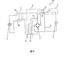
图4是示出了用于图3中所示的冲击驱动器的电机控制电路的电路图;FIG. 4 is a circuit diagram showing a motor control circuit for the impact driver shown in FIG. 3;
图5A是示出了根据本发明的实施例的用于安装制动电阻器的电路板的后视图;5A is a rear view showing a circuit board for mounting a brake resistor according to an embodiment of the present invention;
图5B是示出了根据本发明的另一实施例的用于安装制动电阻器的电路板的后视图;以及5B is a rear view showing a circuit board for mounting a braking resistor according to another embodiment of the present invention; and
图6是示出冲击驱动器的把手部的侧视图。Fig. 6 is a side view showing the handle portion of the impact driver.
具体实施方式Detailed ways
下面参考图3-6,对本发明的实施例进行说明,其中本发明是应用于冲击驱动器。在图2和4中的电路图中,相同或相应的元件通过相同的附图标记来表示。An embodiment of the present invention, in which the present invention is applied to an impact driver, will be described below with reference to FIGS. 3-6. In the circuit diagrams in FIGS. 2 and 4 , identical or corresponding elements are indicated by the same reference numerals.
如图3所示,冲击驱动器30包括主外壳31和手柄11,该手柄大体垂直于主外壳31的轴向方向延伸,但是略微偏向主外壳31的最后端。手柄11具有在一侧结合到主外壳31的把手部11a,并且与主外壳31形成为一体。另外,手柄11具有与把手部11a形成为一体的尾部11b。As shown in FIG. 3 , the
DC电机6坐落在主外壳31的后部。尽管在图3中未显示,但是冲击机构也容纳在主外壳31内,当从DC电机6供给驱动动力时,用于产生冲击和驱动力。在冲击和驱动动力的作用下,连接件(例如螺纹)被紧固到加工件内。开关电路板32设置在把手部53a的上部,且位于触发开关(trigger switch)7的后面。The
如图6所示,把手部11a是在驱动冲击驱动器30时,操作者抓取的部分。把手部11a具有适合于人手的一般尺寸的大小。当操作者抓住把手部11a时,操作者的手一般不会延伸到尾部11b。尾部11b从抓手部11a在主外壳31的轴向方向向外突出,从而使得当冲击驱动器30被操作者将上部朝下(倒置地)把持时,冲击驱动器30不会轻易地掉下。As shown in FIG. 6 , the
如图4所示,电机控制电路40包括由速度可控开关2和二极管桥3构成的开关电路。速度可控开关2是由两个常开触点(后面称为“NO触点”)2b和2c,以及并连到NO触点2b的半导体开关元件(thyristor)2a构成。NO触点2b和2c与触发开关7(见图3和6)一起操作。二极管桥3对AC电源(power supply)1的AC输出执行半波或者全波整流,并将DC动力应用到DC电机6。As shown in FIG. 4 , the
正向/反向转换(开关)电路5设置在二极管桥3和DC电机6之间。正向/反向转换电路5是由用于切换DC电机6的旋转方向的正向/反向转换触点5a和5b构成。进一步,电容9跨过AC电源1连接,用于抑制在操作冲击驱动器30时产生的噪声。A forward/reverse conversion (switch)
图4中的电机控制电路进一步包括制动电路4。制动电路4是由NC触点4a和两个互相并联的电阻器4c和4d构成。NC触点4a和并联的电阻器4c和4d通过二极管桥3的正极和负极串联连接。当NC触点4a关闭时,制动电路4与电机10和正向/反向转换电路5形成闭环。当速度可控开关2的两个NO触点3和4同时打开时,NC触点4a闭合。当操作者将他或她的手指从触发开关7移开时,这就会发生。The motor control circuit in FIG. 4 further includes a
操作中,当操作者将触发开关7拉至小于最大的水平时,NO触点2b闭合,NO触点2c保持打开。因此,驱动电流通过包括二极管桥3和正向/反向转换电路5的触点5a的路径流进电机6内,然后从DC电机6流出的电流在包括正向/反向转换(开关)电路5的触点5b、二极管桥3和半导体开关元件2a和速度可控开关2的NO触点2c的路径内流动。流进DC电机6的驱动电流与触发开关7被拉的水平或深度相对应。In operation, when the operator pulls the trigger switch 7 to a level less than the maximum, the NO
当操作者将触发开关7拉到最大或者到完全深度时,速度可控开关2的NO触点2b和2c均闭合。在这种情况下,二极管桥3执行AC电压的全波整流,从而使得驱动电流与触发开关7被拉到一半时的情况下相比大约为两倍。更具体地,除了在上述的路径内流动的驱动电流外,驱动电流还通过包括NO触点2b、二极管桥3、正向/反向转换电路5的触点5a的路径流进DC电机6,然后从DC电机6流出的电流在包括正向/反向转换电路5的触点5b、二极管桥3和NO触头2b的电路内流动。When the operator pulls the trigger switch 7 to the maximum or to full depth, the
当操作者从触发开关7移开他或她的手指时,NO触点2b和2c同时打开,并且同时,制动电路4的NC触点4a闭合。结果,由DC电机6产生的再生电流或制动电流在由制动电路4、正向/反向转换电路5和DC电机6构成的闭环内流动。由于两个电阻器4c和4d并联,流入每个电阻器4c和4d的制动电流被减小,由此与使用单个电阻器的情况相比,从这里产生的热量也减少了。When the operator removes his or her finger from the trigger switch 7, the
如图5A和5B所示,两个电阻器4c和4d中的一个安装在电路板33的后表面上,配对的电阻器4d安装在相同的电路板33的前表面上。安装两个电阻器4c和4d的电路板33设置在手柄11的尾部11b中。因此,由电阻器4c和4d产生的热基本上不会增大把手部11a处的温度。As shown in FIGS. 5A and 5B , one of the two
尽管参考具体实施例,对本发明进行了详细的说明,本领域的普通技术人员应该理解的是,可以对其进行各种变化和修改。例如,本发明可以不仅应用于冲击驱动器,而且还可以应用于使用DC电机的各种动力工具。Although the present invention has been described in detail with reference to specific embodiments, it will be understood by those skilled in the art that various changes and modifications can be made thereto. For example, the present invention can be applied not only to impact drivers but also to various power tools using DC motors.
Claims (5)
Translated fromChineseApplications Claiming Priority (2)
| Application Number | Priority Date | Filing Date | Title |
|---|---|---|---|
| JP2006312139AJP2008126344A (en) | 2006-11-17 | 2006-11-17 | Electric tool |
| JP2006312139 | 2006-11-17 |
Publications (1)
| Publication Number | Publication Date |
|---|---|
| CN101181787Atrue CN101181787A (en) | 2008-05-21 |
Family
ID=39043177
Family Applications (1)
| Application Number | Title | Priority Date | Filing Date |
|---|---|---|---|
| CNA2007101870350APendingCN101181787A (en) | 2006-11-17 | 2007-11-19 | Electric power tool with non-heating handle |
Country Status (4)
| Country | Link |
|---|---|
| US (1) | US20080135268A1 (en) |
| EP (1) | EP1923178B1 (en) |
| JP (1) | JP2008126344A (en) |
| CN (1) | CN101181787A (en) |
Cited By (4)
| Publication number | Priority date | Publication date | Assignee | Title |
|---|---|---|---|---|
| CN102335895A (en)* | 2010-07-14 | 2012-02-01 | 日立工机株式会社 | Power tool having circuit board |
| CN103429159A (en)* | 2011-03-09 | 2013-12-04 | 皇家飞利浦有限公司 | Imaging system subject support |
| CN103962631A (en)* | 2013-02-01 | 2014-08-06 | 株式会社牧田 | Power tool and portable circular saw |
| CN104755231A (en)* | 2012-10-29 | 2015-07-01 | 日立工机株式会社 | Electrical power tool |
Families Citing this family (8)
| Publication number | Priority date | Publication date | Assignee | Title |
|---|---|---|---|---|
| JP5512110B2 (en)* | 2008-09-26 | 2014-06-04 | 株式会社マキタ | Electric tool |
| US8179004B2 (en)* | 2009-11-06 | 2012-05-15 | Shop Vac Corporation | Motor assembly with switch module |
| JP5374331B2 (en)* | 2009-11-25 | 2013-12-25 | パナソニック株式会社 | Rotating tool |
| JP5679512B2 (en)* | 2010-12-28 | 2015-03-04 | 日立工機株式会社 | Electric tool |
| JP5936302B2 (en) | 2010-12-28 | 2016-06-22 | 日立工機株式会社 | Electric tool |
| US10821591B2 (en) | 2012-11-13 | 2020-11-03 | Milwaukee Electric Tool Corporation | High-power cordless, hand-held power tool including a brushless direct current motor |
| DE102016003255A1 (en)* | 2016-03-16 | 2017-09-21 | Andreas Stihl Ag & Co. Kg | Electronic control unit for operating an electric motor with a braking resistor |
| EP3981066A4 (en) | 2019-06-10 | 2023-02-08 | Milwaukee Electric Tool Corporation | MOTOR BRAKING USING SELECTIVELY LINKABLE RESISTOR |
Family Cites Families (12)
| Publication number | Priority date | Publication date | Assignee | Title |
|---|---|---|---|---|
| US3721879A (en)* | 1965-07-02 | 1973-03-20 | Arrow Hart Inc | Power control for portable electric tool |
| US3774095A (en)* | 1972-09-20 | 1973-11-20 | Westinghouse Air Brake Co | System for blending regenerative and dynamic and friction braking |
| US3970912A (en)* | 1973-08-28 | 1976-07-20 | Hoffman Philip A | Battery charging circuit |
| US3890551A (en)* | 1974-01-24 | 1975-06-17 | Gen Electric | Regenerative braking circuit |
| US4084123A (en)* | 1975-08-25 | 1978-04-11 | Disston, Inc. | Cordless electric devices having rechargeable battery pack(s) |
| US4243919A (en)* | 1980-03-31 | 1981-01-06 | The Singer Company | Motor braking arrangement |
| US5757154A (en)* | 1993-07-09 | 1998-05-26 | Ryobi Motor Products Corp. | Electric motor braking circuit arrangement |
| JP3618697B2 (en) | 2001-01-11 | 2005-02-09 | リョービ株式会社 | Power tool switch circuit |
| US20020158593A1 (en)* | 2001-04-27 | 2002-10-31 | Henderson Jeffery L. | Circuit for controlling dynamic braking of a motor shaft in a power tool |
| US6552904B2 (en)* | 2001-08-13 | 2003-04-22 | Black & Decker Inc. | Power tool with heat sink assembly |
| JP2005297120A (en)* | 2004-04-09 | 2005-10-27 | Hitachi Koki Co Ltd | Electric tool |
| JP4692288B2 (en)* | 2006-01-11 | 2011-06-01 | 日立工機株式会社 | Electric tool and assembling method thereof |
- 2006
- 2006-11-17JPJP2006312139Apatent/JP2008126344A/ennot_activeWithdrawn
- 2007
- 2007-11-16EPEP07022330.0Apatent/EP1923178B1/ennot_activeExpired - Fee Related
- 2007-11-16USUS11/941,430patent/US20080135268A1/ennot_activeAbandoned
- 2007-11-19CNCNA2007101870350Apatent/CN101181787A/enactivePending
Cited By (9)
| Publication number | Priority date | Publication date | Assignee | Title |
|---|---|---|---|---|
| CN102335895A (en)* | 2010-07-14 | 2012-02-01 | 日立工机株式会社 | Power tool having circuit board |
| US8928261B2 (en) | 2010-07-14 | 2015-01-06 | Hitachi Koki Co., Ltd. | Power tool having circuit board |
| US9882452B2 (en) | 2010-07-14 | 2018-01-30 | Hitachi Koki Co., Ltd. | Power tool having circuit board |
| CN103429159A (en)* | 2011-03-09 | 2013-12-04 | 皇家飞利浦有限公司 | Imaging system subject support |
| CN103429159B (en)* | 2011-03-09 | 2016-08-10 | 皇家飞利浦有限公司 | Imaging system subject support |
| CN104755231A (en)* | 2012-10-29 | 2015-07-01 | 日立工机株式会社 | Electrical power tool |
| CN104755231B (en)* | 2012-10-29 | 2017-06-06 | 日立工机株式会社 | electrical tools |
| US10536056B2 (en) | 2012-10-29 | 2020-01-14 | Koki Holdings Co., Ltd. | Electric power tool |
| CN103962631A (en)* | 2013-02-01 | 2014-08-06 | 株式会社牧田 | Power tool and portable circular saw |
Also Published As
| Publication number | Publication date |
|---|---|
| EP1923178A1 (en) | 2008-05-21 |
| EP1923178B1 (en) | 2013-06-19 |
| US20080135268A1 (en) | 2008-06-12 |
| JP2008126344A (en) | 2008-06-05 |
Similar Documents
| Publication | Publication Date | Title |
|---|---|---|
| CN101181787A (en) | Electric power tool with non-heating handle | |
| US20200186006A1 (en) | Handheld power tool with a brushless electric motor | |
| CN103386673B (en) | Electric tool | |
| CN105473287B (en) | Electric tool | |
| JP5190774B2 (en) | Electric tool | |
| CN207251389U (en) | Electric tool | |
| US20240292541A1 (en) | Electronic switch module with oppositely-arranged power switches and discrete heat sinks | |
| JP6032445B2 (en) | Electric tool | |
| CN204658375U (en) | Power tool | |
| WO2014069369A1 (en) | Electrical power tool | |
| CN105209222A (en) | Power tool | |
| JP7131619B2 (en) | electric work machine | |
| CN218788734U (en) | Power tool and brake system for power tool | |
| EP3959811A1 (en) | Motor braking coil for a power tool | |
| JP2007301703A (en) | Electric power tool | |
| JP5570933B2 (en) | Electric tool | |
| TWI819465B (en) | Tools having housings, motor controllers for motors, and motors adapted to be powered by power sources | |
| JP2014240120A (en) | Electric power tool | |
| JP2006315117A (en) | Cordless power tool | |
| JP3618697B2 (en) | Power tool switch circuit | |
| JP7734538B2 (en) | electric work equipment | |
| US20220293358A1 (en) | Integrated electronic switch and power tool | |
| JP2002281777A5 (en) | ||
| JP6953803B2 (en) | Electric tool | |
| TWI599146B (en) | Electric grinding machine with switched reluctance motor |
Legal Events
| Date | Code | Title | Description |
|---|---|---|---|
| C06 | Publication | ||
| PB01 | Publication | ||
| C10 | Entry into substantive examination | ||
| SE01 | Entry into force of request for substantive examination | ||
| C02 | Deemed withdrawal of patent application after publication (patent law 2001) | ||
| WD01 | Invention patent application deemed withdrawn after publication |