CN101180749B - Battery module and manufacturing method thereof - Google Patents
Battery module and manufacturing method thereofDownload PDFInfo
- Publication number
- CN101180749B CN101180749BCN2006800181617ACN200680018161ACN101180749BCN 101180749 BCN101180749 BCN 101180749BCN 2006800181617 ACN2006800181617 ACN 2006800181617ACN 200680018161 ACN200680018161 ACN 200680018161ACN 101180749 BCN101180749 BCN 101180749B
- Authority
- CN
- China
- Prior art keywords
- battery
- mentioned
- frame
- cylindrical
- maintenance
- Prior art date
- Legal status (The legal status is an assumption and is not a legal conclusion. Google has not performed a legal analysis and makes no representation as to the accuracy of the status listed.)
- Expired - Fee Related
Links
Images


Classifications
- Y—GENERAL TAGGING OF NEW TECHNOLOGICAL DEVELOPMENTS; GENERAL TAGGING OF CROSS-SECTIONAL TECHNOLOGIES SPANNING OVER SEVERAL SECTIONS OF THE IPC; TECHNICAL SUBJECTS COVERED BY FORMER USPC CROSS-REFERENCE ART COLLECTIONS [XRACs] AND DIGESTS
- Y02—TECHNOLOGIES OR APPLICATIONS FOR MITIGATION OR ADAPTATION AGAINST CLIMATE CHANGE
- Y02E—REDUCTION OF GREENHOUSE GAS [GHG] EMISSIONS, RELATED TO ENERGY GENERATION, TRANSMISSION OR DISTRIBUTION
- Y02E60/00—Enabling technologies; Technologies with a potential or indirect contribution to GHG emissions mitigation
- Y02E60/10—Energy storage using batteries
Landscapes
- Battery Mounting, Suspending (AREA)
- Connection Of Batteries Or Terminals (AREA)
Abstract
Description
Translated fromChinese技术领域technical field
本发明涉及将为了得到所要输出电压所需要个数的单电池排列并电连接、并且机械性地连结而构成的电池模块和能够以高生产率组装该电池模块的制造方法。The present invention relates to a battery module configured by arranging and electrically connecting cells required to obtain a desired output voltage, and to a manufacturing method capable of assembling the battery module with high productivity.
背景技术Background technique
近年来,AV设备或个人计算机和便携式通信设备等电子设备的便携化和电池化快速发展,作为这些电气设备的驱动电源,由于可靠性高并且维护容易,因此,使用了镍镉蓄电池、镍氢蓄电池或者锂离子二次电池等。In recent years, the portability and batteryization of electronic equipment such as AV equipment, personal computers, and portable communication equipment have rapidly developed. As the driving power supply of these electrical equipment, nickel-cadmium storage batteries, nickel-metal hydride batteries, and nickel-metal hydride batteries are used due to their high reliability and easy maintenance Storage battery or lithium ion secondary battery, etc.
另一方面,在混合型电动汽车中,通过组合内燃机,作为用于行驶驱动源的电池驱动电动机的电力源,使用了镍氢蓄电池。此外,在由于地震和台风等灾害所发生停电时的后备用应急电源装置等的用途中,当前主要采用铅蓄电池,但是期望将来大容量并且能大电流放电的镍氢蓄电池的实用化。另外,也期待将具有大容量的镍氢蓄电池用在无人通信基站等应急电源装置和电车的导电弓架升降用电源装置或电车供电停止时使用的照明点灯用后备电源装置等铁道用电源装置的用途中。On the other hand, in a hybrid electric vehicle, a nickel-metal hydride storage battery is used as a power source for a battery-driven electric motor used as a driving source in combination with an internal combustion engine. In addition, lead storage batteries are currently mainly used in applications such as backup emergency power supply devices during power outages due to disasters such as earthquakes and typhoons, but the practical use of nickel metal hydride storage batteries with large capacity and high current discharge is expected in the future. In addition, it is also expected to use large-capacity nickel-metal hydride batteries in emergency power supply devices such as unmanned communication base stations, power supply devices for pantograph raising and lowering of trams, and power supply devices for railways such as backup power supply devices for lighting and lighting used when the power supply of trams is stopped. in use.
如上所述的电源装置一般是相互连接了多个圆筒形电池中的各个异极电源端子间而构成电池模块,相互连接了用于得到所要输出电压的需要个数的该电池模块来组装成电池包。本发明申请人首先提出了对于振动和冲击具有强牢固性的电池模块(例如,参照专利文献1)。The above-mentioned power supply device generally forms a battery module by interconnecting power supply terminals of different polarities in a plurality of cylindrical batteries, and assembles a battery module by interconnecting a required number of the battery modules for obtaining a desired output voltage. battery pack. The applicant of the present invention first proposed a battery module having strong robustness against vibration and shock (for example, refer to Patent Document 1).
上述电池模块的结构具有合成树脂制的支架箱,所述支架箱在具有与圆筒形电池的电池轴向的长度大致相等厚度的长方体中形成了一列或多列在厚度方向上贯通的电池收纳部,所述电池收纳部是具有与圆筒形电池的直径大致相等的一边的正视正方形的形状,所述电池模块利用平板状连接板相互电连接了一个个地收纳在各电池收纳部中的各圆筒形电池中的邻接的各2个圆筒形电池的异极间。相互连接邻接的各2个圆筒形电池的电池间连接结构在于,在圆筒形电池中形成在其外周附近的地方向轴向外方突出的环状的连接电极部,将平板状连接板跨架在邻接的各2个圆筒形电池中的一个连接电极部和另一个圆筒形电池的底面上,利用焊接分别接合了连接板与连接电极部和与电池壳体的底面的各个接触处。The structure of the above-mentioned battery module has a frame box made of synthetic resin, and the frame box has one or more rows of battery housings penetrating in the thickness direction in a cuboid having a thickness approximately equal to the length of the battery axial direction of the cylindrical battery. The battery storage section is in the shape of a square in front view with one side approximately equal to the diameter of the cylindrical battery, and the battery modules are electrically connected to each other by a flat connection plate and stored in each battery storage section one by one. Between different electrodes of two adjacent cylindrical batteries among the cylindrical batteries. The inter-battery connection structure for interconnecting two adjacent cylindrical batteries is to form a ring-shaped connecting electrode portion protruding axially outward in the vicinity of the outer periphery of the cylindrical battery, and connect a flat plate-shaped connecting plate to the cylindrical battery. One of the connecting electrode parts and the bottom surface of the other cylindrical battery of two adjacent cylindrical batteries are straddled, and the respective contacts of the connecting plate, the connecting electrode part, and the bottom surface of the battery case are respectively joined by welding. place.
该电池模块由于通过将各圆筒形电池收纳在各个电池收纳部中而保持在完全电气绝缘的状态下,因此,不需要绝缘环和外装管路,能够实现成本的降低和生产率的提高,由于在各圆筒形电池外周的4处与形成电池收纳部的4个隔壁相接的状态下固定各圆筒形电池,因此,起到对于振动和冲击不摇晃而可靠地保持的显著的效果。Since the battery module is kept in a completely electrically insulated state by accommodating each cylindrical battery in each battery accommodating portion, an insulating ring and an external piping are not required, and cost reduction and productivity improvement can be achieved, because Since each cylindrical battery is fixed in a state where four parts of the outer periphery of each cylindrical battery are in contact with the four partition walls forming the battery housing portion, there is a remarkable effect of reliably holding the battery without shaking against vibrations and impacts.
此外,作为现有的电池包,已知多个圆筒形电池构成电池模块将电气性且机械地串联了一列,在成为上方开口的正方形箱形的合成树脂制支架箱内按照多列多段的并列配置插入保持上述电池模块,在支架箱中的位于两端部的各端板上设置了电连接电池模块的端子间的母线(例如,参照专利文献2)。上述支架箱在两端壁上形成了电池模块的收纳个数的圆形的贯通孔,该圆形的贯通孔整体外形是细长圆柱状的用于插入电池模块,同时,在两端壁间平行地设置了用于稳定保持电池模块的中间壁,在该中间壁上还与两端壁同数量地开口了圆形的贯通孔。各电池模块插入到两端壁和中间壁的各贯通孔中,并保持在支架箱的固定位置上。In addition, as a conventional battery pack, it is known that a battery module composed of a plurality of cylindrical batteries is electrically and mechanically connected in series, and is arranged in parallel in multiple rows and stages in a square box-shaped synthetic resin holder box with an upper opening. The above-mentioned battery modules are arranged to be inserted and held, and bus bars for electrically connecting terminals of the battery modules are provided on each end plate at both ends of the frame box (for example, refer to Patent Document 2). The above-mentioned support box forms a circular through hole on the two ends of the wall to accommodate the number of battery modules. The overall shape of the circular through hole is a slender column for inserting the battery module. An intermediate wall for stably holding the battery module is provided, and the same number of circular through-holes as the two end walls are opened on the intermediate wall. Each battery module is inserted into each through-hole of both end walls and the middle wall, and is held in the fixed position of the bracket box.
该电池包能够显著地提高电池模块的支承强度和刚性,同时仅用螺栓等的紧固操作就能够将电池模块与母线结合,从而得到了向支架箱装入电池模块的操作变得简单容易的效果。This battery pack can remarkably improve the supporting strength and rigidity of the battery module, and at the same time, the battery module can be combined with the bus bar only by fastening operations such as bolts, so that the operation of loading the battery module into the bracket box becomes simple and easy. Effect.
专利文献1:日本特开2003-162993号公报Patent Document 1: Japanese Patent Laid-Open No. 2003-162993
专利文献2:日本特开平10-270006号公报Patent Document 2: Japanese Patent Application Laid-Open No. 10-270006
但是,在上述现有的电池模块中,预先决定了收纳在1个电池模块内的电池的个数,因此,在各使用者和用途要求不同形状的电池模块的情况下,就必须要重新设计和制造符合其形状的结构的电池模块,因此就有不能适时地响应要求的问题。除此以外还存在需要进一步改良的问题。即,上述电池模块通过盖住电池收纳部的两端开口的盖部件的散热用孔,使形成在收纳了各圆筒形电池的电池收纳部的四个角中的、圆筒形电池与电池收纳部的隔壁之间的空隙连通,从而确保散热用通路,利用在该散热用通路中流动的风来得到各圆筒形电池的冷却效果,因此,对于比较多地数量的圆筒形电池的冷却效果不够充分。However, in the conventional battery module described above, the number of batteries accommodated in one battery module is determined in advance. Therefore, when a battery module with a different shape is required for each user and application, it is necessary to redesign the battery module. And manufacture the battery module of the structure conforming to its shape, so there is a problem of not being able to respond to the demand in a timely manner. In addition, there are problems that need to be further improved. That is, the above-mentioned battery module connects the cylindrical batteries formed in the four corners of the battery storage part in which the respective cylindrical batteries are housed, through the heat dissipation holes of the cover member that covers the openings at both ends of the battery storage part. The gaps between the partition walls of the accommodating portion are communicated to ensure a passage for heat dissipation, and the cooling effect of each cylindrical battery is obtained by using the wind flowing in the passage for heat dissipation. Therefore, for a relatively large number of cylindrical batteries, The cooling effect is not sufficient.
且说,将来期待像具有100Ah左右的大容量和1.6Kg左右的比较大的重量的镍氢蓄电池这样的大型的圆筒形电池的实用化。但是可以想到,在现有的电池模块中,其结构上很难适用上述的大型的圆筒形电池使其实用化。这是因为,经过一个个地向支架箱的全部电池收纳部中插入圆筒形电池的工序和分别利用连接板的两端部的焊接相互连接被收纳到电池收纳部中的邻接的各2个圆筒形电池的焊接工序来制作上述电池模块,可以设想在经过这样的工序装入大型的圆筒形电池的情况下,操作性变差,生产性显著降低。此外,各圆筒形电池固定成如下利用闭塞支架箱的厚度方向上的两端开口的一对盖部件,将其闭合在电池收纳部中不在电池轴向上随便移动,因此,在使用大型的圆筒形电池的情况下,用于可靠地保持它们的牢固性不够,受到振动和冲击时的强度成问题。In addition, practical use of large cylindrical batteries such as nickel-hydrogen storage batteries having a large capacity of about 100 Ah and a relatively heavy weight of about 1.6 kg is expected in the future. However, it is conceivable that in the existing battery module, it is structurally difficult to apply the above-mentioned large cylindrical battery to make it practical. This is because the process of inserting cylindrical batteries one by one into all the battery storage parts of the stand box and the welding of the two ends of the connecting plate are connected to each other and each of the two adjacent batteries stored in the battery storage parts is connected to each other. The above-mentioned battery module is fabricated through the welding process of cylindrical batteries, and it is conceivable that, when a large cylindrical battery is incorporated through such a process, workability will be deteriorated and productivity will be significantly lowered. In addition, each cylindrical battery is fixed so that it is closed in the battery storage portion by a pair of cover members that block the openings at both ends in the thickness direction of the holder box, and is not moved in the battery axial direction. Therefore, when using a large In the case of cylindrical batteries, firmness for reliably holding them is insufficient, and strength against vibration and impact is problematic.
此外,在上述电池模块中,在支架箱的全部的各电池收纳部中收纳了圆筒形电池后,通过将跨架在邻接的各2个圆筒形电池上配置的连接板的两端部分与一个圆筒形电池的正极和另一个圆筒形电池的负极端子焊接结合,来相互电连接邻接的各2个圆筒形电池,经过上述这样的工序制成上述电池模块,但是在该焊接工序中向任何1个圆筒形电池的接合一失败,就必须要交换已经收纳在支架箱中的全部的圆筒形电池。另外,在该电池模块中成为通过已焊接在全部的圆筒形电池的电极端子上的连接板电连接了全部的圆筒形电池,因此,在维护时等认为一部分的圆筒形电池已消耗和劣化的情况下,必须要交换电池模块全体,运行成本增高。In addition, in the above-mentioned battery module, after the cylindrical batteries are stored in all the battery storage parts of the rack box, the two ends of the connecting plates arranged to straddle the adjacent two cylindrical batteries are connected to each other. The positive electrode of one cylindrical battery and the negative terminal of the other cylindrical battery are welded together to electrically connect two adjacent cylindrical batteries to each other, and the above-mentioned battery module is produced through the above-mentioned process, but the If the connection to any one of the cylindrical batteries fails during the process, it is necessary to replace all the cylindrical batteries already stored in the holder case. In addition, in this battery module, all the cylindrical batteries are electrically connected through the connection plates welded to the electrode terminals of all the cylindrical batteries, so it is considered that some of the cylindrical batteries are consumed during maintenance etc. In the case of degradation and deterioration, the entire battery module must be replaced, which increases the running cost.
另一方面,构成上述电池包的电池模块具有用具有电气绝缘性和热收缩性的树脂制的外装管路被覆了电气性且机械地串联成一列的所需个数的圆筒形电池的全体的结构,例如,按照横3列纵7列的并列配置保持在支架箱内,这些各电池模块就利用使空气流从支架箱的空气导入口向空气导出口流动的冷却结构进行冷却。该冷却结构构成为利用从冷却调整散热片板的板主体向两方向突出的冷却调整散热片调整空气流的流动方向和流速。从而,在上述电池包中,对于各电池模块的冷却效果充分,但由于具有极其复杂的结构的冷却结构,因此成本相当高。On the other hand, the battery module constituting the above-mentioned battery pack has the entirety of the required number of cylindrical batteries that are electrically and mechanically connected in series in a row covered with an outer casing pipe made of resin having electrical insulation and heat shrinkability. For example, 3 horizontal rows and 7 vertical rows are held in the rack box, and these battery modules are cooled by a cooling structure that allows air to flow from the air inlet to the air outlet of the rack box. In this cooling structure, the flow direction and flow velocity of the airflow are adjusted by the cooling adjustment fins protruding in two directions from the plate main body of the cooling adjustment fin plate. Therefore, in the above-mentioned battery pack, the cooling effect for each battery module is sufficient, but the cost is considerably high due to the extremely complicated cooling structure.
此外,该电池包成为分别在支架箱的两侧端壁和冷却散热片板中形成的插通孔中插通保持细长圆柱状的电池模块的结构,所述电池模块在电池轴向上单列配置并电气性串联了规定个数的圆筒形电池。从而,该电池包在使用上述的大型的圆筒形电池构成的用途中比小型电池产生的热量多,因此终究不能采用。另外,作为结构要素的电池模块利用焊接串联的多个圆筒形电池的外周面全部被外装管路覆盖,因此,在维护时等认为一部分的圆筒形电池已消耗和劣化的情况下,必须要交换电池模块全体,运行成本增高。In addition, this battery pack has a structure in which elongated cylindrical battery modules are inserted and held in the insertion holes formed on both side end walls of the bracket box and the cooling fin plate, and the battery modules are arranged in a single row in the battery axial direction. And a specified number of cylindrical batteries are electrically connected in series. Therefore, this battery pack generates more heat than a small battery in an application configured using the above-mentioned large cylindrical battery, so it cannot be used after all. In addition, the battery module, which is a structural element, is covered with external pipes by welding a plurality of cylindrical batteries connected in series. Therefore, when it is considered that some of the cylindrical batteries are consumed or deteriorated during maintenance, etc., it is necessary to The entire battery module needs to be replaced, and the running cost increases.
发明内容Contents of the invention
因此,本发明鉴于上述现有的课题,其目的在于提供一种即使是大型的电池也能够高生产率且容易地制造,具有充分的散热效果和牢固性,另外还具有可以仅简单地交换已消耗和劣化了的圆筒形电池的结构的电池模块,以及能够高效且准确地组装该电池模块的制造方法。Therefore, in view of the above existing problems, the present invention aims to provide a battery that can be manufactured easily with high productivity even if it is a large battery, has sufficient heat dissipation effect and firmness, and also has the ability to simply replace the consumed battery. A battery module having a structure of a degraded cylindrical battery, and a manufacturing method capable of efficiently and accurately assembling the battery module.
实现上述目的的本发明的电池模块,具有:多个圆筒形电池;和保持框,由具有在上述圆筒形电池的外周面的一部分嵌合的保持承受部的多个框部构成,利用上述保持框的各个框部的保持承受部保持上述圆筒形电池的电池轴向的两端部,邻接的各2个圆筒形电池相互电连接,在沿着上述保持框的各个框部的侧边的方向上邻接的各2个保持承受部之间的各位置,形成分别在与上述侧边正交的方向上延伸的形状的螺纹孔;通过在相互相对地组合各框部时连接的上述螺纹孔中插入固定螺丝进行螺合紧固,由此相互自由装卸地连结上述框部;通过在邻接的各2个圆筒形电池的各个正极端子或负极端子上固定电池间连接板的焊接部,并且相互螺合从上述焊接部向相互靠近的方向伸出的各个连接部,由此自由装卸地电连接了邻接的各2个圆筒形电池。The battery module of the present invention that achieves the above-mentioned object has: a plurality of cylindrical batteries; The holding receiving parts of the respective frame parts of the above-mentioned holding frame hold the two ends of the battery axial direction of the above-mentioned cylindrical battery, and each two adjacent cylindrical batteries are electrically connected to each other, and the two cylindrical batteries along the above-mentioned holding frame are connected to each other. Each position between each of the two holding receiving parts adjacent to each other in the direction of the side is formed with a threaded hole in a shape extending in a direction perpendicular to the side; Fixing screws are inserted into the above-mentioned threaded holes and screwed and fastened, thereby connecting the above-mentioned frame parts to each other freely; by welding the inter-battery connecting plate is fixed to each positive terminal or negative terminal of each of the two adjacent cylindrical batteries part, and each connecting part protruding from the welding part toward each other is screwed together, thereby detachably electrically connecting each of two adjacent cylindrical batteries.
通过这样的构成,由于能够根据期望的电池模块的结构自由地组装保持单电池的保持框,因此,得到通用性优秀的效果。根据该结构,在维护等时认为一部分的圆筒形电池已消耗或劣化的情况下,只要从保持框拔掉固定用的各螺丝,就能够极简单地将保持框分解为内框部件和2个外框部件,同时通过从电池间连接板拆下固定用的各螺丝,就能够分解为一个个的圆筒形电池,因此,能够容易地仅交换必要的圆筒形电池。因此,该电池模块与像现有这样地即使一部分的电池消耗或劣化时也要交换电池模块全体的情况相比,具有能够大幅度地降低运行成本的突出优点。With such a configuration, since the holding frame holding the cells can be freely assembled according to a desired structure of the battery module, an effect of excellent versatility is obtained. According to this structure, when it is considered that a part of the cylindrical battery has been consumed or deteriorated during maintenance, etc., the holding frame can be disassembled into the inner frame member and the two parts very simply by removing the fixing screws from the holding frame. At the same time, by removing the fixing screws from the connecting plate between the batteries, it can be disassembled into individual cylindrical batteries, so it is possible to easily replace only the necessary cylindrical batteries. Therefore, this battery module has the outstanding advantage of being able to significantly reduce running costs, compared to the conventional case where the entire battery module has to be replaced even when a part of the battery is consumed or deteriorated.
此外,也可以圆筒形电池具有:电池串,多个圆筒形电池将各自的电池轴相互平行配置而并列配置而成;和保持框,在上述圆筒形电池的电池轴向的两端部相互自由装卸地连结上述多个框部而一体化为长方体而成,在上述各保持框中的相互相对的框部,配设了与上述电池串的电池个数同数量的、与上述圆筒形电池的外表面抵接的保持承受部,在上述各保持框中的相互相对的各框部设置的保持承受部,夹持固定上述圆筒形电池的电池轴向的两端部,上述电池串中相互邻接的圆筒形电池彼此通过电池间连接板相互电连接。In addition, the cylindrical battery may include: a battery string in which a plurality of cylindrical batteries are arranged in parallel with their battery axes parallel to each other; and a holding frame at both ends of the battery axis of the cylindrical battery. The above-mentioned plurality of frame parts are detachably connected to each other and integrated into a rectangular parallelepiped. In the frame parts facing each other in the above-mentioned each holding frame, the same number as the number of batteries in the above-mentioned battery string is arranged. The holding receiving portion abutting against the outer surface of the cylindrical battery, the holding receiving portion provided on each frame portion facing each other among the above-mentioned holding frames, clamps and fixes the two ends of the battery axial direction of the above-mentioned cylindrical battery, and the above-mentioned The cylindrical batteries adjacent to each other in the battery string are electrically connected to each other through the inter-battery connecting plate.
根据这样的结构,由于构成电池串的各圆筒形电池分别用保持框保持各个电池轴向的两端部,各圆筒形电池的除了两端部以外的外表面露出在外部,因此,与现有的电池模块相比,散热效果格外高。此外,由于保持框成为至少分割为2个框部的结构,在用设置在2个保持框的各框部中的各个保持承受部夹入的状态下保持全部圆筒形电池的电池轴向的两端部,因此,与像现有的电池模块那样需要将各圆筒形电池一个个地插入到电池收纳部中或者将在电池轴向上电气性串联了多个圆筒形电池的电池串插通到贯通孔中的工序不同,即使是大型的圆筒形电池,也能够容易地将其装入到保持框的规定地方中。并且,由于保持框具有自由装卸地连结了2个框部的结构,因此,能够容易地分解,可以仅替换消耗或劣化了的圆筒形电池。According to such a structure, since each cylindrical battery constituting the battery string holds both ends in the axial direction of each battery by the holding frame, the outer surface of each cylindrical battery other than the two ends is exposed to the outside. Compared with existing battery modules, the heat dissipation effect is exceptionally high. In addition, since the holding frame has a structure divided into at least two frame parts, the battery axial direction of all cylindrical batteries is held in a state sandwiched by each holding receiving part provided in each frame part of the two holding frames. Therefore, unlike the conventional battery module, each cylindrical battery needs to be inserted into the battery storage part one by one or a battery string in which a plurality of cylindrical batteries are electrically connected in series in the battery axial direction. The process of inserting into the through hole is different, and even a large cylindrical battery can be easily inserted into a predetermined place of the holding frame. In addition, since the holding frame has a structure in which two frame portions are detachably connected, it can be easily disassembled, and only a worn or deteriorated cylindrical battery can be replaced.
此外,作为电池串而具有第一电池串和第二电池串,该第一电池串和第二电池串均由相同个数的圆筒形电池将各电池轴相互平行地配置而分别并列配置而成;设置在第一和第二电池串的电池轴向的两端部的各保持框,分别相互自由装卸地连结内框部件、沿着其一个边配置的一个外框部件和沿着另一个边配置的另一个外框部件而一体化为长方体而成;在上述内框部件的两侧边、一个外框部件的与上述内框部件相对的一侧的边、和另一个外框部件的与上述内框部件相对的一侧的边上,分别配设了与上述电池串的电池个数相同数量的、与上述圆筒形电池的外表面抵接并保持的保持承受部;位于上述第一电池串中的各圆筒形电池的电池轴向的两端部,被以嵌入到上述各保持框中的相互相对的一个外框部件和内框部件的各个保持承受部中的状态夹持固定,位于上述第二电池串中的各圆筒形电池的电池轴向的两端部,被以嵌入到上述各保持框中的相互相对的另一个外框部件和内框部件的各个保持承受部中的状态夹持固定,通过电池间连接板相互电连接上述第一和第二电池串中相互邻接的圆筒形电池,并且,通过电池间连接板相互电连接上述两电池串中的位于各一端的2个圆筒形电池。In addition, there are a first battery string and a second battery string as the battery strings, and the first battery string and the second battery string are each composed of the same number of cylindrical batteries, and the axes of the batteries are arranged parallel to each other. Each holding frame arranged at both ends of the battery axial direction of the first and second battery strings is respectively detachably connected to an inner frame member, an outer frame member arranged along one side thereof, and an outer frame member arranged along the other side. The other outer frame part of the side configuration is integrated into a cuboid; on the two sides of the above-mentioned inner frame part, the side of one outer frame part opposite to the above-mentioned inner frame part, and the other outer frame part On the side of the side opposite to the above-mentioned inner frame member, the same number of batteries as the above-mentioned battery strings are respectively arranged, holding and receiving parts that are in contact with and held by the outer surface of the above-mentioned cylindrical battery; Both ends in the battery axial direction of each cylindrical battery in a battery string are clamped in a state of being fitted into each holding receiving portion of an outer frame member and an inner frame member facing each other in each of the above-mentioned holding frames. Fixed, the battery axial ends of each cylindrical battery located in the second battery string are held and received by the other outer frame member and inner frame member that are embedded in each of the above-mentioned holding frames and are opposite to each other. The state in the part is clamped and fixed, and the cylindrical batteries adjacent to each other in the first and second battery strings are electrically connected to each other through the inter-battery connecting plate, and the adjacent cylindrical batteries in the above two battery strings are electrically connected to each other through the inter-battery connecting plate. 2 cylindrical batteries at each end.
根据这样的结构,由于构成第一和第二电池串的各圆筒形电池分别用保持框保持各个电池轴向的两端部,各圆筒形电池的除了两端部以外的外表面露出在外部,因此,与像现有的电池模块那样在电池收纳部中一个个地收纳圆筒形电池的结构相比,散热效果格外高。此外,由于保持框成为3分割为内框部件和2个外框部件的结构,同时在这些框部中形成了与圆筒形电池的外表面抵接进行保持的保持承受部,因此,能够在用2个保持框部夹入全部圆筒形电池的电池轴向的两端部的状态下安装保持框,因此,与像现有的电池模块那样需要将各圆筒形电池一个个地插入到电池收纳部中或者将在电池轴向上电气性地串联了多个圆筒形电池的电池串插通到贯通孔中的工序不同,即使是大型的圆筒形电池,也能够容易地将其装入到保持框的规定地方中。并且,由于保持框具有自由装卸地连结了内框部件和2个外框部件的结构,因此,能够容易分解,可以仅替换消耗或劣化了的圆筒形电池。According to such a structure, since the respective cylindrical batteries constituting the first and second battery strings hold both ends in the axial direction of the respective batteries by the holding frames, the outer surfaces of the cylindrical batteries other than the two ends are exposed on the Therefore, compared with the structure in which cylindrical batteries are stored one by one in the battery storage part like the conventional battery module, the heat dissipation effect is particularly high. In addition, since the holding frame has a structure divided into three parts, the inner frame member and the two outer frame members, and the holding receiving portion which contacts and holds the outer surface of the cylindrical battery is formed in these frame parts, it is possible to The holding frame is mounted in a state where both ends of the battery axial direction of all the cylindrical batteries are sandwiched between the two holding frame parts. Therefore, it is necessary to insert each cylindrical battery one by one like a conventional battery module. The process of inserting a battery string in which a plurality of cylindrical batteries are electrically connected in series in the battery axial direction is different in the battery storage part, and even a large cylindrical battery can be easily inserted into the through hole. Put it in the specified place of the holding frame. Furthermore, since the holding frame has a structure in which the inner frame member and the two outer frame members are detachably connected, it can be easily disassembled, and only the consumed or deteriorated cylindrical battery can be replaced.
另外,由于若将上述保持框的各框部中形成的各保持承受部设定为具有与电池的外形相对应的曲率半径的半圆弧形,就能够在利用保持框固定了处于圆筒形电池的各个电池轴向的两端部时,使各框部中形成的半圆弧形的保持承受部中的各2个对于圆筒形电池的外周面从两侧夹入地嵌合,因此,与必须要设定用于插通圆筒形电池的贯通孔的直径比圆筒形电池的直径稍微大一些,设置用于容易插通的空间的现有方式相比,即使是大型的圆筒形电池,也能够用长方体的保持框不摇晃而且牢固固定,并且总是稳定地保持该各圆筒形电池的电池轴向的两端部,成为具有高牢固性的结构。In addition, if each holding receiving portion formed in each frame portion of the above-mentioned holding frame is set to have a semicircular arc shape with a curvature radius corresponding to the outer shape of the battery, it is possible to fix the battery in a cylindrical shape by using the holding frame. When the both ends of each battery in the axial direction are used, two of the semicircular holding receiving parts formed in each frame part are sandwiched and fitted to the outer peripheral surface of the cylindrical battery from both sides. The diameter of the through-hole for inserting the cylindrical battery must be set slightly larger than the diameter of the cylindrical battery. Compared with the existing method of providing a space for easy insertion, even a large cylindrical battery The battery can also be firmly fixed without shaking by the rectangular parallelepiped holding frame, and the both ends of the battery axial direction of each cylindrical battery are always stably held, thus becoming a structure with high firmness.
此外,在内框部件中,在两侧边之间相对置的2个保持承受部形成有贯通各个中央部间的圆筒形电池用固定孔,并且在上述各圆筒形电池用固定孔中插入了固定用栓部件,该固定用栓部件具有比该圆筒形电池用固定孔的长度尺寸长的形状和弹性,根据该结构,在内框部件的圆筒形电池用固定孔内压缩的固定用栓部件利用其弹性复原力与在两侧相对置的各2个的圆筒形电池的外表面压接,起到吸收受到了振动和冲击时的外力的作用,因此,能够进一步不摇晃而且稳定地保持各圆筒形电池。In addition, in the inner frame member, a cylindrical battery fixing hole penetrating through each central portion is formed on the two holding receiving parts facing each other between the two sides, and in each of the above-mentioned cylindrical battery fixing holes A plug member for fixing having a shape and elasticity longer than the length dimension of the fixing hole for the cylindrical battery is inserted, and according to this structure, the The fixing plug member is pressed against the outer surfaces of the two cylindrical batteries facing each other on both sides by its elastic restoring force, and absorbs the external force when vibration and impact are received, so that it can further prevent shaking Moreover, each cylindrical battery is held stably.
此外,在各保持框中的多个框部(的各个外表面侧,将各保持承受部中的除了中央部分以外的部分形成为从外表面向内侧凹下规定的台阶的凹地,并且,相互邻接的各2个保持承受部,在以比上述台阶小的台阶从外表面向内侧凹下的位置,通过在上述各保持承受部的排列方向上平行延伸的直线状的导向支承部(连接;形成在上述内框部件中的一个端部上的2个保持承受部之间在从外表面向内侧凹下的位置,通过直线状延伸的导向支承部相互连接,在相对置的2个上述导向支承部之间,嵌入有电池间连接板的连接部,根据该结构,各电池间连接板和相互固定它们的螺栓和螺母就利用台阶的存在包含在保持框内,全部不突出在外,因此,不需要特别设置用于防止圆筒形电池间的电气短路的绝缘装置,同时在使用需要个数的该电池模块构成电池包时,通过纵横排列组合许多电池模块相互固定,就能够容易地构成。此外,由于将各电池间连接板嵌入到相对的2个导向支承部之间限定位置,因此,这样就构成牢固性更高的结构,最佳适用于使用大型的圆筒形电池作为单电池的情况。并且,在组装时在相互重合的定位状态下进一步可靠地保持邻接的各2片的电池间连接板的连接部,提高螺合的操作性。In addition, on each outer surface side of a plurality of frame parts (in each holding frame), the parts other than the central part of each holding receiving part are formed as recesses that are recessed from the outer surface by a predetermined step inward, and are adjacent to each other. Each of the two holding receiving parts is recessed from the outer surface to the inner side with a step smaller than the above-mentioned step, and is passed through a linear guide supporting part (connected; formed on The two holding receiving parts on one end of the above-mentioned inner frame member are connected to each other by a linearly extending guide support part at a position recessed from the outer surface to the inside, and between the two opposing guide support parts According to this structure, the connecting plates between batteries and the bolts and nuts that fix them to each other are contained in the holding frame by the existence of steps, and all do not protrude outside. Therefore, no special An insulating device for preventing electrical short-circuit between cylindrical batteries is provided, and when using the required number of battery modules to form a battery pack, it can be easily constructed by combining many battery modules vertically and horizontally to fix each other. In addition, due to Each inter-battery connecting plate is embedded in a limited position between two opposite guide support parts, therefore, a structure with higher firmness is formed in this way, and it is most suitable for the case of using a large cylindrical battery as a single battery. , During assembly, the connecting parts of the two adjacent battery connecting plates are further reliably held in the overlapping positioning state, and the operability of screwing is improved.
此外,保持各圆筒形电池的电池轴向的一端侧的保持框和保持另一端侧的保持框是相同形状,保持上述另一端侧的保持框配置为绕沿着电池串的排列方向的电池轴旋转的结构,根据该结构,由于能够利用相同的保持框保持2个电池串中的各圆筒形电池的电池轴向的两端部,因此,能够达到进一步的成本降低。In addition, the holding frame holding one end side of the battery axial direction of each cylindrical battery and the holding frame holding the other end side have the same shape, and the holding frame holding the other end side is arranged so as to surround the batteries along the battery string arrangement direction. According to the configuration in which the shaft rotates, the battery axial ends of each cylindrical battery in the two battery strings can be held by the same holding frame, thereby achieving further cost reduction.
另外,由分别具有嵌合在单电池的外周面的一部分上的保持承受部的2个框部构成上述保持框,根据该结构,能够根据单电池的个数和结构,容易地制作构成了数量比较少的单电池的电池模块。In addition, the above-mentioned holding frame is constituted by two frame parts each having a holding receiving part fitted on a part of the outer peripheral surface of the single cell. A battery module with fewer single cells.
此外,上述保持框具有:2个外框部件,分别在单面上具有嵌合在单电池的外周面的一部分上的保持承受部;以及内框部件,在两面具有相同形状的保持承受部,在上述内框部件的各个面结合上述外框部件,在相互相对的上述内框部件的保持承受部与上述外框部件的保持承受部之间,夹持上述单电池,根据该结构,能够自由地设定能够保持与期望的容量相应的数量的单电池的保持框。In addition, the above-mentioned holding frame has: two outer frame members each having a holding receiving portion fitted on a part of the outer peripheral surface of the battery cell on one side; and an inner frame member having holding receiving portions having the same shape on both sides, The outer frame member is bonded to each surface of the inner frame member, and the unit cells are sandwiched between the holding receiving portions of the inner frame member and the holding receiving portions of the outer frame member facing each other. According to this structure, it is possible to freely A holding frame capable of holding a number of battery cells corresponding to a desired capacity is appropriately set.
此外,若将保持承受部的形状形成为具有与单电池的外周面的大致半周相对应的曲率半径的半圆弧形,就能够稳定地保持单电池。Furthermore, if the shape of the holding receiving portion is formed into a semicircular arc shape having a radius of curvature corresponding to approximately half of the outer peripheral surface of the battery cell, the battery cell can be stably held.
另外,上述保持框中的相互相对的框部的一个具有保持承受部,该保持承受部形成为具有与单电池的外周面的半周以上相对应的曲率半径的形状,另一个框部具有形成为具有与单电池的外周面的半周以下相对应的曲率半径的形状的保持承受部,在使这些一个框部和另一个框部相互相对地结合时,双方的保持承受部形成的形状成为具有与单电池的外周面的全周相对应的曲率半径的圆弧形状,这样,在保持框的结合前,单电池已经嵌入在一个框部的保持承受部中,在结合一个框部和另一个框部时单电池不从规定位置偏移,因此电池模块的组装效率提高。In addition, one of the opposing frame parts of the above-mentioned holding frame has a holding receiving part formed in a shape having a curvature radius corresponding to more than half the circumference of the outer peripheral surface of the battery cell, and the other frame part has a shape formed as The holding receiving part has a shape corresponding to the radius of curvature corresponding to the half circumference or less of the outer peripheral surface of the battery cell. The arc shape of the radius of curvature corresponding to the entire circumference of the outer peripheral surface of the single battery, so that before the combination of the holding frame, the single battery has been embedded in the holding receiving part of one frame part, and when one frame part and another frame are combined Since the unit cell does not deviate from the predetermined position during assembly, the assembly efficiency of the battery module is improved.
此外,将上述保持承受部的形状作成和与单电池的外周面相对应的曲率半径大致一致的多边形,或者将上述保持承受部的形状形成为具有与单电池的外周面的大致半周相对应的曲率半径的半圆弧形,在该半圆弧形的面上形成多个切口,或者形成为连结台阶的各顶点的线成为半圆弧形的台阶形状,该半圆弧形的曲率半径和与单电池的外周面的大致半周相对应的曲率半径大致一致,或者形成为连结梳齿的各顶点的线成为半圆弧形的梳齿状,该半圆弧形的曲率半径和与单电池的外周面的大致半周相对应的曲率半径大致一致,这样,就准确地固定单电池并且在单电池的外周面与保持承受部之间形成一点儿间隙,因此,能够利用这些间隙散发在电池的充放电时产生的热量。In addition, the shape of the above-mentioned holding receiving portion is made into a polygonal shape that substantially coincides with the radius of curvature corresponding to the outer peripheral surface of the cell, or the shape of the above-mentioned holding receiving portion is formed to have a curvature corresponding to approximately half of the outer peripheral surface of the cell. The semicircular arc shape of the radius, a plurality of cutouts are formed on the surface of the semicircular arc shape, or the lines connecting the vertices of the steps are formed into a semicircular arc shaped step shape, and the radius of curvature of the semicircular arc shape is consistent with the outer circumference of the battery cell. The radius of curvature corresponding to the approximate half circumference of the surface is approximately the same, or the line connecting the vertices of the comb teeth is formed into a semicircular comb shape, and the radius of curvature of the semicircular arc is the same as that of the approximate half circumference of the outer peripheral surface of the battery cell. The corresponding radii of curvature are approximately the same, so that the single battery is accurately fixed and a slight gap is formed between the outer peripheral surface of the single battery and the holding portion, so the heat generated during charging and discharging of the battery can be dissipated by using these gaps.
此外,将上述保持承受部的形状作成组合了具有与单电池的外周面相对应的曲率半径的圆弧部分和直角部分的形状,这样,加之除了圆筒形电池以外也能保持方形电池,并且在保持了圆筒形电池时保持承受部的直角部分起到用于散热的间隙的功能,在保持了方形电池时保持承受部的圆弧部分起到用于散热的间隙的功能。In addition, the shape of the above-mentioned holding receiving part is made into a shape combining a circular arc portion having a radius of curvature corresponding to the outer peripheral surface of the single cell and a right-angled portion, so that in addition to holding a cylindrical battery, a rectangular battery can also be held, and in The right-angled portion of the holding portion functions as a gap for heat dissipation when a cylindrical battery is held, and the arc portion of the holding portion functions as a gap for heat dissipation when a rectangular battery is held.
此外,用有弹力的材质构成保持承受部,根据该结构,得到能够抑制单电池在振动和冲击中偏移的效果。In addition, the holding receiving portion is made of an elastic material, and according to this structure, it is possible to obtain an effect of suppressing displacement of the cells due to vibrations and impacts.
另外,根据使保持承受部的端部伸出至单电池的大致外形尺寸的结构,能够用1个框部保持单电池的大致全体,因此不需要制作保持单电池的一部分的框部和保持剩余部分的框部,因此,能够实现伴随着部件数量的削减的成本的降低。此外,由于在该结构中的保持承受部的端部仅结合作为另一个框部的平板,就能够保持单电池全体,因此,能够简化另一个框部的结构,实现进一步的成本的降低。In addition, according to the configuration in which the end portion of the holding receiving portion protrudes to the approximate external dimensions of the cell, the entire cell can be held by one frame portion, so there is no need to manufacture a frame portion for holding a part of the cell and to hold the rest. Part of the frame portion, therefore, it is possible to achieve cost reduction accompanied by a reduction in the number of parts. In addition, in this structure, the entire battery cell can be held only by connecting the end of the holding receiving portion to the flat plate as the other frame portion. Therefore, the structure of the other frame portion can be simplified and further cost reduction can be achieved.
此外,在上述结构中,使外框部件和同样结构的内框部件结合成朝向相同,与上述内框部件的端部结合了用于保持单电池的平板,该外框部件具有保持承受部的端部伸出至单电池的大致外形尺寸的保持承受部,根据该结构,既能够实现伴随着部件结构的简单化和部件数量的削减的成本的降低,又能够自由设定与期望的容量相应的保持框。In addition, in the above structure, the outer frame member is combined with the inner frame member of the same structure in the same direction, and the flat plate for holding the single battery is combined with the end portion of the inner frame member, and the outer frame member has a support for holding the receiving part. The end portion protrudes to the holding receiving portion of the approximate external dimension of the single cell. According to this structure, it is possible to realize the cost reduction accompanying the simplification of the component structure and the reduction of the number of components, and it is also possible to freely set the capacity corresponding to the desired capacity. keep box.
此外,这时,在上述保持承受部的端部中的与对应于单电池的外周面的曲率半径大致一致的线上,具有用于固定单电池的固定部,这样,在保持框的结合前,单电池就嵌入在框部的保持承受部与固定部之间,在使外框部件和内框部件及平板结合时,单电池不从规定位置偏移,因此,电池模块的组装效率提高。In addition, at this time, there is a fixing portion for fixing the battery cells on the line substantially coincident with the radius of curvature of the outer peripheral surface corresponding to the battery cells in the end portion of the holding receiving portion. The cells are embedded between the holding portion and the fixing portion of the frame, and when the outer frame member, the inner frame member, and the plate are combined, the cells do not deviate from a predetermined position, thereby improving the assembly efficiency of the battery module.
此外,在上述框部的框部彼此之间的连结方向上延伸的面中,在与框部的连结方向正交的方向上形成螺纹孔,在连结了多个框部之后,与上述面抵接与框部的连结长度大致相同长度的连结体,固定螺丝通过上述连结体与上述螺纹孔螺合紧固,由此固定结合保持框,根据该结构,利用上述连结体牢固地结合保持框,电池模块的刚性提高。In addition, in the surface extending in the connection direction between the frame parts of the above-mentioned frame parts, screw holes are formed in the direction perpendicular to the connection direction of the frame parts, and after connecting a plurality of frame parts, they are abutted against the above-mentioned surface. A connecting body having approximately the same length as the connecting body of the frame portion is connected, and the fixing screw is screwed and fastened through the connecting body and the above-mentioned threaded hole, thereby fixing and connecting the holding frame. According to this structure, the holding frame is firmly connected by using the above-mentioned connecting body, The rigidity of the battery module is improved.
此外,在沿着上述保持框的各个框部的侧边的方向上邻接的各2个保持承受部之间,分别形成有在与框部的连结方向相同方向上延伸的插通孔,通过在连结了多个框部时连接的上述插通孔中插入滚珠螺杆进行螺合紧固,来固定结合保持框,根据该结构,能够用简便的结构牢固地结合由多个框部构成的保持框。In addition, between the two adjacent holding receiving parts in the direction along the side of each frame part of the above-mentioned holding frame, there are respectively formed insertion holes extending in the same direction as the connecting direction of the frame parts. When a plurality of frame parts are connected, a ball screw is inserted into the above-mentioned insertion hole to be screwed and fastened to fix the joint holding frame. According to this structure, a holding frame composed of a plurality of frame parts can be firmly connected with a simple structure. .
再有,这时,根据利用螺母螺合紧固滚珠螺杆的结构,就能够更灵活地组装电池模块。In addition, in this case, the battery module can be assembled more flexibly according to the structure in which the ball screw is screwed and fastened by the nut.
此外,根据利用底板、箱或者框体固定保持框的结构,能够容易地供给通用性优秀的电池模块作为电池包。In addition, according to the configuration in which the holding frame is fixed by the bottom plate, the case, or the frame body, a battery module having excellent versatility can be easily supplied as a battery pack.
再有,用于达到上述目的的本发明的电池模块的电池模块的制造方法,所述电池模块是利用配设在圆筒形电池的一端侧和另一端侧的一对保持框,分别夹持多个上述圆筒形电池的轴向的两端部而构成的,其特征在于,具有:隔规定间隔配置2个仅在上边形成有规定个数的半圆弧形保持承受部的一方外框部件,在这2个一方外框部件的保持承受部上嵌入圆筒形电池的一个端部和另一个端部各自的一半,并列配置规定个数的圆筒形电池的工序;使在上边和下边形成有规定个数的半圆弧形保持承受部的2个内框部件,在分别使上述圆筒形电池的一个端部和另一个端部的各自的一半嵌入在下边侧的保持承受部中的状态下,与上述2个一方外框部件抵接的工序;用电池间连接板电连接邻接的各2个圆筒形电池的工序;在上述圆筒形电池的一端侧和另一端侧中,分别利用固定螺丝结合上述2个一方外框部件和上述2个内框部件的工序;在上述2个的内框部件的上边侧的保持承受部上嵌入圆筒形电池的一个端部和另一个端部的各自的一半,并列配置规定个数的圆筒形电池的工序;使仅在下边形成有规定个数的半圆弧形保持承受部的2个另一方外框部件,在分别使上述内框部件上的圆筒形电池的一个端部和另一个端部的各自的一半嵌入到这些保持承受部中的状态下,与上述2个的内框部件抵接的工序;将上述内框部件与另一方外框部件之间邻接的各2个的圆筒形电池,用电池间连接板电连接的工序;在上述圆筒形电池的一端侧和另一端侧,分别利用固定螺丝结合上述2个的另一方外框部件和上述2个的内框部件的工序;在一个外框部件上以覆盖的状态抵接内框部件之后,向贯通上述内框部件中的相对的各2个保持承受部的各中央部间的各圆筒形电池用固定孔中,分别插入具有比该圆筒形电池用固定孔的长度尺寸长的形状和弹性的固定用栓部件,使该固定用栓部件的尖端抵接上述圆筒形电池的外表面并顶住上述圆筒形电池,通过螺合上述内框部件和2个外框部件而一体地形成保持框,用这些两端侧的圆筒形电池中的各个外表面分别按压上述固定用栓部件,使其在上述圆筒形电池用固定孔内压缩。Furthermore, the battery module manufacturing method of the battery module of the present invention for achieving the above-mentioned object is that the battery module is held by a pair of holding frames arranged on one end side and the other end side of a cylindrical battery, respectively. A plurality of axial ends of the above-mentioned cylindrical battery is formed, and it is characterized in that it has: two outer frame members having a predetermined number of semi-arc-shaped holding and receiving parts formed only on the upper side are arranged at a predetermined interval. , a process in which one end and half of the other end of a cylindrical battery are embedded in the holding receiving parts of the two one outer frame members, and a predetermined number of cylindrical batteries are arranged in parallel; the upper side and the lower side Two inner frame members having a predetermined number of semicircular arc-shaped holding receiving parts are formed, and half of the one end and the other end of the cylindrical battery are respectively embedded in the holding receiving parts on the lower side. state, the process of contacting the above-mentioned two one outer frame members; the process of electrically connecting each of the two adjacent cylindrical batteries with the inter-battery connecting plate; in the one end side and the other end side of the above-mentioned cylindrical battery, The process of connecting the above-mentioned two one outer frame members and the above-mentioned two inner frame members with fixing screws; one end and the other of the cylindrical battery are inserted into the holding receiving parts on the upper sides of the above-mentioned two inner frame members The process of arranging a predetermined number of cylindrical batteries side by side at each half of the end portion; making only two other outer frame members with a predetermined number of semicircular arc-shaped holding receiving parts formed on the lower side, respectively make the above inner parts The process of contacting the two inner frame members with the half of one end and the other end of the cylindrical battery on the frame member inserted into these holding receiving parts; placing the inner frame member A process in which two cylindrical batteries adjacent to the other outer frame member are electrically connected with a connecting plate between batteries; on the one end side and the other end side of the above-mentioned cylindrical battery, the above-mentioned two cylindrical batteries are respectively connected with fixing screws. The process of the other outer frame member and the above-mentioned two inner frame members; after the inner frame member is abutted against the inner frame member in a covered state on one outer frame member, each of the opposite two of the inner frame members penetrating through the above-mentioned inner frame member is held and received In each of the cylindrical battery fixing holes between the central parts of each part, respectively insert a fixing plug member having a shape and elasticity longer than the length dimension of the cylindrical battery fixing hole, so that the fixing plug member The pointed end abuts against the outer surface of the above-mentioned cylindrical battery and supports the above-mentioned cylindrical battery, and the holding frame is integrally formed by screwing the above-mentioned inner frame member and two outer frame members, and these cylindrical batteries on both end sides Each of the outer surfaces in each presses the above-mentioned fixing plug member to be compressed in the above-mentioned cylindrical battery fixing hole.
根据该制造方法,即使在使用大型的圆筒形电池构成的情况下,也能够用与圆筒形电池的外周面的形状相对应的形状的保持承受部容易且极其高效地固定这些各圆筒形电池的电池轴向的两端部,用高生产率制造本发明的电池模块。According to this manufacturing method, even in the case of using a large cylindrical battery configuration, these cylindrical batteries can be fixed easily and extremely efficiently by holding and receiving parts having a shape corresponding to the shape of the outer peripheral surface of the cylindrical battery. The battery module of the present invention can be manufactured with high productivity by forming both ends of the battery axial direction of the shaped battery.
这样,就能够利用固定用栓部件,在已定位的状态下保持处于邻接的各2个的圆筒形电池中的各个电池间连接板,因此,螺合电池间连接板的操作性进一步提高,并且,由于准确地压缩固定用栓部件后能够用其弹性复原力使其与相对的2个的圆筒形电池的外表面抵接,因此能够成为抗振动性和抗冲击性优秀的结构。Like this, just can utilize the plug member for fixing, hold in the state of having positioned each inter-battery connecting plate in each adjacent two cylindrical batteries, therefore, the workability of screwing the inter-battery connecting plate is further improved, Furthermore, since the fixing plug member can be accurately compressed and brought into contact with the outer surfaces of the two opposing cylindrical batteries by its elastic restoring force, it can be a structure excellent in vibration resistance and shock resistance.
再有,在组装工序之前,将上述2个的一方外框部件隔规定间隔配置在组装用基台上,并通过螺合临时固定,在电池模块的组装完成之后卸下上述组装用基台,这样,即使是大型的圆筒形电池,也能够在组装用基台上利用准确的定位稳定且准确地进行这些圆筒形电池的向2个保持框的装入。In addition, before the assembly process, one of the above-mentioned two outer frame members is arranged on the assembly base at a predetermined interval, and temporarily fixed by screwing, and the above-mentioned assembly base is removed after the assembly of the battery module is completed, In this manner, even large cylindrical batteries can be stably and accurately inserted into the two holding frames with accurate positioning on the assembling base.
另外,按照一对电池间连接板的连接部相互向相反方向突出的配置或者上述连接部相互向正交方向突出的配置,预先在各圆筒形电池的正侧电极端子和负侧电极端子上焊接固定所述一对电池间连接板的各个焊接部,在向保持框安装了上述圆筒形电池之后,将从相互邻接的各2个的圆筒形电池向位于相互靠近的位置的方向突出的2片电池间连接板的连接部重合并螺合,由此相互电连接邻接的各2个圆筒形电池,这样,就能够利用螺合相互电连接且机械地连结已预先固定在它们上的电池间连接板,因此,不需要像现有的电池模块那样用于电连接已装入在支架箱等中的圆筒形电池的焊接工序,由于削减了该焊接工序,即使在将大型的圆筒形电池作为结构要素的情况下,也能够容易且效率地相互连接进行组装。In addition, according to the arrangement in which the connection portions of a pair of inter-battery connection plates protrude in opposite directions or the arrangement in which the above-mentioned connection portions protrude in directions perpendicular to each other, the positive side electrode terminal and the negative side electrode terminal of each cylindrical battery are preliminarily formed. The welded portions of the pair of connecting plates between the batteries are fixed by welding, and after the cylindrical batteries are attached to the holding frame, they protrude from each of the two adjacent cylindrical batteries in the direction where they are located close to each other. The connecting parts of the connecting plates between the two batteries are overlapped and screwed together, thereby electrically connecting the adjacent two cylindrical batteries, so that they can be electrically connected to each other by screwing and mechanically connected to them. Therefore, there is no need for the welding process for electrically connecting the cylindrical batteries that have been installed in the bracket box, etc. like the existing battery module. Since the welding process is reduced, even if the large Even when cylindrical batteries are used as structural elements, they can be easily and efficiently connected to each other and assembled.
附图说明Description of drawings
图1是示出本发明的一个实施方式的电池模块的外观图像的概略立体图。FIG. 1 is a schematic perspective view showing an appearance image of a battery module according to one embodiment of the present invention.
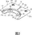
图2是示出用于相互电连接上述电池模块中的邻接的各2个的圆筒形电池的电池间连接板的立体图。FIG. 2 is a perspective view showing an inter-battery connection plate for electrically connecting two adjacent cylindrical batteries in the battery module to each other.
图3A是示出使用上述电池间连接板相互电连接了邻接的2个圆筒形电池的电池间连接结构的立体图,图3B是沿着图3A的A-A线切断的放大剖面图。3A is a perspective view showing a battery connection structure in which two adjacent cylindrical batteries are electrically connected to each other using the above-mentioned battery connecting plate, and FIG. 3B is an enlarged cross-sectional view taken along line A-A of FIG. 3A .
图4A~图4B是分别示出在构成上述的电池模块之前预先实施的向圆筒形电池安装电池间连接板的方式的立体图。FIGS. 4A to 4B are perspective views each showing a manner of attaching an inter-battery connecting plate to a cylindrical battery that is carried out in advance before the above-mentioned battery module is constructed.
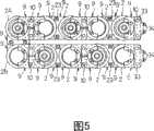
图5是仅示出了上述的电池模块中的全部圆筒形电池的连接状态的正视图。FIG. 5 is a front view showing only the connection state of all the cylindrical batteries in the above-mentioned battery module.
图6是用于说明上述电池模块的组装过程的概略分解正视图。Fig. 6 is a schematic exploded front view for explaining the assembly process of the battery module.
图7是从电池模块的外方侧仅看上述电池模块中的保持框的立体图。7 is a perspective view of only the holding frame in the battery module seen from the outer side of the battery module.
图8是从电池模块的里侧看上述保持框的立体图。Fig. 8 is a perspective view of the holding frame seen from the back side of the battery module.
图9是切断了一部分上述保持框的立体图。Fig. 9 is a perspective view with a part of the holding frame cut away.
图10是上述电池模块的正视图。Fig. 10 is a front view of the above battery module.
图11是上述电池模块的平面图。Fig. 11 is a plan view of the above battery module.
图12是示出本发明的其他例子的保持框的结构的平面图。Fig. 12 is a plan view showing the structure of a holding frame of another example of the present invention.
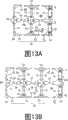
图13A是示出在上述保持框中使用了1个内框部件的结构的平面图,图13B是示出使用了2个内框部件的结构的平面图。FIG. 13A is a plan view showing a structure using one inner frame member for the holding frame, and FIG. 13B is a plan view showing a structure using two inner frame members.
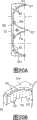
图14是示出了结合本发明的保持框的一例的图。Fig. 14 is a diagram showing an example of a holding frame incorporating the present invention.
图15是示出了结合本发明的保持框的另外的例子的图。Fig. 15 is a diagram showing another example of a holding frame incorporating the present invention.
图16是示出设置了多边形的保持承受部的外框部件的结构的平面图。16 is a plan view showing the structure of an outer frame member provided with a polygonal holding receiving portion.
图17是示出设有由圆弧部分和直角部分组合成的保持承受部的外框部件的结构的平面图。17 is a plan view showing the structure of an outer frame member provided with a holding receiving portion composed of a circular arc portion and a right angle portion.
图18是示出设置了具有切口的保持承受部的外框部件的结构的平面图。Fig. 18 is a plan view showing the structure of an outer frame member provided with a holding receiving portion having a cutout.
图19是示出设置了台阶状的保持承受部的外框部件的结构的平面图。FIG. 19 is a plan view showing the structure of an outer frame member provided with stepped holding receiving portions.
图20A~图20B示出设置了具有空孔部和通风路的保持承受部的外框部件的结构,图20A是平面图,图20B是主要部分的放大图。20A to 20B show the structure of an outer frame member provided with a holding receiving portion having a hollow portion and a ventilation path, FIG. 20A is a plan view, and FIG. 20B is an enlarged view of a main part.
图21是示出设置了梳齿状的保持承受部的外框部件的结构的平面图。Fig. 21 is a plan view showing the structure of an outer frame member provided with comb-shaped holding receiving portions.
图22是示出在保持承受部中具有许多突起的外框部件的结构的主要部分放大图。FIG. 22 is an enlarged view of main parts showing the structure of the outer frame member having many protrusions in the holding receiving portion.
图23是示出本发明的另外例子中的保持框的结构的平面图。Fig. 23 is a plan view showing the structure of a holding frame in another example of the present invention.
图24是示出本发明的另外的例子中的外框部件的结构的平面图。Fig. 24 is a plan view showing the structure of an outer frame member in another example of the present invention.
图25A是示出使用了上述的外框部件和平板状的外框部件的保持框的结构的平面图,图25B是示出使用了上述的外框部件和平板状的外框部件及保持承受部的两端部伸出至单电池的大致外周尺寸的形状的内框部件的保持框的结构的平面图。25A is a plan view showing the structure of a holding frame using the above-mentioned outer frame member and a flat outer frame member, and FIG. 25B is a plan view showing a structure using the above-mentioned outer frame member, a flat outer frame member, and a holding receiving portion. It is a plan view of the structure of the holding frame of the inner frame member whose both ends protrude to the substantially outer peripheral dimension of a battery cell.
图26是示出在上述的外框部件和/或内框部件的保持承受部中设置了用于固定单电池的固定部的结构的平面图。26 is a plan view showing a structure in which a fixing portion for fixing a battery cell is provided in the holding receiving portion of the outer frame member and/or the inner frame member described above.
具体实施方式Detailed ways
以下,参照附图,详细说明本发明的最佳实施方式。图1是示出本发明的一个实施方式的电池模块1的外观图像的概略立体图。该电池模块1如下构成:分上下2段配置电池串,所述电池串是将10个圆筒形电池2按照沿着电池轴向平行的配置并列配置了5个而成的;分别用保持框3固定保持该总计10个圆筒形电池2的电池轴向的两端部。此外,该电池模块1中,10个圆筒形电池2除了各自的两端部以外的外表面露在外部的状态下相连接,因此与现有的在电池收纳部中分别收纳圆筒形电池的结构相比,格外提高散热效果。Hereinafter, best embodiments of the present invention will be described in detail with reference to the drawings. FIG. 1 is a schematic perspective view showing an appearance image of a
此外,在本实施方式中例示了作为圆筒形电池2,使用像具有100Ah左右的大容量和1.6Kg左右的比较大的重量的镍氢蓄电池这样的大型圆筒形电池2的情况,该电池模块1即使是如上所述的大型圆筒形电池2,也能高生产率且高效地进行组装,并且能够成为具有充分的牢固性的结构。关于这以后详细叙述。In addition, in this embodiment, the case where a large
通过相互组合内框部件4和配置在它上下的第一和第二外框部件7、8并可自由装卸地固定,将图1的前后位置上的一对保持框3作为整体而一体化为具有矩形外形的长方体。内框部件4和第一、第二外框部件7、8都是由合成树脂制成的一体成型品,但也可以是考虑了散热性的由铝制成的一体成型品,此外,配置在前后的一对保持框3都相同。但是,该一对保持框3按照相互朝相反方向并且上下位置翻转的相对位置相互平行地配置。通过在重合了一个个固定着的电池间连接板9的一部分的状态下,利用螺栓10与螺母(未图示)的螺合紧固连结,将在电池串方向上邻接的各2个圆筒形电池2相互电连接。图1中示出的电池模块1是保持10个圆筒形电池2的结构的一例,但若这样使用本发明的保持框3,就不需要制作用于保持10个圆筒形电池2的专用的保持框,通过自由组合第一外框部件7、第二外框部件8和内框部件4,能够构成对于各种使用者和用途具有不同的各种形状的电池模块,得到能够适时地解决各种要求的通用性非常好的效果。以下,关于该电池模块1的详细情况依次进行说明。By combining the
图2是示出上述电池间连接板9的立体图,该电池间连接板9仅具有一种相同的形状。即,利用相同的电池间连接板9相互电连接全部的邻接的各2个圆筒形电池2。该电池间连接板9具有通过台阶部13一体地连接了用焊接手段固定在后述的电池外壳上的焊接部11和从该焊接部11伸出的连接部12的形状,焊接部11成为相对于连接部12凹下去台阶部13的凹地。FIG. 2 is a perspective view showing the above-mentioned
图3A是示出使用上述电池间连接板9相互电连接了邻接的各2个圆筒形电池2,并且机械性地连结了的电池间连接结构的立体图,图3B分别示出沿着图3A的A-A线切断的放大剖面图,参照图3A~3B补充说明上述电池间连接板9的形状。上述焊接部11具有在圆筒形电池2的电池壳体14中的圆形端面内包含的半圆弧形的形状。具体地说,具有用半圆形的内周部11a和半圆形的外周部11b围成的半圆弧的形状,所述内周部11a具有比形成了圆筒形电池2的圆形的电极端子板17的周端面稍微大一些的曲率半径,所述外周部11b具有与电池壳体14中的开口端侧的圆形的铆接部18的内周面相对应的曲率半径。在该焊接部11上设置了多个(在该实施方式中是4个)点焊接用的凸点19,并在邻接的各2个凸点19之间的部位形成有缝隙20。FIG. 3A is a perspective view showing a connection structure between two adjacent
上述连接部12大致形成为矩形,具有一对侧边12a、12b和与该侧边12a、12b正交的端边12c,一对侧边12a、12b大于焊接部11的两端部间的距离,并且以比电池壳体14的直径稍微小一些的间隔从焊接部11相互平行地伸出。在该连接部12中形成了从端边12c的中央部向两侧边12a、12b平行延伸的缝隙21,同时在端边12c的两端部附近部位形成了一对连结用孔22。再有,如图2所示,在连接部12中有时也预先用焊接在其下表面侧在与连结用孔22一致的位置上固定一对螺母23。The connecting
上述台阶部13是从焊接部11的半圆形的外面部11b立起的俯视的半圆弧形,将连接部12侧的外侧面形成为与电池壳体14的开口端部的铆接部18中的内侧周面一致的曲率半径的半圆弧形,并且具有比圆筒形电池2的从封口板24到铆接部18的轴向端部的距离稍微大一些的高度。将在铁或铜的至少单面上表面加工了镍的素材或者镍、铁、铜作为素材素材,一体形成具有通过台阶部13一体地连接了焊接部11和连接部12的形状的电池间连接板9,并设定为低电阻。The above-mentioned
再有,成为本实施方式的电池模块1的连接对象的圆筒形电池2是如上所述的大容量且大型的镍氢蓄电池,接着,参照图3B,关于该圆筒形电池2的概略结构进行说明。该圆筒形电池2利用封口体32闭塞兼作负极的有底圆筒形的电池壳体14的一端开口部,该封口体32包括:封口板24、与该封口板24的外面接合的电极端子板17、固定在该电极端子板17的中央部的断面U字形状的间隙状正极端子29、以及配置在该间隙状正极端子29和电极端子板17之间的空间内的橡胶阀体30和绝缘密封垫31。Furthermore, the
上述封口板24的周缘部和电池壳体14的开口端部,通过在它们之间设置绝缘密封垫31的状态下对电池壳体14的开口端部实施向内侧缩径的铆加工形成铆接部18,通过利用该铆接部18压缩的绝缘密封垫31,在相互气密状态下密封固定上述封口板24的周缘部和电池壳体14的开口端部。电池间连接板9通过以盖住铆接部18的状态安装的绝缘环27的存在,不会导致电池壳体14和封口板24电短路。由于焊接部11具有包含在电池壳体14中的圆形端面内的半圆弧形的形状,因此,能够与接合了圆筒形电池2中的正极端子即间隙状正极端子29的封口板24和成为负极端子的电池壳体14的底面28两者共通地安装上述电池间连接板9。The peripheral portion of the sealing
在圆筒形电池2的封口板24上焊接焊接部11来安装电池间连接板9时,将焊接部11载置在圆筒形电池2的封口板24上后,将台阶部13的外侧面一贴在绝缘环27的内侧周面上,就将台阶部13的外侧面形成为与绝缘环27的内侧周面大致一致的曲率半径的半圆弧形,因此,在对于绝缘环27的内侧周面大致嵌合的状态下密封定位了台阶部13的外侧面,因此,能够在稳定地保持了电池间连接板9的状态下将焊接部11焊接在封口板24上。因此,能够在相互焊接的焊接部11和封口板24之间得到总不散乱而且具有高焊接强度的牢固性高的接合状态。When installing the
在上述焊接时,使焊接电极分别与焊接部11中的与一对凸点19相对应的部位抵接而进行凸焊。这样,焊接电流就局部集中地流向因为接触面积小所以接触电阻大的凸点19与封口板24的接触部分,利用其发出的热量,凸点19熔融后相互接合焊接部11和封口板24。这时,焊接部11的缝隙20降低凸焊时的无效电流,同时由于存在缝隙20而能够容易使封口板24与焊接部11的变形而吸收,因此能够进行可靠的焊接。During the above welding, projection welding is performed by bringing welding electrodes into contact with portions corresponding to the pair of
另一方面,在向圆筒形电池2的电池壳体14的底面28焊接安装电池间连接板9时,将焊接部11贴在圆筒形电池2中的电池壳体14的底面28上,在分别使焊接电极与焊接部11中的与一对凸点19相对应的部位抵接的状态下进行凸焊。这样,焊接电流就局部集中地流向因为接触面积小所以接触电阻大的凸点19与底面28的接触部分,利用其发出的热量,凸点19熔融后相互接合焊接部11和底面28。这时,焊接部11的缝隙20降低凸焊时的无效电流,并且由于存在缝隙20而能够容易使焊接部11和底面28通过变形吸收相互不同的变形,因此能够进行可靠的焊接。On the other hand, when attaching the
然后,如图3A~3B所示,在沿着电池轴向平行配置2个圆筒形电池2来将它们在径向上电气性地串联的情况下,使从2片电池间连接板9中的电池壳体14的开口端侧和底面28分别向径向外方突出的各连接部12相互向着相反方向重合配置,定位在使插通图示的螺栓10的各个一对的连结用孔(未图示)一致的相对配置的位置上,通过将从重合状态的各2个连结用孔的一方插通的螺栓10与另一侧的螺母23螺合紧固,将上述2片的电池间连接板9连接成相互电连接的状态。在该连接时,由于存在各个缝隙21而能够容易通过变形吸收双方的电池间连接板9的相互不同的变形,因此能够进行准确的焊接。再有,该电池间连接结构与电池壳体14的正极侧的封口板24和底面28都共通地安装相同的电池间连接板9,但若预先在向电池壳体14的底面28安装用的电池间连接板9的一个面上,利用焊接在与连结用孔一致的位置上固定螺母23,则能够更容易且迅速地进行上述连结操作。Then, as shown in FIGS. 3A to 3B , when two
在用于构成图1的电池模块1的各圆筒形电池2中,在制造之前,预先利用焊接在图4A~4B中分别示出的安装状态下安装电池间连接板9。在如图1所示构成串联了10个圆筒形电池2的电池模块1的情况下,在该10个中的8个圆筒形电池2上,如图4A所示,按照它们的连接部12向着相互相反的方向突出的配置,分别利用焊接,与电池壳体14的正极侧的封口板24和底面28接合一对电池间连接板9。在剩余的2个圆筒形电池2中,分别如图4B中用实线和双点划线所示,按照它们的连接部12分别向着不同的正交方向突出的2种配置中,分别利用焊接预先与电池壳体14的正极侧的封口板24和底面28接合一对电池间连接板9。再有,在该实施方式中,按照与连结用孔22一致的配置,预先利用焊接将螺母23固定在与电池壳体14的底面28即负极端子连接的电池间连接板9上。In each of the
图5仅示出了图1的电池模块1中的10个圆筒形电池2的连接状态。除了位于该图的左端上下的2个圆筒形电池2A、2B以外的8个圆筒形电池2,都预先按照图4A的配置固定了一对电池间连接板9,对于在图前方和后方分别邻接的各2个圆筒形电池2,按照图3中说明的电池间连接结构相互电连接。左端上部的圆筒形电池2A在图4B中的用双点划线示出的配置中预先固定了一对电池间连接板9,并且左端下部的圆筒形电池2B在图4B中用实线示出的配置中预先固定了一对电池间连接板9,该左端上下的圆筒形电池2A、2B在图的后方通过各个电池间连接板9相互电连接。这样,10个圆筒形电池2、2A、2B被串联,在位于该串联的两端部中的图右端上下的圆筒形电池2中,利用螺栓10,在各个图的前方固定的电池间连接板9的连接部12上安装了外部连接用端子板33。在外部连接用端子板33上设置了端子螺丝34。FIG. 5 shows only the connection state of the ten
接着,关于图1的电池模块1的组装工序进行说明。图6是用于说明电池模块1的组装步骤的概略分解正视图,该图中例示了按照从上下翻转了图1的电池模块1的状态即图1的状态开始,绕圆筒形电池2的铅直轴旋转后左右相互调换的配置进行组装的情况。此外,在图6的前后位置上配置组装同样的由内框部件4和第一、第二外框部件7、8构成的保持框3。但是,通过使图示的前面侧的保持框3绕左右方向的水平轴旋转后上下翻转,使得将后方侧的保持框3设置成相对于前方侧的保持框3朝向相反。Next, an assembly process of the
首先,在组装用基台37中的图的前方侧分别载置第一外框部件7,在图的后方侧载置第二外框部件8,将这些外框部件7、8中设置的各3个的螺纹孔7a、8a定位成与组装用基台37的安装孔37a一致之后,使螺栓38插通各安装孔37a而与螺纹孔7a、8a螺合。这样,就在组装用基台37的前方侧和后方侧,按照规定的相对配置即按规定的间隔平行对置的定位状态下,临时固定第一外框部件7和第二外框部件8。First, the first
接着,在处于临时固定在组装用基台37上的前后位置上的第一和第二外框部件7、8上的各个上边中分别每5个形成一个切口状的半圆弧状的保持承受部7b、8b中,在从上方落入的状态下嵌入圆筒形电池2、2A的电池轴向的两端部。这时,按照从图5的图示状态开始绕左右方向的轴旋转后上下翻转的配置,嵌入5个圆筒形电池2、2A。这样,5个圆筒形电池2、2A就在跨架在处于前方侧的第一外框部件7的保持承受部7b和处于后方侧的第二外框部件8中的保持承受部8b上的状态下,嵌入并被支承各电池轴向的两端部。上述保持承受部7b、8b形成为具有与圆筒形电池2、2A的外形相对应的曲率半径的半圆弧形,圆筒形电池2、2A的两端部的半部保持在与保持承受部7b、8b嵌合的状态。Next, in each of the upper sides of the first and second
接着,分别在前后的第一和第二外框部件7、8上盖上内框部件4,使各圆筒形电池2、2A的半部嵌入到在内框部件4的下方的一条边侧形成为切口状的半圆弧形的保持承受部4a内。该保持承受部4a形成为具有与圆筒形电池2、2A的外形相对应的曲率半径的半圆弧形,内框部件4的两端部的外端面4b和它里面的内端面4c分别与处于第一和第二外框部件7、8的两端部中的外端面7c、8c和它里面的内端面7d、8d抵接。从而,以用第一和第二外框部件7、8的保持承受部7b、8b和内框部件4的保持承受部4a从上下夹入电池轴向的两端部的外周面全周的状态,保持5个圆筒形电池2、2A。Next, cover the
接着,将利用内框部件4和第一、第二外框部件7、8保持着电池轴向的两端部的5个圆筒形电池2、2A,定位成分别固定在圆筒形电池2、2A的邻接的各2个上的电池间连接板9中的连接部12的连结用孔22相互一致。在该定位状态中,如箭头所示分别从上方向前后的内框部件4中的在保持承受部4a的中央部贯通的5个圆筒形电池用固定孔4d插入固定用橡胶栓40。该各固定用橡胶栓40的下端与圆筒形电池2、2A的外表面抵接。再有,固定用橡胶栓40具有比圆筒形电池用固定孔4d稍微长一些的尺寸,在插入状态中从圆筒形电池用固定孔4d的图的上端开口稍微突出一些。Next, the five
如上所述,在重合了邻接的各2个的圆筒形电池2、2A的电池间连接板9中的连接部12的状态下,通过连结用孔22,利用螺栓10与螺母23的螺合紧固相互连接5个圆筒形电池2、2A。这样,下段5个的圆筒形电池2、2A就串联构成第一电池串。但是,将固定在处于图6右端的圆筒形电池2A的后方侧上的电池间连接板9设置成其连接部12向上方突出,这时不与其他的电池间连接板9连接。由于在连结各2片的电池间连接板9时,按照螺母23与连结用孔22一致的配置,预先固定在靠近重合的2个连接部12中的圆筒形电池2、2A即内侧的连接部12上,因此,只要将螺栓10插通到重合状态的2个连结用孔22中并与螺母23螺合就可以,能用容易的操作迅速地进行。As described above, in the state in which the
另外,将前后各4根固定螺丝39,从组装用基台37的前后的各插通孔37b,通过处于前方侧的第一外框部件7中的插通孔7e和处于后方侧的第二外框部件8中的插通孔8e,分别与内框部件4的下方侧的各螺纹孔4e螺合紧固,并分别相互连结前方侧的第一外框部件7与内框部件4和后方侧的第二外框部件8与内框部件4。这样,5个圆筒形电池2、2A就利用一体化的内框部件4与第一外框部件7和第二外框部件8分别牢固地固定了电池轴向的两端部。换言之,在将第一和第二外框部件7、8的保持承受部7b、8b与内框部件4的保持承受部4a分别无间隙地贯通于合体形成的保持孔内的状态下,保持5个圆筒形电池2、2A的两端部。In addition, the front and rear four fixing
接着,按照从图5的图示状态开始绕左右方向的水平轴旋转而上下翻转的配置,将上段5个圆筒形电池2、2B嵌入到在前后的各内框部件4的上方的其他边上形成的半圆弧形的保持承受部4a中。上述内框部件4的保持承受部4a形成为具有与圆筒形电池2、2A的外形相对应的曲率半径的半圆弧形。因此,5个圆筒形电池2、2B的各个电池轴向的两端部几乎无间隙地嵌入到前方侧和后方侧的内框部件4的保持承受部4a中,跨架在前后的保持承受部4a上。Next, from the state shown in FIG. 5 , the five
接着,分别在前后的内框部件4上盖上第二和第一外框部件8、7,使各圆筒形电池2、2A的上半部嵌入到在第二和第一外框部件8、7中形成的半圆弧形的保持承受部8b、7b内。该保持承受部8b、7b也形成为具有与圆筒形电池2、2B的外形相对应的曲率半径的半圆弧形,处于第二和第一外框部件8、7中的两端部的外端面8c、7c和它们里面的内端面8d、7d,分别与内框部件4的两端部的外端面4b和它里面的内端面4c抵接。从而,在利用第二和第一外框部件8、7的保持承受部8b、7b和内框部件4的保持承受部4a,从上下无间隙地夹入电池轴向的两端部的外周面全周的状态下,保持5个圆筒形电池2、2B。Then, cover the second and first
接着,将上段5个圆筒形电池2、2B定位为,在它们的电池串方向上邻接的各2个中分别固定着的电池间连接板9中的连接部12的连结用孔22相互一致。通过从内框部件4的各圆筒形电池用固定孔4d的上端开口稍微突出一些的固定用橡胶栓40与自身的外表面抵接,顶住该定位后的各圆筒形电池2、2B,保持在电池间连接板9中的连接部12的连结用孔22相互一致的定位状态。Next, the upper five
在如上所述顶住了上段5个圆筒形电池2、2B的保持状态下,利用插通到连通孔22中的螺栓10与螺母23的螺合紧固,相互连接处于电池串方向上邻接的各2个圆筒形电池2、2B的电池间连接板9中的各个连接部12,并且利用螺栓10和螺母23的螺合紧固,相互连接右端的圆筒形电池2B和它下方的圆筒形电池2A的各个连接部12。这样,就全部串联10个圆筒形电池2、2A、2B。在连结上述各2片的电池间连接板9时,由于按照螺母23与连结用孔22一致的配置,将螺母23预先固定在重合的2个连接部12中的靠近圆筒形电池2、2A的连接部12,因此,只要将螺栓10插通到重合状态的2个连结用孔22中来与螺母23螺合就可以,能用容易的操作迅速地进行。In the holding state of the five
最后,将与下方图示同样的固定螺丝39,通过处于前方侧的第二外框部件8中的插通孔8e和处于后方侧的第一外框部件7中的插通孔7e,分别与内框部件4的上方侧的螺纹孔4f螺合紧固,分别相互连结前方侧的第二外框部件8与内框部件4、以及后方侧的第一外框部件7与内框部件4。这样,上段的5个圆筒形电池2、2B就利用一体化的内框部件4与第二外框部件8和第一外框部件7分别牢固地保持着电池轴向的两端部,形成第二电池串,完成了图1的电池模块1的组装。Finally, the same fixing screws 39 as shown below are passed through the
在该组装完成后的电池模块1中,利用上下的固定螺丝39的紧固,5个固定用橡胶栓40从上下受到圆筒形电池2、2A、2B的压力而压缩的状态下,被压入到圆筒形电池用固定孔4d内,起到用其复原力压接在上下的圆筒形电池2、2A、2B上,不松动地保持圆筒形电池2、2A、2B的功能。最后,拔掉螺栓38卸下组装用基台37。In the assembled
本实施方式的电池模块1通过经过如上所述的工序进行组装,即使在使用上述的1.6kg左右的具有比较大重量的圆筒形电池2作为单电池的情况下,也能够容易且效率地组装。即,由于保持框3是三分为内框部件4和第一、第二外框部件7、8的结构,因此,能够将全部的圆筒形电池2一个个地从上方以落入的状态插入到各框部4、7、8的保持承受部4a、7b、8b内来进行组装。从而,与像现有的电池模块那样需要将各圆筒形电池一个个地插入到电池收纳部中或者将在电池轴向上电气性串联了多个圆筒形电池2的电池串插通到贯通孔中的工序不同,即使是大型的圆筒形电池2,也能够容易将其装入到保持框3的规定地方中来保持。The
此外,能够利用螺栓10和螺母23的螺合紧固,相互电连接且机械性连结已预先固定在已设置在了保持框3中的各圆筒形电池2上的电池间连接板9。因此,不需要像现有的电池模块这样用于电连接已装入支架箱等中的圆筒形电池2的焊接工序,由于削减了该焊接工序,因此即使在将大型的圆筒形电池2作为结构要素的情况下,也能容易且高效地相互连接进行组装。In addition, the inter-battery connecting
另外,在组装电池模块1时,由于首先将配置在前后位置的最下位上的第一和第二外框部件7、8临时固定在组装用基台37上后定位,因此,能够稳定且准确地进行大型圆筒形电池2的装入。In addition, when assembling the
另一方面,在利用保持框3固定位于圆筒形电池2的各个电池轴向上的两端部时,由于使各框部4、7、8中形成的半圆弧形的保持承受部4a、7b、8b中的各2个相对于圆筒形电池2的外周面从两侧夹入进行嵌合,因此,能够将半圆弧形的保持承受部4a、7b、8b设定为具有与圆筒形电池2的外形相对应的曲率半径的半圆弧形。即,在像现有的电池模块这样使圆筒形电池2插通到贯通孔中的结构中,必须要设定贯通孔的直径比圆筒形电池2的直径稍微大一些,设置用于容易插通的空间,但本实施方式与其不同,能够设定通过各2个的半圆弧形的保持承受部4a、7b、8b合体形成的贯通孔与圆筒形电池2的外径大致相同。因此,在该电池模块1中,即使是大型的圆筒形电池2,也能够用长方体的保持框3不松动而且牢固固定、且总是稳定地保持该各圆筒形电池2的电池轴向的两端部,成为具有高牢固性的结构。On the other hand, when using the holding
此外,在内框部件4的圆筒形电池用固定孔4d内压缩着的固定用橡胶栓40的作用在于,利用其复原力与上下相对的各2个的圆筒形电池2的外表面压接,吸收受到了振动和冲击时的外力。因此,更进一步不摇晃而且稳定地保持各圆筒形电池2。In addition, the role of the fixing
另外,上述电池模块1在维护等时认为一部分的圆筒形电池2已消耗或劣化的情况下,只要拔掉各固定螺丝39,就能够简单地将保持框3分解为内框部件4和第一、第二外框部件7、8,同时通过拆下电池间连接板9上的螺栓10,就能够卸下各个圆筒形电池2,因此,能够仅交换必要的圆筒形电池2。因此,该电池模块1与像现有技术那样即使一部分电池消耗或劣化了也要交换电池模块全体的情况相比,具有能够大幅度地降低运行成本的突出的优点。In addition, in the above-mentioned
接着,关于上述电池模块1的详细部分进行说明。图7至图9都仅示出了组装状态的保持框3,图7是从前方侧看上述电池模块1中的前方侧的保持框3的立体图,示出了保持框3的电池模块1中的外表面侧,图8是从前方侧看上述电池模块1中的后方侧的保持框3的立体图,示出了保持框3的电池模块1中的内表面侧,图9是切断一部分的立体图。Next, details of the
如图8所示,内框部件4和第一、第二外框部件7、8的内表面侧在各保持承受部4a、7b、8b的周围的地方形成为凹地,仅通过这些凹地形成为用于作为成型部件的缺失部分,在功能上与将除了各保持承受部4a、7b、8b以外的地方形成为平面的情况相同。As shown in FIG. 8, the inner surface sides of the
另一方面,如图7和图9所示,内框部件4和第一、第二外框部件7、8的外表面侧形成为除了这些各框部4、7、8的保持承受部4a、7b、8b中的半圆弧形的中央部以外的部分从外表面向里凹下了规定的台阶d1的凹地N,同时,在图的左右方向中相互邻接的各2个的保持承受部4a、7b、8b中,在从外表面向里凹下了比上述台阶d1小的台阶d2的位置上,利用向各保持承受部4a、7b、8b的排列方向平行延伸的直线状的上下一对的导向支承部41进行连接。此外,内框部件4中的图7的左端(在图9中是右端)上下相对的2个保持承受部4a、4a间,在从外表面向里凹下了上述台阶d2的位置上,利用在上下方向上延伸的直线状的导向支承部42进行连接。On the other hand, as shown in FIG. 7 and FIG. 9, the outer surface sides of the
将图7的左端的左右方向中相对的导向支承部42与内框部件4的保持立壁部43的对面距离部分R设定为与图2中说明的电池间连接板9中的连接部12的一对侧边12a、12b间的宽度大致相同。The facing distance part R between the
从而,在利用上述保持框3固定10个圆筒形电池2时,将邻接的各2个的圆筒形电池2上固定的电池间连接板9的连接部12嵌入到上下相对的一对导向支承部41之间,同时,将图7的左端的上下邻接的2个圆筒形电池2上固定的电池间连接板9的连接部12嵌入到在上下方向上延伸的导向支承部42与保持立壁部43之间。Therefore, when using the above-mentioned
将导向支承部41、42的距外表面的台阶d2设定为比处于2片电池间连接板9中的各个厚度和螺栓10的螺纹部的高度的总和稍微大一些。此外,将台阶d1和台阶d2的差(d1-d2)设定为比从螺合螺栓10的螺母23超出的螺纹部的高度稍微大一些。这样,如图1的电池模块1的平面图即图11所示,各电池间连接板9、螺栓10和螺母23就包含在保持框3内,全部不突出在外。因此,在该电池模块1中,不需要特别设置用于防止各圆筒形电池2间的电气短路的绝缘装置。The steps d2 from the outer surface of the
另外,如上述电池模块1的正视图即图10所示,在与插通孔7e、8e连通的收纳凹地7f、8f内收纳着相互固定内框部件4和第一、第二外框部件7、8的固定螺丝39的螺纹部。因此,在使用规定个数的该电池模块1构成电池包时,各电池间连接板9、螺栓10和螺母23包含在保持框3内,不存在任何从长方体的一对保持框3突出的部件,因此,通过按照纵横排列了多个电池模块1的组合相互固定,能够容易构成。In addition, as shown in FIG. 10 which is a front view of the above-mentioned
此外,作为电池模块1,由于各电池间连接板9嵌入到上下相对的一对导向支承部41之间和导向支承部42与保持立壁部43之间而被限制位置,因此,成为牢固性更高的结构,适合于使用大型的圆筒形电池2作为单电池的情况。并且,在组装时,能够相互重合邻接的各2片的电池间连接板9的连接部12,在使其与各个连结用孔22一致的定位状态下进一步可靠地保持,将螺栓10与螺母23螺合紧固时的操作性提高。In addition, as the
如图10所示,在前方侧的保持框3中,没有使用左右方向上每隔一个的导向支承部41和导向支承部42及保持立壁部43作为电池间连接板9的支承用。另一方面,在按照使前方侧的保持框3绕圆筒形电池2的轴旋转的配置设置的后方侧的保持框3中,使用了在左右方向中的前方侧不使用的导向支承部41、42和保持立壁部43作为电池间连接板9的支承用。即,在保持框3的外侧面,在左右方向中邻接的各2个保持承受部4a、7b、8b间全部形成了导向支承部41,并且在左端的上下方向上邻接的保持承受部4a、4a间形成了导向支承部42和保持立壁部43,因此,能够前后双方共用同一形状的保持框3。在此,根据按照图5所示的连接状态连接10个圆筒形电池2的关系,产生如上所述地未使用的保持承受部4a或者导向支承部42和保持立壁部43,但在作为保持框3的功能上没有任何问题。As shown in FIG. 10 , in the holding
再有,在上述实施方式中,作为图6中示出的两外框部件7、8的各个内端面7d、8d与内框部件4的内端面4c相互抵接的结构,例示说明了利用对应的各2个半圆弧形保持承受部7b、4a、8b、4a形成与圆筒形电池2的外形相对应的圆形的贯通孔的情况,但所述内框部件4和两外框部件7、8,也可以构成为仅各个外端面4b、7c、8c彼此之间抵接,设定各个内端面4c、7d、8d比图示短,在它们之间产生间隙的结构。该情况下,在螺合紧固固定螺丝39时,使各框部4、7、8稍微弹性变形,就能够使各保持承受部4a、7b、8b与圆筒形电池2的外周面紧密接触,能够更进一步牢固地保持圆筒形电池。Furthermore, in the above-mentioned embodiment, as the structure in which the respective inner end faces 7d, 8d of the two
下面,参照图12~图26,关于本发明的保持框的其他结构例和保持承受部的其他形状例进行说明。Next, other structural examples of the holding frame and other shape examples of the holding receiving portion of the present invention will be described with reference to FIGS. 12 to 26 .
图12是示出本发明的其他例子中的保持框50的结构的平面图。保持框50由外框部件51和外框部件52构成,各个外框部件51、52分别具有与圆筒形电池2的外周面抵接的保持承受部71、72。这些保持承受部71、72形成为分别具有与圆筒形电池2的外周面的大致半周相对应的曲率半径的半圆弧形,在结合外框部件51、52构成了保持框50时,在保持承受部71、72中几乎无间隙地嵌入圆筒形电池2的外周面。此外,在外框部件51中的与外框部件52的结合部分中设置了配合凸部67,使得外框部件51和外框部件52不偏移地结合,在外框部件52中的与外框部件51的结合部分设置了与配合凸部67相对应的形状的配合凹部68。FIG. 12 is a plan view showing the structure of a holding
图13A~图13B是除了上述的外框部件51、52之外组合了内框部件53来构成的保持框50的结构的平面图。在内框部件53的两面形成了具有与圆筒形电池2的外周面的大致半周相对应的曲率半径的半圆弧形保持承受部73,在内框部件53的一个面侧设置着结合用的配合凸部67,在另一个面侧设置着与配合凸部67相对应的形状的配合凹部68,因此,能够适当地选择是如图13A所示构成结合一个内框部件53和外框部件51、52来能够保持最大4个圆筒形电池2的保持框50,还是如图13B所示构成结合2个内框部件53和外框部件51、52来能够保持最大6个圆筒形电池2的保持框50。再有,不限于图示的例子,也可以自由地构成适当增加内框部件53的数量后能够保持期望的数量的圆筒形电池2的保持框50。13A to 13B are plan views of the structure of a holding
下面,图14中示出使用2个外框部件51、52和1个内框部件53构成保持框50时的结合方法的一例。首先,通过将一个外框部件51的配合凸部67嵌入到内框部件53的配合凹部68中,无偏移地结合了一个外框部件51和内框部件53。接着,通过将内框部件53的配合凸部67嵌入到另一个外框部件52的配合凹部68中,就无偏移地结合了已与一个外框部件51结合的内框部件53和另一个外框部件52。然后,使大致相当于连结后的框部的长度(图的左右方向)的长度的连结体65,与在各框部51、52、53中框部彼此之间连结的方向上延伸的面抵接,将固定螺丝39,通过设置在连结体65的规定地方上的连结孔65a,与设置在外框部件51、52和内框部件53的规定地方上的螺纹孔64螺合紧固,固定保持框50。再有,作为保持框50的固定方法,不仅是在保持框50的任意一侧的面上设置连结体65的方法,也可以是设置在保持框50的两面上,在两面侧用固定螺丝39螺合紧固的方法。此外,为了提高对于弯曲的强度,也可以将连结体65设置成为截面L字形,或者在连结体65上设置加强肋。Next, FIG. 14 shows an example of a joining method when the holding
图15中示出构成保持框50时的结合方法的另外的例子。图15中示出的保持框50由外框部件51g、52g和内框部件53g构成。在沿着这些外框部件51g、52g和内框部件53g的各个侧边的方向邻接的各2个的保持承受部71g、72g、73g之间,不设置配合凸部和配合凹部,取而代之分别设置在框部彼此之间的连结方向上延伸的插通孔61、62、63,在组合了一个外框部件51g和另一个外框部件52g及内框部件53g时,各插通孔61、62、63成为相连的一条插通孔。然后,从图中的箭头示出的方向向连接的插通孔插通滚珠螺杆80,通过用内螺母螺合紧固滚珠螺杆80的尖端,牢固地结合保持框50。此外,也可以是在图15中的插通孔61的尖端设置内螺母(未图示),通过用螺母螺合紧固滚珠螺杆80的尖端来结合保持框50的结构。再有,滚珠螺杆80的长度预先准备多种,通过适当使用与根据内框部件53g的数量相应变化的保持框50的长度(图的左右方向)相应的滚珠螺杆80,能够自由地设定保持期望的数量的圆筒形电池2的保持框50。FIG. 15 shows another example of a coupling method when forming the holding
下面示出保持承受部的各种变形例。图16中示出的外框部件51a是设置了多边形的保持承受部71a的结构。这样,若是设置了与对应于圆筒形电池2的外周面的大致半周的曲率半径大致一致的多边形的保持承受部71a的结构,则由于在保持承受部71a与圆筒形电池2的外周面之间产生了一些间隙,因此,既能够牢固地保持圆筒形电池2,并且能够利用该间隙散发充放电时的热量。此外,由于保持承受部71a是多边形,因此,能够比较灵活地对应于电池外周面的形状偏差来保持。Various modified examples of the holding receiving portion are shown below. The
图17中示出的外框部件51b是设置了保持承受部71b的结构,该保持承受部71b由与对应于圆筒形电池2的外周面的曲率大致半径一致的圆弧部83、和直角部84的组合构成。通过设置这样的保持承受部71b,能不仅保持圆筒形电池2,也能保持方形电池,此外,在保持圆筒形电池2时,保持承受部71b的直角部84起到用于散热的间隙的功能,在保持方形电池时,保持承受部71b的圆弧部83起到用于散热的间隙的功能。The outer frame member 51b shown in FIG. 17 has a structure provided with a holding receiving portion 71b composed of an arc portion 83 corresponding to the approximate radius of curvature of the outer peripheral surface of the
图18中示出的外框部件51c是设置了保持承受部71c的结构,所述保持承受部71c在与对应于圆筒形电池2的外周面的大致半周的曲率半径大致一致的半圆弧形的面上,具有切口81。根据这样的保持承受部71c,在保持了圆筒形电池2时,切口81起到用于散热的间隙的功能。The
图19示出的外框部件51d是具有台阶状的保持承受部71d的结构,连结该各台阶的顶点的线成为半圆弧形,该半圆弧形的曲率半径与对应于圆筒形电池2的外周面的大致半周的曲率半径大致一致。根据这样的台阶状的保持承受部71d,保持了圆筒形电池2时在圆筒形电池2的外周面与各台阶之间形成的间隙,就起到用于散热的间隙的功能。The
图20A~20B中示出的外框部件51e是设置了保持承受部71e的结构,所述保持承受部71e在与对应于圆筒形电池2的外周面的大致半周的曲率半径大致一致的半圆弧形的面上,具有许多空孔部69。该保持承受部71e是由内侧的半圆弧形面和外侧的半圆弧形面构成的双层结构,内侧的半圆弧形面成为与对应于圆筒形电池2的外周面的大致半周的曲率半径大致一致的形状,在内侧的半圆弧形面(保持承受部71e)与外侧的半圆弧形面之间设置了多条通风路82。在与圆筒形电池2的外周面抵接的内侧的半圆弧形面上设置了许多空孔部69,因此,从这些空孔部69通过通风路82散发电池充放电时产生的热量。再有,可以根据电池的散热量适当地设定空孔部69的数量和其排列图形。The
图21中示出的外框部件51f是设置了梳齿状的保持承受部71f的结构,连结各梳齿状的顶点的线成为与对应于圆筒形电池2的外周面的大致半周的曲率半径大致一致的半圆弧形。根据这样的梳齿状的保持承受部71f,既牢固地保持圆筒形电池2,各梳齿间的间隙又能起到用于散热的间隙的功能。再有,上述图示的例子仅关于某一个外框部件的结构进行了说明,但可以将分别与这些各外框部件51a~51f相对应的其他的外框部件和内框部件的保持承受部,设置为与外框部件51a~51f的保持承受部71a~71f相同的形状。The
此外,如图22所示,也可以在外框部件51h的保持承受部71h设置许多突起71i。在图22中示出的外框部件51h中,连结了许多突起71i的各顶部彼此之间的线成为与对应于圆筒形电池2的外周面的曲率半径大致一致的半圆弧形,因此,在用该保持框51h保持了圆筒形电池2时,在圆筒形电池2的外周面与保持承受部71h之间产生对应于这些突起71i的高度的间隙,因此,该间隙就起到用于散发充放电时产生的热量的间隙的功能。再有,突起71h的形状不限于图示的圆形,可以是多种形状。Moreover, as shown in FIG. 22, you may provide many protrusions 71i in the
图23中示出保持框50的另外的结构。图23的保持框50由一个外框部件54和另一个外框部件55构成,所述外框部件54设置了保持承受部74,该保持承受部74具有与对应于圆筒形电池2的外周面的半周以上的曲率半径大致一致的形状,所述外框部件55设置了保持承受部75,该保持承受部75具有与对应于圆筒形电池2的外周面的半周以下的曲率半径大致一致的形状。在结合了一个外框部件54和另一个外框部件55时,相互对置结合的保持承受部74、75形成具有与圆筒形电池2的外周面的全周相对应的曲率半径的圆弧形状。通过在外框部件55中设置的配合凹部68中嵌入外框部件54中设置的配合凸部67,来进行外框部件54、55的结合。根据这样的结构,由于在构成保持框50之前稳定地保持已嵌入到保持承受部74中的圆筒形电池2,因此,不需要另外设置固定装置,该固定装置用于在保持框50的结合工序中固定圆筒形电池2使得其不从规定位置偏移,因此,实现工序的简化和低成本。再有,图23中示出了仅使用了外框部件54、55的保持框50的结构,但不限于此,只要使用在一方侧具有与对应于圆筒形电池2的外周面的半周以下的曲率半径大致一致的形状的保持承受部、在另一方侧具有与对应于圆筒形电池2的外周面的半周以上的曲率半径大致一致的形状的保持承受部的内框部件,就可以根据用途自由地设定能够保持期望数量的圆筒形电池2的保持框50。此外,作为这些外框部件54、55与内框部件的固定方法,可以是图14中示出的利用连结体65的方法,以及图15中示出的利用滚珠螺杆80的方法。A further configuration of the holding
图24~图26中示出保持框50的另外的例子。图24中示出的外框部件56是设置了保持承受部76的结构,所述保持承受部76包括:圆弧状部分,其曲率半径与对应于圆筒形电池2的外周面的大致半周的曲率半径大致一致;和直线部,从该圆弧状部分的两端部伸出至圆筒形电池2的大致外形尺寸。与该外框部件56结合构成保持框50的另一个外框部件57是如图25A所示的平板状。若使用这样形状的外框部件56、57,能够用一个外框部件56保持圆筒形电池2,因此,除了简化另一个外框部件57的结构实现成本的降低之外,还得到操作性提高的效果。此外,如图25B所示,若使用设置了保持承受部78的结构的内框部件58,所述保持承受部78由与对应于圆筒形电池2的外周面的大致半周的曲率半径大致一致的圆弧状部分、和从该圆弧状部分的两端部伸出至圆筒形电池2的大致外形尺寸的直线部构成,就能够根据用途自由地设定能够与外框部件56、57组合保持期望数量的圆筒形电池2的保持框50。此外,如图26所示,若是在外框部件56(内框部件58)的保持承受部76(78)的直线部分中设置了用于保持圆筒形电池2的固定部60的结构,能够利用该固定部60稳定保持圆筒形电池,得到保持框50的结合工序时的操作性提高的效果。再有,作为图24~图26中示出的保持框50的结合方法,除了图14中示出的利用连结体65的方法和图15中示出的利用滚珠螺杆80的方法,也可以是利用粘结剂、热熔敷、热焊接、超声波焊接、封闭弹簧等的多种方法。Another example of the holding
再有,设置在图12~图26的外框部件51、51a~51h、52、54~57和内框部件53、58中的螺纹孔64是用于在使用连结体65结合保持框50时螺合紧固固定螺丝39的螺纹孔,设置在外框部件51、51a~51h、52、54~57中的端子螺纹孔66是用于螺合紧固端子螺丝34的螺纹孔。此外,设置在外框部件51、51a~51h、52、54~57和内框部件53、58的各处的内螺母安装孔70,用于螺合紧固结合电池间连接板9彼此之间的螺栓10。另外,关于图23中示出的外框部件54、55和图24~图26中示出的外框部件56和内框部件58的保持承受部74、75、76、78,可以设置为与如图16~图22所示的各种形状的保持承受部71a~71h相同的形状。Furthermore, the threaded
再有,作为在本实施方式中说明的保持框的素材,可以使用从变性对聚苯乙醚树脂、变性对聚苯氧树脂、ABS树脂、聚醚砜树脂、聚醚酰亚胺树脂、聚酰亚胺树脂、金属材料、或者以聚对苯二甲酸乙二酯为主原料填充复合了玻璃纤维和云母材料的热塑性聚酯系复合材料中选择的至少一种。此外,也可以使用橡胶等由高分子材料构成的有弹性的材料作为素材,但这时期望具有1.5~7.0MPa左右的杨氏模量。In addition, as the material of the holding frame described in this embodiment, denatured p-polyphenylene ether resin, denatured p-polyphenoxy resin, ABS resin, polyethersulfone resin, polyetherimide resin, polyamide resin, etc. can be used. At least one selected from imine resin, metal material, or thermoplastic polyester composite material with polyethylene terephthalate as the main raw material filled with glass fiber and mica material. In addition, an elastic material made of a polymer material such as rubber may be used as a material, but in this case, it is desirable to have a Young's modulus of about 1.5 to 7.0 MPa.
此外,在上述说明中主要说明了使用了圆筒形电池2的结构,但不限于此,也可以使用各种角筒形电池,用具有与其外形尺寸相对应的形状的保持承受部的保持框构成电池模块1。此外,在上述说明中示出了串联了电池模块1内的电池2的例子,但也可以根据用途并联。In addition, in the above description, the structure using the
工业上的可利用性Industrial availability
如以上说明地,本发明的电池模块由于除了各单电池中的用保持框保持的两端部以外的外表面都露出在外部,因此,能够得到格外高的散热效果,此外,通过构成为将保持框三分为内框部件和2个外框部件,即使是大型的单电池,也能够将其容易装入到保持框的规定地方上,并且,由于保持框具有自由装卸地连结了内框部件和2个外框部件的结构,因此,能够容易分解后仅替换消耗和劣化了的单电池。此外,在本发明的电池模块的制造方法中,能够高生产率且容易地制造具有上述显著效果的电池模块。As described above, since the battery module of the present invention exposes the outer surfaces of each unit cell except for both ends held by the holding frame, a remarkably high heat dissipation effect can be obtained. The holding frame is divided into three parts, the inner frame part and the two outer frame parts, and even a large single cell can be easily installed in the predetermined place of the holding frame, and the inner frame is connected freely due to the holding frame Parts and two outer frame parts, therefore, it is easy to disassemble and replace only the consumed and deteriorated cells. In addition, in the battery module manufacturing method of the present invention, it is possible to easily manufacture a battery module having the above-mentioned remarkable effects with high productivity.
Claims (29)
Applications Claiming Priority (5)
| Application Number | Priority Date | Filing Date | Title |
|---|---|---|---|
| JP149880/2005 | 2005-05-23 | ||
| JP2005149880 | 2005-05-23 | ||
| JP124089/2006 | 2006-04-27 | ||
| JP2006124089AJP5127154B2 (en) | 2005-05-23 | 2006-04-27 | Battery module |
| PCT/JP2006/309938WO2006126447A1 (en) | 2005-05-23 | 2006-05-18 | Battery module and method of producing the same |
Publications (2)
| Publication Number | Publication Date |
|---|---|
| CN101180749A CN101180749A (en) | 2008-05-14 |
| CN101180749Btrue CN101180749B (en) | 2011-04-13 |
Family
ID=39406079
Family Applications (1)
| Application Number | Title | Priority Date | Filing Date |
|---|---|---|---|
| CN2006800181617AExpired - Fee RelatedCN101180749B (en) | 2005-05-23 | 2006-05-18 | Battery module and manufacturing method thereof |
Country Status (2)
| Country | Link |
|---|---|
| JP (2) | JP2010177203A (en) |
| CN (1) | CN101180749B (en) |
Families Citing this family (28)
| Publication number | Priority date | Publication date | Assignee | Title |
|---|---|---|---|---|
| EP2259586B1 (en) | 1996-02-28 | 2013-12-11 | Panasonic Corporation | High-resolution optical disk for recording stereoscopic video, optical disk reproducing device and optical disk recording device |
| FR2947958B1 (en)* | 2009-07-08 | 2011-09-09 | Commissariat Energie Atomique | BATTERY OF ACCUMULATORS WITH REDUCED LOSSES |
| DE102009050315B4 (en)* | 2009-10-16 | 2022-12-29 | Elringklinger Ag | Connection device, electrochemical device and method for electrically conductive connection of cell terminals of electrochemical cells of an electrochemical device |
| JP5897551B2 (en)* | 2011-03-31 | 2016-03-30 | 三洋電機株式会社 | Battery pack |
| FR2979472B1 (en)* | 2011-08-29 | 2013-08-23 | Batscap Sa | CONNECTOR ARRANGED BETWEEN TWO ENERGY STORAGE ASSEMBLIES |
| JP2013115221A (en)* | 2011-11-29 | 2013-06-10 | Shin Kobe Electric Mach Co Ltd | Capacitor module |
| JP6246483B2 (en) | 2013-04-04 | 2017-12-13 | 株式会社マキタ | Battery pack for electric tools |
| CN203386824U (en)* | 2013-06-09 | 2014-01-08 | 田军昊 | Safe intelligent battery pack |
| FR3013900B1 (en)* | 2013-11-22 | 2015-12-11 | Blue Solutions | ENERGY STORAGE MODULE COMPRISING A PLURALITY OF ENERGY STORAGE ASSEMBLIES |
| JP6598189B2 (en)* | 2015-03-30 | 2019-10-30 | Fdk株式会社 | Battery support device |
| KR102341402B1 (en) | 2015-05-15 | 2021-12-20 | 삼성에스디아이 주식회사 | Battery module |
| KR102056366B1 (en) | 2015-09-02 | 2019-12-16 | 주식회사 엘지화학 | Cell module for secondary battery pack and assembly method for the same |
| US20190221814A1 (en)* | 2016-09-29 | 2019-07-18 | Panasonic Intellectual Property Management Co., Ltd. | Cell module |
| CN106531438B (en)* | 2016-09-30 | 2019-01-25 | 铜陵其利电子材料有限公司 | A kind of cylindrical capacitor fastening plates |
| CN106531948A (en)* | 2016-10-19 | 2017-03-22 | 广东亿纬赛恩斯新能源系统有限公司 | A battery pack connecting plate welding structure and welding process |
| FR3058576A1 (en)* | 2016-11-07 | 2018-05-11 | Compagnie Generale Des Etablissements Michelin | UNIT MODULE FOR BATTERY PACK, AND BATTERY PACK |
| CN106384799A (en)* | 2016-11-28 | 2017-02-08 | 丁茗 | Cylindrical power battery module box capable of carrying out anode and cathode location |
| DE102016224318A1 (en)* | 2016-12-07 | 2018-06-07 | Audi Ag | memory array |
| KR102317506B1 (en)* | 2017-04-10 | 2021-10-26 | 삼성에스디아이 주식회사 | Battery pack |
| CN107123762A (en)* | 2017-05-27 | 2017-09-01 | 浙江卓远机电科技有限公司 | A kind of battery holder provided with battery core clamping structure |
| CN114122589B (en)* | 2017-12-11 | 2024-01-12 | 宁德时代新能源科技股份有限公司 | Frame and battery module |
| CN109148807A (en)* | 2018-08-13 | 2019-01-04 | 珠海格力电器股份有限公司 | Connecting device and battery module |
| JP7047783B2 (en)* | 2019-01-14 | 2022-04-05 | トヨタ自動車株式会社 | Battery pack |
| JP7369002B2 (en)* | 2019-10-11 | 2023-10-25 | カワサキモータース株式会社 | battery pack |
| KR20230034924A (en)* | 2021-09-03 | 2023-03-10 | 주식회사 엘지에너지솔루션 | Cylindrical secondary battery module and secondary battery pack including the same and vehicle including the same |
| EP4235941A1 (en)* | 2022-02-25 | 2023-08-30 | Molex, LLC | Battery connection module |
| CN116231206A (en)* | 2023-03-21 | 2023-06-06 | 重庆长安新能源汽车科技有限公司 | Battery components, battery pack components and power equipment |
| CN117154349B (en)* | 2023-11-01 | 2024-01-19 | 成都大学 | New energy battery module convenient to change |
Citations (1)
| Publication number | Priority date | Publication date | Assignee | Title |
|---|---|---|---|---|
| CN1592977A (en)* | 2001-11-27 | 2005-03-09 | 松下电器产业株式会社 | Connection structure between batteries, battery module and battery pack |
Family Cites Families (8)
| Publication number | Priority date | Publication date | Assignee | Title |
|---|---|---|---|---|
| JPH10106520A (en)* | 1996-09-26 | 1998-04-24 | Matsushita Electric Ind Co Ltd | Battery power supply |
| JPH1145691A (en)* | 1997-07-28 | 1999-02-16 | Shin Kobe Electric Mach Co Ltd | Battery pack |
| JP4165620B2 (en)* | 1997-09-30 | 2008-10-15 | 富士重工業株式会社 | Automotive battery-equipped equipment |
| JP2000040497A (en)* | 1998-07-23 | 2000-02-08 | Japan Storage Battery Co Ltd | Battery |
| JP4547741B2 (en)* | 1999-10-06 | 2010-09-22 | パナソニック株式会社 | Battery holding device |
| JP2003142059A (en)* | 2001-11-01 | 2003-05-16 | Honda Motor Co Ltd | Battery-powered power supply |
| JP4163419B2 (en)* | 2002-01-23 | 2008-10-08 | 本田技研工業株式会社 | Connection structure of positive electrode and negative electrode in battery assembly |
| JP2005123069A (en)* | 2003-10-17 | 2005-05-12 | Sanyo Electric Co Ltd | Assembled battery |
- 2006
- 2006-05-18CNCN2006800181617Apatent/CN101180749B/ennot_activeExpired - Fee Related
- 2010
- 2010-03-29JPJP2010075880Apatent/JP2010177203A/enactivePending
- 2010-03-29JPJP2010075886Apatent/JP5127864B2/ennot_activeExpired - Fee Related
Patent Citations (1)
| Publication number | Priority date | Publication date | Assignee | Title |
|---|---|---|---|---|
| CN1592977A (en)* | 2001-11-27 | 2005-03-09 | 松下电器产业株式会社 | Connection structure between batteries, battery module and battery pack |
Non-Patent Citations (3)
| Title |
|---|
| JP特开2000-40497A 2000.02.08 |
| JP特开2001-148235A 2001.05.29 |
| JP特开2004-87218A 2004.03.18 |
Also Published As
| Publication number | Publication date |
|---|---|
| JP5127864B2 (en) | 2013-01-23 |
| CN101180749A (en) | 2008-05-14 |
| JP2010177204A (en) | 2010-08-12 |
| JP2010177203A (en) | 2010-08-12 |
Similar Documents
| Publication | Publication Date | Title |
|---|---|---|
| CN101180749B (en) | Battery module and manufacturing method thereof | |
| JP5127154B2 (en) | Battery module | |
| EP1750313B1 (en) | Modular battery with connector interconnecting terminals of adjacent unit cells | |
| US6819081B2 (en) | Power source apparatus | |
| JP5323782B2 (en) | Battery module and battery pack comprising a plurality of battery modules | |
| KR101249110B1 (en) | Inter-cell connectiing structure | |
| CN104412417B (en) | Battery pack | |
| US8764852B2 (en) | Battery pack including an electric harness and method of manufacturing the same | |
| KR101305218B1 (en) | Battery Module Having Fixing Member and Coupling Member, and Battery Pack Employed with the Same | |
| CN105322123A (en) | power storage device | |
| KR101326182B1 (en) | Battery Module Based upon Unit Module Having External Covering Member and Cartridge | |
| KR20130122323A (en) | Battery pack and battery module having the same | |
| CN1592977A (en) | Connection structure between batteries, battery module and battery pack | |
| KR101255542B1 (en) | Battery pack | |
| KR20150055255A (en) | Battery Module and Manufacturing the Same | |
| JP5423067B2 (en) | Battery module and manufacturing method thereof | |
| KR20190053124A (en) | Battery pack of one body busbar for energy storage system | |
| CN115088115A (en) | Battery module, battery pack including the same, vehicle, and method of manufacturing battery pack | |
| CN112771712A (en) | Battery pack and device including the same | |
| KR20190051885A (en) | Battery pack for energy storage system | |
| KR20120074426A (en) | Unit module of novel structure and battery module comprising the same | |
| KR101275811B1 (en) | Battery pack | |
| KR102672157B1 (en) | End Plate for Battery Module | |
| CN119852541A (en) | Traction battery pack assembly method | |
| KR20230001350A (en) | Battery module including coin cells and manufacturing method therefor |
Legal Events
| Date | Code | Title | Description |
|---|---|---|---|
| C06 | Publication | ||
| PB01 | Publication | ||
| C10 | Entry into substantive examination | ||
| SE01 | Entry into force of request for substantive examination | ||
| C14 | Grant of patent or utility model | ||
| GR01 | Patent grant | ||
| CF01 | Termination of patent right due to non-payment of annual fee | Granted publication date:20110413 Termination date:20180518 | |
| CF01 | Termination of patent right due to non-payment of annual fee |