CN101171718B - Bidirectional Battery Charge Controller - Google Patents
Bidirectional Battery Charge ControllerDownload PDFInfo
- Publication number
- CN101171718B CN101171718BCN2006800158786ACN200680015878ACN101171718BCN 101171718 BCN101171718 BCN 101171718BCN 2006800158786 ACN2006800158786 ACN 2006800158786ACN 200680015878 ACN200680015878 ACN 200680015878ACN 101171718 BCN101171718 BCN 101171718B
- Authority
- CN
- China
- Prior art keywords
- battery
- rechargeable
- current
- additional
- main
- Prior art date
- Legal status (The legal status is an assumption and is not a legal conclusion. Google has not performed a legal analysis and makes no representation as to the accuracy of the status listed.)
- Expired - Fee Related
Links
Images


Classifications
- H—ELECTRICITY
- H02—GENERATION; CONVERSION OR DISTRIBUTION OF ELECTRIC POWER
- H02J—CIRCUIT ARRANGEMENTS OR SYSTEMS FOR SUPPLYING OR DISTRIBUTING ELECTRIC POWER; SYSTEMS FOR STORING ELECTRIC ENERGY
- H02J7/00—Circuit arrangements for charging or depolarising batteries or for supplying loads from batteries
- H02J7/34—Parallel operation in networks using both storage and other DC sources, e.g. providing buffering
- H02J7/342—The other DC source being a battery actively interacting with the first one, i.e. battery to battery charging
- H—ELECTRICITY
- H01—ELECTRIC ELEMENTS
- H01M—PROCESSES OR MEANS, e.g. BATTERIES, FOR THE DIRECT CONVERSION OF CHEMICAL ENERGY INTO ELECTRICAL ENERGY
- H01M10/00—Secondary cells; Manufacture thereof
- H01M10/05—Accumulators with non-aqueous electrolyte
- H01M10/052—Li-accumulators
- H01M10/0525—Rocking-chair batteries, i.e. batteries with lithium insertion or intercalation in both electrodes; Lithium-ion batteries
- H—ELECTRICITY
- H01—ELECTRIC ELEMENTS
- H01M—PROCESSES OR MEANS, e.g. BATTERIES, FOR THE DIRECT CONVERSION OF CHEMICAL ENERGY INTO ELECTRICAL ENERGY
- H01M10/00—Secondary cells; Manufacture thereof
- H01M10/42—Methods or arrangements for servicing or maintenance of secondary cells or secondary half-cells
- H01M10/44—Methods for charging or discharging
- H01M10/441—Methods for charging or discharging for several batteries or cells simultaneously or sequentially
- H—ELECTRICITY
- H01—ELECTRIC ELEMENTS
- H01M—PROCESSES OR MEANS, e.g. BATTERIES, FOR THE DIRECT CONVERSION OF CHEMICAL ENERGY INTO ELECTRICAL ENERGY
- H01M10/00—Secondary cells; Manufacture thereof
- H01M10/42—Methods or arrangements for servicing or maintenance of secondary cells or secondary half-cells
- H01M10/48—Accumulators combined with arrangements for measuring, testing or indicating the condition of cells, e.g. the level or density of the electrolyte
- H—ELECTRICITY
- H02—GENERATION; CONVERSION OR DISTRIBUTION OF ELECTRIC POWER
- H02J—CIRCUIT ARRANGEMENTS OR SYSTEMS FOR SUPPLYING OR DISTRIBUTING ELECTRIC POWER; SYSTEMS FOR STORING ELECTRIC ENERGY
- H02J7/00—Circuit arrangements for charging or depolarising batteries or for supplying loads from batteries
- H02J7/0013—Circuit arrangements for charging or depolarising batteries or for supplying loads from batteries acting upon several batteries simultaneously or sequentially
- H02J7/0024—Parallel/serial switching of connection of batteries to charge or load circuit
- H—ELECTRICITY
- H01—ELECTRIC ELEMENTS
- H01M—PROCESSES OR MEANS, e.g. BATTERIES, FOR THE DIRECT CONVERSION OF CHEMICAL ENERGY INTO ELECTRICAL ENERGY
- H01M2250/00—Fuel cells for particular applications; Specific features of fuel cell system
- H01M2250/30—Fuel cells in portable systems, e.g. mobile phone, laptop
- Y—GENERAL TAGGING OF NEW TECHNOLOGICAL DEVELOPMENTS; GENERAL TAGGING OF CROSS-SECTIONAL TECHNOLOGIES SPANNING OVER SEVERAL SECTIONS OF THE IPC; TECHNICAL SUBJECTS COVERED BY FORMER USPC CROSS-REFERENCE ART COLLECTIONS [XRACs] AND DIGESTS
- Y02—TECHNOLOGIES OR APPLICATIONS FOR MITIGATION OR ADAPTATION AGAINST CLIMATE CHANGE
- Y02E—REDUCTION OF GREENHOUSE GAS [GHG] EMISSIONS, RELATED TO ENERGY GENERATION, TRANSMISSION OR DISTRIBUTION
- Y02E60/00—Enabling technologies; Technologies with a potential or indirect contribution to GHG emissions mitigation
- Y02E60/10—Energy storage using batteries
Landscapes
- Engineering & Computer Science (AREA)
- Power Engineering (AREA)
- Chemical & Material Sciences (AREA)
- Manufacturing & Machinery (AREA)
- Chemical Kinetics & Catalysis (AREA)
- Electrochemistry (AREA)
- General Chemical & Material Sciences (AREA)
- Materials Engineering (AREA)
- Charge And Discharge Circuits For Batteries Or The Like (AREA)
- Secondary Cells (AREA)
Abstract
Description
Translated fromChinese技术领域technical field
本发明涉及用于便携式电子设备的装配有电池的供电系统的领域,特别是用于双向调整辅助电池的充电和放电的控制器。The invention relates to the field of battery-equipped power supply systems for portable electronic devices, in particular a controller for bi-directionally regulating the charging and discharging of auxiliary batteries.
背景技术Background technique
近几年内,诸如移动电话、摄像机、便携式膝上电脑等的便携式电池供电设备的发展显著,并且预计该趋势将继续下去。这些设备一般使用配置在这些设备内的可充电电池提供所需电力。电池给设备供电的时间的长度主要与电池的尺寸和配置在这些设备内的耗能部件的数量有关。例如,根据消费者的需要,移动电话制造商经常将例如传送和接收数字图片和/或文本式报文、甚至实时视频传输的能力并入电话部件。不幸地是,包括这些特征通常对给移动电话供电的可充电电池带来附加要求。最终结果是由于电力需要增加移动电话的运行时间缩短。同时,电池的电需求增加,而移动电话的尺寸和重量减小。当移动电话的尺寸减小时,一般配置在移动电话内的电池盒的尺寸也减小。这两个趋势的结合,即增加的电需求和降低的电池尺寸,常常由于在不恰当时刻电话电池耗尽而造成移动电话用户经受错过电话呼叫或数据传输。使解决该问题复杂化的另外的趋势是大多数移动电话需要具有特殊尺寸和形状特征的电池。为了鼓励消费者从移动电话制造商购买替换电池,将移动电话制成具有独特形状、锁定机构、电压需求等的电池。此外,配置在移动电话内的充电端口限制可连接到移动电话的充电器的类型。总地来说,这些因素限制了消费者用另一个电源容易地替换废弃电池的能力。The growth of portable battery powered devices such as mobile phones, video cameras, portable laptops, etc. has been significant in recent years and this trend is expected to continue. These devices typically use rechargeable batteries disposed within the devices to provide the required power. The length of time that batteries power devices is primarily related to the size of the batteries and the number of power consuming components that are incorporated into these devices. For example, mobile phone manufacturers often incorporate capabilities such as sending and receiving digital pictures and/or text-based messages, and even real-time video transmissions, into phone components, depending on consumer needs. Unfortunately, including these features often places additional demands on the rechargeable batteries that power the mobile phone. The end result is a shortened runtime of the mobile phone due to increased power requirements. At the same time, the electrical demand of the battery increases while the size and weight of the mobile phone decreases. As the size of a mobile phone decreases, the size of a battery case generally disposed in the mobile phone also decreases. The combination of these two trends, increasing power demand and decreasing battery size, often results in mobile phone users experiencing missed phone calls or data transmissions due to the phone battery being depleted at inopportune times. An additional trend that complicates solving this problem is that most mobile phones require batteries with special size and shape characteristics. To encourage consumers to purchase replacement batteries from mobile phone manufacturers, mobile phones are made with batteries that have unique shapes, locking mechanisms, voltage requirements, etc. Furthermore, the charging port provided in the mobile phone limits the types of chargers that can be connected to the mobile phone. Collectively, these factors limit the consumer's ability to easily replace a spent battery with another power source.
为了开发通用的用于移动电话的辅助便携式电源,已经做出许多尝试。例如,D.Manor的US6,127,801、“电池组组件”,公开了包括电池组和具有双向电路的基本单元的电源。在D.Manor和G.Weinstein的US6,479,963、“可充电电池组”中,描述了用于移动电话或其它便携式设备的可充电电池组,包括用于给设备供电的常规可充电电池和作为设备的内置充电器的、用于在用户需要时给可充电电池充电的用户可更换单体原电池。该电池组使用可更换单体原电池或多个单体原电池作为其附加能源,当该可更换单体原电池或多个单体原电池耗尽时,需要用新电池替换。在另一个例子中,O.Resch的US6,709,784、“移动电话用备用电池”,公开了一种可插入移动电话的接点以给内置的可充电电池充电和/或直接给移动电话供电的电池组。该发明不提供任何电压转换电路以使电池组输出电压与给电话的可充电电池充电所需电压匹配,而是依赖于电话的内部电荷控制电路以确保正确的电压兼容性。此外,该电池优选封装有允许电池组连接到移动电话的插头。因此,当电池耗尽时,必须丢弃整个电池组,包括插头,这增加了消费者的花费。Many attempts have been made to develop a general-purpose auxiliary portable power supply for mobile phones. For example, US 6,127,801 to D. Manor, "Battery Pack Assembly", discloses a power supply comprising a battery pack and a base unit with a bi-directional circuit. In US 6,479,963, "Rechargeable battery packs" by D. Manor and G. Weinstein, rechargeable battery packs for mobile phones or other portable devices are described, including conventional rechargeable batteries for powering the device and as A user-replaceable single-cell primary battery of the device's built-in charger that is used to charge the rechargeable battery when required by the user. The battery pack uses a replaceable single primary battery or multiple single primary batteries as its additional energy source, and when the replaceable single primary battery or multiple single primary batteries are exhausted, they need to be replaced with new batteries. In another example, US 6,709,784 to O. Resch, "Backup battery for mobile phones", discloses a battery that can be inserted into the contacts of a mobile phone to charge the built-in rechargeable battery and/or directly power the mobile phone Group. The invention does not provide any voltage conversion circuitry to match the battery pack output voltage to that required to charge the phone's rechargeable battery, but instead relies on the phone's internal charge control circuitry to ensure correct voltage compatibility. Furthermore, the battery is preferably packaged with a plug allowing the battery pack to be connected to a mobile phone. Therefore, when the battery is depleted, the entire battery pack, including the plug, must be discarded, which increases the cost to the consumer.
因此,需要一种辅助直流电源,其使用消费者可容易地插入可再利用壳体内并且从可再利用壳体内取出的常用电池,并且该辅助直流电源可以是容易得到的单体原电池或多个单体原电池、或单体二次电池或二次电池,该单体二次电池或二次电池具有利用设备的常规充电方法给在设备壳体内部的单体二次电池或二次电池充电的附加选择。电源需要重量轻、体积高效、并且容易适用于一大批使用各种形状和尺寸的电池的移动电话。Therefore, there is a need for an auxiliary DC power supply that uses conventional batteries that the consumer can easily insert and remove from the reusable housing and that can be a readily available single primary battery or multiple batteries. A single primary battery, or a single secondary battery or secondary battery, which has a single secondary battery or secondary battery inside the device casing by using the conventional charging method of the device Additional options for charging. The power supply needs to be lightweight, volume efficient, and easily adaptable to a large number of mobile phones using batteries of various shapes and sizes.
此外,配置在便携式电子设备内的可充电电池一般价格昂贵,并且不能广泛使用。因设备制造商所供应的内置电池一般是根据最佳性能和操作寿命选出来的,所以用低成本或较易得到的类型的电池代替这样的原始配置的电池,一般导致设备的可用功率下降或设备的使用时间减少。对于笔记本电脑和其它便携式电脑尤其是这样,其中所执行的任务的关键性能一般使内置电池的选取和使用之间的协调不起作用。因此,先前在提供用于这类便携式电子设备的较廉价或较通用的电池能源解决方案方面很少进行尝试。In addition, rechargeable batteries deployed in portable electronic devices are generally expensive and not widely available. Since the built-in batteries supplied by equipment manufacturers are generally selected for best performance and operating life, replacing such batteries in the original configuration with low-cost or more readily available types generally results in a reduction in the available power of the equipment or Equipment usage time is reduced. This is especially true for notebook computers and other portable computers where the critical performance of the tasks performed generally negates the coordination between selection and use of the internal battery. Accordingly, little previous attempt has been made to provide less expensive or more versatile battery power solutions for such portable electronic devices.
因此,还需要提供辅助电池组以提供用于增加设备的内部可充电电池的附加电力,从而由低成本、比通常昂贵的可充电电池更易得到的电源提供附加电力,但是,不以设备的性能为代价。Therefore, there is also a need to provide an auxiliary battery pack to provide additional power for augmenting the device's internal rechargeable battery, thereby providing additional power from a low-cost, more readily available source than typically expensive rechargeable batteries, but not at the expense of the device's performance for the price.
在此,以引用的方式将在该部分内提及和在说明书的其它部分内提及的每个出版物所公开的内容整体并入本发明中。The disclosures of each publication mentioned in this section and in the rest of the specification are hereby incorporated by reference in their entirety.
发明内容Contents of the invention
根据本发明的第一优选实施例,本发明致力于提供一种使用可充电主电池(main rechargeable battery)的新的便携式电子设备用双向电池充电控制系统。该系统使得能够将辅助或附件电池或单体电池连接到设备,以便将附加电流输入给设备。主电池和辅助电池的结合被称为混合电池。通过双向充电控制器执行对流入和流出辅助电池的电流的控制。该辅助电池可包括一个或多个单体原电池或二次电池,并且双向充电控制器是如此,使得如果辅助电池是二次电池,则例如干线壁插式充电器(mains wall plug charger)的连接到设备、并且一般用于给设备的可充电电池充电的外部充电器,还可给辅助电池内的二次电池再充电。According to the first preferred embodiment of the present invention, the present invention aims at providing a new bi-directional battery charging control system for portable electronic devices using a main rechargeable battery. This system enables the connection of an auxiliary or accessory battery or single cell to the device in order to input additional current to the device. The combination of a main battery and an auxiliary battery is called a hybrid battery. Control of current flow into and out of the auxiliary battery is performed by a bi-directional charge controller. The auxiliary battery may comprise one or more single primary cells or secondary batteries, and the bi-directional charge controller is such that if the auxiliary battery is a secondary battery, for example the mains wall plug charger (mains wall plug charger) An external charger that is connected to the device and typically used to charge the device's rechargeable battery can also recharge the secondary battery within the auxiliary battery.
根据本发明的另一个优选实施例,双向充电控制器还作为电压转换器,以便将辅助电池的电压转换成给设备供电通常所需的电压,以及用于给设备的主可充电电池充电。主电池的电压通常(但不一定)高于辅助电池的电压。因为在无法与传统再充电用干线电源连通、主电池耗尽的情形下,易得到的单体原电池可用作辅助电池,所以辅助电池的给设备的主电池充电的能力特别有用。此外,双向充电控制器优选由微处理器控制,并且经编程使其能够检测辅助电池的电池化学属性,并且如果检测到单体原电池化学属性,其使流入辅助电池内的充电电流失效。同样,在相反方向上,微处理器的算法优选能够将充电电流从辅助电池调节到设备的主可充电电池,使得对于主电池充电状态的每个阶段获得最佳能量传递。According to another preferred embodiment of the present invention, the bi-directional charge controller also acts as a voltage converter to convert the voltage of the auxiliary battery to the voltage normally required to power the device and for charging the main rechargeable battery of the device. The voltage of the main battery is usually (but not necessarily) higher than the voltage of the auxiliary battery. The ability of an auxiliary battery to charge the main battery of a device is particularly useful because readily available single primary batteries can be used as auxiliary batteries in situations where connection to the mains power supply for conventional recharging is not possible and the main battery is depleted. In addition, the bi-directional charge controller is preferably microprocessor controlled and programmed to detect the battery chemistry of the auxiliary battery and disable the charge current flow into the auxiliary battery if a single primary battery chemistry is detected. Likewise, in the opposite direction, the microprocessor's algorithm is preferably capable of regulating the charging current from the auxiliary battery to the device's main rechargeable battery so that optimal energy transfer is obtained for each stage of the main battery's state of charge.
此外,双向充电控制器优选包括智能控制特性,该智能控制特性确保从辅助电池获取的电流与设备负载的要求相匹配、与主电池的损耗水平相匹配并且与利用辅助电池的充电容量的最高效方式相匹配,特别是当辅助电池是原电池时。根据在任何给定时间对负载电流及主电池和辅助电池的输出端电压所进行的检测,实时改变这些充电特性。In addition, the bi-directional charge controller preferably includes intelligent control features that ensure that the current drawn from the auxiliary battery matches the requirements of the equipment load, matches the wear level of the main battery, and is most efficient at utilizing the charging capacity of the auxiliary battery. way to match, especially when the auxiliary battery is the primary battery. These charging characteristics are varied in real time based on the detection of load current and output terminal voltages of the main and auxiliary batteries at any given time.
在辅助电池是可充电的情况下,双向充电控制器使得辅助电池和设备的可充电主电池能够基本上彼此连通操作,从而可认为它们相当于一个大的可充电电池。因此,该情况下的辅助电池给可充电主电池有效地增加容量。这使得能够认为辅助电池组是设备的总电池容量的仅有的可充电部分,并且如果需要,这还使得主电池组能够永久地用导线连接到设备内,从而节省了成本和电池接点的潜在降低的可靠性。此外,当使用可充电辅助电池时,可配置设备的电力管理系统以首先使用该电池的容量,并且只有当其耗尽时,才使用设备的主电池。因可充电主电池的总使用量降低,从而延长了其寿命。根据该配置,可有利地构造设备,使得设备内仅有的应当为用户所容易替换的电池是辅助电池,该辅助电池可优选容纳在其专用盒内,与用户通常无需考虑的主电池分离。Where the secondary battery is rechargeable, the bi-directional charge controller enables the secondary battery and the device's rechargeable main battery to operate substantially in communication with each other so that they can be considered as one large rechargeable battery. Thus, the auxiliary battery in this case effectively adds capacity to the rechargeable main battery. This enables the auxiliary battery pack to be considered the only rechargeable portion of the device's total battery capacity, and it also enables the main battery pack to be permanently wired into the device if desired, saving cost and potential for battery contacts reduced reliability. Furthermore, when using a rechargeable secondary battery, the device's power management system can be configured to use that battery's capacity first, and only when it is depleted, to use the device's main battery. The life of the main rechargeable battery is extended because the overall usage of the rechargeable main battery is reduced. According to this configuration, the device can advantageously be constructed so that the only battery within the device that should be easily replaceable by the user is the auxiliary battery, which can preferably be accommodated in its dedicated box, separate from the main battery, which the user normally does not need to consider.
根据本发明的另一个优选实施例,可以在便携式设备的外部、单独的壳体内安装和使用辅助电池,优选通过挠性导线将该辅助电池连接到便携式设备,从而将该辅助电池插入到便携式设备的外部充电输入端。在这种实施例中,优选将双向充电控制器配置在包括辅助电池的壳体内(通常在印刷电路板上),并且该双向充电控制器使得辅助电池能够对例如外部充电器等设备提供电流,或者,如果其为二次电池,则允许通过连接到外部供电的充电器而给辅助电池充电。因此,可认为辅助电池相当于设备的小型便携式外部充电器,用于例如对干线再充电电源没有连通、设备的主电池耗尽的情形下。According to another preferred embodiment of the present invention, the auxiliary battery can be installed and used outside the portable device, in a separate housing, preferably by connecting the auxiliary battery to the portable device by means of flexible wires, so that the auxiliary battery can be plugged into the portable device The external charging input terminal. In such an embodiment, a bi-directional charge controller is preferably disposed within the housing (typically on a printed circuit board) that includes the auxiliary battery and that enables the auxiliary battery to supply current to a device such as an external charger, Alternatively, if it is a secondary battery, it is allowed to charge the auxiliary battery by connecting to an externally powered charger. Thus, the auxiliary battery can be considered as equivalent to a small portable external charger for the device, for example in situations where there is no connection to mains recharging power and the main battery of the device is depleted.
因此,根据本发明的优选实施例,提供一种用于给电子设备供电的电池供电系统,包括:Therefore, according to a preferred embodiment of the present invention, there is provided a battery power supply system for powering electronic equipment, comprising:
(i)可充电主电池,(i) a rechargeable main battery,
(ii)包括至少一个单体原电池和至少一个单体可充电电池中的一个的附加电池,以及(ii) an additional battery comprising one of at least one primary cell and at least one rechargeable cell, and
(iii)控制流动在附加电池和可充电电池之间的电流的双向充电控制器。(iii) A bi-directional charge controller that controls the current flowing between the additional battery and the rechargeable battery.
在上述系统中,双向充电控制器控制从附加电池流到可充电电池的电流或者从可充电电池流到附加电池的化学属性电流。In the system described above, the bi-directional charge controller controls the current flow from the additional battery to the rechargeable battery or the chemistry of the current flow from the rechargeable battery to the additional battery.
根据本发明的另一个优选实施例,进一步提供如上所述的电池供电系统,其中附加电池具有第一额定端电压,可充电电池具有第二额定端电压,而双向充电控制器将附加电池输出的等于第一额定端电压的电流转换为用于给设备供电的第二电压。可替换地且优选地,在这种实施例中,双向充电控制器可以将附加电池输出的等于第一额定端电压的电流转换为用于给可充电电池充电的第二电压。在两种情况中的任一情况下,第一额定端电压可优选低于第二额定端电压,或者第一额定端电压可优选高于第二额定端电压。According to another preferred embodiment of the present invention, there is further provided a battery powered system as described above, wherein the additional battery has a first rated terminal voltage, the rechargeable battery has a second rated terminal voltage, and the bidirectional charge controller outputs the output of the additional battery A current equal to the first nominal terminal voltage is converted to a second voltage for powering the device. Alternatively and preferably, in such an embodiment, the bi-directional charge controller may convert a current output by the additional battery equal to the first nominal terminal voltage to a second voltage for charging the rechargeable battery. In either case, the first rated terminal voltage may preferably be lower than the second rated terminal voltage, or the first rated terminal voltage may preferably be higher than the second rated terminal voltage.
根据本发明的另一个优选实施例,进一步提供上述的电池供电系统中的任何一个,其确定附加电池中的单体电池的电池化学属性,并且只有当附加电池包括至少一个单体可充电电池时,其才允许电流流入附加电池。According to another preferred embodiment of the present invention there is further provided any one of the battery powered systems described above which determines the battery chemistry of the cells in the additional battery and only if the additional battery comprises at least one single rechargeable battery , which allows current to flow into the additional battery.
根据本发明的进一步的优选实施例,在上述的电池供电系统中,附加电池可以包括至少一个单体原电池,并且双向充电控制器优选调节从附加电池供应的电流,以便以依赖于其充电状态的速率给可充电电池充电。According to a further preferred embodiment of the present invention, in the battery-powered system described above, the additional battery may comprise at least one single primary battery, and the bidirectional charge controller preferably regulates the current supplied from the additional battery so as to depend on its state of charge charge the rechargeable battery at a rate.
可替换地且优选地,该电池供电系统的附加电池可以包括至少一个单体原电池,并且该供电系统优选只有当主电池消耗到预定标准时才开始从附加电池获得电流。该预定标准可优选为主电池消耗至少90%。Alternatively and preferably, the auxiliary battery of the battery-powered system may comprise at least one single primary battery, and the power supply system preferably only starts to draw current from the auxiliary battery when the main battery is depleted to a predetermined level. The predetermined criterion may preferably be at least 90% drain on the main battery.
在上述的电池供电系统中的任何一个中,附加电池中的至少一个单体可充电电池可以是NiMH电池和NiCd电池之中任何一种。另外,附加电池中的至少一个单体原电池可优选为碱性电池或燃料电池。In any of the above battery-powered systems, at least one single rechargeable battery in the additional battery may be any one of a NiMH battery and a NiCd battery. In addition, at least one primary cell in the additional battery may preferably be an alkaline battery or a fuel cell.
根据本发明的另一个进一步优选的实施例,还提供了一种根据前述实施例中任何一个的电池供电系统,其中将可充电电池无插口地(socketlessly)安装在设备内。根据该实施例,则优选只有附加电池容易被用户替换。According to another further preferred embodiment of the present invention, there is also provided a battery powered system according to any one of the preceding embodiments, wherein the rechargeable battery is socketlessly mounted in the device. According to this embodiment, then preferably only the additional battery is easily replaceable by the user.
根据本发明的优选实施例,更进一步提供一种如上文所述的电池供电系统,其中附加电池包括至少一个单体可充电电池,并且在从可充电电池获得电流之前,双向充电控制器优先从附加电池获得电流。在这种实施例中,在从可充电电池获得电流之前优先从附加电池获得电流对延长可充电电池的寿命是有效的。此外,优选仅在附加电池基本上耗尽之后使用可充电主电池,从而延长可充电主电池的寿命。According to a preferred embodiment of the present invention, there is further provided a battery powered system as described above, wherein the additional battery comprises at least one single rechargeable battery, and the bi-directional charge controller preferentially draws current from An additional battery gets the current. In such embodiments, preferentially drawing current from the additional battery prior to drawing current from the rechargeable battery is effective in extending the life of the rechargeable battery. Furthermore, it is preferable to use the main rechargeable battery only after the additional battery is substantially depleted, thereby prolonging the life of the main rechargeable battery.
在前述实施例中的任何一个中,可充电电池可优选为锂离子电池,而便携式电子设备可优选为移动电话、摄像机或笔记本电脑。In any of the preceding embodiments, the rechargeable battery may preferably be a lithium-ion battery, and the portable electronic device may preferably be a mobile phone, video camera or laptop computer.
在前述实施例中的任何一个中,优选将附加电池安装在设备内。然而,根据本发明的另一个优选实施例,提供一种根据前述实施例中的任何一个的电池供电系统,其中将附加电池和双向充电控制器安装在设备外的壳体内。该壳体优选包括从附加电池将电流输出到便携式设备并从外部充电器向附加电池输入充电电流的单个连接器。In any of the preceding embodiments, preferably an additional battery is mounted within the device. However, according to another preferred embodiment of the present invention, there is provided a battery powered system according to any one of the preceding embodiments, wherein the additional battery and the bi-directional charge controller are mounted in a housing outside the device. The housing preferably includes a single connector for outputting current from the additional battery to the portable device and for inputting charging current to the additional battery from the external charger.
附图说明Description of drawings
从以下结合附图的详细说明中将更加全面地理解和评价本发明,在附图中:The present invention will be more fully understood and evaluated from the following detailed description in conjunction with the accompanying drawings, in which:
图1是根据本发明的优选实施例所构造且可操作的双向电池系统的整体布局的方框电路示意图;Fig. 1 is a schematic block circuit diagram of the overall layout of a bi-directional battery system constructed and operable according to a preferred embodiment of the present invention;
图2示出在从辅助电池向设备的可充电主电池提供电流、从而当需要时给可充电电池提供能量增强时的图1所示的双向电池系统的操作;Figure 2 illustrates the operation of the bi-directional battery system shown in Figure 1 when current is supplied from the auxiliary battery to the rechargeable primary battery of the device, thereby providing energy boost to the rechargeable battery when needed;
图3示出当将电流从设备的交流适配充电器经双向充电控制器提供到可充电辅助电池时的图1所示的双向电池系统的操作;Figure 3 illustrates the operation of the bi-directional battery system shown in Figure 1 when current is supplied from the device's AC adapter charger via the bi-directional charge controller to the rechargeable auxiliary battery;
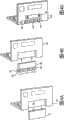
图4A-4C是笔记本电脑的底部的示意图,其示出结合采用根据本发明的另一个优选实施例所构造且可操作的混合电池系统的不同方法;图4A示出对现有技术的标准电池的结合采用,图4B和图4C示出结合采用本发明的混合电池的不同的优选方法;4A-4C are schematic views of the bottom of a notebook computer showing different ways of incorporating a hybrid battery system constructed and operative in accordance with another preferred embodiment of the present invention; The combined use of Figure 4B and Figure 4C shows a combination of different preferred methods of hybrid batteries of the present invention;
图5是根据本发明的进一步的优选实施例的说明充电控制算法的伏安控制特性的曲线图;5 is a graph illustrating the volt-ampere control characteristics of the charging control algorithm according to a further preferred embodiment of the present invention;
图6是与30Wh非混合可充电电池的循环寿命相比较、说明从使用根据本发明的30Wh容量的混合电池供电的笔记本电脑的可充电主电池所获得的增加的循环寿命的曲线图;6 is a graph illustrating the increased cycle life obtained from a rechargeable main battery for a notebook computer powered by a hybrid battery of 30 Wh capacity in accordance with the present invention, as compared to the cycle life of a 30 Wh non-hybrid rechargeable battery;
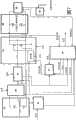
图7是本发明的双向电池充电控制器的电力控制系统的方框电路图,其示出使本文中所述的各种部件运行的优选结构;FIG. 7 is a block circuit diagram of the power control system of the bi-directional battery charge controller of the present invention showing the preferred structure for operating the various components described herein;
图8示意性说明本发明的进一步的优选实施例,从而在便携式设备外部安装和使用作为外部双向充电器单元的辅助电池;Figure 8 schematically illustrates a further preferred embodiment of the invention whereby an auxiliary battery is mounted and used externally to the portable device as an external bi-directional charger unit;
图9是与图1-3所示的方框电路示意图相似的方框电路示意图,其示出根据图8所示的优选实施例的本发明的双向电池系统的操作;并且FIG. 9 is a block circuit schematic similar to that shown in FIGS. 1-3 illustrating operation of the bi-directional battery system of the present invention in accordance with the preferred embodiment shown in FIG. 8; and
图10示出使用便携式外部充电器输入电流以给便携式电子设备的电池充电时的情况。FIG. 10 illustrates the situation when a portable external charger is used to input current to charge a battery of a portable electronic device.
具体实施方式Detailed ways
本发明的双向电池系统的目的在于提供用于例如移动电话、摄像机、笔记本电脑等的便携式电子设备的辅助电池,该辅助电池提供使用方便且通用的电力,以扩充设备内的可充电主电池,并且该辅助电池可包括不同类型的单体电池以用于备用电源功能。The purpose of the bi-directional battery system of the present invention is to provide an auxiliary battery for portable electronic devices such as mobile phones, video cameras, notebook computers, etc., which provides easy-to-use and versatile power to augment the rechargeable main battery within the device, And the auxiliary battery may include different types of single cells for backup power function.
现在参考图1,其说明根据本发明的优选实施例所构造且可操作的双向电池系统的整体布局。以常用方式通过其自身内置的可充电电池12给便携式设备的操作电路供电,该内置可充电电池12可优选为Li离子型电池。内部保护电路14保护内置可充电电池免受有害状况,包括过度充电、过度放电和过高温度。此外,提供辅助或附加电池20,其可被合并到设备内,当且如果有必要时容易更换电池。应该注意的是,因辅助“电池(battery)”可包括单个单体电池或包括几个单体电池,所以在本申请中关于辅助电池术语电池(battery)和单体电池(cell)有时可以互换使用,尽管它们形式上不同,从技术上来讲电池(battery)是一个以上单体电池的组件。然而,不论使用单体电池或是电池作为辅助“电池”,可知本发明是可应用的,并且当广泛使用术语电池时,可知其含义有时可互换,而事实上仅想表达单个单体电池。Reference is now made to FIG. 1 , which illustrates the overall layout of a bi-directional battery system constructed and operative in accordance with a preferred embodiment of the present invention. The operating circuits of the portable device are powered in the usual manner by its own built-in
辅助电池20优选包括用于将辅助电力输入给设备的电力系统的可替换、易得到的标准尺寸的单体电池(cell)或电池(cells)。然而,该辅助电池在两个主要方面与在背景技术部分中提及的现有技术中所描述的那些电池不同。The
(i)第一,该辅助电池可包括单体原电池或多个单体原电池、或单体可充电电池或可充电电池。(i) First, the auxiliary battery may comprise a single primary battery or a plurality of single primary batteries, or a single rechargeable battery or rechargeable batteries.
(ii)第二,该辅助电池20通过双向充电器22与设备连接,其中双向充电器22监控和控制电流从电池流入设备的电力系统以及从设备的电力系统流入电池。此外,双向充电器22作为电压转换器以将一般较低的电池电压转换到设备的电力系统所需的较高电压,相反地将例如当连接到外部壁式插座18上的存在于设备内的较高的充电电压转换到用于给辅助电池充电的较低的电压。如果该辅助电池具有比设备的主电池高的端电压,该转换器相应地操作。总之,为了控制来自外部壁式插座的充电速率,包括充电控制器16使其作为设备电路的一部分或将其包括在壁式插座18内。(ii) Second, the
该第二个方面(ii)提供具有双功能的双向充电器。除了使用来自辅助电池的能量给可充电主电池充电以外,该充电器还可通过设备的内部充电电路给辅助电池再充电。这意味着经双向充电器22转移的能量可朝两个方向流动-由此得到术语“双向充电器”。在图2和3的方框电路图中显示了这两个不同流动方向,其中电流方向由箭头表示,如下:This second aspect (ii) provides a bi-directional charger with dual functionality. In addition to charging the main rechargeable battery with energy from the auxiliary battery, the charger also recharges the auxiliary battery through the device's internal charging circuitry. This means that the energy transferred via the
(a)电流从辅助电池20流到设备的可充电主电池12,从而当需要时将可充电电池能量增强。在图2所示的方框电路图中示意性地示出了该情况。(a) Current flows from the
(b)电流经双向充电器22从连接到设备10从而连接到其可充电电池12的交流壁式插座充电器18、16流到辅助电池20。因为本发明的特征,辅助电池是可充电电池,所以这种选择是有用的。在图3所示的方框电路图中示出了该情况。(b) Current flows from the AC
该双向充电器必须能够提供并且相应地控制辅助电池的这两种可能操作的应用。为了有效满足这些功能,该双向充电器22优选是基于微处理器的。在优选包括例如镍金属氢化物(NiMH)电池或镍镉(NiCd)电池等二次电池和例如碱性电池或燃料电池的原电池或单元原电池的单单体电池或多单体电池辅助电池20,和优选包括Li离子电池的设备的单单体电池或多单体电池主电池之间提供电流接口。因主电池的额定操作电压一般高于辅助电池的额定操作电压,所以为了方便,称该辅助电池侧为“低电压侧”,称设备的可充电主电池侧为“高电压侧”。在从辅助电池20获得电流时,该双向充电器能将电流从低压侧传送到高压测,或者在外部壁式插座充电器18与高压侧连接时,该双向充电器能将电流从高压侧传送到低压侧,并且其能控制电池在上述方向上充电。The bi-directional charger must be able to provide and control the application of these two possible operations of the auxiliary battery accordingly. In order to efficiently fulfill these functions, the
根据需要哪个电流方向,双向充电器还允许对NiMH、NiCd和Li离子电池的化学属性的最优和自动的充电控制。在低压侧,该双向充电器自动检测辅助电池的化学属性,并且如果辅助电池包括单体原电池或多个单体原电池,其阻止充电。相反地,当从辅助电池向Li离子主电池充电时,该双向充电器实时调节充电电流以获得作为Li离子电池的电压的函数的最优能量转移。因原电池一般具有高的内电阻,当放电电流升高时,原电池的效率降低。因此,当在辅助电池内使用原电池时,当Li离子相对较满时,减小从辅助电池到Li离子电池的充电电流以提高效率,并且当Li离子相对较空时,增加从辅助电池到Li离子电池的充电电流以确保可立即操作设备。如此,如果Li离子电池几乎或完全耗尽,仅使用辅助电池立即使用设备是可能的。在正常情况下,因为在高放电率下高消耗设备的效率低,所以使用原电池不能良好地操作高消耗设备。特殊的充电电流算法能够在允许立即使用设备和随时间保持良好的效率之间实现平衡,即使利用耗尽或几乎耗尽的Li离子电池。此外,因辅助电池通过主电池给设备供电,这允许具有低内电阻的主电池传递例如移动电话等设备所需的任何短的、高的电流峰值。如果仅使用原电池或燃料电池给移动电话供电,因为原电池或燃料电池的内电阻相对较高将阻止它们处理有时由电话获得的高的电流峰值,所以一般移动电话的功能性将显著削弱。根据本发明,即使主电池确实完全耗尽,当辅助电池提供低电平连续电流用于操作设备时,因主电池还可提供传送所需高电流,所以设备仍然是起作用的,因为这些电流是超短时峰值电流从而从主电池获取极小的累积能量。此外,当从NiMH或NiCd辅助电池对Li离子主电池充电时,由Li离子供电的设备将两个化学电池整个看作单个电池源。本发明的系统还优选合并辅助电池内的和主电池内的两个电池温度传感器,并且根据所测量的电池温度,双向充电器朝当前工作的任何方向调节充电电流。Bi-directional chargers also allow optimal and automatic charge control for NiMH, NiCd and Li-ion battery chemistries, depending on which current direction is required. On the low voltage side, the bi-directional charger automatically detects the chemistry of the auxiliary battery and prevents charging if the auxiliary battery consists of a single primary battery or multiple single primary batteries. Conversely, when charging from the auxiliary battery to the main Li-ion battery, the bi-directional charger adjusts the charging current in real time to obtain optimal energy transfer as a function of the voltage of the Li-ion battery. Since primary cells generally have high internal resistance, the efficiency of primary cells decreases as the discharge current increases. Therefore, when using the primary battery inside the auxiliary battery, when the Li ions are relatively full, reduce the charging current from the auxiliary battery to the Li-ion battery to improve efficiency, and when the Li ions are relatively empty, increase the charging current from the auxiliary battery to the Li-ion battery. Li-ion battery charging current to ensure immediate operation of the device. Thus, if the Li-ion battery is almost or completely depleted, it is possible to use the device immediately using only the auxiliary battery. Under normal conditions, high drain devices do not operate well with primary batteries because of their inefficiency at high discharge rates. A special charge current algorithm strikes a balance between allowing immediate use of the device and maintaining good efficiency over time, even with a depleted or nearly depleted Li-ion battery. Furthermore, since the auxiliary battery powers the device through the main battery, this allows the main battery with low internal resistance to deliver any short, high current peaks required by a device such as a mobile phone. If only primary batteries or fuel cells were used to power a mobile phone, the functionality of a typical mobile phone would be significantly impaired because the relatively high internal resistance of the primary or fuel cells would prevent them from handling the high current peaks sometimes drawn by the phone. According to the present invention, even if the main battery does become completely drained, while the auxiliary battery supplies a low level of continuous current for operating the device, the device is still functional because the main battery can also provide the high current required to deliver the current, because these currents It is an ultra-short-duration peak current to draw very little accumulated energy from the main battery. Furthermore, when charging a Li-ion main battery from a NiMH or NiCd auxiliary battery, a Li-ion powered device sees both chemistries as a whole as a single battery source. The system of the present invention also preferably incorporates both battery temperature sensors in the auxiliary battery and in the main battery, and based on the measured battery temperature, the bi-directional charger adjusts the charge current in whatever direction it is currently operating.
因该双向充电器是基于微处理器的,所以其执行是灵活的,并且该双向充电器优选包括根据特定应用的特殊需要可编程的若干I/O接口线。Since the bi-directional charger is microprocessor based, its implementation is flexible and preferably includes several I/O interface lines that are programmable according to the specific needs of a particular application.
优选通过配置在该双向充电器的读出电路和电压转换电路的方式提供双向充电器的某些上述操作特征。Some of the above-mentioned operational features of a bi-directional charger are preferably provided by means of sense circuitry and voltage conversion circuitry configured in the bi-directional charger.
如先前所提的辅助电池可包括例如NiMH或NiCd电池的单体可充电电池或多个单体电池,或者例如碱性电池或燃料电池的单体原电池或多个单体原电池。对于每种情况,系统不同地运行。The auxiliary battery as previously mentioned may comprise a single rechargeable battery or cells such as a NiMH or NiCd battery, or a single primary cell or cells such as an alkaline battery or a fuel cell. For each case, the system operates differently.
如果辅助电池是可充电的,可认为辅助电池和设备的可充电主电池相当于一个大的可充电主电池,因此辅助电池给可充电主电池有效地增加了容量。因此,因为辅助电池是设备自身的可充电电池的有效附加,可认为有效地使用了用于辅助电池的空间。在该情况下,根据本发明的另一个优选实施例,因辅助电池是易卸的,并且其有效地提供了设备的可充电电池的总容量的一部分,所以可充电主电池可永久地接入设备,使得其不再是可拆卸的,因为无需具有两组可替换的可充电电池。使用这样的永久内置式主电池有许多优点,如下:If the auxiliary battery is rechargeable, the auxiliary battery and the main rechargeable battery of the device can be considered to be equivalent to one large rechargeable main battery, so that the auxiliary battery effectively adds capacity to the main rechargeable battery. Therefore, because the auxiliary battery is an efficient addition to the device's own rechargeable battery, the space for the auxiliary battery can be considered to be used efficiently. In this case, according to another preferred embodiment of the present invention, the main rechargeable battery is permanently plugged in because the auxiliary battery is easily removable and effectively provides a fraction of the total capacity of the rechargeable battery of the device. device so that it is no longer detachable since there is no need to have two sets of replaceable rechargeable batteries. There are many advantages to using such a permanently internal main battery, as follows:
(i)可充电主电池的性能提高,因为不仅由于电池被硬接入设备内而具有减小的接触电阻,而且还具有增加电池容量的可能性,因为通过将电池永久合并入设备内、消除对用于电池的可拆卸组件和触头的需要而节省了空间。(i) Improved performance of the rechargeable main battery due to not only reduced contact resistance due to the battery being hard-wired into the device, but also the potential for increased battery capacity due to the permanent incorporation of the battery into the device, eliminating Space is saved by the need for removable components and contacts for the battery.
(ii)具有较高的可靠性和安全性,因为可充电主电池是内置的,因而用户安装非原装电池作为主电源不再可能。(ii) It has high reliability and safety, because the rechargeable main battery is built-in, so it is no longer possible for the user to install a non-original battery as the main power supply.
(iii)具有较低的制造成本,因为(a)不需要内部电池组设计、内部电池组材料和制造成本以及金电池组触头,(b)因为在与整个设备相同的工艺而不是在分离的工艺中装配可充电主电池,所以装配更简单,以及(c)产品的集成更容易,消除了在使内电池组适应于设备内的可利用空间方面的特殊考虑的需要。(iii) have lower manufacturing costs because (a) no internal battery pack design, internal battery pack materials and manufacturing costs, and gold battery pack contacts are required, (b) because they are produced in the same process as the entire device rather than in separate Assembling the rechargeable main battery in a unique process, so assembly is simpler, and (c) product integration is easier, eliminating the need for special considerations in adapting the inner battery pack to the available space within the device.
当辅助电池是原电池时,使用永久内置式主电池的上述优点也是可适用的,尽管这样的实施例一般在商业上用途较少。The above advantages of using a permanently internal primary battery are also applicable when the secondary battery is a primary battery, although such embodiments are generally less commercially useful.
因为例如利用任何其它非插拔式部件通过焊开或重新将电池焊入电路的方式,可充电主电池将仍然是可替换的,所以应当理解术语永久内置式主电池不应该按其字面意思理解。It should be understood that the term permanent internal main battery should not be taken literally, since the rechargeable main battery will still be replaceable, for example by soldering off or re-soldering the battery into the circuit, with any other non-pluggable part .
如果辅助电池是原电池或单体原电池,其可作为设备的可充电主电池的辅助能量增强,能够给完全不依赖于任何电出口或其它这样的源的主电池提供再充满的电荷,并且能够利用这样的原电池的广泛的可用性和低价格。If the auxiliary battery is a primary battery or single primary battery, it acts as an auxiliary power boost to the rechargeable main battery of the device, capable of providing a rechargeable charge to the main battery completely independent of any electrical outlet or other such source, and The wide availability and low price of such primary cells can be exploited.
使用本发明的辅助电池具有许多操作优点:There are a number of operational advantages to using the auxiliary battery of the present invention:
(i)这样的辅助电池为衰退的主电池提供可选的备用能量或能量增强。(i) Such auxiliary batteries provide optional backup power or energy boost for a failing main battery.
(ii)如果该辅助电池是可充电的,那么可认为两个电池都作用为一个大的可充电电池,从而提供了有效替换某些“大”电池的单体电池的选择,即替换辅助电池的单体电池。这种替换将使得“大”电池能够具有较长寿命,由于两个原因:(ii) If the auxiliary battery is rechargeable, then both batteries can be considered to function as one large rechargeable battery, thereby providing the option of effectively replacing the single cells of some "large" batteries, i.e. replacing the auxiliary battery single battery. This replacement will allow the "big" battery to have a longer life, for two reasons:
(a)当“大”电池的一部分是可替换的时,该替换提供具有新容量的部分电池的补充;以及(a) when a portion of a "big" battery is replaceable, the replacement provides for the replacement of a portion of the battery with new capacity; and
(b)可设计设备的电力管理以仅在辅助电池耗尽或几乎耗尽之后使用可充电主电池,从而因为对可充电主电池的总的使用较少,所以可延长可充电主电池自身的寿命。(b) The power management of the device can be designed to use the main rechargeable battery only after the auxiliary battery is depleted or nearly depleted, thereby prolonging the life of the main rechargeable battery itself because the overall use of the main rechargeable battery is less. life.
(iii)从市场的角度来看,因为可充电主电池是内在的并且一般不可接触,并且消费者仅接触并看见标准尺寸的辅助电池,所以用户认为该电池比没有这样的辅助电池的类似设备的电池小。(iii) From a marketing perspective, because the rechargeable main battery is internal and generally inaccessible, and consumers only touch and see a standard-sized auxiliary battery, users perceive the battery as better than a similar device without such an auxiliary battery The battery is small.
为了实现该辅助电池的准确操作,根据本发明的各种优选实施例,双向充电器应当具有许多操作特征,如下:In order to achieve accurate operation of the auxiliary battery, according to various preferred embodiments of the present invention, the bi-directional charger should have a number of operational features, as follows:
(i)需要实时充电电流控制以控制从辅助电池到可充电主电池的电流,以确保典型的便携式设备的最佳结果,特别是具有辅助原电池的便携式设备。使用下文中描述的电流控制算法执行该控制。(i) Real-time charge current control is required to control the current flow from the auxiliary battery to the rechargeable main battery to ensure optimal results for typical portable devices, especially those with auxiliary primary batteries. This control is performed using the current control algorithm described below.
(ii)双向充电器应当具有相关的控制算法,用于自动检测辅助电池的化学属性,即其是否为原电池或可充电电池。(ii) Bi-directional chargers should have relevant control algorithms for automatically detecting the chemical properties of the auxiliary battery, ie whether it is a primary battery or a rechargeable battery.
(iii)如果检测到可充电电池的化学属性,那么双向充电器应当确保控制从交流插座充电器(当使用时)到辅助电池的充电电流。(iii) If the chemistry of the rechargeable battery is detected, the bi-directional charger should ensure control of the charging current from the AC outlet charger (when used) to the auxiliary battery.
(iv)通过设备的主用户接口,优选通过在屏幕上的菜单,可优选使辅助电池的激活或去激活为任选的或用户可选的。可替换地且优选地,可以使用设备/电池上的机械开关。(iv) Activation or deactivation of the auxiliary battery may preferably be made optional or user selectable via the main user interface of the device, preferably via an on-screen menu. Alternatively and preferably, a mechanical switch on the device/battery can be used.
(v)在设备的主显示屏幕上示出选项,即辅助电池的状态,例如该辅助电池是否闲置,或对可充电主电池或设备提供电流,或其自身被充电。(v) Show options on the main display screen of the device, ie the status of the secondary battery, eg whether it is idle, or provides current to the rechargeable primary battery or the device, or is itself charged.
现在参考图4A-4C,其是膝上电脑30的底部的示意图,其示出根据本发明的更优选的实施例的合并辅助电池和双向充电控制系统的方法。在图4A内示出插入计算机30的背侧的凹部34内的现有技术的标准可充电电池组32的典型例子。在图4B内示出根据本发明的优选实施例的扩充式混合电池组36,其尺寸与一些膝上型电脑制造商所供应的扩充式电池组的尺寸相似,其中辅助电池38被安装在电池组背面的分离室40内。该分离室具有用于辅助电池的常规的电池接点,并且优选具有滑动或铰链或可拆卸盖子42或其它构件,因此,如果需要,用户容易使用该分离室,以替换辅助电池38。辅助电池可优选为一组4或6个、易得到的、AA尺寸的单体原电池或单体可充电电池。双向充电控制器电路优选配置在计算机的电力管理电路或电池组自身内。Reference is now made to FIGS. 4A-4C , which are schematic illustrations of the bottom of a
根据一个示范组装设计,这样的混合电池组实施例可包括:According to one exemplary package design, such a hybrid battery embodiment may include:
(i)具有28瓦特小时(Wh)的可充电能量的标准Li离子电池组;以及(i) a standard Li-ion battery pack with a rechargeable energy of 28 watt hours (Wh); and
(ii)如果使用NiMH电池提供10Wh的附加可充电能量,或者如果使用Li/FeS2单体原电池提供高达14Wh的一次能量的辅助电池。该辅助电池可优选以在位于电池组的背面的17mm深、17mm高的额外的壳体内的室内的一组4个AA尺寸的单体电池的形式存在。(ii) If using a NiMH battery to provide 10Wh of additional rechargeable energy, or if using a Li/FeS2 single primary battery to provide an auxiliary battery with up to 14Wh of primary energy. The auxiliary battery may preferably be in the form of a set of 4 AA size cells in a chamber located within a 17mm deep by 17mm high additional housing at the back of the battery pack.
在这样的实施例中,在计算机背面的室将容易用于移除其盖子以在必要时替换辅助电池。In such an embodiment, a compartment on the back of the computer would be readily available to remove its cover to replace the auxiliary battery if necessary.
现在参考图4C,其是笔记本电脑50的示意图,其中没有将混合电池设计成如图4B内所示的标准电池组的插入式替换,而是将其设计成计算机的组成部分。在这样的实施例中,Li离子主电池优选被配置在计算机内作为不可拆卸式组件52,不论是硬线接的或是插入式的,但不像目前的实际应用那样,优选使用户不易接触。另一方面,将辅助电池54的电池设置成用户可拆卸的,例如通过将它们安装在为此目的所设计在计算机内的空腔56内,优选具有可拆卸、可伸缩或铰链接合的盖子58。如果主电池52是硬线接在内部的,这类设计提供改进的电源性能,但是,不像图4B的实施例那样,这确实需要将混合电池的设计并入整个笔记本电脑的机械设计工艺中。Reference is now made to FIG. 4C, which is a schematic illustration of a
根据本发明的进一步的优选实施例,双向充电控制系统配有用于确保在主电池的各种耗尽状态下最佳利用辅助电池和主电池的电力管理算法。根据本发明的各种实施例提供几个优选的电力管理算法。尽管这些算法可用于任何移动设备,它们特别适用于便携式计算机和移动电话的应用,并且照此将在下面对这些算法进行描述。According to a further preferred embodiment of the present invention, the bi-directional charge control system is equipped with a power management algorithm for ensuring optimal utilization of the auxiliary and main batteries in various depletion states of the main battery. Several preferred power management algorithms are provided according to various embodiments of the present invention. Although these algorithms can be used with any mobile device, they are particularly suitable for use in portable computers and mobile phones, and as such will be described below.
根据电力管理算法的一个优选实施例,第一算法确保当辅助电池在使用中时,根据设备的即时电流需要实时调节所提取的电流,从而避免低效的高电流从辅助电池排出。因此,在常规操作条件下,当主电池未完全耗尽时,或者当设备未开启且主电池由辅助电池充电时,根据主电池和辅助电池的类型,该算法确保遵循智能充电模式(profile)以保证最有效使用辅助电池的有效电力容量。According to a preferred embodiment of the power management algorithm, the first algorithm ensures that when the auxiliary battery is in use, the current drawn is adjusted in real time according to the immediate current needs of the device, thereby avoiding inefficient high current draining from the auxiliary battery. Therefore, under normal operating conditions, when the main battery is not completely drained, or when the device is not switched on and the main battery is charged by the auxiliary battery, depending on the type of the main battery and the auxiliary battery, the algorithm ensures that the intelligent charging profile (profile) is followed to Guarantees the most efficient use of the available power capacity of the auxiliary battery.
因为发射状态和接收状态下设备所提取(drawn)的电流的变化大,所以该充电控制算法对于移动电话的使用特别重要。在发射过程中,峰值电流要求可能远远超过辅助电池单独可提供的电流,特别是当辅助电池包含原电池时。因此,例如,虽然给移动电话供电所需的最大平均电流一般为400mA的数量级,但是在传送过程中还使用高达2A的电流峰值。移动电话通常还在3-4.1V下运行。这意味着为了给设备供应峰值电流,用于该应用的混合电池的原电池必须提供至少6W的功率。因为标准碱性原电池在大约1.2V运行,这将需要来自电池的5A的电流峰值。因为原电池的高内电阻,所以原电池一般不能提供这样的电流负载。This charging control algorithm is particularly important for mobile phone use because of the large variation in the current drawn by the device in the transmitting and receiving states. During launch, peak current requirements can far exceed what the auxiliary battery alone can provide, especially when the auxiliary battery contains the primary battery. Thus, for example, while the maximum average current required to power a mobile phone is typically on the order of 400mA, current peaks of up to 2A are also used during transmission. Mobile phones also typically operate at 3-4.1V. This means that in order to supply the peak current to the device, the primary cells of the hybrid battery used for this application must provide at least 6W of power. Since standard alkaline primary cells run at about 1.2V, this would require a current peak of 5A from the battery. Primary cells generally cannot provide such current loads because of their high internal resistance.
使用本发明的混合电池,通过程序化充电控制器使得可充电主电池象充电电容器一样供应峰值电流,而辅助原电池象电源一样满足平均电流要求而解决该问题。因为峰值只持续非常短的时间,在例如上述移动电话的情况下满足峰值电流要求事实上只需要来自二次电池的极小的能量。因此,充电控制器必须响应平均电流负载,而不是瞬时电流。Using the hybrid battery of the present invention, this problem is solved by programming the charge controller so that the rechargeable primary battery acts like a charging capacitor to supply the peak current, while the auxiliary primary battery acts like a power supply to meet the average current requirements. Since the peak lasts only for a very short time, meeting the peak current requirement in the case of eg the mobile phone mentioned above requires practically very little energy from the secondary battery. Therefore, the charge controller must respond to the average current load, not the instantaneous current.
现在参考图5,其是根据本发明的进一步的优选实施例说明充电控制器的算法的电流-电压控制特性的曲线图。该特性必定从完整混合电池供应足够的电流以操作设备,另一方面,其必须最小化与从辅助原电池提取过高电流相关的损耗。图5说明怎样控制来自辅助原电池的作为主二次电池电压的电压函数的充电电流。因为低主电池电压是部分耗尽的主电池的迹象或设备的高平均电流使用的迹象,所以当主二次电池电压低时,保持充电电流在高电平。然后,如主电池的电压上升所表明的那样,当进一步充电主电池时,降低充电电流直至将充电电流稳定在恒定的最小值。从而,在任何情况下,保持充电电流在其最小可能值,将来自原电池的内电阻的损耗最小化。Reference is now made to FIG. 5, which is a graph illustrating the current-voltage control characteristics of an algorithm of a charge controller according to a further preferred embodiment of the present invention. This characteristic must supply enough current from the full hybrid battery to operate the device, on the other hand it must minimize the losses associated with drawing too high current from the auxiliary primary battery. Figure 5 illustrates how the charging current from the auxiliary primary battery is controlled as a function of the voltage of the main secondary battery voltage. Since low primary battery voltage is a sign of a partially depleted primary battery or high average current usage of the device, the charge current is kept at a high level when the primary secondary battery voltage is low. Then, when further charging the main battery, as indicated by the voltage rise of the main battery, the charging current is reduced until the charging current is stabilized at a constant minimum value. Thus, in any case, keeping the charging current at its smallest possible value minimizes the losses from the internal resistance of the primary cell.
再一次参考图5,负载电流线被描绘为高负载和低负载。当设备具有高平均电流负载时,在启动时程序化该控制器以超过所需的平均电流从而确保足够电流可用于操作设备并且添满主电池的任何损耗。然后,该特性使所供应电流减小到充电电流与负载电流相等的平衡水平。在初始超越期,由于过剩电流而供应的能量未损耗,但是其被存储在二次电池内。当原电池接近于耗尽,并且可能不再提供最小操作电流时,依靠该电流。如果控制特性是如此以致于达不到对所需平均电流的超越,该设备将不能立即响应操作。Referring again to FIG. 5, the load current lines are depicted as high load and low load. When the device has a high average current load, the controller is programmed at startup to exceed the average current required to ensure that enough current is available to operate the device and top up any drain on the main battery. This feature then reduces the supplied current to a balanced level where the charge current equals the load current. During the initial override period, the energy supplied due to the excess current is not lost, but it is stored in the secondary battery. This current is relied upon when the primary cell is close to being depleted and may no longer provide the minimum operating current. If the control characteristics are such that an override of the required average current cannot be achieved, the device will not respond immediately to operation.
如图5所示,当设备关闭或者处于具有极低电流负载的备用模式时,该控制器同样以高充电电流启动,然后迅速将电流减小到最小电流。因为负载电流非常低,原电池可保持以低电流稳定地、缓慢地给二次电池充电,这是从原电池提取电流的最有效的方法。As shown in Figure 5, when the device is off or in standby mode with a very low current load, the controller also starts up with a high charge current and then quickly reduces the current to the minimum current. Because the load current is very low, the primary battery can keep charging the secondary battery steadily and slowly at a low current, which is the most efficient way to draw current from the primary battery.
因此,图5的曲线说明充电控制算法怎样覆盖包括当二次电池接近满容量时的电压控制充电的使用情况的整个范围,这是Li离子电池的要求。Thus, the graph of Figure 5 illustrates how the charge control algorithm covers the entire range of use cases including voltage controlled charging when the secondary battery is close to full capacity, which is a requirement for Li-ion batteries.
在例如膝上型电脑等具有相对较高的电力负载的设备中,另外设计电力管理算法以使辅助电池能够在主电池几乎耗尽的最坏的情况下不中断地给设备供电。总之,使用原电池的辅助电池具有限定的电力输出,而该输出可能不足以单独给设备供电。因此,如果在切换到辅助电池之前,允许主电池完全耗尽,则在能够继续工作之前,用户将不得不稍许等待辅助电池给主电池充电。因此,该算法通过在主电池接近耗尽时首先检测而运行。通过预定标准确定接近耗尽的程度,但是一般为总充电容量的10%或以上,并且优选由主电池的端电压所确定。当检测到这样的状态时,电力管理系统通过起动从辅助电池获取电力而采取适当的动作以便防止主电池完全耗尽,如果这还没有发生。可通过给用户指示执行该动作,优选接入辅助电池的屏幕显示信息或者可听报警信息,或者通过控制系统自动执行该动作。因此,辅助电池的电力与来自几乎耗尽的主电池的可利用的剩余电力一起使用,以提供足够的电力从而继续设备的立即操作,直至两个电池完全耗尽。当两个电池完全耗尽时,为了继续计算机的操作,安装新的辅助电池组以继续工作或给主电池充电,或者必须使对外部电源充电器的接入是可实现的。In devices with relatively high electrical loads, such as laptops, power management algorithms are additionally designed to enable the secondary battery to power the device without interruption in the worst case scenario where the main battery is nearly depleted. In summary, secondary batteries using primary cells have a limited power output that may not be sufficient to power the device alone. Therefore, if the main battery is allowed to drain completely before switching to the auxiliary battery, the user will have to wait a little while for the auxiliary battery to recharge the main battery before being able to continue working. Therefore, the algorithm operates by first detecting when the main battery is near depletion. The degree of near depletion is determined by predetermined criteria, but is generally 10% or more of the total charge capacity, and is preferably determined by the terminal voltage of the main battery. When such a condition is detected, the power management system takes appropriate action in order to prevent the main battery from being completely drained, if this has not already happened, by initiating power extraction from the auxiliary battery. This action can be performed by an instruction to the user, preferably an on-screen display message or an audible warning message that engages the auxiliary battery, or automatically by the control system. Thus, the auxiliary battery's power is used with the remaining power available from the nearly depleted main battery to provide sufficient power to continue immediate operation of the device until both batteries are completely drained. To continue operation of the computer when both batteries are completely depleted, a new auxiliary battery pack is installed to continue working or to charge the main battery, or access to an external power charger must be made available.
根据一个典型的实施例,需要14W功率来运行的笔记本电脑具有28Wh的Li离子主电池和由4个Li/FeS2的AA尺寸的单体电池组成的辅助电池,每个单体电池都能提供2A的最大输出电流。这意味着约2.5W的最大输出功率,即对于所有4个单体电池为10W。因为这些电池可提供约10Wh的能量,以该功率输出,电池可供给约1个小时的使用时间。因为笔记本电脑的功率损耗超过辅助电池的功率输出不大,假如当该电力管理算法命令接入辅助电池功率时,在主电池内剩余足够的功率,那么计算机可继续在合并的混合电池的充电寿命的剩余部分运行在其上上。在该例中,该算法应当确保在使用辅助电池之前Li离子电池内剩余至少4Wh(持续1小时输出4W的功率)。理论上,从这一时刻起,用户应该仍具有满60分钟的使用时间,从辅助电池获得10W,从Li离子电池获得4W。对于该剩余时间,通过使用辅助电池而有效提供的附加时间为43分钟。According to a typical embodiment, a notebook computer requiring 14W of power to run has a 28Wh Li-ion main battery and an auxiliary battery consisting of four Li/FeS2 AA-sized cells, each capable of providing 2A maximum output current. This means a maximum output power of about 2.5W, ie 10W for all 4 cells. Because these batteries can provide about 10Wh of energy, with this power output, the battery can provide about 1 hour of use. Because the power loss of the notebook computer does not exceed the power output of the secondary battery by much, the computer can continue for the charge life of the combined hybrid battery provided there is sufficient power remaining in the primary battery when the power management algorithm commands access to secondary battery power The rest of the run on it. In this example, the algorithm should ensure that there is at least 4Wh left in the Li-Ion battery (4W output for 1 hour) before using the auxiliary battery. In theory, from this point on, users should still have the full 60 minutes of use, with 10W from the secondary battery and 4W from the Li-ion battery. For this remaining time, the additional time effectively provided by use of the auxiliary battery is 43 minutes.
总之,应当注意的是,因为Li/FeS2电池具有比NiMH电池更高的能量密度,所以包含例如上述Li/FeS2电池的原电池的辅助电池与使用例如NiMH电池的二次电池的辅助电池相比为计算机提供更长的操作。然而,NiMH电池具有较高的电流容量,因此其能在主电池完全耗尽时单独给计算机供电。In summary, it should be noted that since Li/FeS2 batteries have a higher energy density than NiMH batteries, an auxiliary battery comprising a primary battery such as the above-mentioned Li/FeS2 battery is different from an auxiliary battery using a secondary battery such as a NiMH battery Compared to giving the computer a longer operation. However, NiMH batteries have a higher current capacity, so they can power the computer alone when the main battery is completely drained.
因为如果在其最大功耗时使用这种Li/FeS2电池,其不仅产生大量热量,而且以小于其最优效率操作,所以应当优选避免在上述最坏的情况下使用该Li/FeS2电池。根据本发明的另一个优选方法,程序化的电力管理系统以给用户提供可听见的或屏幕上的提前通知,即在主电池运行低时,建议用户开始使用辅助电池,即使主电池还没达到上述“接近耗尽”的阈值。该对于辅助电池的及时使用确保存储在其内的电力的最优效率。Because such a Li/FeS2 battery not only generates a lot of heat if used at its maximum power consumption, but also operates at less than its optimal efficiency, it should preferably be avoided to use this Li/FeS2 battery in the above worst case . In accordance with another preferred method of the present invention, the power management system is programmed to provide the user with an audible or on-screen advance notice advising the user to start using the auxiliary battery when the primary battery is running low, even if the primary battery has not yet reached The above "near depletion" threshold. This timely use of the auxiliary battery ensures optimal efficiency of the power stored therein.
所有可充电电池都具有有限的循环寿命-执行充电-放电循环的次数越高,其可用容量越低。当辅助电池包含例如NiMH电池等的二次电池时,主电池和辅助电池像一个大的可充电电池一样一起工作。如上文所提及,因为便宜的可充电辅助电池承担部分负载,这本身延长了昂贵的主电池的寿命。然而,除了该总的效果以外,根据本发明的进一步优选的算法,当辅助电池包含二次电池时,将设备程序化以管理主要来自于辅助电池的功耗,使得便宜的可替换的辅助电池经受许多充电/放电循环,否则这些充电/放电循环将由替换昂贵的主电池所提供。只要放电循环浅,即仅部分地在两次充电之间使电池放电,例如,一般是使用膝上型电脑的情况,则该算法确保几乎所有的电流损耗都来自辅助电池。使用该方法,实质上减少了替换昂贵的主电池的使用,因此充分增加了其寿命。All rechargeable batteries have a finite cycle life - the more times you perform charge-discharge cycles, the lower their usable capacity. When the auxiliary battery includes a secondary battery such as a NiMH battery, the main and auxiliary batteries work together like one large rechargeable battery. As mentioned above, this in itself extends the life of the expensive main battery because the cheap rechargeable auxiliary battery takes part of the load. However, in addition to this overall effect, according to a further preferred algorithm of the present invention, when the auxiliary battery comprises a secondary battery, the device is programmed to manage power consumption primarily from the auxiliary battery so that an inexpensive replaceable auxiliary battery Go through many charge/discharge cycles that would otherwise be provided by replacing the expensive main battery. As long as the discharge cycle is shallow, ie only partially discharges the battery between charges, as is typically the case with laptops, for example, the algorithm ensures that almost all the current draw comes from the auxiliary battery. Using this method, the use of replacing the expensive main battery is substantially reduced, thus substantially increasing its life.
为了说明该效果,现在参考图6,图6说明根据本发明使用30Wh容量的混合电池给笔记本电脑供电而获得的一些实验结果,该30Wh容量的混合电池包含提供10Wh能量的具有4个单体NiMH电池的辅助电池,以及提供20Wh能量的Li离子主电池。对于50%深度的放电循环,仅包含Li离子电池的30Wh容量的同等的电池在200循环之后将下降到75%的电荷保持量。另一方面,当使用本发明的混合电池时,如上侧曲线所示,在200循环之后,混合电池的Li离子部分仍然具有95%的保持量,并且在其保持量下降到75%之前,Li离子部分将仍容许数百个循环。因此,可以看出Li离子电池的寿命增加了好几倍。对于33%深度的放电,本发明的混合电池内的Li离子电池的寿命可能大约达到比仅具有Li离子电池的一般主电池更高的数量级。To illustrate this effect, reference is now made to FIG. 6, which illustrates some experimental results obtained in accordance with the present invention for powering a notebook computer using a hybrid battery of 30Wh capacity comprising a 4-cell NiMH battery providing 10Wh of energy. An auxiliary battery for the battery, and a Li-ion main battery that provides 20Wh of energy. For a 50% depth of discharge cycle, an equivalent battery of 30 Wh capacity comprising only a Li-ion battery would drop to 75% charge retention after 200 cycles. On the other hand, when using the hybrid battery of the present invention, as shown in the upper curve, after 200 cycles, the Li ion part of the hybrid battery still has 95% retention, and before its retention drops to 75%, the Li ion The ionic part will still tolerate hundreds of cycles. Therefore, it can be seen that the lifetime of the Li-ion battery is increased several times. For a 33% depth of discharge, the lifetime of the Li-ion battery within the hybrid battery of the present invention may be approximately an order of magnitude higher than a typical primary battery with only the Li-ion battery.
现在参考图7,该图是示出使本发明的上述特征能够实现的结构的双向电池充电控制器的电力控制系统的方框电路图。图7所示的实施例是较普通的情况,其中给设备供电的主电池的电压比辅助电池的高。然而,在一些设备中还可发现相反情况,其中给设备供电的主电池的电压比辅助电池的低,并且在这样的情况下,需要图7的实施例的方框电路的一些电路功能是相反的,但是总体功能结构是相似的。Referring now to FIG. 7, this figure is a block circuit diagram showing a power control system of a bi-directional battery charge controller of a configuration enabling the above-described features of the present invention. The embodiment shown in Figure 7 is the more general case where the primary battery powering the device is at a higher voltage than the secondary battery. However, the reverse may also be found in some devices where the primary battery powering the device is at a lower voltage than the secondary battery, and in such cases some circuit functions requiring the block circuits of the embodiment of FIG. 7 are reversed. , but the overall functional structure is similar.
现在参考图7,优选构造辅助电池81,使得可分别确定每个单体电池的电压。这可通过给每个单独的单体电池提供从电池的两个端到外部的触头而实现。这能够使电池化学属性的检测算法实现,例如在待对辅助电池的每个单体电池进行分案申请的本发明的共同未决的申请“用于电池供电设备充电方法”中所描述的算法。然后,该控制系统可给用户提供关于电池的任何特定的单体电池的警报。电压接头通过开关部件82与其余的控制电路连接。在图7所示的例子中,示出具有两个单体电池的辅助电池,因此需要三条导线输出到开关部件以允许确定两个单体电池中的每一个的电压。组织开关部件82以给其余电路一次输出在辅助电池一端和仅一个单体电池的一端之间的电压。该特征用于单体电池平衡算法,其也在本发明人的共同未决申请“用于电池供电的设备的充电方法”中得以描述。Referring now to FIG. 7, the
到达或来自辅助电池81的电流流入双向DC-DC功率级84,该功率级84是双向电压转换装置,其允许电流从辅助电池81流到主电池85,反之亦然,从而根据电流的方向转换端电压。Current to or from the
通过双向电流传感器83测量流入或流出辅助电池81的电流的幅值,所述双向电流传感器83感应流过双向DC-DC转换器84内的电感器的电流。因为电流传感器的一些设计需要知道电流的方向,所以根据从控制块88所接收的信号反转感应到电流的方向。The magnitude of the current flowing into or out of the
包括一个或多个单体电池的用于给设备89供电的主电池85通常包括可充电Li离子电池。通常,主电池85是物理地置于便携式设备内的。按照惯例,在该便携式设备内配置壁插式充电器90,用于在需要充电时从例如干线电源等的外部电压源充电。该便携式设备还可从辅助电池81接收能量。A
控制块88是双向电池充电控制器的主要控制单元,并且其控制整个电路的总体操作。该控制块88接收与每个单体电池的电压、电流和温度相关的输入,并且使用上述算法控制整个系统,包括控制电流的期望电平和电流方向。通过控制块88确定电流的期望电平。从控制台88输出的控制电平或电流的方向可用于关闭电流。可通过使用在这种设备内采用的标准数据通信线而实现便携式设备89和控制块88之间的数据通信,并且该数据通信线用于从设备传输用户生成的命令,并将控制产生的信号返回用户。The
许多附加的控制元件用于图7的结构内。电压和温度的检测块86与辅助电池81连接,并且优选分别检测辅助电池81内的每个单体电池的端电压和温度。通过使用电流模式控制循环将适当占空比的PWM脉冲传送给双向DC-DC功率级84内的驱动器,电流控制器87控制通过DC-DC转换器的电流电平。根据从控制块88接收的期望电流电平设定值输出PWM脉冲。A number of additional control elements are used within the structure of FIG. 7 . The voltage and
电流控制器87还接收来自控制块88的系统时钟和来自电流传感器83的有效电流电平的输入。The
现在参考图8,图8说明本发明的进一步的优选实施例,其中在包含主电池的便携式设备104外部安装并使用辅助电池100于。如图所示,辅助电池100被装入单独的壳体102内,优选通过单个连接器28和挠性导线106将其与便携式设备连接,从而插入便携式设备的外部充电输入口108内。在该实施例中,还将双向充电控制器配置在优选为印刷电路板110上的包含辅助电池的壳体内。因此,在例如在没有干线充电电源接入、设备的主电池耗尽的情形下,可认为该辅助电池相当于设备的小型便携式外部充电器或电源。Reference is now made to FIG. 8, which illustrates a further preferred embodiment of the present invention in which an
该便携式外部充电器的双向充电控制器优选并入上述图7中所示的控制器电路的所有功能。然而,两个功能是非常重要的。首先,因为壳体的暴露性质,该单元检测插入壳体内的电池的电池化学属性以防止对原电池充电是重要的。此外,该单元有效地转换根据辅助电池是供应电流还是被充电而控制的电流的电压是重要的。在先前所述的实施例中,辅助电池被配置在假定主电池的特性和要求已知的公知设备内,而该实施例与先前所述的那些实施例不同,其涉及可用于给具有兼容连接器的任何设备供电的便携式电源。因此,因为制造商不能控制单元的辅助电池将要供电的设备的类型,所以可能需要将附加功能并入控制电路,例如检查设备的主电池的状态以确定其适于充电,或者例如通过LED等向用户提供该单元包括准备供应电流的电池的视觉信号,等等。The bi-directional charge controller of the portable external charger preferably incorporates all the functions of the controller circuit shown in FIG. 7 described above. However, two functions are very important. First, because of the exposed nature of the housing, it is important that the unit detects the battery chemistry of a battery inserted into the housing to prevent recharging of the primary battery. Furthermore, it is important that the unit efficiently converts the voltage of the current controlled according to whether the auxiliary battery is supplying the current or being charged. Unlike the previously described embodiments in which the auxiliary battery is configured within a known device assuming that the characteristics and requirements of the main battery are known, this embodiment relates to the Portable power supply for any device powered by a Therefore, because the manufacturer cannot control the type of device that the unit's secondary battery will power, it may be necessary to incorporate additional functionality into the control circuitry, such as checking the status of the device's main battery to determine that it is suitable for charging, or signaling The user provides a visual signal that the unit includes a battery ready to supply current, and so on.
此外,便携式外部充电器的辅助电池具有许多不同于前述实施例中描述的内部辅助电池的操作差异。例如,在该单元连接到便携式设备之前,其与设备的主电池的电源没有电接触。因此,双向充电控制器不得不通过插入壳体内的电池完全自供电。因此设计双向充电控制器电路110,以使其具有可被设置为仅几十个微安培的非常低的待用电流负载,从而在插入电池之后,能够使该单元待用数月,而不耗尽电池。此外,即使在这些条件下,并且在还没连接到负载以充电时,在辅助电池的挠性导线106也必定产生适于实现充电的较高的电压,从而导线一插入设备上的外部充电输入口108,便携式设备就检测到充电设备的存在。Furthermore, the auxiliary battery of the portable external charger has a number of operational differences from the internal auxiliary battery described in the previous embodiments. For example, until the unit is connected to the portable device, it has no electrical contact with the power source of the device's main battery. Therefore, the bi-directional charge controller has to be completely self-powered by a battery inserted into the housing. The bidirectional
此外,因为一般将壁式插座及其相似的外部电源充电器设计成用于比本发明的双向电荷充电器简单的特性,该实施例的辅助电池单元可以优选合并具有与前述实施例相比更简单的充电算法的双向充电控制器。通常,外壁式充电器相当于恒定电流源,其简单地将充电电流推入设备的外部充电输入口,而便携式设备自身的充电电路控制该充电电流的流入,直至主电池充满。因此,还可构造该实施例的外部辅助电池单元的双向充电控制器的充电算法,从而以相似的特性给设备供应电流,因此,与前述实施例的充电算法相比,其得以大大简化。因此,因为设备的内部充电控制电路被设计成遵循总的充电模式,所以例如当主电池接近充满时,将不必象前述充电算法那样执行任何“停止充电”的程序。另一方面,对于从壁式插座充电器经过双向充电控制器流到便携式外部充电辅助电池的充电电流而言,仍然需要能适当控制辅助电池的充电模式的充电电流算法。Furthermore, since wall outlets and similar external power chargers are generally designed for simpler features than the bi-directional charge chargers of the present invention, the auxiliary battery unit of this embodiment may preferably incorporate features that are more efficient than the previous embodiments. Bi-directional charge controller with simple charge algorithm. Typically, an external wall charger acts as a constant current source that simply pushes charging current into the device's external charging input, while the portable device's own charging circuitry controls the flow of this charging current until the main battery is fully charged. Therefore, the charging algorithm of the bi-directional charging controller of the external auxiliary battery unit of this embodiment can also be constructed to supply current to the device with similar characteristics, and thus it is greatly simplified compared with the charging algorithm of the previous embodiment. Thus, because the device's internal charge control circuitry is designed to follow the general charge pattern, for example when the main battery is nearly full, it will not have to perform any "stop charging" routines like the previously described charging algorithm. On the other hand, there is still a need for a charge current algorithm that can properly control the charging mode of the auxiliary battery for the charging current flowing from the wall socket charger to the portable externally charged auxiliary battery through the bi-directional charge controller.
因为便携式外部充电器的双向充电控制器允许其通过同一连接器用于充电或被充电,而无需任何用户干预来选择这两个任务中的任何一个任务,所以便携式外部充电器能够确定器自身是连接到作为负载的设备还是连接到用于给其自身的电池充电的壁式充电器是很重要的。因为壁式充电器和给设备供电的所转换的电压可以具有相似的电平,所以在连接器上的简单电压测试是不够的。因此,根据本发明的另一优选实施例,便携式外部充电器配置有功能检查程序,从而以短时间的、一般每隔数秒为十分之几秒的数量级的持续时间(一般低于0.5sec)的有规则的间隔移除连接器上的输出电压,并且测量连接器的电压。如果测量结果表现为基本稳定的电压,则显然便携式外部充电器与壁式充电器或用于给其自身的辅助电池供电的另一个外部电源连接。另一方面,如果在测量过程中电压降到一般为0.3伏特或更高的较低电平,则显然便携式外部充电器与设备连接,用于给该设备的主电池充电,且因此转换双向充电控制器的控制功能。Because the portable external charger's bi-directional charge controller allows it to be used to charge or be charged via the same connector without any user intervention to select either of these two tasks, the portable external charger is able to determine whether the charger itself is connected. It is important whether to connect to the device as a load or to a wall charger for charging its own battery. Because the wall charger and the converted voltage powering the device can be at similar levels, a simple voltage test on the connector is not sufficient. Therefore, according to another preferred embodiment of the present invention, the portable external charger is equipped with a function check program, so that in a short period of time, generally every few seconds, the duration of the order of a few tenths of a second (generally less than 0.5 sec) Remove the output voltage at the connector at regular intervals and measure the voltage at the connector. If the measurement shows a substantially stable voltage, then the portable external charger is clearly connected to a wall charger or another external power source used to power its own auxiliary battery. On the other hand, if during the measurement the voltage drops to a lower level, typically 0.3 volts or more, it is clear that a portable external charger is connected to the device for charging the device's main battery, and thus switches bi-directional charging The control function of the controller.
该辅助电池优选为二次电池,并且双向充电控制器电路的使用还通过将辅助电池的壳体连接到例如壁插式充电器的外部充电器的输出插座或汽车仪表板插座而在需要时允许给电池充电。则该便携式外部充电器具有双重且相反的功能-其可通过连接到便携式设备的充电输入连接器而给便携式设备充电,并且其可通过连接到外部壁式充电器输出连接器给自身充电。像通常配置那样,如果设备的充电输入连接器的极性与外部壁式充电器输出连接器的相反,将需要极性转接器(male-to-female adapter),或者需要用于两种操作的两种分离的连接导线。如果将无极性连接器用于充电功能,那么将不需要该转接器。The auxiliary battery is preferably a secondary battery, and the use of a bi-directional charge controller circuit also allows, if required, by connecting the housing of the auxiliary battery to the output socket of an external charger such as a wall plug charger or a car dashboard socket. Charge the battery. The portable external charger then has a dual and opposite function - it can charge the portable device by connecting to the charging input connector of the portable device, and it can charge itself by connecting to the external wall charger output connector. As in the usual configuration, if the polarity of the device's charging input connector is reversed from that of the external wall charger output connector, a polarity adapter (male-to-female adapter) will be required, or it will be required for both operations Two separate connecting wires. The adapter will not be required if the non-polarized connector is used for the charging function.
可替换地且优选地,可使用原电池作为辅助电池,那么该单元提供双向充电控制器的控制功能的所有优点,例如电压检测、电压转换和充电速率控制,但是因为不可充电该电池,所以当其耗尽时必须更换。Alternatively and preferably, a primary battery can be used as an auxiliary battery, then this unit offers all the advantages of the control functions of a bi-directional charge controller, such as voltage detection, voltage conversion and charge rate control, but since the battery is not rechargeable, when It must be replaced when worn out.
因为图8内所示的实施例允许使用广泛可用且廉价的单个AA尺寸的单体电池,所以其是特别方便的。电压转换器电路确保在该单元供应电流时,单体辅助电池的比较低的电压被放大到设备电路所需电压,并且其有效地降低了外部充电器电压输出,从而在给该单元内的单体电池充电时限定充电电流。然而,可知这样的外部充电器辅助电池还可优选包括不只一个单体电池。The embodiment shown in Figure 8 is particularly convenient because it allows the use of widely available and inexpensive single AA size cells. The voltage converter circuit ensures that when the unit is supplying current, the relatively low voltage of the single auxiliary battery is amplified to the voltage required by the equipment circuit, and it effectively reduces the external charger voltage output, thereby providing the unit within the unit. Limit the charging current when charging the bulk battery. However, it will be appreciated that such an external charger auxiliary battery may preferably also comprise more than one single cell.
现在参考图9和图10,它们是与图1-3相似的方框电路示意图,其示出具有在便携式外部充电器内的外部辅助电池的双向电池系统的操作,如图8的实施例中所示出,即当通过连接到外部壁插式充电器18而直接向辅助电池100充电。该充电操作模式一般代替图3所示的充电操作,因为与图3内所示的实施例不同,当常规的壁插式充电器18连接到外部辅助电池20、以便充电该外部辅助电池20时,因为一般只有一个连接器28,所以该辅助电池不能同时连接到设备。图9示出当便携式外部充电器用于输入电流以给便携式电子设备10的电池12充电时的情况。可以在本申请的发明人的标题为“便携式电池操作的电源”的共同未决PCT申请内找到具有外部附加电池的双向充电控制器的操作和使用的细节。Reference is now made to FIGS. 9 and 10, which are block circuit schematics similar to FIGS. 1-3 illustrating the operation of a bi-directional battery system with an external auxiliary battery within a portable external charger, as in the embodiment of FIG. 8 As shown, that is when the
本领域的技术人员可认识到,本发明不局限于在上文中特别示出和描述的内容。相反,本发明的范围包括将使本领域的技术人员在阅读上述内容时想到并且不属于现有技术的在上文内所述的各种特征的结合和部分结合,以及其变动和修改。Those skilled in the art will appreciate that the present invention is not limited to what has been particularly shown and described hereinabove. Rather, the scope of the invention includes combinations and partial combinations of the various features described hereinabove, as well as variations and modifications thereof, which would occur to a person skilled in the art on reading the above disclosure and which are not prior art.
Claims (21)
Translated fromChineseApplications Claiming Priority (3)
| Application Number | Priority Date | Filing Date | Title |
|---|---|---|---|
| US66035305P | 2005-03-11 | 2005-03-11 | |
| US60/660,353 | 2005-03-11 | ||
| PCT/IL2006/000317WO2006095352A2 (en) | 2005-03-11 | 2006-03-10 | Bidirectional battery charge controller |
Publications (2)
| Publication Number | Publication Date |
|---|---|
| CN101171718A CN101171718A (en) | 2008-04-30 |
| CN101171718Btrue CN101171718B (en) | 2012-08-22 |
Family
ID=36953755
Family Applications (1)
| Application Number | Title | Priority Date | Filing Date |
|---|---|---|---|
| CN2006800158786AExpired - Fee RelatedCN101171718B (en) | 2005-03-11 | 2006-03-10 | Bidirectional Battery Charge Controller |
Country Status (11)
| Country | Link |
|---|---|
| US (3) | US8004237B2 (en) |
| EP (1) | EP1867002A4 (en) |
| JP (1) | JP2008533961A (en) |
| KR (1) | KR20070119034A (en) |
| CN (1) | CN101171718B (en) |
| AU (1) | AU2006221628A1 (en) |
| BR (1) | BRPI0608550A2 (en) |
| CA (1) | CA2600512A1 (en) |
| MX (1) | MX2007011177A (en) |
| RU (1) | RU2007136916A (en) |
| WO (2) | WO2006095352A2 (en) |
Families Citing this family (146)
| Publication number | Priority date | Publication date | Assignee | Title |
|---|---|---|---|---|
| CN101171718B (en) | 2005-03-11 | 2012-08-22 | 泰克蒂姆有限公司 | Bidirectional Battery Charge Controller |
| FR2888685A1 (en)* | 2005-07-18 | 2007-01-19 | St Microelectronics Sa | CONTINUOUS-CONTINUOUS CONVERTER-CONTINUATOR |
| US20070082241A1 (en)* | 2005-10-07 | 2007-04-12 | Hsi-Ming Shu | Fuel cell apparatus of feedback module |
| CA2631699C (en) | 2005-12-02 | 2016-02-23 | Ips Group Inc. | A parking meter and a device therefor |
| US8026698B2 (en) | 2006-02-09 | 2011-09-27 | Scheucher Karl F | Scalable intelligent power supply system and method |
| KR20080113240A (en)* | 2006-03-15 | 2008-12-29 | 닛본 덴끼 가부시끼가이샤 | Charging device and charging / discharging device |
| JP2007280935A (en)* | 2006-03-15 | 2007-10-25 | Sanyo Electric Co Ltd | Lifetime judging method of primary cell |
| JP5574138B2 (en)* | 2006-09-19 | 2014-08-20 | 日立工機株式会社 | Adapter, combination of battery pack and adapter, and electric tool equipped with them |
| JP2008079464A (en)* | 2006-09-22 | 2008-04-03 | Saxa Inc | Charging control method |
| US11888387B2 (en) | 2006-12-06 | 2024-01-30 | Solaredge Technologies Ltd. | Safety mechanisms, wake up and shutdown methods in distributed power installations |
| US11855231B2 (en) | 2006-12-06 | 2023-12-26 | Solaredge Technologies Ltd. | Distributed power harvesting systems using DC power sources |
| US11309832B2 (en) | 2006-12-06 | 2022-04-19 | Solaredge Technologies Ltd. | Distributed power harvesting systems using DC power sources |
| US11687112B2 (en) | 2006-12-06 | 2023-06-27 | Solaredge Technologies Ltd. | Distributed power harvesting systems using DC power sources |
| US8963369B2 (en) | 2007-12-04 | 2015-02-24 | Solaredge Technologies Ltd. | Distributed power harvesting systems using DC power sources |
| US8473250B2 (en) | 2006-12-06 | 2013-06-25 | Solaredge, Ltd. | Monitoring of distributed power harvesting systems using DC power sources |
| US8618692B2 (en) | 2007-12-04 | 2013-12-31 | Solaredge Technologies Ltd. | Distributed power system using direct current power sources |
| US11735910B2 (en) | 2006-12-06 | 2023-08-22 | Solaredge Technologies Ltd. | Distributed power system using direct current power sources |
| US8947194B2 (en) | 2009-05-26 | 2015-02-03 | Solaredge Technologies Ltd. | Theft detection and prevention in a power generation system |
| US12316274B2 (en) | 2006-12-06 | 2025-05-27 | Solaredge Technologies Ltd. | Pairing of components in a direct current distributed power generation system |
| US11569659B2 (en) | 2006-12-06 | 2023-01-31 | Solaredge Technologies Ltd. | Distributed power harvesting systems using DC power sources |
| US8319471B2 (en) | 2006-12-06 | 2012-11-27 | Solaredge, Ltd. | Battery power delivery module |
| US8013472B2 (en) | 2006-12-06 | 2011-09-06 | Solaredge, Ltd. | Method for distributed power harvesting using DC power sources |
| US8816535B2 (en) | 2007-10-10 | 2014-08-26 | Solaredge Technologies, Ltd. | System and method for protection during inverter shutdown in distributed power installations |
| US9088178B2 (en) | 2006-12-06 | 2015-07-21 | Solaredge Technologies Ltd | Distributed power harvesting systems using DC power sources |
| US8319483B2 (en) | 2007-08-06 | 2012-11-27 | Solaredge Technologies Ltd. | Digital average input current control in power converter |
| US8253373B2 (en) | 2006-12-20 | 2012-08-28 | Techtium Ltd | Battery powered charger |
| US7573154B2 (en)* | 2007-01-30 | 2009-08-11 | Perception Digital Limited | Battery operated portable electronic device having dual batteries |
| US7863856B2 (en)* | 2008-01-11 | 2011-01-04 | Modu Ltd. | Bi-directional battery charging for coupled electronic devices |
| MX2008002669A (en) | 2007-02-27 | 2009-02-25 | Ips Group Inc | Parking meter. |
| US8513832B2 (en) | 2007-03-30 | 2013-08-20 | Ips Group Inc. | Power supply unit |
| US8479909B2 (en) | 2007-03-30 | 2013-07-09 | Ips Group Inc. | Coin validation unit with clip feature |
| EP2132853A2 (en)* | 2007-04-03 | 2009-12-16 | Lockheed Martin Corporation | Transportable electrical energy storage system |
| JP4680238B2 (en)* | 2007-06-11 | 2011-05-11 | トヨタ自動車株式会社 | Electric system charging apparatus and charging method |
| JP5036416B2 (en)* | 2007-06-15 | 2012-09-26 | トヨタ自動車株式会社 | Power supply system, vehicle equipped with the same, and charge / discharge control method |
| DE102007031568A1 (en)* | 2007-07-06 | 2009-01-08 | Robert Bosch Gmbh | Device, in particular charger device, for charging a rechargeable battery |
| TWM324812U (en)* | 2007-07-06 | 2008-01-01 | Tennrich Int Corp | Improved multi-functional power bank structure |
| CN105244905B (en) | 2007-12-05 | 2019-05-21 | 太阳能安吉有限公司 | Release mechanism in distributed power device is waken up and method for closing |
| US20120049800A1 (en) | 2010-08-25 | 2012-03-01 | Clevx, Llc | Power supply system with automatic sensing mechanism and method of operation thereof |
| US9300203B2 (en) | 2007-12-10 | 2016-03-29 | Clevx, Llc | Battery power supply with automatic load sensing |
| US8358107B2 (en)* | 2007-12-31 | 2013-01-22 | Intel Corporation | Bidirectional power management techniques |
| US7952319B2 (en) | 2008-01-07 | 2011-05-31 | Coulomb Technologies, Inc. | Street light mounted network-controlled charge transfer device for electric vehicles |
| US7956570B2 (en) | 2008-01-07 | 2011-06-07 | Coulomb Technologies, Inc. | Network-controlled charging system for electric vehicles |
| US9002723B2 (en) | 2008-01-18 | 2015-04-07 | Ips Group, Inc. | Method and apparatus for automatic location-specific configuration management of a removable meter unit |
| US8986253B2 (en) | 2008-01-25 | 2015-03-24 | Tandem Diabetes Care, Inc. | Two chamber pumps and related methods |
| US20090251007A1 (en)* | 2008-04-07 | 2009-10-08 | Adams William L | Hot-Swappable Battery Retrofit Module |
| EP2294669B8 (en) | 2008-05-05 | 2016-12-07 | Solaredge Technologies Ltd. | Direct current power combiner |
| EP2128959A1 (en)* | 2008-05-31 | 2009-12-02 | Hoppecke Technologies GmbH & Co. KG | Voltage adapter |
| JP5340676B2 (en)* | 2008-08-29 | 2013-11-13 | 三洋電機株式会社 | Battery system |
| US8408421B2 (en) | 2008-09-16 | 2013-04-02 | Tandem Diabetes Care, Inc. | Flow regulating stopcocks and related methods |
| CA2737461A1 (en) | 2008-09-19 | 2010-03-25 | Tandem Diabetes Care, Inc. | Solute concentration measurement device and related methods |
| JP5372449B2 (en) | 2008-09-24 | 2013-12-18 | 三洋電機株式会社 | Battery system |
| WO2010071972A1 (en) | 2008-12-23 | 2010-07-01 | J.J.Mackay Canada Limited | Low power wireless parking meter and parking meter network |
| DE102009003873A1 (en)* | 2009-05-04 | 2010-11-18 | Paade Gmbh | Method and device for charging accumulators |
| US8307930B2 (en)* | 2009-07-20 | 2012-11-13 | International Truck Intellectual Property Company, Llc | Scalable, hybrid energy storage for plug-in vehicles |
| TWM369545U (en)* | 2009-07-28 | 2009-11-21 | Lin-Song Weng | A circuit for extracting power from a battery and an electronic apparatus comprising the circuit. |
| EP2724739B1 (en) | 2009-07-30 | 2015-07-01 | Tandem Diabetes Care, Inc. | Portable infusion pump system |
| JP5338552B2 (en)* | 2009-08-07 | 2013-11-13 | 日立工機株式会社 | Battery pack and power tool |
| WO2011029061A2 (en) | 2009-09-04 | 2011-03-10 | Ips Group, Inc. | Location-aware advertising to parking location users |
| WO2011029062A2 (en) | 2009-09-04 | 2011-03-10 | Ips Group, Inc. | Parking meter communications for remote payment with updated display |
| US12418177B2 (en) | 2009-10-24 | 2025-09-16 | Solaredge Technologies Ltd. | Distributed power system using direct current power sources |
| JP2011259572A (en)* | 2010-06-08 | 2011-12-22 | Honda Motor Co Ltd | Battery charger and charging system |
| CN102386663A (en)* | 2010-09-02 | 2012-03-21 | 长沙三海电子科技有限公司 | Digital charging system of electric vehicle charging station |
| US10673229B2 (en) | 2010-11-09 | 2020-06-02 | Solaredge Technologies Ltd. | Arc detection and prevention in a power generation system |
| GB2485527B (en) | 2010-11-09 | 2012-12-19 | Solaredge Technologies Ltd | Arc detection and prevention in a power generation system |
| US20120191517A1 (en) | 2010-12-15 | 2012-07-26 | Daffin Jr Mack Paul | Prepaid virtual card |
| GB2483317B (en) | 2011-01-12 | 2012-08-22 | Solaredge Technologies Ltd | Serially connected inverters |
| WO2012111002A2 (en)* | 2011-02-14 | 2012-08-23 | Hoter-Ishay Idit | Rescue battery |
| CA3178279A1 (en) | 2011-03-03 | 2012-09-03 | J.J. Mackay Canada Limited | Parking meter with contactless payment |
| US10012701B2 (en)* | 2011-03-15 | 2018-07-03 | Vestas Wind Systems A/S | Accurate estimation of the capacity and state of charge of an energy storage system used in wind farms |
| US9531190B2 (en)* | 2011-04-15 | 2016-12-27 | The Boeing Company | Bi-directional converter voltage controlled current source for voltage regulation |
| EP2515126A1 (en) | 2011-04-19 | 2012-10-24 | Dialog Semiconductor GmbH | Bidirectional current sense |
| US9127964B2 (en) | 2011-07-25 | 2015-09-08 | Ips Group Inc. | Low power vehicle detection |
| US8710794B2 (en)* | 2011-10-07 | 2014-04-29 | Raytheon Company | Method and apparatus for a battery docking connector having reserve power for hot battery swap |
| US8509861B2 (en) | 2011-11-01 | 2013-08-13 | Research In Motion Limited | Hybrid battery system for portable electronic devices |
| US8829847B2 (en) | 2011-11-01 | 2014-09-09 | Blackberry Limited | Hybrid battery system for portable electronic devices |
| GB2498365A (en) | 2012-01-11 | 2013-07-17 | Solaredge Technologies Ltd | Photovoltaic module |
| CN102593891A (en)* | 2012-01-19 | 2012-07-18 | 上海交通大学 | Method and system for managing standby battery of electric vehicle |
| US9853565B2 (en) | 2012-01-30 | 2017-12-26 | Solaredge Technologies Ltd. | Maximized power in a photovoltaic distributed power system |
| GB2498791A (en) | 2012-01-30 | 2013-07-31 | Solaredge Technologies Ltd | Photovoltaic panel circuitry |
| GB2498790A (en) | 2012-01-30 | 2013-07-31 | Solaredge Technologies Ltd | Maximising power in a photovoltaic distributed power system |
| US20130221932A1 (en)* | 2012-02-29 | 2013-08-29 | Pantech Co., Ltd. | Apparatus and method for reducing leakage current |
| KR101330263B1 (en)* | 2012-02-29 | 2013-11-15 | 주식회사 팬택 | Main Terminal including Sub Terminal and Method for Charging Battery of Sub Terminal in Main Terminal |
| CN103311977A (en)* | 2012-03-16 | 2013-09-18 | 鸿富锦精密工业(深圳)有限公司 | Portable electronic equipment power supply maintaining circuit and method |
| CA145137S (en) | 2012-04-02 | 2013-07-22 | Jj Mackay Canada Ltd | Single space parking meter |
| US9490648B2 (en)* | 2012-04-30 | 2016-11-08 | Hewlett-Packard Development Company, L.P. | Alternating current direct current adapter with wireless charging |
| US9180242B2 (en) | 2012-05-17 | 2015-11-10 | Tandem Diabetes Care, Inc. | Methods and devices for multiple fluid transfer |
| US9555186B2 (en) | 2012-06-05 | 2017-01-31 | Tandem Diabetes Care, Inc. | Infusion pump system with disposable cartridge having pressure venting and pressure feedback |
| US9705115B2 (en)* | 2012-06-07 | 2017-07-11 | Apple Inc. | Battery structure and integration |
| KR102125507B1 (en)* | 2012-07-02 | 2020-06-23 | 삼성전자주식회사 | Method for charging battery and an electronic device thereof |
| TWI470901B (en)* | 2012-08-10 | 2015-01-21 | Univ Far East | Fast charging system for lead acid battery |
| KR20140054796A (en)* | 2012-10-29 | 2014-05-09 | 삼성전기주식회사 | Power supplying apparatus and power supplying apparatus of electric vechicle |
| US9118198B2 (en)* | 2012-12-20 | 2015-08-25 | Nokia Technologies Oy | Balancing of battery cells connected in parallel |
| KR20150118946A (en)* | 2013-01-08 | 2015-10-23 | 인텔 코포레이션 | Detachable computing system having dual batteries |
| US11565598B2 (en) | 2013-03-15 | 2023-01-31 | Symbotic Llc | Rover charging system with one or more charging stations configured to control an output of the charging station independent of a charging station status |
| US9548619B2 (en) | 2013-03-14 | 2017-01-17 | Solaredge Technologies Ltd. | Method and apparatus for storing and depleting energy |
| US9173998B2 (en) | 2013-03-14 | 2015-11-03 | Tandem Diabetes Care, Inc. | System and method for detecting occlusions in an infusion pump |
| RU2534926C1 (en)* | 2013-04-05 | 2014-12-10 | Роман Сергеевич Мовчан | Intelligent device of control of switching devices of electric network |
| KR20150000675A (en)* | 2013-06-25 | 2015-01-05 | 삼성전자주식회사 | Method for charging battery and an electronic device thereof |
| DE102013111879A1 (en)* | 2013-10-28 | 2015-04-30 | Stampay Gmbh | reading device |
| US9620975B2 (en)* | 2014-01-20 | 2017-04-11 | Nokia Technologies Oy | Methods and apparatus for battery characteristic conversion |
| US10020665B2 (en)* | 2014-05-20 | 2018-07-10 | Intel Corporation | Power delivery system |
| US9007015B1 (en)* | 2014-07-03 | 2015-04-14 | The Noco Company | Portable vehicle battery jump start apparatus with safety protection |
| US11458851B2 (en) | 2014-07-03 | 2022-10-04 | The Noco Company | Jump starting apparatus |
| EP3202013A4 (en) | 2014-10-03 | 2018-08-29 | Elitise LLC | Battery module architecture with horizontal and vertical expandability |
| WO2016090267A1 (en)* | 2014-12-04 | 2016-06-09 | The Regents Of The University Of Michigan | Energy conscious warm-up of lithium-ion cells from sub-zero temperatures |
| US9508198B1 (en) | 2014-12-23 | 2016-11-29 | Ips Group Inc. | Meters and upgraded meter cover with sensor |
| US20160365742A1 (en)* | 2015-06-12 | 2016-12-15 | Fiber Fix Usa, Llc | Portable back-up battery pack |
| CA2894350C (en) | 2015-06-16 | 2023-03-28 | J.J. Mackay Canada Limited | Coin chute with anti-fishing assembly |
| GB201511279D0 (en)* | 2015-06-26 | 2015-08-12 | Lyra Electronics Ltd | Battery |
| CA3176773A1 (en) | 2015-08-11 | 2017-02-11 | J.J. Mackay Canada Limited | Single space parking meter retrofit |
| CA3178276A1 (en) | 2015-08-11 | 2017-02-11 | J.J. Mackay Canada Limited | Single space parking meter |
| JP6551089B2 (en)* | 2015-09-11 | 2019-07-31 | 株式会社オートネットワーク技術研究所 | Automotive power supply |
| JP6436028B2 (en)* | 2015-09-17 | 2018-12-12 | 住友電気工業株式会社 | Power supply device and switch control method thereof |
| USD813059S1 (en) | 2016-02-24 | 2018-03-20 | J.J. Mackay Canada Limited | Parking meter |
| US11177663B2 (en) | 2016-04-05 | 2021-11-16 | Solaredge Technologies Ltd. | Chain of power devices |
| US11018623B2 (en) | 2016-04-05 | 2021-05-25 | Solaredge Technologies Ltd. | Safety switch for photovoltaic systems |
| US12057807B2 (en) | 2016-04-05 | 2024-08-06 | Solaredge Technologies Ltd. | Chain of power devices |
| WO2018053014A1 (en)* | 2016-09-13 | 2018-03-22 | Dierickx James | Car with recharging system |
| CN106684983A (en)* | 2016-12-22 | 2017-05-17 | 北京品驰医疗设备有限公司 | Implant device battery management system |
| CN106787132A (en)* | 2016-12-22 | 2017-05-31 | 北京品驰医疗设备有限公司 | A kind of implanted device battery management system |
| CN106787133A (en)* | 2016-12-22 | 2017-05-31 | 北京品驰医疗设备有限公司 | A kind of implanted device battery management system |
| CN106532854A (en)* | 2016-12-22 | 2017-03-22 | 北京品驰医疗设备有限公司 | Battery management system for implantable apparatus |
| CN106787134A (en)* | 2016-12-22 | 2017-05-31 | 北京品驰医疗设备有限公司 | A kind of implanted device battery management system |
| US11153819B2 (en)* | 2017-02-06 | 2021-10-19 | Itron Networked Solutions, Inc. | Battery control for safeguarding lower voltage integrated circuits |
| SG11201907234TA (en) | 2017-02-16 | 2019-09-27 | Razer Asia Pacific Pte Ltd | Power supply circuits, wearable devices and methods for providing power supply to a wearable device |
| US10015658B1 (en)* | 2017-05-18 | 2018-07-03 | Motorola Solutions, Inc. | Method and apparatus for maintaining mission critical functionality in a portable communication system |
| CN107309880A (en)* | 2017-07-06 | 2017-11-03 | 优必选教育(深圳)有限公司 | A kind of anthropomorphic robot device, control system and its control method |
| CN107591863A (en)* | 2017-09-30 | 2018-01-16 | 成都亿佰达电子科技有限公司 | A kind of bidirectional battery flash chamber |
| CN207460255U (en)* | 2017-10-16 | 2018-06-05 | 辛承玟 | Mobile terminal protective shell |
| US11922756B2 (en) | 2019-01-30 | 2024-03-05 | J.J. Mackay Canada Limited | Parking meter having touchscreen display |
| CA3031936A1 (en) | 2019-01-30 | 2020-07-30 | J.J. Mackay Canada Limited | Spi keyboard module for a parking meter and a parking meter having an spi keyboard module |
| USD911857S1 (en) | 2019-02-20 | 2021-03-02 | Ips Group Inc. | Sensor enhanced parking meter |
| DE102019005358B4 (en)* | 2019-07-31 | 2023-06-07 | Dräger Safety AG & Co. KGaA | Mobile measuring device with an energy supply module and method for energy supply |
| CN115315399B (en)* | 2020-03-30 | 2024-08-02 | 三菱电机株式会社 | elevator |
| US11528817B2 (en) | 2020-07-30 | 2022-12-13 | Don E. Galloway | Portable power source apparatus |
| WO2022046117A1 (en) | 2020-08-31 | 2022-03-03 | Google Llc | Parallel charger circuit with battery feedback control |
| CN114498600A (en)* | 2020-10-28 | 2022-05-13 | 苏州能讯高能半导体有限公司 | Mobile device power supply, mobile device and power supply control method thereof |
| USD959298S1 (en) | 2020-11-19 | 2022-08-02 | Ips Group Inc. | Meter cover |
| USD959997S1 (en) | 2020-11-19 | 2022-08-09 | Ips Group Inc. | Meter cover |
| USD996237S1 (en) | 2020-11-19 | 2023-08-22 | Ips Group Inc. | Sensor enhanced meter |
| USD959299S1 (en) | 2020-11-19 | 2022-08-02 | Ips Group Inc. | Meter cover |
| USD986082S1 (en) | 2020-11-19 | 2023-05-16 | Ips Group Inc. | Sensor enhanced meter |
| US20230074320A1 (en)* | 2021-09-06 | 2023-03-09 | Mohammad Shafikul Huq | System and method for recharagable battery module by combining cells of varying sizes |
| TW202315265A (en)* | 2021-09-28 | 2023-04-01 | 美商元平台技術有限公司 | Systems and methods for protecting batteries |
| US12322996B2 (en) | 2021-09-28 | 2025-06-03 | Meta Platforms Technologies, Llc | Systems and methods for protecting batteries |
| CN120637645A (en)* | 2025-08-13 | 2025-09-12 | 深圳市明唐新能源技术有限公司 | Charge and discharge control method and device and extensible power supply |
Citations (3)
| Publication number | Priority date | Publication date | Assignee | Title |
|---|---|---|---|---|
| US5352966A (en)* | 1992-09-11 | 1994-10-04 | Iron Chargers, Inc. | Battery charging device |
| US6127801A (en)* | 1997-06-29 | 2000-10-03 | Techtium Ltd. | Battery pack assembly |
| US6479963B1 (en)* | 1999-05-05 | 2002-11-12 | Techtium Ltd. | Rechargeable battery packs |
Family Cites Families (27)
| Publication number | Priority date | Publication date | Assignee | Title |
|---|---|---|---|---|
| US4577144A (en)* | 1984-10-11 | 1986-03-18 | General Electric Company | Battery charging system including means for distinguishing between rechargeable and non-rechargeable batteries |
| JPH0795732A (en)* | 1993-09-20 | 1995-04-07 | Sanyo Electric Co Ltd | Device for selecting power supply to be used |
| JP3024040B2 (en)* | 1993-12-31 | 2000-03-21 | 株式会社ケンウッド | Charging device for electric equipment, external battery device |
| JPH0864214A (en)* | 1994-08-25 | 1996-03-08 | Canon Inc | Power capacity confirmation device and camera using the same |
| JP3584502B2 (en)* | 1994-10-07 | 2004-11-04 | ソニー株式会社 | Charge control device |
| US5717308A (en)* | 1995-10-20 | 1998-02-10 | Fuji Photo Film Co., Ltd. | Electric-supply equipment for camera |
| JP3713770B2 (en)* | 1995-11-09 | 2005-11-09 | ソニー株式会社 | Secondary battery pack |
| JP3439013B2 (en)* | 1996-02-29 | 2003-08-25 | 三洋電機株式会社 | Pulse charging method for secondary batteries |
| US6043626A (en)* | 1996-10-29 | 2000-03-28 | Ericsson Inc. | Auxiliary battery holder with multicharger functionality |
| JPH11289676A (en)* | 1998-04-01 | 1999-10-19 | Toyo System Kk | Power unit for secondary battery charging and discharging device |
| JP3676134B2 (en)* | 1998-11-30 | 2005-07-27 | 三洋電機株式会社 | Charge / discharge control method |
| JP2001128374A (en)* | 1999-10-27 | 2001-05-11 | Kyocera Corp | Portable communication terminal device and power supply device thereof |
| KR200216672Y1 (en)* | 2000-09-30 | 2001-03-15 | 유선일 | Handy chager for cellular phones |
| NO315448B1 (en) | 2000-12-22 | 2003-09-01 | Jumpit As | Mobile phone backup battery device |
| US6667599B2 (en) | 2002-02-08 | 2003-12-23 | Valence Technology, Inc. | Power supply apparatuses and methods of supplying electrical energy |
| US6958591B1 (en) | 2002-05-22 | 2005-10-25 | National Semiconductor Corporation | Battery charging safety circuit for simultaneous startup and rapid surge current clamping |
| JP3926699B2 (en)* | 2002-07-30 | 2007-06-06 | 株式会社リコー | Secondary battery charging device and charging method thereof |
| JP4089448B2 (en)* | 2003-01-24 | 2008-05-28 | トヨタ自動車株式会社 | Vehicle power supply system and bidirectional DC / DC converter |
| JP2004328835A (en)* | 2003-04-22 | 2004-11-18 | Matsushita Electric Ind Co Ltd | Power supply |
| US6914417B2 (en)* | 2003-04-29 | 2005-07-05 | Valence Technology, Inc. | Electrical energy systems, power supply apparatuses, and electrical energy supply methods |
| US7402981B2 (en)* | 2003-07-02 | 2008-07-22 | Sigmatel, Inc. | Method and apparatus to perform battery charging using a DC-DC converter circuit |
| US7482091B2 (en)* | 2003-07-09 | 2009-01-27 | The Gillette Company | Fuel cartridge interconnect for portable fuel cells |
| JP3797350B2 (en)* | 2003-07-14 | 2006-07-19 | ソニー株式会社 | Charging apparatus and charging control method |
| US7161253B2 (en)* | 2003-08-06 | 2007-01-09 | Briggs & Stratton Corporation | Portable power source |
| TWI255572B (en)* | 2004-05-05 | 2006-05-21 | Advanced Connectek Inc | A portable electrical power unit with transmission display |
| CN101171718B (en) | 2005-03-11 | 2012-08-22 | 泰克蒂姆有限公司 | Bidirectional Battery Charge Controller |
| US20070063669A1 (en)* | 2005-09-21 | 2007-03-22 | Keating Michael J | Portable battery charger |
- 2006
- 2006-03-10CNCN2006800158786Apatent/CN101171718B/ennot_activeExpired - Fee Related
- 2006-03-10EPEP06711299Apatent/EP1867002A4/ennot_activeWithdrawn
- 2006-03-10RURU2007136916/09Apatent/RU2007136916A/ennot_activeApplication Discontinuation
- 2006-03-10AUAU2006221628Apatent/AU2006221628A1/ennot_activeAbandoned
- 2006-03-10KRKR1020077023302Apatent/KR20070119034A/ennot_activeWithdrawn
- 2006-03-10BRBRPI0608550patent/BRPI0608550A2/ennot_activeIP Right Cessation
- 2006-03-10MXMX2007011177Apatent/MX2007011177A/ennot_activeApplication Discontinuation
- 2006-03-10CACA 2600512patent/CA2600512A1/ennot_activeAbandoned
- 2006-03-10WOPCT/IL2006/000317patent/WO2006095352A2/enactiveApplication Filing
- 2006-03-10USUS11/908,303patent/US8004237B2/enactiveActive - Reinstated
- 2006-03-10USUS11/908,299patent/US20080284370A1/ennot_activeAbandoned
- 2006-03-10JPJP2008500339Apatent/JP2008533961A/enactivePending
- 2006-03-10WOPCT/IL2006/000318patent/WO2006095353A2/ennot_activeApplication Discontinuation
- 2011
- 2011-08-22USUS13/214,314patent/US20110298414A1/ennot_activeAbandoned
Patent Citations (3)
| Publication number | Priority date | Publication date | Assignee | Title |
|---|---|---|---|---|
| US5352966A (en)* | 1992-09-11 | 1994-10-04 | Iron Chargers, Inc. | Battery charging device |
| US6127801A (en)* | 1997-06-29 | 2000-10-03 | Techtium Ltd. | Battery pack assembly |
| US6479963B1 (en)* | 1999-05-05 | 2002-11-12 | Techtium Ltd. | Rechargeable battery packs |
Also Published As
| Publication number | Publication date |
|---|---|
| KR20070119034A (en) | 2007-12-18 |
| RU2007136916A (en) | 2009-04-20 |
| US20080284370A1 (en) | 2008-11-20 |
| CN101171718A (en) | 2008-04-30 |
| CA2600512A1 (en) | 2006-09-14 |
| WO2006095352A3 (en) | 2007-06-07 |
| WO2006095352A2 (en) | 2006-09-14 |
| US20080197801A1 (en) | 2008-08-21 |
| US8004237B2 (en) | 2011-08-23 |
| MX2007011177A (en) | 2008-02-22 |
| BRPI0608550A2 (en) | 2010-01-12 |
| US20110298414A1 (en) | 2011-12-08 |
| AU2006221628A1 (en) | 2006-09-14 |
| WO2006095353A3 (en) | 2007-09-07 |
| WO2006095353A2 (en) | 2006-09-14 |
| EP1867002A4 (en) | 2010-12-29 |
| JP2008533961A (en) | 2008-08-21 |
| EP1867002A2 (en) | 2007-12-19 |
Similar Documents
| Publication | Publication Date | Title |
|---|---|---|
| CN101171718B (en) | Bidirectional Battery Charge Controller | |
| US6127801A (en) | Battery pack assembly | |
| CN100423358C (en) | Adapter and hybrid power supply for electronic devices | |
| US6337557B1 (en) | External universal battery charging apparatus and method | |
| US9407104B2 (en) | Battery powered charger | |
| US7839119B2 (en) | Charging device for portable electronic device battery and portable phone battery | |
| US7764043B2 (en) | Battery charger with internal battery | |
| CN215580414U (en) | DC power supply | |
| US6456046B1 (en) | Protection circuit for terminating trickle charge when the battery terminal voltage is greater than a predetermined value | |
| CN101589530A (en) | Battery powered charger | |
| HK1115476A (en) | Bidirectional battery charge controller | |
| JP2003164070A (en) | Charger | |
| JP2004288537A (en) | Battery pack, secondary battery charging device, and secondary battery charging method | |
| CN214674510U (en) | UPS power supply device | |
| US20230378802A1 (en) | Multipurpose Battery Pack Component for Electronic Device and Method of Use | |
| JP2002324588A (en) | Pack battery, pack battery and connection device | |
| McDowall et al. | Lessons learned in the coordination of lithium-ion battery charging and control | |
| KR20000001400A (en) | power SUPPLY SYSTEM OF PORTABLE ELECTRONIC DEVICE | |
| KR20060038764A (en) | Portable charging device |
Legal Events
| Date | Code | Title | Description |
|---|---|---|---|
| C06 | Publication | ||
| PB01 | Publication | ||
| C10 | Entry into substantive examination | ||
| SE01 | Entry into force of request for substantive examination | ||
| REG | Reference to a national code | Ref country code:HK Ref legal event code:DE Ref document number:1115476 Country of ref document:HK | |
| C14 | Grant of patent or utility model | ||
| GR01 | Patent grant | ||
| C17 | Cessation of patent right | ||
| CF01 | Termination of patent right due to non-payment of annual fee | Granted publication date:20120822 Termination date:20130310 | |
| REG | Reference to a national code | Ref country code:HK Ref legal event code:WD Ref document number:1115476 Country of ref document:HK |