CN101165472B - Multiple-pass mode capillary tube electrophoresis device - Google Patents
Multiple-pass mode capillary tube electrophoresis deviceDownload PDFInfo
- Publication number
- CN101165472B CN101165472BCN200610048056ACN200610048056ACN101165472BCN 101165472 BCN101165472 BCN 101165472BCN 200610048056 ACN200610048056 ACN 200610048056ACN 200610048056 ACN200610048056 ACN 200610048056ACN 101165472 BCN101165472 BCN 101165472B
- Authority
- CN
- China
- Prior art keywords
- capillary
- lens
- electrophoresis
- array
- waste liquid
- Prior art date
- Legal status (The legal status is an assumption and is not a legal conclusion. Google has not performed a legal analysis and makes no representation as to the accuracy of the status listed.)
- Expired - Fee Related
Links
- 238000001962electrophoresisMethods0.000titleclaimsabstractdescription33
- 238000001514detection methodMethods0.000claimsabstractdescription20
- 230000003287optical effectEffects0.000claimsabstractdescription14
- 239000000872bufferSubstances0.000claimsdescription25
- 239000002699waste materialSubstances0.000claimsdescription23
- 239000007788liquidSubstances0.000claimsdescription21
- 239000012723sample bufferSubstances0.000claimsdescription14
- 239000004065semiconductorSubstances0.000claimsdescription10
- -1polytetrafluoroethylene ringPolymers0.000claimsdescription9
- 238000006243chemical reactionMethods0.000claimsdescription4
- 230000003139buffering effectEffects0.000claims6
- 230000001105regulatory effectEffects0.000claims1
- 238000013480data collectionMethods0.000abstractdescription4
- 239000004809TeflonSubstances0.000abstract1
- 229920006362Teflon®Polymers0.000abstract1
- 239000000523sampleSubstances0.000description25
- 238000004458analytical methodMethods0.000description14
- 238000000926separation methodMethods0.000description14
- 238000005251capillar electrophoresisMethods0.000description9
- 238000002347injectionMethods0.000description8
- 239000007924injectionSubstances0.000description8
- 238000011160researchMethods0.000description8
- 238000001499laser induced fluorescence spectroscopyMethods0.000description7
- OKKJLVBELUTLKV-UHFFFAOYSA-NMethanolChemical compoundOCOKKJLVBELUTLKV-UHFFFAOYSA-N0.000description6
- VYXSBFYARXAAKO-WTKGSRSZSA-Nchembl402140Chemical compoundCl.C1=2C=C(C)C(NCC)=CC=2OC2=C\C(=N/CC)C(C)=CC2=C1C1=CC=CC=C1C(=O)OCCVYXSBFYARXAAKO-WTKGSRSZSA-N0.000description6
- 238000013461designMethods0.000description5
- 239000000243solutionSubstances0.000description5
- AZDRQVAHHNSJOQ-UHFFFAOYSA-NalumaneChemical group[AlH3]AZDRQVAHHNSJOQ-UHFFFAOYSA-N0.000description4
- 239000007853buffer solutionSubstances0.000description4
- 239000000306componentSubstances0.000description4
- 230000005284excitationEffects0.000description4
- 238000003754machiningMethods0.000description4
- 238000000034methodMethods0.000description4
- 238000012216screeningMethods0.000description4
- 238000003491arrayMethods0.000description3
- 238000010586diagramMethods0.000description3
- 230000005484gravityEffects0.000description3
- 238000003384imaging methodMethods0.000description3
- 238000005457optimizationMethods0.000description3
- PYWVYCXTNDRMGF-UHFFFAOYSA-Nrhodamine BChemical compound[Cl-].C=12C=CC(=[N+](CC)CC)C=C2OC2=CC(N(CC)CC)=CC=C2C=1C1=CC=CC=C1C(O)=OPYWVYCXTNDRMGF-UHFFFAOYSA-N0.000description3
- 239000012146running bufferSubstances0.000description3
- 238000012300Sequence AnalysisMethods0.000description2
- 229910021538boraxInorganic materials0.000description2
- 238000001818capillary gel electrophoresisMethods0.000description2
- 238000005515capillary zone electrophoresisMethods0.000description2
- 230000008878couplingEffects0.000description2
- 238000010168coupling processMethods0.000description2
- 238000005859coupling reactionMethods0.000description2
- 238000013508migrationMethods0.000description2
- 230000005012migrationEffects0.000description2
- 229940043267rhodamine bDrugs0.000description2
- 239000004328sodium tetraborateSubstances0.000description2
- 235000010339sodium tetraborateNutrition0.000description2
- 239000000126substanceSubstances0.000description2
- 108090000790EnzymesProteins0.000description1
- 102000004190EnzymesHuman genes0.000description1
- VVQNEPGJFQJSBK-UHFFFAOYSA-NMethyl methacrylateChemical compoundCOC(=O)C(C)=CVVQNEPGJFQJSBK-UHFFFAOYSA-N0.000description1
- 108091028043Nucleic acid sequenceProteins0.000description1
- 229920005372Plexiglas®Polymers0.000description1
- VYPSYNLAJGMNEJ-UHFFFAOYSA-NSilicium dioxideChemical compoundO=[Si]=OVYPSYNLAJGMNEJ-UHFFFAOYSA-N0.000description1
- 238000006555catalytic reactionMethods0.000description1
- 150000001875compoundsChemical class0.000description1
- 239000008358core componentSubstances0.000description1
- 238000011161developmentMethods0.000description1
- 239000012153distilled waterSubstances0.000description1
- 239000000975dyeSubstances0.000description1
- 230000000694effectsEffects0.000description1
- 239000005350fused silica glassSubstances0.000description1
- 238000013537high throughput screeningMethods0.000description1
- 238000002955isolationMethods0.000description1
- 239000000203mixtureSubstances0.000description1
- 239000012452mother liquorSubstances0.000description1
- 229920001343polytetrafluoroethylenePolymers0.000description1
- 239000004810polytetrafluoroethyleneSubstances0.000description1
- 108090000623proteins and genesProteins0.000description1
- 230000035945sensitivityEffects0.000description1
- 238000012163sequencing techniqueMethods0.000description1
- 230000001960triggered effectEffects0.000description1
- XLYOFNOQVPJJNP-UHFFFAOYSA-NwaterChemical compoundOXLYOFNOQVPJJNP-UHFFFAOYSA-N0.000description1
Images
Landscapes
- Investigating, Analyzing Materials By Fluorescence Or Luminescence (AREA)
Abstract
Description
Translated fromChinese技术领域technical field
本发明涉及高效毛细管阵列电泳系统,具体地说是基于532nm激光诱导荧光检测的多通道模式毛细管电泳装置,其为样品分离条件的快速优化、组合不对称催化反应条件高通量筛选等研究领域提供了一种可靠的分析手段。The invention relates to a high-efficiency capillary array electrophoresis system, specifically a multi-channel mode capillary electrophoresis device based on 532nm laser-induced fluorescence detection, which provides research fields such as rapid optimization of sample separation conditions and high-throughput screening of combined asymmetric catalytic reaction conditions. a reliable means of analysis.
背景技术Background technique
随着组合化学、基因组学与蛋白质组学的发展,对化合物进行分析正面临着前所未有的压力。样品越来越复杂,分析量越来越大,复杂的样品要求较好的分析手段,大量的样品则要求更高的分析通量。高效毛细管电泳(High Performance Capillary Electrophoresis,HPCE)具有分离效率高、分析速度快、样品体积小等优点,在分析化学方面的应用日益广泛,已经成为一种重要的分析工具。但它每次只能分析一种样品,进行高通量样品分析需要将多根毛细管组成阵列,即毛细管阵列电泳(Capillary ArrayElectrophoresis,CAE)。With the development of combinatorial chemistry, genomics and proteomics, the analysis of compounds is facing unprecedented pressure. Samples are becoming more and more complex, and the amount of analysis is increasing. Complex samples require better analysis methods, and a large number of samples require higher analysis throughput. High Performance Capillary Electrophoresis (HPCE) has the advantages of high separation efficiency, fast analysis speed, and small sample volume. It has been widely used in analytical chemistry and has become an important analytical tool. But it can only analyze one sample at a time, and high-throughput sample analysis requires multiple capillaries to form an array, that is, capillary array electrophoresis (Capillary Array Electrophoresis, CAE).
毛细管阵列电泳因人类基因组计划(Human Genome Project,HGP)对测序数量跳跃级的需求应运而生,它由Mathies研究小组在1992年首先提出,随后各科研单位根据研究的需要分别研制出了不同的毛细管阵列电泳装置。目前,市场上已经出现了多种商品化的高效阵列毛细管电泳仪,主要分为毛细管凝胶电泳(CGE)和毛细管区带电泳(CZE),从用途上来看,前者主要用于基因序列分析,而后者除了可用于各种单通道高效毛细管电泳所适用的所有场合外,在一些新的更具挑战性的领域,如蛋白质组学分析、分离与反应条件优化、酶活性测定、组合化学库筛选等,具有更多的优势。但这些商品化阵列毛细管电泳仪主要还是用于DNA序列分析,并且造价太高。Capillary array electrophoresis came into being due to the demand of human genome project (Human Genome Project, HGP) for the number of sequencing jumps. It was first proposed by the Mathies research group in 1992, and then various scientific research units developed different ones according to the needs of the research. Capillary Array Electrophoresis Device. At present, a variety of commercial high-efficiency array capillary electrophoresis instruments have appeared on the market, mainly divided into capillary gel electrophoresis (CGE) and capillary zone electrophoresis (CZE). From the perspective of use, the former is mainly used for gene sequence analysis. The latter can be used in all occasions applicable to various single-channel high-efficiency capillary electrophoresis, in some new and more challenging fields, such as proteomics analysis, separation and reaction condition optimization, enzyme activity determination, combinatorial chemical library screening etc., have more advantages. However, these commercial array capillary electrophoresis instruments are mainly used for DNA sequence analysis, and the cost is too high.
激光诱导荧光(Laser-induced Fluorescence,LIF)因检测灵敏度高而成为阵列毛细管电泳主要的检测方式,常见有扫描式和成像式两种。成像式检测对激光强度要求较高,并且照射到毛细管检测窗口上的激光强度要一致,由于毛细管排列紧密,容易出现相邻毛细管之间荧光信号的相互干扰;扫描式检测对激光强度要求较低,但转动部件的引入导致毛细管的定位比较困难,数据采集速度慢且容易出现偏差。Laser-induced Fluorescence (LIF) has become the main detection method of array capillary electrophoresis due to its high detection sensitivity. There are two common types: scanning and imaging. Imaging detection requires high laser intensity, and the laser intensity irradiated on the capillary detection window must be consistent. Since the capillaries are closely arranged, mutual interference of fluorescence signals between adjacent capillaries is prone to occur; scanning detection has low requirements for laser intensity. , but the introduction of rotating parts makes the positioning of the capillary more difficult, and the data acquisition speed is slow and prone to deviation.
中国专利(申请号:03133511.X)公开了一种毛细管阵列电泳旋转式激光扫描共聚焦检测仪,用于分离与检测。该专利采用气体激光器作为激发光源,进样方式单一、缺少电泳高压控制系统,同时气体激光器性能不稳定、使用寿命短。Chinese patent (application number: 03133511.X) discloses a capillary array electrophoresis rotary laser scanning confocal detector for separation and detection. This patent uses a gas laser as the excitation light source, has a single sample injection method, lacks an electrophoresis high-voltage control system, and has unstable performance and short service life of the gas laser.
发明内容Contents of the invention
本发明的目的在于提供一种基于532nm激光诱导荧光共聚焦检测的多通道模式毛细管电泳装置,可以解决现有技术的存在的问题,具有高通量、定位准确、使用灵活、造价低廉的特点。The purpose of the present invention is to provide a multi-channel mode capillary electrophoresis device based on 532nm laser-induced fluorescence confocal detection, which can solve the existing problems of the prior art, and has the characteristics of high throughput, accurate positioning, flexible use and low cost.
为实现上述目的,本发明采用的技术方案为:To achieve the above object, the technical solution adopted in the present invention is:
一种基于532nm激光诱导荧光检测的多通道模式毛细管电泳装置,它主要由半导体激光器、光学元件、高压电源、高压继电器、毛细管、缓冲液池、电极、电流表、双轴微型直流电机、绝对型旋转编码器、译码电路、光电倍增管、数据采集卡、计算机、板及支柱组成.A multi-channel mode capillary electrophoresis device based on 532nm laser-induced fluorescence detection, which is mainly composed of semiconductor lasers, optical components, high-voltage power supplies, high-voltage relays, capillaries, buffer pools, electrodes, ammeters, dual-axis micro DC motors, absolute rotation Encoder, decoding circuit, photomultiplier tube, data acquisition card, computer, board and pillars.
双轴微型直流电机固定于板中心的定位槽里,板由支柱支撑固定,双轴微型直流电机的一轴通过连轴器与绝对型旋转编码器连接,绝对型旋转编码器与译码电路相连接(绝对型旋转编码器输出的信号传递给译码电路),译码电路再与计算机线路连接。The two-axis micro DC motor is fixed in the positioning slot in the center of the board, and the board is supported and fixed by the pillars. One shaft of the two-axis micro DC motor is connected to the absolute rotary encoder through a coupling, and the absolute rotary encoder is connected to the decoding circuit. Connection (the signal output by the absolute rotary encoder is transmitted to the decoding circuit), and the decoding circuit is connected to the computer circuit.
毛细管阵列采用圆形对称布局,由刻有1、2、4、8、16、32、64或128等份均匀凹槽的聚四氟乙烯环固定,毛细管的两端分别置于缓冲液池中,其一端由电泳阳极通过继电器与电泳高压电源相接,另一端由电泳阴极经电流表同地相连。The capillary array adopts a circular symmetrical layout, and is fixed by a polytetrafluoroethylene ring engraved with 1, 2, 4, 8, 16, 32, 64 or 128 equal parts of uniform grooves, and the two ends of the capillary are respectively placed in the buffer pool , one end of which is connected to the electrophoresis high-voltage power supply by the electrophoresis anode through a relay, and the other end is connected to the ground by the electrophoresis cathode through an ammeter.
所述双轴微型直流电机的另一轴固定有下端为“V”字形的转子,“V”字形的两平面与水平面的夹角均为45°,其中一平面铣有圆形凹槽,第一反射镜(500nm-650nm)固定于凹槽内,其反射面与水平面呈45°角,且第一反射镜置于圆形对称布局毛细管阵列的中心轴上,中心轴上的第一反射镜可与圆形对称布局的毛细管进行相对旋转,进行激光扫描,第一反射镜的正下方设置有水平放置的第一透镜,第一透镜的正下方固定有与水平面呈45°角的双色镜,双色镜的正下方放置有与水平面呈45°角的第二反射镜,第二反射镜置于半导体激光器的激光光路上。The other shaft of the two-axis micro DC motor is fixed with a "V"-shaped rotor at the lower end, the angle between the two planes of the "V" shape and the horizontal plane is 45°, and one of the planes is milled with a circular groove. A reflective mirror (500nm-650nm) is fixed in the groove, and its reflective surface forms an angle of 45° with the horizontal plane, and the first reflector is placed on the central axis of the circularly symmetrical layout capillary array, and the first reflective mirror on the central axis It can be rotated relative to the capillary in a circular symmetrical layout to perform laser scanning. A horizontally placed first lens is arranged directly below the first mirror, and a dichroic mirror at an angle of 45° to the horizontal plane is fixed directly below the first lens. A second reflector at an angle of 45° to the horizontal plane is placed directly under the dichroic mirror, and the second reflector is placed on the laser light path of the semiconductor laser.
在双色镜的反射光路上依次设有长通滤波片、第二透镜及光阑,经第二透镜聚焦到光阑上的荧光信号传递给光电倍增管检测,光电倍增管将光信号转变为电信号,经12位数据采集卡A/D转换后,由计算机存储。A long-pass filter, a second lens, and an aperture are arranged in turn on the reflected light path of the dichroic mirror. The fluorescent signal focused on the aperture by the second lens is transmitted to a photomultiplier tube for detection, and the photomultiplier tube converts the optical signal into an electrical signal. The signal is stored by the computer after A/D conversion by the 12-bit data acquisition card.
所述毛细管的两端分别置于缓冲液池中,其一端置于样品缓冲液池中,另一端置于共用的缓冲废液池中,样品缓冲液池为环形布局,其上有孔,用于放置样品及缓冲溶液离心管,通过可以进行高度调节的支杆支撑,且支杆的下端面可在水平面上移动;缓冲废液池为环形布局,放置于环形样品缓冲液池的中部,第一透镜通过固定环置于缓冲废液池的环形中心;所述固定环的外周设有外螺纹,缓冲废液池的内环加工有内螺纹,固定环与缓冲废液池进行螺纹连接,并可通过螺纹调节其垂直高度。The two ends of the capillary are respectively placed in the buffer pool, one end is placed in the sample buffer pool, and the other end is placed in the shared buffer waste pool. The sample buffer pool is in a circular layout with holes on it. For placing samples and buffer solution centrifuge tubes, it is supported by a pole that can be adjusted in height, and the lower end surface of the pole can move on the horizontal plane; the buffer waste liquid pool is in a circular layout and placed in the middle of the circular sample buffer pool. A lens is placed in the annular center of the buffer waste liquid pool through the fixed ring; the outer periphery of the fixed ring is provided with external threads, the inner ring of the buffer waste liquid pool is processed with internal threads, and the fixed ring is threadedly connected with the buffer waste liquid pool, and Its vertical height can be adjusted by thread.
本发明具有如下优点:The present invention has the following advantages:
1.高通量样品分析,快速分离条件筛选。本发明有八种可以选择的通道模式,分别为1、2、4、8、16、32、64、128通道,由译码电路上面的拨档开关控制;最高可进行128种样品的同时分析,快速分离条件的筛选。1. High-throughput sample analysis, rapid separation condition screening. The present invention has eight selectable channel modes, respectively 1, 2, 4, 8, 16, 32, 64, and 128 channels, which are controlled by the toggle switch on the decoding circuit; up to 128 samples can be analyzed simultaneously , screening of rapid separation conditions.
2.使用灵活、操作安全、造价低廉。本发明可以根据研究需要选择毛细管通道数目,既可采用重力虹吸进样,也可采用电动进样,进样方式灵活,高压继电器可以有效的控制电泳高压,操作安全、造价低廉。2. Flexible use, safe operation and low cost. The invention can select the number of capillary channels according to the research needs, and can adopt gravity siphon sample injection or electric sample injection, the sample injection method is flexible, the high voltage relay can effectively control the high voltage of electrophoresis, the operation is safe, and the cost is low.
3.数据采集速度快,定位准确,数据可靠。本发明采用微型高速直流电机带动第一反射镜进行激光扫描,加快了数据采集的速度;采用格雷码编码的绝对型旋转编码器获得毛细管的位置信号并触发数据采集卡对其进行荧光信号采集,解决了毛细管的定位问题;同时,激光器、光学元件、光电倍增管、支柱均固定在隔振精密光学平台上,实现了旋转编码器、高速直流电机、第一反射镜、激光束的共轴,“V”字形设计的转子极大地减弱了直流电机工作时的振动,提高了数据的准确、可靠性。3. The speed of data collection is fast, the positioning is accurate, and the data is reliable. The present invention uses a miniature high-speed DC motor to drive the first reflector to perform laser scanning, which speeds up the speed of data collection; the gray coded absolute rotary encoder is used to obtain the position signal of the capillary and trigger the data acquisition card to collect the fluorescence signal. The positioning problem of the capillary is solved; at the same time, the laser, optical elements, photomultiplier tubes, and pillars are all fixed on the vibration-isolated precision optical platform, realizing the coaxiality of the rotary encoder, high-speed DC motor, first mirror, and laser beam. The "V" shaped rotor greatly reduces the vibration of the DC motor and improves the accuracy and reliability of the data.
4.采用可输出连续激光的半导体激光器作为激发光源,它具有体积小、性能稳定、寿命长、价格低廉,且功率可调的特点。4. Using a semiconductor laser capable of outputting continuous laser light as the excitation light source, it has the characteristics of small size, stable performance, long life, low price, and adjustable power.
5.缓冲废液池为环形布局,与样品缓冲液池的环形布局相对称,减少了毛细管固定时的扭曲张力,便于毛细管的固定与操作。5. The buffer waste pool has a circular layout, which is symmetrical to the circular layout of the sample buffer pool, which reduces the twisting tension when the capillary is fixed, and facilitates the fixation and operation of the capillary.
6.本发明板上设有定位孔,整个装置采用基孔制定位,装置各部件排列紧凑,减弱了直流电机工作时的振动。6. There are positioning holes on the plate of the present invention, and the whole device is positioned by the base hole. The components of the device are arranged compactly, which reduces the vibration of the DC motor when it is working.
总之,本发明一种基于532nm激光诱导荧光共聚焦检测的多通道模式高效毛细管阵列电泳仪中,以体积小、性能稳定、寿命长、价格低廉,且激光功率可调的532nm半导体激光器作为激发光源;毛细管阵列由经精密机械刻有128等份均匀凹槽的聚四氟乙烯环固定;旋转速度可调且旋转方向可变的高速直流电机带动第一反射镜进行激光扫描并加快了数据采集的速度,旋转编码器读出毛细管的位置信号并触发数据采集卡进行荧光信号采集,同时实现了八种可供选择的通道模式,继电器控制电泳高压并实现了电动进样,数显式电流表用于检测装置的总电流,各零配件排列紧凑,特殊设计的第一反射镜转子减弱了高速直流电机工作时的振动,提高了可定位毛细管的数目和准确性。本发明解决了扫描式检测中数据采集速度慢及毛细管的定位问题,克服了成像式检测中毛细管之间荧光信号相互干扰的缺点,提高了数据的可靠性,同时具有定位准确、分离速度快、使用灵活、操作安全、造价低廉的优点,并可以根据研究的需要选择毛细管通道数目,特别适合于高通量样品分析、分离与反应条件优化及组合化学库筛选等研究领域。In short, in a multi-channel mode high-efficiency capillary array electrophoresis instrument based on 532nm laser-induced fluorescence confocal detection of the present invention, a 532nm semiconductor laser with small volume, stable performance, long life, low price, and adjustable laser power is used as the excitation light source ; The capillary array is fixed by a PTFE ring with 128 equal parts of uniform grooves engraved by precision machinery; a high-speed DC motor with adjustable rotation speed and variable rotation direction drives the first mirror to scan the laser and speed up the data acquisition process Speed, the rotary encoder reads the position signal of the capillary and triggers the data acquisition card to collect the fluorescence signal. At the same time, eight optional channel modes are realized. The relay controls the electrophoresis high voltage and realizes the electric sample injection. The digital display ammeter is used for The total current of the detection device, the parts and components are arranged compactly, the specially designed first reflector rotor reduces the vibration of the high-speed DC motor, and improves the number and accuracy of the positionable capillary. The invention solves the problem of slow data acquisition speed and capillary positioning in scanning detection, overcomes the shortcomings of mutual interference of fluorescent signals between capillaries in imaging detection, improves data reliability, and has the advantages of accurate positioning, fast separation speed, The advantages of flexible use, safe operation, low cost, and the number of capillary channels can be selected according to the needs of the research, especially suitable for high-throughput sample analysis, optimization of separation and reaction conditions, and combinatorial chemical library screening and other research fields.
附图说明Description of drawings
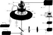
图1为532nm毛细管阵列电泳装置示意图。Figure 1 is a schematic diagram of a 532nm capillary array electrophoresis device.
图2为532nm毛细管阵列电泳装置核心部件剖面图。Fig. 2 is a sectional view of the core components of the 532nm capillary array electrophoresis device.
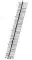
图3为128通道分离若丹明6G的电泳图。Fig. 3 is the electrophoresis diagram of rhodamine 6G separated by 128 channels.
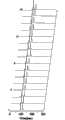
图4为16通道分离若丹明类混合染料的电泳图。Fig. 4 is an electrophoresis diagram of 16-channel separation of rhodamine-based mixed dyes.
具体实施方式Detailed ways
实施例1Example 1
如图1、2所示,一种基于532nm激光诱导荧光检测的多通道模式毛细管电泳装置,它主要由半导体激光器1、光学元件、高压电源10、高压继电器11、毛细管14、缓冲液池、电极12、电流表16、双轴微型直流电机19、第一反射镜5、绝对型旋转编码器17、译码电路22、光电倍增管9、数据采集卡24、计算机23、板25及支柱组成。As shown in Figures 1 and 2, a multi-channel mode capillary electrophoresis device based on 532nm laser-induced fluorescence detection is mainly composed of a
双轴微型直流电机19固定于板25的中心,板25由支柱29支撑固定;双轴微型直流电机19的一轴通过连轴器18与绝对型旋转编码器17连接,绝对型旋转编码器17输出的信号传递给译码电路22,译码电路22再与计算机23线路连接。The biaxial
毛细管14采用圆形对称布局,由刻有均匀凹槽的聚四氟乙烯环20固定,毛细管14的两端分别置于缓冲液池中,其一端由电泳阳极通过继电器11与电泳高压电源10相接,另一端由电泳阴极经电流表16同地相连。The capillary 14 adopts a circular symmetrical layout and is fixed by a
毛细管14阵列的两端分别置于缓冲液池中,其一端置于样品缓冲液池13中,另一端置于共用的缓冲废液池15中,样品缓冲液池13为环形布局,通过可以调节高度的支杆28支撑,支杆28的下端面可在水平面上移动,缓冲废液池15为环形布局,缓冲废液池15放置于环形样品缓冲液池13中部,第一透镜4通过固定环27置于缓冲废液池15的环形中心.固定环27的外周设有外螺纹,缓冲废液池15的内环上加工有内螺纹,固定环27与缓冲废液池15螺纹连接,并可通过螺纹调节其垂直高度.The two ends of the capillary 14 array are respectively placed in the buffer pool, one end is placed in the
转子21由有机玻璃棒经精密机械加工做成,上端铣有矩形凹槽且固定在微型高速直流电机19的下轴上,“V”字形的两平面与水平面的夹角均为45°,其中一平面铣有圆形凹槽,第一反射镜5(500nm-650nm)固定于凹槽内,其反射面与水平面呈45°角,且第一反射镜5置于圆形对称布局毛细管14阵列的中心轴上,中心轴上的第一反射镜5可与圆形对称布局的毛细管14阵列进行相对旋转;第一反射镜5的正下方设置有水平放置的第一透镜4,第一透镜4的正下方设置有与水平面呈45°角的双色镜.3,双色镜3的正下方设置有与水平面呈45°角的第二反射镜2,第二反射镜2置于半导体激光器1的光路上。The
在双色镜3的反射光路上依次设有长通滤波片6、第二透镜7、光阑8,聚焦到光阑8上的荧光信号传递给光电倍增管9检测,光电倍增管9将荧光信号转变为电信号,经12位数据采集卡24A/D转换后,由计算机23存储。A long-pass filter 6, a
聚四氟乙烯环20套在铝环26上,铝环26固定在板25下面的定位槽里,聚四氟乙烯环20由精密机械加工而成,其上均匀刻有128等份凹槽,用于固定毛细管阵列14。The
样品缓冲液池13设计为环形,其上有孔,用于放置缓冲液及样品离心管。毛细管14阵列共用缓冲废液池15,缓冲废液池15深40mm,可以进行重力虹吸进样,样品缓冲液池13由三个支柱28固定,且可以调节,第一透镜4由固定环27固定且垂直可调。The
微型高速直流电机19带动第一反射镜5进行激光扫描,并加快了数据采集的速度;E6CP-AG3C型旋转编码器17读出毛细管14阵列的位置信号,并触发数据采集卡24对该毛细管进行荧光信号采集;半导体激光器1发射的532nm连续激光经第二反射镜2、双色镜3、第一透镜4、第一反射镜5聚焦到毛细管14阵列的检测窗口上,样品产生的荧光由第一反射镜5收集,经第一透镜4变为平行光,双色镜3反射,长通滤波片6滤波,第二透镜7聚焦到光阑8上,并传递给光电倍增管9检测,光电倍增管9将荧光信号转变为电信号,经12位数据采集卡24A/D转换后,由计算机23存储。Miniature high-
以若丹明6G为分析样品验证了128通道毛细管阵列电泳的可行性。采用内径50μm,外径375μm的熔融石英毛细管,总长度为25cm,有效长度为23cm。使用蒸馏水将若丹明6G甲醇母液稀释至1×10⁻⁶mol/L作为分析样品,以含有5%甲醇(v/v)的pH=10,10mmol/L硼砂溶液为运行缓冲液。将128根上述规格的毛细管阵列沿圆形对称地固定在刻有128等份均匀凹槽的聚四氟乙烯环20上,毛细管阵列两端分别置于缓冲溶液池中,阳极通过高压继电器11与电泳高压电源相连接,阴极经电流表16与地相接。将译码电路22上的拨档开关调至128通道位置,系统控制程序中的通道数目设为128。在10kV分离电压下运行缓冲溶液10min后,由继电器11断开电泳高压,电动进样10s,然后进行电泳分离,结果见图3。其中,X轴为若丹明6G的迁移时间,箭头指向为毛细管阵列的通道数目。The feasibility of 128-channel capillary array electrophoresis was verified by using rhodamine 6G as the analysis sample. A fused silica capillary with an inner diameter of 50 μm and an outer diameter of 375 μm is used, with a total length of 25 cm and an effective length of 23 cm. Rhodamine 6G methanol mother liquor was diluted to 1×10⁻⁶ mol/L with distilled water as the analysis sample, and pH=10, 10 mmol/L borax solution containing 5% methanol (v/v) was used as the running buffer. Fix 128 capillary arrays of the above-mentioned specifications symmetrically on a
实施例2Example 2
采用能够输出532nm连续激光的半导体激光器1作为激发光源,其特征为体积小、性能稳定、寿命长、价格低廉,且激光功率可调。A
45度532nm第二反射镜2固定在可调精密光学底座上,便于光路的调节,使激光光束与第一反射镜5同轴,提高了装置的重现性。The 45-degree 532nm
双色镜(550nm以下透过,550nm以上反射)3位于第二反射镜2上方,且与水平面夹角为45°,其作用在于透射532nm激光,同时反射样品产生的荧光并传递给光电倍增管9检测.The dichroic mirror (transmitting below 550nm, reflecting above 550nm) 3 is located above the
转子21由精密机械加工做成,一端为“V”结构,两平面与水平面的夹角均为45°,其中一平面铣有圆形凹槽用于固定第二反射镜(500nm~650nm)5,另一端铣有矩形凹槽且固定在微型高速直流电机19的下轴上。这种设计减弱了高速直流电机工作时的振动,提高了数据的准确性。The
微型高速直流电机19固定在板25上面的定位槽里,它的旋转速度可以调节,旋转方向可以改变,且具有两个旋转轴,上轴通过连轴器18连接绝对型旋转编码器17,下轴连接转子21,外接稳压电源。板25由四个直径为40mm的支柱29固定。The miniature high-
绝对型旋转编码器17由底座定位槽固定,位于直流电机19的上方,并随其旋转。旋转编码器17有八根信号线,工作时输出八种不同的信号,每一种信号对应于一种通道模式,共有八种通道模式,最低为单通道,最高为128通道。旋转编码器17读出毛细管14阵列的位置信号,其位置信号经译码电路22、数据采集卡24传递给计算机23,同时触发数据采集卡24对该毛细管进行荧光信号采集。译码电路22上设有拨档开关,可以对八种不同的通道模式进行选择。这种设计的特征在于可以根据研究的需要选择不同的通道模式,同时旋转编码器17采用格雷码编码,可以比较准确地读出毛细管14阵列的位置信号。The absolute
光电倍增管9外接负高压直流电源,用于荧光信号检测,分析样品产生的荧光由第一反射镜5收集,经第一透镜4变为平行光、双色镜3反射、长通滤波片6滤波、第二透镜7聚焦到光阑8的小孔上,光阑8固定在光电倍增管9上,其前设有可旋转挡光片,光电倍增管9将荧光信号转化为电信号并传递给采集卡24,数据采集卡24将其转变为数字信号后送给计算机。The
聚四氟乙烯环20采用精密机械加工而成,其上刻有128等份凹槽,用于固定毛细管14阵列。聚四氟乙烯环20套在铝环26上,铝环26固定在板25下面的定位槽里。这种设计确保了毛细管14阵列检测窗口到第一反射镜5中心轴线的距离均一致。The
毛细管14阵列呈圆形对称分布,两端分别置于缓冲液池中,并与电极相连接。为了消除毛细管的扭曲张力,便于毛细管的固定,样品池托盘13设计成圆形,其上设有圆形孔,用于放置样品。毛细管14阵列共用废液槽15,其深40mm,放置于样品缓冲液池13的圆形槽中。样品缓冲液池13由三个支柱28固定,且可以调节。第一透镜4由固定环27固定,放置于废液池15的圆形孔中,且沿垂直方向可调。这种设计便于光路调节,同时可以实现重力虹吸进样。The array of
电泳高压电源10通过继电器11与样品池电极12相连,废液池电极经数显式电流表16与地连接。这种设计的特征在于可以有效地进行高压控制,提高了装置的安全性,实现了电动进样,同时通过电流表16显示的电流可以判断电泳缓冲溶液是否发生变化。The electrophoresis high-
激光器、光学元件、光电倍增管、支柱均固定在隔振精密光学平台30上,实现了旋转编码器、高速直流电机、第一反射镜、激光束的共轴,极大地减弱了直流电机工作时的振动,提高了数据的准确、可靠性。Lasers, optical components, photomultiplier tubes, and pillars are all fixed on the vibration-isolation precision optical platform 30, realizing the coaxiality of the rotary encoder, high-speed DC motor, first mirror, and laser beam, which greatly reduces the vibration of the DC motor when it is working. The vibration improves the accuracy and reliability of the data.
采用运行缓冲溶液将若丹明6G、若丹明B的混合物稀释至分析浓度,以pH=9.0,10mmol/L硼砂溶液作为运行缓冲溶液.把16根毛细管(规格与实施例1相同)阵列呈圆形对称地固定在聚四氟乙烯环20上,两端均插入缓冲液池中.将译码电路22上的拨档开关调至16通道位置,系统控制程序中的通道数目设为16.在分离电压13.0kV运行缓冲溶液10min后,由高压继电器11断开电泳高压,在5.0kV电压下电动进样6s,然后在分离电压下进行16通道阵列电泳分离,实验结果见图4.其中,X轴为样品的迁移时间,箭头指向为毛细管通道数目,每个通道的样品峰依次为若丹明6G、若丹明B(由左至右).The mixture of Rhodamine 6G and Rhodamine B was diluted to the analysis concentration by using running buffer solution, with pH=9.0, 10mmol/L borax solution was used as running buffer solution. The array of 16 capillaries (the same specifications as in Example 1) was presented The circle is symmetrically fixed on the
Claims (3)
Priority Applications (1)
| Application Number | Priority Date | Filing Date | Title |
|---|---|---|---|
| CN200610048056ACN101165472B (en) | 2006-10-20 | 2006-10-20 | Multiple-pass mode capillary tube electrophoresis device |
Applications Claiming Priority (1)
| Application Number | Priority Date | Filing Date | Title |
|---|---|---|---|
| CN200610048056ACN101165472B (en) | 2006-10-20 | 2006-10-20 | Multiple-pass mode capillary tube electrophoresis device |
Publications (2)
| Publication Number | Publication Date |
|---|---|
| CN101165472A CN101165472A (en) | 2008-04-23 |
| CN101165472Btrue CN101165472B (en) | 2010-05-12 |
Family
ID=39334250
Family Applications (1)
| Application Number | Title | Priority Date | Filing Date |
|---|---|---|---|
| CN200610048056AExpired - Fee RelatedCN101165472B (en) | 2006-10-20 | 2006-10-20 | Multiple-pass mode capillary tube electrophoresis device |
Country Status (1)
| Country | Link |
|---|---|
| CN (1) | CN101165472B (en) |
Families Citing this family (18)
| Publication number | Priority date | Publication date | Assignee | Title |
|---|---|---|---|---|
| CN101334378B (en)* | 2008-07-29 | 2012-05-16 | 清华大学 | Portable capillary pipe electrophoresis apparatus |
| CN101750450B (en)* | 2008-12-17 | 2013-03-27 | 中国科学院大连化学物理研究所 | Automatic sampling device for array capillary electrophoresis |
| CN101526491B (en)* | 2009-04-16 | 2012-03-21 | 福州大学 | Multi-channel gate of electrochemistry electrode array chip |
| CN102331415B (en)* | 2011-06-15 | 2014-06-04 | 公安部第一研究所 | Method for positioning capillary tube array by using raman spectral imaging |
| CN103234950B (en)* | 2013-05-13 | 2015-01-21 | 上海通微分析技术有限公司 | Parallel dual optical path laser-induced fluorescence spectrograph |
| CN104297155B (en)* | 2014-09-28 | 2016-11-23 | 中国科学院长春光学精密机械与物理研究所 | A kind of multi-channel parallel spectrum investigating system |
| WO2016065073A1 (en)* | 2014-10-22 | 2016-04-28 | Integenx Inc. | Systems and methods for sample preparation, processing and analysis |
| CN105092680B (en)* | 2015-08-18 | 2018-03-27 | 宁波海尔施基因科技有限公司 | Cartridge device applied to HPCE |
| CN106018403B (en)* | 2016-05-12 | 2019-05-21 | 南京擎科生物科技有限公司 | The light absorption detector and detection method of capillary array electrophoresis instrument |
| CN105973860B (en)* | 2016-06-29 | 2019-07-30 | 山东科立森生物股份有限公司 | Capillary electrophoresis detection system and detection method |
| KR102447910B1 (en) | 2016-09-09 | 2022-09-28 | 라이프 테크놀로지스 코포레이션 | Capillary Electrophoresis Cathode System and Method |
| EP3401665A1 (en)* | 2017-05-12 | 2018-11-14 | University College Dublin National University Of Ireland, Dublin | A system and device for analysis of specific matter in liquid samples by optical microscopy |
| CN108593554B (en)* | 2018-05-24 | 2020-10-30 | 大连民族大学 | A multi-dimensionally adjustable laser-induced fluorescence collection and photoelectric conversion device |
| CN108627489B (en)* | 2018-05-24 | 2021-04-13 | 大连民族大学 | A 128-channel array capillary electrophoresis instrument |
| WO2022130606A1 (en)* | 2020-12-18 | 2022-06-23 | 株式会社日立ハイテク | Capillary array electrophoresis device |
| CN113252763A (en)* | 2021-04-21 | 2021-08-13 | 上海应用技术大学 | Multi-channel automatic sample introduction device for capillary electrophoresis fluorescence analysis |
| CN117377867A (en)* | 2021-06-08 | 2024-01-09 | 南京金斯瑞生物科技有限公司 | Detachable capillary clamping of optical element and capillary electrophoresis apparatus |
| CN115308289A (en)* | 2022-09-07 | 2022-11-08 | 桂林电子科技大学 | A capillary electrophoresis system and using method for rapid detection of inorganic explosives |
Citations (3)
| Publication number | Priority date | Publication date | Assignee | Title |
|---|---|---|---|---|
| US20030150727A1 (en)* | 1999-01-27 | 2003-08-14 | Affymetrix, Inc. | Monster capillary array electrophoresis scanner |
| EP1467202A2 (en)* | 2003-04-11 | 2004-10-13 | Hitachi High-Technologies Corporation | Capillary electrophoresis apparatus |
| CN1553168A (en)* | 2003-05-28 | 2004-12-08 | 中国科学院大连化学物理研究所 | Capillary Array Electrophoresis Rotary Laser Scanning Confocal Fluorescence Detector |
- 2006
- 2006-10-20CNCN200610048056Apatent/CN101165472B/ennot_activeExpired - Fee Related
Patent Citations (3)
| Publication number | Priority date | Publication date | Assignee | Title |
|---|---|---|---|---|
| US20030150727A1 (en)* | 1999-01-27 | 2003-08-14 | Affymetrix, Inc. | Monster capillary array electrophoresis scanner |
| EP1467202A2 (en)* | 2003-04-11 | 2004-10-13 | Hitachi High-Technologies Corporation | Capillary electrophoresis apparatus |
| CN1553168A (en)* | 2003-05-28 | 2004-12-08 | 中国科学院大连化学物理研究所 | Capillary Array Electrophoresis Rotary Laser Scanning Confocal Fluorescence Detector |
Also Published As
| Publication number | Publication date |
|---|---|
| CN101165472A (en) | 2008-04-23 |
Similar Documents
| Publication | Publication Date | Title |
|---|---|---|
| CN101165472B (en) | Multiple-pass mode capillary tube electrophoresis device | |
| JP2785530B2 (en) | Electrophoresis device | |
| EP1835281B1 (en) | Multiplexed capillary electrophoresis system | |
| US7090758B2 (en) | Capillary array electrophoresis scanner | |
| US6017765A (en) | Fluorescence detection capillary array electrophoresis analyzer | |
| JP4463228B2 (en) | Optical alignment method and apparatus for capillary electrophoresis apparatus | |
| US20220221406A1 (en) | Sample rotating rack and raman spectrum detector | |
| Fang et al. | A handheld laser-induced fluorescence detector for multiple applications | |
| JP3566207B2 (en) | Rotary confocal scanner for capillary array detection | |
| JP2004505271A (en) | Electrophoresis equipment and plates for it | |
| Zhang et al. | LIFGO: A modular laser-induced fluorescence detection system based on plug-in blocks | |
| CN1235038C (en) | Capillary array electrophoretic ratating laser scanning co-focusing fluorescent inspecting instrument | |
| AU2003219013B2 (en) | Method and device for parallel analysis of bio molecules | |
| Kerékgyártó et al. | Light‐emitting diode induced fluorescence (LED‐IF) detection design for a pen‐shaped cartridge based single capillary electrophoresis system | |
| CN101493413A (en) | Capillary array analyzer by rotating scanning | |
| CN101614652B (en) | Self-aligned optical-fiber fluorescence detection cell and array fluorescence detection cell | |
| CN204314313U (en) | The two addressing multi-channel biochemical analyzer of photoelectricity | |
| CN108627489A (en) | A kind of 128 channel array capillary electrophoresis | |
| Lee et al. | [19] Capillary electrophoresis detectors: Lasers | |
| CN108593554A (en) | It is a kind of can multidimensional adjust laser induced fluorescence collect and photoelectric converting device | |
| JP4975533B2 (en) | Capillary movable instrument and capillary electrophoresis apparatus using the same | |
| CN101196466A (en) | Laser dual-mode micro-volume sample analysis method and device used | |
| JP3296351B2 (en) | Electrophoresis device | |
| JP3042487B2 (en) | Electrophoresis device | |
| JP4177359B2 (en) | Capillary array assembly and capillary electrophoresis apparatus |
Legal Events
| Date | Code | Title | Description |
|---|---|---|---|
| C06 | Publication | ||
| PB01 | Publication | ||
| C10 | Entry into substantive examination | ||
| SE01 | Entry into force of request for substantive examination | ||
| C14 | Grant of patent or utility model | ||
| GR01 | Patent grant | ||
| C17 | Cessation of patent right | ||
| CF01 | Termination of patent right due to non-payment of annual fee | Granted publication date:20100512 Termination date:20131020 |