CN101163856B - Grouped exposing metal heater - Google Patents
Grouped exposing metal heaterDownload PDFInfo
- Publication number
- CN101163856B CN101163856BCN200680013320.4ACN200680013320ACN101163856BCN 101163856 BCN101163856 BCN 101163856BCN 200680013320 ACN200680013320 ACN 200680013320ACN 101163856 BCN101163856 BCN 101163856B
- Authority
- CN
- China
- Prior art keywords
- heater
- temperature
- formation
- ferromagnetic
- stratum
- Prior art date
- Legal status (The legal status is an assumption and is not a legal conclusion. Google has not performed a legal analysis and makes no representation as to the accuracy of the status listed.)
- Expired - Fee Related
Links
Images


Classifications
- E—FIXED CONSTRUCTIONS
- E21—EARTH OR ROCK DRILLING; MINING
- E21B—EARTH OR ROCK DRILLING; OBTAINING OIL, GAS, WATER, SOLUBLE OR MELTABLE MATERIALS OR A SLURRY OF MINERALS FROM WELLS
- E21B43/00—Methods or apparatus for obtaining oil, gas, water, soluble or meltable materials or a slurry of minerals from wells
- E21B43/30—Specific pattern of wells, e.g. optimising the spacing of wells
- C—CHEMISTRY; METALLURGY
- C10—PETROLEUM, GAS OR COKE INDUSTRIES; TECHNICAL GASES CONTAINING CARBON MONOXIDE; FUELS; LUBRICANTS; PEAT
- C10L—FUELS NOT OTHERWISE PROVIDED FOR; NATURAL GAS; SYNTHETIC NATURAL GAS OBTAINED BY PROCESSES NOT COVERED BY SUBCLASSES C10G OR C10K; LIQUIFIED PETROLEUM GAS; USE OF ADDITIVES TO FUELS OR FIRES; FIRE-LIGHTERS
- C10L3/00—Gaseous fuels; Natural gas; Synthetic natural gas obtained by processes not covered by subclass C10G, C10K; Liquefied petroleum gas
- C10L3/06—Natural gas; Synthetic natural gas obtained by processes not covered by C10G, C10K3/02 or C10K3/04
- C10L3/08—Production of synthetic natural gas
- E—FIXED CONSTRUCTIONS
- E21—EARTH OR ROCK DRILLING; MINING
- E21B—EARTH OR ROCK DRILLING; OBTAINING OIL, GAS, WATER, SOLUBLE OR MELTABLE MATERIALS OR A SLURRY OF MINERALS FROM WELLS
- E21B36/00—Heating, cooling or insulating arrangements for boreholes or wells, e.g. for use in permafrost zones
- E21B36/04—Heating, cooling or insulating arrangements for boreholes or wells, e.g. for use in permafrost zones using electrical heaters
- E—FIXED CONSTRUCTIONS
- E21—EARTH OR ROCK DRILLING; MINING
- E21B—EARTH OR ROCK DRILLING; OBTAINING OIL, GAS, WATER, SOLUBLE OR MELTABLE MATERIALS OR A SLURRY OF MINERALS FROM WELLS
- E21B43/00—Methods or apparatus for obtaining oil, gas, water, soluble or meltable materials or a slurry of minerals from wells
- E21B43/16—Enhanced recovery methods for obtaining hydrocarbons
- E21B43/17—Interconnecting two or more wells by fracturing or otherwise attacking the formation
- E—FIXED CONSTRUCTIONS
- E21—EARTH OR ROCK DRILLING; MINING
- E21B—EARTH OR ROCK DRILLING; OBTAINING OIL, GAS, WATER, SOLUBLE OR MELTABLE MATERIALS OR A SLURRY OF MINERALS FROM WELLS
- E21B43/00—Methods or apparatus for obtaining oil, gas, water, soluble or meltable materials or a slurry of minerals from wells
- E21B43/16—Enhanced recovery methods for obtaining hydrocarbons
- E21B43/24—Enhanced recovery methods for obtaining hydrocarbons using heat, e.g. steam injection
- E21B43/2401—Enhanced recovery methods for obtaining hydrocarbons using heat, e.g. steam injection by means of electricity
- H—ELECTRICITY
- H05—ELECTRIC TECHNIQUES NOT OTHERWISE PROVIDED FOR
- H05B—ELECTRIC HEATING; ELECTRIC LIGHT SOURCES NOT OTHERWISE PROVIDED FOR; CIRCUIT ARRANGEMENTS FOR ELECTRIC LIGHT SOURCES, IN GENERAL
- H05B2214/00—Aspects relating to resistive heating, induction heating and heating using microwaves, covered by groups H05B3/00, H05B6/00
- H05B2214/03—Heating of hydrocarbons
Landscapes
- Engineering & Computer Science (AREA)
- Life Sciences & Earth Sciences (AREA)
- Geology (AREA)
- Mining & Mineral Resources (AREA)
- Physics & Mathematics (AREA)
- Environmental & Geological Engineering (AREA)
- Fluid Mechanics (AREA)
- General Life Sciences & Earth Sciences (AREA)
- Geochemistry & Mineralogy (AREA)
- Chemical & Material Sciences (AREA)
- Oil, Petroleum & Natural Gas (AREA)
- General Chemical & Material Sciences (AREA)
- Chemical Kinetics & Catalysis (AREA)
- Organic Chemistry (AREA)
- Production Of Liquid Hydrocarbon Mixture For Refining Petroleum (AREA)
- Resistance Heating (AREA)
- Investigation Of Foundation Soil And Reinforcement Of Foundation Soil By Compacting Or Drainage (AREA)
- Organic Low-Molecular-Weight Compounds And Preparation Thereof (AREA)
- Physical Or Chemical Processes And Apparatus (AREA)
- Measuring Temperature Or Quantity Of Heat (AREA)
- General Induction Heating (AREA)
- Superconductors And Manufacturing Methods Therefor (AREA)
- Electrical Discharge Machining, Electrochemical Machining, And Combined Machining (AREA)
- Surface Heating Bodies (AREA)
- Lubricants (AREA)
- Waste-Gas Treatment And Other Accessory Devices For Furnaces (AREA)
- Auxiliary Devices For And Details Of Packaging Control (AREA)
- Investigating Or Analyzing Materials By The Use Of Fluid Adsorption Or Reactions (AREA)
- Air-Conditioning For Vehicles (AREA)
- Processing Of Solid Wastes (AREA)
- Pipe Accessories (AREA)
- Hydrogen, Water And Hydrids (AREA)
- Communication Control (AREA)
- Treating Waste Gases (AREA)
- Jet Pumps And Other Pumps (AREA)
- Control Of Resistance Heating (AREA)
- Acyclic And Carbocyclic Compounds In Medicinal Compositions (AREA)
- Heat Treatment Of Strip Materials And Filament Materials (AREA)
- Exposure Or Original Feeding In Electrophotography (AREA)
- Gas Separation By Absorption (AREA)
Abstract
Translated fromChineseDescription
Translated fromChinese技术领域technical field
本发明通常涉及用于加热例如含碳氢化合物地层的各种地下地层并由其生产碳氢化合物、氢气和/或其它产物的方法和系统。实施例涉及用于处理含碳氢化合物地层的加热器布局和生产井位置。The present invention generally relates to methods and systems for heating various subterranean formations, such as hydrocarbon-bearing formations, and producing hydrocarbons, hydrogen, and/or other products therefrom. Embodiments relate to heater layouts and production well locations for treating hydrocarbon-bearing formations.
背景技术Background technique
从地下岩层获得的碳氢化合物通常用作能源、原料和消费产品。对可用油气资源耗尽的担忧以及对降低产出的碳氢化合物的综合质量的担忧导致对工艺的改进,以便更有效地提取、加工和/或利用现有油气资源。在现场,可以使用从地下岩层去除碳氢化合物物质的工艺。需要改变地下岩层中的碳氢化合物材料的化学和/或物理性能,从而允许碳氢化合物物质从地下岩层中更容易地去除。化学和物理变化可以包括产出可动流体的就地反应、地层中碳氢化合物物质的成分变化、可溶性变化、密度变化、相变和/或粘度变化。流体可以是(但不限于)气体、液体、乳剂、浆料和/或具有类似于液体流的流动性质的固体颗粒流。Hydrocarbons obtained from underground rock formations are commonly used as energy sources, raw materials and consumer products. Concerns about the depletion of available hydrocarbon resources and concerns about reducing the overall quality of produced hydrocarbons have led to improvements in processes to more efficiently extract, process and/or utilize existing hydrocarbon resources. In the field, processes for removing hydrocarbon substances from subterranean formations may be used. There is a need to alter the chemical and/or physical properties of hydrocarbon materials in subterranean formations to allow easier removal of hydrocarbon species from subterranean formations. Chemical and physical changes may include in situ reactions producing mobile fluids, changes in composition, solubility changes, density changes, phase changes, and/or viscosity changes of hydrocarbon species in the formation. Fluids may be, but are not limited to, gases, liquids, emulsions, slurries, and/or streams of solid particles having flow properties similar to liquid streams.
加热器可以放置在井眼中以在就地工艺中加热地层。授权给Ljungstrom美国专利No.2,634,961,授权给Ljungstrom的美国专利No.2,732,195,授权给Ljungstrom的美国专利No.2,780,450,授权给Ljungstrom的美国专利No.2,789,805,授权给Ljungstrom的2,923,535,授权给Van Meurs et al的美国专利No.4,886,118显示说明了利用井下加热器的就地工艺的实例。Heaters may be placed in the wellbore to heat the formation in an in situ process. U.S. Patent No. 2,634,961 to Ljungstrom, U.S. Patent No. 2,732,195 to Ljungstrom, U.S. Patent No. 2,780,450 to Ljungstrom, U.S. Patent No. 2,789,805 to Ljungstrom, 2,923,535 to Ljungstrom, Van Meurs et US Patent No. 4,886,118 to al shows an example of an in situ process utilizing downhole heaters.
授权给Ljungstrom的美国专利No.2,923,535和授权给Van Meurs etal的美国专利No.4,886,118描述了对油页岩地层加热的应用。可以给油页岩地层加热以使油页岩地层中的油母岩质热解。热量还可以破坏地层以提高地层的穿透性。增大的穿透性可以允许地层流体流向使流体从油页岩地层中去除的生产井。在由Ljungstrom公开的一些工艺中,例如,含氧气态介质导入渗透层(优选地,仍然由于预热步骤保持热度)以开始燃烧。US Patent Nos. 2,923,535 to Ljungstrom and 4,886,118 to Van Meurs et al describe the application of heating to oil shale formations. Heat may be applied to the oil shale formation to pyrolyze kerogen in the oil shale formation. Heat can also damage the formation to increase the penetration of the formation. Increased permeability may allow formation fluids to flow to production wells where fluids are removed from the oil shale formation. In some processes disclosed by Ljungstrom, for example, an oxygen-containing gaseous medium is introduced into the permeate layer (preferably still warm due to the preheating step) to initiate combustion.
热源可用于加热地下岩层。电加热器可用于通过辐射和/或传导加热地下岩层。电加热器可有阻抗地加热元件。授权给Germain的美国专利No.2,548,360描述了放入井眼内粘性油中的电热元件。加热元件加热油并使其变稀以允许油从井眼抽出。授权给Eastlund et al.的美国专利No.4,716,960描述了通过使相对低压电流流过管线来电加热石油井管线,从而防止固体形成。授权给Van Egmond的美国专利No.5,065,818描述了粘结到井孔中的电热元件,没有围绕加热元件的套管。A heat source may be used to heat a subterranean formation. Electric heaters can be used to heat subterranean formations by radiation and/or conduction. Electric heaters can resistively heat the element. US Patent No. 2,548,360 to Germain describes an electric heating element placed in viscous oil within a wellbore. The heating element heats and thins the oil to allow it to be pumped from the wellbore. US Patent No. 4,716,960 to Eastlund et al. describes electrically heating oil well tubing by passing a relatively low voltage current through the tubing to prevent solids from forming. US Patent No. 5,065,818 issued to Van Egmond describes an electric heating element bonded into a wellbore, without a casing surrounding the heating element.
授权给Vinegar et al.的美国专利No.6,023,554描述了位于套管中的电热元件。加热元件产生加热套管的辐射能。粒状固体填充材料可以放在套管和地层之间。套管可以传导地加热填充材料,其继而传导地加热地层。暴露金属加热器可以使电流泄漏到地层中。电流泄漏到地层中可以导致地层中不希望和/或不均匀加热。因此,有利地是提供这样一种加热装置,其沿加热器的长度提供均匀的热量;有效地加热表层以下的地层;和/或抑制加热器之间的电流泄漏和抑制电流泄漏到地层中。U.S. Patent No. 6,023,554 to Vinegar et al. describes an electric heating element located in a sleeve. The heating element produces radiant energy that heats the sleeve. Granular solid fill material may be placed between the casing and the formation. The casing may conductively heat the fill material, which in turn conductively heats the formation. Exposed metal heaters can allow electrical current to leak into the formation. Leakage of electrical current into the formation may result in unwanted and/or uneven heating in the formation. Accordingly, it would be advantageous to provide a heating arrangement that provides uniform heat along the length of the heater; efficiently heats the subsurface formation; and/or inhibits current leakage between heaters and into the formation.
发明内容Contents of the invention
这里描述的实施例通常涉及用于处理地下地层的系统、方法和加热器。这里描述的实施例还通常涉及内部具有新颖部件的加热器。这种加热器可以通过使用此处描述的系统和方法获得。Embodiments described herein generally relate to systems, methods, and heaters for treating subterranean formations. Embodiments described herein also generally relate to heaters with novel components inside. Such heaters can be obtained using the systems and methods described herein.
在一些实施例中,本发明提供了一种用于处理含碳氢化合物地层的系统,包括:两组或多组伸长加热器,其中一组包括放入地层中的两个或多个开口内的两个或多个加热器,组内加热器在地层表面以下电气耦联,所述开口包括位于地层的碳氢化合物层中的至少部分暴露的井眼;所述组电气配置成使流过位于至少两组之间的地层的电流得到抑制;并且,加热器配置成给地层提供热量。In some embodiments, the present invention provides a system for treating a hydrocarbon-bearing formation comprising: two or more sets of elongate heaters, one set including two or more openings placed into the formation two or more heaters within a set electrically coupled below the surface of the formation, the opening comprising an at least partially exposed wellbore in a hydrocarbon layer of the formation; the set electrically configured such that the flow Current flow through the formation located between the at least two sets is inhibited; and, the heater is configured to provide heat to the formation.
在特定实施例中,本发明提供一个或多个系统、方法和/或加热器。In certain embodiments, the present invention provides one or more systems, methods and/or heaters.
在一些实施例中,所述系统、方法和/或加热器用于处理地下地层。In some embodiments, the systems, methods and/or heaters are used to treat subterranean formations.
在进一步的实施例中,特定实施例的特征可以与其它实施例的特征组合。例如,一个实施例的特征可以与任意其它实施例的特征组合。In further embodiments, features of certain embodiments may be combined with features of other embodiments. For example, features of one embodiment may be combined with features of any other embodiment.
在进一步的实施例中,利用这里描述的任意方法、系统或加热器进行对地下地层的处理。In further embodiments, the treatment of a subterranean formation is performed using any of the methods, systems, or heaters described herein.
在进一步的实施例中,附加特征可以加到这里描述的特定实施例中。In further embodiments, additional features may be added to certain embodiments described herein.
附图说明Description of drawings
对于本领域的普通技术人员来说,通过阅读下列详细说明并参考附图可以使本发明的优点变得显而易见,其中:Advantages of the present invention will become apparent to those of ordinary skill in the art upon reading the following detailed description, in conjunction with the accompanying drawings, in which:
图1显示了加热含碳氢化合物地层的阶段的实例。Figure 1 shows an example of the stages of heating a hydrocarbon-bearing formation.
图2显示了用于处理含碳氢化合物地层的现场转化系统的一部分的实例的示意图。Figure 2 shows a schematic diagram of an example of a portion of an in situ conversion system for treating a hydrocarbon containing formation.
图3、4和5显示了具有外部导体的温度限制加热器的实例的横截面视图,所述外部导体具有铁磁部分和非铁磁部分。Figures 3, 4 and 5 show cross-sectional views of examples of temperature-limited heaters with an outer conductor having ferromagnetic and non-ferromagnetic portions.
图6A和6B显示了温度限制加热器的实例的横截面视图。6A and 6B show cross-sectional views of examples of temperature limited heaters.
图7显示了温度限制加热器的实例,其中,在温度低于铁磁导体的居里温度时,支撑构件提供大部分热输出。Figure 7 shows an example of a temperature limited heater where the support member provides most of the heat output at temperatures below the Curie temperature of the ferromagnetic conductor.
图8和9显示了温度限制加热器的实施例,其中在温度低于铁磁导体的居里温度时,护套提供大部分热输出。Figures 8 and 9 show an embodiment of a temperature limited heater in which the sheath provides most of the heat output at temperatures below the Curie temperature of the ferromagnetic conductor.
图10显示了以三相配置耦联在一起的温度限制加热器的实施例。Figure 10 shows an embodiment of temperature limited heaters coupled together in a three phase configuration.
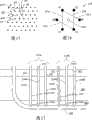
图11显示了以三相配置耦联的三个加热器的实施例。Figure 11 shows an embodiment of three heaters coupled in a three phase configuration.
图12显示了大体上U形三相加热器的实施例的侧视图。Figure 12 shows a side view of an embodiment of a generally U-shaped three-phase heater.
图13显示了位于地层中的多个三元结构的三相加热器的实施例的顶视图。Figure 13 shows a top view of an embodiment of a plurality of three-phase heaters in a ternary structure located in a formation.
图14显示了带有生产井的图13所示实施例的顶视图。Figure 14 shows a top view of the embodiment shown in Figure 13 with production wells.
图15显示了六边形的多个三元结构的三相加热器的实施例的顶视图。Figure 15 shows a top view of an embodiment of a three-phase heater in a hexagonal multiple ternary structure.
图16显示了图15所示六边形结构的实施例的顶视图。FIG. 16 shows a top view of the embodiment of the hexagonal structure shown in FIG. 15 .
图17显示了三元结构耦联到水平连接井上的实施例。Figure 17 shows an embodiment of a ternary structure coupled to a horizontal connecting well.
图18显示了利用图11和13所示加热器和加热器布局进行STARS模拟得出的累积产气量和累积产油量对时间的图表。Figure 18 shows a graph of cumulative gas production and cumulative oil production versus time from a STARS simulation using the heaters and heater layout shown in Figures 11 and 13.
尽管本发明易于存在多种改进和可选形式,但是本发明的特定实施例将作为实例显示于附图中并在此进行详细说明。附图未按比例绘制。但是,应当理解,附图及其详细说明不是将本发明限制于所公开的特定形式,相反地,本发明涵盖落入如所附权利要求限定的本发明的精神和范围之内的所有改进,等效物和可选方案。While the invention is susceptible to various modifications and alternative forms, certain embodiments of the invention are shown by way of example in the drawings and described in detail herein. The figures are not drawn to scale. It should be understood, however, that the drawings and their detailed description are not to limit the invention to the particular form disclosed, but on the contrary, the invention covers all modifications falling within the spirit and scope of the invention as defined by the appended claims, Equivalents and Alternatives.
具体实施方式Detailed ways
下列说明通常涉及用于处理地层中的碳氢化合物的系统和方法。可以处理这种地层以生产烃类产品、氢气和其它产物。The following description generally relates to systems and methods for processing hydrocarbons in a formation. Such formations can be processed to produce hydrocarbon products, hydrogen, and other products.
“碳氢化合物”通常解释为主要由碳原子和氢原子组成的分子。碳氢化合物还可以包括其它元素,例如但不限于,卤素、金属元素、氮、氧和/或硫。碳氢化合物可以是(但不限于)油母岩质、沥青、焦性沥青、油、天然矿物蜡和沥青岩。碳氢化合物可能位于地下矿物母岩中或与其相邻。母岩可以包括但不限于沉积岩、矿砂、硅质生物岩、碳酸盐、硅藻岩和其它多孔介质。“碳氢化合物流体”是包括碳氢化合物的流体。碳氢化合物流体可以包括、夹带或被夹带在非烃流体中,所述非烃流体例如为氢气、氮气、一氧化碳、二氧化碳、硫化氢、水和氨。"Hydrocarbons" are generally interpreted as molecules consisting primarily of carbon and hydrogen atoms. Hydrocarbons may also include other elements such as, but not limited to, halogens, metallic elements, nitrogen, oxygen, and/or sulfur. Hydrocarbons may be, but are not limited to, kerogen, bitumen, pyrobitumen, oil, natural mineral wax, and bituminous rock. Hydrocarbons may be located in or adjacent to subsurface mineral matrix. Host rocks may include, but are not limited to, sedimentary rocks, mineral sands, siliceous biorocks, carbonates, diatomites, and other porous media. A "hydrocarbon fluid" is a fluid comprising hydrocarbons. Hydrocarbon fluids may include, entrain, or be entrained in non-hydrocarbon fluids such as hydrogen, nitrogen, carbon monoxide, carbon dioxide, hydrogen sulfide, water, and ammonia.
“地层”包括一或多个含碳氢化合物层,一或多个非烃层、上覆岩层和/或下伏岩层。“上覆岩层”和/或“下伏岩层”包括一或多种不同类型的不渗透物质。例如,上覆岩层和/或下伏岩层可以包括岩石、页岩、泥岩或湿/致密碳酸盐。在现场转化工艺的一些实施例中,上覆岩层和/或下伏岩层可以包括含碳氢化合物层,它们是相对不渗透的,并且在导致上覆岩层和/或下伏岩层的含碳氢化合物层发生显著的特征变化的现场转化工艺过程中不受温度影响。例如,下伏岩层可以包含页岩或泥岩,但是下伏岩层在现场转化工艺期间不允许加热到热解温度。在有些情况下,上覆岩层和/或下伏岩层可以具有一些渗透性。A "formation" includes one or more hydrocarbon-bearing layers, one or more non-hydrocarbon layers, overburdens and/or underburdens. An "overburden" and/or "underburden" includes one or more different types of impermeable materials. For example, an overburden and/or an underburden may include rock, shale, mudstone, or wet/tight carbonate. In some embodiments of an in-situ conversion process, the overburden and/or underburden may include hydrocarbon-bearing formations that are relatively impermeable and that contribute to hydrocarbon-containing formations in the overburden and/or underburden. The in-situ conversion process in which the compound layer undergoes significant characteristic changes is not affected by temperature. For example, an underburden may contain shale or mudstone, but the underburden is not allowed to heat to pyrolysis temperatures during the in-situ conversion process. In some cases, the overburden and/or the underburden may have some permeability.
“加热器”是用于在井内或接近井眼的区域内产生热量的任何系统或热源。加热器可以是(但不限于)与地层中或由地层产生的物质或其组合发生反应的电加热器、燃烧器、燃烧室。A "heater" is any system or heat source used to generate heat in a wellbore or in a region near the wellbore. The heater may be, but is not limited to, an electric heater, a burner, a combustion chamber that reacts with substances in or produced by the formation, or a combination thereof.
“现场转化工艺”是指通过热源加热含碳氢化合物地层以将至少一部分地层的温度提高至热解温度以上,以便在地层中产生热解流体的工艺。"In situ conversion process" means a process in which a hydrocarbon-containing formation is heated by a heat source to raise the temperature of at least a portion of the formation above the pyrolysis temperature to produce pyrolysis fluids in the formation.
“绝缘导体”是指能够导电并且全部或部分地由电气绝缘材料包覆的任何伸长材料。"Insulated conductor" means any elongate material capable of conducting electricity and which is wholly or partially covered with an electrically insulating material.
伸长构件可以是裸露金属加热器或暴露金属加热器。“裸露金属”和“暴露金属”是指不包括例如矿物绝缘层的电气绝缘层的金属,所述电气绝缘层设计成在伸长构件的所有工作温度范围内给金属提供电气绝缘。裸露金属和暴露金属可以包括具有腐蚀抑制剂的金属,所述腐蚀抑制剂例如为天然产生的氧化层、施加的氧化层和/或薄膜。裸露金属和暴露金属包括具有聚合或其它类型电气绝缘的金属,所述电气绝缘在伸长构件的典型工作温度下不能保持电气绝缘性质。这种物质可以放在金属上,并且在使用加热器期间可能发生热解。The elongate member may be a bare metal heater or an exposed metal heater. "Bare metal" and "exposed metal" refer to metal that does not include an electrical insulating layer, such as a mineral insulating layer, designed to provide electrical insulation to the metal over the entire operating temperature range of the elongate member. Bare metal and exposed metal may include metals with corrosion inhibitors, such as naturally occurring oxide layers, applied oxide layers, and/or films. Bare metal and exposed metal include metals that have polymeric or other types of electrical insulation that do not maintain electrical insulating properties at typical operating temperatures of the elongate member. This substance can be placed on metal and pyrolysis may occur during use of the heater.
“温度限制加热器”通常是指在不使用例如调温器、功率调节器、整流器或其它装置的情况下,将热输出调节(例如,减小热输出)到规定温度以上的加热器。温度限制加热器可以是AC(交流)或调制(例如,“斩波”)DC(直流)供电的电阻加热器。A "temperature limited heater" generally refers to a heater that regulates (eg, reduces heat output) above a specified temperature without the use of, for example, a thermostat, power regulator, rectifier, or other device. The temperature limited heater may be an AC (alternating current) or modulated (eg, "chopped") DC (direct current) powered resistive heater.
“居里温度”是指在该温度以上使铁磁材料丧失其全部铁磁性质的温度。除了在高于居里温度时丧失全部铁磁性质,在增大的电流流过铁磁材料时,铁磁材料也开始丧失铁磁性质。"Curie temperature" means the temperature above which a ferromagnetic material loses all of its ferromagnetic properties. In addition to losing all ferromagnetic properties above the Curie temperature, ferromagnetic materials also begin to lose their ferromagnetic properties when increasing current is passed through them.
“时变电流”是指在铁磁导体中产生趋肤效应电荷流并且具有随时间变化的大小的电流。时变电流包括交流(AC)和调制直流(DC)。"Time-varying current" refers to a current that produces a skin-effect charge flow in a ferromagnetic conductor and that has a magnitude that varies with time. Time-varying currents include alternating current (AC) and modulated direct current (DC).
“交流(AC)”是指大体上沿正弦方向翻转的时变电流。交流在铁磁导体中产生趋肤效应电荷流。"Alternating current (AC)" refers to a time-varying current that reverses in a generally sinusoidal direction. AC creates a skin effect charge flow in a ferromagnetic conductor.
“调制直流(DC)”是指在铁磁导体中产生趋肤效应电荷流的任何大体上非正弦的时变电流。"Modulated direct current (DC)" refers to any substantially non-sinusoidal, time-varying current that produces a skin-effect charge flow in a ferromagnetic conductor.
温度限制加热器的“调节比”是指对于给定电流而言,低于居里温度时的最高交流或调制直流电阻与高于居里温度时的最低电阻的比率。The "turndown ratio" of a temperature limited heater is the ratio of the highest AC or modulated DC resistance below the Curie temperature to the lowest resistance above the Curie temperature for a given current.
在减少的热输出加热系统、设备和方法的范围内,术语“自动地”是指这种系统、设备和方法在不使用外部控制(例如,诸如具有温度传感器和反馈回路的控制器、PID控制器或预测控制器的外部控制器)的情况下以特定方式工作。In the context of reduced heat output heating systems, devices and methods, the term "automatically" means that such systems, devices and methods operate without the use of external controls (e.g., such as controllers with temperature sensors and feedback loops, PID controls controllers or external controllers to predictive controllers) work in a specific way.
术语“井眼”是指通过钻入地层或将管道插入地层而在地层中形成的孔。井眼具有大体上圆形横截面,或其它横截面形状。当在此使用时,术语“井”和“开口”在指地层中的开口时可与术语“井眼”互换使用。The term "wellbore" refers to a hole formed in a formation by drilling into the formation or inserting a pipe into the formation. The wellbore has a generally circular cross-section, or other cross-sectional shape. As used herein, the terms "well" and "opening" are used interchangeably with the term "wellbore" when referring to an opening in a formation.
“三元结构(Triad)”是指一组三个耦联在一起的物品(例如,加热器,井眼或其它物体)。"Triad" refers to a set of three items (eg, heaters, boreholes, or other objects) that are coupled together.
地层中的碳氢化合物可以多种方式进行处理以产出多种不同的产物。在特定实施例中,地层中的碳氢化合物分阶段地处理。图1显示了加热含碳氢化合物地层的阶段的实例。图1还显示了以每吨的当量油桶数(y轴)为单位的由地层产出的地层流体产量(“Y”)对以摄氏温度(x轴)为单位的受热地层的温度(“T”)的实例。Hydrocarbons in a formation can be processed in a variety of ways to produce a variety of different products. In certain embodiments, hydrocarbons in the formation are processed in stages. Figure 1 shows an example of the stages of heating a hydrocarbon-bearing formation. Figure 1 also shows formation fluid production ("Y") produced by the formation in units of barrels of oil equivalent per ton (y-axis) versus the temperature of the heated formation in degrees Celsius (x-axis) (" T") instance.
在阶段1加热期间发生甲烷解吸和水汽化。阶段1的地层加热可以尽可能快地进行。例如,当首先加热含碳氢化合物地层时,地层中的碳氢化合物解吸被吸附的甲烷。从地层中可以产出被解吸的甲烷。如果含碳氢化合物地层进一步加热,含碳氢化合物地层中的水汽化。在一些含碳氢化合物地层中,水可能占据地层中10%-50%的孔隙空间。在其它地层中,水占据更多或更少的孔隙空间。水典型地在绝对压力为600kPa到7000kPa,温度为160到285℃的地层中汽化。在一些实施例中,汽化水产生地层中的可湿度变化和/或增大的地层压力。可湿度变化和/或增大的压力可能影响地层中的热解反应或其它反应。在特定实施例中,汽化水从地层中产生。在其它实施例中,汽化水用于地层中或地层外的蒸汽提取和/或蒸馏。从地层中去除水以及增加地层中的孔隙空间可以增大地层中碳氢化合物的存储空间。Methane desorption and water vaporization occur during
在特定实施例中,在阶段1加热之后,地层进一步受热,使得地层中的温度(至少)达到初始热解温度(例如阶段2所示温度范围的下限温度)。地层中的碳氢化合物可在阶段2期间热解。热解温度范围根据地层中碳氢化合物的类型而改变。热解温度范围可以包括250到900℃。用于生产希望产物的热解温度范围可以只贯穿总热解温度范围的一部分。在一些实施例中,用于生产希望产物的热解温度范围可以为250到400℃或者270到350℃。如果地层中碳氢化合物的温度在250到400℃的温度范围内缓慢升高,在温度达到400℃时,热解产物的生产基本完成。碳氢化合物的平均温度可以在用于生产希望产物的热解温度范围内以小于5℃/天,小于2℃/天,小于1℃/天,或小于0.5℃/天的速率升高。利用多个热源加热含碳氢化合物地层可以在热源周围建立热梯度,所述热源使地层中碳氢化合物的温度在热解温度范围内缓慢升高。In certain embodiments, after
用于生产希望产物的热解温度范围内的增温率可能影响由含碳氢化合物地层产出的地层流体的数量和质量。在用于生产希望产物的热解温度范围内缓慢升高温度可能抑制地层中长链分子的活化。在用于生产希望产物的热解温度范围内缓慢升高温度可能限制生产非希望产物的活化碳氢化合物之间的反应。在用于希望产物的热解温度范围内缓慢升高地层温度可能允许从地层中生产高质量、高API重度的碳氢化合物。在用于希望产物的热解温度范围内缓慢升高地层温度可能允许去除存在于地层中作为碳氢化合物产物的大量碳氢化合物。The rate of warming over the pyrolysis temperature range used to produce desired products can affect the quantity and quality of formation fluids produced from a hydrocarbon-bearing formation. Slowly increasing the temperature within the range of pyrolysis temperatures used to produce the desired product may inhibit the activation of long chain molecules in the formation. Slowly increasing the temperature within the range of pyrolysis temperatures used to produce the desired product may limit the reaction between activated hydrocarbons to produce the undesired product. Slowly increasing the formation temperature within the pyrolysis temperature range for the desired product may allow the production of high quality, high API gravity hydrocarbons from the formation. Slowly increasing the temperature of the formation within the pyrolysis temperature range for the desired product may allow removal of significant amounts of hydrocarbons present in the formation as hydrocarbon products.
在一些现场转化实施例中,一部分地层加热到希望的温度,以代替在温度范围内缓慢加热。在一些实施例中,希望的温度是300℃,325℃或350℃。可以选择其它温度作为希望的温度。来自热源的热量叠加允许在地层中相对迅速、有效地产生希望的温度。可以调节从热源输入到地层中的能量以将地层中的温度大体保持在希望的温度。地层的受热部分大体上保持在希望的温度,直到热解作用减弱到使从地层中生产希望的地层流体变得不经济。进行热解作用的一部分地层可以包括只通过来自一个热源的热传递达到热解温度范围的区域。In some in situ conversion embodiments, a portion of the formation is heated to a desired temperature instead of slowly heating over a temperature range. In some embodiments, the desired temperature is 300°C, 325°C or 350°C. Other temperatures may be selected as desired. The superimposition of heat from the heat source allows the desired temperature to be generated in the formation relatively quickly and efficiently. Energy input into the formation from the heat source may be adjusted to maintain the temperature in the formation substantially at a desired temperature. The heated portion of the formation is generally maintained at the desired temperature until pyrolysis abates to such an extent that it becomes uneconomical to produce the desired formation fluids from the formation. A portion of the formation undergoing pyrolysis may include regions that reach the pyrolysis temperature range only by heat transfer from one heat source.
在特定实施例中,地层流体包括由地层生产的热解流体。当地层温度升高时,产出的地层流体中的可凝结碳氢化合物的数量可能减少。高温下,地层可能主要产出甲烷和/或氢气。如果含碳氢化合物地层始终在整个热解范围内加热,地层在接近热解范围上限时可能只生产少量氢气。在所有可用氢气耗尽之后,通常发生最小量的流体生产。In certain embodiments, the formation fluids include pyrolysis fluids produced by the formation. As formation temperatures increase, the amount of condensable hydrocarbons in produced formation fluids may decrease. At high temperatures, formations may primarily produce methane and/or hydrogen. If a hydrocarbon-bearing formation is heated throughout the pyrolysis range, the formation may produce only small amounts of hydrogen near the upper end of the pyrolysis range. Minimal fluid production typically occurs after all available hydrogen is exhausted.
在碳氢化合物热解之后,大量碳和一部分氢气可能仍然存在于地层中。保留在地层中的大部分碳可以合成气体的形式从地层中产出。在图1所示的阶段3加热期间可以发生合成气体生产。阶段3可以包括将含碳氢化合物地层加热到足以发生合成气体生产的温度。例如,合成气体可以在400到1200℃、500到1100℃或550到1000℃的温度范围内产出。地层受热部分的温度在合成气体产生流体引入地层时确定在地层中产出的合成气体的成分。生成的合成气体可以通过生产井从地层中去除。Substantial amounts of carbon and some hydrogen may still be present in the formation after hydrocarbon pyrolysis. Most of the carbon remaining in the formation can be produced from the formation in the form of synthesis gas. Synthesis gas production can occur during
由含碳氢化合物地层产出的流体的总能含量可以在热解和合成气体生产期间保持相对稳定。在较低地层温度下发生热解期间,大部分产出流体可能是具有高能含量的可凝结碳氢化合物。但是,在较高热解温度下,少量地层流体可能包括可凝结碳氢化合物。更多的不凝结地层流体可以从地层中产出。产出流体每单位体积的能含量可能在主要生产不凝结地层流体期间略有下降。在合成气体生产期间,产出合成气体每单位体积的能含量与热解流体的能含量相比显著下降。但是,产出合成气体的体积在许多情况下显著增大,从而补偿降低的能含量。The total energy content of fluids produced from hydrocarbon-bearing formations may remain relatively constant during pyrolysis and synthesis gas production. During pyrolysis at lower formation temperatures, most of the produced fluids are likely to be condensable hydrocarbons with high energy content. However, at higher pyrolysis temperatures, small amounts of formation fluids may include condensable hydrocarbons. More noncondensable formation fluids can be produced from the formation. The energy content per unit volume of produced fluids may decrease slightly during the period of primary production of non-condensing formation fluids. During synthesis gas production, the energy content per unit volume of the produced synthesis gas decreases significantly compared to the energy content of the pyrolysis fluid. However, the volume of synthesis gas produced is in many cases significantly increased in order to compensate for the reduced energy content.
图2显示了用于处理含碳氢化合物地层的现场转化系统的一部分的实施例的示意图。现场转化系统可以包括隔离井200。隔离井用于形成处理区域周围的隔离。隔离井防止流体流入和/或流出处理区域。隔离井包括但不限于脱水井、真空井、俘获井、注入井、水泥浆井、冷冻井或其组合。在一些实施例中,隔离井200是脱水井。脱水井可以去除液态水和/或防止液态水进入要加热地层的一部分,或进入正加热地层。在图2所示实施例中,隔离井200显示为只沿热源202的一侧延伸,但是隔离井典型地围绕所用或要使用的所有热源202以加热地层的处理区域。Figure 2 shows a schematic diagram of an embodiment of a portion of an in situ conversion system for treating a hydrocarbon containing formation. The on-site conversion system may include an
热源202放在地层的至少一部分中。热源202可以包括加热器,例如绝缘导体、管道内导体加热器、表面燃烧器、无焰分布式燃烧室和/或天然分布式燃烧室。热源202还可以包括其它类型的加热器。热源202给地层的至少一部分提供热量以加热地层中的碳氢化合物。能量可以通过供给管线204提供给热源202。供给管线204根据用于加热地层的热源类型而在结构上有所不同。用于热源的供给管线204可以传输用于电加热器的电能,可以输送用于燃烧室的燃料,或者可以输送在地层中循环的热交换流体。A
生产井206用于从地层中去除地层流体。在一些实施例中,生产井206可以包括一或多个热源。生产井中的热源可以加热位于生产井中或其附近的地层的一或多个部分。生产井中的热源可以防止从地层中去除的地层流体发生凝结和回流。
从生产井206中产出的地层流体可以通过收集管线208输送给处理设备210。地层流体也可以由热源202生产。例如,流体可以由热源202生产以控制邻近热源的地层中的压力。由热源202生产的流体可以通过管道或管线输送给收集管线208,或者产出流体可以通过管道或管线直接输送给处理设备210。处理设备210可以包括分离单元、反应单元、提质加工单元、燃料电池、涡轮机、存储容器和/或用于加工产出的地层流体的其它系统与单元。处理设备可以从由地层产出的碳氢化合物的至少一部分中形成运输燃料。Formation fluid produced from production well 206 may be delivered to
温度限制加热器可以包含在配置中和/或可以包括在特定温度下给加热器提供自动温度限制性质的材料。在特定实施例中,温度限制加热器中使用铁磁材料。铁磁材料在温度等于或接近材料的居里温度时自我限制温度,以在时变电流施加给材料时,在温度等于或接近居里温度的情况下提供减小的热量。在特定实施例中,铁磁材料在大约等于居里温度的选定温度下自我限制温度限制加热器的温度。在特定实施例中,选定温度为居里温度的35℃以内、25℃以内、20℃以内或10℃以内。在特定实施例中,铁磁材料与其它材料(例如,高传导材料、高强度材料、耐腐蚀材料或其组合)结合以提供各种电气和/或机械性能。温度限制加热器的一些部件与温度限制加热器的其它部分相比可以具有较低的电阻(起因于不同的几何结构和/或使用不同的铁磁材料和/或非铁磁材料)。使温度限制加热器的一部分具有不同材料和/或尺寸允许从加热器的每一部分产生希望的热输出。A temperature limiting heater may be included in the arrangement and/or may include materials that provide the heater with automatic temperature limiting properties at specific temperatures. In certain embodiments, ferromagnetic materials are used in temperature limited heaters. Ferromagnetic materials are self-limiting in temperature at or near the Curie temperature of the material to provide reduced heat at or near the Curie temperature when a time-varying current is applied to the material. In particular embodiments, the ferromagnetic material self-limits the temperature of the temperature-limiting heater at a selected temperature approximately equal to the Curie temperature. In particular embodiments, the selected temperature is within 35°C, within 25°C, within 20°C, or within 10°C of the Curie temperature. In certain embodiments, ferromagnetic materials are combined with other materials (eg, highly conductive materials, high strength materials, corrosion resistant materials, or combinations thereof) to provide various electrical and/or mechanical properties. Some components of the temperature-confined heater may have lower electrical resistance (due to different geometries and/or use of different ferromagnetic and/or non-ferromagnetic materials) than other parts of the temperature-confined heater. Having portions of the temperature limited heater of different materials and/or dimensions allows a desired heat output to be generated from each portion of the heater.
温度限制加热器比其它加热器更加可靠。温度限制加热器不容易因地层中的热点而中止或失效。在一些实施例中,温度限制加热器允许大体上均匀地加热地层。在一些实施例中,温度限制加热器通过沿加热器的整个长度以较高的平均热输出操作而更为有效地加热地层。如果沿加热器任一点的温度超过或要超过加热器的最高工作温度,因为加热器功率无须像典型的恒定瓦特加热器那样在整个加热器范围内减小,使得温度限制加热器可以沿加热器的整个长度在较高的平均热输出下操作。来自温度限制加热器的一部分且接近加热器居里温度的热输出自动减小,而无需给加热器施加时变电流进行控制。热输出由于温度限制加热器的一部分的电气性质(例如,电阻)的改变而自动减小。因此,在加热过程的大部分时间内,温度限制加热器提供了更多的能量。Temperature limited heaters are more reliable than other heaters. Temperature limited heaters are less prone to abort or failure due to hot spots in the formation. In some embodiments, the temperature limited heater allows for substantially uniform heating of the formation. In some embodiments, temperature limited heaters heat the formation more efficiently by operating at a higher average heat output along the entire length of the heater. If the temperature at any point along the heater exceeds or is about to exceed the maximum operating temperature of the heater, since the heater power does not have to be reduced across the entire heater range like a typical constant watt heater, the temperature limiting heater can Operates at a higher average heat output throughout its length. Heat output from a portion of the temperature-limited heater approaching the Curie temperature of the heater is automatically reduced without control by applying a time-varying current to the heater. Heat output is automatically reduced due to a change in electrical properties (eg, resistance) of a portion of the temperature limiting heater. Therefore, the temperature limited heater provides more energy during most of the heating process.
在特定实施例中,当给温度限制加热器施加时变电流时,在温度接近、等于或高于加热器电阻部分的居里温度时,包括温度限制加热器的系统首先提供第一热输出,随后提供减小的(第二热输出)热输出。第一热输出是温度限制加热器开始自我限制的温度以下的热输出。在一些实施例中,第一热输出是温度限制加热器中铁磁材料在居里温度以下50℃、75℃、100℃或125℃温度的热输出。In a particular embodiment, when a time-varying current is applied to the temperature-limited heater, the system comprising the temperature-limited heater first provides a first heat output at a temperature near, equal to, or above the Curie temperature of the resistive portion of the heater, A reduced (second heat output) heat output is then provided. The first heat output is the heat output below the temperature at which the temperature limiting heater begins to limit itself. In some embodiments, the first heat output is the heat output of the ferromagnetic material in the temperature limited heater at a temperature of 50°C, 75°C, 100°C or 125°C below the Curie temperature.
温度限制加热器可以由在井头处提供的时变电流(交流或调制直流)激励。井头可以包括电源和用于给温度限制加热器提供能量的其它部件(例如,调制元件、变压器和/或电容器)。温度限制加热器可以是用于加热地层一部分的许多加热器之一。The temperature limited heater can be energized by a time-varying current (AC or modulated DC) provided at the wellhead. The wellhead may include a power supply and other components (eg, modulating elements, transformers, and/or capacitors) for powering the temperature-limited heater. A temperature limited heater may be one of many heaters used to heat a portion of the formation.
在特定实施例中,温度限制加热器包括导体,当时变电流提供给导体时,该导体起到趋肤效应或邻近效应加热器的作用。趋肤效应限制电流透入导体内部的深度。对于铁磁体来说,趋肤效应由导体导磁率控制。铁磁体的相对导磁率典型地为10到1000(例如,铁磁体的相对导磁率典型地为至少10,可以是至少50,100,500,1000或更大)。当铁磁材料的温度上升到居里温度以上或者施加的电流增大时,铁磁材料的导磁率大大降低,并且趋肤深度迅速扩大(例如,透入深度以导磁率的平方根倒数扩大)。当温度接近、等于或高于居里温度和/或施加的电流增大时,导磁率的减小导致导体的交流或调制直流电阻减小。当温度限制加热器由大体上恒流电源供电时,接近、达到或高于居里温度的加热器部分具有减少的热耗散。不等于或接近居里温度的温度限制加热器部分可以由趋肤效应加热控制,所述趋肤效应加热允许加热器由于较高的电阻负荷而具有高热耗散。In certain embodiments, the temperature limited heater includes a conductor that acts as a skin effect or proximity effect heater when a time varying current is supplied to the conductor. The skin effect limits the depth to which current can penetrate into the interior of a conductor. For ferromagnets, the skin effect is controlled by the permeability of the conductor. Ferromagnets typically have a relative permeability of 10 to 1000 (eg, ferromagnets typically have a relative permeability of at least 10, and may be at least 50, 100, 500, 1000 or more). When the temperature of the ferromagnetic material rises above the Curie temperature or the applied current increases, the magnetic permeability of the ferromagnetic material decreases greatly and the skin depth expands rapidly (eg, the penetration depth expands with the inverse square root of the magnetic permeability). The decrease in magnetic permeability results in a decrease in the AC or modulated DC resistance of the conductor as the temperature approaches, equals, or exceeds the Curie temperature and/or the applied current increases. When the temperature limited heater is powered by a substantially constant current source, portions of the heater near, at or above the Curie temperature have reduced heat dissipation. Temperature limited heater sections that are not at or near the Curie temperature can be controlled by skin effect heating that allows the heater to have high heat dissipation due to higher resistive loads.
使用温度限制加热器加热地层中碳氢化合物的优点是所选导体具有处于希望的工作温度范围内的居里温度。在希望的工作温度范围内操作允许大量热量注入地层,同时将温度限制加热器和其它设备的温度保持在设计极限温度以下。设计极限温度是产生例如腐蚀、蠕动和/或变形的性质的温度。温度限制加热器的温度限制特性防止邻近地层中低导热率“热点”的加热器过热或烧坏。在一些实施例中,根据加热器中所用材料,温度限制加热器能够在高于25℃、37℃、100℃、250℃、550℃、700℃、800℃、900℃或高至1131℃的温度下降低或控制热输出和/或耐热。An advantage of using temperature limited heaters to heat hydrocarbons in the formation is that the conductors are selected to have a Curie temperature within the desired operating temperature range. Operating within the desired operating temperature range allows a significant amount of heat to be injected into the formation while maintaining the temperature of temperature-limited heaters and other equipment below design limits. The design limit temperature is the temperature at which properties such as corrosion, creep and/or deformation occur. Temperature Limiting The temperature limiting feature of the heater prevents heaters adjacent to low thermal conductivity "hot spots" in the formation from overheating or burning out. In some embodiments, depending on the materials used in the heater, the temperature limited heater can operate at temperatures above 25°C, 37°C, 100°C, 250°C, 550°C, 700°C, 800°C, 900°C, or as high as 1131°C Temperature reduction or control of heat output and/or heat resistance.
因为输入到温度限制加热器中的能量无须限制于适应邻近加热器的低导热率区域,所以与恒定瓦特加热器相比,温度限制加热器允许向地层中注入更多的能量。例如,在Green River油页岩中,最低富油页岩层和最高富油页岩层的热传导率之间存在至少为3倍的差异。当加热这种地层时,与受限于低导热率层温度的传统加热器相比,利用温度限制加热器可以给地层输送显著增多的热量。沿传统加热器整个长度的热输出需要适应低导热率层,使得加热器不会在低导热率层中过热或烧化。对于温度限制加热器来说,邻近高温下低导热率层的热输出将减少,但是不处于高温下的温度限制加热器的剩余部分将保持提供高热输出。因为用于加热碳氢化合物地层的加热器典型地很长(例如,至少10米,100米,300米,至少500米,1千米,或长至10千米),温度限制加热器的大部分长度可以在居里温度以下工作,而只有一小部分长度在温度等于或接近温度限制加热器的居里温度的情况下工作。Temperature limited heaters allow more energy to be injected into the formation than constant watt heaters because the energy input into the temperature limited heater does not have to be limited to accommodate low thermal conductivity regions adjacent to the heater. For example, in the Green River oil shale, there is at least a 3-fold difference in thermal conductivity between the lowest and highest oil-rich shale formations. When heating such formations, the use of temperature-limited heaters can deliver significantly more heat to the formation than conventional heaters that are limited by the temperature of the low thermal conductivity layer. The heat output along the entire length of a conventional heater needs to accommodate the low thermal conductivity layer so that the heater does not overheat or burn out in the low thermal conductivity layer. For a temperature limited heater, the heat output adjacent to the low thermal conductivity layer at high temperature will decrease, but the remainder of the temperature limited heater not at high temperature will keep providing high heat output. Because heaters used to heat hydrocarbon formations are typically very long (e.g., at least 10 meters, 100 meters, 300 meters, at least 500 meters, 1 kilometer, or as long as 10 kilometers), temperature limits the size of the heater. Part of the length can be operated below the Curie temperature, while only a small part of the length can be operated at or near the Curie temperature of the temperature limiting heater.
使用温度限制加热器允许有效地将热量输送给地层。有效传热允许减少将地层加热到希望温度所需要的时间。例如,在Green River油页岩中,在利用传统的恒定瓦特加热器使用12米加热器井距时,热解典型地需要9.5到10年的加热时间。对于相同的加热器间距来说,温度限制加热器允许较大的平均热输出,同时将加热设备温度保持在设备设计极限温度以下。与由恒定瓦特加热器提供的较低平均热输出相比,在由温度限制加热器提供的较大平均热输出情况下,地层中的热解可以在更早的时刻发生。例如,在Green River油页岩中,使用具有12米加热器井距的温度限制加热器,热解可以存在5年。温度限制加热器抵消由于不准确井距或在加热器井过于密集的地方钻孔引起的热点。在特定实施例中,温度限制加热器允许对间隔过大的加热器井随时间加大能量输出,或者对过于密集布置的加热器井限制能量输出。温度限制加热器还在邻近上覆岩层和下伏岩层之间的区域内提供较多热量以补偿这些区域内的温度损失。The use of temperature limited heaters allows efficient delivery of heat to the formation. Efficient heat transfer allows reducing the time required to heat the formation to a desired temperature. For example, in the Green River oil shale, pyrolysis typically requires a heating time of 9.5 to 10 years using conventional constant watt heaters using a 12-meter heater well spacing. For the same heater spacing, temperature limited heaters allow for a greater average heat output while maintaining the heating device temperature below the device design limit temperature. With a greater average heat output provided by a temperature-limited heater, pyrolysis in the formation can occur at an earlier time than with a lower average heat output provided by a constant watt heater. For example, in the Green River oil shale, pyrolysis can exist for 5 years using temperature-limited heaters with a heater well spacing of 12 m. Temperature limited heaters counteract hot spots caused by inaccurate well spacing or drilling where heater wells are too densely populated. In certain embodiments, temperature limited heaters allow the energy output to be ramped up over time for heater wells that are too widely spaced, or to limit the energy output for heater wells that are too densely arranged. Temperature limited heaters also provide more heat in areas between adjacent overburden and underburden to compensate for temperature losses in these areas.
温度限制加热器有利地在许多类型的地层中使用。例如,在含沥青砂地层或含重质烃类的相对渗透的地层中,温度限制加热器可提供可控低温输出,以便减小液体粘度、活性流体、和/或增强井眼处或附近或着地层中的径向流体流。温度限制加热器可用于防止由于地层的近井眼区域过热导致的过度焦化地层生成。Temperature limited heaters are advantageously used in many types of formations. For example, in tar sands-bearing formations or relatively permeable formations containing heavy hydrocarbons, temperature-limited heaters can provide controlled low-temperature output to reduce fluid viscosity, activate fluids, and/or enhance Radial fluid flow in the formation. Temperature limited heaters may be used to prevent excessively coked formations from overheating near the wellbore region of the formation.
在一些实施例中,使用温度限制加热器消除或减少了对昂贵温度控制线路的需要。例如,使用温度限制加热器消除或减少进行温度测井的需要和/或使用位于加热器上的固定热电偶监视热点处潜在过热的需要。In some embodiments, the use of temperature limited heaters eliminates or reduces the need for expensive temperature control wiring. For example, the use of temperature limited heaters eliminates or reduces the need to conduct temperature logging and/or the need to monitor potential overheating at hot spots using fixed thermocouples located on the heater.
在特定实施例中,温度限制加热器耐变形。井眼中物质的定位运动可能在加热器上产生使其形状变形的横向应力。沿着加热器长度且井眼接近或靠近加热器的位置可能是热点,在所述热点处,标准加热器过热并且具有烧坏的可能。这些热点可能降低金属的屈服强度和蠕变强度,导致加热器压碎或变形。温度限制加热器可以形成为S曲线(或其它非线性形状),其适应温度限制加热器的变形而不会导致加热器故障。In certain embodiments, the temperature limited heater is resistant to deformation. Positional movement of material in the wellbore may create lateral stresses on the heater that distort its shape. Locations along the length of the heater and in the wellbore close to or near the heater may be hot spots where standard heaters overheat and have the potential to burn out. These hot spots can reduce the yield and creep strength of the metal, causing the heater to crush or deform. The temperature limited heater can be formed as an S-curve (or other non-linear shape) that accommodates deformation of the temperature limited heater without causing heater failure.
在一些实施例中,温度限制加热器可以比标准加热器更经济地生产或制造。典型的铁磁材料包括铁、碳钢或铁素体不锈钢。这种材料与在绝缘导体(矿物绝缘电缆)加热器中使用的镍基加热合金(例如,镍铬合金,KanthalTM(Bulten-Kanthal AB,Sweden),和/或LOHMTM(Driver-Harris Company,Harrison,New Jersey,U.S.A))相比更为便宜。在温度限制加热器的一个实施例中,温度限制加热器以连续长度的形式制造为绝缘导体加热器,从而降低成本和提高可靠性。In some embodiments, temperature limited heaters may be more economically produced or manufactured than standard heaters. Typical ferromagnetic materials include iron, carbon steel or ferritic stainless steel. This material is compatible with nickel-based heating alloys used in insulated conductor (mineral insulated cable) heaters (e.g., Nichrome, Kanthal™ (Bulten-Kanthal AB, Sweden), and/or LOHM™ (Driver-Harris Company, Harrison, New Jersey, USA)) are cheaper. In one embodiment of the temperature limited heater, the temperature limited heater is manufactured as an insulated conductor heater in a continuous length, thereby reducing cost and increasing reliability.
在一些实施例中,温度限制加热器利用盘管装置放在加热器井中。可以盘绕在卷轴上的加热器可以通过使用金属,例如铁素体不锈钢(例如,409不锈钢)制成,所述铁素体不锈钢利用电阻焊(ERW)焊接。为了形成加热器部分,来自滚筒机的金属条穿过第一成形设备,其中所述金属条成形为管状,随后利用ERW进行纵焊。所述管子穿过第二成形设备,其中,导电带材(例如,铜带材)被施加、通过模具紧密收缩到管子上,并利用ERW进行纵焊。通过将支撑材料(例如,诸如347H或347HH的钢)纵焊到传导带材上形成护层。支撑材料可以是卷绕在传导带材上的带材。加热器的覆盖部分可以类似的方式形成。在特定实施例中,覆盖部分使用诸如304不锈钢或316不锈钢的非铁磁性材料代替铁磁材料。加热器部分和覆盖部分可以使用标准技术,例如使用轨道焊接装置的对接焊连接在一起。在一些实施例中,覆盖部分材料(非铁磁性材料)可以在卷绕之前预焊接到铁磁材料上。预焊接可以消除对单独连接步骤(例如,对接焊)的需要。在实施例中,可以在形成管式加热器之后拉动柔性电缆(例如,诸如MGT1000熔炉电缆的熔炉电缆(furnace cable))穿过中心。柔性电缆上的端部衬套可以焊接到管式加热器上以提供电流返回通路。包括柔性电缆的管式加热器可以在安装到加热器井中之前盘绕到卷轴上。在实施例中,温度限制加热器利用盘管装置安装。盘管装置可以将温度限制加热器放在地层中的防变形容器内。防变形容器可以利用常规方法放入加热器井中。In some embodiments, the temperature limited heater is placed in the heater well using a coil arrangement. The heater, which may be coiled on a reel, may be made by using metal, such as ferritic stainless steel (eg, 409 stainless steel), which is welded using electric resistance welding (ERW). To form the heater section, a metal strip from a roller machine is passed through a first forming apparatus, wherein the metal strip is formed into a tubular shape and subsequently longitudinally welded using ERW. The tube passes through a second forming apparatus where conductive tape (eg copper tape) is applied, shrunk tightly onto the tube through a die, and longitudinally welded using ERW. The sheath is formed by longitudinal welding of a support material (for example, steel such as 347H or 347HH) to the conductive strip. The support material may be a tape wound on a conductive tape. The covering portion of the heater can be formed in a similar manner. In certain embodiments, the covering portion uses a non-ferromagnetic material such as 304 stainless steel or 316 stainless steel instead of a ferromagnetic material. The heater section and cover section may be joined together using standard techniques such as butt welding using an orbital welding setup. In some embodiments, the cover portion material (non-ferromagnetic material) may be pre-welded to the ferromagnetic material prior to winding. Pre-welding can eliminate the need for a separate joining step (eg, butt welding). In an embodiment, a flexible cable (eg, a furnace cable such as the MGT1000 furnace cable) may be pulled through the center after the tubular heater is formed. End bushings on the flex cable can be welded to the tube heater to provide a current return path. Tubular heaters including flexible cables may be coiled onto reels prior to installation in heater wells. In an embodiment, the temperature limited heater is installed using a coil unit. The coil unit may place temperature limited heaters in a deformation resistant container in the formation. The anti-deformation container can be placed in the heater well using conventional methods.
在温度限制加热器中使用的铁磁性合金或铁磁性合金决定加热器的居里温度。用于各种金属的居里温度数据记录于“American Institute ofPhysics Handbook”,第二版,McGraw-Hill,5-170到5-176页中。铁磁导体可以包括一种或多种铁磁元素(铁,钴和镍)和/或这些元素的合金。在一些实施例中,铁磁导体包括含有钨(W)的铁铬(Fe-Cr)合金(例如,HCM12A和SAVE12(Sumitomo Metals Co.,Japan))和/或含有铬的铁合金(例如,Fe-Cr合金,Fe-Cr-W合金,Fe-Cr-V(钒)合金,Fe-Cr-Nb(铌)合金)。在三种主要的铁磁元素中,铁具有770℃的居里温度;钴(Co)具有1131℃的居里温度;镍具有大约358℃的居里温度。铁钴合金的居里温度高于铁的居里温度。例如,具有2%wt(重量百分比)钴的铁钴合金的居里温度为800℃;具有12%wt钴的铁钴合金的居里温度为900℃;具有20%wt钴的铁钴合金的居里温度为950℃。铁镍合金的居里温度低于铁的居里温度。例如,具有20%wt镍的铁镍合金的居里温度为720℃,具有60%wt镍的铁镍合金的居里温度为560℃。The ferromagnetic alloy or ferromagnetic alloy used in a temperature limited heater determines the Curie temperature of the heater. Curie temperature data for various metals are recorded in the "American Institute of Physics Handbook", Second Edition, McGraw-Hill, pages 5-170 to 5-176. Ferromagnetic conductors may comprise one or more ferromagnetic elements (iron, cobalt and nickel) and/or alloys of these elements. In some embodiments, ferromagnetic conductors include iron-chromium (Fe-Cr) alloys containing tungsten (W) (e.g., HCM12A and SAVE12 (Sumitomo Metals Co., Japan)) and/or iron alloys containing chromium (e.g., Fe-Cr). -Cr alloy, Fe-Cr-W alloy, Fe-Cr-V (vanadium) alloy, Fe-Cr-Nb (niobium) alloy). Among the three main ferromagnetic elements, iron has a Curie temperature of 770°C; cobalt (Co) has a Curie temperature of 1131°C; and nickel has a Curie temperature of about 358°C. The Curie temperature of iron-cobalt alloy is higher than that of iron. For example, the Curie temperature of an iron-cobalt alloy with 2%wt (weight percent) cobalt is 800°C; the Curie temperature of an iron-cobalt alloy with 12%wt cobalt is 900°C; The Curie temperature is 950°C. The Curie temperature of iron-nickel alloy is lower than that of iron. For example, an iron-nickel alloy with 20%wt nickel has a Curie temperature of 720°C, and an iron-nickel alloy with 60%wt nickel has a Curie temperature of 560°C.
用作合金的一些非铁磁元素提高了铁的居里温度。例如,具有5.9%wt钒的铁钒合金的居里温度为大约815℃。其它非铁磁元素(例如,碳铝,铜,硅和/或铬)可以与铁或其它铁磁材料形成合金以降低居里温度。提高居里温度的非铁磁性材料可以与降低居里温度的非铁磁性材料结合以及与铁或其它铁磁材料形成合金以制造具有希望的居里温度和其它希望的物理和/或化学性质的材料。在一些实施例中,居里温度材料是例如NiFe2O4的铁酸盐。在其它实施例中,居里温度材料是例如FeNi3或Fe3Al的二元化合物。Some non-ferromagnetic elements used as alloys raise the Curie temperature of iron. For example, an iron-vanadium alloy with 5.9 wt% vanadium has a Curie temperature of approximately 815°C. Other non-ferromagnetic elements (eg, carbon aluminum, copper, silicon and/or chromium) can be alloyed with iron or other ferromagnetic materials to lower the Curie temperature. Non-ferromagnetic materials that raise the Curie temperature can be combined with non-ferromagnetic materials that lower the Curie temperature and alloyed with iron or other ferromagnetic materials to produce a material having a desired Curie temperature and other desired physical and/or chemical properties. Material. In some embodiments, the Curie temperature material is a ferrite such as NiFe2 O4 . In other embodiments, the Curie temperature material is a binary compound such asFeNi3 orFe3Al .
温度限制加热器的特定实施例可以包括一种以上的铁磁材料。如果这里描述的所有情况应用于温度限制加热器中的至少一种铁磁材料,这种实施例包含在此处所述实施例的范围之内。Certain embodiments of temperature limited heaters may include more than one ferromagnetic material. Such embodiments are included within the scope of the embodiments described herein if all of the conditions described herein apply to at least one ferromagnetic material in a temperature-limited heater.
铁磁性质通常在接近居里温度时下降。由C.James Erickson(IEEEPress,1995)撰写的“Handbook of Electrical Heating for Industry”显示了用于1%碳钢(具有1%wt碳的钢)的标准曲线。导磁率损失开始于650℃以上的温度,并且在温度超过730℃时趋于完成。因此,自限制温度会略低于铁磁导体的实际居里温度。1%碳钢内用于电流的趋肤深度在室温下为0.132厘米,在720℃下增大到0.445厘米。从720到730℃,趋肤深度迅速增大到2.5厘米以上。因此,使用1%碳钢的温度限制加热器实施例在650到730℃之间开始自我限制。Ferromagnetic properties generally decline as the Curie temperature is approached. The "Handbook of Electrical Heating for Industry" by C. James Erickson (IEEE Press, 1995) shows a standard curve for 1% carbon steel (steel with 1% wt carbon). Permeability loss begins at temperatures above 650°C and tends to complete at temperatures above 730°C. Therefore, the self-limiting temperature will be slightly lower than the actual Curie temperature of the ferromagnetic conductor. The skin depth for electric current in 1% carbon steel is 0.132 cm at room temperature and increases to 0.445 cm at 720 °C. From 720 to 730°C, the skin depth increases rapidly to more than 2.5 cm. Thus, the temperature limiting heater embodiment using 1% carbon steel begins to limit itself between 650 and 730°C.
趋肤深度通常定义了时变电流进入传导材料中的有效透入深度。一般而言,电流密度随着沿导体半径从外表面向中心的距离呈指数规律减小。电流密度等于表面电流密度的大致1/e的深度称作趋肤深度。对于直径远大于透入深度的实心圆柱杆,或者对于具有超过透入深度的壁厚的空心圆柱体来说,趋肤深度δ等于:Skin depth generally defines the effective penetration depth of a time-varying electrical current into a conducting material. In general, the current density decreases exponentially with the distance along the conductor radius from the outer surface to the center. The depth at which the current density is equal to approximately 1/e of the surface current density is called the skin depth. For a solid cylindrical rod with a diameter much greater than the penetration depth, or for a hollow cylinder with a wall thickness exceeding the penetration depth, the skin depth δ is equal to:
(1)δ=1981.5*(ρ/(μ*f))1/2(1) δ=1981.5*(ρ/(μ*f))1/2
其中:δ=趋肤深度(英寸);Where: δ = skin depth (inches);
ρ=工作温度下的电阻(欧姆·厘米);ρ = resistance at working temperature (ohm cm);
μ=相对导磁率;和μ = relative permeability; and
f=频率(赫兹)。f = frequency (Hz).
由C.James Erickson(IEEE Press,1995)撰写的“Handbook ofElectrical Heating for Industry”中得到等式1。对于大多数金属而言,电阻(ρ)随时间增大。相对导磁率通常随温度和电流变化。附加等式可用于估算导磁率和/或趋肤深度随温度和/或电流的变化。由μ对磁场的关系导出μ对电流的关系。
可以选择温度限制加热器中的所用材料以提供希望的调节比。对温度限制加热器可以选择至少1.1∶1,2∶1,3∶1,4∶1,5∶1,10∶1,30∶1或50∶1的调节比。还可以使用更大的调节比。选定的调节比可能取决于许多因素,这些因素包括但不限于安放温度限制加热器的地层类型(例如,较大的调节比可用于油页岩地层,其中富油页岩层和贫油页岩层之间的热传导率具有很大不同)和/或井眼中所用材料的温度极限(例如,加热器材料的温度极限)。在一些实施例中,通过使附加铜或其它良导体结合到铁磁材料中(例如,添加铜以降低高于居里温度时的电阻)增大调节比。The materials used in the temperature limiting heater can be selected to provide the desired turndown ratio. A turndown ratio of at least 1.1:1, 2:1, 3:1, 4:1, 5:1, 10:1, 30:1 or 50:1 can be selected for the temperature limiting heater. Larger turndown ratios may also be used. The selected turndown ratio may depend on many factors including, but not limited to, the type of formation in which the temperature limiting heater is placed (e.g., larger turndown ratios may be used in oil shale formations, where oil-rich shale formations and oil-poor shale formations There is a large difference in thermal conductivity between the two) and/or the temperature limits of the materials used in the wellbore (for example, the temperature limits of the heater material). In some embodiments, the turndown ratio is increased by incorporating additional copper or other good conductors into the ferromagnetic material (eg, adding copper to reduce resistance above the Curie temperature).
温度限制加热器可以在低于加热器的居里温度时提供最小热输出(功率输出)。在特定实施例中,最小热输出为至少400W/m(瓦特/米),600W/m,700W/m,800W/m或高至2000W/m。当加热器的一部分的温度接近或高于居里温度时,温度限制加热器减少了该部分加热器的热输出量。减少的热量可以充分小于居里温度以下的热输出。在一些实施例中,减小的热量为至多400W/m,200W/m,100W/m或可能接近0W/m。A temperature limited heater can provide a minimum heat output (power output) below the Curie temperature of the heater. In particular embodiments, the minimum heat output is at least 400W/m (watts/meter), 600W/m, 700W/m, 800W/m or up to 2000W/m. A temperature limiting heater reduces the heat output of a portion of the heater when the temperature of that portion is near or above the Curie temperature. The heat reduction may be substantially less than the heat output below the Curie temperature. In some embodiments, the reduced heat is at most 400 W/m, 200 W/m, 100 W/m or possibly close to 0 W/m.
在一些实施例中,调节交流频率以改变铁磁材料的趋肤深度。例如,在室温下,1%碳钢的趋肤深度为60赫兹下0.132厘米,180赫兹下0.0762厘米,440赫兹下0.046厘米。因为加热器直径典型地大于趋肤深度的两倍,使用较高频率(和由此形成的具有较小直径的加热器)可以降低加热器成本。对于固定几何结构来说,较高的频率产生较大的调节比。较高频率下的调节比通过使较低频率下的调节比与较高频率除以较低频率的平方根相乘而得出。在一些实施例中,使用100到1000赫兹,140到200赫兹,或400到600赫兹的频率(例如,180赫兹,540赫兹或720赫兹)。在一些实施例中,可以使用高频率。频率可以大于1000赫兹。In some embodiments, the AC frequency is adjusted to change the skin depth of the ferromagnetic material. For example, at room temperature, 1% carbon steel has a skin depth of 0.132 cm at 60 Hz, 0.0762 cm at 180 Hz, and 0.046 cm at 440 Hz. Since the heater diameter is typically greater than twice the skin depth, the use of higher frequencies (and thus heaters with smaller diameters) can reduce heater cost. For a fixed geometry, a higher frequency yields a larger turndown ratio. The turndown ratio at the higher frequency is obtained by multiplying the turndown ratio at the lower frequency by the square root of dividing the higher frequency by the lower frequency. In some embodiments, a frequency of 100 to 1000 Hz, 140 to 200 Hz, or 400 to 600 Hz (eg, 180 Hz, 540 Hz, or 720 Hz) is used. In some embodiments, high frequencies may be used. The frequency can be greater than 1000 Hz.
在特定实施例中,调制直流(例如,斩波直流,波形调制直流或循环直流)可用于给温度限制加热器提供电能。直流调制器或直流斩波器可与直流电源相联以提供调制直流输出。在一些实施例中,直流电源可以包括用于调制直流的装置。直流调制器的一个实例是直流-直流变换器系统。直流-直流变换器系统在本领域中通常已知。直流典型地调制或斩波为希望的波形。用于直流调制的波形包括但不限于方波、正弦波、变形正弦波、变形方波、三角形波、和其它规则或不规则波形。In certain embodiments, modulated direct current (eg, chopped direct current, waveform modulated direct current, or circulating direct current) may be used to power a temperature-limited heater. A DC modulator or DC chopper can be connected to the DC power supply to provide a modulated DC output. In some embodiments, the DC power supply may include means for modulating the DC. An example of a DC modulator is a DC-DC converter system. DC-DC converter systems are generally known in the art. The DC is typically modulated or chopped to the desired waveform. Waveforms for DC modulation include, but are not limited to, square waves, sine waves, deformed sine waves, deformed square waves, triangular waves, and other regular or irregular waveforms.
调制直流波形通常定义了调制直流的频率。因此,可以选择调制直流波形以提供希望的调制直流频率。调制直流波形的调制形状和/或速率(例如,斩波速率)可以变化以改变调制直流频率。直流可在频率高于常用交流频率的情况下调制。例如,调制直流可以在至少1000赫兹的频率下提供。将馈送电流的频率提高到较高值有利地增大温度限制加热器的调节比。The modulating DC waveform generally defines the frequency at which the DC is modulated. Thus, the modulating DC waveform can be selected to provide the desired modulating DC frequency. The modulation shape and/or rate (eg, chopping rate) of the modulating DC waveform can be varied to change the modulating DC frequency. DC can be modulated at frequencies higher than commonly used AC frequencies. For example, modulated direct current may be provided at a frequency of at least 1000 Hz. Increasing the frequency of the feed current to a higher value advantageously increases the turndown ratio of the temperature limited heater.
在特定实施例中,调节或改变调制直流波形以改变调制直流频率。直流调制器能够在使用温度限制加热器期间的任何时刻和在高电流或电压下对调制直流波形进行调节或改变。因此,提供给温度限制加热器的调制直流不限于单频率乃至频率值的小集合。使用直流调制器进行波形选择典型地允许大范围调制直流频率和调制直流频率的离散控制。因此,调制直流频率更容易设置在离散值,而交流频率通常限制到多个行频(line frequency)。调制直流频率的离散控制允许对温度限制加热器的调节比进行更多的选择控制。能够选择控制温度限制加热器的调节比允许大量材料用于设计和构造温度限制加热器。In a particular embodiment, the modulating DC waveform is adjusted or changed to change the modulating DC frequency. The DC modulator is capable of adjusting or changing the modulated DC waveform at any time during use of the temperature limited heater and at high current or voltage. Thus, the modulated direct current supplied to a temperature limited heater is not limited to a single frequency or even a small set of frequency values. Waveform selection using a DC modulator typically allows a wide range of modulation DC frequencies and discrete control of the modulation DC frequency. Thus, modulating DC frequencies are easier to set at discrete values, whereas AC frequencies are usually limited to multiple line frequencies. Discrete control of the modulated DC frequency allows more selective control over the turndown ratio of the temperature limiting heater. Being able to selectively control the turndown ratio of the temperature limiting heater allows for a large number of materials to be used in the design and construction of the temperature limiting heater.
在一些实施例中,调节调制直流频率或交流频率以补偿在使用期间温度限制加热器的性质(例如,地下情况,例如温度或压力)变化。根据估算的井下条件改变提供给温度限制加热器的调制直流频率或交流频率。例如,当井眼中温度限制加热器的温度增加时,有利地是增大提供给加热器的电流频率,从而增大加热器的调节比。在实施例中,估计井眼中温度限制加热器的井下温度。In some embodiments, the modulated DC frequency or AC frequency is adjusted to compensate for changes in the properties of the temperature limiting heater (eg, subsurface conditions such as temperature or pressure) during use. The modulated DC or AC frequency supplied to the temperature limited heater is varied based on estimated downhole conditions. For example, as the temperature of a temperature-limited heater in the wellbore increases, it may be advantageous to increase the frequency of the current supplied to the heater, thereby increasing the turn-down ratio of the heater. In an embodiment, the downhole temperature of a temperature limiting heater in the wellbore is estimated.
在特定实施例中,改变调制直流频率或交流频率以调节温度限制加热器的调节比。可以调节调节比以补偿沿温度限制加热器长度出现的热点。例如,因为温度限制加热器在特定位置变得过热,从而使调节比增大。在一些实施例中,在不估计地下状况的情况下,改变调制直流频率或交流频率以调节调节比。In certain embodiments, the modulation DC frequency or AC frequency is varied to adjust the turndown ratio of the temperature limiting heater. The turndown ratio can be adjusted to compensate for hot spots that occur along the length of the temperature limiting heater. For example, the turndown ratio is increased because the temperature limits the heater from becoming too hot at a particular location. In some embodiments, the modulating DC frequency or AC frequency is varied to adjust the turndown ratio without estimating subsurface conditions.
在特定实施例中,为耐腐蚀性、屈服强度和/或抗蠕变性选择温度限制加热器的最外层(例如外部导体)。在一个实施例中,在外部导体中可以使用奥氏体(非铁磁性)不锈钢,例如201,304H,347H,347HH,316H,310H,347HP,NF709(Nippon Steel Corp.,Japan)不锈钢或其组合。最外层还可以包括包覆金属的导体。例如,为了在铁磁碳钢管上进行防腐,可以包覆例如800H或347H不锈钢的耐腐蚀合金。如果不要求耐高温强度,最外层可以由具有良耐腐蚀性的铁磁金属,例如铁素体不锈钢之一构造而成。在一个实施例中,具有82.3%wt铁,17.7%wt铬的铁素体合金(居里温度为678℃)提供希望的耐腐蚀性。In certain embodiments, the outermost layer (eg, outer conductor) of the temperature-limited heater is selected for corrosion resistance, yield strength, and/or creep resistance. In one embodiment, an austenitic (non-ferromagnetic) stainless steel such as 201, 304H, 347H, 347HH, 316H, 310H, 347HP, NF709 (Nippon Steel Corp., Japan) stainless steel or combinations thereof may be used in the outer conductor . The outermost layer may also include a metal-clad conductor. For example, for corrosion protection on ferromagnetic carbon steel pipe, a corrosion resistant alloy such as 800H or 347H stainless steel may be clad. If high temperature strength is not required, the outermost layer may be constructed from one of ferromagnetic metals having good corrosion resistance, such as ferritic stainless steel. In one embodiment, a ferritic alloy with 82.3%wt iron, 17.7%wt chromium (Curie temperature of 678°C) provides desirable corrosion resistance.
Metals Handbook,第8卷,291页(American Society of Materials(ASM))包括铁铬合金的居里温度对合金中铬量的图表。在一些温度限制加热器实施例中,单独的支撑杆或管(由347H不锈钢制成)耦联到由铁铬合金制成的温度限制加热器上以提供屈服强度和/或抗蠕变性。在特定实施例中,选择支持材料和/或铁磁材料以提供650℃下,至少20.7MPa的100,000小时蠕变断裂强度。在一些实施例中,100,000小时蠕变断裂强度是650℃下至少13.8MPa,或者650℃下至少6.9MPa。例如,347H钢在温度等于或高于650℃时具有良好的蠕变断裂强度。在一些实施例中,对于更长的加热器和/或更高的地应力或流体应力来说具有从6.9MPa到41.3MPa或以上的100,000小时蠕变断裂强度。The Metals Handbook, Vol. 8, p. 291 (American Society of Materials (ASM)) includes a graph of the Curie temperature for iron-chromium alloys versus the amount of chromium in the alloy. In some temperature limiting heater embodiments, a separate support rod or tube (made of 347H stainless steel) is coupled to a temperature limiting heater made of iron chrome to provide yield strength and/or creep resistance. In particular embodiments, the support material and/or ferromagnetic material is selected to provide a 100,000 hour creep rupture strength of at least 20.7 MPa at 650°C. In some embodiments, the 100,000 hour creep rupture strength is at least 13.8 MPa at 650°C, or at least 6.9 MPa at 650°C. For example, 347H steel has good creep rupture strength at temperatures equal to or higher than 650°C. In some embodiments, 100,000 hour creep rupture strength from 6.9 MPa to 41.3 MPa or more for longer heaters and/or higher ground or fluid stresses.
在特定实施例中,温度限制加热器包括复合导体,其具有铁磁性管和非铁磁的高导电性芯部。非铁磁的高导电性芯部减少了所需的导体直径。例如,导体可以是直径为1.19厘米的导体和直径为0.575厘米的铜芯的复合物,所述铜芯包覆有0.298厘米厚的铁素体不锈钢或碳钢。芯部或非铁磁导体可以是铜或铜合金。芯部或非铁磁导体还可以由其它金属制成,所述金属呈现低电阻率和接近1的相对导磁率(例如,大体上非铁磁性材料,例如铝和铝合金,磷青铜,铍铜和/或黄铜)。复合导体允许温度限制加热器的电阻在接近居里温度时更急剧地减小。当趋肤深度在接近居里温度时增大到包括铜芯,电阻极为迅速地减小。In a particular embodiment, a temperature limited heater includes a composite conductor having a ferromagnetic tube and a non-ferromagnetic, highly conductive core. The non-ferromagnetic, highly conductive core reduces the required conductor diameter. For example, the conductor may be a composite of a 1.19 cm diameter conductor and a 0.575 cm diameter copper core clad with 0.298 cm thick ferritic stainless steel or carbon steel. The core or non-ferromagnetic conductor may be copper or a copper alloy. The core or non-ferromagnetic conductor can also be made of other metals that exhibit low resistivity and relative permeability close to 1 (e.g., substantially non-ferromagnetic materials such as aluminum and aluminum alloys, phosphor bronze, beryllium copper and/or brass). The composite conductor allows the resistance of the temperature limited heater to decrease more sharply as the Curie temperature is approached. As the skin depth increases to include the copper core near the Curie temperature, the resistance decreases very rapidly.
复合导体可以增大温度限制加热器的传导率和/或允许加热器在低压下操作。在实施例中,在温度低于接近复合导体的铁磁导体的居里温度的范围时,复合导体具有相对平坦的电阻对温度曲线。在一些实施例中,在100到750℃或300到600℃之间,温度限制加热器具有相对平坦的电阻对温度曲线。通过调节温度限制加热器中的材料和/或材料构造,在其它温度范围内也可以呈现相对平坦的电阻对温度曲线。在特定实施例中,选择复合导体中每种材料的相对厚度以产生用于温度限制加热器的希望的电阻对温度曲线。The composite conductor can increase the conductivity of the temperature limited heater and/or allow the heater to operate at low pressure. In an embodiment, the composite conductor has a relatively flat resistance versus temperature curve at temperatures below a range close to the Curie temperature of the ferromagnetic conductor of the composite conductor. In some embodiments, the temperature limited heater has a relatively flat resistance versus temperature curve between 100 to 750°C or 300 to 600°C. By adjusting the material and/or material configuration in the temperature limiting heater, relatively flat resistance versus temperature curves may also be exhibited in other temperature ranges. In particular embodiments, the relative thicknesses of each material in the composite conductor are selected to produce a desired resistance versus temperature curve for the temperature-limited heater.
复合导体(例如,复合内部导体或外部导体)可以通过包括但不限于复合挤压、辊轧成形、紧配合制管(例如,冷却内部构件,加热外部构件,随后将内部构件插入外部构件,其后是拉延工序和/或允许系统冷却)、爆炸包覆或电磁包覆、电弧堆焊、纵向带焊、等离子粉末焊、铸坯复合挤压、电镀、拉拔、溅镀、等离子沉积、共挤流延、磁力成形、(外部材料内的内芯材料的)熔融圆筒铸造(或反之亦然)、插入之后焊接或高温蒸、防护活性气体焊接(SAG)、和/或将内管插入外管之后,通过液压成形机械扩大内管或者使用扩管器(pig)扩大和挤压内管靠在外管上。在一些实施例中,铁磁导体编织在非铁磁导体上。在特定实施例中,复合导体利用与用于包覆(例如,将铜包覆到钢上)的那些方法类似的方法形成。铜覆层和铁磁材料基体之间的冶金结合是有利的。Anomet Products,Inc.(Shrewsbury,Massachusetts,U.S.A)可以提供通过形成良好冶金结合(例如,铜和446不锈钢之间的良好结合)的复合挤压工艺生产的复合导体。Composite conductors (e.g., composite inner or outer conductors) can be formed by processes including, but not limited to, co-extrusion, roll forming, tight-fit tubing (e.g., cooling the inner member, heating the outer member, then inserting the inner member into the outer member, which followed by a drawing process and/or allowing the system to cool), explosive cladding or electromagnetic cladding, arc surfacing, longitudinal strip welding, plasma powder welding, billet co-extrusion, electroplating, drawing, sputtering, plasma deposition, Coextrusion casting, magnetic forming, molten cylinder casting (of inner core material within outer material) (or vice versa), welding or steaming after insertion, shielded active gas welding (SAG), and/or bonding the inner tube After the outer tube is inserted, the inner tube is enlarged by hydroforming machinery or using a pipe expander (pig) to expand and squeeze the inner tube against the outer tube. In some embodiments, ferromagnetic conductors are woven over non-ferromagnetic conductors. In certain embodiments, the composite conductor is formed using methods similar to those used for cladding (eg, cladding copper onto steel). A metallurgical bond between the copper cladding and the ferromagnetic material substrate is advantageous. Anomet Products, Inc. (Shrewsbury, Massachusetts, U.S.A.) can provide composite conductors produced by a co-extrusion process that creates a good metallurgical bond (eg, a good bond between copper and 446 stainless steel).
图3-9显示了温度限制加热器的各种实施例。这些附图中任意一副所显示的温度限制加热器的实施例的一个或多个特征可以与这些附图中显示的温度限制加热器的其它实施例的一个或多个特征相结合。在这里描述的特定实施例中,温度限制加热器的尺寸制成在60赫兹交流频率下操作。应当理解,温度限制加热器的尺寸可以根据这里描述的方式进行调节,以便使温度限制加热器在其它交流频率下或利用调制直流以类似的方式操作。3-9 illustrate various embodiments of temperature limited heaters. One or more features of the embodiments of temperature-confined heaters shown in any of these figures may be combined with one or more features of other embodiments of temperature-confined heaters shown in these figures. In the particular embodiment described here, the temperature limited heater is sized to operate at an AC frequency of 60 Hertz. It should be understood that the temperature limited heater may be sized in the manner described herein so that the temperature limited heater operates in a similar manner at other AC frequencies or with modulated DC.
图3显示了具有外部导体的温度限制加热器的实施例的横截面视图,所述外部导体具有铁磁部分和非铁磁部分。图4和5显示了图3所示实施例的横截面视图。在一个实施例中,使用铁磁部分212给地层中的碳氢化合物层提供热量。非铁磁部分214在地层的上覆岩层中使用。非铁磁部分214几乎不给上覆岩层提供热量,从而抑制上覆岩层中的热损失并提高加热器效率。铁磁部分212包括例如409不锈钢或410不锈钢的铁磁材料。铁磁部分212的厚度为0.3厘米。非铁磁部分214是厚度为0.3厘米的铜。内部导体216是铜。内部导体216的直径为0.9厘米。电绝缘体218是氮化硅、氮化硼、氧化镁粉末或其它适当的绝缘材料。电绝缘体218的厚度为0.1到0.3厘米。Figure 3 shows a cross-sectional view of an embodiment of a temperature limited heater with an outer conductor having a ferromagnetic portion and a non-ferromagnetic portion. 4 and 5 show cross-sectional views of the embodiment shown in FIG. 3 . In one embodiment,
图6A和图6B显示了具有铁磁性内部导体和非铁磁性芯部的温度限制加热器的实施例的横截面视图。内部导体216可以由446不锈钢、409不锈钢、410不锈钢、碳钢、阿姆科铁锭、铁钴合金或其它铁磁材料制成。芯部220可以紧密结合在内部导体216内。芯部220是铜或其它非铁磁性材料。在特定实施例中,在拉延操作之前,芯部220以紧配合方式插入内部导体216内。在一些实施例中,芯部220和内部导体216复合挤压结合。外部导体222是347H不锈钢。对致密电绝缘体218(例如,致密氮化硅、氮化硼或氧化镁粉末)进行拉拔或辊轧操作可以确保内部导体216和芯部220之间的良好电接触。在这个实施例中,热量主要在内部导体216中产生,直到达到居里温度。随后,当电流透入芯部220时,电阻急剧减小。6A and 6B show cross-sectional views of an embodiment of a temperature-limited heater with a ferromagnetic inner conductor and a non-ferromagnetic core. The
对于铁磁导体在居里温度以下提供大部分电阻热输出的温度限制加热器来说,大部分电流以磁场(H)对磁感应强度(B)成高度非线性函数的关系流过材料。这些非线性函数可能导致强感应效应和变形,其导致在温度低于居里温度时,温度限制加热器中的功率因数减小。这些作用可能导致提供给温度限制加热器的功率难以控制,并且可能导致附加电流流过表面和/或上覆岩层供电导体。高成本和/或难以实现例如可变电容器或调制电源供给的控制系统可用于尝试补偿这些影响,并控制其中大多数电阻热输出由通过铁磁材料的电流提供的温度限制加热器。For temperature-limited heaters where ferromagnetic conductors provide most of the resistive heat output below the Curie temperature, most of the current flows through the material as a highly nonlinear function of magnetic field (H) versus magnetic induction (B). These non-linear functions can lead to strong induction effects and distortions that lead to a decrease in power factor in temperature limited heaters at temperatures below the Curie temperature. These effects may result in difficult control of the power supplied to the temperature limiting heater and may cause additional current to flow through the surface and/or overburden power conductors. Costly and/or difficult to implement control systems such as variable capacitors or modulated power supplies can be used to attempt to compensate for these effects and control temperature limited heaters where most of the resistive heat output is provided by current through ferromagnetic materials.
在特定的温度限制加热器实施例中,当温度限制加热器低于或接近铁磁导体的居里温度时,铁磁导体限制大部分电流流向与铁磁导体耦联的电导体。电导体可以是护层、护套、支撑构件、耐腐蚀构件或其它电阻构件。在一些实施例中,铁磁导体限制大部分电流流向位于最外层和铁磁导体之间的电导体。铁磁导体位于温度限制加热器的横截面内,使得温度等于或低于铁磁导体的居里温度时,铁磁导体的磁性限制大多数电流流向电导体。由于铁磁导体的趋肤效应,大部分电流流动限制在电导体中。因此,大多数电流流过在加热器的大部分工作范围内具有大体上线性电阻性质的材料。In certain temperature-limited heater embodiments, when the temperature-limited heater is below or near the Curie temperature of the ferromagnetic conductor, the ferromagnetic conductor restricts the majority of current flow to the electrical conductor coupled to the ferromagnetic conductor. The electrical conductor may be a sheath, sheath, support member, corrosion resistant member or other resistive member. In some embodiments, the ferromagnetic conductor restricts most of the current flow to the electrical conductor located between the outermost layer and the ferromagnetic conductor. The ferromagnetic conductor is positioned within the cross-section of the temperature-limited heater such that the magnetic properties of the ferromagnetic conductor restrict most current flow to the electrical conductor at temperatures at or below the Curie temperature of the ferromagnetic conductor. Due to the skin effect of ferromagnetic conductors, most of the current flow is confined in electrical conductors. Therefore, most current flows through a material that has a substantially linear resistive property over most of the heater's operating range.
在特定实施例中,铁磁导体和电导体位于温度限制加热器的横截面内,使得在温度低于铁磁导体的居里温度时,铁磁材料的趋肤效应限制电导体和铁磁导体中的电流的透入深度。因此,在温度高达等于或接近铁磁导体的居里温度时,电导体提供温度限制加热器的大部分电阻热输出。在特定实施例中,可以选择电导体的尺寸以提供希望的热输出特征。In a particular embodiment, the ferromagnetic and electrical conductors are located within the cross-section of the temperature-limited heater such that the skin effect of the ferromagnetic material confines the electrical and ferromagnetic conductors at temperatures below the Curie temperature of the ferromagnetic conductors. The penetration depth of the current in . Thus, the electrical conductor provides most of the resistive heat output of the temperature-limited heater at temperatures up to or near the Curie temperature of the ferromagnetic conductor. In particular embodiments, the dimensions of the electrical conductors may be selected to provide desired heat output characteristics.
因为在温度低于居里温度时,大部分电流流过电导体,温度限制加热器具有电阻对温度曲线,其至少部分地反映出电导体中材料的电阻对温度曲线。因此,如果电导体中的材料具有大体上线性的电阻对温度曲线,在温度低于铁磁导体居里温度时,温度限制加热器的电阻对温度曲线为大体上线性的。温度限制加热器的电阻与流过加热器的电流几乎没有关系,直到温度接近居里温度。在温度低于居里温度时,大部分电流在电导体而不是铁磁导体中流动。Because most current flows through the electrical conductor at temperatures below the Curie temperature, a temperature-limited heater has a resistance versus temperature curve that at least partially mirrors the resistance versus temperature curve of the material in the electrical conductor. Thus, if the material in the electrical conductor has a substantially linear resistance versus temperature curve, the resistance versus temperature curve of the temperature limited heater is substantially linear at temperatures below the Curie temperature of the ferromagnetic conductor. The resistance of a temperature-limited heater has little to do with the current flowing through the heater until the temperature approaches the Curie temperature. At temperatures below the Curie temperature, most current flows in electrical conductors rather than ferromagnetic conductors.
其中大部分电流在电导体中流动的温度限制加热器的电阻对温度曲线还呈现出,在温度等于或接近铁磁导体的居里温度时,电阻迅速减小。接近或等于居里温度时电阻的迅速减小比接近居里温度时电阻的逐渐减小更容易控制。Resistance versus temperature curves for temperature-limited heaters in which most of the current flows in the electrical conductor also exhibit a rapid decrease in resistance at temperatures at or near the Curie temperature of the ferromagnetic conductor. A rapid decrease in resistance near or at the Curie temperature is more easily controlled than a gradual decrease in resistance near the Curie temperature.
在特定实施例中,选择电导体中的材料和/或材料尺寸,使得在温度低于铁磁导体的居里温度时,温度限制加热器具有希望的电阻对温度曲线。In certain embodiments, the materials and/or material dimensions in the electrical conductor are selected such that the temperature limited heater has a desired resistance versus temperature curve at temperatures below the Curie temperature of the ferromagnetic conductor.
其中在温度低于居里温度时,大部分电流在电导体而不是铁磁导体中流动的温度限制加热器更容易预测和/或控制。其中在温度低于居里温度时,大部分电流在电导体而不是铁磁导体中流动的温度限制加热器的性质可以通过例如其电阻对温度曲线和/或其功率因数对温度曲线进行预测。通过例如估计温度限制加热器性质的实验测量,估计或预测温度限制加热器性质的分析公式,和/或估计或预测温度限制加热器性质的模拟实验可以对电阻对温度曲线和/或功率因数对温度曲线进行估计或预测。A temperature-limited heater in which at temperatures below the Curie temperature most of the current flows in an electrical conductor rather than a ferromagnetic conductor is easier to predict and/or control. The properties of a temperature-limited heater in which at temperatures below the Curie temperature most of the current flows in an electrical conductor rather than a ferromagnetic conductor can be predicted from, for example, its resistance versus temperature curve and/or its power factor versus temperature curve. Resistance vs. temperature curves and/or power factor vs. temperature profile for estimation or prediction.
当温度限制加热器的温度达到或超过铁磁导体的居里温度时,铁磁导体的铁磁性减少允许电流流过温度限制加热器的导电横截面的较大部分。因此,在温度等于或接近铁磁导体的居里温度时,温度限制加热器的电阻减小,并且温度限制加热器自动提供减小的热输出。在特定实施例中,在温度等于或高于铁磁导体的居里温度时,高导电构件与铁磁导体和电导体耦联以减小温度限制加热器的电阻。高导电构件可以是由铜、铝、镍或其合金制成的内部导体、芯部或其它传导构件。When the temperature of the temperature-limited heater reaches or exceeds the Curie temperature of the ferromagnetic conductor, the ferromagnetic reduction of the ferromagnetic conductor allows current to flow through a larger portion of the conductive cross-section of the temperature-limited heater. Thus, at temperatures at or near the Curie temperature of the ferromagnetic conductor, the resistance of the temperature-limited heater decreases and the temperature-limited heater automatically provides a reduced heat output. In a particular embodiment, the highly conductive member is coupled to the ferromagnetic conductor and the electrical conductor to reduce the resistance of the temperature-limited heater at temperatures equal to or higher than the Curie temperature of the ferromagnetic conductor. The highly conductive member may be an inner conductor, core or other conductive member made of copper, aluminum, nickel or alloys thereof.
在温度低于居里温度时,限制大多数电流流向电导体的铁磁导体与温度限制加热器中的铁磁导体相比具有较小的横截面,在温度高达或接近居里温度时,所述温度限制加热器使用铁磁导体提供大部分电阻热输出。使用电导体在温度低于居里温度时提供大部分电阻热输出的温度限制加热器在温度低于居里温度时具有低磁感应系数,这是因为与在温度低于居里温度的情况下大部分电阻热输出由铁磁材料提供的温度限制加热器相比,更少的电流流过铁磁导体。铁磁导体半径(r)处的磁感应强度(H)与流过铁磁导体和芯部的电流(I)除以半径的值成正比,或者:At temperatures below the Curie temperature, ferromagnetic conductors that restrict most current flow to electrical conductors have a smaller cross-section than ferromagnetic conductors in temperature-limited heaters, and at temperatures at or near the Curie temperature, so The temperature limited heaters described use ferromagnetic conductors to provide most of the resistive heat output. Temperature-limited heaters that use electrical conductors to provide most of the resistive heat output at temperatures below the Curie temperature have low magnetic inductance at temperatures below the Curie temperature due to the large magnetic inductance at temperatures below the Curie temperature. Part of the resistive heat output is provided by a ferromagnetic material where less current flows through a ferromagnetic conductor compared to a temperature limited heater. The magnetic induction (H) at the radius (r) of a ferromagnetic conductor is proportional to the current (I) flowing through the ferromagnetic conductor and core divided by the radius, or:
(2)H∝I/r(2)H∝I/r
因为对于在温度低于居里温度时,使用外部导体提供大部分电阻热输出的温度限制加热器而言,只有一部分电流流过铁磁导体,所以温度限制加热器的磁场强度可以明显小于其中大部分电流流过铁磁材料的温度限制加热器的磁场强度。小磁场的相对导磁率μ大。Because for temperature-limited heaters that use an external conductor to provide most of the resistive heat output at temperatures below the Curie temperature, only a fraction of the current flows through the ferromagnetic conductor, the magnetic field strength of a temperature-limited heater can be significantly smaller than the maximum The temperature at which part of the current flows through the ferromagnetic material limits the strength of the heater's magnetic field. The relative permeability μ of the small magnetic field is large.
铁磁导体的趋肤深度(δ)与相对导磁率(μ)的平方根成反比:The skin depth (δ) of a ferromagnetic conductor is inversely proportional to the square root of the relative permeability (μ):
(3)δ∝(1/μ)1/2(3)δ∝(1/μ)1/2
增大相对导磁率减小铁磁导体的趋肤深度。但是,因为在温度低于居里温度时,只有一部分电流流过铁磁导体,铁磁导体的半径(或厚度)对于具有大相对导磁率的铁磁材料而言可以减小以补偿减小的趋肤深度,同时当温度低于铁磁导体的居里温度时,仍然允许产生趋肤效应以限制电流进入电导体的透入深度。根据铁磁导体的相对导磁率,铁磁导体的半径(厚度)可以为0.3到8毫米,0.3到2毫米,2到4毫米。由于铁磁材料的成本变成温度限制加热器成本的重要部分,因此减小铁磁导体的厚度可以降低制造温度限制加热器的成本。当温度等于或接近铁磁导体的居里温度时,对于温度限制加热器而言,增大铁磁导体的相对导磁率提供更大的调节比和电阻方面更迅速的减小。在高温下,具有高相对导磁率(例如,至少200,至少1000,至少1×10⁴,或至少1×10⁵)和/或高居里温度(例如,至少600℃,至少700℃,或至少800℃)的铁磁材料(例如纯铁或铁钴合金)趋于具有更低的耐腐蚀性和/或更小的机械强度。在高温下,电导体可以给温度限制加热器提供耐腐蚀性和/或高机械强度。因此,可以主要根据铁磁导体的铁磁性质对其进行选择。Increasing the relative permeability decreases the skin depth of ferromagnetic conductors. However, because only a fraction of the current flows through the ferromagnetic conductor at temperatures below the Curie temperature, the radius (or thickness) of the ferromagnetic conductor can be reduced for ferromagnetic materials with large relative permeability to compensate for the reduced The skin depth, while at temperatures below the Curie temperature of the ferromagnetic conductor, still allows the skin effect to limit the penetration depth of the current into the electrical conductor. Depending on the relative permeability of the ferromagnetic conductor, the radius (thickness) of the ferromagnetic conductor can be 0.3 to 8 mm, 0.3 to 2 mm, 2 to 4 mm. Since the cost of the ferromagnetic material becomes a significant portion of the cost of the temperature-limited heater, reducing the thickness of the ferromagnetic conductor can reduce the cost of manufacturing the temperature-limited heater. Increasing the relative permeability of the ferromagnetic conductor provides a greater turndown ratio and a more rapid decrease in resistance for temperature limited heaters when the temperature is at or near the Curie temperature of the ferromagnetic conductor. At high temperatures, having a high relative magnetic permeability (for example, at least 200, at least 1000, at least 1×10⁴ , or at least 1×10⁵ ) and/or a high Curie temperature (for example, at least 600° C., at least 700° C., or at least 800°C) ferromagnetic materials (such as pure iron or iron-cobalt alloys) tend to have lower corrosion resistance and/or less mechanical strength. At high temperatures, the electrical conductors can provide corrosion resistance and/or high mechanical strength to the temperature limited heater. Therefore, ferromagnetic conductors can be selected primarily on the basis of their ferromagnetic properties.
在温度低于铁磁导体的居里温度时,限制大部分电流流向电导体减小了功率因数方面的变化。因为在温度低于居里温度时,只有一部分电流流过铁磁导体,铁磁导体的非线性铁磁性质对温度限制加热器的功率因数几乎不起作用,等于或接近居里温度时除外。即使在温度等于或接近居里温度时,与铁磁导体在居里温度以下时提供大部分电阻热输出的温度限制加热器相比对功率因数的作用变小。因此,很少或不需要外部补偿(例如,可变电容器或波形修正装置)改变温度限制加热器的电感负载,从而保持较高的功率因数。Restricting most of the current flow to the electrical conductor reduces the variation in power factor at temperatures below the Curie temperature of the ferromagnetic conductor. Because at temperatures below the Curie temperature, only a portion of the current flows through the ferromagnetic conductor, the nonlinear ferromagnetic properties of the ferromagnetic conductor have little effect on the power factor of the temperature-limited heater, except at or near the Curie temperature. Even at temperatures at or near the Curie temperature, the contribution to power factor becomes small compared to temperature-limited heaters where ferromagnetic conductors provide most of the resistive heat output below the Curie temperature. Thus, little or no external compensation (eg, variable capacitors or waveform correction devices) is required to change the inductive load of the temperature limited heater, thereby maintaining a high power factor.
在特定实施例中,当温度低于铁磁导体的居里温度时,限制大部分电流流向电导体温度限制加热器在加热器使用期间将功率因数保持在0.85以上,0.9以上或0.95以上。功率因数的任何减小都只在温度接近居里温度的温度限制加热器的部分中发生。在使用期间,温度限制加热器的大部分的温度典型地不等于或接近居里温度。这些部分具有接近1.0的高功率因数。在加热器使用期间,即使加热器的一些部分具有0.85以下的功率因数,整个温度限制加热器的功率因数也保持在0.85以上、0.9以上或0.95以上。In certain embodiments, the majority of current flow is restricted to the electrical conductor when the temperature is below the Curie temperature of the ferromagnetic conductor. The temperature limiting heater maintains a power factor above 0.85, above 0.9 or above 0.95 during heater use. Any reduction in power factor occurs only in the portion of the temperature-limited heater where the temperature is close to the Curie temperature. During use, the temperature of the bulk of the temperature-limited heater is typically not at or near the Curie temperature. These sections have a high power factor close to 1.0. During the use of the heater, even if some parts of the heater have a power factor of 0.85 or less, the power factor of the entire temperature-limited heater remains above 0.85, above 0.9, or above 0.95.
保持高功率因数还允许使用较为便宜的电力供给装置和/或控制设备,例如固态电力供给装置或SCRs(可控硅整流器)。如果功率因数由于电感负载而变化过大的话,这些装置可能适当地失效。但是,由于功率因数保持在较大值,这些装置可用于给温度限制加热器提供电能。固态电力供给装置还具有以下优点,即,允许对提供给温度限制加热器的功率进行精调和受控调节。Maintaining a high power factor also allows the use of less expensive power supplies and/or control equipment, such as solid state power supplies or SCRs (Silicon Controlled Rectifiers). These devices may properly fail if the power factor varies too much due to inductive loads. However, since the power factor remains high, these devices can be used to power temperature limited heaters. A solid state power supply also has the advantage of allowing fine tuned and controlled adjustment of the power supplied to the temperature limited heater.
在一些实施例中,使用变压器给温度限制加热器提供电能。在变压器中可以制造多个电压抽头以给温度限制加热器提供电能。多个电压抽头允许所供电流在多种电压之间来回转换。这将电流保持在由多个电压抽头限定的范围内。In some embodiments, a transformer is used to power the temperature limited heater. Multiple voltage taps can be made in the transformer to power the temperature limited heater. Multiple voltage taps allow the supplied current to switch back and forth between multiple voltages. This keeps the current within the range defined by the multiple voltage taps.
高导电构件或内部导体增大温度限制加热器的调节比。在特定实施例中,高导电构件的厚度增加以提高温度限制加热器的调节比。在一些实施例中,电导体的厚度减小以降低温度限制加热器的调节比。在特定实施例中,温度限制加热器的调节比为1.1到10、2到8或3到6(例如,调节比为至少1.1、至少2或至少3)。A highly conductive member or inner conductor increases the turndown ratio of the temperature limiting heater. In certain embodiments, the thickness of the highly conductive member is increased to increase the turndown ratio of the temperature limited heater. In some embodiments, the thickness of the electrical conductor is reduced to reduce the turndown ratio of the temperature limited heater. In certain embodiments, the temperature limited heater has a turndown ratio of 1.1 to 10, 2 to 8, or 3 to 6 (eg, a turndown ratio of at least 1.1, at least 2, or at least 3).
图7显示了温度限制加热器的实例,其中,在温度低于铁磁导体的居里温度时,支撑构件提供大部分热输出。芯部是温度限制加热器的内部导体。在特定实施例中,芯部220是例如铜或铝的高导电材料。在一些实施例中,芯部是例如扩散强化铜的铜合金,其提供机械强度和良好导电率。在一个实施例中,芯部220是Glidcop
在特定实施例中,电导体226为铁磁导体224和温度限制加热器提供支撑。电导体226可以由在温度接近或高于铁磁导体224的居里温度时提供良好机械强度的材料制成。在特定实施例中,电导体226是耐腐蚀构件。电导体226(支撑构件228)可以为铁磁导体224和耐腐蚀性提供支撑。电导体226由在温度达到和/或高于铁磁导体224的居里温度时提供希望的电阻热输出的材料制成。In certain embodiments,
在实施例中,电导体226是347H不锈钢。在一些实施例中,电导体226是其它导电、良好机械强度、耐腐蚀材料。例如,电导体226可以是304H、316H、347HH、NF709、Incoloy


在一些实施例中,电导体226(支撑构件228)包括位于温度限制加热器不同部分中的不同合金。例如,电导体226(支撑构件228)的下部是347H不锈钢,电导体(支撑构件)的上部是NF709。在特定实施例中,在电导体(支撑构件)的不同部分中使用不同的合金以提高电导体(支撑构件)的机械强度,同时保持温度限制加热器的希望加热性质。In some embodiments, electrical conductor 226 (support member 228 ) includes different alloys located in different portions of the temperature limited heater. For example, the lower portion of the electrical conductor 226 (support member 228) is 347H stainless steel and the upper portion of the electrical conductor (support member) is NF709. In certain embodiments, different alloys are used in different parts of the electrical conductor (support member) to increase the mechanical strength of the electrical conductor (support member) while maintaining the desired heating properties of the temperature limited heater.
在一些实施例中,铁磁导体224包括位于温度限制加热器的不同部分中的不同铁磁导体。在温度限制加热器的不同部分中可以使用不同的铁磁导体改变不同部分中的居里温度和最大工作温度。在一些实施例中,温度限制加热器上部的居里温度低于加热器下部的居里温度。上部较低的居里温度增大了加热器上部的蠕变断裂强度寿命。In some embodiments,
在图7所示实施例中,铁磁导体224、电导体226和芯部220尺寸如此设置,使得当温度低于铁磁导体的居里温度时,铁磁导体的趋肤深度限制流向支撑构件的大部分电流的透入深度。因此,在温度达到或接近铁磁导体224的居里温度时,电导体226提供温度限制加热器的电阻热输出。在特定实施例中,图7所示温度限制加热器小于(外径为3厘米、2.9厘米、2.5厘米或更小)不使用电导体226提供大部分电阻热输出的其它温度限制加热器。因为铁磁导体224与其中大部分电阻热输出由铁磁导体提供的温度限制加热器所需的铁磁导体的尺寸相比更薄,所以图7所示温度限制加热器可能更小。In the embodiment shown in FIG. 7, the
在一些实施例中,支撑构件和耐腐蚀构件是温度限制加热器中不同的构件。图8和9显示了温度限制加热器的实施例,其中在温度低于铁磁导体的居里温度时,护套提供大部分热输出。在这些实施例中,电导体226是护套230。电导体226、铁磁导体224、支撑构件228和芯部220(在图8中)或内部导体216(在图9中)的尺寸设置成使铁磁导体的趋肤深度限制流向护套厚度的大部分流体的透入深度。在特定实施例中,电导体226是具有耐腐蚀性并且在温度低于铁磁导体224的居里温度时提供电阻热输出的材料。例如,电导体226是825不锈钢或347H不锈钢。在一些实施例中,电导体226具有小厚度(例如,大约0.5毫米)。In some embodiments, the support member and the corrosion resistant member are different members in the temperature limited heater. Figures 8 and 9 show an embodiment of a temperature limited heater in which the sheath provides most of the heat output at temperatures below the Curie temperature of the ferromagnetic conductor. In these embodiments,
在图8中,芯部220是例如铜或铝的高导电性材料。支撑构件228是347H不锈钢或者在温度等于或接近铁磁导体224的居里温度时具有良好机械强度的其它材料。In FIG. 8, the
在图9中,支撑构件228是温度限制加热器的芯部,是347H不锈钢或者在温度等于或接近铁磁导体224的居里温度时具有良好机械强度的其它材料。内部导体216是例如铜或铝的高导电性材料。In FIG. 9 ,
温度限制加热器可以是单相加热器或三相加热器。在三相加热器实施例中,温度限制加热器具有Δ或Y形配置。在一些实施例中,三相加热器包括位于分开的井眼中的三个支腿。支腿可以耦联在共用接触部分中(例如,中心井眼,连接井眼或装满溶液的接触部分)。图10显示了以三相配置耦联在一起的温度限制加热器的实施例。每个支腿232、234、236可以位于碳氢化合物层240中分开的开口238内。每个支腿232、234、236可以包括加热元件242。每个支腿232、234、236可以耦联到一个开口238中的单个接触元件244上。接触元件244可以三相配置方式将支腿232、234、236电气耦联在一起。接触元件244可以例如位于地层中的中心开口内。接触元件244可以位于碳氢化合物层240以下(例如,在下伏岩层中)的开口238的一部分中。在特定实施例中,位于中心开口(例如,具有支腿234的开口238)中的磁性元件的磁辐射跟踪用于引导外部开口(例如,具有支腿232和236的开口238)的构成,使得外部开口与中心开口相交。首先利用标准的井眼钻孔方法形成中心开口。接触元件244可以包括用于允许每个支腿插入接触元件的沟槽、引导装置或稳定装置(catchers)。Temperature limited heaters can be single phase heaters or three phase heaters. In a three-phase heater embodiment, the temperature limited heater has a delta or wye configuration. In some embodiments, a three-phase heater includes three legs located in separate wellbores. The legs may be coupled in a common contact (eg, a central wellbore, a connecting wellbore, or a solution-filled contact). Figure 10 shows an embodiment of temperature limited heaters coupled together in a three phase configuration. Each
在特定实施例中,上覆岩层246中支腿232和234的一部分具有绝缘体(例如,聚合物绝缘体)以防止加热上覆岩层。加热元件242可以是大体上竖直的,并且在碳氢化合物层240中大体上彼此平行。在碳氢化合物层240的底部或其附近,支腿232可以定向地钻向支腿234以在接触部分中与支腿234交叉。定向钻孔例如可以通过Vector MagneticsLLC(Ithaca,New York,U.S.A)完成。接触部分的深度取决于交叉支腿234所需的支腿232中的弯曲长度。例如,对于支腿232和234的竖直部分之间的40英尺(12米)间距来说,需要200英尺(61米)以允许支腿232弯曲而与支腿234交叉。In certain embodiments, a portion of
图11显示了以三相配置耦联的三个加热器的实施例。导体“支腿”232、234、236耦联到三相变压器250上。变压器250可以是隔离的三相变压器。在特定实施例中,变压器250提供Y形配置的三相输出,如图11所示。变压器250的输入可以任何输入配置(例如,图11所示的Δ配置)完成。每个支腿232、234、236包括位于地层的上覆岩层中的引入导线252,其耦联到碳氢化合物层240中的加热元件242。引入导线252包括具有绝缘层的铜。例如,引入导线252可以是具有TEFLON
在特定实施例中,加热元件242暴露给碳氢化合物层240和来自碳氢化合物层的流体。因此,加热元件242是“裸露金属”或“暴露金属”加热元件。加热元件242可以由在高温下具有用于热解碳氢化合物的可接受硫化率的材料制成。在特定实施例中,加热元件242由在至少某一温度范围(例如,530到650℃)内具有随温度增加而减小的硫化率的材料,例如410不锈钢制成。由于来自地层的含硫气体(例如,H2S)的原因,使用这种材料减少了腐蚀问题。加热元件242还可以充分对电化腐蚀呈现惰性。In a particular embodiment,
在一些实施例中,加热元件242具有薄电气绝缘层,例如氧化铝或热喷涂的氧化铝。在一些实施例中,薄电气绝缘层是陶瓷成分的搪瓷涂层。这些搪瓷涂层包括但不限于高温搪瓷。高温搪瓷可以包括二氧化硅、氧化硼、矾土和碱土氧化物(CaO或MgO),以及少量碱金属氧化物(Na2O、K2O、LiO)。搪瓷涂层可作为细磨浆料通过将加热元件浸在浆料中或给加热元件喷涂浆料进行施加。包覆的加热元件随后在熔炉中加热直至达到玻璃态转化温度,使得浆料在加热元件表面上扩散并形成搪瓷涂层。搪瓷涂层在温度低于玻璃态转化温度而冷却时收缩,使得涂层处于压缩状态。因此,当涂层在加热器工作期间受热时,涂层能够随加热器膨胀而不会破裂。In some embodiments,
薄电气绝缘层具有低热阻抗,允许热量从加热元件传递到地层,同时防止相邻开口中的加热元件之间的电流泄漏以及电流泄漏到地层中。在特定实施例中,薄电气绝缘层在至少350℃、至少500℃或至少800℃以上的温度下是稳定的。在特定实施例中,薄电气绝缘层具有至少0.7、至少0.8或至少0.9的辐射率。使用薄电气绝缘层可以允许地层中长加热器长度具有低电流泄漏。The thin electrical insulating layer has low thermal resistance, allowing heat to be transferred from the heating elements to the formation while preventing current leakage between heating elements in adjacent openings and into the formation. In particular embodiments, the thin electrically insulating layer is stable at temperatures above at least 350°C, at least 500°C, or at least 800°C. In particular embodiments, the thin electrically insulating layer has an emissivity of at least 0.7, at least 0.8, or at least 0.9. The use of a thin electrical insulating layer may allow for low current leakage over long heater lengths in the formation.
加热元件242可以与地层的地层上或附近的接触元件244相联。接触元件244是铜棒或铝棒,或者其它高传导材料。在特定实施例中,过渡部分254位于引入导线252和加热元件242之间,或者加热元件242和接触元件244之间。过渡部分254可以由位于铜芯外面具有耐腐蚀性的传导材料,例如347不锈钢制成。在特定实施例中,过渡部分254由电气耦联引入导线252和加热元件242,同时几乎不提供热输出的材料制成。因此,过渡部分254通过使引入导线与加热元件242隔开而有助于防止用于引入导线252中的导体和绝缘体过热。过渡部分254的长度可以是3到9米(例如,6米)。
接触元件244耦联到接触部分260中的接触器256上以使支腿232、234、236彼此电气耦联。在一些实施例中,接触溶液(例如,传导性的结合沉淀物(cement))位于接触部分260中以电气耦联接触部分中的接触元件244。在特定实施例中,支腿232、234、236在碳氢化合物层240中大体上平行,并且支腿232大体上垂直地延伸到接触部分260中。其它两个支腿234、236被定向(例如,通过定向钻出用于支腿的井眼)以与接触部分260中的支腿232相交。
每个支腿232、234、236可以是三相加热器实施例中的一个支腿,使得支腿与地层中的其它加热器大体上电气隔离并且与地层大体上电气隔离。支腿232、234、236可以三角方式布置,使得三个支腿形成三角形的三相加热器。在实施例中,支腿232、234、236以三角方式布置,其中支腿之间具有12米间隔(三角形每条边的长度为12米)。Each
在特定实施例中,薄电气绝缘层允许在具有大体上U形加热器的碳氢化合物层中存在较长的、大体上水平的加热器支腿长度。大体上U形井眼可在含沥青砂地层、油页岩地层或具有较薄碳氢化合物层的其它地层中使用。含沥青砂或薄油页岩地层可以具有薄浅层,可以利用放在大体上U形井眼中的加热器对所述浅层进行更为容易和均匀地加热。大体上U形井眼还可用于处理在地层中具有厚碳氢化合物层的地层。在一些实施例中,大体上U形井眼用于接触厚碳氢化合物地层中的富层。In certain embodiments, the thin electrically insulating layer allows for a longer, generally horizontal heater leg length in the hydrocarbon layer with a generally U-shaped heater. A substantially U-shaped wellbore may be used in tar sands formations, oil shale formations, or other formations with thinner hydrocarbon layers. Tar sands or thin oil shale formations may have thin shallow layers that can be more easily and uniformly heated with heaters placed in a generally U-shaped wellbore. A generally U-shaped wellbore may also be used to treat formations that have thick hydrocarbon layers in the formation. In some embodiments, a substantially U-shaped wellbore is used to contact rich formations in thick hydrocarbon formations.
图12显示了大体上U形三相加热器的实施例的侧视图。支腿232、234、236的第一端与第一位置264处的变压器250相联。在实施例中,变压器250是三相交流变压器。支腿232、234、236的端部利用位于第二位置268处的连接器266电气耦联在一起。连接器266电气耦联支腿232、234、236的端部,使得支腿可以三相配置的方式工作。在特定实施例中,支腿232、234、236以三相Y形配置耦联进行工作。在特定实施例中,支腿232、234、236在碳氢化合物层240中大体上平行。在特定实施例中,支腿232、234、236在碳氢化合物层240中以三角方式布置。在特定实施例中,加热元件242包括薄电气绝缘材料(例如,搪瓷涂层)以防止加热元件的电流泄漏。在特定实施例中,支腿232、234、236电气耦联,使得支腿与地层中的其它加热器大体上电气隔离,并且与地层大体上电气隔离。Figure 12 shows a side view of an embodiment of a generally U-shaped three-phase heater. First ends of
在特定实施例中,上覆岩层246中的上覆岩层套管(例如,图11和12中所示上覆岩层套管262)包括抑制套管中的铁磁影响的材料。抑制套管262中的铁磁影响减少了上覆岩层的热损失。在一些实施例中,套管262可以包括非金属材料,例如,玻璃纤维、聚氯乙烯(PVC)、氯化聚氯乙烯(CPVC)或高密度聚乙烯(HDPE)。可以在上覆岩层246的温度下工作的高密度聚乙烯包括由Dow Chemical Co.,Inc.(Midland,Michigan,USA)购得的高密度聚乙烯。非金属套管还可以消除对隔离的上覆岩层导体的需要。在一些实施例中,套管262包括结合到非铁磁性金属内径上的碳钢(例如,包覆有铜或铝的碳钢)以抑制碳钢中的铁磁效应或感应效应。其它非铁磁性金属包括但不限于具有至少10%wt锰的锰钢,具有至少18%wt铝的铁铝合金,和例如304不锈钢或316不锈钢的奥氏体不锈钢。In particular embodiments, the overburden casing in the overburden 246 (eg, the
在特定实施例中,套管262中使用的一种或多种非铁磁性材料在结合到套管和支腿232、234、236上的井头中使用。在井头中使用非铁磁性材料防止井头中部件不希望的加热。在一些实施例中,在井头内部和/或套管262内部吹扫惰性气体(例如,氮气或氩气)防止受热气体回流到井头和/或套管中。In particular embodiments, the one or more non-ferromagnetic materials used in the
在特定实施例中,一个或多个支腿232、234、236使用盘管安装在地层中。在特定实施例中,盘管安装在地层中,支腿安装在盘管内部,并且盘管从地层中抽出以剩下安装在地层中的支腿。支腿可以同心地放在盘管内部。在一些实施例中,其内部带有支腿的盘管安装在地层中,并且盘管从地层中取出以剩下安装在地层中的支腿。盘管可以只延伸到碳氢化合物层240与接触部分260的接合处或只延伸到支腿开始在接触部分中弯曲的位置。In a particular embodiment, one or
图13显示了位于地层中的多个三元结构的三相加热器的实施例的顶视图。每个三元结构270包括通过连杆274电气耦联的支腿A、B、C(其相当于图11和12所示的支腿232、234、236)。每个三元结构270耦联到其自身的电隔离三相变压器上,使得三元结构彼此之间大体上电气隔离。使三元结构电气隔离防止了三元结构之间的净电流流动。Figure 13 shows a top view of an embodiment of a plurality of three-phase heaters in a ternary structure located in a formation. Each
每个三元结构270的相可以布置成使支腿A、B、C在相应位于三元结构之间,如图13所示。在图13中,支腿A、B、C布置成使给定三元结构中的相腿(例如,支腿A)与相邻三元结构中的相同相腿(支腿A)具有两个三元结构高度。三元结构高度是从三元结构的顶点到连接三元结构的另外两个顶点的线段中点的距离。在特定实施例中,三元结构270的相布置成防止净电流在单独的三元结构之间流动。在单独的三元结构内部可能存在一些电流泄漏,但是由于三元结构的充分电气隔离和特定实施例中的三元相布置,而在两个三元结构之间几乎没有净电流流动。The phases of each
在加热的初始阶段,暴露的加热元件(例如图11和12所示加热元件242)可能将一些电流泄漏到在地层中具有导电性的水或其它流体中,使得地层本身受热。在水或其它导电流体从井眼中去除之后(例如,汽化或产出),加热元件变成与地层电气隔离。随后,当水从地层中去除时,地层的电阻性更强,并且地层加热更主要地通过热传递和/或热辐射进行。典型地,地层(碳氢化合物层)具有平均至少10欧姆·米的初始电阻。在一些实施例中,地层具有至少100欧姆·米或至少300欧姆·米的初始电阻。During the initial stages of heating, exposed heating elements such as
使用温度限制加热器作为加热元件限制了含水饱和度对加热器效率的影响。当水在地层和加热器井眼中时,存在以下趋势,即,电流在位于电压最高的碳氢化合物层顶部处的加热元件之间流动,并导致碳氢化合物层的不均匀加热。利用温度限制加热器抑制了这一影响,这是因为温度限制加热器减小了加热元件和碳氢化合物层中的局部过热。Using a temperature limited heater as the heating element limits the effect of water saturation on heater efficiency. When water is in the formation and heater borehole, there is a tendency for current to flow between the heating elements located at the top of the highest voltage hydrocarbon layer and cause uneven heating of the hydrocarbon layer. Utilizing a temperature-limited heater suppresses this effect, since the temperature-limited heater reduces localized overheating in the heating element and the hydrocarbon layer.
在特定实施例中,生产井位于具有较小或零电位的位置处。这一位置使生产井处的杂层(stray)可能减至最低。将生产井放在这样的位置减小或防止由在生产井中流动的电流引起的生产井的不希望加热。图14显示了带有生产井206的图13所示实施例的顶视图。在特定实施例中,生产井206位于或接近三元结构270的中心。在特定实施例中,生产井206位于三元结构之间具有较小或零电位的位置处(位于由三个三元结构的顶点的电位平均得出较小或零电位的位置处)。例如,生产井206可以位于与第一三元结构的支腿A,第二三元结构的支腿B和第三三元结构的支腿C等距的位置处,如图14所示。In certain embodiments, production wells are located at locations with a small or zero potential. This location minimizes the possibility of stray at the production well. Placing the production well in such a location reduces or prevents undesired heating of the production well caused by electrical current flowing in the production well. FIG. 14 shows a top view of the embodiment shown in FIG. 13 with a
图15显示了在地层中采用六边形布局的多个三元的三相加热器的实施例的顶视图。图16显示了图15所示六边形结构的实施例的顶视图。六边形276包括两个三元的加热器。第一三元结构包括通过连杆274以三相配置方式电气耦联在一起的支腿A1、B1、C1。第二三元结构包括通过连杆274以三相配置方式电气耦联在一起的支腿A2、B2、C2。三元结构布置成使三元结构的相应支腿(例如,A1和A2,B1和B2,C1和C2)位于六边形276的相对顶点。三元结构电气耦联并布置成在六边形276的中心或其附近具有较小或零电位。Figure 15 shows a top view of an embodiment of a plurality of three-element three-phase heaters in a hexagonal arrangement in a formation. FIG. 16 shows a top view of the embodiment of the hexagonal structure shown in FIG. 15 .
生产井206可以位于或接近六边形276的中心。将生产井206放置在六边形276的中心或其附近使生产井位于这样的位置,其减少或防止由三元结构的支腿中的电流引起的电磁效应所产生的不希望的加热。在六边形276中具有两个三元结构确保了生产井206周围的冗余加热。因此,如果一个三元结构失效或必须停止时,生产井206仍保持在一个三元结构的中心。Production well 206 may be located at or near the center of
如图15所示,六边形276可在地层中以这样的方式布置,使得相邻六边形产生偏移。利用相邻六边形上的电气隔离的变压器可以抑制地层中的电势,使得在六边形之间几乎没有净电流泄漏。As shown in FIG. 15, the
加热器三元结构和/或加热器支腿可以任何形状或希望的方式布置。例如,如上所述,三元结构可以包括以等边三角形布置的三个加热器和/或加热器支腿。在一些实施例中,三元结构包括以其它三角形状(例如,等腰三角形或直角三角形)布置的三个加热器和/或加热器支腿。在一些实施例中,三元结构中的加热器支腿在地层中彼此交叉(例如,十字交叉)。在特定实施例中,三元结构包括沿直线顺序布置的三个加热器和/或加热器支腿。The heater triple and/or heater legs may be in any shape or arrangement desired. For example, as described above, a ternary structure may include three heaters and/or heater legs arranged in an equilateral triangle. In some embodiments, the ternary structure includes three heaters and/or heater legs arranged in other triangular shapes (eg, isosceles or right triangles). In some embodiments, the heater legs in the ternary structure intersect each other (eg, criss-cross) in the formation. In a particular embodiment, the ternary structure includes three heaters and/or heater legs arranged sequentially along a line.
图17显示了三元结构耦联到水平连接井上的实施例。三元结构270A包括232A、234A、236A。三元结构270B包括支腿232B、234B、236B。支腿232A、234A、236A和支腿232B、234B、236B可以沿地层表面上的直线布置。在一些实施例中,支腿232A、234A、236A沿直线布置并相对于可能沿直线布置的支腿232B、234B、236B偏移。支腿232A、234A、236A和支腿232B、234B、236B包括位于碳氢化合物层240中的加热元件242。引入导线252将加热元件242耦联到地层表面上。加热元件242耦联到位于地层的底层上或附近的接触元件244。在特定实施例中,过渡部分(例如,图11所示过渡部分254)位于引入导线252和加热元件242之间,和/或加热元件242和接触元件244之间。Figure 17 shows an embodiment of a ternary structure coupled to a horizontal connecting well.
接触元件244耦联到接触部分260中的接触器256上,以使支腿232A、234A、236A彼此电气耦联以形成三元结构270A,使支腿232B、234B、236B彼此电气耦联以形成三元结构270B。在特定实施例中,接触器256是接地导体,使得三元结构270A和/或三元结构270B可以三相Y形配置耦联。在特定实施例中,三元结构270A和三元结构270B彼此电气隔离。在一些实施例中,三元结构270A和三元结构270B彼此电气耦联(例如,电气串联或并联)。
在特定实施例中,接触器256是位于接触部分260中的大体上水平的接触器。接触器256可以是放入井眼中的套管或实心杆,所述井眼在接触部分260中大体上水平地钻出。支腿232A、234A、236A和支腿232B、234B、236B可以通过此处描述的任何方法或本领域已知的任何方法电气耦联到接触器256上。例如,具有铝热剂粉末的容器耦联到接触器256上(例如,通过将容器焊接或钎焊到接触器上),支腿232A、234A、236A和支腿232B、234B、236B放在容器内部,并且铝热剂粉末活化以将支腿电气耦联到接触器上。容器通过例如将容器放在接触器256的孔或凹部内而耦联到接触器256上或连接到接触器外部,随后将容器钎焊或焊接到接触器上。In a particular embodiment,
实例example
下面说明非限制实例。Non-limiting examples are described below.
举例来说,图18描述了使用图11和13中描述的温度限制加热器和加热器布局通过STARS模拟实验(Computer Modelling Group,LTD.,Calgary,Alberta,Canada)得出的累积产气量和累积产油量对时间(年)的曲线。曲线278描述了初始含水饱和度为15%时的累积产油量(m3)。曲线280描述了初始含水饱和度为15%时的累积产气量(m3)。曲线282描述了初始含水饱和度为85%时的累积产油量(m3)。曲线284描述了初始含水饱和度为85%时的累积产气量(m3)。如用于累积产油量的曲线278和282与用于累积产气量的曲线280和284之间的微小差异所示,初始含水饱和度基本上不改变地层加热。因此,初始含水饱和度也基本上不改变地层中的碳氢化合物总产量。使用温度限制加热器抑制由初始含水饱和度差异引起的地层加热的变化。As an example, Figure 18 depicts the cumulative gas production and cumulative Oil production versus time (years) curve.
对于本领域的普通技术人员来说,本发明各方面的进一步改进和可选实施例变得显而易见。因此,本说明书只能看作是说明性的,并且用于教导本领域的技术人员执行本发明的一般方式。应当理解,此处显示和描述的本发明的形式应理解为目前来讲优选的实施方式。此处显示和描述的元素和材料可以被取代,环节和工艺可以相反,本发明的特定特征可以独立使用,对于本领域的普通技术人员来说,在阅读本发明的说明书后,所有这些都变得显而易见。如下列权利要求所述,在不脱离本发明的精神和范围的情况下,可以对此处描述的要素进行改变。另外,应当理解,此处独立描述的特征在特定实施例中可以组合。Further modifications and alternative embodiments of the various aspects of the invention will become apparent to those skilled in the art. Accordingly, the specification is to be regarded as illustrative only, and is intended to teach those skilled in the art the general way of carrying out the invention. It should be understood that the form of the invention shown and described herein is to be understood as the presently preferred embodiment. Elements and materials shown and described herein may be substituted, links and processes may be reversed, and specific features of the present invention may be used independently, all of which would become apparent to one of ordinary skill in the art after reading the specification of the present invention. It's obvious. Changes may be made in the elements described herein without departing from the spirit and scope of the invention, as described in the following claims. In addition, it should be appreciated that features described independently herein may in particular embodiments be combined.
Claims (24)
Applications Claiming Priority (3)
| Application Number | Priority Date | Filing Date | Title |
|---|---|---|---|
| US67408105P | 2005-04-22 | 2005-04-22 | |
| US60/674,081 | 2005-04-22 | ||
| PCT/US2006/014776WO2006115943A1 (en) | 2005-04-22 | 2006-04-21 | Grouped exposed metal heaters |
Publications (2)
| Publication Number | Publication Date |
|---|---|
| CN101163856A CN101163856A (en) | 2008-04-16 |
| CN101163856Btrue CN101163856B (en) | 2012-06-20 |
Family
ID=36655240
Family Applications (12)
| Application Number | Title | Priority Date | Filing Date |
|---|---|---|---|
| CN200680013103.5AExpired - Fee RelatedCN101163857B (en) | 2005-04-22 | 2006-04-21 | Varying properties along lengths of temperature limited heaters |
| CN200680013123.2AExpired - Fee RelatedCN101163860B (en) | 2005-04-22 | 2006-04-21 | Low temperature system for underground barriers |
| CN200680013122.8AExpired - Fee RelatedCN101163852B (en) | 2005-04-22 | 2006-04-21 | Cryogenic barriers for field methods |
| CN200680013320.4AExpired - Fee RelatedCN101163856B (en) | 2005-04-22 | 2006-04-21 | Grouped exposing metal heater |
| CN200680013101.6AExpired - Fee RelatedCN101163855B (en) | 2005-04-22 | 2006-04-21 | System for heating subsurface and method for coupling heater in the system |
| CN200680013121.3AExpired - Fee RelatedCN101163858B (en) | 2005-04-22 | 2006-04-21 | On-site conversion system and related method for producing hydrocarbons from subterranean formations |
| CN200680013322.3AExpired - Fee RelatedCN101163853B (en) | 2005-04-22 | 2006-04-21 | Insulated conductor temperature-limited heater combined with three-phase Y-shaped structure for underground rock formation heating |
| CN200680013312.XAExpired - Fee RelatedCN101163859B (en) | 2005-04-22 | 2006-04-21 | In situ conversion treatment system in at least two zones of the formation using a wellbore |
| CN200680013090.1AExpired - Fee RelatedCN101163854B (en) | 2005-04-22 | 2006-04-21 | Temperature limited heater using non-ferromagnetic conductor |
| CN200680013092.0APendingCN101163851A (en) | 2005-04-22 | 2006-04-21 | Double barrier system for an in situ conversion process |
| CN200680013093.5AExpired - Fee RelatedCN101300401B (en) | 2005-04-22 | 2006-04-21 | Method and system for producing fluids by an in situ conversion process |
| CN200680013130.2AExpired - Fee RelatedCN101163780B (en) | 2005-04-22 | 2006-04-24 | Treatment of gases from in situ reforming processes |
Family Applications Before (3)
| Application Number | Title | Priority Date | Filing Date |
|---|---|---|---|
| CN200680013103.5AExpired - Fee RelatedCN101163857B (en) | 2005-04-22 | 2006-04-21 | Varying properties along lengths of temperature limited heaters |
| CN200680013123.2AExpired - Fee RelatedCN101163860B (en) | 2005-04-22 | 2006-04-21 | Low temperature system for underground barriers |
| CN200680013122.8AExpired - Fee RelatedCN101163852B (en) | 2005-04-22 | 2006-04-21 | Cryogenic barriers for field methods |
Family Applications After (8)
| Application Number | Title | Priority Date | Filing Date |
|---|---|---|---|
| CN200680013101.6AExpired - Fee RelatedCN101163855B (en) | 2005-04-22 | 2006-04-21 | System for heating subsurface and method for coupling heater in the system |
| CN200680013121.3AExpired - Fee RelatedCN101163858B (en) | 2005-04-22 | 2006-04-21 | On-site conversion system and related method for producing hydrocarbons from subterranean formations |
| CN200680013322.3AExpired - Fee RelatedCN101163853B (en) | 2005-04-22 | 2006-04-21 | Insulated conductor temperature-limited heater combined with three-phase Y-shaped structure for underground rock formation heating |
| CN200680013312.XAExpired - Fee RelatedCN101163859B (en) | 2005-04-22 | 2006-04-21 | In situ conversion treatment system in at least two zones of the formation using a wellbore |
| CN200680013090.1AExpired - Fee RelatedCN101163854B (en) | 2005-04-22 | 2006-04-21 | Temperature limited heater using non-ferromagnetic conductor |
| CN200680013092.0APendingCN101163851A (en) | 2005-04-22 | 2006-04-21 | Double barrier system for an in situ conversion process |
| CN200680013093.5AExpired - Fee RelatedCN101300401B (en) | 2005-04-22 | 2006-04-21 | Method and system for producing fluids by an in situ conversion process |
| CN200680013130.2AExpired - Fee RelatedCN101163780B (en) | 2005-04-22 | 2006-04-24 | Treatment of gases from in situ reforming processes |
Country Status (14)
| Country | Link |
|---|---|
| US (1) | US7831133B2 (en) |
| EP (12) | EP1880078A1 (en) |
| CN (12) | CN101163857B (en) |
| AT (5) | ATE435964T1 (en) |
| AU (13) | AU2006240033B2 (en) |
| CA (12) | CA2606176C (en) |
| DE (5) | DE602006013437D1 (en) |
| EA (12) | EA012171B1 (en) |
| IL (12) | IL186210A (en) |
| IN (1) | IN266867B (en) |
| MA (12) | MA29469B1 (en) |
| NZ (12) | NZ562249A (en) |
| WO (12) | WO2006115943A1 (en) |
| ZA (13) | ZA200708023B (en) |
Families Citing this family (128)
| Publication number | Priority date | Publication date | Assignee | Title |
|---|---|---|---|---|
| AU5836701A (en) | 2000-04-24 | 2001-11-07 | Shell Int Research | In situ recovery of hydrocarbons from a kerogen-containing formation |
| US6929067B2 (en) | 2001-04-24 | 2005-08-16 | Shell Oil Company | Heat sources with conductive material for in situ thermal processing of an oil shale formation |
| AU2002360301B2 (en) | 2001-10-24 | 2007-11-29 | Shell Internationale Research Maatschappij B.V. | In situ thermal processing and upgrading of produced hydrocarbons |
| AU2003285008B2 (en) | 2002-10-24 | 2007-12-13 | Shell Internationale Research Maatschappij B.V. | Inhibiting wellbore deformation during in situ thermal processing of a hydrocarbon containing formation |
| WO2004097159A2 (en) | 2003-04-24 | 2004-11-11 | Shell Internationale Research Maatschappij B.V. | Thermal processes for subsurface formations |
| ATE392534T1 (en) | 2004-04-23 | 2008-05-15 | Shell Int Research | PREVENTION OF RETURN IN A HEATED COUNTER OF AN IN-SITU CONVERSION SYSTEM |
| US7694523B2 (en) | 2004-07-19 | 2010-04-13 | Earthrenew, Inc. | Control system for gas turbine in material treatment unit |
| US7024800B2 (en) | 2004-07-19 | 2006-04-11 | Earthrenew, Inc. | Process and system for drying and heat treating materials |
| US7024796B2 (en) | 2004-07-19 | 2006-04-11 | Earthrenew, Inc. | Process and apparatus for manufacture of fertilizer products from manure and sewage |
| US7685737B2 (en)* | 2004-07-19 | 2010-03-30 | Earthrenew, Inc. | Process and system for drying and heat treating materials |
| US7500528B2 (en) | 2005-04-22 | 2009-03-10 | Shell Oil Company | Low temperature barrier wellbores formed using water flushing |
| DE602006013437D1 (en) | 2005-04-22 | 2010-05-20 | Shell Int Research | A TEMPERATURE-LIMITED HEATING DEVICE USING A NON-FERROMAGNETIC LADDER |
| KR101434259B1 (en) | 2005-10-24 | 2014-08-27 | 쉘 인터내셔날 리써취 마트샤피지 비.브이. | Cogeneration systems and processes for treating hydrocarbon containing formations |
| US7610692B2 (en)* | 2006-01-18 | 2009-11-03 | Earthrenew, Inc. | Systems for prevention of HAP emissions and for efficient drying/dehydration processes |
| EP2010755A4 (en) | 2006-04-21 | 2016-02-24 | Shell Int Research | HEATING SEQUENCE OF MULTIPLE LAYERS IN A FORMATION CONTAINING HYDROCARBONS |
| GB2461362A (en) | 2006-10-20 | 2010-01-06 | Shell Int Research | Systems and processes for use in treating subsurface formations |
| DE102007040606B3 (en) | 2007-08-27 | 2009-02-26 | Siemens Ag | Method and device for the in situ production of bitumen or heavy oil |
| BRPI0808508A2 (en) | 2007-03-22 | 2014-08-19 | Exxonmobil Upstream Res Co | METHODS FOR HEATING SUB-SURFACE FORMATION AND ROCK FORMATION RICH IN ORGANIC COMPOUNDS, AND METHOD FOR PRODUCING A HYDROCARBON FLUID |
| CN101688442B (en) | 2007-04-20 | 2014-07-09 | 国际壳牌研究有限公司 | Molten salt as a heat transfer fluid for heating a subsurface formation |
| US7697806B2 (en)* | 2007-05-07 | 2010-04-13 | Verizon Patent And Licensing Inc. | Fiber optic cable with detectable ferromagnetic components |
| CA2686830C (en) | 2007-05-25 | 2015-09-08 | Exxonmobil Upstream Research Company | A process for producing hydrocarbon fluids combining in situ heating, a power plant and a gas plant |
| RU2496067C2 (en)* | 2007-10-19 | 2013-10-20 | Шелл Интернэшнл Рисерч Маатсхаппий Б.В. | Cryogenic treatment of gas |
| US20090260823A1 (en) | 2008-04-18 | 2009-10-22 | Robert George Prince-Wright | Mines and tunnels for use in treating subsurface hydrocarbon containing formations |
| US8297355B2 (en)* | 2008-08-22 | 2012-10-30 | Texaco Inc. | Using heat from produced fluids of oil and gas operations to produce energy |
| DE102008047219A1 (en) | 2008-09-15 | 2010-03-25 | Siemens Aktiengesellschaft | Process for the extraction of bitumen and / or heavy oil from an underground deposit, associated plant and operating procedures of this plant |
| US9700365B2 (en) | 2008-10-06 | 2017-07-11 | Santa Anna Tech Llc | Method and apparatus for the ablation of gastrointestinal tissue |
| US9561068B2 (en) | 2008-10-06 | 2017-02-07 | Virender K. Sharma | Method and apparatus for tissue ablation |
| US10695126B2 (en) | 2008-10-06 | 2020-06-30 | Santa Anna Tech Llc | Catheter with a double balloon structure to generate and apply a heated ablative zone to tissue |
| US10064697B2 (en) | 2008-10-06 | 2018-09-04 | Santa Anna Tech Llc | Vapor based ablation system for treating various indications |
| US9561066B2 (en) | 2008-10-06 | 2017-02-07 | Virender K. Sharma | Method and apparatus for tissue ablation |
| EP2361343A1 (en) | 2008-10-13 | 2011-08-31 | Shell Oil Company | Using self-regulating nuclear reactors in treating a subsurface formation |
| US20100200237A1 (en)* | 2009-02-12 | 2010-08-12 | Colgate Sam O | Methods for controlling temperatures in the environments of gas and oil wells |
| WO2010118315A1 (en) | 2009-04-10 | 2010-10-14 | Shell Oil Company | Treatment methodologies for subsurface hydrocarbon containing formations |
| FR2947587A1 (en) | 2009-07-03 | 2011-01-07 | Total Sa | PROCESS FOR EXTRACTING HYDROCARBONS BY ELECTROMAGNETIC HEATING OF A SUBTERRANEAN FORMATION IN SITU |
| CN102031961A (en)* | 2009-09-30 | 2011-04-27 | 西安威尔罗根能源科技有限公司 | Borehole temperature measuring probe |
| US8356935B2 (en) | 2009-10-09 | 2013-01-22 | Shell Oil Company | Methods for assessing a temperature in a subsurface formation |
| US9466896B2 (en) | 2009-10-09 | 2016-10-11 | Shell Oil Company | Parallelogram coupling joint for coupling insulated conductors |
| US8257112B2 (en) | 2009-10-09 | 2012-09-04 | Shell Oil Company | Press-fit coupling joint for joining insulated conductors |
| US8602103B2 (en) | 2009-11-24 | 2013-12-10 | Conocophillips Company | Generation of fluid for hydrocarbon recovery |
| US8863839B2 (en) | 2009-12-17 | 2014-10-21 | Exxonmobil Upstream Research Company | Enhanced convection for in situ pyrolysis of organic-rich rock formations |
| US8820406B2 (en) | 2010-04-09 | 2014-09-02 | Shell Oil Company | Electrodes for electrical current flow heating of subsurface formations with conductive material in wellbore |
| US9033042B2 (en) | 2010-04-09 | 2015-05-19 | Shell Oil Company | Forming bitumen barriers in subsurface hydrocarbon formations |
| US8967259B2 (en) | 2010-04-09 | 2015-03-03 | Shell Oil Company | Helical winding of insulated conductor heaters for installation |
| US8701768B2 (en) | 2010-04-09 | 2014-04-22 | Shell Oil Company | Methods for treating hydrocarbon formations |
| US8631866B2 (en) | 2010-04-09 | 2014-01-21 | Shell Oil Company | Leak detection in circulated fluid systems for heating subsurface formations |
| US8939207B2 (en) | 2010-04-09 | 2015-01-27 | Shell Oil Company | Insulated conductor heaters with semiconductor layers |
| EP2556721A4 (en)* | 2010-04-09 | 2014-07-02 | Shell Oil Co | INSULATING BLOCKS AND METHODS FOR INSTALLATION IN INSULATED CONDUCTOR HEATING ELEMENTS |
| CA2792275A1 (en)* | 2010-04-09 | 2011-10-13 | Thomas David Fowler | Low temperature inductive heating of subsurface formations |
| US8464792B2 (en)* | 2010-04-27 | 2013-06-18 | American Shale Oil, Llc | Conduction convection reflux retorting process |
| US8408287B2 (en)* | 2010-06-03 | 2013-04-02 | Electro-Petroleum, Inc. | Electrical jumper for a producing oil well |
| US8476562B2 (en) | 2010-06-04 | 2013-07-02 | Watlow Electric Manufacturing Company | Inductive heater humidifier |
| RU2444617C1 (en)* | 2010-08-31 | 2012-03-10 | Открытое акционерное общество "Татнефть" имени В.Д. Шашина | Development method of high-viscosity oil deposit using method of steam gravitational action on formation |
| AT12463U1 (en)* | 2010-09-27 | 2012-05-15 | Plansee Se | heating conductor |
| US8943686B2 (en) | 2010-10-08 | 2015-02-03 | Shell Oil Company | Compaction of electrical insulation for joining insulated conductors |
| US8857051B2 (en) | 2010-10-08 | 2014-10-14 | Shell Oil Company | System and method for coupling lead-in conductor to insulated conductor |
| US8586866B2 (en) | 2010-10-08 | 2013-11-19 | Shell Oil Company | Hydroformed splice for insulated conductors |
| US20120152570A1 (en)* | 2010-12-21 | 2012-06-21 | Chevron U.S.A. Inc. | System and Method For Enhancing Oil Recovery From A Subterranean Reservoir |
| RU2473779C2 (en)* | 2011-03-21 | 2013-01-27 | Федеральное государственное автономное образовательное учреждение высшего профессионального образования "Северный (Арктический) федеральный университет" (С(А)ФУ) | Method of killing fluid fountain from well |
| CA2832295C (en) | 2011-04-08 | 2019-05-21 | Shell Internationale Research Maatschappij B.V. | Systems for joining insulated conductors |
| US9016370B2 (en) | 2011-04-08 | 2015-04-28 | Shell Oil Company | Partial solution mining of hydrocarbon containing layers prior to in situ heat treatment |
| EP2520863B1 (en)* | 2011-05-05 | 2016-11-23 | General Electric Technology GmbH | Method for protecting a gas turbine engine against high dynamical process values and gas turbine engine for conducting said method |
| US9010428B2 (en)* | 2011-09-06 | 2015-04-21 | Baker Hughes Incorporated | Swelling acceleration using inductively heated and embedded particles in a subterranean tool |
| CA2850741A1 (en) | 2011-10-07 | 2013-04-11 | Manuel Alberto GONZALEZ | Thermal expansion accommodation for circulated fluid systems used to heat subsurface formations |
| JO3139B1 (en) | 2011-10-07 | 2017-09-20 | Shell Int Research | Forming insulated conductors using a final reduction step after heat treating |
| JO3141B1 (en) | 2011-10-07 | 2017-09-20 | Shell Int Research | Integral splice for insulated conductors |
| CN104011327B (en)* | 2011-10-07 | 2016-12-14 | 国际壳牌研究有限公司 | Using the dielectric properties of insulated wires in subterranean formations to determine the performance of insulated wires |
| CN102505731A (en)* | 2011-10-24 | 2012-06-20 | 武汉大学 | Groundwater acquisition system under capillary-injection synergic action |
| AU2012332851B2 (en) | 2011-11-04 | 2016-07-21 | Exxonmobil Upstream Research Company | Multiple electrical connections to optimize heating for in situ pyrolysis |
| CN102434144A (en)* | 2011-11-16 | 2012-05-02 | 中国石油集团长城钻探工程有限公司 | Oil extraction method for u-shaped well for oil field |
| US8908031B2 (en)* | 2011-11-18 | 2014-12-09 | General Electric Company | Apparatus and method for measuring moisture content in steam flow |
| US10047594B2 (en) | 2012-01-23 | 2018-08-14 | Genie Ip B.V. | Heater pattern for in situ thermal processing of a subsurface hydrocarbon containing formation |
| AU2012367826A1 (en) | 2012-01-23 | 2014-08-28 | Genie Ip B.V. | Heater pattern for in situ thermal processing of a subsurface hydrocarbon containing formation |
| US9488027B2 (en) | 2012-02-10 | 2016-11-08 | Baker Hughes Incorporated | Fiber reinforced polymer matrix nanocomposite downhole member |
| RU2496979C1 (en)* | 2012-05-03 | 2013-10-27 | Открытое акционерное общество "Татнефть" имени В.Д. Шашина | Development method of deposit of high-viscosity oil and/or bitumen using method for steam pumping to formation |
| EP3964151A3 (en) | 2013-01-17 | 2022-03-30 | Virender K. Sharma | Apparatus for tissue ablation |
| US9291041B2 (en)* | 2013-02-06 | 2016-03-22 | Orbital Atk, Inc. | Downhole injector insert apparatus |
| US9403328B1 (en)* | 2013-02-08 | 2016-08-02 | The Boeing Company | Magnetic compaction blanket for composite structure curing |
| US10501348B1 (en) | 2013-03-14 | 2019-12-10 | Angel Water, Inc. | Water flow triggering of chlorination treatment |
| WO2015066563A1 (en)* | 2013-10-31 | 2015-05-07 | Reactor Resources, Llc | In-situ catalyst sulfiding, passivating and coking methods and systems |
| RU2527446C1 (en)* | 2013-04-15 | 2014-08-27 | Открытое акционерное общество "Татнефть" имени В.Д. Шашина | Method of well abandonment |
| US9382785B2 (en) | 2013-06-17 | 2016-07-05 | Baker Hughes Incorporated | Shaped memory devices and method for using same in wellbores |
| CN103321618A (en)* | 2013-06-28 | 2013-09-25 | 中国地质大学(北京) | Oil shale in-situ mining method |
| WO2015000065A1 (en)* | 2013-07-05 | 2015-01-08 | Nexen Energy Ulc | Accelerated solvent-aided sagd start-up |
| RU2531965C1 (en)* | 2013-08-23 | 2014-10-27 | Открытое акционерное общество "Татнефть" имени В.Д. Шашина | Method of well abandonment |
| WO2015060919A1 (en) | 2013-10-22 | 2015-04-30 | Exxonmobil Upstream Research Company | Systems and methods for regulating an in situ pyrolysis process |
| BR112016005923B1 (en)* | 2013-10-28 | 2021-06-29 | Halliburton Energy Services, Inc | METHOD OF CONNECTING TO AN EXISTING WELL HOLE IN THE WELL BOTTOM AND WELL SYSTEM |
| US9394772B2 (en) | 2013-11-07 | 2016-07-19 | Exxonmobil Upstream Research Company | Systems and methods for in situ resistive heating of organic matter in a subterranean formation |
| CN103628856A (en)* | 2013-12-11 | 2014-03-12 | 中国地质大学(北京) | Water resistance gas production well spacing method for coal-bed gas block highly yielding water |
| GB2523567B (en) | 2014-02-27 | 2017-12-06 | Statoil Petroleum As | Producing hydrocarbons from a subsurface formation |
| MX386769B (en)* | 2014-04-01 | 2025-03-19 | Future Energy Llc | THERMAL POWER SUPPLY AND PETROLEUM PRODUCTION ARRANGEMENTS AND METHODS THEREOF. |
| GB2526123A (en)* | 2014-05-14 | 2015-11-18 | Statoil Petroleum As | Producing hydrocarbons from a subsurface formation |
| US20150360322A1 (en)* | 2014-06-12 | 2015-12-17 | Siemens Energy, Inc. | Laser deposition of iron-based austenitic alloy with flux |
| RU2569102C1 (en)* | 2014-08-12 | 2015-11-20 | Общество с ограниченной ответственностью Научно-инженерный центр "Энергодиагностика" | Method for removal of deposits and prevention of their formation in oil well and device for its implementation |
| US9451792B1 (en)* | 2014-09-05 | 2016-09-27 | Atmos Nation, LLC | Systems and methods for vaporizing assembly |
| WO2016081104A1 (en) | 2014-11-21 | 2016-05-26 | Exxonmobil Upstream Research Company | Method of recovering hydrocarbons within a subsurface formation |
| WO2016085869A1 (en)* | 2014-11-25 | 2016-06-02 | Shell Oil Company | Pyrolysis to pressurise oil formations |
| US20160169451A1 (en)* | 2014-12-12 | 2016-06-16 | Fccl Partnership | Process and system for delivering steam |
| CN105043449B (en)* | 2015-08-10 | 2017-12-01 | 安徽理工大学 | Wall temperature, stress and the distribution type fiber-optic of deformation and its method for embedding are freezed in monitoring |
| CA2991700C (en)* | 2015-08-31 | 2020-10-27 | Halliburton Energy Services, Inc. | Monitoring system for cold climate |
| CN105257269B (en)* | 2015-10-26 | 2017-10-17 | 中国石油天然气股份有限公司 | Steam flooding and fire flooding combined oil production method |
| US10125604B2 (en)* | 2015-10-27 | 2018-11-13 | Baker Hughes, A Ge Company, Llc | Downhole zonal isolation detection system having conductor and method |
| RU2620820C1 (en)* | 2016-02-17 | 2017-05-30 | Общество с ограниченной ответственностью "ЛУКОЙЛ-ПЕРМЬ" | Induction well heating device |
| US12364537B2 (en) | 2016-05-02 | 2025-07-22 | Santa Anna Tech Llc | Catheter with a double balloon structure to generate and apply a heated ablative zone to tissue |
| US11331140B2 (en) | 2016-05-19 | 2022-05-17 | Aqua Heart, Inc. | Heated vapor ablation systems and methods for treating cardiac conditions |
| RU2630018C1 (en)* | 2016-06-29 | 2017-09-05 | Общество с ограниченной ответчственностью "Геобурсервис", ООО "Геобурсервис" | Method for elimination, prevention of sediments formation and intensification of oil production in oil and gas wells and device for its implementation |
| US11486243B2 (en)* | 2016-08-04 | 2022-11-01 | Baker Hughes Esp, Inc. | ESP gas slug avoidance system |
| RU2632791C1 (en)* | 2016-11-02 | 2017-10-09 | Владимир Иванович Савичев | Method for stimulation of wells by injecting gas compositions |
| CN107289997B (en)* | 2017-05-05 | 2019-08-13 | 济南轨道交通集团有限公司 | A kind of Karst-fissure water detection system and method |
| US10626709B2 (en)* | 2017-06-08 | 2020-04-21 | Saudi Arabian Oil Company | Steam driven submersible pump |
| CN107558950A (en)* | 2017-09-13 | 2018-01-09 | 吉林大学 | Orientation blocking method for the closing of oil shale underground in situ production zone |
| EP3801324B1 (en) | 2018-06-01 | 2025-05-28 | Aqua Medical, Inc. | Vapor generation and delivery systems |
| CA3109598A1 (en)* | 2018-08-16 | 2020-02-20 | Basf Se | Device and method for heating a fluid in a pipeline by means of direct current |
| US10927645B2 (en)* | 2018-08-20 | 2021-02-23 | Baker Hughes, A Ge Company, Llc | Heater cable with injectable fiber optics |
| CN109379792B (en)* | 2018-11-12 | 2024-05-28 | 山东华宁电伴热科技有限公司 | Oil well heating cable and oil well heating method |
| CN109396168B (en)* | 2018-12-01 | 2023-12-26 | 中节能城市节能研究院有限公司 | Combined heat exchanger for in-situ thermal remediation of polluted soil and soil thermal remediation system |
| CN109399879B (en)* | 2018-12-14 | 2023-10-20 | 江苏筑港建设集团有限公司 | Curing method of dredger fill mud quilt |
| FR3093588B1 (en)* | 2019-03-07 | 2021-02-26 | Socomec Sa | ENERGY RECOVERY DEVICE ON AT LEAST ONE POWER CONDUCTOR AND MANUFACTURING PROCESS OF SAID RECOVERY DEVICE |
| US11708757B1 (en)* | 2019-05-14 | 2023-07-25 | Fortress Downhole Tools, Llc | Method and apparatus for testing setting tools and other assemblies used to set downhole plugs and other objects in wellbores |
| US11136514B2 (en) | 2019-06-07 | 2021-10-05 | Uop Llc | Process and apparatus for recycling hydrogen to hydroprocess biorenewable feed |
| WO2021116374A1 (en)* | 2019-12-11 | 2021-06-17 | Aker Solutions As | Skin-effect heating cable |
| DE102020208178A1 (en)* | 2020-06-30 | 2021-12-30 | Robert Bosch Gesellschaft mit beschränkter Haftung | Method for heating a fuel cell system, fuel cell system, use of an electrical heating element |
| CN112485119B (en)* | 2020-11-09 | 2023-01-31 | 临沂矿业集团有限责任公司 | Mining hoisting winch steel wire rope static tension test vehicle |
| EP4113768A1 (en)* | 2021-07-02 | 2023-01-04 | Nexans | Dry-mate wet-design branch joint and method for realizing a subsea distribution of electric power for wet cables |
| JP2024537252A (en)* | 2021-10-06 | 2024-10-10 | テラサーム インコーポレイテッド | Low temperature heat treatment |
| WO2024064216A1 (en)* | 2022-09-21 | 2024-03-28 | Troy Robert W | Methods and systems for adjusting drilling fluid |
| US12037870B1 (en) | 2023-02-10 | 2024-07-16 | Newpark Drilling Fluids Llc | Mitigating lost circulation |
| WO2024188629A1 (en)* | 2023-03-10 | 2024-09-19 | Shell Internationale Research Maatschappij B.V. | Mineral insulated cable, method of manufacturing a mineral insulated cable, and method and system for heating a substance |
| AU2024235633A1 (en)* | 2023-03-10 | 2025-08-21 | Shell Internationale Research Maatschappij B.V. | Mineral insulated cable, method of manufacturing a mineral insulated cable, and method and system for heating a substance |
Family Cites Families (271)
| Publication number | Priority date | Publication date | Assignee | Title |
|---|---|---|---|---|
| US94813A (en) | 1869-09-14 | Improvement in torpedoes for oil-wells | ||
| US345586A (en)* | 1886-07-13 | Oil from wells | ||
| US2732195A (en) | 1956-01-24 | Ljungstrom | ||
| CA899987A (en) | 1972-05-09 | Chisso Corporation | Method for controlling heat generation locally in a heat-generating pipe utilizing skin effect current | |
| US2734579A (en) | 1956-02-14 | Production from bituminous sands | ||
| US48994A (en) | 1865-07-25 | Improvement in devices for oil-wells | ||
| SE123136C1 (en) | 1948-01-01 | |||
| SE123138C1 (en) | 1948-01-01 | |||
| SE126674C1 (en) | 1949-01-01 | |||
| US326439A (en) | 1885-09-15 | Protecting wells | ||
| US438461A (en)* | 1890-10-14 | Half to william j | ||
| US760304A (en) | 1903-10-24 | 1904-05-17 | Frank S Gilbert | Heater for oil-wells. |
| US1342741A (en) | 1918-01-17 | 1920-06-08 | David T Day | Process for extracting oils and hydrocarbon material from shale and similar bituminous rocks |
| US1269747A (en) | 1918-04-06 | 1918-06-18 | Lebbeus H Rogers | Method of and apparatus for treating oil-shale. |
| GB156396A (en) | 1919-12-10 | 1921-01-13 | Wilson Woods Hoover | An improved method of treating shale and recovering oil therefrom |
| US1457479A (en) | 1920-01-12 | 1923-06-05 | Edson R Wolcott | Method of increasing the yield of oil wells |
| US1510655A (en) | 1922-11-21 | 1924-10-07 | Clark Cornelius | Process of subterranean distillation of volatile mineral substances |
| US1634236A (en) | 1925-03-10 | 1927-06-28 | Standard Dev Co | Method of and apparatus for recovering oil |
| US1646599A (en)* | 1925-04-30 | 1927-10-25 | George A Schaefer | Apparatus for removing fluid from wells |
| US1666488A (en) | 1927-02-05 | 1928-04-17 | Crawshaw Richard | Apparatus for extracting oil from shale |
| US1681523A (en) | 1927-03-26 | 1928-08-21 | Patrick V Downey | Apparatus for heating oil wells |
| US1913395A (en) | 1929-11-14 | 1933-06-13 | Lewis C Karrick | Underground gasification of carbonaceous material-bearing substances |
| US2244255A (en)* | 1939-01-18 | 1941-06-03 | Electrical Treating Company | Well clearing system |
| US2244256A (en) | 1939-12-16 | 1941-06-03 | Electrical Treating Company | Apparatus for clearing wells |
| US2319702A (en) | 1941-04-04 | 1943-05-18 | Socony Vacuum Oil Co Inc | Method and apparatus for producing oil wells |
| US2365591A (en) | 1942-08-15 | 1944-12-19 | Ranney Leo | Method for producing oil from viscous deposits |
| US2423674A (en) | 1942-08-24 | 1947-07-08 | Johnson & Co A | Process of catalytic cracking of petroleum hydrocarbons |
| US2390770A (en)* | 1942-10-10 | 1945-12-11 | Sun Oil Co | Method of producing petroleum |
| US2484063A (en) | 1944-08-19 | 1949-10-11 | Thermactor Corp | Electric heater for subsurface materials |
| US2472445A (en) | 1945-02-02 | 1949-06-07 | Thermactor Company | Apparatus for treating oil and gas bearing strata |
| US2481051A (en) | 1945-12-15 | 1949-09-06 | Texaco Development Corp | Process and apparatus for the recovery of volatilizable constituents from underground carbonaceous formations |
| US2444755A (en) | 1946-01-04 | 1948-07-06 | Ralph M Steffen | Apparatus for oil sand heating |
| US2634961A (en) | 1946-01-07 | 1953-04-14 | Svensk Skifferolje Aktiebolage | Method of electrothermal production of shale oil |
| US2466945A (en) | 1946-02-21 | 1949-04-12 | In Situ Gases Inc | Generation of synthesis gas |
| US2497868A (en) | 1946-10-10 | 1950-02-21 | Dalin David | Underground exploitation of fuel deposits |
| US2939689A (en) | 1947-06-24 | 1960-06-07 | Svenska Skifferolje Ab | Electrical heater for treating oilshale and the like |
| US2786660A (en) | 1948-01-05 | 1957-03-26 | Phillips Petroleum Co | Apparatus for gasifying coal |
| US2548360A (en) | 1948-03-29 | 1951-04-10 | Stanley A Germain | Electric oil well heater |
| US2685930A (en) | 1948-08-12 | 1954-08-10 | Union Oil Co | Oil well production process |
| US2757738A (en)* | 1948-09-20 | 1956-08-07 | Union Oil Co | Radiation heating |
| US2630307A (en) | 1948-12-09 | 1953-03-03 | Carbonic Products Inc | Method of recovering oil from oil shale |
| US2595979A (en) | 1949-01-25 | 1952-05-06 | Texas Co | Underground liquefaction of coal |
| US2642943A (en) | 1949-05-20 | 1953-06-23 | Sinclair Oil & Gas Co | Oil recovery process |
| US2593477A (en) | 1949-06-10 | 1952-04-22 | Us Interior | Process of underground gasification of coal |
| US2670802A (en) | 1949-12-16 | 1954-03-02 | Thermactor Company | Reviving or increasing the production of clogged or congested oil wells |
| US2714930A (en) | 1950-12-08 | 1955-08-09 | Union Oil Co | Apparatus for preventing paraffin deposition |
| US2695163A (en) | 1950-12-09 | 1954-11-23 | Stanolind Oil & Gas Co | Method for gasification of subterranean carbonaceous deposits |
| US2630306A (en) | 1952-01-03 | 1953-03-03 | Socony Vacuum Oil Co Inc | Subterranean retorting of shales |
| US2757739A (en) | 1952-01-07 | 1956-08-07 | Parelex Corp | Heating apparatus |
| US2777679A (en) | 1952-03-07 | 1957-01-15 | Svenska Skifferolje Ab | Recovering sub-surface bituminous deposits by creating a frozen barrier and heating in situ |
| US2780450A (en) | 1952-03-07 | 1957-02-05 | Svenska Skifferolje Ab | Method of recovering oil and gases from non-consolidated bituminous geological formations by a heating treatment in situ |
| US2789805A (en) | 1952-05-27 | 1957-04-23 | Svenska Skifferolje Ab | Device for recovering fuel from subterraneous fuel-carrying deposits by heating in their natural location using a chain heat transfer member |
| GB774283A (en)* | 1952-09-15 | 1957-05-08 | Ruhrchemie Ag | Process for the combined purification and methanisation of gas mixtures containing oxides of carbon and hydrogen |
| US2780449A (en) | 1952-12-26 | 1957-02-05 | Sinclair Oil & Gas Co | Thermal process for in-situ decomposition of oil shale |
| US2825408A (en)* | 1953-03-09 | 1958-03-04 | Sinclair Oil & Gas Company | Oil recovery by subsurface thermal processing |
| US2771954A (en) | 1953-04-29 | 1956-11-27 | Exxon Research Engineering Co | Treatment of petroleum production wells |
| US2703621A (en) | 1953-05-04 | 1955-03-08 | George W Ford | Oil well bottom hole flow increasing unit |
| US2743906A (en)* | 1953-05-08 | 1956-05-01 | William E Coyle | Hydraulic underreamer |
| US2803305A (en)* | 1953-05-14 | 1957-08-20 | Pan American Petroleum Corp | Oil recovery by underground combustion |
| US2914309A (en) | 1953-05-25 | 1959-11-24 | Svenska Skifferolje Ab | Oil and gas recovery from tar sands |
| US2902270A (en) | 1953-07-17 | 1959-09-01 | Svenska Skifferolje Ab | Method of and means in heating of subsurface fuel-containing deposits "in situ" |
| US2890754A (en) | 1953-10-30 | 1959-06-16 | Svenska Skifferolje Ab | Apparatus for recovering combustible substances from subterraneous deposits in situ |
| US2890755A (en) | 1953-12-19 | 1959-06-16 | Svenska Skifferolje Ab | Apparatus for recovering combustible substances from subterraneous deposits in situ |
| US2841375A (en) | 1954-03-03 | 1958-07-01 | Svenska Skifferolje Ab | Method for in-situ utilization of fuels by combustion |
| US2794504A (en) | 1954-05-10 | 1957-06-04 | Union Oil Co | Well heater |
| US2793696A (en) | 1954-07-22 | 1957-05-28 | Pan American Petroleum Corp | Oil recovery by underground combustion |
| US2923535A (en) | 1955-02-11 | 1960-02-02 | Svenska Skifferolje Ab | Situ recovery from carbonaceous deposits |
| US2801089A (en)* | 1955-03-14 | 1957-07-30 | California Research Corp | Underground shale retorting process |
| US2862558A (en) | 1955-12-28 | 1958-12-02 | Phillips Petroleum Co | Recovering oils from formations |
| US2819761A (en)* | 1956-01-19 | 1958-01-14 | Continental Oil Co | Process of removing viscous oil from a well bore |
| US2857002A (en)* | 1956-03-19 | 1958-10-21 | Texas Co | Recovery of viscous crude oil |
| US2906340A (en) | 1956-04-05 | 1959-09-29 | Texaco Inc | Method of treating a petroleum producing formation |
| US2991046A (en) | 1956-04-16 | 1961-07-04 | Parsons Lional Ashley | Combined winch and bollard device |
| US2997105A (en) | 1956-10-08 | 1961-08-22 | Pan American Petroleum Corp | Burner apparatus |
| US2932352A (en) | 1956-10-25 | 1960-04-12 | Union Oil Co | Liquid filled well heater |
| US2804149A (en) | 1956-12-12 | 1957-08-27 | John R Donaldson | Oil well heater and reviver |
| US2942223A (en) | 1957-08-09 | 1960-06-21 | Gen Electric | Electrical resistance heater |
| US2906337A (en) | 1957-08-16 | 1959-09-29 | Pure Oil Co | Method of recovering bitumen |
| US2954826A (en) | 1957-12-02 | 1960-10-04 | William E Sievers | Heated well production string |
| US2994376A (en)* | 1957-12-27 | 1961-08-01 | Phillips Petroleum Co | In situ combustion process |
| US3051235A (en) | 1958-02-24 | 1962-08-28 | Jersey Prod Res Co | Recovery of petroleum crude oil, by in situ combustion and in situ hydrogenation |
| US2911047A (en)* | 1958-03-11 | 1959-11-03 | John C Henderson | Apparatus for extracting naturally occurring difficultly flowable petroleum oil from a naturally located subterranean body |
| US2958519A (en)* | 1958-06-23 | 1960-11-01 | Phillips Petroleum Co | In situ combustion process |
| US2974937A (en)* | 1958-11-03 | 1961-03-14 | Jersey Prod Res Co | Petroleum recovery from carbonaceous formations |
| US2998457A (en)* | 1958-11-19 | 1961-08-29 | Ashland Oil Inc | Production of phenols |
| US2970826A (en)* | 1958-11-21 | 1961-02-07 | Texaco Inc | Recovery of oil from oil shale |
| US3097690A (en) | 1958-12-24 | 1963-07-16 | Gulf Research Development Co | Process for heating a subsurface formation |
| US2969226A (en)* | 1959-01-19 | 1961-01-24 | Pyrochem Corp | Pendant parting petro pyrolysis process |
| US3150715A (en) | 1959-09-30 | 1964-09-29 | Shell Oil Co | Oil recovery by in situ combustion with water injection |
| US3170519A (en)* | 1960-05-11 | 1965-02-23 | Gordon L Allot | Oil well microwave tools |
| US3058730A (en) | 1960-06-03 | 1962-10-16 | Fmc Corp | Method of forming underground communication between boreholes |
| US3138203A (en) | 1961-03-06 | 1964-06-23 | Jersey Prod Res Co | Method of underground burning |
| US3057404A (en) | 1961-09-29 | 1962-10-09 | Socony Mobil Oil Co Inc | Method and system for producing oil tenaciously held in porous formations |
| US3194315A (en)* | 1962-06-26 | 1965-07-13 | Charles D Golson | Apparatus for isolating zones in wells |
| US3272261A (en) | 1963-12-13 | 1966-09-13 | Gulf Research Development Co | Process for recovery of oil |
| US3332480A (en) | 1965-03-04 | 1967-07-25 | Pan American Petroleum Corp | Recovery of hydrocarbons by thermal methods |
| US3358756A (en) | 1965-03-12 | 1967-12-19 | Shell Oil Co | Method for in situ recovery of solid or semi-solid petroleum deposits |
| US3262741A (en) | 1965-04-01 | 1966-07-26 | Pittsburgh Plate Glass Co | Solution mining of potassium chloride |
| US3278234A (en) | 1965-05-17 | 1966-10-11 | Pittsburgh Plate Glass Co | Solution mining of potassium chloride |
| US3362751A (en) | 1966-02-28 | 1968-01-09 | Tinlin William | Method and system for recovering shale oil and gas |
| DE1615192B1 (en) | 1966-04-01 | 1970-08-20 | Chisso Corp | Inductively heated heating pipe |
| US3410796A (en) | 1966-04-04 | 1968-11-12 | Gas Processors Inc | Process for treatment of saline waters |
| US3372754A (en) | 1966-05-31 | 1968-03-12 | Mobil Oil Corp | Well assembly for heating a subterranean formation |
| US3399623A (en) | 1966-07-14 | 1968-09-03 | James R. Creed | Apparatus for and method of producing viscid oil |
| NL153755C (en) | 1966-10-20 | 1977-11-15 | Stichting Reactor Centrum | METHOD FOR MANUFACTURING AN ELECTRIC HEATING ELEMENT, AS WELL AS HEATING ELEMENT MANUFACTURED USING THIS METHOD. |
| US3465819A (en) | 1967-02-13 | 1969-09-09 | American Oil Shale Corp | Use of nuclear detonations in producing hydrocarbons from an underground formation |
| NL6803827A (en) | 1967-03-22 | 1968-09-23 | ||
| US3542276A (en)* | 1967-11-13 | 1970-11-24 | Ideal Ind | Open type explosion connector and method |
| US3485300A (en) | 1967-12-20 | 1969-12-23 | Phillips Petroleum Co | Method and apparatus for defoaming crude oil down hole |
| US3578080A (en) | 1968-06-10 | 1971-05-11 | Shell Oil Co | Method of producing shale oil from an oil shale formation |
| US3537528A (en) | 1968-10-14 | 1970-11-03 | Shell Oil Co | Method for producing shale oil from an exfoliated oil shale formation |
| US3593789A (en) | 1968-10-18 | 1971-07-20 | Shell Oil Co | Method for producing shale oil from an oil shale formation |
| US3565171A (en) | 1968-10-23 | 1971-02-23 | Shell Oil Co | Method for producing shale oil from a subterranean oil shale formation |
| US3554285A (en) | 1968-10-24 | 1971-01-12 | Phillips Petroleum Co | Production and upgrading of heavy viscous oils |
| US3629551A (en) | 1968-10-29 | 1971-12-21 | Chisso Corp | Controlling heat generation locally in a heat-generating pipe utilizing skin-effect current |
| US3513249A (en)* | 1968-12-24 | 1970-05-19 | Ideal Ind | Explosion connector with improved insulating means |
| US3614986A (en)* | 1969-03-03 | 1971-10-26 | Electrothermic Co | Method for injecting heated fluids into mineral bearing formations |
| US3542131A (en) | 1969-04-01 | 1970-11-24 | Mobil Oil Corp | Method of recovering hydrocarbons from oil shale |
| US3547192A (en) | 1969-04-04 | 1970-12-15 | Shell Oil Co | Method of metal coating and electrically heating a subterranean earth formation |
| US3529075A (en)* | 1969-05-21 | 1970-09-15 | Ideal Ind | Explosion connector with ignition arrangement |
| US3572838A (en) | 1969-07-07 | 1971-03-30 | Shell Oil Co | Recovery of aluminum compounds and oil from oil shale formations |
| US3614387A (en) | 1969-09-22 | 1971-10-19 | Watlow Electric Mfg Co | Electrical heater with an internal thermocouple |
| US3679812A (en) | 1970-11-13 | 1972-07-25 | Schlumberger Technology Corp | Electrical suspension cable for well tools |
| US3893918A (en) | 1971-11-22 | 1975-07-08 | Engineering Specialties Inc | Method for separating material leaving a well |
| US3757860A (en) | 1972-08-07 | 1973-09-11 | Atlantic Richfield Co | Well heating |
| US3761599A (en) | 1972-09-05 | 1973-09-25 | Gen Electric | Means for reducing eddy current heating of a tank in electric apparatus |
| US3794113A (en) | 1972-11-13 | 1974-02-26 | Mobil Oil Corp | Combination in situ combustion displacement and steam stimulation of producing wells |
| US4199025A (en) | 1974-04-19 | 1980-04-22 | Electroflood Company | Method and apparatus for tertiary recovery of oil |
| US4037655A (en) | 1974-04-19 | 1977-07-26 | Electroflood Company | Method for secondary recovery of oil |
| US3894769A (en) | 1974-06-06 | 1975-07-15 | Shell Oil Co | Recovering oil from a subterranean carbonaceous formation |
| US4029360A (en) | 1974-07-26 | 1977-06-14 | Occidental Oil Shale, Inc. | Method of recovering oil and water from in situ oil shale retort flue gas |
| US3933447A (en) | 1974-11-08 | 1976-01-20 | The United States Of America As Represented By The United States Energy Research And Development Administration | Underground gasification of coal |
| US3950029A (en) | 1975-06-12 | 1976-04-13 | Mobil Oil Corporation | In situ retorting of oil shale |
| US4199024A (en) | 1975-08-07 | 1980-04-22 | World Energy Systems | Multistage gas generator |
| US4037658A (en) | 1975-10-30 | 1977-07-26 | Chevron Research Company | Method of recovering viscous petroleum from an underground formation |
| US4018279A (en) | 1975-11-12 | 1977-04-19 | Reynolds Merrill J | In situ coal combustion heat recovery method |
| US4017319A (en) | 1976-01-06 | 1977-04-12 | General Electric Company | Si3 N4 formed by nitridation of sintered silicon compact containing boron |
| US4487257A (en) | 1976-06-17 | 1984-12-11 | Raytheon Company | Apparatus and method for production of organic products from kerogen |
| US4083604A (en) | 1976-11-15 | 1978-04-11 | Trw Inc. | Thermomechanical fracture for recovery system in oil shale deposits |
| US4169506A (en) | 1977-07-15 | 1979-10-02 | Standard Oil Company (Indiana) | In situ retorting of oil shale and energy recovery |
| US4119349A (en) | 1977-10-25 | 1978-10-10 | Gulf Oil Corporation | Method and apparatus for recovery of fluids produced in in-situ retorting of oil shale |
| US4228853A (en) | 1978-06-21 | 1980-10-21 | Harvey A Herbert | Petroleum production method |
| US4446917A (en) | 1978-10-04 | 1984-05-08 | Todd John C | Method and apparatus for producing viscous or waxy crude oils |
| US4311340A (en) | 1978-11-27 | 1982-01-19 | Lyons William C | Uranium leeching process and insitu mining |
| JPS5576586A (en) | 1978-12-01 | 1980-06-09 | Tokyo Shibaura Electric Co | Heater |
| US4457365A (en)* | 1978-12-07 | 1984-07-03 | Raytheon Company | In situ radio frequency selective heating system |
| US4232902A (en) | 1979-02-09 | 1980-11-11 | Ppg Industries, Inc. | Solution mining water soluble salts at high temperatures |
| US4289354A (en) | 1979-02-23 | 1981-09-15 | Edwin G. Higgins, Jr. | Borehole mining of solid mineral resources |
| US4290650A (en) | 1979-08-03 | 1981-09-22 | Ppg Industries Canada Ltd. | Subterranean cavity chimney development for connecting solution mined cavities |
| CA1168283A (en) | 1980-04-14 | 1984-05-29 | Hiroshi Teratani | Electrode device for electrically heating underground deposits of hydrocarbons |
| CA1165361A (en) | 1980-06-03 | 1984-04-10 | Toshiyuki Kobayashi | Electrode unit for electrically heating underground hydrocarbon deposits |
| US4401099A (en) | 1980-07-11 | 1983-08-30 | W.B. Combustion, Inc. | Single-ended recuperative radiant tube assembly and method |
| US4385661A (en) | 1981-01-07 | 1983-05-31 | The United States Of America As Represented By The United States Department Of Energy | Downhole steam generator with improved preheating, combustion and protection features |
| US4382469A (en) | 1981-03-10 | 1983-05-10 | Electro-Petroleum, Inc. | Method of in situ gasification |
| GB2110231B (en)* | 1981-03-13 | 1984-11-14 | Jgc Corp | Process for converting solid wastes to gases for use as a town gas |
| US4384614A (en)* | 1981-05-11 | 1983-05-24 | Justheim Pertroleum Company | Method of retorting oil shale by velocity flow of super-heated air |
| US4401162A (en) | 1981-10-13 | 1983-08-30 | Synfuel (An Indiana Limited Partnership) | In situ oil shale process |
| US4549073A (en) | 1981-11-06 | 1985-10-22 | Oximetrix, Inc. | Current controller for resistive heating element |
| US4418752A (en) | 1982-01-07 | 1983-12-06 | Conoco Inc. | Thermal oil recovery with solvent recirculation |
| US4441985A (en) | 1982-03-08 | 1984-04-10 | Exxon Research And Engineering Co. | Process for supplying the heat requirement of a retort for recovering oil from solids by partial indirect heating of in situ combustion gases, and combustion air, without the use of supplemental fuel |
| CA1196594A (en) | 1982-04-08 | 1985-11-12 | Guy Savard | Recovery of oil from tar sands |
| US4460044A (en) | 1982-08-31 | 1984-07-17 | Chevron Research Company | Advancing heated annulus steam drive |
| US4485868A (en) | 1982-09-29 | 1984-12-04 | Iit Research Institute | Method for recovery of viscous hydrocarbons by electromagnetic heating in situ |
| US4498531A (en) | 1982-10-01 | 1985-02-12 | Rockwell International Corporation | Emission controller for indirect fired downhole steam generators |
| US4609041A (en) | 1983-02-10 | 1986-09-02 | Magda Richard M | Well hot oil system |
| US4886118A (en) | 1983-03-21 | 1989-12-12 | Shell Oil Company | Conductively heating a subterranean oil shale to create permeability and subsequently produce oil |
| US4545435A (en)* | 1983-04-29 | 1985-10-08 | Iit Research Institute | Conduction heating of hydrocarbonaceous formations |
| EP0130671A3 (en) | 1983-05-26 | 1986-12-17 | Metcal Inc. | Multiple temperature autoregulating heater |
| US4538682A (en) | 1983-09-08 | 1985-09-03 | Mcmanus James W | Method and apparatus for removing oil well paraffin |
| US4572229A (en) | 1984-02-02 | 1986-02-25 | Thomas D. Mueller | Variable proportioner |
| US4637464A (en)* | 1984-03-22 | 1987-01-20 | Amoco Corporation | In situ retorting of oil shale with pulsed water purge |
| US4570715A (en)* | 1984-04-06 | 1986-02-18 | Shell Oil Company | Formation-tailored method and apparatus for uniformly heating long subterranean intervals at high temperature |
| US4577691A (en) | 1984-09-10 | 1986-03-25 | Texaco Inc. | Method and apparatus for producing viscous hydrocarbons from a subterranean formation |
| JPS61104582A (en) | 1984-10-25 | 1986-05-22 | 株式会社デンソー | Sheathed heater |
| FR2575463B1 (en)* | 1984-12-28 | 1987-03-20 | Gaz De France | PROCESS FOR PRODUCING METHANE USING A THORORESISTANT CATALYST AND CATALYST FOR CARRYING OUT SAID METHOD |
| US4662437A (en)* | 1985-11-14 | 1987-05-05 | Atlantic Richfield Company | Electrically stimulated well production system with flexible tubing conductor |
| CA1253555A (en) | 1985-11-21 | 1989-05-02 | Cornelis F.H. Van Egmond | Heating rate variant elongated electrical resistance heater |
| CN1006920B (en)* | 1985-12-09 | 1990-02-21 | 国际壳牌研究有限公司 | Method for temp. measuring of small-sized well |
| CN1010864B (en)* | 1985-12-09 | 1990-12-19 | 国际壳牌研究有限公司 | Method and apparatus for installing an electric heater into a well |
| US4716960A (en) | 1986-07-14 | 1988-01-05 | Production Technologies International, Inc. | Method and system for introducing electric current into a well |
| CA1288043C (en) | 1986-12-15 | 1991-08-27 | Peter Van Meurs | Conductively heating a subterranean oil shale to create permeabilityand subsequently produce oil |
| US4793409A (en) | 1987-06-18 | 1988-12-27 | Ors Development Corporation | Method and apparatus for forming an insulated oil well casing |
| US4852648A (en) | 1987-12-04 | 1989-08-01 | Ava International Corporation | Well installation in which electrical current is supplied for a source at the wellhead to an electrically responsive device located a substantial distance below the wellhead |
| US4860544A (en) | 1988-12-08 | 1989-08-29 | Concept R.K.K. Limited | Closed cryogenic barrier for containment of hazardous material migration in the earth |
| US4974425A (en) | 1988-12-08 | 1990-12-04 | Concept Rkk, Limited | Closed cryogenic barrier for containment of hazardous material migration in the earth |
| US5152341A (en) | 1990-03-09 | 1992-10-06 | Raymond S. Kasevich | Electromagnetic method and apparatus for the decontamination of hazardous material-containing volumes |
| CA2015460C (en) | 1990-04-26 | 1993-12-14 | Kenneth Edwin Kisman | Process for confining steam injected into a heavy oil reservoir |
| US5050601A (en) | 1990-05-29 | 1991-09-24 | Joel Kupersmith | Cardiac defibrillator electrode arrangement |
| US5042579A (en) | 1990-08-23 | 1991-08-27 | Shell Oil Company | Method and apparatus for producing tar sand deposits containing conductive layers |
| US5066852A (en) | 1990-09-17 | 1991-11-19 | Teledyne Ind. Inc. | Thermoplastic end seal for electric heating elements |
| US5065818A (en) | 1991-01-07 | 1991-11-19 | Shell Oil Company | Subterranean heaters |
| US5732771A (en) | 1991-02-06 | 1998-03-31 | Moore; Boyd B. | Protective sheath for protecting and separating a plurality of insulated cable conductors for an underground well |
| CN2095278U (en)* | 1991-06-19 | 1992-02-05 | 中国石油天然气总公司辽河设计院 | Electric heater for oil well |
| US5133406A (en) | 1991-07-05 | 1992-07-28 | Amoco Corporation | Generating oxygen-depleted air useful for increasing methane production |
| US5420402A (en)* | 1992-02-05 | 1995-05-30 | Iit Research Institute | Methods and apparatus to confine earth currents for recovery of subsurface volatiles and semi-volatiles |
| CN2183444Y (en)* | 1993-10-19 | 1994-11-23 | 刘犹斌 | Electromagnetic heating device for deep-well petroleum |
| US5507149A (en) | 1994-12-15 | 1996-04-16 | Dash; J. Gregory | Nonporous liquid impermeable cryogenic barrier |
| CA2173414C (en)* | 1995-04-07 | 2007-11-06 | Bruce Martin Escovedo | Oil production well and assembly of such wells |
| US5730550A (en)* | 1995-08-15 | 1998-03-24 | Board Of Trustees Operating Michigan State University | Method for placement of a permeable remediation zone in situ |
| US5759022A (en) | 1995-10-16 | 1998-06-02 | Gas Research Institute | Method and system for reducing NOx and fuel emissions in a furnace |
| US5619611A (en) | 1995-12-12 | 1997-04-08 | Tub Tauch-Und Baggertechnik Gmbh | Device for removing downhole deposits utilizing tubular housing and passing electric current through fluid heating medium contained therein |
| GB9526120D0 (en)* | 1995-12-21 | 1996-02-21 | Raychem Sa Nv | Electrical connector |
| CA2177726C (en) | 1996-05-29 | 2000-06-27 | Theodore Wildi | Low-voltage and low flux density heating system |
| US5782301A (en) | 1996-10-09 | 1998-07-21 | Baker Hughes Incorporated | Oil well heater cable |
| US6039121A (en) | 1997-02-20 | 2000-03-21 | Rangewest Technologies Ltd. | Enhanced lift method and apparatus for the production of hydrocarbons |
| US6540018B1 (en) | 1998-03-06 | 2003-04-01 | Shell Oil Company | Method and apparatus for heating a wellbore |
| MA24902A1 (en)* | 1998-03-06 | 2000-04-01 | Shell Int Research | ELECTRIC HEATER |
| US6248230B1 (en)* | 1998-06-25 | 2001-06-19 | Sk Corporation | Method for manufacturing cleaner fuels |
| US6130398A (en) | 1998-07-09 | 2000-10-10 | Illinois Tool Works Inc. | Plasma cutter for auxiliary power output of a power source |
| NO984235L (en) | 1998-09-14 | 2000-03-15 | Cit Alcatel | Heating system for metal pipes for crude oil transport |
| AU761606B2 (en)* | 1998-09-25 | 2003-06-05 | Errol A. Sonnier | System, apparatus, and method for installing control lines in a well |
| US6609761B1 (en) | 1999-01-08 | 2003-08-26 | American Soda, Llp | Sodium carbonate and sodium bicarbonate production from nahcolitic oil shale |
| JP2000340350A (en) | 1999-05-28 | 2000-12-08 | Kyocera Corp | Silicon nitride ceramic heater and method of manufacturing the same |
| US6257334B1 (en) | 1999-07-22 | 2001-07-10 | Alberta Oil Sands Technology And Research Authority | Steam-assisted gravity drainage heavy oil recovery process |
| US6633236B2 (en) | 2000-01-24 | 2003-10-14 | Shell Oil Company | Permanent downhole, wireless, two-way telemetry backbone using redundant repeaters |
| US20020036085A1 (en) | 2000-01-24 | 2002-03-28 | Bass Ronald Marshall | Toroidal choke inductor for wireless communication and control |
| US7259688B2 (en) | 2000-01-24 | 2007-08-21 | Shell Oil Company | Wireless reservoir production control |
| US7170424B2 (en) | 2000-03-02 | 2007-01-30 | Shell Oil Company | Oil well casting electrical power pick-off points |
| EG22420A (en) | 2000-03-02 | 2003-01-29 | Shell Int Research | Use of downhole high pressure gas in a gas - lift well |
| RU2258805C2 (en) | 2000-03-02 | 2005-08-20 | Шелл Интернэшнл Рисерч Маатсхаппий Б.В. | System for chemical injection into well, oil well for oil product extraction (variants) and oil well operation method |
| US6632047B2 (en)* | 2000-04-14 | 2003-10-14 | Board Of Regents, The University Of Texas System | Heater element for use in an in situ thermal desorption soil remediation system |
| US6918444B2 (en) | 2000-04-19 | 2005-07-19 | Exxonmobil Upstream Research Company | Method for production of hydrocarbons from organic-rich rock |
| US20030085034A1 (en) | 2000-04-24 | 2003-05-08 | Wellington Scott Lee | In situ thermal processing of a coal formation to produce pyrolsis products |
| US20030075318A1 (en) | 2000-04-24 | 2003-04-24 | Keedy Charles Robert | In situ thermal processing of a coal formation using substantially parallel formed wellbores |
| US7096953B2 (en) | 2000-04-24 | 2006-08-29 | Shell Oil Company | In situ thermal processing of a coal formation using a movable heating element |
| WO2002086283A1 (en)* | 2001-04-24 | 2002-10-31 | Shell Internationale Research Maatschappij B.V. | In-situ combustion for oil recovery |
| US20030066642A1 (en) | 2000-04-24 | 2003-04-10 | Wellington Scott Lee | In situ thermal processing of a coal formation producing a mixture with oxygenated hydrocarbons |
| DE60115873T2 (en)* | 2000-04-24 | 2006-08-17 | Shell Internationale Research Maatschappij B.V. | METHOD FOR THE TREATMENT OF OIL STORES |
| US7011154B2 (en) | 2000-04-24 | 2006-03-14 | Shell Oil Company | In situ recovery from a kerogen and liquid hydrocarbon containing formation |
| AU5836701A (en) | 2000-04-24 | 2001-11-07 | Shell Int Research | In situ recovery of hydrocarbons from a kerogen-containing formation |
| AU2002246492A1 (en) | 2000-06-29 | 2002-07-30 | Paulo S. Tubel | Method and system for monitoring smart structures utilizing distributed optical sensors |
| US6585046B2 (en) | 2000-08-28 | 2003-07-01 | Baker Hughes Incorporated | Live well heater cable |
| US20020112987A1 (en) | 2000-12-15 | 2002-08-22 | Zhiguo Hou | Slurry hydroprocessing for heavy oil upgrading using supported slurry catalysts |
| US20020112890A1 (en) | 2001-01-22 | 2002-08-22 | Wentworth Steven W. | Conduit pulling apparatus and method for use in horizontal drilling |
| US20020153141A1 (en) | 2001-04-19 | 2002-10-24 | Hartman Michael G. | Method for pumping fluids |
| US6929067B2 (en) | 2001-04-24 | 2005-08-16 | Shell Oil Company | Heat sources with conductive material for in situ thermal processing of an oil shale formation |
| US20030079877A1 (en) | 2001-04-24 | 2003-05-01 | Wellington Scott Lee | In situ thermal processing of a relatively impermeable formation in a reducing environment |
| US7096942B1 (en) | 2001-04-24 | 2006-08-29 | Shell Oil Company | In situ thermal processing of a relatively permeable formation while controlling pressure |
| EA009350B1 (en) | 2001-04-24 | 2007-12-28 | Шелл Интернэшнл Рисерч Маатсхаппий Б.В. | Method for in situ recovery from a tar sands formation and a blending agent |
| US20030029617A1 (en) | 2001-08-09 | 2003-02-13 | Anadarko Petroleum Company | Apparatus, method and system for single well solution-mining |
| US7090013B2 (en) | 2001-10-24 | 2006-08-15 | Shell Oil Company | In situ thermal processing of a hydrocarbon containing formation to produce heated fluids |
| US7077199B2 (en) | 2001-10-24 | 2006-07-18 | Shell Oil Company | In situ thermal processing of an oil reservoir formation |
| US7104319B2 (en) | 2001-10-24 | 2006-09-12 | Shell Oil Company | In situ thermal processing of a heavy oil diatomite formation |
| AU2002360301B2 (en) | 2001-10-24 | 2007-11-29 | Shell Internationale Research Maatschappij B.V. | In situ thermal processing and upgrading of produced hydrocarbons |
| DK1438462T3 (en) | 2001-10-24 | 2008-08-25 | Shell Int Research | Isolation of soil with a frozen barrier prior to heat conduction treatment of the soil |
| US7165615B2 (en) | 2001-10-24 | 2007-01-23 | Shell Oil Company | In situ recovery from a hydrocarbon containing formation using conductor-in-conduit heat sources with an electrically conductive material in the overburden |
| US6969123B2 (en) | 2001-10-24 | 2005-11-29 | Shell Oil Company | Upgrading and mining of coal |
| US6679326B2 (en) | 2002-01-15 | 2004-01-20 | Bohdan Zakiewicz | Pro-ecological mining system |
| GB2402443B (en)* | 2002-01-22 | 2005-10-12 | Weatherford Lamb | Gas operated pump for hydrocarbon wells |
| US6958195B2 (en) | 2002-02-19 | 2005-10-25 | Utc Fuel Cells, Llc | Steam generator for a PEM fuel cell power plant |
| EP1509679A1 (en)* | 2002-05-31 | 2005-03-02 | Sensor Highway Limited | Parameter sensing apparatus and method for subterranean wells |
| WO2004018827A1 (en) | 2002-08-21 | 2004-03-04 | Presssol Ltd. | Reverse circulation directional and horizontal drilling using concentric drill string |
| AU2003285008B2 (en) | 2002-10-24 | 2007-12-13 | Shell Internationale Research Maatschappij B.V. | Inhibiting wellbore deformation during in situ thermal processing of a hydrocarbon containing formation |
| US7048051B2 (en) | 2003-02-03 | 2006-05-23 | Gen Syn Fuels | Recovery of products from oil shale |
| US6796139B2 (en) | 2003-02-27 | 2004-09-28 | Layne Christensen Company | Method and apparatus for artificial ground freezing |
| WO2004097159A2 (en) | 2003-04-24 | 2004-11-11 | Shell Internationale Research Maatschappij B.V. | Thermal processes for subsurface formations |
| WO2005010320A1 (en) | 2003-06-24 | 2005-02-03 | Exxonmobil Upstream Research Company | Methods of treating a subterranean formation to convert organic matter into producible hydrocarbons |
| US7147057B2 (en) | 2003-10-06 | 2006-12-12 | Halliburton Energy Services, Inc. | Loop systems and methods of using the same for conveying and distributing thermal energy into a wellbore |
| US7337841B2 (en) | 2004-03-24 | 2008-03-04 | Halliburton Energy Services, Inc. | Casing comprising stress-absorbing materials and associated methods of use |
| ATE392534T1 (en) | 2004-04-23 | 2008-05-15 | Shell Int Research | PREVENTION OF RETURN IN A HEATED COUNTER OF AN IN-SITU CONVERSION SYSTEM |
| DE602006013437D1 (en) | 2005-04-22 | 2010-05-20 | Shell Int Research | A TEMPERATURE-LIMITED HEATING DEVICE USING A NON-FERROMAGNETIC LADDER |
| US7500528B2 (en) | 2005-04-22 | 2009-03-10 | Shell Oil Company | Low temperature barrier wellbores formed using water flushing |
| KR101434259B1 (en) | 2005-10-24 | 2014-08-27 | 쉘 인터내셔날 리써취 마트샤피지 비.브이. | Cogeneration systems and processes for treating hydrocarbon containing formations |
| US7124584B1 (en) | 2005-10-31 | 2006-10-24 | General Electric Company | System and method for heat recovery from geothermal source of heat |
| WO2007098370A2 (en) | 2006-02-16 | 2007-08-30 | Chevron U.S.A. Inc. | Kerogen extraction from subterranean oil shale resources |
| EP2010755A4 (en) | 2006-04-21 | 2016-02-24 | Shell Int Research | HEATING SEQUENCE OF MULTIPLE LAYERS IN A FORMATION CONTAINING HYDROCARBONS |
| GB2461362A (en) | 2006-10-20 | 2010-01-06 | Shell Int Research | Systems and processes for use in treating subsurface formations |
| US20080216323A1 (en) | 2007-03-09 | 2008-09-11 | Eveready Battery Company, Inc. | Shaving preparation delivery system for wet shaving system |
| CN101688442B (en) | 2007-04-20 | 2014-07-09 | 国际壳牌研究有限公司 | Molten salt as a heat transfer fluid for heating a subsurface formation |
| RU2496067C2 (en) | 2007-10-19 | 2013-10-20 | Шелл Интернэшнл Рисерч Маатсхаппий Б.В. | Cryogenic treatment of gas |
| US20090260823A1 (en) | 2008-04-18 | 2009-10-22 | Robert George Prince-Wright | Mines and tunnels for use in treating subsurface hydrocarbon containing formations |
- 2006
- 2006-04-21DEDE602006013437Tpatent/DE602006013437D1/enactiveActive
- 2006-04-21WOPCT/US2006/014776patent/WO2006115943A1/enactiveApplication Filing
- 2006-04-21EAEA200702305Apatent/EA012171B1/ennot_activeIP Right Cessation
- 2006-04-21AUAU2006240033Apatent/AU2006240033B2/ennot_activeCeased
- 2006-04-21CACA2606176Apatent/CA2606176C/ennot_activeExpired - Fee Related
- 2006-04-21EPEP06758470Apatent/EP1880078A1/ennot_activeWithdrawn
- 2006-04-21ATAT06750975Tpatent/ATE435964T1/ennot_activeIP Right Cessation
- 2006-04-21CNCN200680013103.5Apatent/CN101163857B/ennot_activeExpired - Fee Related
- 2006-04-21AUAU2006239962Apatent/AU2006239962B8/ennot_activeCeased
- 2006-04-21DEDE602006007693Tpatent/DE602006007693D1/enactiveActive
- 2006-04-21WOPCT/US2006/015166patent/WO2006116130A1/enactiveApplication Filing
- 2006-04-21EPEP06750976Apatent/EP1871982B1/ennot_activeNot-in-force
- 2006-04-21AUAU2006239958Apatent/AU2006239958B2/ennot_activeCeased
- 2006-04-21WOPCT/US2006/014778patent/WO2006115945A1/enactiveApplication Filing
- 2006-04-21AUAU2006239961Apatent/AU2006239961B2/ennot_activeCeased
- 2006-04-21EPEP06750969Apatent/EP1871979A1/ennot_activeWithdrawn
- 2006-04-21NZNZ562249Apatent/NZ562249A/ennot_activeIP Right Cessation
- 2006-04-21WOPCT/US2006/015167patent/WO2006116131A1/enactiveApplication Filing
- 2006-04-21EAEA200702300Apatent/EA012767B1/ennot_activeIP Right Cessation
- 2006-04-21AUAU2006239996Apatent/AU2006239996B2/ennot_activeCeased
- 2006-04-21WOPCT/US2006/015084patent/WO2006116078A1/enactiveApplication Filing
- 2006-04-21WOPCT/US2006/015101patent/WO2006116092A1/enactiveSearch and Examination
- 2006-04-21EAEA200702298Apatent/EA011226B1/ennot_activeIP Right Cessation
- 2006-04-21CACA2606210Apatent/CA2606210C/ennot_activeExpired - Fee Related
- 2006-04-21AUAU2006240043Apatent/AU2006240043B2/ennot_activeCeased
- 2006-04-21NZNZ562239Apatent/NZ562239A/ennot_activeIP Right Cessation
- 2006-04-21EPEP06751032Apatent/EP1871983B1/ennot_activeNot-in-force
- 2006-04-21CNCN200680013123.2Apatent/CN101163860B/ennot_activeExpired - Fee Related
- 2006-04-21CNCN200680013122.8Apatent/CN101163852B/ennot_activeExpired - Fee Related
- 2006-04-21CNCN200680013320.4Apatent/CN101163856B/ennot_activeExpired - Fee Related
- 2006-04-21EAEA200702303Apatent/EA014760B1/ennot_activeIP Right Cessation
- 2006-04-21EAEA200702301Apatent/EA012901B1/ennot_activeIP Right Cessation
- 2006-04-21EAEA200702297Apatent/EA012900B1/ennot_activeIP Right Cessation
- 2006-04-21EAEA200702307Apatent/EA011905B1/ennot_activeIP Right Cessation
- 2006-04-21AUAU2006240173Apatent/AU2006240173B2/ennot_activeCeased
- 2006-04-21ININ4144CHN2007patent/IN266867B/enunknown
- 2006-04-21NZNZ562240Apatent/NZ562240A/ennot_activeIP Right Cessation
- 2006-04-21CACA2606295Apatent/CA2606295C/ennot_activeExpired - Fee Related
- 2006-04-21EPEP06750751Apatent/EP1871990B1/ennot_activeNot-in-force
- 2006-04-21WOPCT/US2006/015106patent/WO2006116097A1/enactiveApplication Filing
- 2006-04-21NZNZ562243Apatent/NZ562243A/ennot_activeIP Right Cessation
- 2006-04-21WOPCT/US2006/015095patent/WO2006116087A1/enactiveApplication Filing
- 2006-04-21DEDE602006007974Tpatent/DE602006007974D1/enactiveActive
- 2006-04-21CACA2605720Apatent/CA2605720C/ennot_activeExpired - Fee Related
- 2006-04-21NZNZ562247Apatent/NZ562247A/ennot_activeIP Right Cessation
- 2006-04-21NZNZ562242Apatent/NZ562242A/ennot_activeIP Right Cessation
- 2006-04-21CACA2606217Apatent/CA2606217C/ennot_activeExpired - Fee Related
- 2006-04-21NZNZ562241Apatent/NZ562241A/ennot_activeIP Right Cessation
- 2006-04-21WOPCT/US2006/015169patent/WO2006116133A1/enactiveApplication Filing
- 2006-04-21CACA2605724Apatent/CA2605724C/ennot_activeExpired - Fee Related
- 2006-04-21CACA2606181Apatent/CA2606181C/ennot_activeExpired - Fee Related
- 2006-04-21CACA2605729Apatent/CA2605729C/ennot_activeExpired - Fee Related
- 2006-04-21CACA2606218Apatent/CA2606218C/ennot_activeExpired - Fee Related
- 2006-04-21CNCN200680013101.6Apatent/CN101163855B/ennot_activeExpired - Fee Related
- 2006-04-21EAEA200702302Apatent/EA014258B1/ennot_activeIP Right Cessation
- 2006-04-21DEDE602006006042Tpatent/DE602006006042D1/enactiveActive
- 2006-04-21CNCN200680013121.3Apatent/CN101163858B/ennot_activeExpired - Fee Related
- 2006-04-21ATAT06750751Tpatent/ATE434713T1/ennot_activeIP Right Cessation
- 2006-04-21EAEA200702299Apatent/EA013555B1/ennot_activeIP Right Cessation
- 2006-04-21CNCN200680013322.3Apatent/CN101163853B/ennot_activeExpired - Fee Related
- 2006-04-21CNCN200680013312.XApatent/CN101163859B/ennot_activeExpired - Fee Related
- 2006-04-21WOPCT/US2006/015105patent/WO2006116096A1/enactiveApplication Filing
- 2006-04-21CNCN200680013090.1Apatent/CN101163854B/ennot_activeExpired - Fee Related
- 2006-04-21CACA2606216Apatent/CA2606216C/ennot_activeExpired - Fee Related
- 2006-04-21EPEP06751031Apatent/EP1871986A1/ennot_activeWithdrawn
- 2006-04-21EPEP06750974Apatent/EP1871980A1/ennot_activeWithdrawn
- 2006-04-21AUAU2006239999Apatent/AU2006239999B2/ennot_activeCeased
- 2006-04-21USUS11/409,523patent/US7831133B2/ennot_activeExpired - Fee Related
- 2006-04-21AUAU2006239963Apatent/AU2006239963B2/ennot_activeCeased
- 2006-04-21CNCN200680013092.0Apatent/CN101163851A/enactivePending
- 2006-04-21AUAU2006240175Apatent/AU2006240175B2/ennot_activeCeased
- 2006-04-21EPEP06750749Apatent/EP1871981A1/ennot_activeWithdrawn
- 2006-04-21EAEA200702304Apatent/EA012077B1/ennot_activeIP Right Cessation
- 2006-04-21EPEP06750975Apatent/EP1871985B1/ennot_activeNot-in-force
- 2006-04-21AUAU2006239997Apatent/AU2006239997B2/ennot_activeCeased
- 2006-04-21EPEP06751034Apatent/EP1871987B1/ennot_activeNot-in-force
- 2006-04-21CACA2606165Apatent/CA2606165C/ennot_activeExpired - Fee Related
- 2006-04-21CNCN200680013093.5Apatent/CN101300401B/ennot_activeExpired - Fee Related
- 2006-04-21NZNZ562248Apatent/NZ562248A/ennot_activeIP Right Cessation
- 2006-04-21ATAT06751032Tpatent/ATE437290T1/ennot_activeIP Right Cessation
- 2006-04-21NZNZ562252Apatent/NZ562252A/ennot_activeIP Right Cessation
- 2006-04-21ATAT06750976Tpatent/ATE463658T1/ennot_activeIP Right Cessation
- 2006-04-21DEDE602006007450Tpatent/DE602006007450D1/enactiveActive
- 2006-04-21WOPCT/US2006/015104patent/WO2006116095A1/enactiveApplication Filing
- 2006-04-21NZNZ562244Apatent/NZ562244A/ennot_activeIP Right Cessation
- 2006-04-21ATAT06751034Tpatent/ATE427410T1/ennot_activeIP Right Cessation
- 2006-04-21NZNZ562251Apatent/NZ562251A/ennot_activeIP Right Cessation
- 2006-04-21EPEP06750964.6Apatent/EP1871978B1/ennot_activeNot-in-force
- 2006-04-21EAEA200702306Apatent/EA012554B1/ennot_activeIP Right Cessation
- 2006-04-24CNCN200680013130.2Apatent/CN101163780B/ennot_activeExpired - Fee Related
- 2006-04-24NZNZ562250Apatent/NZ562250A/ennot_activeIP Right Cessation
- 2006-04-24EPEP06758505Apatent/EP1871858A2/ennot_activeWithdrawn
- 2006-04-24EAEA200702296Apatent/EA014031B1/ennot_activeIP Right Cessation
- 2006-04-24CACA2605737Apatent/CA2605737C/enactiveActive
- 2006-04-24WOPCT/US2006/015286patent/WO2006116207A2/enactiveApplication Filing
- 2006-04-24AUAU2006239886Apatent/AU2006239886B2/ennot_activeCeased
- 2007
- 2007-09-18ZAZA200708023Apatent/ZA200708023B/enunknown
- 2007-09-18ZAZA200708022Apatent/ZA200708022B/enunknown
- 2007-09-18ZAZA200708021Apatent/ZA200708021B/enunknown
- 2007-09-18ZAZA200708020Apatent/ZA200708020B/enunknown
- 2007-09-20ZAZA200708088Apatent/ZA200708088B/enunknown
- 2007-09-20ZAZA200708089Apatent/ZA200708089B/enunknown
- 2007-09-20ZAZA200708087Apatent/ZA200708087B/enunknown
- 2007-09-20ZAZA200708090Apatent/ZA200708090B/enunknown
- 2007-09-21ZAZA200708134Apatent/ZA200708134B/enunknown
- 2007-09-21ZAZA200708137Apatent/ZA200708137B/enunknown
- 2007-09-21ZAZA200708135Apatent/ZA200708135B/enunknown
- 2007-09-21ZAZA200708136Apatent/ZA200708136B/enunknown
- 2007-09-24ILIL186210Apatent/IL186210A/ennot_activeIP Right Cessation
- 2007-09-24ILIL186205Apatent/IL186205A/ennot_activeIP Right Cessation
- 2007-09-24ILIL186212Apatent/IL186212A/ennot_activeIP Right Cessation
- 2007-09-24ILIL186203Apatent/IL186203A/ennot_activeIP Right Cessation
- 2007-09-24ILIL186206Apatent/IL186206A/ennot_activeIP Right Cessation
- 2007-09-24ILIL186207Apatent/IL186207A/ennot_activeIP Right Cessation
- 2007-09-24ILIL186214Apatent/IL186214A/ennot_activeIP Right Cessation
- 2007-09-24ILIL186209Apatent/IL186209A/ennot_activeIP Right Cessation
- 2007-09-24ILIL186211Apatent/IL186211A/ennot_activeIP Right Cessation
- 2007-09-24ILIL186204Apatent/IL186204A/ennot_activeIP Right Cessation
- 2007-09-24ILIL186208Apatent/IL186208A/ennot_activeIP Right Cessation
- 2007-09-24ILIL186213Apatent/IL186213A/ennot_activeIP Right Cessation
- 2007-09-28ZAZA200708316Apatent/ZA200708316B/enunknown
- 2007-11-21MAMA30399Apatent/MA29469B1/enunknown
- 2007-11-21MAMA30406Apatent/MA29475B1/enunknown
- 2007-11-21MAMA30400Apatent/MA29470B1/enunknown
- 2007-11-21MAMA30404Apatent/MA29719B1/enunknown
- 2007-11-21MAMA30409Apatent/MA29478B1/enunknown
- 2007-11-21MAMA30402Apatent/MA29472B1/enunknown
- 2007-11-21MAMA30401Apatent/MA29471B1/enunknown
- 2007-11-21MAMA30403Apatent/MA29473B1/enunknown
- 2007-11-21MAMA30408Apatent/MA29477B1/enunknown
- 2007-11-21MAMA30405Apatent/MA29474B1/enunknown
- 2007-11-21MAMA30398Apatent/MA29468B1/enunknown
- 2007-11-21MAMA30407Apatent/MA29476B1/enunknown
- 2011
- 2011-03-09AUAU2011201030Apatent/AU2011201030B2/ennot_activeCeased
Also Published As
Similar Documents
| Publication | Publication Date | Title |
|---|---|---|
| CN101163856B (en) | Grouped exposing metal heater | |
| CA2503394C (en) | Temperature limited heaters for heating subsurface formations or wellbores | |
| JP4794550B2 (en) | Temperature limited heater used to heat underground formations | |
| NZ567255A (en) | Coupling a conduit to a conductor inside the conduit so they have opposite current flow, giving zero potential at the conduit outer surface |
Legal Events
| Date | Code | Title | Description |
|---|---|---|---|
| C06 | Publication | ||
| PB01 | Publication | ||
| C10 | Entry into substantive examination | ||
| SE01 | Entry into force of request for substantive examination | ||
| C14 | Grant of patent or utility model | ||
| GR01 | Patent grant | ||
| CF01 | Termination of patent right due to non-payment of annual fee | ||
| CF01 | Termination of patent right due to non-payment of annual fee | Granted publication date:20120620 Termination date:20170421 |