CN101163361A - Light source driving device - Google Patents
Light source driving deviceDownload PDFInfo
- Publication number
- CN101163361A CN101163361ACNA2006100630336ACN200610063033ACN101163361ACN 101163361 ACN101163361 ACN 101163361ACN A2006100630336 ACNA2006100630336 ACN A2006100630336ACN 200610063033 ACN200610063033 ACN 200610063033ACN 101163361 ACN101163361 ACN 101163361A
- Authority
- CN
- China
- Prior art keywords
- transformer
- light source
- secondary winding
- signal
- voltage end
- Prior art date
- Legal status (The legal status is an assumption and is not a legal conclusion. Google has not performed a legal analysis and makes no representation as to the accuracy of the status listed.)
- Pending
Links
Images


Classifications
- H—ELECTRICITY
- H05—ELECTRIC TECHNIQUES NOT OTHERWISE PROVIDED FOR
- H05B—ELECTRIC HEATING; ELECTRIC LIGHT SOURCES NOT OTHERWISE PROVIDED FOR; CIRCUIT ARRANGEMENTS FOR ELECTRIC LIGHT SOURCES, IN GENERAL
- H05B41/00—Circuit arrangements or apparatus for igniting or operating discharge lamps
- H05B41/14—Circuit arrangements
- H05B41/26—Circuit arrangements in which the lamp is fed by power derived from DC by means of a converter, e.g. by high-voltage DC
- H05B41/28—Circuit arrangements in which the lamp is fed by power derived from DC by means of a converter, e.g. by high-voltage DC using static converters
- H05B41/282—Circuit arrangements in which the lamp is fed by power derived from DC by means of a converter, e.g. by high-voltage DC using static converters with semiconductor devices
- H05B41/2825—Circuit arrangements in which the lamp is fed by power derived from DC by means of a converter, e.g. by high-voltage DC using static converters with semiconductor devices by means of a bridge converter in the final stage
- H05B41/2827—Circuit arrangements in which the lamp is fed by power derived from DC by means of a converter, e.g. by high-voltage DC using static converters with semiconductor devices by means of a bridge converter in the final stage using specially adapted components in the load circuit, e.g. feed-back transformers, piezoelectric transformers; using specially adapted load circuit configurations
Landscapes
- Engineering & Computer Science (AREA)
- Power Engineering (AREA)
- Circuit Arrangements For Discharge Lamps (AREA)
- Inverter Devices (AREA)
Abstract
Translated fromChinese
Description
Translated fromChinese技术领域technical field
本发明涉及一种光源驱动装置,尤其涉及一种整合交流/直流转换器的光源驱动装置。The invention relates to a light source driving device, in particular to a light source driving device integrating an AC/DC converter.
背景技术Background technique
通常,冷阴极荧光灯(Cold Cathode Fluorescent Lamps,CCFLs)或者外部电极荧光灯(External Electrode Fluorescent Lamps,EEFLs)用作平面显示装置LCD模块的背光源,例如:液晶显示器、等离子显示面板等。在LCD模块中,通常使用逆变器驱动一个或多个背光负载并使其发光,逆变器将从交流/直流转换器接收到的直流信号转换成交流信号,其中,直流信号的大小一般为5V至24V。Generally, cold cathode fluorescent lamps (Cold Cathode Fluorescent Lamps, CCFLs) or external electrode fluorescent lamps (External Electrode Fluorescent Lamps, EEFLs) are used as backlights for LCD modules of flat panel display devices, such as liquid crystal displays and plasma display panels. In an LCD module, an inverter is usually used to drive one or more backlight loads and make them emit light. The inverter converts the DC signal received from the AC/DC converter into an AC signal. The magnitude of the DC signal is generally 5V to 24V.
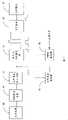
图1所示为现有的光源驱动装置,用于驱动光源模块14,其包括交流电源10、交流/直流转换器11与逆变器12。其中,交流/直流转换器11包括功率因数校正电路110、直流/交流转换电路111与变压器112。逆变器12包括电源转换电路120与逆变电路121。FIG. 1 shows a conventional light source driving device for driving a
其中,交流电源10输出交流信号,并将交流信号通过功率因数校正电路110升压转换为直流信号输出至直流/交流转换电路111。直流/交流转换电路111将直流信号转换为方波信号,并通过变压器112及其外围整流电路降压且整流后输出另一直流信号。逆变器12将接收到的直流信号转换为弦波信号,并提供给光源模块14。Wherein, the
现有的光源驱动装置中,交流输入信号需要经过直流-方波-直流-方波的转换,进而才能得到所需的弦波信号,使得转换效率明显降低,大约为70%。显然,现有光源驱动装置不仅具有较低的电源转换效率,而且还占据较大的空间,成本较高。In the existing light source driving device, the AC input signal needs to be converted by DC-square wave-DC-square wave, and then the required sine wave signal can be obtained, so that the conversion efficiency is significantly reduced, which is about 70%. Apparently, the existing light source driving device not only has low power conversion efficiency, but also occupies a larger space and costs more.
发明内容Contents of the invention
有鉴于此,需提供一种光源驱动装置,其具有较高的转换效率。In view of this, it is necessary to provide a light source driving device with higher conversion efficiency.
一种光源驱动装置,用于驱动包括多个负载的光源模块,其包括功率因数校正电路、直流/交流转换电路、隔离变压器、逆变电路以及PWM控制器。其中,功率因数校正电路用于将接收到的交流信号转换为直流信号。直流/交流转换电路与功率因数校正电路相连,用于将所述直流信号转换为另一交流信号。隔离变压器包括初级绕组与至少一个次级绕组,其中,初级绕组与直流/交流转换电路相连,用于隔离接收到的交流信号与光源模块。逆变电路与隔离变压器的次级绕组相连,用于将隔离变压器输出的交流信号转换为可驱动光源模块的交流信号。PWM控制器与直流/交流转换电路相连,用于控制直流/交流转换电路输出。A light source driving device is used to drive a light source module including multiple loads, which includes a power factor correction circuit, a DC/AC conversion circuit, an isolation transformer, an inverter circuit and a PWM controller. Wherein, the power factor correction circuit is used to convert the received AC signal into a DC signal. The DC/AC conversion circuit is connected with the power factor correction circuit for converting the DC signal into another AC signal. The isolation transformer includes a primary winding and at least one secondary winding, wherein the primary winding is connected to a DC/AC conversion circuit for isolating the received AC signal from the light source module. The inverter circuit is connected with the secondary winding of the isolation transformer, and is used for converting the AC signal output by the isolation transformer into an AC signal capable of driving the light source module. The PWM controller is connected with the DC/AC conversion circuit for controlling the output of the DC/AC conversion circuit.
一种光源驱动装置,用于驱动包括多个负载的光源模块,其包括功率因数校正电路、直流/交流转换电路、隔离变压器以及逆变电路。其中,功率因数校正电路用于将接收到的交流信号转换为直流信号。直流/交流转换电路与功率因数校正电路相连,用于将直流信号转换为另一交流信号。隔离变压器包括初级绕组与至少一个次级绕组,其中,初级绕组与直流/交流转换电路相连,用于隔离接收到的交流信号与光源模块。逆变电路与隔离变压器的次级绕组相连,用于将隔离变压器输出的交流信号转换为可驱动光源模块的交流信号,逆变电路包括多个变压器。每一变压器包括至少一个初级绕组以及至少一次级绕组。其中,变压器初级绕组的高压端均与隔离变压器次级绕组的高压端相连;变压器初级绕组的低压端均与隔离变压器次级绕组的低压端相连;变压器次级绕组的高压端分别连接负载。A light source driving device is used to drive a light source module including multiple loads, which includes a power factor correction circuit, a DC/AC conversion circuit, an isolation transformer and an inverter circuit. Wherein, the power factor correction circuit is used to convert the received AC signal into a DC signal. The DC/AC conversion circuit is connected with the power factor correction circuit for converting the DC signal into another AC signal. The isolation transformer includes a primary winding and at least one secondary winding, wherein the primary winding is connected to a DC/AC conversion circuit for isolating the received AC signal from the light source module. The inverter circuit is connected with the secondary winding of the isolation transformer, and is used to convert the AC signal output by the isolation transformer into an AC signal capable of driving the light source module. The inverter circuit includes a plurality of transformers. Each transformer includes at least one primary winding and at least one secondary winding. Wherein, the high voltage end of the primary winding of the transformer is connected with the high voltage end of the secondary winding of the isolation transformer; the low voltage end of the primary winding of the transformer is connected with the low voltage end of the secondary winding of the isolation transformer; the high voltage end of the secondary winding of the transformer is respectively connected with the load.
本发明的光源驱动装置直接将隔离变压器输出的交流信号输出至逆变电路,提高转换效率。The light source driving device of the present invention directly outputs the AC signal output by the isolation transformer to the inverter circuit, thereby improving conversion efficiency.
附图说明Description of drawings
图1为现有光源驱动装置的模块图。FIG. 1 is a block diagram of a conventional light source driving device.
图2为本发明一实施方式的光源驱动装置的模块图。FIG. 2 is a block diagram of a light source driving device according to an embodiment of the present invention.
图3为本发明图2的第一实施方式的具体电路图。FIG. 3 is a specific circuit diagram of the first embodiment of FIG. 2 of the present invention.
图4为本发明图2的第二实施方式的具体电路图。FIG. 4 is a specific circuit diagram of the second embodiment of FIG. 2 of the present invention.
图5为本发明图2的第三实施方式的具体电路图。FIG. 5 is a specific circuit diagram of the third embodiment of FIG. 2 of the present invention.
具体实施方式Detailed ways
图2所示为本发明一实施方式中光源驱动装置的模块图。该光源驱动装置用于驱动光源模块47,其包括交流电源40、电磁干扰(Electro-Magnetic Interference,EMI)滤波电路41、功率因数校正电路42、功率因数控制器43、直流/交流转换电路44、隔离变压器T1、逆变电路45以及脉波宽度调变(Pulse-Width Modulation,PWM)控制器46。本实施方式中,光源模块47包括多个负载,例如:放电灯(Discharge Lamp)。FIG. 2 is a block diagram of a light source driving device in an embodiment of the present invention. The light source driving device is used to drive the
同样,交流电源40提供交流信号,并通过EMI滤波电路41传送至功率因数校正电路42。EMI滤波电路41连接于交流电源40与功率因数校正电路42之间,用于滤除交流电源40输出的交流信号中的EMI信号。本实施方式中,功率因数校正电路42为升压型电路,其用于将交流信号转换为直流信号并升压。在本实施例中,升压后的直流信号大约为400V。Likewise, the
本实施方式中,功率因数控制器42用于将功率因数校正电路的输出反馈至功率因数校正电路,以稳定功率因数校正电路的直流输出。In this embodiment, the
直流/交流转换电路44与功率因数校正电路42相连,用于将功率因数校正电路42输出的直流信号转换为交流信号。本实施方式中,直流/交流转换电路44输出的交流信号为方波信号,且直流/交流转换电路44可以为全桥式架构(Full-Bridge)、半桥式架构(Half-Bridge)、推挽式架构(Push-Pull)或是自激式(Royer)架构。The DC/
隔离变压器T1具有初级绕组与次级绕组,其中,初级绕组与直流/交流转换电路44相连,其次级绕组与逆变电路45相连。本发明其他实施方式中,隔离变压器T1也可具有多个次级绕组。通常,根据安规可知,交流电源40输出的电压属于危险电压,为了使得光源模块47及驱动其的逆变电路45处于安全状态,则使用隔离变压器T1将危险的交流电源40与光源模块47及驱动其的逆变电路45隔离开来。本实施方式中,隔离变压器T1同时还具有降压的功能。The isolation transformer T1 has a primary winding and a secondary winding, wherein the primary winding is connected to the DC/
逆变电路45用于将隔离变压器T1输出的交流信号转换为另一交流信号,并输出给光源模块47用于驱动其点亮。本实施方式中,逆变电路45输出的交流信号为弦波信号。The
PWM控制器46与直流/交流转换电路44相连,用于根据接收到的反馈信号控制直流/交流转换电路44的输出。本实施方式中,反馈信号可以是电流反馈信号,即由电流反馈电路(图中未显示)将流经光源模块47的电流反馈至PWM控制器46;抑或是由感测电路(图中未显示)将感测到的光源模块47的电压、温度等反馈信号反馈至PWM控制器46。因此,PWM控制器46可根据所述反馈信号检测流经光源模块47的电流、加载在光源模块47上的电压、光源模块47的温度等,从而控制直流/交流转换电路44的输出。The
图3所示为图2的具体电路图。其中,逆变电路45包括多个变压器T4n(n=1,2,3,...,n)及多个电容C4n(n=1,2,3,...,n),光源模块47包括多个负载L4n(n=1,2,3,...,n)。其中,每一变压器T4n(n=1,2,3,...,n)均包括初级绕组与次级绕组。本实施方式中,变压器T4n(n=1,2,3,...,n)初级绕组的高端均与隔离变压器的次级绕组的高压端相连,变压器T4n(n=1,2,3,...,n)初级绕组的低压端均与隔离变压器次级绕组的低压端相连。变压器T4n(n=1,2,3,...,n)次级绕组的高压端对应连接负载的一端,变压器T4n(n=1,2,3,...,n)次级绕组的低压端接地,且负载L4n(n=1,2,3,...,n)的另一端接地。电容C4n(n=1,2,3,...,n)对应跨接于变压器T4n(n=1,2,3,...,n)次级绕组的高压端与低压端之间,与变压器T4n(n=1,2,3,...,n)次级绕组的漏电感形成谐振电路,将隔离后的直流信号转换为可驱动光源模块47的交流信号。本发明其它实施方式中,由于负载L4n(n=1,2,3,...,n)中存在有寄生电容,其可以代替电容C4n(n=1,2,3,...,n)与变压器T1次级绕组的漏感形成谐振电路,该种情况下,电容C4n(n=1,2,3,...,n)可以省略。且,C4n(n=1,2,3,...,n)与变压器T1次级绕组也可以采用其它方式连接,其不局限于本实施方式的连接方式。同样,本发明其他实施方式中,变压器T4n(n=1,2,3,...,n)也可具有多个次级绕组。Figure 3 shows the specific circuit diagram of Figure 2 . Wherein, the
图4为本发明图2的另一具体电路图。其中,逆变电路55包括多个变压器T5n(n=1,2,3,...,n)以及多个电容C5k(k=1,2,3,...,2n),光源模块57包括多个负载L5k(k=1,2,3,...,2n)。其中,每一变压器T5n(n=1,2,3,...,n)均包括初级绕组、第一次级绕组以及第二次级绕组。变压器T5n(n=1,2,3,...,n)初级绕组的高压端均与隔离变压器T1次级绕组的高压端相连,变压器T5n(n=1,2,3,...,n)次级绕组的低压端均与隔离变压器T1次级绕组的低压端相连。于每一变压器T5n(n=1,2,3,...,n)中,第一与第二次级绕组的高压端分别对应连接负载的一端,其低压端均接地。且,所述负载的另一端亦接地。电容C5k(k=1,2,3,...,2n)对应跨接于变压器T5n(n=1,2,3,...,n)的第一次级绕组高压端与低压端之间,以及变压器T5n(n=1,2,3,...,n)第二次级绕组的高压端与低压端之间,与变压器T5n(n=1,2,3,...,n)第一、第二次级绕组的漏电感形成谐振电路,将隔离后的直流信号转换为可驱动光源模块57的交流信号。同样,本发明其他实施方式中,变压器T4n(n=1,2,3,...,n)也可具有多个次级绕组。FIG. 4 is another specific circuit diagram of FIG. 2 of the present invention. Wherein, the
图5为本发明图2的又一具体电路图,其与图4所示的电路结构基本相同,区别在于:图5所示的光源模块67包括多个负载L6m(m=1,2,3,...,4n),且每一变压器T6(n)(n=1,2,3,...,n)的第一次级绕组与第二次级绕组的高压端与低压端分别对应连接负载。Fig. 5 is another specific circuit diagram of Fig. 2 of the present invention, which is basically the same as the circuit structure shown in Fig. 4, the difference is that the
由此可见,本发明的光源驱动装置直接将隔离变压器输出的交流信号输出给逆变电路,其省略现有的整流电路与电源转换电路,使得整体转换效率可达85%,而且同时减小了光源驱动装置的体积、降低成本。It can be seen that the light source driving device of the present invention directly outputs the AC signal output by the isolation transformer to the inverter circuit, which omits the existing rectification circuit and power conversion circuit, so that the overall conversion efficiency can reach 85%, and at the same time reduces the The volume of the light source driving device is reduced, and the cost is reduced.
Claims (11)
Translated fromChinesePriority Applications (2)
| Application Number | Priority Date | Filing Date | Title |
|---|---|---|---|
| CNA2006100630336ACN101163361A (en) | 2006-10-11 | 2006-10-11 | Light source driving device |
| US11/616,884US7492107B2 (en) | 2006-10-11 | 2006-12-28 | Device for driving light source module |
Applications Claiming Priority (1)
| Application Number | Priority Date | Filing Date | Title |
|---|---|---|---|
| CNA2006100630336ACN101163361A (en) | 2006-10-11 | 2006-10-11 | Light source driving device |
Publications (1)
| Publication Number | Publication Date |
|---|---|
| CN101163361Atrue CN101163361A (en) | 2008-04-16 |
Family
ID=39298157
Family Applications (1)
| Application Number | Title | Priority Date | Filing Date |
|---|---|---|---|
| CNA2006100630336APendingCN101163361A (en) | 2006-10-11 | 2006-10-11 | Light source driving device |
Country Status (2)
| Country | Link |
|---|---|
| US (1) | US7492107B2 (en) |
| CN (1) | CN101163361A (en) |
Cited By (5)
| Publication number | Priority date | Publication date | Assignee | Title |
|---|---|---|---|---|
| CN102695324A (en)* | 2011-03-25 | 2012-09-26 | 国琏电子(上海)有限公司 | Light source module power supply system |
| CN101568219B (en)* | 2008-04-23 | 2013-01-09 | 鸿富锦精密工业(深圳)有限公司 | Light source driving device |
| CN103069210A (en)* | 2010-06-10 | 2013-04-24 | 生态流明有限责任公司 | Light emitting diode (LED) lighting systems and methods |
| CN111879987A (en)* | 2020-07-16 | 2020-11-03 | 北京瑞赛长城航空测控技术有限公司 | High-voltage-resistant isolated contact detection circuit |
| CN116191906A (en)* | 2023-03-07 | 2023-05-30 | 东莞市晟鼎精密仪器有限公司 | Intelligent monitoring system and method for double-pulse plasma power supply |
Families Citing this family (10)
| Publication number | Priority date | Publication date | Assignee | Title |
|---|---|---|---|---|
| US20080165114A1 (en)* | 2007-01-10 | 2008-07-10 | Logah Technology Corp. | Lcd backlight driving device with an isolating transformer |
| US8378962B2 (en)* | 2007-01-10 | 2013-02-19 | Logah Technology Corp. | LCD backlight driving device with an isolating transformer |
| US20080265790A1 (en)* | 2007-04-27 | 2008-10-30 | Cheng-Chia Hsu | Coupled lamp driving device |
| US8084954B2 (en)* | 2008-04-18 | 2011-12-27 | Samsung Electro-Mechanics Co., Ltd. | Lamp driving circuit |
| US20100052568A1 (en)* | 2008-08-27 | 2010-03-04 | Texas Instruments Incorporated | Light emitting diode array driver |
| US8242704B2 (en)* | 2008-09-09 | 2012-08-14 | Point Somee Limited Liability Company | Apparatus, method and system for providing power to solid state lighting |
| CN201789412U (en)* | 2010-08-25 | 2011-04-06 | 国琏电子(上海)有限公司 | Power supply system |
| US20130082611A1 (en) | 2011-08-29 | 2013-04-04 | Texas Instruments Incorporated | Feed forward controlled voltage to current source for led driver |
| US9509433B2 (en)* | 2013-05-14 | 2016-11-29 | Applied Optoelectronics, Inc. | Aligning and directly optically coupling photodetectors to optical demultiplexer outputs in a multichannel receiver optical subassembly |
| US9847434B2 (en) | 2015-03-23 | 2017-12-19 | Applied Optoelectronics, Inc. | Multichannel receiver optical subassembly with improved sensitivity |
Family Cites Families (11)
| Publication number | Priority date | Publication date | Assignee | Title |
|---|---|---|---|---|
| JPH11500861A (en) | 1995-12-08 | 1999-01-19 | フィリップス、エレクトロニクス、ネムローゼ、フェンノートシャップ | Ballast system |
| US6353803B1 (en) | 1996-01-18 | 2002-03-05 | Yeda Research And Development Co., Ltd. At The Welzmann Institute Of Science | Apparatus for monitoring a system in which a fluid flows |
| US7155043B2 (en) | 2001-11-21 | 2006-12-26 | Confirma, Incorporated | User interface having analysis status indicators |
| US7260249B2 (en) | 2002-09-27 | 2007-08-21 | Confirma Incorporated | Rules-based approach for processing medical images |
| US6864642B2 (en)* | 2002-10-07 | 2005-03-08 | Bruce Industries, Inc. | Electronic ballast with DC output flyback converter |
| US6936975B2 (en)* | 2003-04-15 | 2005-08-30 | 02Micro International Limited | Power supply for an LCD panel |
| WO2005004553A1 (en)* | 2003-07-04 | 2005-01-13 | Koninklijke Philips Electronics N.V. | System for operating a plurality of negative dynamical impedance loads |
| JP2005129004A (en)* | 2003-10-03 | 2005-05-19 | Sharp Corp | Drive system and AC converter |
| US7443113B2 (en)* | 2003-12-02 | 2008-10-28 | Universal Lighting Technologies, Inc. | Software controlled electronic dimming ballast |
| TWI236863B (en)* | 2004-01-28 | 2005-07-21 | Asia Optical Co Inc | Ballast device having active ballasting circuit and method thereof |
| US7541746B2 (en)* | 2005-09-15 | 2009-06-02 | Infocus Corporation | Lamp driver circuit with power factor correction circuit coupled to direct-current to direct-current power converter |
- 2006
- 2006-10-11CNCNA2006100630336Apatent/CN101163361A/enactivePending
- 2006-12-28USUS11/616,884patent/US7492107B2/ennot_activeExpired - Fee Related
Cited By (7)
| Publication number | Priority date | Publication date | Assignee | Title |
|---|---|---|---|---|
| CN101568219B (en)* | 2008-04-23 | 2013-01-09 | 鸿富锦精密工业(深圳)有限公司 | Light source driving device |
| CN103069210A (en)* | 2010-06-10 | 2013-04-24 | 生态流明有限责任公司 | Light emitting diode (LED) lighting systems and methods |
| CN102695324A (en)* | 2011-03-25 | 2012-09-26 | 国琏电子(上海)有限公司 | Light source module power supply system |
| CN111879987A (en)* | 2020-07-16 | 2020-11-03 | 北京瑞赛长城航空测控技术有限公司 | High-voltage-resistant isolated contact detection circuit |
| CN111879987B (en)* | 2020-07-16 | 2023-10-20 | 北京瑞赛长城航空测控技术有限公司 | High-voltage-resistant isolated contact detection circuit |
| CN116191906A (en)* | 2023-03-07 | 2023-05-30 | 东莞市晟鼎精密仪器有限公司 | Intelligent monitoring system and method for double-pulse plasma power supply |
| CN116191906B (en)* | 2023-03-07 | 2023-11-07 | 东莞市晟鼎精密仪器有限公司 | Intelligent monitoring system and method for double-pulse plasma power supply |
Also Published As
| Publication number | Publication date |
|---|---|
| US7492107B2 (en) | 2009-02-17 |
| US20080088255A1 (en) | 2008-04-17 |
Similar Documents
| Publication | Publication Date | Title |
|---|---|---|
| CN101163361A (en) | Light source driving device | |
| US8179053B2 (en) | Power supply for an LCD display | |
| US6703796B2 (en) | Power supply and inverter used therefor | |
| US7443108B2 (en) | Apparatus for driving a plurality of lamps | |
| TW200945952A (en) | Light source driving device | |
| US7550929B2 (en) | Power system and method for driving plural lamps | |
| JP2006351544A (en) | Power supply device | |
| US8120262B2 (en) | Driving circuit for multi-lamps | |
| US8143804B2 (en) | Light source driving device | |
| JP4697748B2 (en) | Backlight drive system for liquid crystal display | |
| EP1978623A2 (en) | Fluorescent lamp power driver | |
| US20080089099A1 (en) | Half-bridge CCFL driving apparatus | |
| CN101409972B (en) | For multiple cold cathode fluorescence lamps and/or the drive system of external-electrode fluorescent lamp and method | |
| CN101568219B (en) | Light source driving device | |
| US7518317B2 (en) | Backlight driving and control circuit with an isolated power factor correction structure | |
| US7579789B2 (en) | Device for driving light sources | |
| CN101001495B (en) | Semi-bridge type cold cathode lamp tube driving device | |
| CN101118323A (en) | Backlight driving and control circuit with isolated power factor correction framework | |
| TW200820830A (en) | Light source module driving device | |
| US7256553B1 (en) | Lamp driving system controlled by electrical isolation | |
| US20070200507A1 (en) | Device for driving light source module | |
| CN101179894A (en) | Current converter and driving device of backlight module | |
| TWI401996B (en) | Light source driving device | |
| JP2007265897A (en) | Inverter circuit for discharge tube | |
| CN201256476Y (en) | Multi-lamp tube driving device |
Legal Events
| Date | Code | Title | Description |
|---|---|---|---|
| C06 | Publication | ||
| PB01 | Publication | ||
| C10 | Entry into substantive examination | ||
| SE01 | Entry into force of request for substantive examination | ||
| C02 | Deemed withdrawal of patent application after publication (patent law 2001) | ||
| WD01 | Invention patent application deemed withdrawn after publication | Open date:20080416 |