CN101161426A - Flexible connecting line structure between integrated circuit board in the finger of robot delicacy hand - Google Patents
Flexible connecting line structure between integrated circuit board in the finger of robot delicacy handDownload PDFInfo
- Publication number
- CN101161426A CN101161426ACNA2007101444669ACN200710144466ACN101161426ACN 101161426 ACN101161426 ACN 101161426ACN A2007101444669 ACNA2007101444669 ACN A2007101444669ACN 200710144466 ACN200710144466 ACN 200710144466ACN 101161426 ACN101161426 ACN 101161426A
- Authority
- CN
- China
- Prior art keywords
- flexible
- rigid
- circuit board
- joint
- rigid plate
- Prior art date
- Legal status (The legal status is an assumption and is not a legal conclusion. Google has not performed a legal analysis and makes no representation as to the accuracy of the status listed.)
- Granted
Links
Images


Landscapes
- Manipulator (AREA)
Abstract
Description
Translated fromChinese技术领域technical field
本发明涉及一种机器人手指内集成电路板之间的连线结构。The invention relates to a wiring structure between integrated circuit boards in a robot finger.
背景技术Background technique
机器人灵巧手作为机器人系统的末端操作器,对机器人系统的作业能力、特别是灵巧操作能力具有重要的影响。20世纪80年代后,一些国家进行了机器人灵巧手的研究,也相继诞生了一些有代表性的灵巧手,比如Stanford/JPL手、Utan/M.I.T手、DLR手、NASA手等等,在灵巧手的概念、驱动、传感器等方面对后续甚至今天灵巧手的研究产生了很大的影响。电气系统作为机器人灵巧手的重要组成部分之一,主要实现电机驱动、传感器信息的采集等功能,其结构组成、电气连接等对灵巧手系统的机电一体化构成、系统的稳定性和可靠性等有重要的影响。内置式和外置式是当前灵巧手设计中的两个主要的研究方向,内置式是将驱动、传动、传感及电气等集成在手指或手掌中,对于臂手系统的集成、可靠性、可维护性等有更合理的优势,在空间布置、连接及走线等方面对电气系统有更加严格的要求。内置式的灵巧手要求电路板更加小巧,通过机械、电气的一体化设计,能够集成在手指内部。As the end effector of the robot system, the robotic dexterous hand has an important impact on the operation ability of the robot system, especially the dexterous operation ability. After the 1980s, some countries carried out research on robotic dexterous hands, and some representative dexterous hands were born one after another, such as Stanford/JPL hand, Utan/M.I.T hand, DLR hand, NASA hand, etc. The concept, drive, sensor and other aspects of the dexterous hand have had a great impact on the follow-up and even today's research on dexterous hands. As one of the important components of the robot dexterous hand, the electrical system mainly realizes functions such as motor drive and sensor information collection. have an important impact. Built-in and external are the two main research directions in the current dexterous hand design. The built-in is the integration of drive, transmission, sensing and electricity in the finger or palm. There are more reasonable advantages in maintainability, etc., and there are stricter requirements on the electrical system in terms of space layout, connection and wiring. The built-in dexterous hand requires a smaller circuit board, which can be integrated inside the finger through an integrated mechanical and electrical design.
现有的机器人灵巧手手指内的电路板及其连线布置存在电路板布局不合理、连线复杂、走线方式不合理、可靠性差的问题以致难于实现机电集成。而且手指连线对转动关节的适应性差,甚至还影响关节的运动,同时还干扰信号的传播;从而使手指连线的故障发生率高,极大地降低了机器人灵巧手电气系统的工作可靠性。The circuit board and its connection arrangement in the existing robot dexterous hand fingers have the problems of unreasonable circuit board layout, complicated connection, unreasonable wiring method and poor reliability, so that it is difficult to realize electromechanical integration. Moreover, the adaptability of the finger connection to the rotating joint is poor, and even affects the movement of the joint, and at the same time interferes with the propagation of the signal; thus the failure rate of the finger connection is high, which greatly reduces the working reliability of the robot dexterous hand electrical system.
发明内容Contents of the invention
本发明为了解决现有的机器人灵巧手手指内的电路板及其连线布置存在电路板布局不合理、连线复杂、走线方式不合理、可靠性差的问题以致难于实现机电集成、手指连线对转动关节的适应性差、影响关节的运动的问题,进而提供了一种机器人灵巧手手指内集成电路板之间的柔性连线结构。The present invention solves the problems of unreasonable circuit board layout, complex wiring, unreasonable routing and poor reliability in the circuit board and its connection arrangement in the existing robot dexterous hand fingers, so that it is difficult to realize electromechanical integration and finger connection. The problem of poor adaptability to rotating joints and affecting the movement of joints provides a flexible connection structure between integrated circuit boards in the fingers of a robot dexterous hand.
本发明的技术方案是:机器人灵巧手手指内集成电路板之间的柔性连线结构,它包括手指柔性电路板、手指刚性电路板、基关节柔性连接线束、基关节柔性电路板和基关节刚性电路板;所述的手指柔性电路板1由第一刚性板、第二刚性板、第三刚性板、第一柔性排线、第二柔性排线、第三柔性排线、第四柔性排线组成,第一刚性板固定在末端指节上,第二刚性板和第三刚性板分别固定在第二指节上,第一柔性排线的一端与指尖力矩传感器连接,第一柔性排线的另一端与第一刚性板连接,第二柔性排线的一端与第一刚性板连接,第二柔性排线的另一端与第二刚性板连接,第三柔性排线的一端与第二刚性板连接,第三柔性排线的另一端与第三刚性板连接,第四柔性排线的一端与第二刚性板连接;第四柔性排线的另一端与手指刚性电路板连接,手指刚性电路板固定在第一指节的指背位置;基关节柔性连接线束的一端与手指刚性电路板连接,基关节柔性连接线束的另一端与基关节柔性电路板中的第四刚性板连接;基关节柔性电路板由第四刚性板和第五柔性排线组成,第四刚性板固定在不运动的基指节的背部;基关节刚性电路板固定在不运动的基指节的底部;第五柔性排线的一端与第四刚性板连接,第五柔性排线的另一端与基关节刚性电路板连接。The technical scheme of the present invention is: the flexible wiring structure between the integrated circuit boards in the fingers of the robot dexterous hand, which includes a flexible circuit board for fingers, a rigid circuit board for fingers, a flexible connection harness for base joints, a flexible circuit board for base joints, and a rigid circuit board for base joints. Circuit board; the finger
本发明具有以下有益效果:本发明实现了电路板间的柔性走线连接,有效地降低了手指连线的复杂性、提高了电气系统的可靠性。具有电路板布局合理、连线简单、走线方式合理、不影响关节的运动、减小或避免信号受到干扰、手指连线对转动关节的适应性好的优点。The invention has the following beneficial effects: the invention realizes the flexible wiring connection between the circuit boards, effectively reduces the complexity of the finger connection, and improves the reliability of the electrical system. The utility model has the advantages of reasonable circuit board layout, simple wiring, reasonable wiring method, no influence on joint movement, reduced or avoided signal interference, and good adaptability of finger wiring to rotating joints.
附图说明Description of drawings
图1是本发明的电路板连接的线路构造示意图,图2是电路板及电路板间的柔性走线在手指上布置的立体图,图3是末端关节的电路板间的柔性走线布置的立体图(末端指节6伸直状态),图4是末端关节的电路板间的柔性走线布置的立体图(末端指节6弯曲状态),图5是中间关节的电路板间的柔性走线布置的立体图(第二指节7伸直状态),图6是中间关节的电路板间的柔性走线布置的立体图(第二指节7弯曲状态),图7是基关节的中心轴孔走线布置的立体图,图8是图7的A-A剖视图,图9是图8的B-B剖视图,图10是中心轴孔走线的原理图,图11是具体实施方式五所述的柔性线的弯曲在空间内的状态图,图12是柔性线的一端D固定而另一端E移动时的状态图,图13是当柔性线的移动端E向反方向移动进而回到初始点的过程中的状态图。Fig. 1 is a schematic diagram of the circuit structure of the circuit board connection of the present invention, Fig. 2 is a perspective view of the layout of the circuit board and the flexible wiring between the circuit boards on the finger, Fig. 3 is a perspective view of the flexible wiring arrangement between the circuit boards of the terminal joint (
具体实施方式Detailed ways
具体实施方式一:如图1~9所示,本实施方式的机器人灵巧手手指内集成电路板之间的柔性连线结构由手指柔性电路板1、手指刚性电路板2、基关节柔性连接线束3、基关节柔性电路板4和基关节刚性电路板5组成;所述的手指柔性电路板1由第一刚性板1-2、第二刚性板1-4、第三刚性板1-6、第一柔性排线1-1、第二柔性排线1-3、第三柔性排线1-5、第四柔性排线1-7组成,第一刚性板1-2固定在末端指节6上,第二刚性板1-4和第三刚性板1-6分别固定在第二指节7上且相互垂直,第一柔性排线1-1的一端与指尖力矩传感器20连接,第一柔性排线1-1的另一端与第一刚性板1-2连接,第二柔性排线1-3的一端与第一刚性板1-2连接,第二柔性排线1-3的另一端与第二刚性板1-4连接,第三柔性排线1-5的一端与第二刚性板1-4连接,第三柔性排线1-5的另一端与第三刚性板1-6连接,第四柔性排线1-7的一端与第二刚性板1-4连接;第四柔性排线1-7的另一端与手指刚性电路板2连接,手指刚性电路板2固定在第一指节8的指背位置;基关节柔性连接线束3的一端与手指刚性电路板2连接,基关节柔性连接线束3的另一端与基关节柔性电路板4中的第四刚性板4-1连接;基关节柔性电路板4由第四刚性板4-1和第五柔性排线4-2组成,第四刚性板4-1固定在不运动的基指节9的背部;基关节刚性电路板5固定在不运动的基指节9的底部;第五柔性排线4-2的一端与第四刚性板4-1连接,第五柔性排线4-2的另一端与基关节刚性电路板5连接。手指刚性电路板2还与基关节力矩传感器、驱动电机连接;基关节柔性电路板4与基关节绝对位置传感器通过插座连接;基关节刚性电路板5驱动基关节的两个直流电机并通过弹簧触针连接方式实现手指电气与手掌电气的连接。当中间关节11和末端关节10转动时,通过第二柔性排线1-3和第四柔性排线1-7走线路径发生变化,使柔性线能够适应由于关节转动对线长变化的要求。Embodiment 1: As shown in Figures 1 to 9, the flexible connection structure between the integrated circuit boards in the fingers of the robotic dexterous hand in this embodiment consists of a finger
具体实施方式二:如图3和图4所示,本实施方式还包括导线销钉13,所述的导线销钉13设置在末端指节6上,所述的第二柔性排线1-3缠绕在所述的导线销钉13上。当手指末端关节伸直时,第一刚性板1-2和第二刚性板1-4之间的距离最小,过长的第二柔性排线1-3在导线销钉13和其自身刚度的作用下,叠绕在第二指节7的内侧;当末端关节10逐渐弯曲时,第一刚性板1-2和第二刚性板1-4之间的距离增大,拉动第二柔性排线1-3,同时导线销钉13绕末端关节10顺时针旋转,第二柔性排线1-3能够满足上述两刚性板距离增大的要求。导线销钉13的作用,主要是在手指伸直状态下,将第二柔性排线1-3拉起,避免与第四柔性排线1-7相互推挤、干扰。其它组成和连接关系与具体实施方式一相同。Specific embodiment two: as shown in Figure 3 and Figure 4, this embodiment also includes a wire pin 13, the wire pin 13 is arranged on the
具体实施方式三:如图5和图6所示,本实施方式所述的第四柔性排线1-7“跨越”中间关节11、第二刚性板1-4和手指刚性电路板2。当11中间关节伸直时,第二刚性板1-4和手指刚性电路板2之间的距离最小,过长的第四柔性排线1-7在自身刚度的作用下,绕在中间关节11的外边缘、第二指节7的内侧;当手指第二关节7逐渐弯曲时,上述两个刚性板之间的距离增大,拉动第四柔性排线1-7,第四柔性排线1-7能够满足刚性板距离增大的要求。其它组成和连接关系与具体实施方式一相同。Embodiment 3: As shown in FIG. 5 and FIG. 6 , the fourth flexible cable 1-7 in this embodiment "straddles" the
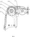
具体实施方式四:如图7~10所示,本实施方式所述的基关节柔性连接线束3穿过连接件14上的通孔14-1和基关节转动轴12上的径向孔12-1穿入基关节转动轴12内,所述的基关节柔性连接线束3在径向孔12-1(基关节转动轴12的中间位置,俯仰方向和侧摆方向的交叉点)处分成两束,即第一连接线束3-1和第二连接线束3-2,所述的第一连接线束3-1沿基关节转动轴的轴向内孔12-2从基关节转动轴12的一端穿出,所述的第二连接线束3-2沿基关节转动轴的轴向内孔12-2从基关节转动轴12的另一端穿出,所述的第一连接线束3-1沿基指节右侧壁9-1连接到第四刚性板4-1上,所述的第二连接线束3-2沿基指节左侧壁9-2连接到第四刚性板4-1上。这样走线,当基关节沿俯仰、侧摆方向转动时,由于基关节柔性连接线束3通过转动轴的中心,关节转动而基关节柔性连接线束3的长度不变化,从而避免了由于关节转动对线长度变化的要求。其原理相当于图10所示的结构,线穿过球心,当柔性线端C沿着球面S运动时,柔性线端C到球心0的距离L不变。极大增强了手指内部连线对转动关节的适应性。其它组成和连接关系与具体实施方式一相同。Embodiment 4: As shown in Figures 7 to 10, the base joint
具体实施方式五:如图11~13所示,本实施方式所述的第一柔性排线1-1、第二柔性排线1-3、第三柔性排线1-5、第四柔性排线1-7、基关节柔性连接线束3、第五柔性排线4-2沿轴向方向均具有一定的刚度、沿径向方向均能完成一定曲率的弯曲。这样才能满足“跨越”关节的板间连接要求,根据关节的弯曲调整柔性线的弯曲位置、走线路径、走线长度,从而适应由于关节弯曲所造成的连线长度的变化。柔性线弯曲在有一定距离的两个平面空间内,线的一端D固定,当另一端E移动时,拉动柔性线,弯曲点F随之移动;当移动端E向反方向移动、回到初始点的过程中,由于柔性线自身的刚度,能够推动弯曲点F随之移动、回到初始位置。其它组成和连接关系与具体实施方式一相同。Embodiment 5: As shown in Figures 11-13, the first flexible cable 1-1, the second flexible cable 1-3, the third flexible cable 1-5, and the fourth flexible cable described in this embodiment The wires 1-7, the base joint flexible connecting
Claims (4)
Priority Applications (1)
| Application Number | Priority Date | Filing Date | Title |
|---|---|---|---|
| CNB2007101444669ACN100522507C (en) | 2007-10-19 | 2007-10-19 | Flexible connecting line structure between integrated circuit board in the finger of robot delicacy hand |
Applications Claiming Priority (1)
| Application Number | Priority Date | Filing Date | Title |
|---|---|---|---|
| CNB2007101444669ACN100522507C (en) | 2007-10-19 | 2007-10-19 | Flexible connecting line structure between integrated circuit board in the finger of robot delicacy hand |
Publications (2)
| Publication Number | Publication Date |
|---|---|
| CN101161426Atrue CN101161426A (en) | 2008-04-16 |
| CN100522507C CN100522507C (en) | 2009-08-05 |
Family
ID=39296450
Family Applications (1)
| Application Number | Title | Priority Date | Filing Date |
|---|---|---|---|
| CNB2007101444669AExpired - Fee RelatedCN100522507C (en) | 2007-10-19 | 2007-10-19 | Flexible connecting line structure between integrated circuit board in the finger of robot delicacy hand |
Country Status (1)
| Country | Link |
|---|---|
| CN (1) | CN100522507C (en) |
Cited By (29)
| Publication number | Priority date | Publication date | Assignee | Title |
|---|---|---|---|---|
| CN102781632A (en)* | 2010-03-02 | 2012-11-14 | Abb研究有限公司 | robot wrist |
| CN107866820A (en)* | 2017-12-26 | 2018-04-03 | 哈尔滨思哲睿智能医疗设备有限公司 | A kind of bar linkage structure mechanical arm rotates string-passing structure |
| CN109069138A (en)* | 2016-08-31 | 2018-12-21 | 奥瑞斯健康公司 | The surgical instrument of length conservation |
| CN111331576A (en)* | 2018-12-18 | 2020-06-26 | 北京华航无线电测量研究所 | Wiring method of flexible printed board suitable for small servo rotary platform |
| US10903725B2 (en) | 2016-04-29 | 2021-01-26 | Auris Health, Inc. | Compact height torque sensing articulation axis assembly |
| US11026758B2 (en) | 2017-06-28 | 2021-06-08 | Auris Health, Inc. | Medical robotics systems implementing axis constraints during actuation of one or more motorized joints |
| US11213363B2 (en) | 2013-03-14 | 2022-01-04 | Auris Health, Inc. | Catheter tension sensing |
| US11278703B2 (en) | 2014-04-21 | 2022-03-22 | Auris Health, Inc. | Devices, systems, and methods for controlling active drive systems |
| US11350998B2 (en) | 2014-07-01 | 2022-06-07 | Auris Health, Inc. | Medical instrument having translatable spool |
| US11376085B2 (en) | 2013-03-15 | 2022-07-05 | Auris Health, Inc. | Remote catheter manipulator |
| US11382650B2 (en) | 2015-10-30 | 2022-07-12 | Auris Health, Inc. | Object capture with a basket |
| US11439419B2 (en) | 2019-12-31 | 2022-09-13 | Auris Health, Inc. | Advanced basket drive mode |
| US11452844B2 (en) | 2013-03-14 | 2022-09-27 | Auris Health, Inc. | Torque-based catheter articulation |
| US11504195B2 (en) | 2013-03-15 | 2022-11-22 | Auris Health, Inc. | Active drive mechanism for simultaneous rotation and translation |
| US11510736B2 (en) | 2017-12-14 | 2022-11-29 | Auris Health, Inc. | System and method for estimating instrument location |
| US11517717B2 (en) | 2013-03-14 | 2022-12-06 | Auris Health, Inc. | Active drives for robotic catheter manipulators |
| US11534249B2 (en) | 2015-10-30 | 2022-12-27 | Auris Health, Inc. | Process for percutaneous operations |
| US11571229B2 (en) | 2015-10-30 | 2023-02-07 | Auris Health, Inc. | Basket apparatus |
| US11660153B2 (en) | 2013-03-15 | 2023-05-30 | Auris Health, Inc. | Active drive mechanism with finite range of motion |
| US11690977B2 (en) | 2014-05-15 | 2023-07-04 | Auris Health, Inc. | Anti-buckling mechanisms for catheters |
| US11737845B2 (en) | 2019-09-30 | 2023-08-29 | Auris Inc. | Medical instrument with a capstan |
| US11771521B2 (en) | 2015-09-09 | 2023-10-03 | Auris Health, Inc. | Instrument device manipulator with roll mechanism |
| US11771309B2 (en) | 2016-12-28 | 2023-10-03 | Auris Health, Inc. | Detecting endolumenal buckling of flexible instruments |
| US11779414B2 (en) | 2013-03-14 | 2023-10-10 | Auris Health, Inc. | Active drive for robotic catheter manipulators |
| US11839439B2 (en) | 2017-12-11 | 2023-12-12 | Auris Health, Inc. | Systems and methods for instrument based insertion architectures |
| US11864842B2 (en) | 2018-09-28 | 2024-01-09 | Auris Health, Inc. | Devices, systems, and methods for manually and robotically driving medical instruments |
| US11896330B2 (en) | 2019-08-15 | 2024-02-13 | Auris Health, Inc. | Robotic medical system having multiple medical instruments |
| US11950872B2 (en) | 2019-12-31 | 2024-04-09 | Auris Health, Inc. | Dynamic pulley system |
| US12364557B2 (en) | 2018-06-27 | 2025-07-22 | Auris Health, Inc. | Alignment and attachment systems for medical instruments |
- 2007
- 2007-10-19CNCNB2007101444669Apatent/CN100522507C/ennot_activeExpired - Fee Related
Cited By (39)
| Publication number | Priority date | Publication date | Assignee | Title |
|---|---|---|---|---|
| CN102781632B (en)* | 2010-03-02 | 2015-06-03 | Abb研究有限公司 | robot wrist |
| CN102781632A (en)* | 2010-03-02 | 2012-11-14 | Abb研究有限公司 | robot wrist |
| US12420063B2 (en) | 2013-03-14 | 2025-09-23 | Auris Health, Inc. | Torque-based catheter articulation |
| US11779414B2 (en) | 2013-03-14 | 2023-10-10 | Auris Health, Inc. | Active drive for robotic catheter manipulators |
| US11517717B2 (en) | 2013-03-14 | 2022-12-06 | Auris Health, Inc. | Active drives for robotic catheter manipulators |
| US11213363B2 (en) | 2013-03-14 | 2022-01-04 | Auris Health, Inc. | Catheter tension sensing |
| US11452844B2 (en) | 2013-03-14 | 2022-09-27 | Auris Health, Inc. | Torque-based catheter articulation |
| US11376085B2 (en) | 2013-03-15 | 2022-07-05 | Auris Health, Inc. | Remote catheter manipulator |
| US12114943B2 (en) | 2013-03-15 | 2024-10-15 | Auris Health, Inc. | Remote catheter manipulator |
| US11660153B2 (en) | 2013-03-15 | 2023-05-30 | Auris Health, Inc. | Active drive mechanism with finite range of motion |
| US11504195B2 (en) | 2013-03-15 | 2022-11-22 | Auris Health, Inc. | Active drive mechanism for simultaneous rotation and translation |
| US11278703B2 (en) | 2014-04-21 | 2022-03-22 | Auris Health, Inc. | Devices, systems, and methods for controlling active drive systems |
| US12343483B2 (en) | 2014-05-15 | 2025-07-01 | Auris Health, Inc. | Anti-buckling mechanisms for catheters |
| US11690977B2 (en) | 2014-05-15 | 2023-07-04 | Auris Health, Inc. | Anti-buckling mechanisms for catheters |
| US11350998B2 (en) | 2014-07-01 | 2022-06-07 | Auris Health, Inc. | Medical instrument having translatable spool |
| US11771521B2 (en) | 2015-09-09 | 2023-10-03 | Auris Health, Inc. | Instrument device manipulator with roll mechanism |
| US11571229B2 (en) | 2015-10-30 | 2023-02-07 | Auris Health, Inc. | Basket apparatus |
| US11534249B2 (en) | 2015-10-30 | 2022-12-27 | Auris Health, Inc. | Process for percutaneous operations |
| US11559360B2 (en) | 2015-10-30 | 2023-01-24 | Auris Health, Inc. | Object removal through a percutaneous suction tube |
| US11382650B2 (en) | 2015-10-30 | 2022-07-12 | Auris Health, Inc. | Object capture with a basket |
| US12433696B2 (en) | 2015-10-30 | 2025-10-07 | Auris Health, Inc. | Tool positioning for medical instruments with working channels |
| US10903725B2 (en) | 2016-04-29 | 2021-01-26 | Auris Health, Inc. | Compact height torque sensing articulation axis assembly |
| CN109069138A (en)* | 2016-08-31 | 2018-12-21 | 奥瑞斯健康公司 | The surgical instrument of length conservation |
| US11564759B2 (en) | 2016-08-31 | 2023-01-31 | Auris Health, Inc. | Length conservative surgical instrument |
| CN109069138B (en)* | 2016-08-31 | 2021-07-20 | 奥瑞斯健康公司 | length-conserving surgical instruments |
| US11771309B2 (en) | 2016-12-28 | 2023-10-03 | Auris Health, Inc. | Detecting endolumenal buckling of flexible instruments |
| US11026758B2 (en) | 2017-06-28 | 2021-06-08 | Auris Health, Inc. | Medical robotics systems implementing axis constraints during actuation of one or more motorized joints |
| US11832907B2 (en) | 2017-06-28 | 2023-12-05 | Auris Health, Inc. | Medical robotics systems implementing axis constraints during actuation of one or more motorized joints |
| US11839439B2 (en) | 2017-12-11 | 2023-12-12 | Auris Health, Inc. | Systems and methods for instrument based insertion architectures |
| US11510736B2 (en) | 2017-12-14 | 2022-11-29 | Auris Health, Inc. | System and method for estimating instrument location |
| CN107866820A (en)* | 2017-12-26 | 2018-04-03 | 哈尔滨思哲睿智能医疗设备有限公司 | A kind of bar linkage structure mechanical arm rotates string-passing structure |
| US12364557B2 (en) | 2018-06-27 | 2025-07-22 | Auris Health, Inc. | Alignment and attachment systems for medical instruments |
| US11864842B2 (en) | 2018-09-28 | 2024-01-09 | Auris Health, Inc. | Devices, systems, and methods for manually and robotically driving medical instruments |
| CN111331576A (en)* | 2018-12-18 | 2020-06-26 | 北京华航无线电测量研究所 | Wiring method of flexible printed board suitable for small servo rotary platform |
| US11896330B2 (en) | 2019-08-15 | 2024-02-13 | Auris Health, Inc. | Robotic medical system having multiple medical instruments |
| US11737845B2 (en) | 2019-09-30 | 2023-08-29 | Auris Inc. | Medical instrument with a capstan |
| US11950872B2 (en) | 2019-12-31 | 2024-04-09 | Auris Health, Inc. | Dynamic pulley system |
| US12318102B2 (en) | 2019-12-31 | 2025-06-03 | Auris Health, Inc. | Advanced basket drive mode |
| US11439419B2 (en) | 2019-12-31 | 2022-09-13 | Auris Health, Inc. | Advanced basket drive mode |
Also Published As
| Publication number | Publication date |
|---|---|
| CN100522507C (en) | 2009-08-05 |
Similar Documents
| Publication | Publication Date | Title |
|---|---|---|
| CN101161426A (en) | Flexible connecting line structure between integrated circuit board in the finger of robot delicacy hand | |
| CN102049774A (en) | Robot | |
| CN108472815B (en) | Dexterous hand of robot | |
| CN201295928Y (en) | Side-sway joint based on flexible pneumatic actuator | |
| KR102246778B1 (en) | Finger apparatus and robot hand having the finger apparatus | |
| CN106113024B (en) | A kind of three freedom degree manipulator of tendon-connecting rod mixed drive refers to and control method | |
| KR20210076300A (en) | Finger apparatus being close to humman finger and robot hand having the finger apparatus | |
| CN108621144A (en) | A kind of multiple degrees of freedom of tendon-connecting rod mixed drive refers to formula manipulator | |
| CN104723357B (en) | Robots arm and robot including the robots arm | |
| CN106826902A (en) | Bionic flexible manipulator | |
| CN104552289A (en) | Robot | |
| CN101367209A (en) | Five-finger type human simulating manipulator mechanism | |
| CN101402201B (en) | Side-sway joint based on pneumatic flexible driver | |
| WO2019140929A1 (en) | Humanoid manipulator | |
| CN109496179B (en) | A kind of mechanical finger and mechanical hand | |
| CN119897890A (en) | Dexterous hands and robots | |
| CN116551727A (en) | Modularized underactuated manipulator | |
| CN210850328U (en) | Three-finger under-actuated dexterous hand | |
| CN208084356U (en) | A kind of Apery manipulator refers to | |
| CN222021631U (en) | A bionic manipulator with high degree of freedom and force feedback | |
| CN203579680U (en) | Robot swing joint and robot | |
| CN104635915A (en) | Far knuckle force feedback device | |
| CN111037592A (en) | A flexible bionic manipulator | |
| CN115302495B (en) | Rotatable mechanical arm driven by stay wire | |
| CN203467067U (en) | Circuit board connection structure and EPB actuator with application of circuit board connection structure |
Legal Events
| Date | Code | Title | Description |
|---|---|---|---|
| C06 | Publication | ||
| PB01 | Publication | ||
| C10 | Entry into substantive examination | ||
| SE01 | Entry into force of request for substantive examination | ||
| C14 | Grant of patent or utility model | ||
| GR01 | Patent grant | ||
| C53 | Correction of patent for invention or patent application | ||
| CB03 | Change of inventor or designer information | Inventor after:Liu Hong Inventor after:Liu Yiwei Inventor after:Chen Zhaopi Inventor after:Jin Minghe Inventor after:Fan Shaowei Inventor after:Jiang Li Inventor after:Ni Fenglei Inventor before:Liu Hong Inventor before:Liu Yiwei Inventor before:Chen Zhaopi Inventor before:Jin Minghe Inventor before:Fan Shaowei Inventor before:Jiang Li | |
| COR | Change of bibliographic data | Free format text:CORRECT: INVENTOR; FROM: LIU HONG LIU YIWEI CHEN ZHAOZHAO JIN MINGHE FAN SHAOWEI JIANG LI TO: LIU HONG LIU YIWEI CHEN ZHAOZHAO JIN MINGHE FAN SHAOWEI JIANG LI NI FENGLEI | |
| C17 | Cessation of patent right | ||
| CF01 | Termination of patent right due to non-payment of annual fee | Granted publication date:20090805 Termination date:20101019 |