CN101160997B - Wireless relay communication system and method - Google Patents
Wireless relay communication system and methodDownload PDFInfo
- Publication number
- CN101160997B CN101160997BCN2006800122322ACN200680012232ACN101160997BCN 101160997 BCN101160997 BCN 101160997BCN 2006800122322 ACN2006800122322 ACN 2006800122322ACN 200680012232 ACN200680012232 ACN 200680012232ACN 101160997 BCN101160997 BCN 101160997B
- Authority
- CN
- China
- Prior art keywords
- downlink
- uplink
- physical layer
- relay
- time slot
- Prior art date
- Legal status (The legal status is an assumption and is not a legal conclusion. Google has not performed a legal analysis and makes no representation as to the accuracy of the status listed.)
- Expired - Fee Related
Links
Images


Landscapes
- Mobile Radio Communication Systems (AREA)
Abstract
Description
Translated fromChinese技术领域technical field
本发明涉及无线通信技术领域,尤其涉及一种无线中转通信系统及方法。 The present invention relates to the technical field of wireless communication, in particular to a wireless relay communication system and method. the
发明背景 Background of the invention
宽带无线接入标准IEEE 802.16主要包括两个版本:802.16标准的宽带固定无线接入版本(802.16-2004)和802.16标准的宽带移动无线接入版本(802.16e)。其中,802.16-2004版本中定义了两种网元:BS(基站)和SS(用户站);同样,在802.16e版本中也定义了两种网元:BS和MSS(移动用户站)。 The broadband wireless access standard IEEE 802.16 mainly includes two versions: the broadband fixed wireless access version of the 802.16 standard (802.16-2004) and the broadband mobile wireless access version of the 802.16 standard (802.16e). Among them, two kinds of network elements are defined in version 802.16-2004: BS (base station) and SS (subscriber station); similarly, two kinds of network elements are also defined in version 802.16e: BS and MSS (mobile subscriber station). the
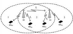
目前,BS与用户终端(SS或MSS)之间直接进行通信,以进行信息的交互。这样,由于基站的覆盖范围有限,导致整个网络的覆盖范围受限;同时,还由于用户终端直接与BS通信,因此,同一BS需要同时处理大量用户的通信信息,这必然导致针对用户终端的信息处理性能受到负面影响,进而导致用户终端的吞吐量降低,影响整个网络的通信性能。 Currently, the BS communicates directly with the user terminal (SS or MSS) to exchange information. In this way, due to the limited coverage of the base station, the coverage of the entire network is limited; at the same time, because the user terminal directly communicates with the BS, the same BS needs to process the communication information of a large number of users at the same time, which will inevitably lead to information on the user terminal. Processing performance is negatively impacted, which in turn leads to reduced throughput at user terminals and affects communication performance across the network. the
发明内容Contents of the invention
本发明的目的是提供一种无线中转通信系统及方法,从而可以实现BS与用户终端(SS或MSS)之间的中转通信,进而扩大BS的覆盖范围,增加用户终端的吞吐量。 The purpose of the present invention is to provide a wireless relay communication system and method, so as to realize relay communication between BS and user terminal (SS or MSS), further expand the coverage of BS, and increase the throughput of user terminal. the
本发明提供了一种无线中转通信系统,包括:基站BS、用户终端和中转站RS,所述的BS设置有与RS通信的接口,所述的RS设置有与用户终端和BS通信的接口,所述的用户终端则设置有与RS通信的接口,所述的BS、RS和用户终端之间通过所述接口通信。 The present invention provides a wireless transfer communication system, comprising: a base station BS, a user terminal and a transfer station RS, the BS is provided with an interface for communicating with the RS, and the RS is provided with an interface for communicating with the user terminal and the BS, The user terminal is provided with an interface for communicating with the RS, and the BS, RS and the user terminal communicate through the interface. the
本发明所述的系统中还可选地包含以下技术特征: The system of the present invention also optionally includes the following technical features:
所述的BS还设置有与用户终端通信的接口,且所述用户终端设置有与BS通信的接口,BS通过所述接口与用户终端之间直接通信。 The BS is also provided with an interface for communicating with the user terminal, and the user terminal is provided with an interface for communicating with the BS, and the BS directly communicates with the user terminal through the interface. the
所述BS、RS和用户终端之间采用同频点进行通信,且所述BS分别通过上、下行子帧与用户终端或RS通信,所述RS分别通过上、下子帧与用户终端或BS通信。 The BS, RS and user terminal communicate with each other using the same frequency point, and the BS communicates with the user terminal or RS through uplink and downlink subframes respectively, and the RS communicates with the user terminal or BS through uplink and downlink subframes respectively . the
若所述的BS、RS及用户终端之间基于时分双工TDD通信,则所述的BS、RS和用户终端三个实体中分别设置有TDD无线发射机物理层单元和TDD无线接收机物理层单元,且所述的各TDD无线发射机物理层单元分别提供有与其他实体中的TDD无线接收机物理层单元通信的通信接口,所述的各TDD接收机物理层单元分别提供有与其他实体中的TDD无线发射机物理层单元通信的通信接口;或者,所述RS中设置有第一TDD无线收发机和第二TDD无线收发机,其中,第一TDD无线收发机包含采用相同的第一频率的TDD无线接收机物理层单元和TDD无线发射机物理单元,并与BS中的FDD无线发射机物理层单元,以及用户终端中的FDD无线接收机物理层单元对应并保持收发帧同步,第二TDD无线收发机包含采用相同的第二频率的TDD无线接收机物理层单元和TDD无线发射机物理单元,且与用户终端中的FDD无线发射机物理层单元,以及BS中的FDD无线接收机物理层单元对应并保持收发帧同步; If the BS, RS and user terminal are based on time division duplex TDD communication, the three entities of the BS, RS and user terminal are respectively provided with a TDD wireless transmitter physical layer unit and a TDD wireless receiver physical layer unit, and each of the TDD wireless transmitter physical layer units is provided with a communication interface for communicating with the TDD wireless receiver physical layer units in other entities, and each of the TDD receiver physical layer units is provided with communication interfaces with other entities The communication interface of the TDD wireless transmitter physical layer unit communication in the RS; or, the RS is provided with a first TDD wireless transceiver and a second TDD wireless transceiver, wherein the first TDD wireless transceiver includes the same first The TDD wireless receiver physical layer unit and the TDD wireless transmitter physical layer unit of the frequency correspond to the FDD wireless transmitter physical layer unit in the BS and the FDD wireless receiver physical layer unit in the user terminal and maintain frame synchronization for sending and receiving. The two TDD wireless transceivers include a TDD wireless receiver physical layer unit and a TDD wireless transmitter physical layer unit using the same second frequency, and are compatible with the FDD wireless transmitter physical layer unit in the user terminal and the FDD wireless receiver in the BS The physical layer unit corresponds to and maintains the synchronization of sending and receiving frames;
或者, or,
若所述的BS、RS及用户终端之间基于时分复用TDM/时分复用接入TDMA-频分双工FDD通信,则 所述RS中包括第一TDM/TDMA-FDD无线收发机和第二TDM/TDMA-FDD无线收发机,其中,RS中的第一TDM/TDMA-FDD无线收发机包含的TDM-FDD无线发射机物理层单元和TDMA-FDD无线接收机物理单元与用户终端中的TDM-FDD无线接收机物理层单元和TDMA-FDD无线发射机物理层单元对应并保持收发帧同步,RS中的第二无线TDM/TDMA-FDD收发机包含的TDMA-FDD无线发射机物理层单元和TDM-FDD无线接收机物理单元与BS中的TDMA-FDD无线接收机物理层单元和TDM-FDD无线发射机物理层单元对应并保持收发帧同步; If the BS, RS and user terminal are based on time division multiplexing TDM/time division multiplexing access TDMA-frequency division duplex FDD communication, then the RS includes the first TDM/TDMA-FDD wireless transceiver and the second Two TDM/TDMA-FDD wireless transceivers, wherein the first TDM/TDMA-FDD wireless transceiver in the RS includes the TDM-FDD wireless transmitter physical layer unit and the TDMA-FDD wireless receiver physical unit and the user terminal The physical layer unit of the TDM-FDD wireless receiver corresponds to the physical layer unit of the TDMA-FDD wireless transmitter and maintains frame synchronization for sending and receiving, and the physical layer unit of the TDMA-FDD wireless transmitter included in the second wireless TDM/TDMA-FDD transceiver in the RS The physical unit of the TDM-FDD wireless receiver corresponds to the physical layer unit of the TDMA-FDD wireless receiver and the physical layer unit of the TDM-FDD wireless transmitter in the BS and maintains the synchronization of sending and receiving frames;
或者, or,
若所述的BS、RS及用户终端之间基于OFDMA-FDD通信,则所述RS中包括第一OFDMA-FDD无线收发机和第二OFDMA-FDD无线收发机,其中,RS中的第一OFDMA-FDD无线收发机包含的第一OFDMA-FDD无线发射机物理层单元和第一OFDMA-FDD无线接收机物理单元与用户终端中的OFDMA-FDD无线接收机物理层单元和OFDMA-FDD无线发射机物理层单元对应并保持收发帧同步;RS中的第二OFDMA-FDD无线收发机包含的第二OFDMA-FDD无线发射机物理层单元和第二OFDMA-FDD无线接收机物理单元与BS中的OFDMA-FDD无线接收机物理层单元和OFDMA-FDD无线发射机物理层单元对应并保持收发帧同步; If the communication between the BS, the RS and the user terminal is based on OFDMA-FDD, the RS includes a first OFDMA-FDD wireless transceiver and a second OFDMA-FDD wireless transceiver, wherein the first OFDMA-FDD transceiver in the RS -The physical layer unit of the first OFDMA-FDD wireless transmitter and the physical layer unit of the first OFDMA-FDD wireless receiver included in the FDD wireless transceiver and the physical layer unit of the OFDMA-FDD wireless receiver and the OFDMA-FDD wireless transmitter in the user terminal The physical layer unit corresponds to and maintains the synchronization of the sending and receiving frame; the second OFDMA-FDD wireless transmitter physical layer unit and the second OFDMA-FDD wireless receiver physical unit contained in the second OFDMA-FDD wireless transceiver in the RS are the same as the OFDMA in the BS - The physical layer unit of the FDD wireless receiver corresponds to the physical layer unit of the OFDMA-FDD wireless transmitter and maintains the synchronization of sending and receiving frames;
或者, or,
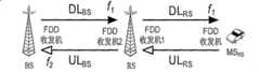
若所述的BS、RS及用户终端之间基于FDD通信,则RS和BS中分别包括FDD无线收发机,该FDD无线收发机包括FDD无线发射机物理层单元和FDD无线接收机物理层单元,RS以FDD方式同BS和用户终端进行无线通信,所述RS中的FDD无线收发机上行和BS中的FDD无线收发机下行采用相同的频率,RS中的FDD无线收发机下行和BS中的FDD无线收发机上行采用相同的频率;或者,RS中包括FDD无线收发机,所述RS中的FDD无线收发机上行和BS中的FDD无线收发机下行采用相同的频率,RS中的FDD无线收发机下行和BS中的FDD无线收发机上行采用相同的频率,其中,用户终端中的第一FDD无线收发机包含的第一FDD无线发射机物理层单元和第一FDD无线接收机物理单元与BS中的FDD无线接收机物理层单元和FDD无线发射机物理层单元对应,用户终端中的第二FDD无线收发机包含的第二FDD无线发射机物理层单元和第二FDD无线接收机物理单元与RS中的FDD无线接收机物理层单元和FDD无线发射机物理层单元对应。 If the communication between the BS, the RS and the user terminal is based on FDD, the RS and the BS respectively include an FDD wireless transceiver, and the FDD wireless transceiver includes an FDD wireless transmitter physical layer unit and an FDD wireless receiver physical layer unit, The RS performs wireless communication with the BS and the user terminal in the FDD mode. The FDD wireless transceiver in the RS uses the same frequency for uplink and the FDD wireless transceiver in the BS for downlink, and the FDD wireless transceiver in the RS for downlink and the FDD wireless transceiver in the BS. The uplink of the wireless transceivers adopts the same frequency; or, the RS includes an FDD wireless transceiver, the FDD wireless transceiver in the RS uses the same frequency for the uplink and the downlink of the FDD wireless transceiver in the BS, and the FDD wireless transceiver in the RS The downlink and the uplink of the FDD wireless transceiver in the BS use the same frequency, wherein the first FDD wireless transmitter physical layer unit and the first FDD wireless receiver physical layer unit contained in the first FDD wireless transceiver in the user terminal are the same as those in the BS The FDD wireless receiver physical layer unit corresponds to the FDD wireless transmitter physical layer unit, and the second FDD wireless transmitter physical layer unit and the second FDD wireless receiver physical layer unit contained in the second FDD wireless transceiver in the user terminal correspond to the RS The FDD wireless receiver physical layer unit corresponds to the FDD wireless transmitter physical layer unit. the
所述的BS、RS和用户终端中还分别设置有与所述的物理层单元连接通信的数据链路层单元,而且,所述的BS中还设置有与上级设置连接通信的有线传输处理单元,用于与上一级设备或各基站设备之间进行信息交互。 The BS, RS, and user terminal are also respectively provided with a data link layer unit connected to and communicated with the physical layer unit, and the BS is also provided with a wired transmission processing unit connected to and communicated with the upper level , for information exchange with upper-level equipment or each base station equipment. the
所述的BS还提供与用户终端通信的接口,所述BS通过采用预定的信道编码和调制方式,或者,采用预定的发射功率值将前导码Preamble、帧控制头FCH、下行映射表DL-MAP和上行映射表UL-MAP信息直接从该接口将信息发送给用户终端。 The BS also provides an interface for communicating with the user terminal. The BS converts the preamble Preamble, the frame control header FCH, and the downlink mapping table DL-MAP by using a predetermined channel coding and modulation method, or using a predetermined transmission power value. and the uplink mapping table UL-MAP information are directly sent to the user terminal through this interface. the
本发明还提供了一种无线中转通信的实现方法,包括: The present invention also provides a method for realizing wireless relay communication, including:
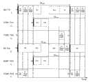
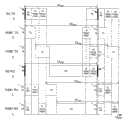
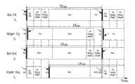
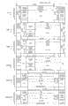
在BS物理层帧结构的下行子帧和上行子帧中分别设置下行中转区和上行中转区,在RS物理层帧结构的上行子帧和下行子帧中分别设置下行中转区和上行中转区,用于定义BS与RS之间通信的中转时隙或中转子信道和OFDMA符号组合; The downlink transit area and the uplink transit area are respectively set in the downlink subframe and the uplink subframe of the BS physical layer frame structure, and the downlink transit area and the uplink transit area are respectively set in the uplink subframe and the downlink subframe of the RS physical layer frame structure, Used to define the transit time slot or sub-channel and OFDMA symbol combination for communication between BS and RS;
在BS、RS及用户终端之间基于设置的BS和RS的上、下行物理层帧进行无线中转通信。 Wireless transfer communication is performed between BS, RS and user terminals based on the uplink and downlink physical layer frames of BS and RS set. the
本发明还可选地包括以下技术特征: The present invention also optionally includes the following technical features:
在BS物理层帧结构的下行子帧和上行子帧中分别采用TDM方式下行中转区和上行中转区。 In the downlink subframe and uplink subframe of the BS physical layer frame structure, the TDM mode downlink transit area and uplink transit area are adopted respectively. the
当RS中设置有两个TDM/TDMA-FDD或OFDMA-FDD无线收发机时,则在与BS对应的RS中的TDM/TDMA-FDD或OFDMA-FDD无线收发机的物理层帧结构的上行子帧和下行子帧中分别设置下行中转区和上行中转区,用于定义BS和RS之间的中转时隙,或者,用于定义BS和RS之间的中转子信道和OFDMA符号组合; When two TDM/TDMA-FDD or OFDMA-FDD wireless transceivers are set in the RS, then in the uplink subsection of the physical layer frame structure of the TDM/TDMA-FDD or OFDMA-FDD wireless transceiver in the RS corresponding to the BS The downlink transfer area and the uplink transfer area are respectively set in the frame and the downlink subframe, which are used to define the transfer time slot between the BS and the RS, or to define the intermediate subchannel and OFDMA symbol combination between the BS and the RS;
当RS中设置有两个TDD无线收发机时,则在RS的第一TDD无线收发机的物理层帧结构的上行子帧和第二TDD无线收发机的物理层帧结构的下行子帧中分别设置下行中转区和上行中转区,用于定义BS和RS间进行信息交互的子信道和OFDMA符号组合; When two TDD wireless transceivers are arranged in the RS, then in the uplink subframe of the physical layer frame structure of the first TDD wireless transceiver of the RS and the downlink subframe of the physical layer frame structure of the second TDD wireless transceiver respectively Set the downlink transit area and the uplink transit area, which are used to define the combination of subchannels and OFDMA symbols for information exchange between BS and RS;
当RS中设置有一个FDD无线收发机时,则在中转站RS的FDD无线接收机的物理层帧结构的上行子帧中设置下行中转区,用于定义RS接收BS的下行中转区的中转时隙,或者,用于定义BS和RS的下行中转区的中转子信道和OFDMA符号组合;在RS的FDD无线发射机的物理层帧结构的下行子帧中设置上行中转区,用于定义RS接收BS的上行中转区的中转时隙,或者,用于定义BS和RS的上行中转区的中转子信道和OFDMA符号组合。 When an FDD wireless transceiver is set in the RS, the downlink transfer area is set in the uplink subframe of the physical layer frame structure of the FDD wireless receiver of the transfer station RS, which is used to define the transfer time of the RS receiving the downlink transfer area of the BS slots, or the sub-channel and OFDMA symbol combination used to define the downlink transit area of the BS and RS; the uplink transit area is set in the downlink subframe of the physical layer frame structure of the FDD wireless transmitter of the RS, which is used to define the RS receiving The transit time slot of the uplink transit zone of the BS, or the subchannel and OFDMA symbol combination used to define the uplink transit zone of the BS and the RS. the
所述的方法还包括: The method also includes:
当RS中设置有单个FDD无线收发机,则在BS的上行中转区对应的期间内,属于BS的用户终端不设置发送时隙或发送子信道和OFDMA符号组合,在BS的下行中转区对应的期间内,属于RS的用户终端不设置发送时隙或发送子信道和OFDMA符号组合; When a single FDD wireless transceiver is set in the RS, during the period corresponding to the uplink transit area of the BS, the user terminal belonging to the BS does not set a transmission time slot or transmit a combination of subchannels and OFDMA symbols, and in the period corresponding to the downlink transit area of the BS During the period, the user terminal belonging to the RS does not set a transmission slot or transmit a combination of subchannels and OFDMA symbols;
当RS中设置有两个OFDMA-FDD无线收发机,则在在BS的上行中转区对应的期间,用户终端不设置发送子信道和OFDMA符号组合,RS不设置任何接收子信道和OFDMA符号组合;在BS的下行中转区对应的期间,RS不设置发送子信道和OFDMA符号组合; When two OFDMA-FDD wireless transceivers are set in the RS, during the period corresponding to the uplink transit area of the BS, the user terminal does not set a combination of sending subchannels and OFDMA symbols, and the RS does not set any combination of receiving subchannels and OFDMA symbols; During the period corresponding to the downlink transit area of the BS, the RS does not set the combination of sending subchannels and OFDMA symbols;
当RS中设置有单个TDD无线收发机时,则在所述的BS的物理层帧结构中的上行中转区和下行中转区对应,而且,在BS的下行中转区和上行中转区对应的期间,用户终端不设置接收或发送时隙或子信道和OFDMA符号组合;而且,若RS通过中转时隙进行信息的传递,则所述的BS的物理层帧结构中的上行中转区和下行中转区的时隙分别与RS的物理层帧结构中的上行中转区和下行中转区的时隙对应; When a single TDD wireless transceiver is set in the RS, the uplink transit area and the downlink transit area in the physical layer frame structure of the BS correspond, and, during the period when the downlink transit area of the BS corresponds to the uplink transit area, The user terminal does not set the combination of receiving or sending time slots or sub-channels and OFDMA symbols; moreover, if the RS transmits information through the transfer time slot, the uplink transfer area and the downlink transfer area in the physical layer frame structure of the BS The time slots correspond to the time slots of the uplink transit area and the downlink transit area in the physical layer frame structure of the RS respectively;
当RS中设置有两个TDM/TDMA-FDD无线收发机,则所述的BS的下行中转区与RS中与BS对应的TDM/TDMA-FDD无线收发机的下行中转区的时隙和频率关系对应,所述的BS的上行中转区和RS中与BS对应的TDM/TDMA-FDD无线收发机的上行中转区的时隙和频率关系对应,而且,在BS的上行中转区对应的期间,用户终端不设置发送时隙,RS不设置接收时隙; When two TDM/TDMA-FDD wireless transceivers are set in the RS, the time slot and frequency relationship between the downlink transit area of the BS and the downlink transit area of the TDM/TDMA-FDD wireless transceiver corresponding to the BS in the RS Correspondingly, the uplink transit area of the BS corresponds to the time slot and frequency relationship of the uplink transit area of the TDM/TDMA-FDD wireless transceiver corresponding to the BS in the RS, and, during the period corresponding to the uplink transit area of the BS, the user The terminal does not set the sending time slot, and the RS does not set the receiving time slot;
当RS中存在两个TDD无线收发机时,则在所述BS的上行中转区对应的期间,BS和RS覆盖下的用户终端均不设置发送子信道和OFDMA符号组合,RS不设置接收子信道和OFDMA符号组合。 When there are two TDD wireless transceivers in the RS, during the period corresponding to the uplink transit area of the BS, the user terminals under the coverage of the BS and the RS do not set the sending subchannel and OFDMA symbol combination, and the RS does not set the receiving subchannel combined with OFDMA symbols. the
所述的方法还包括: The method also includes:
当存在至少两个RS时,该至少两个RS通过不同的子信道和OFDMA符号组合或者采用不同的TDM方式共享下行或上行中转区; When there are at least two RSs, the at least two RSs share the downlink or uplink transit area through different combinations of subchannels and OFDMA symbols or using different TDM methods;
且当采用不同的子信道和OFDMA符号组合共享时,不同的RS只在下行中转区中相应的子信道和 OFDMA符号组合中发送BS的中转数据,在其它子信道和OFDMA符号组合中不安排发送BS的中转数据,不同的RS的FDD无线接收机只在下行中转区中相应的子信道和OFDMA符号组合中接收BS的中转数据,在其它子信道和OFDMA符号组合中不安排接收BS的中转数据。 And when different sub-channels and OFDMA symbol combinations are used for sharing, different RSs only transmit the transfer data of the BS in the corresponding sub-channel and OFDMA symbol combinations in the downlink transfer area, and do not arrange to send in other sub-channels and OFDMA symbol combinations. BS relay data, different RS FDD wireless receivers only receive BS relay data in the corresponding sub-channel and OFDMA symbol combination in the downlink relay area, and do not arrange to receive BS relay data in other sub-channel and OFDMA symbol combinations . the
本发明中,当RS中设置有两个无线收发机时,对于存在至少两个RS的情况,各RS之间利用其与BS对应的收发机通过不同的子信道和OFDMA符号组合或者采用不同的TDM方式共享下行或上行中转区。 In the present invention, when there are two wireless transceivers in the RS, for the situation that there are at least two RSs, the transceivers corresponding to the BS are used between each RS to combine different subchannels and OFDMA symbols or use different The TDM mode shares the downlink or uplink transit area. the
所述的方法还包括: The method also includes:
在BS的物理层帧结构的下行子帧中设置下行中转广播子信道或中转广播时隙,用于定义由BS广播给RS的下行子信道和OFDMA符号组合或下行时隙; Set the downlink relay broadcast subchannel or relay broadcast time slot in the downlink subframe of the physical layer frame structure of the BS, which is used to define the downlink subchannel and OFDMA symbol combination or downlink time slot broadcast by the BS to the RS;
在RS的物理层帧结构的下行子帧中设置下行中转广播子信道或中转广播接收时隙,用于定义接收BS下行中转广播的RS上行子信道和OFDMA符号组合或上行时隙;若RS中设置有两个无线收发机,则在其与BS对应的收发机的物理层帧结构中设置下行中转广播子信道或中转广播接收时隙; Set the downlink relay broadcast subchannel or relay broadcast receiving time slot in the downlink subframe of the physical layer frame structure of the RS, which is used to define the RS uplink subchannel and OFDMA symbol combination or uplink time slot for receiving the BS downlink relay broadcast; if in the RS If there are two wireless transceivers, set the downlink relay broadcast sub-channel or relay broadcast receiving time slot in the physical layer frame structure of the transceiver corresponding to the BS;
且所述在BS和RS中设置的下行中转广播子信道或中转广播时隙或中转广播接收时隙在每一帧中选择设置。 And the downlink relay broadcast sub-channel or relay broadcast time slot or relay broadcast receiving time slot set in the BS and RS is selected and set in each frame. the
本发明中,当RS通过中转子信道和OFDMA符号组合进行信息的传递,则所述的方法还包括: In the present invention, when the RS transmits information through the combination of the rotor channel and the OFDMA symbol, the method also includes:
在BS的物理层帧结构的上行子帧的上行中转区中定义中转测距子信道,定义用于RS的初始接入测距、周期性测距、带宽请求的BS中转测距接收子信道和OFDMA符号组合,该中转测距子信道还可选地作为用户终端的初始接入测距、周期性测距、带宽请求测距子信道用; Define the relay ranging subchannel in the uplink transit area of the uplink subframe of the physical layer frame structure of the BS, and define the BS transit ranging receiving subchannel for initial access ranging, periodic ranging, and bandwidth request of the RS and OFDMA symbol combination, the relay ranging sub-channel can also optionally be used as the initial access ranging, periodic ranging, and bandwidth request ranging sub-channel of the user terminal;
在RS的物理层帧结构的下行中转区中设置中转测距子信道,用于定义RS的初始接入测距、周期性测距、带宽请求的RS中转测距发送子信道和OFDMA符号组合;若RS中设置有两个无线收发机,则在其与BS对应的收发机的物理层帧结构中设置所述的中转测距子信道; The relay ranging subchannel is set in the downlink transit area of the physical layer frame structure of the RS, which is used to define the initial access ranging, periodic ranging, and bandwidth request of the RS transit ranging sending subchannel and OFDMA symbol combination; If two wireless transceivers are set in the RS, set the transit ranging sub-channel in the physical layer frame structure of the transceiver corresponding to the BS;
所述在BS和RS中设置的中转测距子信道的时频关系一一对应,保持同步,并在每一帧中选择设置。 The time-frequency relationship of the transit ranging sub-channels set in the BS and RS correspond one-to-one, keep synchronization, and are selected and set in each frame. the
所述的方法还包括: The method also includes:
在BS的物理层帧结构的上行子帧中定义测距子信道,定义用于用户终端的初始接入测距、周期性测距、带宽请求的BS测距接收子信道和OFDMA符号组合; Define the ranging subchannel in the uplink subframe of the physical layer frame structure of the BS, and define the BS ranging receiving subchannel and OFDMA symbol combination for initial access ranging, periodic ranging, and bandwidth request of the user terminal;
当BS无法与RS覆盖下的用户终端直接通信时,在RS的FDD无线接收机的物理层帧结构的上行子帧中设置测距子信道,定义用于用户终端的初始接入测距、周期性测距、带宽请求的RS测距接收子信道和OFDMA符号组合;若RS中设置有两个无线收发机,则在RS与用户终端对应的收发机的物理层帧结构中设置所述的测距子信道。 When the BS cannot directly communicate with the user terminal under the coverage of the RS, the ranging subchannel is set in the uplink subframe of the physical layer frame structure of the FDD wireless receiver of the RS, and the initial access ranging and period for the user terminal are defined The RS ranging reception subchannel and OFDMA symbol combination of the random ranging and the bandwidth request; if two wireless transceivers are set in the RS, then set the measurement in the physical layer frame structure of the transceiver corresponding to the RS and the user terminal subchannel. the
本发明中,当RS通过中转时隙进行信道传递时,所述方法还包括: In the present invention, when the RS transmits the channel through the transit time slot, the method also includes:
在BS和RS的物理层帧结构的下行子帧中定义下行干扰时隙,用于定义BS和RS各自覆盖区域中的下行数据时隙,所述的各自覆盖的区域包括仅由BS和RS各自覆盖的重叠区域,或者,包括由BS和RS各自覆盖的不重叠区域以及BS和RS各自覆盖的重叠区域;若RS中设置有两个无线收发机,则在RS与用户终端对应的收发机的物理层帧结构中设置所述的下行干扰时隙。 The downlink interference time slot is defined in the downlink subframe of the physical layer frame structure of the BS and the RS, which is used to define the downlink data time slot in the respective coverage areas of the BS and the RS, and the respective covered areas include only the BS and the RS The overlapping areas covered, or, include the non-overlapping areas covered by the BS and the RS respectively and the overlapping areas covered by the BS and the RS respectively; The downlink interference time slot is set in the physical layer frame structure. the
所述的BS的下行干扰时隙与RS的下行干扰时隙在时隙上不重叠,且当有至少两个RS时,所述的至少两个RS采用TDM的方式共享所述下行干扰时隙,且在BS和RS的每帧中选择设置所述下行干扰时隙。 The downlink interference time slot of the BS and the downlink interference time slot of the RS do not overlap in time slots, and when there are at least two RSs, the at least two RSs use TDM to share the downlink interference time slot , and select and set the downlink interference time slot in each frame of the BS and RS. the
本发明中,当RS通过中转时隙进行信道传递时,所述方法还包括: In the present invention, when the RS transmits the channel through the transit time slot, the method also includes:
在BS和RS的上行子帧中设置上行或下行无干扰时隙,和/或,在BS和RS的下行子帧中设置上行或下行无干扰时隙,用于定义仅由BS和RS各自覆盖区域的下行或上行数据时隙;若在RS中存在两个无线收发机,则在RS中与用户终端对应的无线收发机的物理层帧结构中设置所述上行干扰时隙或上行无干扰时隙; Set uplink or downlink non-interference time slots in the uplink subframes of BS and RS, and/or set uplink or downlink non-interference time slots in the downlink subframes of BS and RS, used to define only covered by BS and RS The downlink or uplink data time slot of the area; if there are two wireless transceivers in the RS, set the uplink interference time slot in the physical layer frame structure of the wireless transceiver corresponding to the user terminal in the RS or when there is no interference in the uplink gap;
而且,BS的下行无干扰时隙和RS的下行无干扰时隙,以及BS的上行无干扰时隙和RS的上行无干扰时隙均可重叠设置。 Moreover, the downlink non-interference time slots of the BS and the downlink non-interference time slots of the RS, and the uplink non-interference time slots of the BS and the uplink non-interference time slots of the RS can be set overlappingly. the
所述的BS和RS的上行干扰时隙在时间上互不重叠。 The uplink interference time slots of the BS and RS do not overlap each other in time. the
所述的方法还包括: The method also includes:
在BS,或BS和RS的物理层帧结构的下行子帧中定义下行子帧头或下行子帧头时隙,所述的下行子帧头或下行子帧头时隙为下行子帧的开始,用于定义发送用户同步信息的子信道和OFDMA符号组合或时隙和发送指示信息的子信道和OFDMA符号组合或时隙,以指示BS,或BS和RS物理层帧结构下行子帧和上行子帧的各子信道和OFDMA符号组合的位置和使用方法,或者,各时隙的位置和使用方法,该下行子帧头在每帧中均设置;其中,在RS的物理层帧结构的下行子帧中定义的下行子帧头或下行子帧头时隙在时间上滞后于所述在BS的物理层帧结构的下行子帧中定义的下行子帧头或下行子帧头时隙,且对于RS的下行子帧头期间,BS不能安排任何接收子信道和OFDMA符号组合,对于RS的下行帧头时隙不与BS的下行帧头时隙重叠,并且设置于BS的上行子帧的无干扰时隙内;若RS中设置有两个无线收发机,则在RS与用户终端对应的收发机的物理层帧结构中设置所述的下行子帧头或下行子帧头时隙; Define a downlink subframe header or a downlink subframe header time slot in the downlink subframe of the physical layer frame structure of the BS or the BS and the RS, and the downlink subframe header or the downlink subframe header time slot is the beginning of the downlink subframe , used to define the subchannel and OFDMA symbol combination or time slot for sending user synchronization information and the subchannel and OFDMA symbol combination or time slot for sending indication information, to indicate the BS, or the BS and RS physical layer frame structure downlink subframe and uplink The position and use method of each subchannel and OFDMA symbol combination of the subframe, or the position and use method of each time slot, the downlink subframe header is set in each frame; wherein, in the downlink of the physical layer frame structure of the RS The downlink subframe header or the downlink subframe header time slot defined in the subframe lags behind the downlink subframe header or the downlink subframe header time slot defined in the downlink subframe of the physical layer frame structure of the BS in time, and For the downlink subframe header period of the RS, the BS cannot arrange any combination of receiving subchannels and OFDMA symbols, the downlink frame header time slot of the RS does not overlap with the downlink frame header time slot of the BS, and no In the interference time slot; if two wireless transceivers are set in the RS, set the downlink subframe header or the downlink subframe header time slot in the physical layer frame structure of the transceiver corresponding to the RS and the user terminal;
在RS的物理层帧结构中设置下行子帧头接收或下行子帧头接收时隙,用于定义接收BS的下行子帧头的子信道和OFDMA符号组合或下行子帧头时隙的时隙,该下行子帧头接收或下行子帧头接收时隙和所述BS的下行子帧头或下行子帧头接收时隙的时频或时隙关系一一对应,完全同步;若RS中设置有两个无线收发机,则在RS与BS对应的收发机的物理层帧结构中设置所述的下行子帧头接收或下行子帧头接收时隙。 Set the downlink subframe header reception or downlink subframe header reception time slot in the physical layer frame structure of the RS, which is used to define the subchannel and OFDMA symbol combination of the downlink subframe header of the receiving BS or the time slot of the downlink subframe header time slot , the downlink subframe header receiving or downlink subframe header receiving time slot is in one-to-one correspondence with the time-frequency or time slot relationship of the downlink subframe header or downlink subframe header receiving time slot of the BS, and is completely synchronized; if RS is set If there are two wireless transceivers, the downlink subframe header reception or the downlink subframe header reception time slot is set in the physical layer frame structure of the transceivers corresponding to the RS and the BS. the
所述的下行子帧包括: The downlink subframe includes:
正交频分复用或单载波帧中的前导码preamble、帧控制头FCH burst、下行映射表DL-MAP和/或上行映射表UL-MAP。 Preamble preamble, frame control header FCH burst, downlink mapping table DL-MAP and/or uplink mapping table UL-MAP in orthogonal frequency division multiplexing or single carrier frame. the
本发明中,当存在多个RS时,所述的方法还包括: In the present invention, when there are multiple RSs, the method also includes:
所述的RS设置的所述的下行子帧与其他RS的上行子帧不重叠; The downlink subframe set by the RS does not overlap with the uplink subframes of other RSs;
或者, or,
RS的下行帧头时隙与其他RS的下行帧头时隙和下行干扰时隙不重叠;或者,不同RS的下行帧头时隙在时间上完全重叠同步,且下行帧头时隙内容相同,RS的下行帧头时隙与其他RS的下行干扰时隙不重叠设置。 The downlink frame header slots of the RS do not overlap with the downlink frame header slots and downlink interference slots of other RSs; or, the downlink frame header slots of different RSs are completely overlapped and synchronized in time, and the contents of the downlink frame header slots are the same, The downlink frame header time slot of the RS is not overlapped with the downlink interference time slots of other RSs. the
若所述的RS中设置的两无线收发机以不同的频率分别进行下行和上行通信时,则RS在用于向用户终端发送下行信息的无线收发机的物理层帧结构的下行子帧中设置下行子帧头。 If the two wireless transceivers set in the RS perform downlink and uplink communications respectively at different frequencies, the RS is set in the downlink subframe of the physical layer frame structure of the wireless transceiver used to send downlink information to the user terminal Downlink subframe header. the
所述的方法还包括: The method also includes:
当存在至少两个RS时,在RS下行子帧头期间,其它RS的物理层帧结构的下行子帧不安排任何发送子信道和OFDMA符号组合,或者,RS的下行帧头时隙不与其他RS的下行帧头时隙和下行干扰时隙重叠; When there are at least two RSs, during the RS downlink subframe header period, the downlink subframes of the physical layer frame structure of other RSs do not arrange any combination of sending subchannels and OFDMA symbols, or the downlink frame header slots of RSs are not combined with other RSs. The downlink frame header time slot of the RS overlaps with the downlink interference time slot;
或者, or,
当存在至少两个RS时,若不同RS的下行子帧头在时间上完全重叠同步,且其下行子帧头内容相同,或者,不同RS的下行帧头时隙在时间上完全重叠同步,且下行帧头时隙内容相同,RS的下行帧头时隙不与其他RS的下行干扰时隙重叠。 When there are at least two RSs, if the downlink subframe headers of different RSs are completely overlapped and synchronized in time, and the content of the downlink subframe headers is the same, or the downlink frame headers of different RSs are completely overlapped and synchronized in time, and The contents of the downlink frame header slots are the same, and the downlink frame header slots of the RS do not overlap with the downlink interference slots of other RSs. the
本发明中,当RS通过中转时隙进行信息的传递,则所述的方法还包括: In the present invention, when the RS transmits information through the transit time slot, the method also includes:
所述BS的下行中转区和RS的下行中转区的时隙和频率关系一一对应,所述BS的上行中转区和RS的上行中转区的时隙和频率关系一一对应,所述在BS和RS中设置的上行和下行中转区在每帧中选择设置。 There is a one-to-one correspondence between the time slot and frequency relationship between the downlink transit area of the BS and the downlink transit area of the RS, and the one-to-one correspondence between the time slot and frequency relationship between the uplink transit area of the BS and the uplink transit area of the RS. The uplink and downlink transit areas set in the RS are selected and set in each frame. the
本发明中,当RS通过中转时隙进行信息的传递,所述方法还包括: In the present invention, when the RS transmits information through the transit time slot, the method also includes:
在BS的物理层帧结构的上行子帧中设置上行竞争时隙,该上行竞争时隙中包含初始测距竞争时隙和带宽请求竞争时隙,该上行竞争时隙在每帧中设置; Set the uplink contention time slot in the uplink subframe of the physical layer frame structure of the BS, the uplink contention time slot includes the initial ranging contention time slot and the bandwidth request contention time slot, and the uplink contention time slot is set in each frame;
当BS无法与RS覆盖区域中的用户终端直接通信时,在RS的物理层帧结构的上行子帧中设置上行竞争时隙,该上行竞争时隙中包含初始测距竞争时隙和带宽请求竞争时隙;若RS中设置有两个无线收发机,则在RS与用户终端对应的收发机的物理层帧结构中设置所述的上行竞争时隙。 When the BS cannot directly communicate with the user terminal in the coverage area of the RS, an uplink contention time slot is set in the uplink subframe of the physical layer frame structure of the RS, and the uplink contention time slot includes the initial ranging contention time slot and the bandwidth request contention Time slots; if two wireless transceivers are set in the RS, the uplink contention time slots are set in the physical layer frame structure of the transceivers corresponding to the RS and the user terminal. the
所述的方法还包括:在RS的物理层帧结构中设置上行竞争发送时隙,用于定义RS发送的用于竞争BS的上行竞争时隙的时隙,该上行竞争发送时隙和所述BS的上行竞争时隙的频率完全重叠同步,且该上行竞争时隙在每帧中设置;若RS中设置有两个无线收发机,则在RS与BS对应的收发机的物理层帧结构中设置所述的上行竞争发送时隙。 The method further includes: setting an uplink contention sending time slot in the physical layer frame structure of the RS, which is used to define a time slot sent by the RS for competing for the uplink contention time slot of the BS, and the uplink contention sending time slot and the The frequency of the uplink contention time slots of the BS is completely overlapped and synchronized, and the uplink contention time slots are set in each frame; if two wireless transceivers are set in the RS, then in the physical layer frame structure of the transceivers corresponding to the RS and the BS Set the uplink contention sending time slot. the
本发明中,当RS存在两个无线收发机时,所述的方法还包括: In the present invention, when there are two wireless transceivers in the RS, the method also includes:
当RS中存在两个OFDMA-FDD无线收发机时, When there are two OFDMA-FDD wireless transceivers in the RS,
在BS或RS中与用户终端对应的无线收发机的物理层帧结构的下行子帧中,除下行子帧头、BS的下行中转区和RS中与用户终端对应的OFDMA-FDD无线发射机在BS的下行子帧头、BS的下行中转区的对应期间外,BS和不同的RS通过不同的子信道和OFDMA符号组合共享下行子帧的余下部分;和/或,在BS或RS中与用户终端对应的OFDMA-FDD无线收发机物理层帧结构的上行子帧中,除BS的上行中转区和RS中与用户终端对应的OFDMA-FDD无线接收机在BS的上行中转区对应期间外,BS和不同的RS通过不同的子信道和OFDMA符合组合共享上行子帧的其余部分; In the downlink subframe of the physical layer frame structure of the wireless transceiver corresponding to the user terminal in the BS or RS, except for the downlink subframe header, the downlink transit area of the BS, and the OFDMA-FDD wireless transmitter corresponding to the user terminal in the RS Outside the corresponding period of the downlink subframe head of the BS and the downlink transit area of the BS, the BS and different RSs share the rest of the downlink subframe through different combinations of subchannels and OFDMA symbols; In the uplink subframe of the OFDMA-FDD wireless transceiver physical layer frame structure corresponding to the terminal, except for the uplink transit area of the BS and the corresponding period of the OFDMA-FDD wireless receiver corresponding to the user terminal in the RS in the uplink transit area of the BS, the BS Share the rest of the uplink subframe with different RSs through different subchannels and OFDMA combinations;
当RS中存在两个TDD无线收发机时, When there are two TDD wireless transceivers in the RS,
在所述BS或RS中与用户终端对应的TDD无线收发机的物理层帧结构的下行子帧中,除下行子帧头和BS的下行中转区外,BS和不同的RS通过不同的子信道和OFDMA符号组合共享下行子帧的其余部分;和/或,在BS或RS中与BS对应的TDD无线收发机的物理层帧结构的上行子帧中,除BS的上行中转区外,BS和不同的RS通过不同的子信道和OFDMA符号组合共享上行子帧的其余部分,且所述的下行子帧头和测距子信道设置为存在于BS和RS每一帧中,所述的下行中转区、上行中转区、下行中转广播子信道、中转测距子信道、下行子帧头接收则不设置为存在于每一帧中。 In the downlink subframe of the physical layer frame structure of the TDD wireless transceiver corresponding to the user terminal in the BS or RS, except for the downlink subframe header and the downlink transit area of the BS, the BS and different RSs pass through different subchannels Combined with OFDMA symbols to share the rest of the downlink subframe; and/or, in the uplink subframe of the physical layer frame structure of the TDD wireless transceiver corresponding to the BS in the BS or RS, except for the uplink transit area of the BS, the BS and Different RSs share the rest of the uplink subframe through different combinations of subchannels and OFDMA symbols, and the downlink subframe header and ranging subchannel are set to exist in each frame of the BS and RS, and the downlink relay area, uplink transit area, downlink transit broadcast sub-channel, transit ranging sub-channel, and downlink sub-frame header reception are not set to exist in each frame. the
所述的BS或RS的下行子帧到BS的上行子帧间至少预留发送/接收转换间隙TTG时长,和/或,BS或RS的上行子帧到BS的下行子帧间至少预留接收/发送转换间隙RTG时长;而且,对于BS和用户终端可以直接通信的情况,在BS的TTG期间,RS不能安排任何发送子信道和OFDMA符号组合;在BS的RTG期间,RS不能安排任何接收子信道和OFDMA符号组合。 At least the transmission/reception transition gap TTG duration is reserved between the downlink subframe of the BS or the RS and the uplink subframe of the BS, and/or, at least the receiving /transmission transition gap RTG duration; moreover, for the situation where the BS and the user terminal can communicate directly, the RS cannot arrange any combination of sending subchannels and OFDMA symbols during the TTG period of the BS; during the RTG period of the BS, the RS cannot arrange any receiving subchannels Channel and OFDMA symbol combination. the
所述的BS、RS和用户终端之间采用FDD或TDD方式进行无线中转通信。 The BS, the RS and the user terminal adopt FDD or TDD to perform wireless relay communication. the
本发明还提供了一种无线中转通信的实现方法,包括: The present invention also provides a method for realizing wireless relay communication, including:
由BS到用户终端的下行通信过程: The downlink communication process from BS to user terminal:
在BS的下行子帧中,BS向RS发送数据,RS通过RS的FDD无线接收机接收所述数据; In the downlink subframe of the BS, the BS sends data to the RS, and the RS receives the data through the FDD wireless receiver of the RS;
RS通过RS的FDD无线发射机的下行子帧转发所述接收到的数据给用户终端; The RS forwards the received data to the user terminal through the downlink subframe of the FDD wireless transmitter of the RS;
由用户终端到BS的上行通信过程: Uplink communication process from user terminal to BS:
用户终端在除BS的上行中转区对应期间外的时频区间或时隙发送上行通信数据,RS接收用户终端发来的数据; The user terminal sends uplink communication data in the time-frequency interval or time slot other than the period corresponding to the uplink transit area of the BS, and the RS receives the data sent by the user terminal;
RS通过下行子帧的上行中转区发送上行中转通信数据给BS,BS在上行子帧中接收所述的上行中转通信数据。 The RS sends the uplink transfer communication data to the BS through the uplink transfer area of the downlink subframe, and the BS receives the uplink transfer communication data in the uplink subframe. the
所述的BS向RS发送数据的处理具体包括: The processing of the BS sending data to the RS specifically includes:
BS在下行子帧的下行子帧头中发送前导码,RS通过下行子帧头接收子信道接收该前导码,并与BS取得同步; The BS sends the preamble in the downlink subframe header of the downlink subframe, and the RS receives the preamble through the downlink subframe header receiving subchannel and synchronizes with the BS;
BS在下行子帧中发送了所述前导码后,发送FCH、DL-MAP和UL-MAP信息,RS通过下行子帧头接收子信道接收该FCH、DL-MAP和UL-MAP信息,获得BS下行和上行各个burst的子信道和OFDMA符号组合位置或时隙位置,以及使用方法信息; After the BS sends the preamble in the downlink subframe, it sends FCH, DL-MAP and UL-MAP information, and the RS receives the FCH, DL-MAP and UL-MAP information through the downlink subframe head receiving subchannel, and obtains the BS Subchannel and OFDMA symbol combination position or slot position of each downlink and uplink burst, as well as usage information;
BS利用下行子帧的下行中转区的下行中转广播发送广播消息,BS在下行子帧的下行中转区的下行中转RS中发送下行中转通信数据给RS,RS通过下行中转广播子信道接收所述广播消息,RS通过RS的下行中转区接收所述下行中转通信数据。 The BS uses the downlink transit broadcast in the downlink transit area of the downlink subframe to send broadcast messages, the BS sends downlink transit communication data to the RS in the downlink transit RS in the downlink transit region of the downlink subframe, and the RS receives the broadcast through the downlink transit broadcast subchannel message, the RS receives the downlink transfer communication data through the downlink transfer area of the RS. the
所述的RS通过下行子帧转发接收到的数据的处理具体包括: The processing of the RS forwarding the received data through the downlink subframe specifically includes:
在RS的下行子帧的下行子帧头中发送前导码,用户终端接收该前导码,并与RS取得同步; Send the preamble in the downlink subframe header of the downlink subframe of the RS, and the user terminal receives the preamble and synchronizes with the RS;
RS在下行子帧中发送FCH、DL-MAP、UL-MAP信息,该FCH、DL-MAP、UL-MAP信息可以由BS发送给RS,用户终端接收该FCH、DL-MAP、UL-MAP信息,获得RS下行和上行各个burst的子信道和OFDMA符号组合位置或时隙位置,以及使用方法信息; The RS sends FCH, DL-MAP, UL-MAP information in the downlink subframe, the FCH, DL-MAP, UL-MAP information can be sent by the BS to the RS, and the user terminal receives the FCH, DL-MAP, UL-MAP information , obtain the subchannel and OFDMA symbol combination position or time slot position of each burst of the RS downlink and uplink, as well as the usage information;
RS在下行子帧的除下行子帧头、下行中转区外的时频区间发送下行中转通信数据给用户终端,所述的中转通信数据由BS发送给RS,用户终端从相应时频区间接收该下行中转通信数据; The RS sends downlink transit communication data to the user terminal in the time-frequency interval of the downlink subframe except for the downlink subframe header and the downlink transit area. The transit communication data is sent by the BS to the RS, and the user terminal receives the data from the corresponding time-frequency interval. Downlink transfer communication data;
或者, or,
用户终端接收BS的下行子帧的下行子帧头中的前导码,与BS取得同步,用户终端接收BS的下行子帧的下行子帧头中的FCH、DL-MAP和UL-MAP信息,获得BS和RS的下行和上行各个burst的子信道和OFDMA符号组合位置或时隙位置,以及使用方法信息; The user terminal receives the preamble in the downlink subframe header of the BS's downlink subframe, and synchronizes with the BS. The user terminal receives the FCH, DL-MAP and UL-MAP information in the downlink subframe header of the BS's downlink subframe, and obtains Subchannel and OFDMA symbol combination position or slot position of each downlink and uplink burst of BS and RS, and usage information;
RS在下行子帧中,除下行子帧头、下行中转区外的时频区间或时隙发送下行中转通信数据给用户终端,所述的中转通信数据由BS发送给RS,用户终端从相应时频区间或时隙接收该下行中转通信数据。 In the downlink subframe, the RS sends downlink transit communication data to the user terminal in the time-frequency interval or time slot except the downlink subframe header and the downlink transit area. The downlink relay communication data is received in the frequency interval or time slot. the
所述的RS接收用户终端发来的数据的处理具体包括: The processing of the RS receiving the data sent by the user terminal specifically includes:
用户终端接收到所述FCH、DL-MAP、UL-MAP信息后,获得RS的下行和上行各个burst的子信道和OFDMA符号组合位置或时隙位置,以及使用方法信息,用户终端在RS的上行子帧中,在除BS的上行中转区对应期间外的时频区间或时隙发送上行通信数据给RS,RS从相应时频区间或时隙接收该上行通信数据; After receiving the FCH, DL-MAP, and UL-MAP information, the user terminal obtains the subchannel and OFDMA symbol combination position or time slot position of the downlink and uplink bursts of the RS, as well as the usage method information. In the subframe, send uplink communication data to the RS in the time-frequency interval or time slot other than the period corresponding to the uplink transit area of the BS, and the RS receives the uplink communication data from the corresponding time-frequency interval or time slot;
或者, or,
用户终端接收到所述BS的下行子帧的下行子帧头的FCH、DL-MAP、UL-MAP信息后,获得BS和RS的下行和上行各个burst的子信道和OFDMA符号组合或时隙位置,以及使用方法信息,用户终端在RS的上行子帧,除BS的上行中转区对应期间外的时频区间或时隙发送上行通信数据给RS,RS从相应时频区间或时隙接收该上行通信数据。 After receiving the FCH, DL-MAP, and UL-MAP information of the downlink subframe header of the downlink subframe of the BS, the user terminal obtains the subchannel and OFDMA symbol combination or time slot position of each downlink and uplink burst of the BS and RS , and the usage method information, the user terminal sends uplink communication data to the RS in the uplink subframe of the RS, except for the time-frequency interval or time slot corresponding to the uplink transit area of the BS, and the RS receives the uplink communication data from the corresponding time-frequency interval or time slot communication data. the
所述的BS在上行子帧中接收上行中转通信数据的处理具体包括: The processing of the BS receiving uplink transfer communication data in the uplink subframe specifically includes:
RS的接收BS的下行子帧的下行子帧头的FCH、DL-MAP和UL-MAP信息,获得BS下行和上行各个burst的子信道和OFDMA符号组合位置或时隙位置,以及使用方法信息; The RS receives the FCH, DL-MAP and UL-MAP information of the downlink subframe header of the BS's downlink subframe, and obtains the subchannel and OFDMA symbol combination position or time slot position of each downlink and uplink burst of the BS, as well as the usage information;
RS在下行子帧的上行中转区的上行中转RS中发送上行中转通信数据给BS,所述的中转通信数据是由BS发送给RS,BS在上行子帧的上行中转区的上行中转RS中接收该上行中转通信数据。 The RS sends uplink relay communication data to the BS in the uplink transfer RS in the uplink transfer area of the downlink subframe. The transfer communication data is sent to the RS by the BS, and the BS receives it in the uplink transfer RS in the uplink transfer area of the uplink subframe. The uplink relays the communication data. the
若RS中设置有两个无线收发机,所述的方法还包括: If two wireless transceivers are set in the RS, the method also includes:
若所述的两个无线收发机分别与BS和用户终端对应,则在RS与用户终端之间RS使用第一无线收发机进行信息的收发,在RS与BS之间RS使用第二无线收发机进行信息发收发; If the two wireless transceivers correspond to the BS and the user terminal respectively, the RS uses the first wireless transceiver to send and receive information between the RS and the user terminal, and the RS uses the second wireless transceiver between the RS and the BS send and receive information;
若所述的两个无线收发机分别采用不同的频率对应由BS至用户终端的信息传递及由用户终端到BS的信息传递过程,则在RS中使用第一频率接收BS发来的信息,并通过第一频率中转发送给用户终端,使用第二频率接收用户终端发来的信息,并通过第二频率中转发送给BS。 If the two wireless transceivers use different frequencies to correspond to the information transfer process from the BS to the user terminal and the information transfer process from the user terminal to the BS, then use the first frequency in the RS to receive the information sent by the BS, and The information is forwarded to the user terminal through the first frequency, and the information sent by the user terminal is received through the second frequency, and transmitted to the BS through the second frequency. the
一种中转站,该中转站RS设置有与用户终端和BS通信的接口,所述的BS、RS和用户终端之间通过所述接口通信。 A relay station, the relay station RS is provided with an interface for communicating with a user terminal and a BS, and the BS, RS, and user terminal communicate through the interface. the
所述BS、RS和用户终端之间采用同频点进行通信,且所述RS分别通过上、下子帧与用户终端或BS通信。 The BS, RS, and user terminal communicate with each other using the same frequency point, and the RS communicates with the user terminal or BS through upper and lower subframes respectively. the
若所述的BS、RS及用户终端之间基于时分双工TDD通信,则所述的RS中设置有TDD无线发射机物理层单元和TDD无线接收机物理层单元,且所述的各TDD无线发射机物理层单元分别提供有与其他实体中的TDD无线接收机物理层单元通信的通信接口,所述的各TDD接收机物理层单元分别提供有与其他实体中的TDD无线发射机物理层单元通信的通信接口;或者,所述RS中设置有第一TDD无线收发机和第二TDD无线收发机,其中,第一TDD无线收发机包含采用相同的第一频率的TDD无线接收机物理层单元和TDD无线发射机物理单元,并与BS中的FDD无线发射机物理层单元,以及用户终端中的FDD无线接收机物理层单元对应并保持收发帧同步,第二TDD无线收发机包含采用相同的第二频率的TDD无线接收机物理层单元和TDD无线发射机物理单元,且与用户终端中的FDD无线发射机物理层单元,以及BS中的FDD无线接收机物理层单元对应并保持收发帧同步; If the BS, RS, and user terminal communicate based on time-division duplex TDD, the RS is provided with a TDD wireless transmitter physical layer unit and a TDD wireless receiver physical layer unit, and each of the TDD wireless The transmitter physical layer units are respectively provided with communication interfaces for communicating with the TDD wireless receiver physical layer units in other entities, and each of the TDD receiver physical layer units is respectively provided with TDD wireless transmitter physical layer units in other entities A communication interface for communication; or, the RS is provided with a first TDD wireless transceiver and a second TDD wireless transceiver, wherein the first TDD wireless transceiver includes a TDD wireless receiver physical layer unit using the same first frequency and the physical unit of the TDD wireless transmitter, and correspond to the physical layer unit of the FDD wireless transmitter in the BS and the physical layer unit of the FDD wireless receiver in the user terminal and maintain the synchronization of sending and receiving frames. The second TDD wireless transceiver includes the same The TDD wireless receiver physical layer unit and the TDD wireless transmitter physical layer unit of the second frequency correspond to the FDD wireless transmitter physical layer unit in the user terminal and the FDD wireless receiver physical layer unit in the BS and maintain frame synchronization for sending and receiving ;
或者, or,
若所述的BS、RS及用户终端之间基于时分复用TDM/时分复用接入TDMA-频分双工FDD通信,则所述RS中包括第一TDM/TDMA-FDD无线收发机和第二TDM/TDMA-FDD无线收发机,其中,RS中的第 一TDM/TDMA-FDD无线收发机包含的TDM-FDD无线发射机物理层单元和TDMA-FDD无线接收机物理单元与用户终端中的TDM-FDD无线接收机物理层单元和TDMA-FDD无线发射机物理层单元对应并保持收发帧同步,RS中的第二无线TDM/TDMA-FDD收发机包含的TDMA-FDD无线发射机物理层单元和TDM-FDD无线接收机物理单元与BS中的TDMA-FDD无线接收机物理层单元和TDM-FDD无线发射机物理层单元对应并保持收发帧同步; If the BS, RS and user terminal are based on time division multiplexing TDM/time division multiplexing access TDMA-frequency division duplex FDD communication, then the RS includes the first TDM/TDMA-FDD wireless transceiver and the second Two TDM/TDMA-FDD wireless transceivers, wherein, the first TDM/TDMA-FDD wireless transceiver in the RS includes the TDM-FDD wireless transmitter physical layer unit and the TDMA-FDD wireless receiver physical unit and the user terminal The physical layer unit of the TDM-FDD wireless receiver corresponds to the physical layer unit of the TDMA-FDD wireless transmitter and maintains frame synchronization for sending and receiving, and the physical layer unit of the TDMA-FDD wireless transmitter included in the second wireless TDM/TDMA-FDD transceiver in the RS The physical unit of the TDM-FDD wireless receiver corresponds to the physical layer unit of the TDMA-FDD wireless receiver and the physical layer unit of the TDM-FDD wireless transmitter in the BS and maintains the synchronization of sending and receiving frames;
或者, or,
若所述的BS、RS及用户终端之间基于OFDMA-FDD通信,则所述RS中包括第一OFDMA-FDD无线收发机和第二OFDMA-FDD无线收发机,其中,RS中的第一OFDMA-FDD无线收发机包含的第一OFDMA-FDD无线发射机物理层单元和第一OFDMA-FDD无线接收机物理单元与用户终端中的OFDMA-FDD无线接收机物理层单元和OFDMA-FDD无线发射机物理层单元对应并保持收发帧同步;RS中的第二OFDMA-FDD无线收发机包含的第二OFDMA-FDD无线发射机物理层单元和第二OFDMA-FDD无线接收机物理单元与BS中的OFDMA-FDD无线接收机物理层单元和OFDMA-FDD无线发射机物理层单元对应并保持收发帧同步; If the communication between the BS, the RS and the user terminal is based on OFDMA-FDD, the RS includes a first OFDMA-FDD wireless transceiver and a second OFDMA-FDD wireless transceiver, wherein the first OFDMA-FDD transceiver in the RS -The physical layer unit of the first OFDMA-FDD wireless transmitter and the physical layer unit of the first OFDMA-FDD wireless receiver included in the FDD wireless transceiver and the physical layer unit of the OFDMA-FDD wireless receiver and the OFDMA-FDD wireless transmitter in the user terminal The physical layer unit corresponds to and maintains the synchronization of the sending and receiving frame; the second OFDMA-FDD wireless transmitter physical layer unit and the second OFDMA-FDD wireless receiver physical unit contained in the second OFDMA-FDD wireless transceiver in the RS are the same as the OFDMA in the BS - The physical layer unit of the FDD wireless receiver corresponds to the physical layer unit of the OFDMA-FDD wireless transmitter and maintains the synchronization of sending and receiving frames;
或者, or,
若所述的BS、RS及用户终端之间基于FDD通信,则RS和BS中分别包括FDD无线收发机,该FDD无线收发机包括FDD无线发射机物理层单元和FDD无线接收机物理层单元,RS以FDD方式同BS和用户终端进行无线通信,所述RS中的FDD无线收发机上行和BS中的FDD无线收发机下行采用相同的频率,RS中的FDD无线收发机下行和BS中的FDD无线收发机上行采用相同的频率;或者,RS中包括FDD无线收发机,所述RS中的FDD无线收发机上行和BS中的FDD无线收发机下行采用相同的频率,RS中的FDD无线收发机下行和BS中的FDD无线收发机上行采用相同的频率,其中,用户终端中的第一FDD无线收发机包含的第一FDD无线发射机物理层单元和第一FDD无线接收机物理单元与BS中的FDD无线接收机物理层单元和FDD无线发射机物理层单元对应,用户终端中的第二FDD无线收发机包含的第二FDD无线发射机物理层单元和第二FDD无线接收机物理单元与RS中的FDD无线接收机物理层单元和FDD无线发射机物理层单元对应。 If the communication between the BS, the RS and the user terminal is based on FDD, the RS and the BS respectively include an FDD wireless transceiver, and the FDD wireless transceiver includes an FDD wireless transmitter physical layer unit and an FDD wireless receiver physical layer unit, The RS performs wireless communication with the BS and the user terminal in the FDD mode. The FDD wireless transceiver in the RS uses the same frequency for uplink and the FDD wireless transceiver in the BS for downlink, and the FDD wireless transceiver in the RS for downlink and the FDD wireless transceiver in the BS. The uplink of the wireless transceivers adopts the same frequency; or, the RS includes an FDD wireless transceiver, the FDD wireless transceiver in the RS uses the same frequency for the uplink and the downlink of the FDD wireless transceiver in the BS, and the FDD wireless transceiver in the RS The downlink and the uplink of the FDD wireless transceiver in the BS use the same frequency, wherein the first FDD wireless transmitter physical layer unit and the first FDD wireless receiver physical layer unit contained in the first FDD wireless transceiver in the user terminal are the same as those in the BS The FDD wireless receiver physical layer unit corresponds to the FDD wireless transmitter physical layer unit, and the second FDD wireless transmitter physical layer unit and the second FDD wireless receiver physical layer unit contained in the second FDD wireless transceiver in the user terminal correspond to the RS The FDD wireless receiver physical layer unit corresponds to the FDD wireless transmitter physical layer unit. the
所述RS中还设置有与所述的物理层单元连接通信的数据链路层单元。 The RS is also provided with a data link layer unit connected and communicating with the physical layer unit. the
一种基站,基站BS设置有与RS通信的接口,且该RS设置有与用户终端和BS通信的接口,所述的BS、RS和用户终端之间通过所述接口通信。 A base station, the base station BS is provided with an interface for communicating with an RS, and the RS is provided with an interface for communicating with a user terminal and the BS, and the BS, the RS and the user terminal communicate through the interface. the
所述的BS还设置有与用户终端通信的接口, BS通过所述接口与用户终端之间直接通信。 The BS is also provided with an interface for communicating with the user terminal, and the BS directly communicates with the user terminal through the interface. the
所述BS、RS和用户终端之间采用同频点进行通信,且所述BS分别通过上、下行子帧与用户终端或RS通信,所述RS分别通过上、下子帧与用户终端或BS通信。 The BS, RS and user terminal communicate with each other using the same frequency point, and the BS communicates with the user terminal or RS through uplink and downlink subframes respectively, and the RS communicates with the user terminal or BS through uplink and downlink subframes respectively . the
若所述的BS、RS及用户终端之间基于时分双工TDD通信,则所述的BS中设置有TDD无线发射机物理层单元和TDD无线接收机物理层单元,且所述的各TDD无线发射机物理层单元分别提供有与其他实体中的TDD无线接收机物理层单元通信的通信接口,所述的各TDD接收机物理层单元分别提供有与其他实体中的TDD无线发射机物理层单元通信的通信接口; If the BS, RS and user terminal are based on time division duplex TDD communication, then the BS is provided with a TDD wireless transmitter physical layer unit and a TDD wireless receiver physical layer unit, and each TDD wireless The transmitter physical layer units are respectively provided with communication interfaces for communicating with the TDD wireless receiver physical layer units in other entities, and each of the TDD receiver physical layer units is respectively provided with TDD wireless transmitter physical layer units in other entities Communication interface for communication;
或者, or,
若所述的BS、RS及用户终端之间基于时分复用TDM/时分复用接入TDMA-频分双工FDD通信,则BS中的TDMA-FDD无线接收机物理层单元和TDM-FDD无线发射机物理层单元与RS中的第二无线 If the BS, RS, and user terminal access TDMA-frequency division duplex FDD communication based on time division multiplexing TDM/time division multiplexing, then the TDMA-FDD wireless receiver physical layer unit in the BS and the TDM-FDD wireless The transmitter physical layer unit and the second radio in the RS
TDM/TDMA-FDD收发机包含的TDMA-FDD无线发射机物理层单元和TDM-FDD无线接收机物理单元对应并保持收发帧同步; The physical layer unit of the TDMA-FDD wireless transmitter contained in the TDM/TDMA-FDD transceiver corresponds to the physical unit of the TDM-FDD wireless receiver and maintains the synchronization of the sending and receiving frames;
或者, or,
若所述的BS、RS及用户终端之间基于OFDMA-FDD通信,则BS中的OFDMA-FDD无线接收机物理层单元和OFDMA-FDD无线发射机物理层单元与RS中的第二OFDMA-FDD无线收发机包含的第二OFDMA-FDD无线发射机物理层单元和第二OFDMA-FDD无线接收机物理单元对应并保持收发帧同步; If the OFDMA-FDD communication is based on the BS, the RS, and the user terminal, the OFDMA-FDD wireless receiver physical layer unit and the OFDMA-FDD wireless transmitter physical layer unit in the BS and the second OFDMA-FDD in the RS The physical layer unit of the second OFDMA-FDD wireless transmitter included in the wireless transceiver corresponds to the physical unit of the second OFDMA-FDD wireless receiver and maintains the synchronization of sending and receiving frames;
或者, or,
若所述的BS、RS及用户终端之间基于FDD通信,则BS中包括FDD无线收发机,该FDD无线收发机包括FDD无线发射机物理层单元和FDD无线接收机物理层单元,BS以FDD方式与RS进行无线通信,所述RS中的FDD无线收发机上行和BS中的FDD无线收发机下行采用相同的频率,RS中的FDD无线收发机下行和BS中的FDD无线收发机上行采用相同的频率;或者, BS中的FDD无线收发机下行和RS中的FDD无线收发机上行采用相同的频率,BS中的FDD无线收发机上行和RS中的FDD无线收发机下行采用相同的频率。 If the communication between the BS, the RS and the user terminal is based on FDD, the BS includes an FDD wireless transceiver, the FDD wireless transceiver includes an FDD wireless transmitter physical layer unit and an FDD wireless receiver physical layer unit, and the BS uses FDD The FDD wireless transceiver in the RS uses the same frequency for uplink as the FDD wireless transceiver in the BS for downlink, and the FDD wireless transceiver in the RS uses the same frequency for downlink as the FDD wireless transceiver in the BS for uplink. or, the downlink of the FDD wireless transceiver in the BS and the uplink of the FDD wireless transceiver in the RS use the same frequency, and the uplink of the FDD wireless transceiver in the BS and the downlink of the FDD wireless transceiver in the RS use the same frequency. the
该BS中还设置有与所述的物理层单元连接通信的数据链路层单元,而且,所述的BS中还设置有与上级设置连接通信的有线传输处理单元,用于与上一级设备或各基站设备之间进行信息交互。 The BS is also provided with a data link layer unit that communicates with the physical layer unit, and the BS is also provided with a wired transmission processing unit that communicates with the upper-level device for communicating with the upper-level equipment Or exchange information between base station devices. the
该BS还提供与用户终端通信的接口,所述BS通过采用预定的信道编码和调制方式,或者,采用预定的发射功率值将前导码Preamble、帧控制头FCH、下行映射表DL-MAP和上行映射表UL-MAP信息直接从该接口将信息发送给用户终端。 The BS also provides an interface for communicating with the user terminal. The BS uses a predetermined channel coding and modulation method, or uses a predetermined transmission power value to convert the preamble Preamble, frame control header FCH, downlink mapping table DL-MAP and uplink The mapping table UL-MAP information sends the information to the user terminal directly from this interface. the
一种用户终端,该用户终端设置有与中转站RS通信的接口,且该RS设置有与用户终端和基站BS通信的接口,用户终端通过相应的接口与RS及基站BS进行通信。 A user terminal is provided with an interface for communicating with a relay station RS, and the RS is provided with an interface for communicating with the user terminal and a base station BS, and the user terminal communicates with the RS and the base station BS through corresponding interfaces. the
所述用户终端设置有与BS通信的接口,BS通过所述接口与用户终端之间直接通信。 The user terminal is provided with an interface for communicating with the BS, and the BS directly communicates with the user terminal through the interface. the
所述BS、RS和用户终端之间采用同频点进行通信,且所述BS分别通过上、下行子帧与用户终端或RS通信,所述RS分别通过上、下子帧与用户终端或BS通信。 The BS, RS and user terminal communicate with each other using the same frequency point, and the BS communicates with the user terminal or RS through uplink and downlink subframes respectively, and the RS communicates with the user terminal or BS through uplink and downlink subframes respectively . the
若所述的BS、RS及用户终端之间基于时分双工TDD通信,则所述用户终端中设置有TDD无线发射机物理层单元和TDD无线接收机物理层单元,且所述的各TDD无线发射机物理层单元分别提供有与其他实体中的TDD无线接收机物理层单元通信的通信接口,所述的各TDD接收机物理层单元分别提供有与其他实体中的TDD无线发射机物理层单元通信的通信接口;或者,RS中的第一TDD无线收发机包含采用相同的第一频率的TDD无线接收机物理层单元和TDD无线发射机物理单元,并与用户终端中的FDD无线接收机物理层单元对应并保持收发帧同步,第二TDD无线收发机包含采用相同的第二频率的TDD无线接收机物理层单元和TDD无线发射机物理单元,且与用户终端中的FDD无线发射机物理层单元对应并保持收发帧同步; If the BS, RS and user terminal are based on time division duplex TDD communication, then the user terminal is provided with a TDD wireless transmitter physical layer unit and a TDD wireless receiver physical layer unit, and each TDD wireless The transmitter physical layer units are respectively provided with communication interfaces for communicating with the TDD wireless receiver physical layer units in other entities, and each of the TDD receiver physical layer units is respectively provided with TDD wireless transmitter physical layer units in other entities A communication interface for communication; or, the first TDD wireless transceiver in the RS includes a TDD wireless receiver physical layer unit and a TDD wireless transmitter physical unit using the same first frequency, and is physically connected to the FDD wireless receiver in the user terminal The layer unit corresponds to and maintains the synchronization of the sending and receiving frames. The second TDD wireless transceiver includes a TDD wireless receiver physical layer unit and a TDD wireless transmitter physical layer unit using the same second frequency, and is connected to the FDD wireless transmitter physical layer in the user terminal. The unit corresponds to and maintains the synchronization of sending and receiving frames;
或者, or,
若所述的BS、RS及用户终端之间基于时分复用TDM/时分复用接入TDMA-频分双工FDD通信,则RS中的第一TDM/TDMA-FDD无线收发机包含的TDM-FDD无线发射机物理层单元和TDMA-FDD无线接收机物理单元与用户终端中的TDM-FDD无线接收机物理层单元和TDMA-FDD无线发射机物理层单元对应并保持收发帧同步; If the BS, RS and user terminal are based on time division multiplexing TDM/time division multiplexing access TDMA-frequency division duplex FDD communication, then the first TDM/TDMA-FDD wireless transceiver in the RS contains the TDM- The physical layer unit of the FDD wireless transmitter and the physical layer unit of the TDMA-FDD wireless receiver correspond to the physical layer unit of the TDM-FDD wireless receiver and the physical layer unit of the TDMA-FDD wireless transmitter in the user terminal and maintain the synchronization of the sending and receiving frames;
或者, or,
若所述的BS、RS及用户终端之间基于OFDMA-FDD通信,则所述RS中的第一OFDMA-FDD无线收发机包含的第一OFDMA-FDD无线发射机物理层单元和第一OFDMA-FDD无线接收机物理单元与用户终端中的OFDMA-FDD无线接收机物理层单元和OFDMA-FDD无线发射机物理层单元对应并保持收发帧同步; If the communication between the BS, the RS and the user terminal is based on OFDMA-FDD, the first OFDMA-FDD wireless transceiver in the RS includes the first OFDMA-FDD wireless transmitter physical layer unit and the first OFDMA- The physical unit of the FDD wireless receiver corresponds to the physical layer unit of the OFDMA-FDD wireless receiver and the physical layer unit of the OFDMA-FDD wireless transmitter in the user terminal and maintains synchronization of sending and receiving frames;
或者, or,
若所述的BS、RS及用户终端之间基于FDD通信,则用户终端以FDD方式与RS进行无线通信;或者,用户终端中的第一FDD无线收发机包含的第一FDD无线发射机物理层单元和第一FDD无线接收机物理单元与BS中的FDD无线接收机物理层单元和FDD无线发射机物理层单元对应,用户终端中的第二FDD无线收发机包含的第二FDD无线发射机物理层单元和第二FDD无线接收机物理单元与RS中的FDD无线接收机物理层单元和FDD无线发射机物理层单元对应。 If the communication between the BS, the RS, and the user terminal is based on FDD, the user terminal performs wireless communication with the RS in an FDD manner; or, the physical layer of the first FDD wireless transmitter included in the first FDD wireless transceiver in the user terminal The unit and the first FDD wireless receiver physical unit correspond to the FDD wireless receiver physical layer unit and the FDD wireless transmitter physical layer unit in the BS, and the second FDD wireless transmitter physical unit included in the second FDD wireless transceiver in the user terminal The layer unit and the second FDD wireless receiver physical unit correspond to the FDD wireless receiver physical layer unit and the FDD wireless transmitter physical layer unit in the RS. the
该用户终端中还设置有与所述的物理层单元连接通信的数据链路层单元。 The user terminal is also provided with a data link layer unit connected and communicating with the physical layer unit. the
一种无线中转通信的实现方法,包括: A method for realizing wireless relay communication, comprising:
在RS物理层帧结构的上行子帧和下行子帧中分别设置下行中转区和上行中转区,用于定义与BS之间通信的中转时隙或中转子信道和OFDMA符号组合; Set the downlink transfer area and the uplink transfer area in the uplink subframe and downlink subframe of the RS physical layer frame structure, respectively, to define the transfer time slot or intermediate subchannel and OFDMA symbol combination for communication with the BS;
在RS与BS及用户终端之间,基于设置的RS的上、下行物理层帧进行无线中转通信。 Between the RS and the BS and the user terminal, wireless relay communication is performed based on the set uplink and downlink physical layer frames of the RS. the
所述的方法还包括: The method also includes:
当RS中设置有两个TDM/TDMA-FDD或OFDMA-FDD无线收发机时,则在与BS对应的RS中的TDM/TDMA-FDD或OFDMA-FDD无线收发机的物理层帧结构的上行子帧和下行子帧中分别设置下行中转区和上行中转区,用于定义BS和RS之间的中转时隙,或者,用于定义BS和RS之间的中转子信道和OFDMA符号组合; When two TDM/TDMA-FDD or OFDMA-FDD wireless transceivers are set in the RS, then in the uplink subsection of the physical layer frame structure of the TDM/TDMA-FDD or OFDMA-FDD wireless transceiver in the RS corresponding to the BS The downlink transfer area and the uplink transfer area are respectively set in the frame and the downlink subframe, which are used to define the transfer time slot between the BS and the RS, or to define the intermediate subchannel and OFDMA symbol combination between the BS and the RS;
当RS中设置有两个TDD无线收发机时,则在RS的第一TDD无线收发机的物理层帧结构的上行子帧和第二TDD无线收发机的物理层帧结构的下行子帧中分别设置下行中转区和上行中转区,用于定义BS和RS间进行信息交互的子信道和OFDMA符号组合; When two TDD wireless transceivers are arranged in the RS, then in the uplink subframe of the physical layer frame structure of the first TDD wireless transceiver of the RS and the downlink subframe of the physical layer frame structure of the second TDD wireless transceiver respectively Set the downlink transit area and the uplink transit area, which are used to define the combination of subchannels and OFDMA symbols for information exchange between BS and RS;
当RS中设置有一个FDD无线收发机时,则在中转站RS的FDD无线接收机的物理层帧结构的上行子帧中设置下行中转区,用于定义RS接收BS的下行中转区的中转时隙,或者,用于定义BS和RS的下行中转区的中转子信道和OFDMA符号组合;在RS的FDD无线发射机的物理层帧结构的下行子帧中设置上行中转区,用于定义RS接收BS的上行中转区的中转时隙,或者,用于定义BS和RS的上行中转区的中转子信道和OFDMA符号组合。 When an FDD wireless transceiver is set in the RS, the downlink transfer area is set in the uplink subframe of the physical layer frame structure of the FDD wireless receiver of the transfer station RS, which is used to define the transfer time of the RS receiving the downlink transfer area of the BS slots, or the sub-channel and OFDMA symbol combination used to define the downlink transit area of the BS and RS; the uplink transit area is set in the downlink subframe of the physical layer frame structure of the FDD wireless transmitter of the RS, which is used to define the RS receiving The transit time slot of the uplink transit zone of the BS, or the subchannel and OFDMA symbol combination used to define the uplink transit zone of the BS and the RS. the
所述的方法还包括: The method also includes:
当RS中设置有单个FDD无线收发机,则在BS的上行中转区对应的期间内,属于BS的用户终端不设置发送时隙或发送子信道和OFDMA符号组合,在BS的下行中转区对应的期间内,属于RS的用户终端不设置发送时隙或发送子信道和OFDMA符号组合; When a single FDD wireless transceiver is set in the RS, during the period corresponding to the uplink transit area of the BS, the user terminal belonging to the BS does not set a transmission time slot or transmit a combination of subchannels and OFDMA symbols, and in the period corresponding to the downlink transit area of the BS During the period, the user terminal belonging to the RS does not set a transmission slot or transmit a combination of subchannels and OFDMA symbols;
当RS中设置有两个OFDMA-FDD无线收发机,则在在BS的上行中转区对应的期间,用户终端不设置发送子信道和OFDMA符号组合,RS不设置任何接收子信道和OFDMA符号组合;在BS的下行中转区对应的期间,RS不设置发送子信道和OFDMA符号组合; When two OFDMA-FDD wireless transceivers are set in the RS, during the period corresponding to the uplink transit area of the BS, the user terminal does not set a combination of sending subchannels and OFDMA symbols, and the RS does not set any combination of receiving subchannels and OFDMA symbols; During the period corresponding to the downlink transit area of the BS, the RS does not set the combination of sending subchannels and OFDMA symbols;
当RS中设置有单个TDD无线收发机时,则在所述的BS的物理层帧结构中的上行中转区和下行中转区对应,而且,在BS的下行中转区和上行中转区对应的期间,用户终端不设置接收或发送时隙 When a single TDD wireless transceiver is set in the RS, the uplink transit area and the downlink transit area in the physical layer frame structure of the BS correspond, and, during the period when the downlink transit area of the BS corresponds to the uplink transit area, The user terminal does not set a receiving or sending time slot
或子信道和OFDMA符号组合;而且,若RS通过中转时隙进行信息的传递,则所述的BS的物理层帧结构中的上行中转区和下行中转区的时隙分别与RS的物理层帧结构中的上行中转区和下行中转区的时隙对应; Or the combination of sub-channel and OFDMA symbols; and, if the RS transmits information through the transfer time slot, the time slots of the uplink transfer area and the downlink transfer area in the physical layer frame structure of the BS are respectively related to the physical layer frame of the RS The time slots of the uplink transit area and the downlink transit area in the structure correspond;
当RS中设置有两个TDM/TDMA-FDD无线收发机,则所述的BS的下行中转区与RS中与BS对应的TDM/TDMA-FDD无线收发机的下行中转区的时隙和频率关系对应,所述的BS的上行中转区和RS中与BS对应的TDM/TDMA-FDD无线收发机的上行中转区的时隙和频率关系对应,而且,在BS的上行中转区对应的期间,用户终端不设置发送时隙,RS不设置接收时隙; When two TDM/TDMA-FDD wireless transceivers are set in the RS, the time slot and frequency relationship between the downlink transit area of the BS and the downlink transit area of the TDM/TDMA-FDD wireless transceiver corresponding to the BS in the RS Correspondingly, the uplink transit area of the BS corresponds to the time slot and frequency relationship of the uplink transit area of the TDM/TDMA-FDD wireless transceiver corresponding to the BS in the RS, and, during the period corresponding to the uplink transit area of the BS, the user The terminal does not set the sending time slot, and the RS does not set the receiving time slot;
所述的方法还包括: The method also includes:
当存在至少两个RS时,该至少两个RS通过不同的子信道和OFDMA符号组合或者采用不同的TDM方式共享下行或上行中转区; When there are at least two RSs, the at least two RSs share the downlink or uplink transit area through different combinations of subchannels and OFDMA symbols or using different TDM methods;
且当采用不同的子信道和OFDMA符号组合共享时,不同的RS只在下行中转区中相应的子信道和OFDMA符号组合中发送BS的中转数据,在其它子信道和OFDMA符号组合中不安排发送BS的中转数据,不同的RS的FDD无线接收机只在下行中转区中相应的子信道和OFDMA符号组合中接收BS的中转数据,在其它子信道和OFDMA符号组合中不安排接收BS的中转数据。 And when different sub-channels and OFDMA symbol combinations are used for sharing, different RSs only transmit the BS’s transfer data in the corresponding sub-channel and OFDMA symbol combinations in the downlink transfer area, and do not arrange to send in other sub-channels and OFDMA symbol combinations. BS relay data, different RS FDD wireless receivers only receive BS relay data in the corresponding sub-channel and OFDMA symbol combination in the downlink relay area, and do not arrange to receive BS relay data in other sub-channel and OFDMA symbol combinations . the
当RS中设置有两个无线收发机时,对于存在至少两个RS的情况,各RS之间利用其与BS对应的收发机通过不同的子信道和OFDMA符号组合或者采用不同的TDM方式共享下行或上行中转区。 When there are two wireless transceivers in the RS, if there are at least two RSs, the RSs use their transceivers corresponding to the BS to share the downlink through different sub-channels and OFDMA symbol combinations or different TDM methods. or uplink transit area. the
所述的方法还包括: The method also includes:
在RS的物理层帧结构的下行子帧中设置下行中转广播子信道或中转广播接收时隙,用于定义接收BS下行中转广播的RS上行子信道和OFDMA符号组合或上行时隙;若RS中设置有两个无线收发机,则在其与BS对应的收发机的物理层帧结构中设置下行中转广播子信道或中转广播接收时隙。 Set the downlink relay broadcast subchannel or relay broadcast receiving time slot in the downlink subframe of the physical layer frame structure of the RS, which is used to define the RS uplink subchannel and OFDMA symbol combination or uplink time slot for receiving the BS downlink relay broadcast; if in the RS If two wireless transceivers are provided, a downlink relay broadcast sub-channel or a relay broadcast receiving time slot is set in the physical layer frame structure of the transceiver corresponding to the BS. the
当RS通过中转子信道和OFDMA符号组合进行信息的传递,则所述的方法还包括: When the RS transmits information through the combination of the sub-channel and the OFDMA symbol, the method also includes:
在RS的物理层帧结构的下行中转区中设置中转测距子信道,用于定义RS的初始接入测距、周期性测距、带宽请求的RS中转测距发送子信道和OFDMA符号组合;若RS中设置有两个无线收发机,则在其与BS对应的收发机的物理层帧结构中设置所述的中转测距子信道。 The relay ranging subchannel is set in the downlink transit area of the physical layer frame structure of the RS, which is used to define the initial access ranging, periodic ranging, and bandwidth request of the RS transit ranging sending subchannel and OFDMA symbol combination; If two wireless transceivers are set in the RS, the transit ranging sub-channel is set in the physical layer frame structure of the transceiver corresponding to the BS. the
该方法还包括: The method also includes:
当BS无法与RS覆盖下的用户终端直接通信时,在RS的FDD无线接收机的物理层帧结构的上行子帧中设置测距子信道,定义用于用户终端的初始接入测距、周期性测距、带宽请求的RS测距接收子信道和OFDMA符号组合;若RS中设置有两个无线收发机,则在RS与用户终端对应的收发机的物理层帧结构中设置所述的测距子信道。 When the BS cannot directly communicate with the user terminal under the coverage of the RS, the ranging subchannel is set in the uplink subframe of the physical layer frame structure of the FDD wireless receiver of the RS, and the initial access ranging and period for the user terminal are defined The RS ranging reception subchannel and OFDMA symbol combination of the random ranging and the bandwidth request; if two wireless transceivers are set in the RS, then set the measurement in the physical layer frame structure of the transceiver corresponding to the RS and the user terminal subchannel. the
当RS通过中转时隙进行信道传递时,所述方法还包括: When the RS performs channel transfer through the transit time slot, the method also includes:
在BS和RS的物理层帧结构的下行子帧中定义下行干扰时隙,用于定义BS和RS各自覆盖区域中的下行数据时隙,所述的各自覆盖的区域包括仅由BS和RS各自覆盖的重叠区域,或者,包括由BS和RS各自覆盖的不重叠区域以及BS和RS各自覆盖的重叠区域;若RS中设置有两个无线收发机,则在RS与用户终端对应的收发机的物理层帧结构中设置所述的下行干扰时隙。 The downlink interference time slot is defined in the downlink subframe of the physical layer frame structure of the BS and the RS, which is used to define the downlink data time slot in the respective coverage areas of the BS and the RS, and the respective covered areas include only the BS and the RS The overlapping areas covered, or, include the non-overlapping areas covered by the BS and the RS respectively and the overlapping areas covered by the BS and the RS respectively; The downlink interference time slot is set in the physical layer frame structure. the
当RS通过中转时隙进行信道传递时,所述方法还包括: When the RS performs channel transfer through the transit time slot, the method also includes:
在BS和RS的上行子帧中设置上行或下行无干扰时隙,和/或,在BS和RS的下行子帧中设置上行或下行无干扰时隙,用于定义仅由BS和RS各自覆盖区域的下行或上行数据时隙;若在RS中存在两个无线收发机,则在RS中与用户终端对应的无线收发机的物理层帧结构中设置所述上行干扰时隙或上行无干扰时隙; Set uplink or downlink non-interference time slots in the uplink subframes of BS and RS, and/or set uplink or downlink non-interference time slots in the downlink subframes of BS and RS, used to define only covered by BS and RS The downlink or uplink data time slot of the area; if there are two wireless transceivers in the RS, set the uplink interference time slot in the physical layer frame structure of the wireless transceiver corresponding to the user terminal in the RS or when there is no interference in the uplink gap;
而且,BS的下行无干扰时隙和RS的下行无干扰时隙,以及BS的上行无干扰时隙和RS的上行无干扰时隙均可重叠设置。 Moreover, the downlink non-interference time slots of the BS and the downlink non-interference time slots of the RS, and the uplink non-interference time slots of the BS and the uplink non-interference time slots of the RS can be set overlappingly. the
所述的BS和RS的上行干扰时隙在时间上互不重叠。 The uplink interference time slots of the BS and RS do not overlap each other in time. the
该方法还包括: The method also includes:
在RS的物理层帧结构中设置下行子帧的下行子帧头接收或下行子帧头接收时隙,用于定义接收BS的下行子帧头的子信道和OFDMA符号组合或下行子帧头时隙的时隙,该下行子帧头接收或下行子帧头接收时隙和所述BS的下行子帧头或下行子帧头接收时隙的时频或时隙关系一一对应,完全同步;若RS中设置有两个无线收发机,则在RS与BS对应的收发机的物理层帧结构中设置所述的下行子帧头接收或下行子帧头接收时隙。 Set the downlink subframe header reception or downlink subframe header reception time slot of the downlink subframe in the physical layer frame structure of the RS, which is used to define the subchannel and OFDMA symbol combination or the downlink subframe header of the receiving BS. The time slot of the downlink subframe header or the downlink subframe header receiving time slot corresponds to the time-frequency or time slot relationship of the downlink subframe header or the downlink subframe header receiving time slot of the BS, and is completely synchronized; If two wireless transceivers are set in the RS, the downlink subframe head reception or the downlink subframe head reception time slot is set in the physical layer frame structure of the transceivers corresponding to the RS and the BS. the
所述的下行子帧包括: The downlink subframe includes:
正交频分复用或单载波帧中的前导码preamble、帧控制头FCH burst、下行映射表DL-MAP和/或上行映射表UL-MAP。 Preamble preamble, frame control header FCH burst, downlink mapping table DL-MAP and/or uplink mapping table UL-MAP in orthogonal frequency division multiplexing or single carrier frame. the
当存在多个RS时,所述的方法还包括: When there are multiple RSs, the method also includes:
所述的RS设置的所述的下行子帧与其他RS的上行子帧不重叠; The downlink subframe set by the RS does not overlap with the uplink subframes of other RSs;
或者, or,
RS的下行帧头时隙与其他RS的下行帧头时隙和下行干扰时隙不重叠;或者,不同RS的下行帧头时隙在时间上完全重叠同步,且下行帧头时隙内容相同,RS的下行帧头时隙与其他RS的下行干扰时隙不重叠设置。 The downlink frame header slots of the RS do not overlap with the downlink frame header slots and downlink interference slots of other RSs; or, the downlink frame header slots of different RSs are completely overlapped and synchronized in time, and the contents of the downlink frame header slots are the same, The downlink frame header time slot of the RS is not overlapped with the downlink interference time slots of other RSs. the
若所述的RS中设置的两无线收发机以不同的频率分别进行下行和上行通信时,则RS在用于向用户终端发送下行信息的无线收发机的物理层帧结构的下行子帧中设置下行子帧头。 If the two wireless transceivers set in the RS perform downlink and uplink communications respectively at different frequencies, the RS is set in the downlink subframe of the physical layer frame structure of the wireless transceiver used to send downlink information to the user terminal Downlink subframe header. the
所述的方法还包括: The method also includes:
当存在至少两个RS时,在RS下行子帧头期间,其它RS的物理层帧结构的下行子帧不安排任何发送子信道和OFDMA符号组合,或者,RS的下行帧头时隙不与其他RS的下行帧头时隙和下行干扰时隙重叠; When there are at least two RSs, during the RS downlink subframe header period, the downlink subframes of the physical layer frame structure of other RSs do not arrange any combination of sending subchannels and OFDMA symbols, or the downlink frame header slots of RSs are not combined with other RSs. The downlink frame header time slot of the RS overlaps with the downlink interference time slot;
或者, or,
当存在至少两个RS时,若不同RS的下行子帧头在时间上完全重叠同步,且其下行子帧头内容相同,或者,不同RS的下行帧头时隙在时间上完全重叠同步,且下行帧头时隙内容相同,RS的下行帧头时隙不与其他RS的下行干扰时隙重叠。 When there are at least two RSs, if the downlink subframe headers of different RSs are completely overlapped and synchronized in time, and the content of the downlink subframe headers is the same, or the downlink frame headers of different RSs are completely overlapped and synchronized in time, and The contents of the downlink frame header slots are the same, and the downlink frame header slots of the RS do not overlap with the downlink interference slots of other RSs. the
当RS通过中转时隙进行信息的传递,则所述的方法还包括: When the RS transmits information through the transit time slot, the method also includes:
所述BS的下行中转区和RS的下行中转区的时隙和频率关系一一对应,所述BS的上行中转区和RS的上行中转区的时隙和频率关系一一对应,所述在BS和RS中设置的上行和下行中转区在每帧中选择设置。 There is a one-to-one correspondence between the time slot and frequency relationship between the downlink transit area of the BS and the downlink transit area of the RS, and the one-to-one correspondence between the time slot and frequency relationship between the uplink transit area of the BS and the uplink transit area of the RS. The uplink and downlink transit areas set in the RS are selected and set in each frame. the
当RS通过中转时隙进行信息的传递,所述方法还包括: When the RS transmits information through the transit time slot, the method also includes:
在BS的物理层帧结构的上行子帧中设置上行竞争时隙,该上行竞争时隙中包含初始测距竞争时隙和带宽请求竞争时隙,该上行竞争时隙在每帧中设置; Set the uplink contention time slot in the uplink subframe of the physical layer frame structure of the BS, the uplink contention time slot includes the initial ranging contention time slot and the bandwidth request contention time slot, and the uplink contention time slot is set in each frame;
当BS无法与RS覆盖区域中的用户终端直接通信时,在RS的物理层帧结构的上行子帧中设置上行竞争时隙,该上行竞争时隙中包含初始测距竞争时隙和带宽请求竞争时隙;若RS中设置有两个无线收发机,则在RS与用户终端对应的收发机的物理层帧结构中设置所述的上行竞争时隙。 When the BS cannot directly communicate with the user terminal in the coverage area of the RS, an uplink contention time slot is set in the uplink subframe of the physical layer frame structure of the RS, and the uplink contention time slot includes the initial ranging contention time slot and the bandwidth request contention Time slots; if two wireless transceivers are set in the RS, the uplink contention time slots are set in the physical layer frame structure of the transceivers corresponding to the RS and the user terminal. the
所述的方法还包括: The method also includes:
在RS的物理层帧结构中设置上行竞争发送时隙,用于定义RS发送的用于竞争BS的上行竞争时隙的时隙,该上行竞争发送时隙和所述BS的上行竞争时隙的频率完全重叠同步,且该上行竞争时隙在每帧中设置;若RS中设置有两个无线收发机,则在RS与BS对应的收发机的物理层帧结构中设置所述的上行竞争发送时隙。 The uplink contention sending time slot is set in the physical layer frame structure of the RS, which is used to define the time slot sent by the RS to compete for the uplink contention time slot of the BS, the uplink contention sending time slot and the uplink contention time slot of the BS The frequency is completely overlapped and synchronized, and the uplink contention time slot is set in each frame; if two wireless transceivers are set in the RS, the uplink contention transmission is set in the physical layer frame structure of the transceiver corresponding to the RS and the BS time slot. the
当RS存在两个无线收发机时,所述的方法还包括: When there are two wireless transceivers in the RS, the method also includes:
当RS中存在两个OFDMA-FDD无线收发机时, When there are two OFDMA-FDD wireless transceivers in the RS,
在BS或RS中与用户终端对应的无线收发机的物理层帧结构的下行子帧中,除下行子帧头、BS的下行中转区和RS中与用户终端对应的OFDMA-FDD无线发射机在BS的下行子帧头、BS的下行中转区的对应期间外,BS和不同的RS通过不同的子信道和OFDMA符号组合共享下行子帧的余下部分;和/或,在BS或RS中与用户终端对应的OFDMA-FDD无线收发机物理层帧结构的上行子帧中,除BS的上行中转区和RS中与用户终端对应的OFDMA-FDD无线接收机在BS的上行中转区对应期间外,BS和不同的RS通过不同的子信道和OFDMA符合组合共享上行子帧的其余部分; In the downlink subframe of the physical layer frame structure of the wireless transceiver corresponding to the user terminal in the BS or RS, except for the downlink subframe header, the downlink transit area of the BS, and the OFDMA-FDD wireless transmitter corresponding to the user terminal in the RS Outside the corresponding period of the downlink subframe head of the BS and the downlink transit area of the BS, the BS and different RSs share the rest of the downlink subframe through different combinations of subchannels and OFDMA symbols; In the uplink subframe of the OFDMA-FDD wireless transceiver physical layer frame structure corresponding to the terminal, except for the uplink transit area of the BS and the corresponding period of the OFDMA-FDD wireless receiver corresponding to the user terminal in the RS in the uplink transit area of the BS, the BS Share the rest of the uplink subframe with different RSs through different subchannels and OFDMA combinations;
当RS中存在两个TDD无线收发机时, When there are two TDD wireless transceivers in the RS,
在所述BS或RS中与用户终端对应的TDD无线收发机的物理层帧结构的下行子帧中,除下行子帧头和BS的下行中转区外,BS和不同的RS通过不同的子信道和OFDMA符号组合共享下行子帧的其余部分;和/或,在BS或RS中与BS对应的TDD无线收发机的物理层帧结构的上行子帧中,除BS的上行中转区外,BS和不同的RS通过不同的子信道和OFDMA符号组合共享上行子帧的其余部分,且所述的下行子帧头和测距子信道设置为存在于BS和RS每一帧中,所述的下行中转区、上行中转区、下行中转广播子信道、中转测距子信道、下行子帧头接收则不设置为存在于每一帧中。 In the downlink subframe of the physical layer frame structure of the TDD wireless transceiver corresponding to the user terminal in the BS or RS, except for the downlink subframe header and the downlink transit area of the BS, the BS and different RSs pass through different subchannels Combined with OFDMA symbols to share the rest of the downlink subframe; and/or, in the uplink subframe of the physical layer frame structure of the TDD wireless transceiver corresponding to the BS in the BS or RS, except for the uplink transit area of the BS, the BS and Different RSs share the rest of the uplink subframe through different combinations of subchannels and OFDMA symbols, and the downlink subframe header and ranging subchannel are set to exist in each frame of the BS and RS, and the downlink relay area, uplink transit area, downlink transit broadcast sub-channel, transit ranging sub-channel, and downlink sub-frame header reception are not set to exist in each frame. the
一种无线中转通信的实现方法,包括: A method for realizing wireless relay communication, comprising:
RS通过RS的FDD无线接收机接收BS在下行子帧中向RS发送的数据,并通过RS的FDD无线发射机的下行子帧转发所述接收到的数据给用户终端; The RS receives the data sent by the BS to the RS in the downlink subframe through the FDD wireless receiver of the RS, and forwards the received data to the user terminal through the downlink subframe of the FDD wireless transmitter of the RS;
或者, or,
RS接收用户终端发来的数据,其中,用户终端是在除BS的上行中转区对应期间外的时频区间或时隙发送上行通信数据,并RS通过下行子帧的上行中转区发送上行中转通信数据给BS。 The RS receives the data sent by the user terminal, wherein the user terminal sends the uplink communication data in the time-frequency interval or time slot except the period corresponding to the uplink transit area of the BS, and the RS sends the uplink transit communication through the uplink transit area of the downlink subframe Data to BS. the
RS通过下行子帧转发接收到的数据的处理具体包括: The processing of the RS forwarding the received data through the downlink subframe specifically includes:
在RS的下行子帧的下行子帧头中发送前导码,用户终端接收该前导码,并与RS取得同步; Send the preamble in the downlink subframe header of the downlink subframe of the RS, and the user terminal receives the preamble and synchronizes with the RS;
RS在下行子帧中发送FCH、DL-MAP、UL-MAP信息,该FCH、DL-MAP、UL-MAP信息可以由BS发送给RS,用户终端接收该FCH、DL-MAP、UL-MAP信息,获得RS下行和上行各个burst的子信道和OFDMA符号组合位置或时隙位置,以及使用方法信息; The RS sends FCH, DL-MAP, UL-MAP information in the downlink subframe, the FCH, DL-MAP, UL-MAP information can be sent by the BS to the RS, and the user terminal receives the FCH, DL-MAP, UL-MAP information , obtain the subchannel and OFDMA symbol combination position or time slot position of each burst of the RS downlink and uplink, as well as the usage information;
RS在下行子帧的除下行子帧头、下行中转区外的时频区间发送下行中转通信数据给用户终端, The RS sends downlink transit communication data to the user terminal in the time-frequency interval except the downlink subframe header and the downlink transit area of the downlink subframe,
所述的中转通信数据由BS发送给RS,用户终端从相应时频区间接收该下行中转通信数据; The transfer communication data is sent from the BS to the RS, and the user terminal receives the downlink transfer communication data from the corresponding time-frequency interval;
或者, or,
用户终端接收BS的下行子帧的下行子帧头中的前导码,与BS取得同步,用户终端接收BS的下行子帧的下行子帧头中的FCH、DL-MAP和UL-MAP信息,获得BS和RS的下行和上行各个burst的子信道和OFDMA符号组合位置或时隙位置,以及使用方法信息; The user terminal receives the preamble in the downlink subframe header of the BS's downlink subframe, and synchronizes with the BS. The user terminal receives the FCH, DL-MAP and UL-MAP information in the downlink subframe header of the BS's downlink subframe, and obtains Subchannel and OFDMA symbol combination position or slot position of each downlink and uplink burst of BS and RS, and usage information;
RS在下行子帧中,除下行子帧头、下行中转区外的时频区间或时隙发送下行中转通信数据给用户终端,所述的中转通信数据由BS发送给RS,用户终端从相应时频区间或时隙接收该下行中转通信数据。 In the downlink subframe, the RS sends downlink transit communication data to the user terminal in the time-frequency interval or time slot except the downlink subframe header and the downlink transit area. The downlink relay communication data is received in the frequency interval or time slot. the
所述的RS接收用户终端发来的数据的处理具体包括: The processing of the RS receiving the data sent by the user terminal specifically includes:
用户终端接收到所述FCH、DL-MAP、UL-MAP信息后,获得RS的下行和上行各个burst的子信道和OFDMA符号组合位置或时隙位置,以及使用方法信息,用户终端在RS的上行子帧中,在除BS的上行中转区对应期间外的时频区间或时隙发送上行通信数据给RS,RS从相应时频区间或时隙接收该上行通信数据; After receiving the FCH, DL-MAP, and UL-MAP information, the user terminal obtains the subchannel and OFDMA symbol combination position or time slot position of the downlink and uplink bursts of the RS, as well as the usage method information. In the subframe, send uplink communication data to the RS in the time-frequency interval or time slot other than the period corresponding to the uplink transit area of the BS, and the RS receives the uplink communication data from the corresponding time-frequency interval or time slot;
或者, or,
用户终端接收到所述BS的下行子帧的下行子帧头的FCH、DL-MAP、UL-MAP信息后,获得BS和RS的下行和上行各个burst的子信道和OFDMA符号组合或时隙位置,以及使用方法信息,用户终端在RS的上行子帧,除BS的上行中转区对应期间外的时频区间或时隙发送上行通信数据给RS,RS从相应时频区间或时隙接收该上行通信数据。 After receiving the FCH, DL-MAP, and UL-MAP information of the downlink subframe header of the downlink subframe of the BS, the user terminal obtains the subchannel and OFDMA symbol combination or time slot position of each downlink and uplink burst of the BS and RS , and the usage method information, the user terminal sends uplink communication data to the RS in the uplink subframe of the RS, except for the time-frequency interval or time slot corresponding to the uplink transit area of the BS, and the RS receives the uplink communication data from the corresponding time-frequency interval or time slot communication data. the
若RS中设置有两个无线收发机,所述的方法还包括: If two wireless transceivers are set in the RS, the method also includes:
若所述的两个无线收发机分别与BS和用户终端对应,则在RS与用户终端之间RS使用第一无线收发机进行信息的收发,在RS与BS之间RS使用第二无线收发机进行信息发收发; If the two wireless transceivers correspond to the BS and the user terminal respectively, the RS uses the first wireless transceiver to send and receive information between the RS and the user terminal, and the RS uses the second wireless transceiver between the RS and the BS send and receive information;
若所述的两个无线收发机分别采用不同的频率对应由BS至用户终端的信息传递及由用户终端到BS的信息传递过程,则在RS中使用第一频率接收BS发来的信息,并通过第一频率中转发送给用户终端,使用第二频率接收用户终端发来的信息,并通过第二频率中转发送给BS。 If the two wireless transceivers use different frequencies to correspond to the information transfer process from the BS to the user terminal and the information transfer process from the user terminal to the BS, then use the first frequency in the RS to receive the information sent by the BS, and The information is forwarded to the user terminal through the first frequency, and the information sent by the user terminal is received through the second frequency, and transmitted to the BS through the second frequency. the
由上述技术方案可以看出,本发明的实现使得在无线通信系统中可以支持高级中转通信模式,即MSS/SS可以通过RS进行无线中转接入BS,从而有效扩大了BS的有效覆盖范围,并可以增加MSS/SS的吞吐量。而且,本发明还对中转通信过程中应用的上、下行子帧进行了合理地设置,从而可以有效地避免无线中转通信过程中可能出现的各种干扰。 It can be seen from the above technical solution that the implementation of the present invention enables the wireless communication system to support the advanced relay communication mode, that is, the MSS/SS can perform wireless relay access to the BS through the RS, thereby effectively expanding the effective coverage of the BS, and The throughput of MSS/SS can be increased. Moreover, the present invention also reasonably sets the uplink and downlink subframes used in the transfer communication process, so that various interferences that may occur in the wireless transfer communication process can be effectively avoided. the
附图简要说明Brief description of the drawings
图1为包括RS的通信系统示意图1; Fig. 1 is a schematic diagram 1 of a communication system including RS;
图2为包括RS的通信系统示意图2 Figure 2 is a schematic diagram of a communication
图3为同频干扰模式示意图一; Figure 3 is a schematic diagram of
图4为BS与RS之间中转通信的模型示意图; Figure 4 is a schematic diagram of a model of relay communication between BS and RS;
图5为第一应用场景下的BS和RS的物理层帧结构示意图1; FIG. 5 is a schematic diagram 1 of the physical layer frame structure of the BS and the RS in the first application scenario;
图6为第一应用场景下的BS和RS的物理层帧结构示意图2; FIG. 6 is a schematic diagram 2 of the physical layer frame structure of the BS and the RS in the first application scenario;
图7为第一应用场景下的BS和RS的物理层帧结构示意图3; FIG. 7 is a schematic diagram 3 of the physical layer frame structure of the BS and the RS in the first application scenario;
图8为第一应用场景下的BS和RS的物理层帧结构示意图4; FIG. 8 is a schematic diagram 4 of the physical layer frame structure of the BS and the RS in the first application scenario;
图9为第一应用场景下的BS和RS的物理层帧结构示意图5; FIG. 9 is a schematic diagram 5 of the physical layer frame structure of the BS and the RS in the first application scenario;
图10为OFDMA通信系统模型示意图; Fig. 10 is a schematic diagram of OFDMA communication system model;
图11为图10的具体结构示意图; Fig. 11 is the concrete structure schematic diagram of Fig. 10;
图12为第二应用场景下的BS和RS的物理层帧结构示意图一; Figure 12 is a schematic diagram of the physical layer frame structure of the BS and the RS in the second application scenario;
图13为第二应用场景下的BS和RS的物理层帧结构示意图二; FIG. 13 is a second schematic diagram of the physical layer frame structure of the BS and the RS in the second application scenario;
图14为第二应用场景下的BS和RS的物理层帧结构示意图三; Figure 14 is a schematic diagram of the physical layer frame structure of the BS and the RS in the second application scenario III;
图15为第二应用场景下的BS和RS的物理层帧结构示意图四; FIG. 15 is a schematic diagram 4 of the physical layer frame structure of the BS and the RS in the second application scenario;
图16为上行单RS情况的RS和BS、MS/SS的通信系统模型示意图; Figure 16 is a schematic diagram of a communication system model of RS, BS, and MS/SS in the case of an uplink single RS;
图17为下行单RS情况的RS和BS、MS/SS的通信系统模型示意图; Figure 17 is a schematic diagram of a communication system model of RS, BS, and MS/SS in the case of a downlink single RS;
图18为同频干扰模式示意图二; Figure 18 is a schematic diagram of co-channel interference mode II;
图19为BS和RS高级中转通信模式示意图; Figure 19 is a schematic diagram of BS and RS advanced transit communication mode;
图20为BS和RS简化中转通信模式示意图; Figure 20 is a schematic diagram of the simplified transit communication mode of BS and RS;
图21为本发明提供的第三应用场景下的具体实现系统的结构示意图; Figure 21 is a schematic structural diagram of a specific implementation system in the third application scenario provided by the present invention;
图22为第三应用场景下的高级中转通信模式下的物理层帧结构示意图; Figure 22 is a schematic diagram of the physical layer frame structure in the advanced transit communication mode in the third application scenario;
图23为第三应用场景下的简化中转通信模式下的物理层帧结构示意图; Fig. 23 is a schematic diagram of the physical layer frame structure in the simplified transit communication mode in the third application scenario;
图24为第三应用场景下的BS和RS的物理层帧结构示意图一; FIG. 24 is a schematic diagram of the physical layer frame structure of the BS and the RS in the third application scenario;
图25为第三应用场景下的BS和RS的物理层帧结构示意图二; FIG. 25 is a second schematic diagram of the physical layer frame structure of the BS and the RS in the third application scenario;
图26为第四应用场景下的高级中转通信模式示意图; Figure 26 is a schematic diagram of the advanced transit communication mode in the fourth application scenario;
图27为第四应用场景下的简化中转通信模式示意图; Figure 27 is a schematic diagram of a simplified transit communication mode in the fourth application scenario;
图28为本发明所述的第四应用场景下的系统的具体实现结构示意图; FIG. 28 is a schematic structural diagram of a specific implementation of the system in the fourth application scenario of the present invention;
图29为同频干扰模式示意图三; Figure 29 is the third schematic diagram of co-channel interference mode;
图30为第四应用场景下的高级中转模式下的BS和RS的物理层帧结构示意图; FIG. 30 is a schematic diagram of the physical layer frame structure of the BS and the RS in the advanced transfer mode in the fourth application scenario;
图31为第四应用场景下的简化中转模式下的BS和RS的物理层帧结构示意图。 Fig. 31 is a schematic diagram of the physical layer frame structure of the BS and the RS in the simplified transit mode in the fourth application scenario. the
图32为第五应用场景下的BS和RS的中转通信模式示意图一; Figure 32 is a schematic diagram 1 of the transit communication mode of BS and RS in the fifth application scenario;
图33为第五应用场景下的BS和RS的中转通信模式示意图二; Figure 33 is a second schematic diagram of the transfer communication mode of BS and RS in the fifth application scenario;
图34为第五应用场景下的系统的具体实现结构示意图; FIG. 34 is a schematic diagram of the specific implementation structure of the system in the fifth application scenario;
图35为本发明提供的第五应用场景下的BS和RS的物理层帧结构示意图一; FIG. 35 is a schematic diagram of the physical layer frame structure of BS and RS in the fifth application scenario provided by the present invention;
图36为本发明提供的第五应用场景下的BS和RS的物理层帧结构示意图二; Figure 36 is a second schematic diagram of the physical layer frame structure of the BS and RS in the fifth application scenario provided by the present invention;
图37为本发明所述基于单FDD的通信系统中可能存在的同频干扰模式示意图; Figure 37 is a schematic diagram of possible co-channel interference modes in the communication system based on single FDD according to the present invention;
图38为第六应用场景下的RS和BS、MS/SS的高级中转通信模式示意图; Figure 38 is a schematic diagram of the advanced transit communication mode of RS, BS, and MS/SS in the sixth application scenario;
图39为第六应用场景下的RS和BS、MS/SS的简化中转通信模式示意图; Figure 39 is a schematic diagram of a simplified transit communication mode of RS, BS, and MS/SS in the sixth application scenario;
图40为第六应用场景下的RS和BS、MS/SS的中转通信系统的功能框架示意图; Figure 40 is a schematic diagram of the functional framework of the transit communication system of RS, BS, and MS/SS in the sixth application scenario;
图41为第六应用场景下的实现方案1中的高级中转通信模式下的BS和RS的物理层帧结构示意图; Figure 41 is a schematic diagram of the physical layer frame structure of the BS and the RS in the advanced transit communication mode in the
图42为第六应用场景下的述实现方案1中的简化中转通信模式下的BS和RS的物理层帧结构示意图; Figure 42 is a schematic diagram of the physical layer frame structure of the BS and the RS in the simplified transit communication mode in the
图43为第六应用场景下的实现方案2中一种高级中转通信模式下的BS和RS的物理层帧结构的实施例示意图; Figure 43 is a schematic diagram of an embodiment of the physical layer frame structure of the BS and the RS in the
图44为第六应用场景下的实现方案3中一种高级中转通信模式下的BS和RS的物理层帧结构的实施例示意图; FIG. 44 is a schematic diagram of an embodiment of the physical layer frame structure of the BS and the RS in the
图45为第七应用场景下的RS和BS、MS/SS的中转通信系统的功能框架示意图; Figure 45 is a schematic diagram of the functional framework of the transit communication system of RS, BS, and MS/SS in the seventh application scenario;
图46为第六应用场景下的高级中转通信模式下的BS和RS的物理层帧结构示意图; Figure 46 is a schematic diagram of the physical layer frame structure of the BS and the RS in the advanced transit communication mode in the sixth application scenario;
图47为第六应用场景下的简化中转通信模式下的BS和RS的物理层帧结构示意图。 Fig. 47 is a schematic diagram of the physical layer frame structure of the BS and the RS in the simplified transit communication mode in the sixth application scenario. the
实施本发明的方式 The way of implementing the present invention
在具体实现过程中,本发明所述的无线中转通信系统及方法可以根据采用的中转通信技术的不同而具体采用不同的实现实例,例如,RS可以采用基于中转子信息和OFDMA符号组合进行信息传递,也可以采用中转时隙进行信息的传递,而且,BS、RS和MS/SS之间可以基于FDD技术或TDD技术进行中转通信。 In the specific implementation process, the wireless relay communication system and method described in the present invention can adopt different implementation examples according to the different relay communication technologies adopted, for example, the RS can use the combination of intermediate rotor information and OFDMA symbols to carry out information transmission , can also use the relay time slot to transmit information, and the relay communication between BS, RS and MS/SS can be based on FDD technology or TDD technology. the
为便于对本发明的理解,下面将结合附图对本发明提供的各种应用场景下的具体实现方式进行详细的说明。 In order to facilitate the understanding of the present invention, specific implementations in various application scenarios provided by the present invention will be described in detail below with reference to the accompanying drawings. the
第一种应用场景为:BS、RS和MS/SS中分别设置有TDD收发机,且RS采用设置的中转时隙进行中转通信。 The first application scenario is: the BS, the RS, and the MS/SS are respectively equipped with TDD transceivers, and the RS uses the set transit time slot to perform transit communication. the
RS和BS、MS/SS的通信系统模型如图1和图2所示,图1中给出了单RS情况系统模型,图2中给出了多RS的情况的系统模型。在系统中RS和BS、MS/SS间采用TDD/TDM/TDMA方式在同频点下通信,MS/SS通过RS进行无线中转接入BS,RS作为一个MS/SS接入BS。 The communication system models of RS, BS, and MS/SS are shown in Figure 1 and Figure 2. Figure 1 shows the system model for a single RS, and Figure 2 shows the system model for multiple RSs. In the system, RS, BS, and MS/SS use TDD/TDM/TDMA to communicate at the same frequency point. MS/SS performs wireless relay access to BS through RS, and RS accesses BS as an MS/SS. the
由于TDD模式的网络系统采用同频通信,则必然会存在如图3(a)-(d)所示的4种情况的相互干扰。其中,TX表示发送模块,RX表示的接收模块。 Since the network system in the TDD mode uses the same frequency communication, there will inevitably be mutual interference in the four situations shown in Figure 3(a)-(d). Wherein, TX represents a transmitting module, and RX represents a receiving module. the
本发明中,将BS和RS的覆盖区域分成3个区: In the present invention, the coverage area of BS and RS is divided into 3 districts:
第一区1为,简称1区:仅BS能覆盖,不存在RS到属于BS的MS/SS(图1中的MSBS)、SS/MSRS到BS的干扰; The
第三区3为,简称3区:仅RS能覆盖,不存在BS到属于RS的MS/SS(图1中的MSRS)、SS/MSBS到RS的干扰; The
第二区2为,简称2区:BS和RS都能覆盖,存在RS到SS/MSBS和BS到SS/MSRS的干扰,也存在SS/MSBS到RS和SS/MSRS到BS的干扰。例如,在图2中,BS和RS1的重叠区为RS1的第二区2,而BS和RS2的重叠区为RS2的第二区2。 The
BS和RS的中转通信模式,如图4所示,具体包括以下传送帧: The transfer communication mode of BS and RS, as shown in Figure 4, specifically includes the following transmission frames:
(1)DLBS为BS的物理层帧的下行帧,由BS到SS/MSBS或RS; (1) DLBS is the downlink frame of the physical layer frame of BS, from BS to SS/MSBS or RS;
(2)ULBS为BS的物理层帧的上行帧,由SS/MSBS或RS到BS,SS/MSBS和BS保持同步,SS/MSBS和BS保持收发帧同步,RS和BS除Relay Zone、TTG和RTG外保持收发的时隙同步; (2) ULBS is the uplink frame of the physical layer frame of BS, from SS/MSBS or RS to BS, SS/MSBS and BS keep synchronization, SS/MSBS and BS keep sending and receiving frame synchronization, RS and BS except Relay Keep the time slot synchronization of sending and receiving outside Zone, TTG and RTG;
(3)DLRS为RS的物理层帧的下行帧,由BS到SS/MSRS或RS; (3) DLRS is the downlink frame of the physical layer frame of RS, from BS to SS/MSRS or RS;
(4)ULRS为RS的物理层帧的上行帧,由SS/MSRS或RS到BS,SS/MSRS和RS保持收发帧同步。 (4) ULRS is the uplink frame of the physical layer frame of RS, from SS/MSRS or RS to BS, SS/MSRS and RS keep sending and receiving frames synchronously.
基于上述各帧,BS便可以与RS之间进行通信,进而通过RS中转后与SS/MS之间通信;同时,还可以将SS/MS发送给BS的信息通过RS中转发送,从而有效提高无线通信系统的覆盖范围。 Based on the above frames, the BS can communicate with the RS, and then communicate with the SS/MS through the RS relay; at the same time, the information sent from the SS/MS to the BS can also be transmitted through the RS relay, thereby effectively improving wireless communication. coverage of the communication system. the
为使得RS通过位于BS与SS/MS之间实现中转通信功能,便需要定义相应的物理层帧结构,同时,为保证通信的可靠性,还需要合理地根据中转通信需求进行帧结构的定义,只有定义了合理的BS和RS的物理层帧结构才能够使得基于RS的中转通信顺利实现,并有效避免通信过程中可能产生的干扰。可以看出,BS和RS的物理层帧结构的定义是实现基于RS的中转通信的关键。为此,针对上述BS与RS中转通信过程中的传送帧的需求,下面将对各帧结构的定义进行详细说明。 In order for the RS to realize the transfer communication function between the BS and the SS/MS, it is necessary to define the corresponding physical layer frame structure. At the same time, in order to ensure the reliability of the communication, it is also necessary to reasonably define the frame structure according to the transfer communication requirements. Only by defining a reasonable physical layer frame structure of BS and RS can RS-based transit communication be realized smoothly and possible interference during communication can be effectively avoided. It can be seen that the definition of the physical layer frame structure of BS and RS is the key to realize relay communication based on RS. For this reason, the definition of each frame structure will be described in detail below in view of the above-mentioned requirements for transmitting frames in the relay communication process between the BS and the RS. the
为实现RS在BS与SS/MS之间的中转通信功能,首先需要在定义BS和RS的物理层的上、下行帧结构,具体为: In order to realize the relay communication function of RS between BS and SS/MS, it is first necessary to define the uplink and downlink frame structures of the physical layer of BS and RS, specifically:
1、在BS的物理层帧结构的下行帧DLBS中增加DL Relay Zone(下行中转区):用于定义将由BS传给RS的BS下行中转数据时隙; 1. Add DL Relay Zone (downlink relay zone) in the downlink frame DLBS of the physical layer frame structure of the BS: it is used to define the BS downlink relay data time slot that will be transmitted from the BS to the RS;
2、在RS的物理层帧结构的上行帧ULRS中增加DL Relay Zone(下行中转区):用于定义将由BS传给RS的BS下行中转数据时隙; 2. Add DL Relay Zone (downlink relay zone) in the uplink frame ULRS of the physical layer frame structure of the RS: it is used to define the BS downlink relay data time slot that will be transmitted from the BS to the RS;
3、在BS的物理层帧结构的上行帧ULBS中增加UL Relay Zone(上行中转区):用于定义将由RS传给BS的BS上行中转数据时隙; 3. Add UL Relay Zone (uplink relay zone) in the uplink frame ULBS of the physical layer frame structure of the BS: it is used to define the BS uplink relay data time slot that will be transmitted from the RS to the BS;
4、在RS的物理层帧结构的下行帧DLRS中增加UL Relay Zone(上行中转区):用于定义将由RS传给BS的BS上行中转数据时隙。 4. Add UL Relay Zone (uplink relay zone) in the downlink frame DLRS of the physical layer frame structure of the RS: it is used to define the BS uplink relay data time slot to be transmitted from the RS to the BS.
对于所述的BS的DL Relay Zone和RS的DL Relay Zone的时隙关系,以及BS的UL Relay Zone和RS的UL Relay Zone的时隙关系必须一一对应,这样,才能够保证BS与RS之间配合进行信息的收发。 For the time slot relationship between the DL Relay Zone of the BS and the DL Relay Zone of the RS, and the time slot relationship between the UL Relay Zone of the BS and the UL Relay Zone of the RS, there must be one-to-one correspondence, so that the relationship between the BS and the RS can be guaranteed. Cooperate with each other to send and receive information. the
而且,在BS的DL Relay Zone和UL Relay Zone对应的期间,SS/MSBS和SS/MSRS不安排任何接收或发送时隙,目的是为了避免SS/MSBS到RS和SS/MSRS到BS的干扰; Moreover, during the period corresponding to the DL Relay Zone and UL Relay Zone of the BS, the SS/MSBS and SS/MSRS do not arrange any receiving or sending time slots, in order to avoid the SS/MSBS to RS and SS/MSRS to BS interference;
另外,对于图2所示的多RS的情况,多RS采用TDM的方式共享UL Relay Zone。 In addition, for the situation of multiple RSs shown in Figure 2, multiple RSs use TDM to share the UL Relay Zone. the
本发明中为了BS与RS之间交互广播业务信息,还需要在BS和RS的帧结构中的中转区进行如下定义: In the present invention, in order to exchange broadcast service information between BS and RS, it is also necessary to define the transit area in the frame structure of BS and RS as follows:
1、在BS的物理层帧结构的下行子帧DLBS的DL Relay Zone中开辟DL Relay Broadcast Slot(下行中转广播时隙),简写为DL RB:用于定义由BS广播给RS的下行时隙,广播802.16标准定义的DCD(下行信道描述符)、UCD(上行信道描述符)、FPC(快速功率控制)、CLK_CMP(时钟比较)广播报文; 1. In the DL Relay Zone of the downlink subframe DLBS of the physical layer frame structure of the BS, a DL Relay Broadcast Slot (downlink relay broadcast time slot) is opened, abbreviated as DL RB: used to define the downlink time slot broadcast by the BS to the RS , broadcast DCD (downlink channel descriptor), UCD (uplink channel descriptor), FPC (fast power control), CLK_CMP (clock comparison) broadcast messages defined by the 802.16 standard;
2、在RS的物理层帧结构的上行帧ULRS的DL Relay Zone中开辟DL Relay Broadcast RX Slot(下行中转广播接收时隙),简写为DL RB RX:用于定义接收BS下行中转广播时隙的RS上行时隙,接收802.16标准定义的DCD、UCD、FPC、CLK_CMP广播报文。 2. Create a DL Relay Broadcast RX Slot (downlink relay broadcast receiving time slot) in the DL Relay Zone of the uplink frame ULRS of the physical layer frame structure of the RS, abbreviated as DL RB RX: used to define the receiving BS downlink relay broadcast time slot RS uplink time slot, receive DCD, UCD, FPC, CLK_CMP broadcast message defined by 802.16 standard.
本发明中为了避免BS与RS中转通信过程中的干扰,还需要针对BS和RS的物理层帧进行如下的 定义: In the present invention, in order to avoid the interference in the transfer communication process between BS and RS, it is also necessary to define as follows for the physical layer frames of BS and RS:
1、在BS的物理层帧结构的下行帧DLBS中定义DL Interference Slot(下行干扰时隙):用于定义BS下行覆盖1区和2区的BS下行数据时隙; 1. Define DL Interference Slot (downlink interference time slot) in the downlink frame DLBS of the physical layer frame structure of the BS: it is used to define the BS downlink data time slot for the BS downlink coverage of
2、在RS的物理层帧结构的下行帧DLRS中定义DL Interference Slot(下行干扰时隙):用于定义RS下行覆盖3区和2区的RS下行数据时隙。 2. Define DL Interference Slot (downlink interference time slot) in the downlink frame DLRS of the physical layer frame structure of the RS: it is used to define the RS downlink data time slot for the RS downlink coverage of
在上述帧结构定义中,BS的DL Interference Slot不能与RS的DL Interference Slot在时隙上相重叠,以避免RS到SS/MSBS和BS到SS/MSRS的干扰; In the above frame structure definition, the DL Interference Slot of the BS cannot overlap with the DL Interference Slot of the RS in time slots to avoid interference from the RS to the SS/MSBS and from the BS to the SS/MSRS ;
而且,对于图2所示的多RS的情况,多RS采用TDM的方式共享DL Interference Slot,避免RS到RS的干扰。 Moreover, for the case of multiple RSs shown in Figure 2, multiple RSs use TDM to share DL Interference Slots to avoid RS-to-RS interference. the
本发明中,为实现基于RS的中转通信,还需要对BS和RS的物理层帧结构进行如下定义: In the present invention, in order to realize relay communication based on RS, it is also necessary to define the physical layer frame structure of BS and RS as follows:
1、在BS的物理层帧结构的下行帧DLBS中定义DL Header Slot(下行帧头时隙,其为下行子帧的开始,用于定义发送用户同步信息的时隙和发送指示信息的时隙,以指示BS物理层帧结构下行帧和上行帧的各时隙的位置和使用方法profile;包含原802.16OFDM(或SC)帧中的preamble(前导码)、FCH burst(帧控制头突发)及由DLFP(下行帧前缀)指定的紧随在FCH(帧控制头)之后的一个或多个下行Burst,所述的Burst包括:DL-MAP(下行映射表)和UL-MAP(上行映射表);另外,SS/MSBS、RS和BS保持收发帧同步,RS和BS除Relay Zone、TTG(发送/接收转换间隙)和RTG(接收/发送转换间隙)外保持收发的时隙同步; 1. Define the DL Header Slot in the downlink frame DLBS of the physical layer frame structure of the BS (the downlink frame header time slot, which is the beginning of the downlink subframe, and is used to define the time slot for sending user synchronization information and the time for sending indication information Slots to indicate the position and usage method of each time slot in the downlink frame and uplink frame of the BS physical layer frame structure; including the preamble (preamble), FCH burst (frame control header burst) in the original 802.16OFDM (or SC) frame ) and one or more downlink Bursts specified by DLFP (Downlink Frame Prefix) immediately after FCH (Frame Control Header), the Burst includes: DL-MAP (Downlink Mapping Table) and UL-MAP (Uplink Mapping Table) table); in addition, SS/MSBS, RS and BS keep sending and receiving frame synchronization, and RS and BS keep the time slot synchronization of sending and receiving except Relay Zone, TTG (send/receive transition gap) and RTG (receive/send transition gap);
2、在RS的物理层帧结构的下行帧DLRS中定义DL Header Slot(下行帧头时隙):为下行子帧的开始,用于定义发送用户同步信息的时隙和发送指示信息的时隙,以指示RS物理层帧结构下行帧和上行帧的各时隙的位置和使用方法profile;包含原802.16OFDM(或SC)帧中的preamble、FCHburst及由DLFP指定的紧随在FCH之后的一个或多个下行Burst,包括DL-MAP和UL-MAP,SS/MSRS和RS保持收发帧同步; 2. Define DL Header Slot (downlink frame header time slot) in the downlink frame DLRS of the physical layer frame structure of the RS: it is the beginning of the downlink subframe, used to define the time slot for sending user synchronization information and the time for sending indication information Slots to indicate the position and use method of each time slot in the downlink frame and uplink frame of the RS physical layer frame structure; including the preamble, FCHburst in the original 802.16OFDM (or SC) frame and the one specified by DLFP immediately after the FCH One or more downlink Bursts, including DL-MAP and UL-MAP, SS/MSRS and RS keep sending and receiving frame synchronization;
其中,RS的DL Header Slot在时间上滞后于BS的DL Header Slot,且不能和BS的物理层帧结构的下行帧DLBS的DL Header Slot、DL Delay Zone和DL Interference Slot重叠。 Among them, the DL Header Slot of the RS lags behind the DL Header Slot of the BS in time, and cannot overlap with the DL Header Slot, DL Delay Zone and DL Interference Slot of the downlink frame DLBS of the physical layer frame structure of the BS.
RS的DL Header Slot在时间上不能和其它RS的物理层帧结构的下行帧DLRS的DL Header Slot、UL Contention TX Slot(上行竞争接收时隙)、DL Interference Slot(下行干扰时隙)和UL Delay Zone重叠,避免RS到RS的干扰;特殊情况下,如果不同RS的DL Header Slot在时间上重叠,则必须完全重叠,严格同步,且其内容必须相同,避免RS到RS的干扰。 The DL Header Slot of the RS cannot be in time with the DL Header Slot, UL Contention TX Slot (uplink competition receiving slot), DL Interference Slot (downlink interference slot) and ULRS of the downlink frame of the physical layer frame structure of other RSs. Delay Zones overlap to avoid RS-to-RS interference; in special cases, if the DL Header Slots of different RSs overlap in time, they must completely overlap and be strictly synchronized, and their contents must be the same to avoid RS-to-RS interference.
同时,为便于RS接收BS的DL Header Slot的时隙,本发明还在RS的物理层帧结构的上行帧ULRS中定义DL Header RX Slot(下行帧头接收时隙):用于定义接收BS的DL Header Slot的时隙,且要求BS的DL Header Slot和RS的DL Header RX Slot的时隙关系必须完全重叠、严格同步。 Simultaneously, in order to facilitate the RS to receive the time slot of the DL Header Slot of the BS, the present invention also defines the DL Header RX Slot (downlink frame header receiving time slot) in the uplink frame ULRS of the physical layer frame structure of the RS: for defining the receiving BS The time slot of the DL Header Slot, and the time slot relationship between the DL Header Slot of the BS and the DL Header RX Slot of the RS must completely overlap and be strictly synchronized.
本发明中,为避免上行干扰,还需要对BS和RS的物理层帧结构做如下的定义,即定义相应的上行干扰时隙。 In the present invention, in order to avoid uplink interference, it is also necessary to define the following physical layer frame structures of BS and RS, that is, define corresponding uplink interference time slots. the
1、在BS的物理层帧结构的上行帧ULBS中定义UL Interference Slot(上行干扰时隙):用于定义BS上行覆盖1区和2区的BS上行数据时隙; 1. Define the UL Interference Slot (uplink interference time slot) in the uplink frame ULBS of the physical layer frame structure of the BS: it is used to define the BS uplink data time slot of the BS
2、在RS的物理层帧结构的上行帧ULRS中定义UL Interference Slot(上行干扰时隙):用于定义RS上行覆盖3区和2区的RS上行数据时隙; 2. Define the UL Interference Slot (uplink interference time slot) in the uplink frame ULRS of the physical layer frame structure of the RS: used to define the RS uplink data time slot of the RS
针对上述定义的BS的UL Interference Slot不能与RS的UL Interference Slot在时隙上相重叠,避免SS/MSBS到RS和SS/MSRS到BS的干扰; The UL Interference Slot of the BS defined above cannot overlap with the UL Interference Slot of the RS in time slots to avoid interference from SS/MSBS to RS and SS/MSRS to BS;
而且,对于图2所示的多RS的情况,多RS采用TDM的方式共享UL Interference Slot,避免RS到RS的干扰。 Moreover, for the situation of multiple RSs shown in Figure 2, multiple RSs use TDM to share the UL Interference Slot to avoid RS-to-RS interference. the
本发明中还定义了BS和RS的上行竞争时隙,具体如下: The uplink contention time slot of BS and RS is also defined in the present invention, specifically as follows:
1、在BS的物理层帧结构的上行帧ULBS中定义UL Contention Slot(上行竞争时隙),其中,包含原802.16OFDM(或SC)帧中的包含了初始Ranging(寻址)竞争时隙和带宽请求竞争时隙; 1. Define the UL Contention Slot (uplink contention slot) in the uplink frame ULBS of the physical layer frame structure of the BS, where the original 802.16OFDM (or SC) frame contains the initial Ranging (addressing) contention slot Compete with bandwidth requests for time slots;
2、在RS的物理层帧结构的上行帧ULRS中定义UL Contention Slot(上行竞争时隙),其中,包含原802.16OFDM(或SC)帧中的包含了初始Ranging竞争时隙和带宽请求竞争时隙;所述RS的UL Contention TX Slot不能与BS的上行帧的上行中转区和/或上行干扰时隙重叠。 2. Define the UL Contention Slot (uplink contention slot) in the uplink frame ULRS of the physical layer frame structure of the RS, which includes the initial Ranging contention slot and bandwidth request contention in the original 802.16OFDM (or SC) frame Time slot: The UL Contention TX Slot of the RS cannot overlap with the uplink transit area and/or uplink interference time slot of the uplink frame of the BS.
在RS的物理层帧结构的下行帧DLRS中还定义了UL Contention TX Slot(上行竞争发送时隙):用于定义RS发送的用于竞争BS的UL Contention Slot的时隙; UL Contention TX Slot (uplink competition transmission time slot) is also defined in the downlink frame DLRS of the physical layer frame structure of the RS: the time slot used to define the UL Contention Slot sent by the RS to compete for the BS;
上述定义的BS的UL Contention Slot和RS的UL Contention TX Slot的时隙关系必须完全重叠,且严格同步。 The time slot relationship between the UL Contention Slot of the BS and the UL Contention TX Slot of the RS defined above must completely overlap and be strictly synchronized. the
在上述定义的各帧结构中,除DL Relay Zone和UL Relay Zone外,BS的下行时隙不得和RS的上行时隙相重叠,BS的上行时隙也不得和RS的下行时隙相重叠,避免SS/MSBS到SS/MSRS和SS/MSRS到SS/MSBS及BS到RS和RS到BS的干扰。 In each frame structure defined above, except for DL Relay Zone and UL Relay Zone, the downlink time slot of BS shall not overlap with the uplink time slot of RS, and the uplink time slot of BS shall not overlap with the downlink time slot of RS. SS/MSBS to SS/MSRS and SS/MSRS to SS/MSBS and BS to RS and RS to BS interference are avoided.
BS的下行帧DLBS到BS的上行帧ULBS间至少预留TTG时长;BS的上行帧ULBS到BS的下行帧DLBS间至少预留RTG时长;RS的下行帧DLRS到RS的上行帧ULRS间至少预留TTG时长;RS的上行帧ULBS到RS的下行帧DLRS间至少预留RTG时长。 BS downlink frame DLBS to BS uplink frame ULBS at least reserve TTG duration; BS uplink frame ULBS to BS downlink frame DLBS at least reserve RTG duration; RS downlink frame DLRS to RS uplink At least TTG duration is reserved between frames ULRS ; at least RTG duration is reserved between RS uplink frame ULBS and RS downlink frame DLRS .
而且,在上述定义的各帧结构中,除DL Header Slot和UL Contention Slot外,上述定义的Slot或Zone不一定每帧都必须存在。 Moreover, in each frame structure defined above, except for DL Header Slot and UL Contention Slot, the Slot or Zone defined above does not necessarily have to exist in every frame. the
为便于理解本发明,下面将结合具体的应用实例对本发明的具体实现方式进行详细说明。 In order to facilitate the understanding of the present invention, the specific implementation of the present invention will be described in detail below in conjunction with specific application examples. the
本发明提供的第一种BS和RS的物理层帧结构实施例如图5或图6所示,图5为单RS情况的示意图,图6为多RS情况的示意图。 The embodiment of the physical layer frame structure of the first BS and RS provided by the present invention is shown in Fig. 5 or Fig. 6, Fig. 5 is a schematic diagram of a single RS case, and Fig. 6 is a schematic diagram of a multi-RS case. the
BS下行帧DLBS和RS下行帧DLRS中的黑色块标示的时隙为DL Header Slot;BS上行帧ULBS和RS上行帧ULRS中的黑色块标示的时隙为UL Contention Slot; The time slot marked by the black block in the BS downlink frame DLBS and RS downlink frame DLRS is DL Header Slot; the time slot marked by the black block in the BS uplink frame ULBS and RS uplink frame ULRS is UL Contention Slot;
RS的下行帧DLRS中的白色细长块标示时隙为UL Contention TX Slot,RS上行帧ULRS中的白色细长块标示的时隙RX为DL Header RX Slot。 The time slot marked by the white slender block in the downlink frame DLRS of RS is UL Contention TX Slot, and the time slot RX marked by the white slender block in the RS uplink frame ULRS is DL Header RX Slot.
BS下行帧DLBS中的TX时隙为DL Interference Slot,BS下行覆盖“1区”和“2区”;BS上行帧ULBS中的RX时隙为UL Interference Slot,BS上行覆盖“1区”和“2区”; The TX time slot in the BS downlink frame DLBS is DL Interference Slot, and the BS downlink covers "
RS下行帧DLRS中的TX时隙为DL Interference Slot,RS下行覆盖“3区”和“2区”;RS上行帧ULRS中的RX时隙为UL Interference Slot,RS上行覆盖“3区”和“2区”。 The TX time slot in the RS downlink frame DLRS is DL Interference Slot, and the RS downlink covers "
图5和图6中,BS的DL Relay Zone安排在BS下行帧DLBS的DL Header Slot之后,BS的UL RelayZone安排在BS下行帧DLBS的UL Contention Slot之后。BS的DL Relay Zone和RS的DL Relay Zone的时隙一一对应;BS的UL Relay Zone和RS的UL Relay Zone的时隙一一对应;在BS的DL RelayZone和UL Relay Zone对应的期间,MS不安排任何接收或发送时隙。 In Figure 5 and Figure 6, the DL Relay Zone of the BS is arranged after the DL Header Slot of the DLBS in the BS downlink frame, and the UL Relay Zone of the BS is arranged after the UL Contention Slot of the DLBS in the BS downlink frame. The DL Relay Zone of the BS corresponds to the time slot of the DL Relay Zone of the RS; the UL Relay Zone of the BS corresponds to the time slot of the UL Relay Zone of the RS; during the period when the DL Relay Zone of the BS corresponds to the UL Relay Zone, the MS No receive or transmit slots are scheduled.
BS的UL Interference Slot与RS的UL Interference Slot在时隙上不相重叠,同时,BS的DLInterference Slot与RS的DL Interference Slot在时隙上不相重叠。 The UL Interference Slot of the BS and the UL Interference Slot of the RS do not overlap in time slots, and at the same time, the DL Interference Slot of the BS and the DL Interference Slot of the RS do not overlap in time slots. the
本发明中,对于图6所示的多RS的情况,多RS采用TDM的方式共享DL Relay Zone(即图6中的DL RB,DL Relay R#1、#2...部分)、UL Relay Zone(即UL Relay R#1,#2...部分)、DL InterferenceSlot和UL Interference Slot,从而可以避免RS到RS的干扰 In the present invention, for the situation of multiple RSs shown in Figure 6, the multiple RSs share the DL Relay Zone (that is, the DL RB, DL
本发明提供的第二种BS和RS的物理层帧结构的具体实施例如图7所示。 A specific embodiment of the physical layer frame structure of the second BS and RS provided by the present invention is shown in FIG. 7 . the
图7中,RS的UL Contention TX Slot隔帧出现,如出现在第N-1帧(FrameN-1)、第N+1帧(FrameN+1)、第N+3帧(FrameN+3)、...的下行帧DLRS中。 In Figure 7, the UL Contention TX Slot of the RS appears every other frame, such as appearing in the N-1th frame (FrameN-1), the N+1th frame (FrameN+1), the N+3th frame (FrameN+3), ...in the downlink frame DLRS .
BS的DL Relay Zone和BS的UL Relay Zone可以不安排在同一帧。例如,BS的DL Relay Zone安排在第N帧(FrameN)的下行帧DLBS的末尾,则RS的DL Relay Zone安排在第N帧(FrameN)的上行帧ULRS之首,之后为UL Contention Slot。BS的UL Relay Zone安排在第N+1帧(FrameN+1)的上行帧ULBS的UL Contention Slot之后。 The DL relay zone of the BS and the UL relay zone of the BS may not be arranged in the same frame. For example, the DL Relay Zone of the BS is arranged at the end of the downlink frame DLBS of the Nth frame (FrameN), then the DL Relay Zone of the RS is arranged at the head of the uplink frame ULRS of the Nth frame (FrameN), followed by the UL Contention Slot . The UL Relay Zone of the BS is arranged after the UL Contention Slot of the ULBS in the uplink frame of the N+1th frame (FrameN+1).
BS的DL Relay Zone和RS的DL Relay Zone的时隙一一对应;BS的UL Relay Zone和RS的ULRelay Zone的时隙一一对应;在BS的DL Relay Zone和UL Relay Zone对应的期间,MS不安排任何接收或发送时隙。 There is a one-to-one correspondence between the DL Relay Zone of the BS and the DL Relay Zone of the RS; the one-to-one correspondence between the UL Relay Zone of the BS and the UL Relay Zone of the RS; during the corresponding period between the DL Relay Zone of the BS and the UL Relay Zone, the MS No receive or transmit slots are scheduled. the
本发明中,基于前面描述的BS和RS的物理层帧结构,其中还可以包括以下时隙的定义: In the present invention, based on the physical layer frame structure of the BS and RS described above, the following time slot definitions may also be included:
1、在BS的物理层帧结构的下行帧DLBS中增加DL Non-Interference Slot(下行无干扰时隙):用于定义BS下行覆盖“1区”的BS下行数据时隙; 1. Add DL Non-Interference Slot (downlink non-interference time slot) in the downlink frame DLBS of the physical layer frame structure of the BS: it is used to define the BS downlink data time slot of the BS downlink coverage "
2、在RS的物理层帧结构的下行帧DLRS中增加DL Non-Interference Slot(下行无干扰时隙):用于定义RS下行覆盖“3区”的RS下行数据时隙; 2. Add DL Non-Interference Slot (downlink non-interference time slot) in the downlink frame DLRS of the physical layer frame structure of the RS: it is used to define the RS downlink data time slot of the RS downlink coverage "
其中,BS的DL Non-Interference Slot与RS的DL Non-Interference Slot在时隙上可相重叠。 Among them, the DL Non-Interference Slot of the BS and the DL Non-Interference Slot of the RS can overlap in time slots. the
3、在BS的物理层帧结构的上行帧ULBS中增加UL Non-Interference Slot(上行无干扰时隙):用于定义BS上行覆盖“1区”的BS上行数据时隙; 3. Add UL Non-Interference Slot (uplink non-interference time slot) in the uplink frame ULBS of the physical layer frame structure of the BS: it is used to define the BS uplink data time slot of the BS uplink coverage "
4、在RS的物理层帧结构的上行帧ULRS中增加UL Non-Interference Slot(上行无干扰时隙):用于定义RS上行覆盖“3区”的RS上行数据时隙; 4. Add UL Non-Interference Slot (uplink non-interference time slot) in the uplink frame ULRS of the physical layer frame structure of the RS: it is used to define the RS uplink data time slot of the RS uplink coverage "
其中,BS的UL Non-Interference Slot与RS的UL Non-Interference Slot在时隙上可相重叠。 Among them, the UL Non-Interference Slot of the BS and the UL Non-Interference Slot of the RS can overlap in time slots. the
此时,RS的DL Header Slot在时间上滞后于BS的DL Header Slot,且RS的DL Header Slot和BS的DL Header Slot不能重叠;RS的DL Header Slot在时间上必须位于BS的物理层帧结构的下行帧DLBS的DL Non-Interference Slot内; At this time, the DL Header Slot of the RS lags behind the DL Header Slot of the BS in time, and the DL Header Slot of the RS and the DL Header Slot of the BS cannot overlap; the DL Header Slot of the RS must be located in the physical layer frame structure of the BS in time In the DL Non-Interference Slot of the downlink frame DLBS ;
而且,不同RS的DL Header Slot在时间上不能和其它RS的物理层帧结构的下行帧DLRS的DLHeader Slot、UL Contention TX Slot、DL Relay Zone和DL Interference Slot重叠,避免“RS到RS” 的干扰;特殊情况下,如果不同RS的DL Header Slot在时间上重叠,则必须完全重叠,严格同步,且其内容必须相同,避免RS到RS的干扰; Moreover, the DL Header Slots of different RSs cannot overlap with the DL Header Slot, UL Contention TX Slot, DL Relay Zone, and DL Interference Slot of the downlink frame DLRS of the physical layer frame structure of other RSs in time to avoid "RS to RS"Interference; in special cases, if the DL Header Slots of different RSs overlap in time, they must be completely overlapped, strictly synchronized, and their contents must be the same to avoid RS-to-RS interference;
基于上述包含下行无干扰时隙和上行无干扰时隙的BS和RS物理层帧,本发明提供的第三种BS和RS的物理层帧结构实施例如图8所示,其中: Based on the above-mentioned BS and RS physical layer frames including downlink non-interference time slots and uplink non-interference time slots, the embodiment of the physical layer frame structure of the third BS and RS provided by the present invention is shown in Figure 8, wherein:
BS下行帧DLBS和RS下行帧DLRS中的黑色块标示的时隙为DL Header Slot;BS上行帧ULBS和RS上行帧ULRS中的黑色块标示的时隙为UL Contention Slot; The time slot marked by the black block in the BS downlink frame DLBS and RS downlink frame DLRS is DL Header Slot; the time slot marked by the black block in the BS uplink frame ULBS and RS uplink frame ULRS is UL Contention Slot;
RS的下行帧DLRS中的白色细长块标示的TX时隙为UL Contention TX Slot,RS上行帧ULRS中的白色细长块标示的RX时隙为DL Header RX Slot。 The TX time slot marked by the white slender block in the downlink frame DLRS of the RS is UL Contention TX Slot, and the RX time slot marked by the white slender block in the RS uplink frame ULRS is DL Header RX Slot.
BS下行帧DLBS中的TX1时隙为DL Non-Interference Slot,BS下行覆盖“1区”,TX时隙为DLInterference Slot,BS下行覆盖“1区”和“2区”;BS上行帧ULBS中的RX1时隙为UL Non-InterferenceSlot,BS上行覆盖“1区”,RX时隙为UL Interference Slot,BS上行覆盖“1区”和“2区”; The TX1 time slot in the BS downlink frame DLBS is DL Non-Interference Slot, the BS downlink covers "
RS下行帧DLRS中的TX3时隙为DL Non-Interference Slot,RS下行覆盖“3区”,TX时隙为DLInterference Slot,RS下行覆盖“3区”和“2区”;RS上行帧ULRS中的RX3时隙为UL Non-InterferenceSlot,RS上行覆盖“3区”,RX时隙为UL Interference Slot,RS上行覆盖“3区”和“2区”。 The TX3 time slot in the RS downlink frame DLRS is DL Non-Interference Slot, the RS downlink covers "
BS的DL Relay Zone安排在BS下行帧DLBS的DL Header Slot之后,BS的UL Relay Zone安排在BS下行帧DLBS的UL Contention Slot之后。 The DL Relay Zone of the BS is arranged after the DL Header Slot of the BS downlink frame DLBS , and the UL Relay Zone of the BS is arranged after the UL Contention Slot of the BS downlink frame DLBS .
BS的DL Relay Zone和RS的DL Relay Zone的时隙一一对应;BS的UL Relay Zone和RS的ULRelay Zone的时隙一一对应;在BS的DL Relay Zone和UL Relay Zone对应的期间,MS不安排任何接收或发送时隙。 There is a one-to-one correspondence between the DL Relay Zone of the BS and the DL Relay Zone of the RS; the one-to-one correspondence between the UL Relay Zone of the BS and the UL Relay Zone of the RS; during the corresponding period between the DL Relay Zone of the BS and the UL Relay Zone, the MS No receive or transmit slots are scheduled. the
BS的UL Interference Slot与RS的UL Interference Slot在时隙上不相重叠,BS的DLInterference Slot与RS的DL Interference Slot在时隙上不相重叠。 The UL Interference Slot of the BS and the UL Interference Slot of the RS do not overlap in time slots, and the DL Interference Slot of the BS and the DL Interference Slot of the RS do not overlap in time slots. the
本发明中,所述的BS和RS的物理层帧结构中的干扰时隙还可以仅对BS和RS都能够覆盖的区域(即所述的2区)进行定义,具体如下: In the present invention, the interference time slot in the physical layer frame structure of the BS and the RS can also be defined only to the area that both the BS and the RS can cover (i.e. the area 2), specifically as follows:
1、在BS的物理层帧结构的下行帧DLBS中定义DL Interference Slot(下行干扰时隙):用于定义BS下行覆盖“2区”的BS下行数据时隙; 1. Define DL Interference Slot (downlink interference time slot) in the downlink frame DLBS of the physical layer frame structure of the BS: it is used to define the BS downlink data time slot of the BS downlink coverage "
2、在RS的物理层帧结构的下行帧DLRS中定义DL Interference Slot(下行干扰时隙):用于定义RS下行覆盖“2区”的RS下行数据时隙; 2. Define DL Interference Slot (downlink interference time slot) in the downlink frame DLRS of the physical layer frame structure of RS: it is used to define the RS downlink data time slot of RS downlink coverage "
3、在BS的物理层帧结构的上行帧ULBS中定义UL Interference Slot(上行干扰时隙):用于定义BS上行覆盖“2区”的BS上行数据时隙; 3. Define UL Interference Slot (uplink interference time slot) in the uplink frame ULBS of the physical layer frame structure of the BS: it is used to define the BS uplink data time slot of the BS uplink coverage "
4、在RS的物理层帧结构的上行帧ULRS中定义UL Interference Slot(上行干扰时隙):用于定义RS上行覆盖“2区”的RS上行数据时隙; 4. Define UL Interference Slot (uplink interference time slot) in the uplink frame ULRS of the physical layer frame structure of the RS: used to define the RS uplink data time slot of the RS uplink coverage "
而且,对于图2所示的多RS的情况,多RS之间采用TDM的方式共享UL Interference Slot,避免“RS到RS”的干扰; Moreover, for the multi-RS situation shown in Figure 2, the UL Interference Slot is shared by TDM among multiple RSs to avoid "RS-to-RS" interference;
基于上述BS和RS的物理层帧结构,本发明提供的第四种BS和RS的物理层帧结构实施例如图9所示,其中: Based on the above-mentioned physical layer frame structure of BS and RS, the embodiment of the fourth physical layer frame structure of BS and RS provided by the present invention is shown in Figure 9, wherein:
BS下行帧DLBS和RS下行帧DLRS中的黑色块标示的时隙为DL Header Slot;BS上行帧ULBS和RS上行帧ULRS中的黑色块标示的时隙为UL Contention Slot; The time slot marked by the black block in the BS downlink frame DLBS and RS downlink frame DLRS is DL Header Slot; the time slot marked by the black block in the BS uplink frame ULBS and RS uplink frame ULRS is UL Contention Slot;
RS的下行帧DLRS中的白色细长块标示的TX时隙为UL Contention TX Slot,RS上行帧ULRS中的白色细长块标示的RX时隙为DL Header RX Slot。 The TX time slot marked by the white slender block in the downlink frame DLRS of the RS is UL Contention TX Slot, and the RX time slot marked by the white slender block in the RS uplink frame ULRS is DL Header RX Slot.
BS下行帧DLBS中的TX1时隙为DL Non-Interference Slot,BS下行覆盖“1区”,TX2时隙为DLInterference Slot,BS下行覆盖“2区”;BS上行帧ULBS中的RX1时隙为UL Non-Interference Slot,BS上行覆盖“1区”,“RX2时隙”为UL Interference Slot(BS上行覆盖“2区”); The TX1 time slot in the BS downlink frame DLBS is DL Non-Interference Slot, the BS downlink covers "
RS下行帧DLRS中的TX3时隙为DL Non-Interference Slot,RS下行覆盖“3区”,TX2时隙为DLInterference Slot,RS下行覆盖“2区”;RS上行帧ULRS中的RX3时隙为UL Non-Interference Slot,RS上行覆盖“3区”,RX2时隙为UL Interference Slot,RS上行覆盖“2区”。 The TX3 time slot in the RS downlink frame DLRS is DL Non-Interference Slot, the RS downlink covers "
BS的DL Relay Zone安排在BS下行帧DLBS的DL Header Slot之后,BS的UL Relay Zone安排在BS下行帧DLBS的UL Contention Slot之后。 The DL Relay Zone of the BS is arranged after the DL Header Slot of the BS downlink frame DLBS , and the UL Relay Zone of the BS is arranged after the UL Contention Slot of the BS downlink frame DLBS .
BS的DL Relay Zone和RS的DL Relay Zone的时隙一一对应;BS的UL Relay Zone和RS的ULRelay Zone的时隙一一对应;在BS的DL Relay Zone和UL Relay Zone对应的期间,MS不安排任何接收或发送时隙。 There is a one-to-one correspondence between the DL Relay Zone of the BS and the DL Relay Zone of the RS; the one-to-one correspondence between the UL Relay Zone of the BS and the UL Relay Zone of the RS; during the corresponding period between the DL Relay Zone of the BS and the UL Relay Zone, the MS No receive or transmit slots are scheduled. the
BS的UL Interference Slot与RS的UL Interference Slot在时隙上不相重叠,BS的DLInterference Slot与RS的DL Interference Slot在时隙上不相重叠。BS的DL Non-Interference Slot与RS的DL Non-Interference Slot在时隙上尽可能相重叠。BS的UL Non-Interference Slot与RS的ULNon-Interference Slot在时隙上尽可能相重叠。 The UL Interference Slot of the BS and the UL Interference Slot of the RS do not overlap in time slots, and the DL Interference Slot of the BS and the DL Interference Slot of the RS do not overlap in time slots. The DL Non-Interference Slot of the BS and the DL Non-Interference Slot of the RS overlap as much as possible in the time slot. The UL Non-Interference Slot of the BS and the UL Non-Interference Slot of the RS overlap as much as possible in the time slot. the
第二种应用场景为:BS、RS和MS/SS中分别设置有TDD收发机,RS采用中转子信道和OFDMA符号组合进行中转通信。 The second application scenario is: the BS, the RS, and the MS/SS are respectively equipped with TDD transceivers, and the RS uses a combination of intermediate rotor channels and OFDMA symbols for relay communication. the
针对该应用场景,本发明主要是通过引入TDM与OFDMA相结合的机制,定义BS和RS的物理层帧结构。 For this application scenario, the present invention mainly defines the physical layer frame structure of BS and RS by introducing a mechanism combining TDM and OFDMA. the
本发明中,中转模式通信系统的结构主要包括两种,分别如图4和图10所示,一种为高级中转模式通信系统,另一种为简化中转模式通信系统,下面将分别对两系统模型进行说明。 In the present invention, the structure of the transfer mode communication system mainly includes two types, as shown in Figure 4 and Figure 10 respectively, one is an advanced transfer mode communication system, and the other is a simplified transfer mode communication system, and the two systems will be respectively described below The model is explained. the
(一)RS和BS、MS/SS间的高级中转模式通信系统模型如图4所示,这是一种通常通信系统模型,其中,RS和BS、MS/SS间采用TDD/TDM/OFDMA方式在同频点下通信,MS/SS通过RS进行无线中转接入BS,RS作为一个MS/SS接入BS。 (1) The advanced transfer mode communication system model between RS, BS, and MS/SS is shown in Figure 4, which is a common communication system model, in which TDD/TDM/OFDMA is adopted between RS, BS, and MS/SS Communication under the same frequency point, MS/SS performs wireless relay access to BS through RS, and RS accesses BS as an MS/SS. the
(二)RS和BS、MS/SS的简化中转模式通信系统模型如图10和图11所示,该中转模式为本发明提供的一种通信系统模型,其中,RS和BS、MS/SS间采用TDD/TDM/OFDMA方式在同频点下通信,RS作为一个MS/SS接入BS。 (2) The simplified transfer mode communication system model of RS, BS, MS/SS as shown in Figure 10 and Figure 11, this transfer mode is a kind of communication system model provided by the present invention, wherein, between RS and BS, MS/SS TDD/TDM/OFDMA is used to communicate at the same frequency point, and the RS accesses the BS as an MS/SS. the
该包括BS、RS和SS/MS的简化中转模式的中转通信系统,所述的BS设置有与RS和用户终端通信的接口,所述的RS设置有与用户终端和BS通信的接口,所述的用户终端则分别设置有与RS和BS通信的接口,所述的BS、RS和用户终端之间通过所述接口通信,如图5所示: The relay communication system in simplified transfer mode including BS, RS and SS/MS, the BS is provided with an interface for communicating with the RS and the user terminal, and the RS is provided with an interface for communicating with the user terminal and the BS. The user terminals are respectively provided with interfaces for communicating with the RS and the BS, and the BS, the RS, and the user terminals communicate through the interfaces, as shown in Figure 5:
其中,所述的BS包括: Among them, the BS includes:
有线传输处理单元:能够与上一级设备(如基站控制器)或分别与一组基站设备建立通信,并与上一级设备或各基站设备之间进行信息的交互; Wired transmission processing unit: able to establish communication with upper-level equipment (such as base station controller) or with a group of base station equipment respectively, and perform information interaction with upper-level equipment or each base station equipment;
TDD无线收发机:用于同RS或SS/MS以TDD方式进行同频点(如f1)无线通信,由TDD无线发射机物理层单元、TDD无线接收机物理层单元和TDD无线收发机数据链路层单元组成,分别为: TDD wireless transceiver: used for wireless communication with RS or SS/MS at the same frequency point (such as f1) in TDD mode, consisting of TDD wireless transmitter physical layer unit, TDD wireless receiver physical layer unit and TDD wireless transceiver data link Road layer units are composed of:
TDD无线发射机物理层单元:分别与TDD无线收发机数据链路层及可与其通信的RS或SS/MS中的无线接收机物理层单元进行同频点(如f1)无线通信;对于简化中转模式,本单元对DLBS的下行子帧头广播(如Preamble、FCH、DL-MAP、UL-MAP)采用比其它发送数据可靠性更高的信道编码和调制方式(如二进制相移键控BPSK),或采用比其它发送数据更高的发射功率,直接由BS发给MS/SS,不通过RS中转; TDD wireless transmitter physical layer unit: perform wireless communication at the same frequency point (such as f1) with the wireless receiver physical layer unit in the TDD wireless transceiver data link layer and the RS or SS/MS that can communicate with it; for simplified transfer mode, thisunit adopts channel coding and modulation methods (such as binary phase shift keying BPSK ), or use a higher transmit power than other sent data, and send it directly from the BS to the MS/SS without relaying through the RS;
TDD无线接收机物理层单元:分别与TDD无线收发机数据链路层及可与其通信的RS或SS/MS中的无线发射机物理层单元进行同频点(如f1)无线通信; TDD wireless receiver physical layer unit: perform wireless communication at the same frequency point (such as f1) with the wireless transmitter physical layer unit in the TDD wireless transceiver data link layer and the RS or SS/MS that can communicate with it;
TDD无线收发机数据链路层单元:对来自TDD无线接收机物理层单元或有线传输单元的数据,作TDD无线收发机数据链路层的数据处理后,转发给有线传输单元或TDD无线发射机物理层单元。 TDD wireless transceiver data link layer unit: For the data from the TDD wireless receiver physical layer unit or wired transmission unit, after the data processing of the TDD wireless transceiver data link layer, forward it to the wired transmission unit or TDD wireless transmitter physical layer unit. the
所述的RS包括: The RS includes:
TDD无线收发机:用于同BS或SS/MS以TDD方式进行同频点(如f1)无线通信,由TDD无线发射机物理层单元、TDD无线接收机物理层单元和TDD无线收发机数据链路层单元组成。 TDD wireless transceiver: used for wireless communication with BS or SS/MS at the same frequency point (such as f1) in TDD mode, consisting of TDD wireless transmitter physical layer unit, TDD wireless receiver physical layer unit and TDD wireless transceiver data link Composition of road layer units. the
TDD无线发射机物理层单元:分别与TDD无线收发机数据链路层及可与其通信的BS或SS/MS中的无线接收机物理层单元进行同频点(如f1)无线通信; TDD wireless transmitter physical layer unit: perform wireless communication at the same frequency point (such as f1) with the TDD wireless transceiver data link layer and the wireless receiver physical layer unit in the BS or SS/MS that can communicate with it;
TDD无线接收机物理层单元:分别与TDD无线收发机数据链路层及可与其通信的BS或SS/MS中的无线发射机物理层单元进行同频点(如f1)无线通信; TDD wireless receiver physical layer unit: perform wireless communication at the same frequency point (such as f1) with the TDD wireless transceiver data link layer and the wireless transmitter physical layer unit in the BS or SS/MS that can communicate with it;
TDD无线收发机数据链路层单元:对来自TDD无线接收机物理层单元的数据,作TDD无线收发机数据链路层的数据处理后,转发给TDD无线发射机物理层单元。 TDD wireless transceiver data link layer unit: For the data from the TDD wireless receiver physical layer unit, after the data processing of the TDD wireless transceiver data link layer, forward it to the TDD wireless transmitter physical layer unit. the
所述的SS/MS包括: The SS/MS mentioned include:
TDD无线收发机:用于同RS或BS以TDD方式进行同频点(如f1)无线通信,由TDD无线发射机物理层单元、TDD无线接收机物理层单元和TDD无线收发机数据链路层单元组成。 TDD wireless transceiver: used for wireless communication at the same frequency point (such as f1) with RS or BS in TDD mode, consisting of TDD wireless transmitter physical layer unit, TDD wireless receiver physical layer unit and TDD wireless transceiver data link layer unit composition. the
TDD无线发射机物理层单元:分别与TDD无线收发机数据链路层及可与其通信的RS或BS无线接收机物理层单元进行同频点(如f1)无线通信;对于简化中转模式,本单元对ULBS的上行随机接入(Random Access)时隙(或称为竞争时隙Contention slot),如初始Ranging竞争时隙和带宽请求竞争时隙,或MS/SS的初始接入测距Ranging、周期性测距Ranging、带宽请求通过ULBS的测距子信道Ranging Subchannel,采用比其它发送数据可靠性更高的信道编码和调制方式(如二进制相移键控BPSK),或采用比其它发送数据更高的发射功率,直接由MS/SS发给BS,不通过RS中转; TDD wireless transmitter physical layer unit: perform wireless communication with the same frequency point (such as f1) with the TDD wireless transceiver data link layer and the RS or BS wireless receiver physical layer unit that can communicate with it; for the simplified transfer mode, this unit Uplink random access (Random Access) slots (or contention slots) for ULBS , such as initial Ranging contention slots and bandwidth request contention slots, or MS/SS initial access ranging Ranging, Periodic ranging Ranging, bandwidth request through the ranging subchannel Ranging Subchannel of ULBS , adopts more reliable channel coding and modulation methods (such as binary phase shift keying BPSK) than other transmitted data, or adopts more reliable channel coding and modulation methods than other transmitted data Higher transmit power, directly sent by MS/SS to BS, without relaying through RS;
TDD无线接收机物理层单元:分别与TDD无线收发机数据链路层及可与其通信的RS或BS中的无线发射机物理层单元进行同频点(如f1)无线通信; TDD wireless receiver physical layer unit: perform wireless communication at the same frequency point (such as f1) with the TDD wireless transceiver data link layer and the wireless transmitter physical layer unit in the RS or BS that can communicate with it;
TDD无线收发机数据链路层单元:对来自TDD无线接收机物理层单元或用户的数据,作TDD无线收发机数据链路层的数据处理后,转发给用户或TDD无线发射机物理层单元。 TDD wireless transceiver data link layer unit: For the data from the TDD wireless receiver physical layer unit or the user, after the data processing of the TDD wireless transceiver data link layer, forward it to the user or the TDD wireless transmitter physical layer unit. the
可以看出,在图11中,BS、RS及SS/MS中所述的各TDD无线发射机物理层单元分别提供有与其他实体中的TDD无线接收机物理层单元通信的通信接口,所述的各TDD接收机物理层单元分别提供有与其他实体中的TDD无线发射机物理层单元通信的通信接口。 It can be seen that in FIG. 11 , each TDD wireless transmitter physical layer unit described in BS, RS, and SS/MS is respectively provided with a communication interface for communicating with TDD wireless receiver physical layer units in other entities. Each TDD receiver physical layer unit is respectively provided with a communication interface for communicating with TDD wireless transmitter physical layer units in other entities. the
参照图10所示,DLBS的下行子帧头广播,如Preamble(前导码)、FCH(帧控制头)、DL-MAP(下行映射表)、UL-MAP(上行映射表),直接由BS发给MS/SS,不通过RS中转;MS/SS的初始接入测距Ranging、周期性测距Ranging、带宽请求通过ULBS的测距子信道Ranging Subchannel,直接由MS/SS发给BS,不通过RS中转。 Referring to Figure 10, the downlink subframe header broadcast of DLBS , such as Preamble (preamble), FCH (frame control header), DL-MAP (downlink mapping table), UL-MAP (uplink mapping table), is directly sent by the BS Send to MS/SS without relaying through RS; MS/SS’s initial access ranging Ranging, periodic ranging Ranging, and bandwidth request are sent directly by MS/SS to BS through the Ranging Subchannel of ULBS . No transit via RS.
对于DLBS的下行其它突发,如数据报文或除DL-MAP、UL-MAP外的消息报文,不能直接由BS发给MS/SS,必须通过RS中转;ULBS的上行其它突发,如除MS/SS的初始接入测距Ranging、周期性测距Ranging、带宽请求报文外,不能直接由MS/SS发给BS,必须通过RS中转。 For other downlink bursts of DLBS , such as data packets or messages other than DL-MAP and UL-MAP, they cannot be sent directly by BS to MS/SS, but must be relayed through RS; other uplink bursts of ULBS , such as the MS/SS's initial access ranging Ranging, periodic ranging Ranging, and bandwidth request messages, which cannot be directly sent to the BS by the MS/SS, but must be relayed through the RS.
基于上述各子帧,BS便可以与RS之间进行通信,进而通过RS中转后与SS/MS之间通信;同时,还可以将SS/MS发送给BS的信息通过RS中转发送,从而有效提高无线通信系统的覆盖范围。 Based on the above subframes, the BS can communicate with the RS, and then communicate with the SS/MS through the RS relay; at the same time, the information sent from the SS/MS to the BS can also be transmitted through the RS relay, thereby effectively improving Coverage of wireless communication systems. the
另外,本发明的实现还需要考虑到由于TDD模式的网络系统采用同频通信所存在的如图3(a)-(d)所示的4种情况的相互干扰。 In addition, the implementation of the present invention also needs to take into account the mutual interference of the four situations shown in Fig. 3(a)-(d) due to the network system in the TDD mode adopting the same frequency communication. the
基于上述中转通信需求,为使得RS通过位于BS与SS/MS之间实现中转通信功能,便需要定义相应的物理层帧结构,同时,为保证通信的可靠性,还需要合理地根据中转通信需求进行帧结构的定义,只有定义了合理的BS和RS的物理层帧结构才能够使得基于RS的中转通信顺利实现,并有效避免通信过程中可能产生的干扰。 Based on the above relay communication requirements, in order for the RS to realize the relay communication function by being located between the BS and the SS/MS, it is necessary to define the corresponding physical layer frame structure. To define the frame structure, only by defining a reasonable physical layer frame structure of BS and RS can RS-based transit communication be realized smoothly and possible interference during communication can be effectively avoided. the
可以看出,BS和RS的物理层帧结构的定义是实现基于RS的中转通信的关键。为此,针对上述BS与RS中转通信过程中的传送帧的需求,下面将对各帧结构的定义进行详细说明。 It can be seen that the definition of the physical layer frame structure of BS and RS is the key to realize relay communication based on RS. For this reason, the definition of each frame structure will be described in detail below in view of the above-mentioned requirements for transmitting frames in the relay communication process between the BS and the RS. the
为实现RS在BS与SS/MS之间的中转通信功能,首先需要在定义BS和RS的物理层的上、下行子帧结构,具体为: In order to realize the relay communication function of RS between BS and SS/MS, it is first necessary to define the uplink and downlink subframe structures of the physical layer of BS and RS, specifically:
1、在BS的物理层帧结构的下行子帧DLBS中采用TDM技术,增加DL Relay Zone(下行中转区),用于定义由BS传给RS的BS下行中转子信道和OFDMA符号组合; 1. TDM technology is adopted in the downlink subframe DLBS of the physical layer frame structure of the BS, and the DL Relay Zone (downlink relay zone) is added to define the BS downlink intermediate rotor channel and OFDMA symbol combination transmitted from the BS to the RS;
对于多RS的情况,多RS通过不同的子信道和OFDMA符号组合共享DL Relay Zone; For the case of multiple RSs, multiple RSs share the DL Relay Zone through different combinations of subchannels and OFDMA symbols;
2、在RS的物理层帧结构的上行子帧ULRS中采用TDM技术,增加DL Relay Zone(下行中转区),用于定义RS接收BS的DL Relay Zone的中转子信道和OFDMA符号组合; 2. TDM technology is adopted in the uplink subframe ULRS of the physical layer frame structure of the RS, and a DL Relay Zone (downlink transfer zone) is added to define the sub-channel and OFDMA symbol combination of the DL Relay Zone of the RS receiving the BS;
对于多RS的情况,多RS通过不同的子信道和OFDMA符号组合共享DL Relay Zone,不同的RS只在DL Relay Zone中相应的子信道和OFDMA符号组合中接收BS的中转数据,其它子信道和OFDMA符号组合不安排接收; For the case of multiple RSs, multiple RSs share the DL Relay Zone through different combinations of subchannels and OFDMA symbols. Different RSs only receive the relay data of the BS in the corresponding combination of subchannels and OFDMA symbols in the DL Relay Zone. Other subchannels and OFDMA symbol combinations are not arranged to receive;
3、在BS的物理层帧结构的上行子帧ULBS中采用TDM技术,增加UL Relay Zone(上行中转区),用于定义由RS传给BS的BS上行中转子信道和OFDMA符号组合; 3. TDM technology is adopted in the uplink subframe ULBS of the physical layer frame structure of the BS, and the UL Relay Zone (uplink relay zone) is added to define the BS uplink intermediate rotor channel and OFDMA symbol combination transmitted from the RS to the BS;
对于多RS的情况,多RS通过不同的子信道和OFDMA符号组合共享UL Relay Zone; For the case of multiple RSs, multiple RSs share the UL Relay Zone through different combinations of subchannels and OFDMA symbols;
4、在RS的物理层帧结构的下行子帧DLRS中采用TDM技术,增加UL Relay Zone(上行中转区),用于定义RS接收BS的UL Relay Zone的中转子信道和OFDMA符号组合; 4. TDM technology is adopted in the downlink subframe DLRS of the physical layer frame structure of the RS, and the UL Relay Zone (uplink transit zone) is added to define the sub-channel and OFDMA symbol combination of the UL Relay Zone of the RS receiving the BS;
对于多RS的情况,多RS通过不同的子信道和OFDMA符号组合共享UL Relay Zone,不同的RS只在DL Relay Zone中相应的子信道和OFDMA符号组合中发送BS的中转数据,其它子信道和OFDMA符号组合不能安排发送; For the case of multiple RSs, multiple RSs share the UL Relay Zone through different combinations of subchannels and OFDMA symbols. Different RSs only transmit the relay data of the BS in the corresponding combinations of subchannels and OFDMA symbols in the DL Relay Zone. Other subchannels and The combination of OFDMA symbols cannot be arranged for transmission;
需要说明的是,在BS的DL Relay Zone和UL Relay Zone对应的期间,SS/MSBS和SS/MSRS不安排任何接收或发送子信道和OFDMA符号组合,避免SS/MSBS到RS和SS/MSRS到BS的干扰。 It should be noted that during the period corresponding to the DL Relay Zone and UL Relay Zone of the BS, the SS/MSBS and the SS/MSRS do not arrange any combination of receiving or sending subchannels and OFDMA symbols, so as to avoid the SS/MSBS to RS and SS /MSRS to BS interference.
本发明中为了BS与RS之间交互广播业务信息,还需要在BS和RS的帧结构中的中转区进行如下定义: In the present invention, in order to exchange broadcast service information between BS and RS, it is also necessary to define the transit area in the frame structure of BS and RS as follows:
1、在BS的物理层帧结构的下行子帧DLBS的DL Relay Zone中开辟DL Relay BroadcastSubchannel(下行中转广播子信道),用于定义由BS广播给RS的下行子信道和OFDMA符号组合,广播802.16标准定义的DCD(下行信道描述符)、UCD(上行信道描述符)、FPC(快速功率控制)、CLK_CMP(时钟比较)广播报文; 1. Create a DL Relay Broadcast Subchannel (downlink relay broadcast subchannel) in the DL Relay Zone of the downlink subframe DLBS of the physical layer frame structure of the BS, which is used to define the combination of downlink subchannels and OFDMA symbols broadcast by the BS to the RS, broadcast DCD (downlink channel descriptor), UCD (uplink channel descriptor), FPC (fast power control), CLK_CMP (clock comparison) broadcast messages defined by the 802.16 standard;
2、在RS的物理层帧结构的上行子帧ULRS的DL Relay Zone中开辟DL Relay BroadcastSubchannel(下行中转广播子信道),用于定义接收BS下行中转广播时隙的RS上行子信道和OFDMA符号组合,接收广播802.16标准定义的DCD、UCD、FPC、CLK_CMP广播报文。 2. Create a DL Relay Broadcast Subchannel (downlink relay broadcast subchannel) in the DL Relay Zone of the uplink subframe ULRS of the physical layer frame structure of the RS, which is used to define the RS uplink subchannel and OFDMA symbols for receiving the BS downlink relay broadcast time slot Combination, to receive DCD, UCD, FPC, CLK_CMP broadcast messages defined by the broadcast 802.16 standard.
为便于SS/MSS顺利接入BS还需要在所述的还需要在BS和RS的帧结构中的中转区进行如下定义: In order to facilitate the smooth access of SS/MSS to BS, it is also necessary to define the following transit area in the frame structure of BS and RS:
1、在BS的物理层帧结构的上行子帧ULBS的UL Relay Zone中定义Relay Ranging Subchannel(中转测距子信道,简写为RRS),定义用于RS的初始接入测距Ranging、周期性测距Ranging、带宽请求的BS中转测距接收子信道和OFDMA符号组合;该中转测距子信道RRS也可作为SS/MSSBS的初始接入测距Ranging、周期性测距Ranging、带宽请求测距子信道用; 1. Define the Relay Ranging Subchannel (relay ranging subchannel, abbreviated as RRS) in the UL Relay Zone of the uplink subframe ULBS of the physical layer frame structure of the BS, and define the initial access ranging Ranging and periodicity for the RS BS relay ranging receiving sub-channel and OFDMA symbol combination for ranging Ranging and bandwidth request; the relay ranging sub-channel RRS can also be used as the initial access ranging Ranging, periodic ranging Ranging, and bandwidth request of SS/MSSBS for sub-channels;
2、在RS的物理层帧结构的下行子帧DLRS的DL Relay Zone中定义Relay Ranging TXSubchannel(中转测距子信道,简写为RRS TX),用于定义RS的初始接入测距Ranging、周期性测距Ranging、带宽请求的RS中转测距发送子信道和OFDMA符号组合; 2. Define the Relay Ranging TXSubchannel (relay ranging subchannel, abbreviated as RRS TX) in the DL Relay Zone of the downlink subframe DLRS of the physical layer frame structure of the RS, which is used to define the initial access ranging Ranging and period of the RS The RS relay ranging transmission subchannel and OFDMA symbol combination of Ranging and bandwidth request;
其中,BS的Relay Ranging Subchannel和RS的Relay Ranging TX Subchannel的时频关系必须一一对应,严格同步; Among them, the time-frequency relationship between the Relay Ranging Subchannel of BS and the Relay Ranging TX Subchannel of RS must be one-to-one correspondence and strict synchronization;
在BS或RS的物理层帧结构的下行子帧中,除DL Header(下行帧头)、BS的DL Relay Zone和RS的UL Relay Zone外,BS和不同的RS通过不同的子信道和OFDMA符号组合共享下行子帧的其余部分,避免RS到SS/MSRS、RS到SS/MSBS和BS到SS/MSRS的干扰; In the downlink subframe of the physical layer frame structure of the BS or RS, except for the DL Header (downlink frame header), the DL Relay Zone of the BS and the UL Relay Zone of the RS, the BS and different RSs use different subchannels and OFDMA symbols Combine and share the rest of the downlink subframe to avoid interference from RS to SS/MSRS , RS to SS/MSBS and BS to SS/MSRS ;
在BS或RS的物理层帧结构的上行子帧中,除DL Header RX、RS的DL Relay Zone和BS的ULRelay Zone外,BS和不同的RS通过不同的子信道和OFDMA符号组合共享上行子帧的其余部分,避免SS/MSRS到RS、SS/MSBS到RS和SS/MSRS到BS的干扰。 In the uplink subframe of the physical layer frame structure of the BS or RS, except for the DL Header RX, the DL Relay Zone of the RS, and the UL Relay Zone of the BS, the BS and different RS share the uplink subframe through different combinations of subchannels and OFDMA symbols The rest of , avoiding SS/MSRS to RS, SS/MSBS to RS and SS/MSRS to BS interference.
本发明中,为实现基于RS的中转通信,还需要对BS和RS的物理层帧结构进行如下定义: In the present invention, in order to realize relay communication based on RS, it is also necessary to define the physical layer frame structure of BS and RS as follows:
1、在BS的物理层帧结构的下行子帧DLBS中定义DL Header(下行子帧头),为下行子帧的开始,用于定义发送用户同步信息的子信道和OFDMA符号组合和发送指示信息的子信道和OFDMA符 号组合,以指示BS物理层帧结构下行子帧和上行子帧的各子信道和OFDMA符号组合的位置和使用方法profile。包含原802.16OFDMA(或SOFDMA)帧中的preamble、FCH、DL-MAP、UL-MAP,SS/MSBS、RS和BS保持收发帧同步; 1. Define the DL Header (downlink subframe header) in the downlink subframe DLBS of the physical layer frame structure of the BS, which is the beginning of the downlink subframe and is used to define the combination of subchannels and OFDMA symbols for sending user synchronization information and sending instructions Combination of sub-channels and OFDMA symbols of the information to indicate the position and usage method profile of each combination of sub-channels and OFDMA symbols in the downlink subframe and uplink subframe of the BS physical layer frame structure. Contains preamble, FCH, DL-MAP, UL-MAP in the original 802.16OFDMA (or SOFDMA) frame, SS/MSBS , RS and BS keep sending and receiving frame synchronization;
2、在RS的物理层帧结构的下行子帧DLRS中定义DL Header(下行子帧头),为下行子帧的开始,用于定义发送用户同步信息的子信道和OFDMA符号组合和发送指示信息的子信道和OFDMA符号组合,以指示RS物理层帧结构下行子帧和上行子帧的各子信道和OFDMA符号组合的位置和使用方法profile。包含原802.16OFDMA(或SOFDMA)帧中的preamble、FCH、DL-MAP、UL-MAP,SS/MSRS和RS保持收发帧同步; 2. Define the DL Header (downlink subframe header) in the downlink subframe DLRS of the physical layer frame structure of the RS, which is the beginning of the downlink subframe and is used to define the combination of subchannels and OFDMA symbols for sending user synchronization information and sending instructions Combination of sub-channels and OFDMA symbols of the information to indicate the location and usage method profile of each combination of sub-channels and OFDMA symbols in the downlink subframe and uplink subframe of the RS physical layer frame structure. Contains preamble, FCH, DL-MAP, UL-MAP in the original 802.16OFDMA (or SOFDMA) frame, SS/MSRS and RS keep sending and receiving frame synchronization;
其中,RS的DL Header仅应用于图4所示的高级中转模式,且在时间上滞后于BS的DL Header;在RS的DL Header期间,BS的下行子帧(DLBS)不能安排任何发送子信道和OFDMA符号组合,避免BS到SS/MSRS的干扰; Among them, the DL Header of the RS is only used in the advanced transfer mode shown in Figure 4, and lags behind the DL Header of the BS in time; during the DL Header of the RS, the downlink subframe (DLBS ) of the BS cannot arrange any transmission subframes. Channel and OFDMA symbol combination to avoid interference from BS to SS/MSRS ;
在RS的DL Header期间,其它RS的物理层帧结构的下行子帧DLRS不能安排任何发送子信道和OFDMA符号组合,避免RS到SS/MSRS的干扰;特殊情况下,如果不同RS的DL Header在时间上重叠,则必须完全重叠,严格同步,且其内容必须相同,避免RS到SS/MSRS的干扰; During the DL Header period of the RS, the downlink subframe DLRS of the physical layer frame structure of other RS cannot arrange any combination of sending subchannels and OFDMA symbols to avoid interference from RS to SS/MSRS ; in special cases, if the DL of different RS If the Header overlaps in time, it must be completely overlapped, strictly synchronized, and its content must be the same to avoid interference from RS to SS/MSRS ;
3、在RS的物理层帧结构的上行子帧ULRS中定义DL Header RX(下行子帧头接收),用于定义接收BS的DL Header的子信道和OFDMA符号组合; 3. Define DL Header RX (downlink subframe header reception) in the uplink subframe ULRS of the physical layer frame structure of the RS, which is used to define the subchannel and OFDMA symbol combination of the DL Header of the receiving BS;
在上述帧结构中,BS的DL Header和RS的DL Header RX的时频关系必须一一对应、严格同步。 In the above frame structure, the time-frequency relationship between the DL Header of the BS and the DL Header RX of the RS must be in one-to-one correspondence and strictly synchronized. the
本发明中,为实现基于RS的中转通信,还需要对BS和RS的物理层帧结构进行如下定义: In the present invention, in order to realize relay communication based on RS, it is also necessary to define the physical layer frame structure of BS and RS as follows:
1、在BS的物理层帧结构的上行子帧ULBS中定义Ranging Subchannel(测距子信道),定义用于SS/MSSBS的初始接入测距Ranging、周期性测距Ranging、带宽请求的BS测距接收子信道和OFDMA符号组合; 1. Define the Ranging Subchannel (ranging subchannel) in the uplink subframe ULBS of the physical layer frame structure of the BS, and define the initial access ranging Ranging, periodic ranging Ranging, and bandwidth request for the SS/MSSBS BS ranging receiving subchannel and OFDMA symbol combination;
2、在RS的物理层帧结构的上行子帧ULRS中定义Ranging Subchannel(测距子信道),定义用于SS/MSSRS的初始接入测距Ranging、周期性测距Ranging、带宽请求的RS测距接收子信道和OFDMA符号组合。 2. Define the Ranging Subchannel (ranging subchannel) in the uplink subframe ULRS of the physical layer frame structure of the RS, and define the initial access ranging Ranging, periodic ranging Ranging, and bandwidth request for the SS/MSSRS Combination of RS ranging receiving subchannels and OFDMA symbols.
在上述定义的子帧结构中,除DL Relay Zone和UL Relay Zone外,BS的下行子帧不得和RS的上行子帧相重叠,BS的上行子帧也不得和RS的下行子帧相重叠,避免SS/MSBS到SS/MSRS和SS/MSRS到SS/MSBS及BS到RS和RS到BS的干扰; In the subframe structure defined above, except for the DL Relay Zone and the UL Relay Zone, the downlink subframe of the BS must not overlap with the uplink subframe of the RS, and the uplink subframe of the BS must not overlap with the downlink subframe of the RS. Avoid SS/MSBS to SS/MSRS and SS/MSRS to SS/MSBS and BS to RS and RS to BS interference;
同时,BS的下行子帧DLBS到BS的上行子帧ULBS间至少预留TTG(发送/接收转换间隙)时长;BS的上行子帧ULBS到BS的下行子帧DLBS间至少预留RTG(接收/发送转换间隙)时长;RS的下行子帧DLRS到RS的上行子帧ULRS间至少预留TTG时长;RS的上行子帧ULRS到RS的下行子帧DLRS间至少预留RTG时长;对于简化中转模式,在BS的TTG期间,RS不能安排任何发送子信道和OFDMA符号组合;在BS的RTG期间,RS不能安排任何接收子信道和OFDMA符号组合。 At the same time, reserve at least TTG (transmit/receive transition gap) duration between the downlink subframe DLBS of the BS and the uplink subframe ULBS oftheBS ; RTG (Receive/Transmit Gap) duration; reserve at least TTG duration between the downlink subframe DLRS of the RS and the uplink subframe ULRS of the RS; reserve at least TTG duration between the uplink subframe ULRS of the RS and the downlink subframe DLRS of the RS Reserve RTG duration; for the simplified transfer mode, during the TTG period of the BS, the RS cannot arrange any combination of sending subchannels and OFDMA symbols; during the RTG period of the BS, the RS cannot arrange any combination of receiving subchannels and OFDMA symbols.
而且,除DL Header、Ranging Subchannel外,上述定义的子信道和OFDMA符号组合或Zone不一定每帧都必须存在。 Moreover, except for DL Header and Ranging Subchannel, the subchannels and OFDMA symbol combinations or Zones defined above do not necessarily have to exist in every frame. the
在OFDMA或SOFDMA系统中,BS、RS和SS/MSS之间基于上述定义的子帧结构进行通信,便可以实现相应的中转通信,并可以保证良好的通信效果,以及各种中转通信需求。 In an OFDMA or SOFDMA system, BS, RS, and SS/MSS communicate based on the above-defined subframe structure, so that corresponding transit communication can be realized, good communication effect can be guaranteed, and various transit communication requirements can be guaranteed. the
为便于理解本发明,下面将结合具体的应用实例对本发明的具体实现方式进行详细说明。 In order to facilitate the understanding of the present invention, the specific implementation of the present invention will be described in detail below in conjunction with specific application examples. the
本发明提供的第一种BS和RS的物理层帧结构实施例如图12或图13所示,图12为高级中转模式下的示意图,图13为简化中转模式下的示意图。 The embodiment of the physical layer frame structure of the first BS and RS provided by the present invention is shown in Fig. 12 or Fig. 13, Fig. 12 is a schematic diagram in an advanced relay mode, and Fig. 13 is a schematic diagram in a simplified relay mode. the
图中,NULL或空白部分为不安排任何接收或发送的部分。其中,BS下行子帧DLBS和RS下行子帧DLRS中的DL Header为图12和图13中BS的Preamble和DL-MAP、UL-MAP区域;RS上行子帧ULRS中的DL Header RX为图12和图13中RS的Preamble和DL-MAP、UL-MAP区域。 In the figure, NULL or blank part is a part that does not arrange any receiving or sending. Among them, the DL Header in the BS downlink subframe DLBS and RS downlink subframe DLRS is the Preamble, DL-MAP, and UL-MAP area of the BS in Figure 12 and Figure 13; the DL Header RX in the RS uplink subframe ULRS It is the Preamble, DL-MAP and UL-MAP areas of the RS in Figure 12 and Figure 13.
BS的DL Relay Zone(即DL Relay broadcast,DL Relay R#1,#2...部分)安排在BS下行子帧(DLBS)的DL Header之后,BS的UL Relay Zone(即UL Relay R#1,#2...和RRS TX部分)安排在BS下行子帧DLBS的开始部分。在BS的DL Relay Zone和UL Relay Zone对应的期间,MS不安排任何接收或发送子信道和OFDMA符号组合。 The DL Relay Zone of the BS (i.e. DL Relay broadcast, DL
对于简化中转模式,在BS的TTG期间,RS不能安排任何发送子信道和OFDMA符号组合;在BS的RTG期间,RS不能安排任何接收子信道和OFDMA符号组合。 For the simplified transfer mode, during the TTG of the BS, the RS cannot arrange any combination of transmit subchannels and OFDMA symbols; during the RTG of the BS, the RS cannot arrange any combination of receive subchannels and OFDMA symbols. the
PHY突发(burst)被分配了一组相邻的子信道和一组OFDMA符号(symbol),BS和不同的RS通过不同的子信道和OFDMA符号组合共享下行子帧的其余部分。 A PHY burst is assigned a group of adjacent subchannels and a group of OFDMA symbols, and the BS and different RSs share the rest of the downlink subframe through different combinations of subchannels and OFDMA symbols. the
本发明还提供了另外一种BS和RS的物理层帧结构实施例,如图14和图15所示,其中,图14为高级中转模式下的物理层帧结构,图15为简化中转模式下的物理层帧结构。 The present invention also provides another embodiment of the physical layer frame structure of BS and RS, as shown in Figure 14 and Figure 15, wherein Figure 14 shows the physical layer frame structure in the advanced transfer mode, and Figure 15 shows the physical layer frame structure in the simplified transfer mode The physical layer frame structure. the
BS的RRS和RS的RRS TX隔帧出现,如出现在第N-1帧(FrameN-1)、第N+1帧(FrameN+1)、第N+3帧(FrameN+3)...的下行子帧DLRS中。 The RRS of the BS and the RRS TX of the RS appear every other frame, such as appearing in the N-1th frame (FrameN-1), the N+1th frame (FrameN+1), the N+3th frame (FrameN+3)... in the downlink subframe DLRS .
BS的DL Relay Zone和BS的UL Relay Zone可以不安排在同一帧。例如,BS的DL Relay Zone安排在第N帧(FrameN)的下行子帧DLBS的末尾,则RS的DL Relay Zone安排在第N帧(FrameN)的上行子帧ULRS之首。BS的UL Relay Zone安排在第N+1帧(FrameN+1)的上行子帧ULBS之首,RS的UL Relay Zone安排在第N+1帧(FrameN+1)的下行子帧DLBS的末尾。在BS的DL Relay Zone和UL Relay Zone对应的期间,MS不安排任何接收或发送子信道和OFDMA符号组合。 The DL relay zone of the BS and the UL relay zone of the BS may not be arranged in the same frame. For example, the DL Relay Zone of the BS is arranged at the end of the downlink subframe DLBS of the Nth frame (FrameN), and the DL Relay Zone of the RS is arranged at the head of the uplink subframe ULRS of the Nth frame (FrameN). The UL Relay Zone of the BS is arranged at the head of the ULBS in the uplink subframe of the N+1th frame (FrameN+1), and the UL Relay Zone of the RS is arranged in the DLBS of the downlink subframe of the N+1th frame (FrameN+1). end. During the period corresponding to the DL Relay Zone and UL Relay Zone of the BS, the MS does not arrange any combination of receiving or sending subchannels and OFDMA symbols.
对于简化中转模式,在BS的TTG期间,RS不能安排任何发送子信道和OFDMA符号组合;在BS的RTG期间,RS不能安排任何接收子信道和OFDMA符号组合。 For the simplified transfer mode, during the TTG of the BS, the RS cannot arrange any combination of transmit subchannels and OFDMA symbols; during the RTG of the BS, the RS cannot arrange any combination of receive subchannels and OFDMA symbols. the
下面将再结合具体的通信过程应用实例对本发明进行说明。 The present invention will be described below in combination with specific communication process application examples. the
本发明中相应的中转流程如下: The corresponding transfer process in the present invention is as follows:
(一)、下行中转Downlink relay (1) Downlink relay
所述下行中转分为两个阶段,第一阶段为:由BS到RS的通信过程,第二阶段为:由RS到SS/MS的通信过程;其中,对于第一阶段来说,在图4、图10和图11所示的高级中转模式和简化中转模式中相应的中转处理方式完全相同,而对于第二阶段来说,则在高级中转模式和简化中转模式中相应的中转处理方式却各不相同,下面将分别对两个阶段的处理进行说明。 The downlink transfer is divided into two stages, the first stage is: the communication process from BS to RS, and the second stage is: the communication process from RS to SS/MS; wherein, for the first stage, in Figure 4 , Figure 10 and Figure 11 show that the corresponding transfer processing methods in the advanced transfer mode and the simplified transfer mode are exactly the same, but for the second stage, the corresponding transfer processing methods in the advanced transfer mode and the simplified transfer mode are different Not the same, the following will describe the processing of the two stages respectively. the
其中,第一阶段(BS->RS)的处理过程包括: Among them, the processing process of the first stage (BS->RS) includes:
1、BS在下行子帧DLBS“DL Header”中的第一个符号symbol或时隙发送前导码preamble; 1. The BS sends the preamble in the first symbol or time slot of the downlink subframe DLBS "DL Header";
2、RS#1通过RS上行子帧ULRS中“DL Header RX”接收BS下行子帧DLBS“DL Header”中的前导码preamble,和BS取得同步; 2.
3、BS在下行子帧DLBS“DL Header”preamble之后中发送FCH,DL-MAP,UL-MAP; 3. The BS sends FCH, DL-MAP, and UL-MAP after the downlink subframe DLBS "DL Header"preamble;
4、RS#1通过RS上行子帧ULRS中“DL Header RX”接收下行子帧DLBS“DL Header”的FCH,DL-MAP,UL-MAP,获得BS下行和上行各个burst(突发)的时隙、子信道和/或OFDMA符号位置和使用方法(profile)信息; 4.
5、BS利用下行子帧DLBS“DL Relay Zone”的“DL Relay broadcast”发送广播消息message; 5. The BS uses the "DL Relay broadcast" of the downlink subframe DLBS "DL Relay Zone" to send a broadcast message;
6、BS在下行子帧DLBS“DL Relay Zone”的“DL Relay RS#1”中发送下行中转通信数据trafficdata给RS#1; 6. The BS sends downlink relay communication data trafficdata to
7、RS#1通过RS上行子帧ULRS中“DL RB”接收BS下行子帧(DLBS)“DL Relay Zone”的“DLRelay broadcast”中的广播消息message,其中可以包含需要RS#1中转广播的消息; 7.
8、RS#1通过RS上行子帧ULRS中“DL Relay Zone”接收BS下行子帧DLBS“DL Relay Zone”的“DL Relay RS#1”中下行中转通信数据traffic data。 8.
所述的第二阶段(RS->MS/SS)包括: The second stage (RS->MS/SS) includes:
(1)对于高级中转模式的处理 (1) Processing of advanced transit mode
1、RS#1在下行子帧DLRS“DL Header”中的第一个符号symbol或时隙发送前导码preamble; 1.
2、MS/SS接收RS#1下行子帧DLRS“DL Header”中的前导码preamble,和RS#1取得同步 2. MS/SS receives the preamble in the downlink subframe DLRS "DL Header" of
3、RS#1在下行子帧DLRS“DL Header”preamble之后中发送FCH,DL-MAP,UL-MAP(RS#1的FCH,DL-MAP,UL-MAP可以已在第一阶段的步骤6中由BS发送给RS#1); 3.
4、MS/SS接收下行子帧DLRS“DL Header”的FCH,DL-MAP,UL-MAP,获得RS#1下行和上行各个burst的时隙、子信道和/或OFDMA符号位置和使用方法(profile)信息; 4. The MS/SS receives the FCH, DL-MAP, and UL-MAP of the downlink subframe DLRS "DL Header", and obtains the time slot, subchannel and/or OFDMA symbol position and usage method of each downlink and uplink burst of RS#1 (profile) information;
5、RS#1在下行子帧DLRS中,在除DL Header、DL Relay Zone外的时频区间,发送下行中转通信数据traffic data(在步骤6中已由BS发送给RS#1)给MS/SS; 5. In the downlink subframe DLRS ,
6、MS/SS从相应时频区间接收RS#1下行子帧DLRS中的下行中转通信数据traffic data。 6. The MS/SS receives the downlink transit communication data in the downlink subframe DLRS of
(2)对于简化中转模式的处理 (2) Handling of Simplified Transit Mode
1、MS/SS接收BS下行子帧DLBS“DL Header”中的前导码preamble,和BS取得同步; 1. The MS/SS receives the preamble in the BS downlink subframe DLBS "DL Header", and synchronizes with the BS;
2、MS/SS接收BS下行子帧DLBS“DL Header”的FCH,DL-MAP,UL-MAP,获得BS和RS#1下行和上行各个burst的时隙、子信道和/或OFDMA符号位置和使用方法(profile)信息; 2. The MS/SS receives the FCH, DL-MAP, and UL-MAP of the BS downlink subframe DLBS "DL Header", and obtains the time slot, subchannel and/or OFDMA symbol position of each downlink and uplink burst of the BS and
3、RS#1在下行子帧DLRS中,在除DL Header、DL Relay Zone外的时频区间,发送下行中转通信数据traffic data(在步骤6中已由BS发送给RS#1)给MS/SS; 3. In the downlink subframe DLRS ,
4、MS/SS从相应时频区间接收RS#1下行子帧DLRS中的下行中转通信数据traffic data。 4. The MS/SS receives the downlink transit communication data in the downlink subframe DLRS of
(二)、上行中转Uplink relay (2) Uplink relay
所述上行中转分同样为两个阶段,第一阶段为:由SS/MS到RS的通信过程,第二阶段为:由RS到BS的通信过程;其中,对于第一阶段来说,在图3至图5所示的高级中转模式和简化中转模式 中相应的中转处理方式各不相同,而对于第二阶段来说,则在高级中转模式和简化中转模式中相应的中转处理方式完全相同,下面将分别对两个阶段的处理进行说明。 The uplink transfer is also divided into two phases, the first phase is: the communication process from the SS/MS to the RS, and the second phase is: the communication process from the RS to the BS; wherein, for the first phase, in the figure The corresponding transfer processing methods in the advanced transfer mode and the simplified transfer mode shown in Figure 3 to Figure 5 are different, but for the second stage, the corresponding transfer processing methods in the advanced transfer mode and the simplified transfer mode are exactly the same, The processing of the two stages will be described respectively below. the
其中,第一阶段(MS/SS->RS)的处理过程包括: Among them, the processing process of the first stage (MS/SS->RS) includes:
(1)对于高级中转模式的处理 (1) Processing of advanced transit mode
1、MS/SS接收RS#1下行子帧DLRS“DL Header”的FCH,DL-MAP,UL-MAP,获得RS#1下行和上行各个burst的子信道和OFDMA符号位置和使用方法(profile)信息; 1. The MS/SS receives the FCH, DL-MAP, and UL-MAP of the DLRS "DL Header" in the downlink subframe of
2、MS/SS在RS上行子帧ULRS中,在除DL Header RX、UL Relay Zone外的时隙,发送上行通信数据traffic data给RS#1; 2. In the RS uplink subframe ULRS , the MS/SS sends uplink communication data traffic data to
3、RS#1从相应时隙接收MS/SS上行子帧ULRS中的上行通信数据traffic data。 3.
(2)对于简化中转模式的处理 (2) Handling of Simplified Transit Mode
1、MS/SS接收BS下行子帧DLBS“DL Header”的FCH、DL-MAP、UL-MAP,获得BS和RS#1下行和上行各个burst的子信道和OFDMA符号位置和使用方法(profile)信息; 1. The MS/SS receives the FCH, DL-MAP, and UL-MAP of the BS downlink subframe DLBS "DL Header", and obtains the subchannels and OFDMA symbol positions and usage methods of each downlink and uplink burst of the BS and RS#1 (profile )information;
2、MS/SS在RS上行子帧ULRS中,在除DL Header RX、UL Relay Zone外的时隙,发送上行通信数据traffic data给RS#1; 2. In the RS uplink subframe ULRS , the MS/SS sends uplink communication data traffic data to
3、RS#1从相应时隙接收MS/SS上行子帧ULRS中的上行通信数据traffic data。 3.
所述的第二阶段(RS->BS)的处理包括: The processing of the second stage (RS->BS) includes:
1、RS#1接收BS下行子帧DLBS“DL Header”的FCH,DL-MAP,UL-MAP,获得BS下行和上行各个burst的子信道和OFDMA符号位置和使用方法(profile)信息; 1.
2、RS#1在RS下行子帧DLRS“UL Relay Zone”的“UL Relay RS#1”中发送上行中转通信数据traffic data(在步骤2中已由BS发送给RS#1)给BS; 2.
3、BS在上行子帧ULBS“UL Relay Zone”的“UL Relay RS#1”中接收步骤2中的上行中转通信数据traffic data。 3. The BS receives the uplink relay communication data in
第三种应用场景为:RS中包含两个分别与BS和MS对应的TDM/TDMA-FDD无线收发机,且RS通过中转时隙进行信息的传递。 The third application scenario is: the RS includes two TDM/TDMA-FDD wireless transceivers respectively corresponding to the BS and the MS, and the RS transmits information through a transit time slot. the
对于包含RS和BS、MS/SS的通信系统模型如图16、图17和图2所示,图16为下行单RS的情况,图17为上行单RS的情况,图2则为多RS的情况。在该通信系统模型中,RS和BS、MS/SS间采用TDM(时分复用)/TDMA(时分复用接入)-FDD方式通信,BS和RS下行采用频率f2,BS和RS上行采用频率f1,从而实现频分双工,即FDD。其中,RS作为一个MS/SS接入BS,对于高级中转模式,MS/SS通过RS进行无线中转接入BS。在FDD模式下,网络系统通信可能会存在如图18(a)-(d)所示的4种情况的相互干扰。其中,TX表示发送模块,RX表示接收模块。 For the communication system model including RS, BS, MS/SS, as shown in Figure 16, Figure 17 and Figure 2, Figure 16 shows the case of downlink single RS, Figure 17 shows the case of uplink single RS, and Figure 2 shows the case of multiple RS Condition. In this communication system model, TDM (Time Division Multiplexing)/TDMA (Time Division Multiplexing Access)-FDD communication is adopted between RS and BS, and MS/SS, BS and RS use frequency f2 for downlink, and BS and RS use frequency f2 for uplink f1, so as to realize frequency division duplex, that is, FDD. Among them, the RS accesses the BS as an MS/SS, and for the advanced transfer mode, the MS/SS performs wireless transfer access to the BS through the RS. In the FDD mode, network system communication may have mutual interference in the four situations shown in Figure 18(a)-(d). Wherein, TX represents a transmitting module, and RX represents a receiving module. the
为便于后续描述,在图2、图16和图17中,将BS的覆盖区域分成3个区: For the convenience of subsequent description, in Figure 2, Figure 16 and Figure 17, the coverage area of the BS is divided into 3 areas:
1区:仅BS能下行覆盖,不存在RS到属于BS的MS/SS(图16中为MSBS)的干扰; Area 1: Only the BS can provide downlink coverage, and there is no interference from the RS to the MS/SS belonging to the BS (MSBS in Figure 16);
2区:BS和RS都能下行覆盖,存在“RS到SS/MSBS”和“BS到SS/MSRS”的干扰; Zone 2: Both BS and RS can have downlink coverage, and there is interference from "RS to SS/MSBS " and "BS to SS/MSRS ";
3区:仅RS能下行覆盖,不存在BS到属于RS的MS/SS(图16中为MSRS)的干扰。 Zone 3: Only the RS can cover the downlink, and there is no interference from the BS to the MS/SS belonging to the RS (MSRS in Figure 16).
在图4中,BS和RS1的重叠区为RS1的2区,而BS和RS2的重叠区为RS2的2区。 In FIG. 4, the overlapping area of BS and RS1 is the
本发明还将RS的覆盖区域分成3个区: The present invention also divides the coverage area of RS into 3 districts:
11区:仅BS能上行覆盖,不存在“SS/MSRS到BS”的干扰; Area 11: Only BS can uplink coverage, and there is no interference from "SS/MSRS to BS";
22区:BS和RS都能上行覆盖,存在“SS/MSBS到RS”和“SS/MSRS到BS”的干扰; Area 22: Both BS and RS can have uplink coverage, and there is interference from "SS/MSBS to RS" and "SS/MSRS to BS";
33区:仅RS能上行覆盖,不存在“SS/MSBS到RS”的干扰。 Area 33: Only RS can provide uplink coverage, and there is no "SS/MSBS to RS" interference.
在图2中,BS和RS1的重叠区为RS1的22区,而BS和RS2的重叠区为RS2的22区。 In FIG. 2 , the overlapping area of BS and RS1 is
下面将结合附图对本发明提供的中转通信系统进行说明,本发明具体包括高级中转通信模式下的通信系统和简化中转通信模式下的通信系统。 The relay communication system provided by the present invention will be described below with reference to the accompanying drawings. The present invention specifically includes a communication system in an advanced relay communication mode and a communication system in a simplified relay communication mode. the
本发明提供的RS和BS、MS/SS高级中转通信模式如图19所示,在高级中转通信模式下,BS无法与RS覆盖区域中的用户终端直接通信。在图19中,所述的RS需有两套FDD无线收发机:第一套发射机TX1工作于频率f1,接收机RX1工作于频率f2;第二套发射机TX2工作于频率f2,接收机RX2工作于频率f1。DLBS为BS的物理层帧的下行帧,由BS到SS/MSBS(BS覆盖下的用户终端)或RS,ULBS为BS的物理层帧的上行帧,由SS/MSBS或RS到BS,SS/MSBS、RS的第二套无线收发机和BS保持收发帧同步;DLRS为RS的物理层帧的下行帧,由BS到SS/MSRS(RS覆盖下的用户终端)或RS,ULRS为RS的物理层帧的上行帧,由SS/MSRS或RS到BS,SS/MSRS和RS的第一套无线收发机保持收发帧同步。 The RS, BS, and MS/SS advanced relay communication modes provided by the present invention are shown in FIG. 19 . In the advanced relay communication mode, the BS cannot directly communicate with the user terminals in the coverage area of the RS. In Figure 19, the RS needs to have two sets of FDD wireless transceivers: the first set of transmitter TX1 works at frequency f1, the receiver RX1 works at frequency f2; the second set of transmitter TX2 works at frequency f2, and the receiver RX2 works at frequency f1. The DLBS is the downlink frame of the physical layer frame of the BS, from the BS to the SS/MSBS (the user terminal under the coverage of the BS) or the RS, and the ULBS is the uplink frame of the physical layer frame of the BS, from the SS/MSBS or the RS to the BS, SS/MSBS , the second set of wireless transceivers of RS and BS keep sending and receiving frames synchronously; DLRS is the downlink frame of the physical layer frame of RS, from BS to SS/MSRS (user terminal under RS coverage) or RS, ULRS is the uplink frame of the physical layer frame of RS, from SS/MSRS or RS to BS, the first set of wireless transceivers of SS/MSRS and RS keep sending and receiving frames synchronously.
而且,本发明所述的系统中的BS、RS和SS/MS之间基于OFDM(正交频分复用)技术实现中转通信。 Moreover, the relay communication between BS, RS and SS/MS in the system of the present invention is realized based on OFDM (Orthogonal Frequency Division Multiplexing) technology. the
本发明提供的RS和BS、MS/SS简化中转通信模式如图20所示。在简化中转通信模式下,BS可以与RS覆盖区域中的用户终端(即SS/MSRS)直接通信。在图20中,所述的RS需有两套FDD无线收发机:第一套发射机TX1工作于频率f1,接收机RX1工作于频率f2;第二套发射机TX2工作于频率f2,接收机RX2工作于频率f1。DLBS为BS的物理层帧的下行帧,由BS到SS/MSBS或RS,ULBS为BS的物理层帧的上行帧,由SS/MSBS或RS到BS;SS/MSBS或SS/MSRS、RS的第二套无线收发机和BS保持收发帧同步。DLRS为RS的物理层帧的下行帧,由BS到SS/MSRS或RS,ULRS为RS的物理层帧的上行帧,由SS/MSRS或RS到BS。 The RS, BS, and MS/SS simplified relay communication modes provided by the present invention are shown in FIG. 20 . In the simplified transit communication mode, the BS can directly communicate with the user terminal (ie SS/MSRS ) in the coverage area of the RS. In Figure 20, the RS needs to have two sets of FDD wireless transceivers: the first set of transmitter TX1 works at frequency f1, the receiver RX1 works at frequency f2; the second set of transmitter TX2 works at frequency f2, and the receiver RX2 works at frequency f1. DLBS is the downlink frame of the BS physical layer frame, from BS to SS/MSBS or RS, ULBS is the uplink frame of the BS physical layer frame, from SS/MSBS or RS to BS; SS/MSBS or SS /MSRS , the second set of wireless transceiver of RS and BS keep sending and receiving frames synchronously. The DLRS is the downlink frame of the physical layer frame of the RS, from the BS to the SS/MSRS or RS, and the ULRS is the uplink frame of the physical layer frame of the RS, from the SS/MSRS or the RS to the BS.
其中,DLBS的下行广播突发(Broadcast Burst),如Preamble、FCH、DL-MAP、UL-MAP,直接由BS发给MS/SSRS,不通过RS中转;ULBS的上行随机接入(Random Access)时隙(或称为竞争时隙Contention slot),如初始Ranging竞争时隙和带宽请求竞争时隙,直接由MS/SS发给BS,不通过RS中转;对于DLBS的下行其它突发,如数据报文或除DL-MAP、UL-MAP外的消息报文,不能直接由BS发给MS/SSRS,必须通过RS中转;ULBS的上行其它时隙,如除初始Ranging竞争时隙和带宽请求竞争时隙外的时隙,不能直接由MS/SSRS发给BS,必须通过RS中转交互。 Among them, the downlink broadcast burst (Broadcast Burst) of the DLBS , such as Preamble, FCH, DL-MAP, UL-MAP, is directly sent by the BS to the MS/SSRS without relaying through the RS; the uplink random access of the ULBS ( Random Access) time slots (or contention slots), such as the initial Ranging contention time slots and bandwidth request contention time slots, are sent directly by the MS/SS to the BS without relaying through the RS; for other bursts of the DLBS For example, data packets or messages other than DL-MAP and UL-MAP cannot be sent directly by the BS to the MS/SSRS , and must be relayed through the RS; other uplink time slots of the ULBS , such as the initial Ranging competition The timeslots outside the competition timeslots of time slots and bandwidth requests cannot be directly sent to BS by MS/SSRS , but must be exchanged through RS relay.
下面将结合附图对两系统的详细实现结构进行说明。 The detailed implementation structures of the two systems will be described below with reference to the accompanying drawings. the
本发明提供了一种BS、RS和SS/MS中转通信系统,分别采用两种通信模式:高级中转模式和简化中转模式,具体如图21所示。 The present invention provides a relay communication system for BS, RS and SS/MS, respectively adopting two communication modes: an advanced relay mode and a simplified relay mode, as shown in FIG. 21 . the
其中,所述的BS的具体结构包括: Wherein, the specific structure of the BS includes:
有线传输处理单元:能够与上一级设备(如基站控制器)或分别与一组基站设备建立通信,并与上一级设备或各基站设备之间进行信息的交互; Wired transmission processing unit: able to establish communication with upper-level equipment (such as base station controller) or with a group of base station equipment respectively, and perform information interaction with upper-level equipment or each base station equipment;
TDM/TDMA-FDD无线收发机:用于同RS或SS/MS以TDM/TDMA-FDD方式进行无线通信,具体由TDM-FDD无线发射机物理层处理单元、TDMA-FDD无线接收机物理层处理单元和TDM-TDMA无线收发机数据链路层处理单元组成,其中: TDM/TDMA-FDD wireless transceiver: used for wireless communication with RS or SS/MS in TDM/TDMA-FDD mode, specifically processed by the physical layer processing unit of the TDM-FDD wireless transmitter and the physical layer of the TDMA-FDD wireless receiver Unit and TDM-TDMA wireless transceiver data link layer processing unit, where:
TDM-FDD无线发射机物理层处理单元(频率为f1):分别与TDM-TDMA无线收发机数据链路层及可与其通信的RS中的TDM-FDD无线接收机1物理层处理单元或SS/MS中的TDM-FDD无线接收机物理层处理单元进行无线通信;对于简化中转模式,本单元对DLBS的下行子帧头广播(如Preamble、FCH、DL-MAP、UL-MAP)采用比其它发送数据可靠性更高的信道编码和调制方式(如二进制相移键控BPSK),或采用比其它发送数据更高的发射功率,直接由BS发给MS/SS,不通过RS中转; TDM-FDD wireless transmitter physical layer processing unit (frequency f1): respectively communicate with the TDM-TDMA wireless transceiver data link layer and the TDM-
TDMA-FDD无线接收机物理层处理单元(频率为f2):分别与TDM-TDMA无线收发机数据链路层及可与其通信的RS中的TDMA-FDD无线发射机1物理层处理单元或SS/MS中的TDMA-FDD无线发射机物理层处理单元进行无线通信; TDMA-FDD wireless receiver physical layer processing unit (frequency is f2): TDMA-
TDM-TDMA无线收发机数据链路层处理单元:对来自TDMA-FDD无线接收机物理层处理单元或有线传输处理单元的数据,作TDM-TDMA无线收发机数据链路层的数据处理后,转发给有线传输处理单元或TDM-FDD无线发射机物理层处理单元。 TDM-TDMA wireless transceiver data link layer processing unit: For the data from the TDMA-FDD wireless receiver physical layer processing unit or wired transmission processing unit, after data processing of the TDM-TDMA wireless transceiver data link layer, forward it For wired transmission processing unit or TDM-FDD wireless transmitter physical layer processing unit. the
图中,所述的RS具体包括: In the figure, the RS specifically includes:
TDM/TDMA-FDD无线收发机1和2:用于同BS或SS/MS以TDM/TDMA-FDD方式进行无线通信,具体由TDM-FDD无线发射机1和TDMA-FDD无线发射机2的物理层处理单元、TDMA-FDD无线接收机1和TDM-FDD无线接收机2的物理层处理单元和TDM-TDMA无线收发机数据链路层处理单元组成,所述的TDM-FDD无线发射机1和TDMA-FDD无线接收机1的物理层处理单元组成第一TDM/TDMA-FDD无线收发机,所述的TDMA-FDD无线发射机2和TDM-FDD无线接收机2的物理层处理单元组成第二TDM/TDMA-FDD无线收发机。其中: TDM/TDMA-
TDMA-FDD无线发射机2物理层处理单元(频率为f2),即第二TDMA-FDD无线发射机物理层处理单元:分别与TDM-TDMA无线收发机数据链路层及可与其通信的BS中的TDMA-FDD无线接收机物理层处理单元进行无线通信; TDMA-
TDM-FDD无线发射机1物理层处理单元(频率为f1),即第一TDM-FDD无线发射机物理层处理单元:分别与TDM-TDMA无线收发机数据链路层及可与其通信的SS/MS中的TDM-FDD无线接收机物理层处理单元进行无线通信; TDM-
TDM-FDD无线接收机2物理层处理单元(频率为f1),即第二TDMA-FDD无线接收机物理层处理单元:分别与TDM-TDMA无线收发机数据链路层及可与其通信的BS中的TDM-FDD无线发射机物理层处理单元进行无线通信; TDM-
TDMA-FDD无线接收机1物理层处理单元(频率为f2),即第一TDMA-FDD无线接收机物理层处理单元:分别与TDM-TDMA无线收发机数据链路层及可与其通信的SS/MS中的TDMA-FDD无线发 射机物理层处理单元进行无线通信; TDMA-
TDM-TDMA无线收发机数据链路层处理单元:对来自TDM-FDD无线接收机1和/或TDMA-FDD无线接收机2物理层处理单元的数据,作TDM-TDMA无线收发机数据链路层的数据处理后,转发给TDM-FDD无线发射机1和/或TDMA-FDD无线发射机2物理层处理单元。 TDM-TDMA wireless transceiver data link layer processing unit: for the data from TDM-
图中,所述的SS/MS具体包括: In the figure, the SS/MS specifically includes:
TDM/TDMA-FDD无线收发机:用于同RS或BS以TDM/TDMA-FDD方式进行无线通信,由TDMA-FDD无线发射机物理层处理单元、TDM-FDD无线接收机物理层处理单元和TDM-TDMA无线收发机数据链路层处理单元组成。 TDM/TDMA-FDD wireless transceiver: used for wireless communication with RS or BS in TDM/TDMA-FDD mode, composed of TDMA-FDD wireless transmitter physical layer processing unit, TDM-FDD wireless receiver physical layer processing unit and TDM -TDMA wireless transceiver data link layer processing unit. the
TDMA-FDD无线发射机物理层处理单元:分别与TDM-TDMA无线收发机数据链路层及可与其通信的RS中TDMA-FDD无线接收机1物理层处理单元或BS TDMA-FDD无线接收机物理层处理单元进行无线通信;对于简化中转模式,本单元对ULBS的上行随机接入(Random Access)时隙(或称为竞争时隙Contention slot),如初始Ranging竞争时隙和带宽请求竞争时隙,或MS/SS的初始接入测距Ranging、周期性测距Ranging、带宽请求通过ULBS的测距子信道Ranging Subchannel,采用比其它发送数据可靠性更高的信道编码和调制方式(如二进制相移键控BPSK),或采用比其它发送数据更高的发射功率,直接由MS/SS发给BS,不通过RS中转; TDMA-FDD wireless transmitter physical layer processing unit: TDMA-
TDM-FDD无线接收机物理层处理单元:分别与TDM-TDMA无线收发机数据链路层及可与其通信的RS中TDM-FDD无线发射机2物理层处理单元或BS中的TDM-FDD无线发射机物理层处理单元进行无线通信; TDM-FDD wireless receiver physical layer processing unit: respectively communicate with TDM-TDMA wireless transceiver data link layer and TDM-
TDM-TDMA无线收发机数据链路层处理单元:对来自TDM-FDD无线接收机物理层处理单元或用户的数据,作TDM-TDMA无线收发机数据链路层的数据处理后,转发给用户或TDMA-FDD无线发射机物理层处理单元。 TDM-TDMA wireless transceiver data link layer processing unit: For the data from the TDM-FDD wireless receiver physical layer processing unit or user, after data processing of the TDM-TDMA wireless transceiver data link layer, forward it to the user or TDMA-FDD wireless transmitter physical layer processing unit. the
为保证可靠地通信,还需要设置相应的BS和RS的物理层帧结构,之后,才可以基于相应的物理层帧结构实现无线通信系统中的中转通信。 In order to ensure reliable communication, it is also necessary to set the corresponding physical layer frame structure of the BS and RS, and then, based on the corresponding physical layer frame structure, the transfer communication in the wireless communication system can be realized. the
为此,下面将对本发明中物理层帧结构的具体设置方式进行描述: For this reason, the specific setting mode of physical layer frame structure in the present invention will be described below:
首先,为实现通过RS的中转通信,相应的BS和RS的物理帧结构为: First, in order to realize relay communication through RS, the physical frame structure of corresponding BS and RS is:
1、在BS的物理层帧结构的频率为f1的下行帧DLBS中增加DL Relay Zone(下行中转区),用于定义由BS传给RS的BS下行中转数据时隙; 1. Add a DL Relay Zone (downlink relay zone) in the downlink frame DLBS with the frequency of f1 in the physical layer frame structure of the BS, which is used to define the BS downlink relay data time slot transmitted from the BS to the RS;
2、在RS的频率为f1的第二套无线接收机RX2的物理层帧结构中开辟DL Relay Zone(下行中转区),用于定义RS接收BS的DL Relay Zone的中转数据时隙; 2. Create a DL Relay Zone (downlink transfer zone) in the physical layer frame structure of the second set of wireless receiver RX2 whose frequency of RS is f1, which is used to define the transfer data time slot of the DL Relay Zone of the RS receiving the BS;
3、在BS的物理层帧结构的频率为f2的上行帧ULBS中增加UL Relay Zone(上行中转区),用于定义将由RS传给BS的BS上行中转数据时隙; 3. Add a UL Relay Zone (uplink relay zone) in the uplink frame ULBS whose frequency of the physical layer frame structure of the BS is f2, which is used to define the BS uplink relay data time slot that will be transmitted from the RS to the BS;
4、在RS的频率为f2的第二套无线发射机TX2的物理层帧结构开辟UL Relay Zone(上行中转区),用于定义RS接收BS的UL Relay Zone的中转数据时隙; 4. Open up a UL Relay Zone (uplink transfer zone) in the physical layer frame structure of the second set of wireless transmitter TX2 whose frequency is f2 in the RS, to define the transfer data time slot of the UL Relay Zone where the RS receives the BS;
而且,对于多RS的情况,所述的多RS之间采用TDM的方式共享UL Relay Zone。 Moreover, in the case of multiple RSs, the multiple RSs share the UL Relay Zone in a TDM manner. the
在上述物理层帧结构中,BS的DL Relay Zone和RS RX2的DL Relay Zone的时隙和频率关系必 须一一对应;BS的UL Relay Zone和RS TX2的UL Relay Zone的时隙和频率关系必须一一对应。 In the above physical layer frame structure, the time slot and frequency relationship between the DL Relay Zone of the BS and the DL Relay Zone of the RS RX2 must correspond one-to-one; the time slot and frequency relationship between the UL Relay Zone of the BS and the UL Relay Zone of the RS TX2 There must be a one-to-one correspondence. the
在BS UL Relay Zone对应的期间,SS/MSBS、SS/MSRS不可以安排任何发送时隙,同时,RS也不可以安排任何接收时隙,目的是为了避免SS/MSBS到BS、SS/MSRS到BS的干扰;在BS DL RelayZone对应的期间,RS不安排任何发送时隙,以避免RS到RS的自身干扰。 During the period corresponding to the BS UL Relay Zone, SS/MSBS and SS/MSRS cannot arrange any sending time slots, and at the same time, RS cannot arrange any receiving time slots, the purpose is to avoid SS/MSBS to BS, SS /MS Interference fromRS to BS; during the period corresponding to BS DL RelayZone, RS does not arrange any transmission slots to avoid self-interference from RS to RS.
同时,为保证广播消息的中转发送,所述的物理层帧结构包括: At the same time, in order to ensure the relay transmission of broadcast messages, the physical layer frame structure includes:
1、在BS的物理层帧结构的频率为f1的下行子帧DLBS的DL Relay Zone中开辟DL RelayBroadcast Slot(下行中转广播时隙,简写为DL RB),用于定义由BS广播给RS的下行时隙,广播802.16标准定义的DCD(下行信道描述符)、UCD(上行信道描述符)、FPC(快速功率控制)、CLK_CMP(时钟比较)广播报文; 1. Open up a DL RelayBroadcast Slot (downlink relay broadcast time slot, abbreviated as DL RB) in the DL Relay Zone of the downlink subframe DLBS with the frequency of f1 in the physical layer frame structure of the BS, which is used to define the broadcast from the BS to the RS Downlink time slots, broadcast DCD (downlink channel descriptor), UCD (uplink channel descriptor), FPC (fast power control), CLK_CMP (clock comparison) broadcast messages defined by the 802.16 standard;
2、在RS的频率为f1的第二套无线接收机RX2的物理层帧结构的的DL Relay Zone中开辟DLRelay Broadcast RX Slot(下行中转广播接收时隙,简写为DL RB RX),用于定义接收BS下行中转广播时隙的RS上行时隙,接收802.16标准定义的DCD、UCD、FPC、CLK_CMP广播报文。 2. In the DL Relay Zone of the physical layer frame structure of the second set of wireless receiver RX2 with the RS frequency f1, open up a DL Relay Broadcast RX Slot (downlink relay broadcast receiving time slot, abbreviated as DL RB RX), which is used to define Receive the RS uplink time slot of the BS downlink relay broadcast time slot, and receive the DCD, UCD, FPC, and CLK_CMP broadcast messages defined by the 802.16 standard. the
本发明中,在所述的BS和RS的物理层帧结构中还进行如下设置: In the present invention, the following settings are also performed in the physical layer frame structure of the BS and RS:
1、在BS的物理层帧结构的频率为f1的下行帧DLBS中定义DL Interference Slot(下行干扰时隙),用于定义BS下行覆盖“1区”和“2区”的BS下行数据时隙; 1. Define DL Interference Slot (downlink interference time slot) in the downlink frame DLBS with the frequency of f1 in the physical layer frame structure of the BS, which is used to define the downlink data of the BS covering "
对于图4所示的多RS的情况,所述的多RS之间采用TDM的方式共享DL Interference Slot,以避免“RS到SS/MSRS”的干扰; For the situation of multiple RSs shown in Figure 4, the multiple RSs share the DL Interference Slot in a TDM manner to avoid interference from "RS to SS/MSRS ";
2、在RS的频率为f1的第一套无线发射机TX1的物理层帧结构的下行帧DLRS中定义DLInterference Slot(下行干扰时隙),用于定义RS下行覆盖“1区”和“2区”的RS下行数据时隙; 2. Define DLInterference Slot (downlink interference time slot) in the downlink frame DLRS of the physical layer frame structure of the first set of wireless transmitter TX1 whose frequency of RS is f1, and is used to define the RS downlink coverage "
对于图4所示的多RS的情况,所述的多RS之间采用TDM的方式共享DL Interference Slot,避免RS到SS/MSRS的干扰; For the situation of multiple RSs shown in Figure 4, the multiple RSs share the DL Interference Slot in a TDM manner to avoid interference from RSs to SS/MSRSs ;
其中,BS的DL Interference Slot不能与RS TX1的DL Interference Slot在时隙上相重叠,避免“RS到SS/MSBS”和“BS到SS/MSRS”的干扰。 Wherein, the DL Interference Slot of the BS cannot overlap with the DL Interference Slot of the RS TX1 in time slots, so as to avoid interference from "RS to SS/MSBS " and "BS to SS/MSRS ".
本发明中,在所述的BS和RS的物理层帧结构中还进行如下设置: In the present invention, the following settings are also performed in the physical layer frame structure of the BS and RS:
1、在BS的物理层帧结构的频率为f1的下行帧DLBS中定义DL Header Slot(下行帧头时隙),定义设置为下行子帧的开始时刻,用于定义发送用户同步信息的时隙和发送指示信息的时隙,以指示BS物理层帧结构下行帧和上行帧的各时隙的位置和使用方法profile; 1. Define the DL Header Slot (downlink frame header time slot) in the downlink frame DLBS with the frequency of f1 in the physical layer frame structure of the BS, and define it as the start time of the downlink subframe, which is used to define the time for sending user synchronization information The time slot and the time slot for sending indication information to indicate the position and usage method profile of each time slot in the downlink frame and uplink frame of the BS physical layer frame structure;
所述的同步信息和指示信息包含原802.16OFDM(正交频分复用)或SC(单载波)帧中的preamble、FCH burst及由DLFP指定的紧随在FCH之后的一个或多个下行Burst(包括DL-MAP、UL-MAP),SS/MSBS、RS和BS保持收发帧同步; The synchronization information and indication information include preamble, FCH burst in the original 802.16OFDM (orthogonal frequency division multiplexing) or SC (single carrier) frame, and one or more downlink bursts specified by DLFP immediately after the FCH (including DL-MAP, UL-MAP), SS/MSBS , RS and BS keep sending and receiving frame synchronization;
2、在高级中转模式下,在RS的频率为f1的第一套无线发射机TX1的物理层帧结构的下行帧DLRS中定义DL Header Slot(下行帧头时隙),设置为下行子帧的开始时刻,用于定义发送用户同步信息的时隙和发送指示信息的时隙,以指示RS物理层帧结构下行帧和上行帧的各时隙的位置和使用方法profile; 2. In advanced transfer mode, define DL Header Slot (downlink frame header time slot) in the downlink frame DLRS of the physical layer frame structure of the first set of wireless transmitter TX1 whose frequency of RS is f1, and set it as a downlink subframe The start time of , is used to define the time slot for sending user synchronization information and the time slot for sending indication information, so as to indicate the position and usage method profile of each time slot of the downlink frame and uplink frame of the RS physical layer frame structure;
同样,所述的同步信息和指示信息包含原802.16OFDM(或SC)帧中的preamble、FCH burst及由DLFP指定的紧随在FCH之后的一个或多个下行Burst(包括DL-MAP、UL-MAP),SS/MSRS和RS保持收发帧同步; Similarly, the synchronization information and indication information include preamble, FCH burst in the original 802.16OFDM (or SC) frame and one or more downlink bursts (including DL-MAP, UL- MAP), SS/MSRS and RS keep sending and receiving frame synchronization;
在高级中转模式下,RS TX1的DL Header Slot在时间上滞后于BS的DL Header Slot,且不能和BS的物理层帧结构的下行帧DLBS的DL Header Slot、DL Delay Zone和DL Interference Slot重叠; In advanced transfer mode, the DL Header Slot of RS TX1 lags behind the DL Header Slot of BS in time, and cannot overlap with the DL Header Slot, DL Delay Zone and DL Interference Slot of the downlink frame DLBS of the physical layer frame structure of the BS ;
在高级中转模式下,RS TX1的DL Header Slot在时间上不能和其它RS TX1的物理层帧结构的下行帧DLRS的DL Header Slot、DL Interference Slot重叠,避免RS到SS/MSRS的干扰;或者,如果不同RS TX1的DL Header Slot在时间上重叠,则必须保证完全重叠,严格同步,且DL Header Slot的内容必须相同,避免RS到SS/MSRS的干扰; In the advanced transfer mode, the DL Header Slot of RS TX1 cannot overlap with the DL Header Slot and DL Interference Slot of the downlink frame DLRS of the physical layer frame structure of other RS TX1 in time, so as to avoid interference from RS to SS/MSRS ; Or, if the DL Header Slots of different RS TX1s overlap in time, it must be completely overlapped and strictly synchronized, and the content of the DL Header Slots must be the same to avoid interference from RS to SS/MSRS ;
3、在RS的频率为f1的第二套无线接收机RX2的物理层帧结构的中开辟DL Header RX Slot(下行帧头接收时隙),用于定义接收BS的DL Header Slot的时隙;RS的两套FDD收发机根据DL HeaderRX Slot接收到的preamble和BS取得频率和/或符号同步。 3. Create a DL Header RX Slot (downlink frame header receiving time slot) in the physical layer frame structure of the second set of wireless receiver RX2 whose frequency of RS is f1, to define the time slot for receiving the DL Header Slot of the BS; The two sets of FDD transceivers of the RS obtain frequency and/or symbol synchronization according to the preamble received by the DL HeaderRX Slot and the BS. the
需要说明的是:BS的DL Header Slot和RS RX2的DL Header RX Slot的时隙关系必须完全重叠,且严格同步。 It should be noted that the time slot relationship between DL Header Slot of BS and DL Header RX Slot of RS RX2 must completely overlap and be strictly synchronized. the
本发明中,在所述的BS和RS的物理层帧结构中还进行如下设置: In the present invention, the following settings are also performed in the physical layer frame structure of the BS and RS:
1、在BS的物理层帧结构的频率为f2的上行帧ULBS中定义UL Interference Slot(上行干扰时隙),用于定义BS上行覆盖“11区”和“22区”的BS上行数据时隙; 1. Define UL Interference Slot (uplink interference time slot) in the uplink frame ULBS with the frequency of f2 in the physical layer frame structure of the BS, which is used to define the uplink data of the BS covering "
2、在RS的频率为f2的第一套无线接收机RX1的物理层帧结构的上行帧ULRS中定义ULInterference Slot(上行干扰时隙),用于定义RS上行覆盖“33区”和“22区”的RS上行数据时隙; 2. Define ULInterference Slot (uplink interference time slot) in the uplink frame ULRS of the physical layer frame structure of the first set of wireless receiver RX1 whose frequency of RS is f2, which is used to define RS uplink coverage "33 areas" and "22 Zone" RS uplink data time slot;
在多RS的情况,所述的多RS之间需要采用TDM的方式共享UL Interference Slot,以避免RS到SS/MSRS的干扰; In the case of multiple RSs, the multiple RSs need to use TDM to share the UL Interference Slot to avoid interference from RS to SS/MSRS ;
BS的UL Interference Slot不能与RS RX1的UL Interference Slot在时隙上相重叠,以避免“SS/MSBS到RS”和“SS/MSRS到BS”的干扰。 The UL Interference Slot of the BS cannot overlap with the UL Interference Slot of the RS RX1 in time slots to avoid interference from "SS/MSBS to RS" and "SS/MSRS to BS".
本发明中,在所述的BS和RS的物理层帧结构中还进行如下设置: In the present invention, the following settings are also performed in the physical layer frame structure of the BS and RS:
1、在BS的物理层帧结构的频率为f2的上行帧ULBS中定义UL Contention Slot(上行竞争时隙),该时隙包含了原802.16OFDM(或SC)帧中的包含了初始Ranging竞争时隙和带宽请求竞争时隙; 1. Define the UL Contention Slot (uplink contention time slot) in the uplink frame ULBS with the frequency of f2 in the physical layer frame structure of the BS. This time slot contains the initial Ranging contention in the original 802.16OFDM (or SC) frame Time slots and bandwidth requests compete for time slots;
同时,在高级中转模式下,在RS的频率为f2的第一套无线接收机RX1的物理层帧结构的上行帧ULRS中也定义了UL Contention Slot(上行竞争时隙),该时隙同样包含原802.16OFDM(或SC)帧中的包含了初始Ranging竞争时隙和带宽请求竞争时隙; At the same time, in the advanced transfer mode, the UL Contention Slot (uplink contention time slot) is also defined in the uplink frame ULRS of the physical layer frame structure of the first wireless receiver RX1 whose frequency is f2. The original 802.16OFDM (or SC) frame contains the initial Ranging contention time slot and the bandwidth request contention time slot;
2、在RS的频率为f2的第二套无线发射机TX2的物理层帧结构的中开辟UL Contention TX Slot(上行竞争发送时隙),用于定义RS发送的用于竞争BS的UL Contention Slot的时隙; 2. Create a UL Contention TX Slot (uplink contention transmission time slot) in the physical layer frame structure of the second set of wireless transmitter TX2 whose frequency is f2 of the RS, to define the UL Contention Slot sent by the RS for competing with the BS time slot;
BS的UL Contention Slot和RS TX2的UL Contention TX Slot的时隙和频率关系必须完全重叠,且严格同步;RS TX2的UL Contention TX Slot不能与BS的上行帧的上行中转区和上行干扰时隙重叠。 The time slot and frequency relationship between the UL Contention Slot of BS and the UL Contention TX Slot of RS TX2 must completely overlap and be strictly synchronized; the UL Contention TX Slot of RS TX2 cannot overlap with the uplink transit area and uplink interference time slot of the uplink frame of BS . the
在上述物理层帧结构的设置定义过程中,除DL Header Slot、UL Contention Slot外,上述定义 的Slot或Zone不一定每帧都必须存在。 In the process of setting and defining the above physical layer frame structure, except for DL Header Slot and UL Contention Slot, the Slot or Zone defined above does not necessarily have to exist in every frame. the
根据上述本发明所述物理层帧结构方案,本发明的BS和RS的物理层帧结构具体实施例如图22和图23所示,其中,图22为高级中转模式下多RS情况下的BS和RS的物理层帧结构示意图,图23为简化中转模式下多RS情况下的BS和RS的物理层帧结构示意图。其中,RS、BS的发送和接收频率以图中帧最左端的频率标注为准。 According to the above-mentioned physical layer frame structure scheme of the present invention, the specific embodiments of the physical layer frame structure of the BS and RS in the present invention are shown in Figure 22 and Figure 23, wherein Figure 22 shows the BS and RS in the case of multiple RSs in the advanced transfer mode A schematic diagram of the physical layer frame structure of the RS, and FIG. 23 is a schematic diagram of the physical layer frame structures of the BS and the RS in the case of multiple RSs in the simplified relay mode. Wherein, the sending and receiving frequencies of RS and BS are subject to the frequency mark at the leftmost end of the frame in the figure. the
BS下行帧DLBS和RS TX1下行帧DLRS中的黑色长条形时隙为DL Header Slot;BS上行帧ULBS和RS RX1上行帧ULRS中的黑色长条形时隙为UL Contention Slot;RS TX2的TX白色长条形时隙为UL Contention TX Slot,RS RX2的RX白色长条时隙为DL Header RX Slot。 The black long strip time slot in the BS downlink frame DLBS and RS TX1 downlink frame DLRS is DL Header Slot; the black long strip time slot in BS uplink frame ULBS and RS RX1 uplink frame ULRS is UL Contention Slot; RS TX2’s TX The long white time slot is the UL Contention TX Slot, and the RX white long time slot of RS RX2 is the DL Header RX Slot. the
BS下行帧DLBS中的TX时隙为DL Interference Slot(BS下行覆盖“1区”和“2区”);BS上行帧ULBS中的RX时隙为UL Interference Slot(BS上行覆盖“11区”和“22区”);RS TX1下行帧DLRS中的TX时隙为DL Interference Slot(RS下行覆盖“3区”和“2区”);RS RX1上行帧ULRS中的RX时隙为ULInterference Slot(RS上行覆盖“33区”和“22区”)。 The TX time slot in the BS downlink frame DLBS is DL Interference Slot (the BS downlink covers "
BS的DL Relay Zone安排在BS下行帧DLBS的DL Header Slot之后,BS的UL Relay Zone安排在BS下行帧DLBS的UL Contention Slot之后。BS的DL Relay Zone和RS RX2的DL Relay Zone的时隙和频率关系一一对应;BS的UL Relay Zone和RS TX2的UL Relay Zone的时隙和频率关系一一对应;在BS UL Relay Zone对应的期间,SS/MSBS、SS/MSRS不安排任何发送时隙,RS不安排任何接收时隙;在BS DL Relay Zone对应的期间,RS不安排任何发送时隙。 The DL Relay Zone of the BS is arranged after the DL Header Slot of the BS downlink frame DLBS , and the UL Relay Zone of the BS is arranged after the UL Contention Slot of the BS downlink frame DLBS . The DL Relay Zone of BS and the DL Relay Zone of RS RX2 have a one-to-one correspondence between the time slot and frequency; the UL Relay Zone of BS and the UL Relay Zone of RS TX2 have a one-to-one correspondence between time slot and frequency; the UL Relay Zone of BS corresponds During the period, SS/MSBS and SS/MSRS do not arrange any sending time slots, and RS does not arrange any receiving time slots; during the corresponding period of BS DL Relay Zone, RS does not arrange any sending time slots.
BS的UL Interference Slot与RS RX1的UL Interference Slot在时隙上不相重叠,BS的DLInterference Slot与RS TX1的DL Interference Slot在时隙上不相重叠。 The UL Interference Slot of BS and the UL Interference Slot of RS RX1 do not overlap in time slots, and the DL Interference Slot of BS and the DL Interference Slot of RS TX1 do not overlap in time slots. the
对于多RS的情况,多RS采用TDM的方式共享DL Relay Zone(即DL RB,DL Relay R#1,#2...部分)、UL Relay Zone(即UL Relay R#1,#2...部分)、DL Interference Slot和UL Interference Slot。 For the case of multiple RSs, multiple RSs use TDM to share the DL Relay Zone (ie DL RB, DL
本发明中还提供了另一种BS和RS的物理层帧结构的设置方案,该实现方案的主要特点为: The present invention also provides another setting scheme of the physical layer frame structure of BS and RS, the main features of this implementation scheme are:
1、在高级中转模式下,RS TX1的DL Header Slot在时间上滞后于BS的DL Header Slot,且不能重叠;RS TX1的DL Header Slot在时间上必须位于BS的物理层帧结构的下行帧DLBS的DLNon-Interference Slot内; 1. In advanced transit mode, the DL Header Slot of RS TX1 lags behind the DL Header Slot of BS in time and cannot overlap; the DL Header Slot of RS TX1 must be located in the downlink frame DL of the physical layer frame structure of BS in time In the DLNon-Interference Slot ofBS ;
2、在BS的物理层帧结构的频率为f1的下行帧DLBS中增加DL Non-Interference Slot(下行无干扰时隙),用于定义BS下行覆盖“1区”的BS下行数据时隙; 2. Add DL Non-Interference Slot (downlink non-interference time slot) in the downlink frame DLBS with the frequency of f1 in the physical layer frame structure of the BS, which is used to define the BS downlink data time slot of the BS downlink coverage "
3、在RS的频率为f1的第一套无线发射机TX1的物理层帧结构的下行帧DLRS中增加DLNon-Interference Slot(下行无干扰时隙),用于定义RS下行覆盖“3区”的RS下行数据时隙。 3. Add DLNon-Interference Slot (downlink non-interference time slot) in the downlink frame DLRS of the physical layer frame structure of the first set of wireless transmitter TX1 whose frequency of RS is f1, which is used to define the RS downlink coverage "
其中,BS的DL Non-Interference Slot与RS的DL Non-Interference Slot在时隙上可相重叠; Among them, the DL Non-Interference Slot of BS and the DL Non-Interference Slot of RS can overlap in time slots;
3、在BS的物理层帧结构的频率为f2的上行帧ULBS中增加UL Non-Interference Slot(上行无干扰时隙),用于定义BS上行覆盖“11区”的BS上行数据时隙; 3. Add UL Non-Interference Slot (uplink non-interference time slot) in the uplink frame ULBS with the frequency of f2 in the physical layer frame structure of the BS, which is used to define the BS uplink data time slot of the BS uplink covering "
4、在RS的频率为f2的第一套无线接收机RX1的物理层帧结构的上行帧ULRS中增加ULNon-Interference Slot(上行无干扰时隙),用于定义RS上行覆盖“33区”的RS上行数据时隙; 4. Add ULNon-Interference Slot (uplink non-interference time slot) in the uplink frame ULRS of the physical layer frame structure of the first wireless receiver RX1 whose frequency is f2, to define the RS uplink coverage "33 areas" RS uplink data time slot;
其中,BS的UL Non-Interference Slot与RS RX1的UL Non-Interference Slot在时隙上可相重叠。 Among them, the UL Non-Interference Slot of the BS and the UL Non-Interference Slot of the RS RX1 can overlap in time slots. the
根据上述这一物理层帧结构特征,相应的BS和RS的物理层帧结构的具体实现如图24所示,即为高级中转模式下的中转通信。其中,RS、BS的发送和接收频率以图24中帧最左端的频率(f1或f2)标注为准。 According to the feature of the above physical layer frame structure, the specific implementation of the physical layer frame structure of the corresponding BS and RS is shown in Figure 24, which is the transfer communication in the advanced transfer mode. Wherein, the sending and receiving frequencies of RS and BS are marked with the leftmost frequency (f1 or f2) of the frame in Fig. 24 . the
BS下行帧DLBS和RS TX1下行帧DLRS中的黑色长条形时隙为DL Header Slot;BS上行帧ULBS和RS RX1上行帧ULRS中的黑色长条形时隙为UL Contention Slot;RS TX2的TX白色长条形时隙为UL Contention TX Slot,RS RX2的RX白色长条形时隙为DL Header RX Slot。 The black strip slot in the BS downlink frame DLBS and RS TX1 downlink frame DLRS is DL Header Slot; the black strip slot in the BS uplink frame ULBS and RS RX1 uplink frame ULRS is UL Contention Slot; The TX white strip slot of RS TX2 is the UL Contention TX Slot, and the RX white strip slot of RS RX2 is the DL Header RX Slot.
对于简化模式下的中转通信,图24中RS TX1下行帧DLRS的DL Header Slot和RS RX1上行帧ULRS的UL Contention Slot不存在,其余基本相似。 For transit communication in the simplified mode, the DL Header Slot of the DLRS in the downlink frame of RS TX1 and the UL Contention Slot of the ULRS in the uplink frame of RS RX1 in Fig. 24 do not exist, and the rest are basically similar.
BS下行帧DLBS中的TX1时隙为DL Non-Interference Slot(BS下行覆盖“1区”),TX时隙为DLInterference Slot(BS下行覆盖“1区”和“2区”);BS上行帧ULBS中的RX1时隙为UL Non-InterferenceSlot(BS上行覆盖“11区”),RX时隙为UL Interference Slot(BS上行覆盖“11区”和“22区”);RS TX1下行帧DLRS中的TX3时隙为DL Non-Interference Slot(RS下行覆盖“3区”),TX时隙为DLInterference Slot(RS下行覆盖“3区”和“2区”);RS RX1上行帧ULRS中的RX3时隙为ULNon-Interference Slot(RS上行覆盖“33区”),RX时隙为UL Interference Slot(RS上行覆盖“33区”和“22区”)。 The TX1 time slot in the BS downlink frame DLBS is DL Non-Interference Slot (BS downlink covers "
BS的DL Relay Zone安排在BS下行帧DLBS的DL Header Slot之后,BS的UL Relay Zone安排在BS下行帧DLBS的UL Contention Slot之后。BS的DL Relay Zone和RS RX2的DL Relay Zone的时隙和频率关系一一对应;BS的UL Relay Zone和RS TX2的UL Relay Zone的时隙和频率关系一一对应。 The DL Relay Zone of the BS is arranged after the DL Header Slot of the BS downlink frame DLBS , and the UL Relay Zone of the BS is arranged after the UL Contention Slot of the BS downlink frame DLBS . There is a one-to-one correspondence between the time slot and frequency relationship between the DL Relay Zone of the BS and the DL Relay Zone of the RS RX2; the one-to-one correspondence between the time slot and frequency relationship between the UL Relay Zone of the BS and the UL Relay Zone of the RS TX2.
而且,在BS UL Relay Zone对应的期间,SS/MSBS、SS/MSRS不安排任何发送时隙,RS不安排任何接收时隙;在BS DL Relay Zone对应的期间,RS不安排任何发送时隙。 Moreover, during the period corresponding to BS UL Relay Zone, SS/MSBS and SS/MSRS do not arrange any sending time slots, and RS does not arrange any receiving time slots; during the period corresponding to BS DL Relay Zone, RS does not arrange any time slots for sending Gap.
BS的UL Interference Slot与RS RX1的UL Interference Slot在时隙上不相重叠,BS的DLInterference Slot与RS TX1的DL Interference Slot在时隙上不相重叠。 The UL Interference Slot of BS and the UL Interference Slot of RS RX1 do not overlap in time slots, and the DL Interference Slot of BS and the DL Interference Slot of RS TX1 do not overlap in time slots. the
本发明还提供了第三种BS和RS的物理层帧结构的实现方案,这一方案与前面描述的第二种方案的区别在于: The present invention also provides a third implementation scheme of the physical layer frame structure of BS and RS. The difference between this scheme and the second scheme described above is:
1、在BS的物理层帧结构的频率为f1的下行帧DLBS中定义DL Interference Slot(下行干扰时隙),用于定义BS下行覆盖“2区”的BS下行数据时隙,即用于定义仅由BS覆盖的区域; 1. Define the DL Interference Slot (downlink interference time slot) in the downlink frame DLBS with the frequency of the physical layer frame structure of the BS as f1, which is used to define the BS downlink data time slot for the BS downlink coverage "
2、在RS的频率为f1的第一套无线发射机TX1的物理层帧结构的下行帧DLRS中定义DLInterference Slot(下行干扰时隙),用于定义RS下行覆盖“2区”的RS下行数据时隙,即用于定义仅由RS覆盖的区域; 2. Define the DLInterference Slot (downlink interference time slot) in the downlink frame DLRS of the physical layer frame structure of the first set of wireless transmitter TX1 whose frequency is f1, which is used to define the RS downlink covering "
3、在BS的物理层帧结构的频率为f2的上行帧ULBS中定义UL Interference Slot(上行干扰时隙),用于定义BS上行覆盖“22区”的BS上行数据时隙,即用于定义仅由BS覆盖的区域; 3. Define the UL Interference Slot (uplink interference time slot) in the uplink frame ULBS with the frequency of f2 in the physical layer frame structure of the BS, which is used to define the BS uplink data time slot of the BS uplink coverage "
4、在RS的频率为f2的第一套无线接收机RX1的物理层帧结构的上行帧ULRS中定义ULInterference Slot(上行干扰时隙),用于定义RS上行覆盖“22区”的RS上行数据时隙,即用于定义仅由RS覆盖的区域; 4. Define ULInterference Slot (uplink interference time slot) in the uplink frame ULRS of the physical layer frame structure of the first set of wireless receiver RX1 whose frequency of RS is f2, which is used to define the RS uplink covering the "22 area" RS uplink Data slots, i.e. used to define areas covered by RS only;
其中,对于多RS的情况,所述的多RS之间采用TDM的方式共享UL Interference Slot,避免“SS/MSRS到RS”的干扰。 Wherein, for the case of multiple RSs, the multiple RSs share the UL Interference Slot in the manner of TDM to avoid interference from "SS/MSRS to RS".
根据所述的第三种物理层帧结构的实现方案,本发明提供的相应的BS和RS的物理层帧结构的具体实施例如图25所示,即高级中转通信模式。其中,RS、BS的发送和接收频率以图中帧最左端的频率标注为准。 According to the implementation scheme of the third physical layer frame structure, the specific implementation of the physical layer frame structure of the corresponding BS and RS provided by the present invention is shown in FIG. 25 , that is, the advanced transit communication mode. Wherein, the sending and receiving frequencies of RS and BS are subject to the frequency mark at the leftmost end of the frame in the figure. the
BS下行帧DLBS和RS TX1下行帧DLRS中的黑色长条形时隙为DL Header Slot;BS上行帧ULBS和RS RX1上行帧ULRS中的黑色长条形时隙为UL Contention Slot;RS TX2的的TX白色长条形时隙为UL Contention TX Slot,RS RX2的RX白色长条形时隙为DL Header RX Slot。 The black strip slot in the BS downlink frame DLBS and RS TX1 downlink frame DLRS is DL Header Slot; the black strip slot in the BS uplink frame ULBS and RS RX1 uplink frame ULRS is UL Contention Slot; The TX white strip slot of RS TX2 is the UL Contention TX Slot, and the RX white strip slot of RS RX2 is the DL Header RX Slot.
对于简化模式,图25中RS TX1下行帧DLRS的DL Header Slot和RS RX1上行帧ULRS的ULContention Slot不存在,其余类似。 For the simplified mode, the DL Header Slot of the DLRS of the RS TX1 downlink frame and the UL Contention Slot of the ULRS of the RS RX1 uplink frame in Figure 25 do not exist, and the rest are similar.
BS下行帧DLBS中的TX1时隙为DL Non-Interference Slot(BS下行覆盖“1区”),TX2时隙为DLInterference Slot(BS下行覆盖“2区”);BS上行帧ULBS中的RX1时隙为UL Non-InterferenceSlot(BS上行覆盖“11区”),RX2时隙为UL Interference Slot(BS上行覆盖“22区”);RS TX1下行帧DLRS中的TX3时隙为DL Non-Interference Slot(RS下行覆盖“3区”),TX2时隙为DL Interference Slot(RS下行覆盖“2区”);RS RX1上行帧ULRS中的“RX3时隙”为UL Non-Interference Slot(RS上行覆盖“33区”),RX2时隙为UL Interference Slot(RS上行覆盖“22区”)。 The TX1 time slot in the BS downlink frame DLBS is DL Non-Interference Slot (BS downlink covers "
BS的DL Relay Zone安排在BS下行帧DLBS的DL Header Slot之后,BS的UL Relay Zone安排在BS下行帧DLBS的UL Contention Slot之后。BS的DL Relay Zone和RS RX2的DL Relay Zone的时隙和频率关系一一对应;BS的UL Relay Zone和RS TX2的UL Relay Zone的时隙和频率关系一一对应。 The DL Relay Zone of the BS is arranged after the DL Header Slot of the BS downlink frame DLBS , and the UL Relay Zone of the BS is arranged after the UL Contention Slot of the BS downlink frame DLBS . There is a one-to-one correspondence between the time slot and frequency relationship between the DL Relay Zone of the BS and the DL Relay Zone of the RS RX2; the one-to-one correspondence between the time slot and frequency relationship between the UL Relay Zone of the BS and the UL Relay Zone of the RS TX2.
在BS UL Relay Zone对应的期间,SS/MSBS、SS/MSRS不安排任何发送时隙,RS不安排任何接收时隙;在BS DL Relay Zone对应的期间,RS不安排任何发送时隙。 During the period corresponding to the BS UL Relay Zone, the SS/MSBS and SS/MSRS do not arrange any sending time slots, and the RS does not arrange any receiving time slots; during the corresponding period of the BS DL Relay Zone, the RS does not arrange any sending time slots.
BS的UL Interference Slot与RS RX1的UL Interference Slot在时隙上不相重叠,BS的DLInterference Slot与RS TX1的DL Interference Slot在时隙上不相重叠。BS的DL Non-InterferenceSlot与RS TX1的DL Non-Interference Slot在时隙上尽可能相重叠。BS的UL Non-Interference Slot与RS RX1的UL Non-Interference Slot在时隙上尽可能相重叠。 The UL Interference Slot of BS and the UL Interference Slot of RS RX1 do not overlap in time slots, and the DL Interference Slot of BS and the DL Interference Slot of RS TX1 do not overlap in time slots. The DL Non-Interference Slot of BS and the DL Non-Interference Slot of RS TX1 overlap as much as possible in the time slot. The UL Non-Interference Slot of BS and the UL Non-Interference Slot of RS RX1 overlap as much as possible in the time slot. the
本发明中,还提供了相应的TDM/TDMA-FDD中转通信处理流程,具体包括由BS到用户终端的下行中转通信处理过程,以及由用户终端到BS的上行中转通信处理过程,下面将分别对相应的通信处理过程进行说明。 In the present invention, a corresponding TDM/TDMA-FDD transfer communication processing flow is also provided, specifically including the downlink transfer communication processing process from the BS to the user terminal, and the uplink transfer communication processing process from the user terminal to the BS, which will be respectively described below The corresponding communication process will be described. the
首先,对由BS到用户终端的下行中转Downlink relay通信处理过程进行说明,所述下行中转通信处理过程包括由BS到RS的第一阶段处理过程和由RS到用户终端的第二阶段处理过程,其中: First, the downlink relay communication processing process from the BS to the user terminal is described, the downlink relay communication processing process includes the first stage processing process from the BS to the RS and the second stage processing process from the RS to the user terminal, in:
在所述的第一阶段(BS->RS)处理过程中,高级中转模式和简化中转模式采用的处理过程相同,具体包括: In the first stage (BS->RS) processing process, the advanced transfer mode and the simplified transfer mode adopt the same processing process, including:
1、BS在频率为f1的下行子帧DLBS的DL Header中的发送前导码preamble; 1. The BS transmits the preamble in the DL Header of the downlink subframe DLBS with frequency f1;
2、RS#1通过RS RX2频率为f1的DL Header RX Slot接收BS下行子帧DLBS的DL Header中的前导码preamble,实现与BS的同步; 2.
3、BS在频率为f1的下行子帧DLBS的DL Header的preamble之后中发送FCH,DL-MAP,UL-MAP信息; 3. The BS sends FCH, DL-MAP, and UL-MAP information after the preamble of the DL Header of the DLBS in the downlink subframe with frequency f1;
4、RS#1通过RS RX2频率为f1的DL Header RX Slot接收下行子帧DLBS的DL Header的FCH,DL-MAP,UL-MAP,获得BS下行和上行各个burst的时隙位置和使用方法(profile)信息; 4.
5、BS利用频率为f1的下行子帧DLBS的DL Relay Zone的DL Relay broadcast发送广播消息message; 5. The BS uses the DL Relay broadcast of the DL Relay Zone of the downlink subframe DLBS with frequency f1 to send a broadcast message message;
6、BS在频率为f1的下行子帧DLBS的DL Relay Zone的DL Relay RS#1中发送下行中转通信数据traffic data给RS#1; 6. The BS sends the downlink relay communication data traffic data to
7、RS#1通过RS RX2频率为f1的DL RB接收BS下行子帧DLBS的DL Relay Zone的DL Relaybroadcast中的广播消息message,其中可以包含需要RS#1中转广播的消息; 7.
8、RS#1通过RS RX2频率为f1的DL Relay Zone接收BS下行子帧DLBS的DL Relay Zone的DLRelay RS#1中下行中转通信数据traffic data; 8.
在所述的第二阶段(RS->MS/SS)处理过程中: During the second stage (RS->MS/SS) processing described:
(1)在高级中转模式下,相应的处理包括: (1) In the advanced transfer mode, the corresponding processing includes:
1、RS#1 TX1在下行子帧DLRS频率为f1的DL Header中发送前导码preamble; 1.
2、MS/SS接收RS#1 TX1下行子帧DLRS的DL Header中的前导码preamble,和RS#1取得同步; 2. The MS/SS receives the preamble in the DL Header of the DLRS of the downlink subframe DL RS of
3、RS#1 TX1在下行子帧DLRS频率为f1的DL Header的preamble之后中发送FCH,DL-MAP,UL-MAP,其中,RS#1的FCH,DL-MAP,UL-MAP信息已经在前面第一阶段描述的步骤6中由BS发送给RS#1; 3.
4、MS/SS接收RS#1 TX1下行子帧DLRS的DL Header的FCH,DL-MAP,UL-MAP,获得RS#1下行和上行各个burst的子信道和OFDMA符号位置和使用方法(profile)信息; 4. The MS/SS receives the FCH, DL-MAP, and UL-MAP of the DL Header of the DLRS in the downlink subframe of
5、RS#1 TX1在下行子帧DLRS中,在除DL Header、DL Relay Zone外的时隙,以频率f1发送下行中转通信数据traffic data给MS/SS,同样,所述的中转通信数据在第一阶段的步骤6中已由BS发送给RS#1 TX1; 5. In the downlink subframe DLRS ,
6、MS/SS从相应时隙接收RS#1 TX1下行子帧DLRS中的下行中转通信数据traffic data。 6. The MS/SS receives the downlink transit communication data in the DLRS of the downlink subframe DL RS of
(2)在简化中转模式下,相应的通信处理过程包括: (2) In the simplified transfer mode, the corresponding communication processing process includes:
1、MS/SS接收BS下行子帧DLBS的DL Header中的前导码preamble,和BS取得同步; 1. The MS/SS receives the preamble in the DL Header of the BS downlink subframe DLBS , and synchronizes with the BS;
2、MS/SS接收BS下行子帧DLBS的DL Header的FCH,DL-MAP,UL-MAP,获得BS和RS#1下行和上行各个burst的时隙、子信道和/或OFDMA符号位置和使用方法(profile)信息; 2. The MS/SS receives the FCH, DL-MAP, and UL-MAP of the DL Header of the BS downlink subframe DLBS , and obtains the time slots, subchannels and/or OFDMA symbol positions and Usage (profile) information;
3、RS#1 TX1在下行子帧DLRS中,在除DL Header、DL Relay Zone外的时隙,以频率f1发送下行中转通信数据traffic data给MS/SS,该中转通信数据已经在第一阶段的步骤6中由BS发送给RS#1 TX1; 3. In the downlink subframe DLRS ,
4、MS/SS从相应时隙接收RS#1 TX1下行子帧DLRS中的下行中转通信数据traffic data。 4. The MS/SS receives the downlink transit communication data in the downlink subframe DLRS of
在所述的上行中转Uplink relay通信处理过程,同样包括由用户终端到RS的第一阶段处理过程,以及由RS到BS的第二阶段处理过程。 The above-mentioned Uplink relay communication processing process also includes the first-stage processing process from the user terminal to the RS, and the second-stage processing process from the RS to the BS. the
在第一阶段(MS/SS->RS)中转通信处理过程中,具体包括高级中转模式下的中转通信和简化模式下的中转通信,其中: In the first stage (MS/SS->RS) transfer communication process, it specifically includes the transfer communication in the advanced transfer mode and the transfer communication in the simplified mode, among which:
(1)在高级中转模式下,相应的通信处理过程包括: (1) In the advanced transfer mode, the corresponding communication processing includes:
1、MS/SS接收RS#1 TX1下行子帧DLRS频率为f1的DL Header的FCH,DL-MAP,UL-MAP,获得RS#1 TX1下行和上行各个burst的时隙位置和使用方法(profile)信息; 1. The MS/SS receives the FCH, DL-MAP, and UL-MAP of the DL Header with the DLRS frequency of f1 in the downlink subframe of
2、MS/SS在RS#1 RX1上行子帧ULRS中,在除BS UL Relay Zone对应期间外的时隙,以频率f2发送上行通信数据traffic data给RS#1; 2. In the uplink subframe ULRS of RS#1 RX1, the MS/SS sends the uplink communication data traffic data to
3、RS#1 RX1以频率f2从相应时隙接收MS/SS上行子帧ULRS中的上行通信数据traffic data; 3.
(2)在简化中转模式下,相应的通信处理过程包括: (2) In the simplified transfer mode, the corresponding communication processing process includes:
1、MS/SS接收BS下行子帧DLBS频率为f1的DL Header的FCH,DL-MAP,UL-MAP,获得BS和RS#1第一套无线发射机下行和上行各个burst的时隙位置和使用方法(profile)信息; 1. The MS/SS receives the FCH, DL-MAP, and UL-MAP of the DL Header of the BS downlink subframe DLBS frequency f1, and obtains the time slot positions of the downlink and uplink bursts of the first set of wireless transmitters of the BS and
2、MS/SS在RS#1 RX1上行子帧ULRS中,在除BS UL Relay Zone对应期间外的时隙,以频率f2发送上行通信数据traffic data给RS#1; 2. In the uplink subframe ULRS of RS#1 RX1, the MS/SS sends the uplink communication data traffic data to
3、RS#1 RX1以频率f2从相应时隙接收MS/SS上行子帧ULRS中的上行通信数据traffic data; 3.
在第二阶段(RS->BS)的中转通信处理过程中,在高级中转模式和简化中转模式下相应的通信处理过程相同,具体包括: In the transfer communication processing process of the second stage (RS->BS), the corresponding communication processing processes in the advanced transfer mode and the simplified transfer mode are the same, including:
1、RS#1 RX2通过RS上行子帧ULRS中频率为f1的DL Header RX Slot接收BS下行子帧DLBS的DL Header的FCH,DL-MAP,UL-MAP,获得BS下行和上行各个burst的子信道和OFDMA符号位置和使用方法(profile)信息; 1.
2、RS#1 TX2以频率f2在RS下行子帧DLRS的UL Relay Zone的UL Relay RS#1中发送上行中转通信数据traffic data给BS,所述中转通信在上述上行中转通信处理过程的步骤2中已由BS发送给RS#1; 2.
3、BS在频率为f2的上行子帧ULBS的UL Relay Zone的UL Relay RS#1中接收S5中的上行中转通信数据traffic data。 3. The BS receives the uplink relay communication data traffic data in S5 in the UL
而且,本发明所述的中转通信过程中,所述的BS、RS和SS/MS之间基于OFDM技术实现中转通信,以提高通信系统的抗多径干扰性能。 Moreover, in the transfer communication process of the present invention, the transfer communication among the BS, RS and SS/MS is realized based on OFDM technology, so as to improve the anti-multipath interference performance of the communication system. the
第四种应用场景为:RS中包含两个分别与BS和MS对应的TDD无线收发机,且RS通过中转子信道和OFDMA符号组合进行信息的传递。 The fourth application scenario is: the RS includes two TDD wireless transceivers respectively corresponding to the BS and the MS, and the RS transmits information through a combination of sub-channels and OFDMA symbols. the
本发明供了一种基于FDD和TDD混合的无线中转通信系统,具体包括高级中转模式的中转通信系统和简化中转模式的中转通信系统。 The present invention provides a wireless relay communication system based on a mixture of FDD and TDD, specifically including a relay communication system in an advanced relay mode and a relay communication system in a simplified relay mode. the
本发明提供的RS和BS、MS/SS的高级中转通信系统模型,如图26所示。在图26中,RS和BS、MS/SS间采用FDD-TDD混合/TDM/OFDMA方式通信,BS和RS下行采用频率f2,BS和RS上行采用频率f1;MS/SS通过RS进行无线中转接入BS,RS作为一个MS/SS接入BS。 The advanced relay communication system model of RS, BS and MS/SS provided by the present invention is shown in FIG. 26 . In Figure 26, RS communicates with BS and MS/SS using FDD-TDD hybrid/TDM/OFDMA communication, BS and RS use frequency f2 for downlink, BS and RS use frequency f1 for uplink; MS/SS performs wireless transfer through RS The RS accesses the BS as an MS/SS. the
在图26中,BS和MS/SS采用FDD收发机,而RS需有两套TDD无线收发机(即图26中TDD收发机1和TDD收发机2):第一套TDD收发机(简写为TDD1)工作于频率f1,第二套TDD收发机(简写为TDD2)工作于频率f2。DLBS为BS的物理层帧的下行子帧,由BS到SS/MSBS或RS,ULBS为BS的物理层帧的上行子帧,由SS/MSBS或RS到BS,SS/MSBS和BS保持收发帧同步,RS的第一套TDD接收机和BS的发射机保持收发帧同步,RS的第二套TDD发射机和BS的接收机保持收发帧同步;DLRS为RS的物理层帧的下行子帧,由BS到SS/MSRS或RS,ULRS为RS的物理层帧的上行子帧,由SS/MSRS或RS到BS,SS/MSRS的发射机和RS的第二套TDD接收机保持收发帧同步,SS/MSRS的接收机和RS的第一套TDD发射机保持收发帧同步。 In Figure 26, BS and MS/SS use FDD transceivers, while RS needs two sets of TDD wireless transceivers (i.e.,
本发明提供的RS和BS、MS/SS的简化中转通信模式,如图27所示。在图27中,RS和BS、MS/SS间采用FDD-TDD混合/TDM/OFDMA方式通信,BS和RS下行采用频率f2,BS和RS上行采用频率f1;RS作为一个MS/SS接入BS。 The simplified relay communication mode of RS, BS and MS/SS provided by the present invention is shown in FIG. 27 . In Figure 27, RS communicates with BS and MS/SS using FDD-TDD hybrid/TDM/OFDMA communication, BS and RS use frequency f2 for downlink, BS and RS use frequency f1 for uplink; RS accesses BS as an MS/SS . the
在图27中,BS和MS/SS采用FDD收发机,而RS需有两套TDD无线收发机(即图26中TDD收发机1和TDD收发机2):第一套TDD收发机(简写为TDD1)工作于频率f1,第二套TDD收发机(简写为TDD2)工作于频率f2。DLBS为BS的物理层帧的下行子帧,由BS到SS/MSBS或RS,ULBS为BS的物理层帧的上行子帧,由SS/MSBS或RS到BS;SS/MSBS或SS/MSRS和BS保持收发帧同步。DLRS为RS的物理层帧的下行子帧,由BS到SS/MSRS或RS,ULRS为RS的物理层帧的上行子帧,由SS/MSRS或RS到BS。其中,DLBS的下行广播突发(Broadcast Burst),如Preamble、FCH、DL-MAP、UL-MAP,直接由BS发给MS/SS,不通过RS中转;MS/SS的初始接入测距Ranging、周期性测距Ranging、带宽请求通过ULBS的测距子信道RangingSubchannel,直接由MS/SS发给BS,不通过RS中转;对于DLBS的下行其它突发,如数据报文或除DL-MAP、UL-MAP外的消息报文,不能直接由BS发给MS/SS,必须通过RS中转;ULBS的上行其它突发,如除MS/SS的初始接入测距Ranging、周期性测距Ranging、带宽请求报文外,不能直接由MS/SS发给BS,必须通过RS中转。 In Figure 27, BS and MS/SS use FDD transceivers, while RS needs two sets of TDD wireless transceivers (i.e.,
下面将结合附图,对本发明提供的BS、RS和SS/MS中转通信系统的结构进行详细说明。如图28所示,该结构分别适用于所述的两种通信模式,即高级中转模式和简化中转模式。在图28中,所述系统结构包括: The structure of the BS, RS and SS/MS relay communication system provided by the present invention will be described in detail below with reference to the accompanying drawings. As shown in Fig. 28, this structure is respectively applicable to the two communication modes mentioned above, ie the advanced transfer mode and the simplified transfer mode. In Figure 28, the system structure includes:
其中,所述的BS包括: Among them, the BS includes:
有线传输处理单元:能够与上一级设备(如基站控制器)或分别与一组基站设备建立通信,并与上一级设备或各基站设备之间进行信息的交互; Wired transmission processing unit: able to establish communication with upper-level equipment (such as base station controller) or with a group of base station equipment respectively, and perform information interaction with upper-level equipment or each base station equipment;
FDD线收发机:用于同RS或SS/MS以TDD/FDD混合或FDD方式进行无线通信,由FDD无线发射机物理层处理单元、FDD无线接收机物理层处理单元和FDD无线收发机数据链路层处理单元组成。 FDD line transceiver: used for wireless communication with RS or SS/MS in TDD/FDD hybrid or FDD mode, composed of FDD wireless transmitter physical layer processing unit, FDD wireless receiver physical layer processing unit and FDD wireless transceiver data link The road layer processing unit is composed. the
FDD无线发射机物理层处理单元(频率为f1):分别与FDD无线收发机数据链路层及可与其通信的RS中的TDD无线接收机1物理层处理单元或SS/MS中的FDD无线接收机物理层处理单元进行无线通信;对于简化中转模式,本单元对DLBS的下行子帧头广播(如Preamble、FCH、DL-MAP、UL-MAP)采用比其它发送数据可靠性更高的信道编码和调制方式(如二进制相移键控BPSK),或采用比其它发送数据更高的发射功率,直接由BS发给MS/SS,不通过RS中转; FDD wireless transmitter physical layer processing unit (frequency f1): separately communicate with the FDD wireless transceiver data link layer and the
FDD无线接收机物理层处理单元(频率为f2):分别与FDD无线收发机数据链路层及可与其通信 的RS中的TDD无线发射机2物理层处理单元或SS/MS中的FDD无线发射机物理层处理单元进行无线通信; FDD wireless receiver physical layer processing unit (frequency f2): separately communicate with the FDD wireless transceiver data link layer and the
FDD无线收发机数据链路层处理单元:对来自FDD无线接收机物理层处理单元或有线传输处理单元的数据,作FDD无线收发机数据链路层的数据处理后,转发给有线传输处理单元或FDD无线发射机物理层处理单元。 FDD wireless transceiver data link layer processing unit: For the data from the FDD wireless receiver physical layer processing unit or wired transmission processing unit, after processing the data of the FDD wireless transceiver data link layer, forward it to the wired transmission processing unit or FDD wireless transmitter physical layer processing unit. the
图28中的RS的结构包括: The structure of RS in Figure 28 includes:
TDD无线收发机1和2:用于同BS或SS/MS以TDD/FDD混合方式进行无线通信,由TDD无线发射机1和2的物理层处理单元、TDD无线接收机1和2的物理层处理单元和TDD无线收发机1和2的数据链路层处理单元组成;其中,所述的TDD无线收发机1,即第一TDD无线收发机包括TDD无线发射机1物理层处理单元(频率为f1)和TDD无线接收机1物理层处理单元(频率为f1),所述的TDD无线收发机2,即第二TDD无线收发机包括TDD无线发射机2物理层处理单元(频率为f2)和TDD无线接收机2物理层处理单元(频率为f2),下面将分别进行说明:
TDD无线发射机1物理层处理单元(频率为f1):分别与TDD无线收发机1和2数据链路层及可与其通信的BS中的FDD无线接收机物理层处理单元进行无线通信;
TDD无线发射机2物理层处理单元(频率为f2):分别与TDD无线收发机1和2数据链路层及可与其通信的SS/MS中的FDD无线接收机物理层处理单元进行无线通信;
TDD无线接收机1物理层处理单元(频率为f1):分别与TDD无线收发机数据链路层及可与其通信的BS中的FDD无线发射机物理层处理单元进行无线通信;
TDD无线接收机2物理层处理单元(频率为f2):分别与TDD无线收发机数据链路层及可与其通信的SS/MS中的FDD无线发射机物理层处理单元进行无线通信;
TDD无线收发机数据链路层处理单元:对来自TDD无线接收机1和/或2物理层处理单元的数据,作TDD无线收发机数据链路层的数据处理后,转发给TDD无线发射机1和/或2物理层处理单元。 TDD wireless transceiver data link layer processing unit: For the data from the
图28中的SS/MS的结构包括: The structure of SS/MS in Figure 28 includes:
FDD无线收发机:用于同RS或BS以TDD/FDD混合或FDD方式进行无线通信,由FDD无线发射机物理层处理单元、FDD无线接收机物理层处理单元和FDD无线收发机数据链路层处理单元组成。 FDD wireless transceiver: used for wireless communication with RS or BS in TDD/FDD hybrid or FDD mode, consisting of FDD wireless transmitter physical layer processing unit, FDD wireless receiver physical layer processing unit and FDD wireless transceiver data link layer Composition of processing units. the
FDD无线发射机物理层处理单元:分别与FDD无线收发机数据链路层及可与其通信的RS中TDD无线接收机2物理层处理单元或BS FDD无线接收机物理层处理单元进行无线通信;对于简化中转模式,本单元对ULBS的上行随机接入(Random Access)时隙(或称为竞争时隙Contention slot),如初始Ranging竞争时隙和带宽请求竞争时隙,或MSS/SS的初始接入测距Ranging、周期性测距Ranging、带宽请求通过ULBS的测距子信道Ranging Subchannel,采用比其它发送数据可靠性更高的信道编码和调制方式(如二进制相移键控BPSK),或采用比其它发送数据更高的发射功率,直接由MS/SS发给BS,不通过RS中转; FDD wireless transmitter physical layer processing unit: perform wireless communication with the FDD wireless transceiver data link layer and the
FDD无线接收机物理层处理单元:分别与FDD无线收发机数据链路层及可与其通信的RS中TDD无线发射机1物理层处理单元或BS中的FDD无线发射机物理层处理单元进行无线通信; FDD wireless receiver physical layer processing unit: perform wireless communication with the FDD wireless transceiver data link layer and the physical layer processing unit of the
FDD无线收发机数据链路层处理单元:对来自FDD无线接收机物理层处理单元或用户的数据,作 FDD无线收发机数据链路层的数据处理后,转发给用户或FDD无线发射机物理层处理单元。 FDD wireless transceiver data link layer processing unit: For the data from the FDD wireless receiver physical layer processing unit or user, after processing the data of the FDD wireless transceiver data link layer, forward it to the user or the FDD wireless transmitter physical layer processing unit. the
本发明中,在FDD模式下,网络系统通信可能存在如图18(a)-(d)所示的4种情况的相互干扰。在TDD模式下,RS系统间还可能存在如图29(e)-(g)所示的3种情况的同频干扰。其中,TX表示发送模块,RX表示接收模块。 In the present invention, in the FDD mode, network system communication may have mutual interference in four situations as shown in Fig. 18(a)-(d). In the TDD mode, there may be co-channel interference between RS systems as shown in Figure 29(e)-(g). Wherein, TX represents a transmitting module, and RX represents a receiving module. the
因此,为满足中转通信的需要,有效克服通信系统可能存在的各种干扰,则需要合理地设置BS和RS的物理层帧结构,并基于相应的物理层帧结构通过RS实现可靠的中转通信。 Therefore, in order to meet the needs of transit communication and effectively overcome various interferences that may exist in the communication system, it is necessary to reasonably set the physical layer frame structure of BS and RS, and realize reliable transit communication through RS based on the corresponding physical layer frame structure. the
下面将首先描述本发明提供的BS和RS的物理层帧结构: The physical layer frame structure of BS and RS provided by the present invention will be described at first below:
1、在BS的物理层帧结构的频率为f1的下行子帧DLBS中采用TDM技术,增加“DL Relay Zone(下行中转区)”,用于定义由BS传给RS的BS下行中转子信道和OFDMA符号组合; 1. TDM technology is adopted in the downlink subframe DLBS whose physical layer frame structure frequency is f1, and "DL Relay Zone (downlink transfer zone)" is added to define the BS downlink intermediate rotor channel transmitted from the BS to the RS combined with OFDMA symbols;
对于多RS的情况,则多RS通过不同的子信道和OFDMA符号组合共享DL Relay Zone; For the case of multiple RSs, multiple RSs share the DL Relay Zone through different combinations of subchannels and OFDMA symbols;
2、在RS的频率为f1的第一套TDD收发机(简写为TDD1)的物理层帧结构的上行子帧ULRS中采用TDM技术,开辟“DL Relay Zone(下行中转区)”,用于定义RS接收BS的DL Relay Zone的中转子信道和OFDMA符号组合; 2. Adopt TDM technology in the uplink subframe ULRS of the physical layer frame structure of the first set of TDD transceivers (abbreviated as TDD1) whose frequency of RS is f1, and open up a "DL Relay Zone (downlink relay zone)" for Define the sub-channel and OFDMA symbol combination of the DL Relay Zone where the RS receives the BS;
对于多RS的情况,多RS通过不同的子信道和OFDMA符号组合共享DL Relay Zone,不同的RS TDD1只在DL Relay Zone中相应的子信道和OFDMA符号组合中接收BS的中转数据,在其它子信道和OFDMA符号组合则不安排接收; For the case of multiple RSs, multiple RSs share the DL Relay Zone through different combinations of sub-channels and OFDMA symbols, and different RS TDD1s only receive the relay data of the BS in the corresponding combination of sub-channels and OFDMA symbols in the DL Relay Zone. The combination of channel and OFDMA symbol is not arranged to receive;
3、在BS的物理层帧结构的频率为f2的上行子帧ULBS中采用TDM技术,增加“UL Relay Zone(上行中转区)”,用于定义由RS传给BS的BS上行中转子信道和OFDMA符号组合; 3. Adopt TDM technology in the uplink subframe ULBS whose physical layer frame structure frequency is f2, and add "UL Relay Zone (uplink relay zone)", which is used to define the BS uplink intermediate rotor channel transmitted from RS to BS combined with OFDMA symbols;
同样,对于多RS的情况,多RS需要通过不同的子信道和OFDMA符号组合共享UL Relay Zone; Similarly, in the case of multiple RSs, multiple RSs need to share the UL Relay Zone through different combinations of subchannels and OFDMA symbols;
4、在RS的频率为f2的第二套TDD收发机(简写为TDD2)的物理层帧结构的下行子帧DLRS中采用TDM技术,开辟“UL Relay Zone(上行中转区)”,用于定义RS接收BS的UL Relay Zone的中转子信道和OFDMA符号组合; 4. Adopt TDM technology in the downlink subframe DLRS of the physical layer frame structure of the second set of TDD transceiver (abbreviated as TDD2) whose frequency of RS is f2, and open up "UL Relay Zone (uplink transit area)", which is used for Define the sub-channel and OFDMA symbol combination of the UL Relay Zone where the RS receives the BS;
对于多RS的情况,多RS通过不同的子信道和OFDMA符号组合共享UL Relay Zone,不同的RS TDD2只在DL Relay Zone中相应的子信道和OFDMA符号组合中发送BS的中转数据,其它子信道和OFDMA符号组合不能安排发送。 For the case of multiple RSs, multiple RSs share the UL Relay Zone through different sub-channels and OFDMA symbol combinations, and different RS TDD2 only transmit the BS’s relay data in the corresponding sub-channels and OFDMA symbol combinations in the DL Relay Zone, and other sub-channels Combinations with OFDMA symbols cannot be scheduled for transmission. the
在BS UL Relay Zone对应的期间,SS/MSBS、SS/MSRS不安排任何发送子信道和OFDMA符号组合,RS不安排任何接收子信道和OFDMA符号组合,以避免“SS/MSBS到BS”、“SS/MSRS到BS”的干扰;同时,在BS DL Relay Zone对应的期间,RS不安排任何发送子信道和OFDMA符号组合,以避免“RS到RS”的自身干扰。 During the period corresponding to the BS UL Relay Zone, SS/MSBS and SS/MSRS do not arrange any combination of sending subchannels and OFDMA symbols, and RS does not arrange any combination of receiving subchannels and OFDMA symbols to avoid "SS/MSBS to BS ", "SS/MSRS to BS"interference; at the same time, during the period corresponding to the BS DL Relay Zone, RS does not arrange any combination of transmission subchannels and OFDMA symbols to avoid "RS to RS" self-interference.
为便于BS和RS之间广播信息的传递,还需要在BS和RS的物理层帧结构中进行如下的设置: In order to facilitate the transmission of broadcast information between BS and RS, the following settings need to be made in the physical layer frame structure of BS and RS:
1、在BS的物理层帧结构的频率为f1的下行子帧DLBS的DL Relay Zone中开辟“DL Relay BroadcastSubchannel(下行中转广播子信道)”,用于定义由BS广播给RS的下行子信道和OFDMA符号组合,广播802.16标准定义的DCD、UCD、FPC、CLK_CMP广播报文; 1. Create a "DL Relay Broadcast Subchannel (downlink relay broadcast subchannel)" in the DL Relay Zone of the downlink subframe DLBS with the frequency f1 of the physical layer frame structure of the BS, which is used to define the downlink subchannel broadcast by the BS to the RS Combined with OFDMA symbols, broadcast DCD, UCD, FPC, CLK_CMP broadcast messages defined by the 802.16 standard;
2、在RS的频率为f1的TDD1的物理层帧结构上行子帧ULRS的DL Relay Zone中开辟“DL RelayBroadcast Subchannel(下行中转广播子信道)”,用于定义接收BS下行中转广播子信道和OFDMA 符号的RS上行子信道和OFDMA符号组合,接收广播802.16标准定义的DCD、UCD、FPC、CLK_CMP广播报文。 2. Create a "DL RelayBroadcast Subchannel (downlink relay broadcast subchannel)" in the DL Relay Zone of the uplink subframe ULRS of the TDD1 physical layer frame structure with the RS frequency f1, which is used to define the receiving BS downlink relay broadcast subchannel and The RS uplink subchannel of the OFDMA symbol is combined with the OFDMA symbol to receive the DCD, UCD, FPC, and CLK_CMP broadcast messages defined by the broadcast 802.16 standard.
本发明中,还需要在BS和RS的物理层帧结构中进行如下的设置: In the present invention, also need to carry out following setting in the physical layer frame structure of BS and RS:
1、在BS的物理层帧结构的频率为f2的上行子帧ULBS的UL Relay Zone中定义“Relay RangingSubchannel(中转测距子信道,简写为RRS)”,定义用于RS的初始接入测距Ranging、周期性测距Ranging、带宽请求的BS中转测距接收子信道和OFDMA符号组合;该中转测距子信道RRS也可作为SS/MSSBS的初始接入测距Ranging、周期性测距Ranging、带宽请求测距子信道用; 1. Define "Relay Ranging Subchannel (relay ranging subchannel, abbreviated as RRS)" in the UL Relay Zone of the uplink subframe ULBS with the frequency of f2 in the physical layer frame structure of the BS, and define it for the initial access measurement of the RS BS relay ranging receiving subchannel and OFDMA symbol combination for Ranging, periodic ranging Ranging, and bandwidth request; the relay ranging subchannel RRS can also be used as the initial access ranging Ranging and periodic ranging of SS/MSSBS Ranging, bandwidth request ranging sub-channel;
2、在RS的频率为f2的TDD2的物理层帧结构下行子帧DLRS的DL Relay Zone中开辟“Relay RangingTX Subchannel(中转测距子信道,简写为RRS TX)”,用于定义RS的初始接入测距Ranging、周期性测距Ranging、带宽请求的RS中转测距发送子信道和OFDMA符号组合。 2. Create a "Relay RangingTX Subchannel (relay ranging subchannel, abbreviated as RRS TX)" in the DL Relay Zone of the downlink subframe DLRS of the TDD2 physical layer frame structure with the frequency f2 of the RS, which is used to define the initial RS Combination of access ranging Ranging, periodic ranging Ranging, RS relay ranging transmission subchannel and OFDMA symbol for bandwidth request.
BS的Relay Ranging Subchannel和RS TDD2的Relay Ranging TX Subchannel的时频关系必须一一对应,严格同步。 The time-frequency relationship between the Relay Ranging Subchannel of BS and the Relay Ranging TX Subchannel of RS TDD2 must correspond one-to-one and be strictly synchronized. the
在BS或RS TDD1的物理层帧结构的下行子帧中,除DL Header和BS的DL Relay Zone外,BS和不同的RS通过不同的子信道和OFDMA符号组合共享下行子帧的其余部分,以避免“RS到SS/MSRS”、“RS到SS/MSBS”和“BS到SS/MSRS”的干扰。 In the downlink subframe of the physical layer frame structure of the BS or RS TDD1, except for the DL Header and the DL Relay Zone of the BS, the BS and different RSs share the rest of the downlink subframe through different combinations of subchannels and OFDMA symbols. Avoid "RS to SS/MSRS ", "RS to SS/MSBS " and "BS to SS/MSRS " interference.
在BS或RS TDD2的物理层帧结构的上行子帧中,除BS的UL Relay Zone外,BS和不同的RS通过不同的子信道和OFDMA符号组合共享上行子帧的其余部分,以避免“RS到SS/MSRS”、“SS/MSBS到RS”和“SS/MSRS到BS”的干扰。 In the uplink subframe of the BS or RS TDD2 physical layer frame structure, except for the UL Relay Zone of the BS, the BS and different RSs share the rest of the uplink subframe through different combinations of subchannels and OFDMA symbols to avoid "RS to SS/MSRS ", "SS/MSBS to RS" and "SS/MSRS to BS".
本发明中,还需要在BS和RS的物理层帧结构中进行如下的设置: In the present invention, also need to carry out following setting in the physical layer frame structure of BS and RS:
1、在BS的物理层帧结构的频率为f1的下行子帧DLBS中定义“DL Header(下行子帧头)”,为下行子帧的开始,用于定义发送用户同步信息的子信道和OFDMA符号组合和发送指示信息的子信道和OFDMA符号组合,以指示BS物理层帧结构下行子帧和上行子帧的各子信道和OFDMA符号组合的位置和使用方法profile; 1. Define "DL Header (downlink subframe header)" in the downlink subframe DLBS with the frequency of f1 in the physical layer frame structure of the BS, which is the beginning of the downlink subframe and is used to define the subchannel and subchannel for sending user synchronization information The OFDMA symbol combination and the subchannel and OFDMA symbol combination for sending indication information to indicate the location and usage method profile of each subchannel and OFDMA symbol combination of the downlink subframe and uplink subframe of the BS physical layer frame structure;
所述的同步信息和指示信息包含原802.16OFDMA(或SOFDMA)帧中的preamble、FCH、DL-MAP、UL-MAP,SS/MSBS、RS和BS保持收发帧同步; The synchronization information and indication information include preamble, FCH, DL-MAP, UL-MAP in the original 802.16OFDMA (or SOFDMA) frame, and SS/MSBS , RS and BS keep sending and receiving frame synchronization;
2、在高级中转模式下,在RS的频率为f1的TDD1的物理层帧结构的下行子帧DLRS中定义“DL Header(下行子帧头)”,为下行子帧的开始,用于定义发送用户同步信息的子信道和OFDMA符号组合和发送指示信息的子信道和OFDMA符号组合,以指示RS TDD1和TDD2物理层帧结构下行子帧和上行子帧的各子信道和OFDMA符号组合的位置和使用方法profile。 2. In the advanced transfer mode, define "DL Header (downlink subframe header)" in the downlink subframe DLRS of the TDD1 physical layer frame structure with the RS frequency of f1, which is the beginning of the downlink subframe and is used to define Combination of subchannels and OFDMA symbols for sending user synchronization information and combination of subchannels and OFDMA symbols for sending indication information to indicate the positions of subchannels and OFDMA symbol combinations of downlink subframes and uplink subframes of RS TDD1 and TDD2 physical layer frame structures And use the method profile.
所述的同步信息和指示信息包含原802.16OFDMA(或SOFDMA)帧中的preamble、FCH、DL-MAP、UL-MAP,SS/MSRS和RS保持收发帧同步; The synchronization information and indication information include preamble, FCH, DL-MAP, UL-MAP in the original 802.16OFDMA (or SOFDMA) frame, and the SS/MSRS and RS keep the synchronization of sending and receiving frames;
3、在高级中转模式下、RS TDD1的DL Header在时间上滞后于BS的DL Header;在RS TDD1的DLHeader期间,BS的下行子帧DLBS不能安排任何发送子信道和OFDMA符号,以避免“BS到SS/MSRS”的干扰。 3. In the advanced transfer mode, the DL Header of RS TDD1 lags behind the DL Header of BS in time; during the DL Header of RS TDD1, theBS cannot arrange any transmission sub-channels and OFDMA symbols in the DL subframe of the BS to avoid " BS to SS/MSRS ” interference.
在高级中转模式下,在RS TDD1的DL Header期间,其它RS TDD1的物理层帧结构的下行子帧DLRS 不能安排任何发送子信道和OFDMA符号,以避免“RS到SS/MSRS”的干扰;特殊情况下,如果不同RS TDD1的DL Header在时间上重叠,则必须完全重叠,严格同步,且其内容必须相同,以避免“RS到SS/MSRS”的干扰。 In advanced transfer mode, during the DL Header period of RS TDD1, the downlink subframe DLRS of the physical layer frame structure of other RS TDD1 cannot arrange any transmission subchannels and OFDMA symbols to avoid "RS to SS/MSRS "interference; In special cases, if the DL Headers of different RS TDD1 overlap in time, they must be completely overlapped, strictly synchronized, and their contents must be the same to avoid interference from "RS to SS/MSRS ".
本发明中,还需要在BS和RS的物理层帧结构中进行如下的设置: In the present invention, also need to carry out following setting in the physical layer frame structure of BS and RS:
在RS的频率为f1的TDD1的物理层帧结构上行子帧ULRS中开辟“DL Header RX(下行子帧头接收)”,用于定义接收BS的DL Header的子信道和OFDMA符号组合;RS的两套TDD收发机根据DL HeaderRX接收到的preamble和BS取得频率和/或符号同步。 Create "DL Header RX (downlink subframe header reception)" in the uplink subframe ULRS of the TDD1 physical layer frame structure with the frequency of RS being f1, which is used to define the subchannel and OFDMA symbol combination of the DL Header of the receiving BS; RS The two sets of TDD transceivers of DL HeaderRX obtain frequency and/or symbol synchronization according to the preamble and BS received by DL HeaderRX.
BS的DL Header和RS TDDl的DL Header RX的时频关系必须一一对应、严格同步。 The time-frequency relationship between the DL Header of the BS and the DL Header RX of the RS TDD1 must correspond to each other and be strictly synchronized. the
本发明中,还需要在BS和RS的物理层帧结构中进行如下的设置: In the present invention, also need to carry out following setting in the physical layer frame structure of BS and RS:
1、在BS的物理层帧结构的频率为f2的上行子帧ULBS中定义“Ranging Subchannel(测距子信道)”,定义用于SS/MSSBS的初始接入测距Ranging、周期性测距Ranging、带宽请求的BS测距接收子信道和OFDMA符号组合; 1. Define "Ranging Subchannel (ranging subchannel)" in the uplink subframe ULBS with the frequency of f2 in the physical layer frame structure of the BS, and define the initial access ranging Ranging and periodic measurement for SS/MSSBS BS ranging receiving subchannel and OFDMA symbol combination from Ranging and bandwidth request;
2、在高级中转模式下,在RS的频率为f2的TDD2的物理层帧结构的上行子帧ULRS中定义“RangingSubchannel(测距子信道)”,定义用于SS/MSSRS的初始接入测距Ranging、周期性测距Ranging、带宽请求的RS测距接收子信道和OFDMA符号组合。 2. In the advanced transfer mode, define "RangingSubchannel (ranging subchannel)" in the uplink subframe ULRS of the TDD2 physical layer frame structure with the frequency of RS being f2, and define the initial access for SS/MSSRS Combination of ranging Ranging, periodic ranging Ranging, RS ranging receiving subchannel and OFDMA symbol for bandwidth request.
RS的下行子帧不得和其它RS的上行子帧相重叠,RS的上行子帧也不得和其它RS的下行子帧相重叠,避免“SS/MSRS到RS”和“SS/MSRS到SS/MSRS”的干扰。 RS's downlink subframes must not overlap with other RS's uplink subframes, and RS's uplink subframes must not overlap with other RS's downlink subframes, avoiding "SS/MSRS to RS" and "SS/MSRS to SS /MSRS ” interference.
RS的下行子帧DLRS到RS的上行子帧ULRS间至少预留TTG时长;RS的上行子帧ULRS到RS的下行子帧DLRS间至少预留RTG时长。 Reserve at least TTG duration between the downlink subframe DLRS of the RS and the uplink subframe ULRS of the RS; reserve at least RTG duration between the uplink subframe ULRS of the RS and the downlink subframe DLRS of the RS.
本发明中,除DL Header、Ranging Subchannel外,上述定义的子信道和OFDMA符号组合或Zone不要求一定在每帧中都必须存在。 In the present invention, except for DL Header and Ranging Subchannel, the subchannels and OFDMA symbol combinations or Zones defined above are not required to exist in each frame. the
本发明中,根据上述物理层帧结构,相应的BS和RS的物理层帧结构的具体实施例如图30和图31所示,其中,图30为高级中转模式下的BS和RS的物理层帧结构示意图,图31为简化中转模式下的BS和RS的物理层帧结构示意图。在图30和图31中,RS、BS的发送和接收频率以图中帧最左端的频率标注为准。图中的“NULL”或空白部分表示不安排任何接收或发送的部分。 In the present invention, according to the above physical layer frame structure, the specific implementation of the physical layer frame structure of the corresponding BS and RS is shown in Figure 30 and Figure 31, wherein Figure 30 is the physical layer frame of the BS and RS in the advanced transfer mode Schematic diagram of the structure, FIG. 31 is a schematic diagram of the physical layer frame structure of the BS and the RS in the simplified transit mode. In Figure 30 and Figure 31, the sending and receiving frequencies of RS and BS are subject to the frequency label at the leftmost end of the frame in the figure. "NULL" or a blank part in the figure indicates a part where no reception or transmission is scheduled. the
BS下行子帧DLBS和RS TDD1下行子帧DLRS中的标示着Preamble、UL-MAP、DL-MAP和FCH的位置为DLHeader;RS TDD1上行子帧ULRS中的标示着sync with BS(与BS同步)和Get MAP info(获取MAP信息)的位置为DL Header RX。 The position marked Preamble, UL-MAP, DL-MAP and FCH in the BS downlink subframe DLBS and RS TDD1 downlink subframe DLRS is DLHeader; the position marked in the RS TDD1 uplink subframe ULRS is sync with BS (and BS synchronization) and Get MAP info (get MAP information) are located at DL Header RX.
BS的DL Relay Zone(即DL Relay broadcast,DL Relay R#1,#2…部分)安排在BS下行子帧DLBS的DL Header之后,BS的UL Relay Zone(即UL Relay R#1,#2…和RRS TX部分)安排在BS下行子帧DLBS的开始部分。在BS UL Relay Zone对应的期间,SS/MSBS、SS/MSRS不安排任何发送子信道和OFDMA符号组合,RS不安排任何接收子信道和OFDMA符号组合;在BS DL Relay Zone对应的期间,RS不安排任何发送子信道和OFDMA符号组合。 The DL Relay Zone of the BS (i.e. DL Relay broadcast, DL
PHY突发(burst)被分配了一组相邻的子信道和一组OFDMA符号(symbol),BS和不同的RS通过不同的子信道和OFDMA符号组合共享下行子帧的其余部分。 A PHY burst is assigned a group of adjacent subchannels and a group of OFDMA symbols, and the BS and different RSs share the rest of the downlink subframe through different combinations of subchannels and OFDMA symbols. the
下面将再结合具体的通信过程应用实例对本发明提供的中转通信处理过程进行说明,所述的中转通信处理过程包括下行中转过程和上行中转过程,下面将分别对其进行说明。 The relay communication processing process provided by the present invention will be described below in conjunction with specific communication process application examples. The relay communication processing process includes a downlink transfer process and an uplink transfer process, which will be described separately below. the
本发明中相应的中转通信处理流程中的下行中转过程包括两个阶段,第一阶段为由BS至RS的处理,第二阶段为由RS至用户终端的处理: The downlink transfer process in the corresponding transfer communication processing flow in the present invention includes two stages, the first stage is the processing from the BS to the RS, and the second stage is the processing from the RS to the user terminal:
(一)第一阶段(BS->RS) (1) The first stage (BS->RS)
在第一阶段中,高级中转模式和简化中转模式的处理相同,具体包括: In the first stage, the advanced transit mode and the simplified transit mode are treated the same, including:
1、BS在频率为f1的下行子帧DLBS的DL Header中的第一个符号symbol发送前导码preamble; 1. The BS sends the preamble preamble in the first symbol symbol in the DL Header of the DLBS in the downlink subframe with frequency f1;
2、RS#1通过RS TDD1频率为f1的DL Header RX接收BS下行子帧DLBS的DL Header中的前导码preamble,和BS取得同步; 2.
3、BS在频率为f1的下行子帧DLBS的DL Header的preamble之后中发送FCH,DL-MAP,UL-MAP; 3. The BS sends FCH, DL-MAP, and UL-MAP after the preamble of the DL Header of the DLBS in the downlink subframe with frequency f1;
4、RS#1通过RS TDD1频率为f1的DL Header RX接收下行子帧DLBS的DL Header的FCH,DL-MAP,UL-MAP,获得BS下行和上行各个burst的子信道和OFDMA符号位置和使用方法(profile)信息; 4.
5、BS利用频率为f1的下行子帧DLBS的DL Relay Zone的DL Relay broadcast发送广播消息message; 5. The BS uses the DL Relay broadcast of the DL Relay Zone of the downlink subframe DLBS with frequency f1 to send a broadcast message message;
6、BS在频率为f1的下行子帧DLBS的DL Relay Zone的DL Relay RS#1中发送下行中转通信数据traffic data给RS#1; 6. The BS sends the downlink relay communication data traffic data to
7、RS#1通过RS TDD1频率为f1的DL RB接收BS下行子帧DLBS的DL Relay Zone的DL Relay broadcast中的广播消息message,其中可以包含需要RS#1中转广播的消息; 7.
8、RS#1通过RS TDD1频率为f1的DL Relay Zone接收BS下行子帧DLBS的DL Relay Zone的DL RelayRS#1中下行中转通信数据traffic data。 8. The
(二)第二阶段(RS->MS/SS): (2) The second stage (RS->MS/SS):
在该阶段,高级中转模式和简化中转模式下的处理方式不同,其中: At this stage, the advanced transfer mode and the simplified transfer mode are handled differently, among which:
对于高级中转模式,该阶段的处理为: For the advanced transit mode, the processing at this stage is:
1、RS#1TDD1在下行子帧DLRS频率为f1的DL Header中的第一个符号symbol发送前导码preamble; 1. RS#1TDD1 sends the preamble preamble in the first symbol symbol in the DL Header of the downlink subframe DLRS frequency f1;
2、MS/SS接收RS#1TDD1下行子帧DLRS的DL Header中的前导码preamble,和RS#1取得同步; 2. The MS/SS receives the preamble in the DL Header of the DLRS in the downlink subframe of
3、RS#1TDD1在下行子帧DLRS频率为f1的DL Header的preamble之后中发送FCH,DL-MAP,UL-MAP(RS#1的FCH,DL-MAP,UL-MAP可以已经在第一阶段的步骤6中由BS发送给RS #1; 3.
4、MS/SS接收RS#1 TDD1下行子帧DLRS的DL Header的FCH,DL-MAP,UL-MAP,获得RS#1 TDD1和TDD2下行和上行各个burst的子信道和OFDMA符号位置和使用方法(profile)信息; 4. The MS/SS receives the FCH, DL-MAP, and UL-MAP of the DL Header of the DLRS in the downlink subframe of
5、RS#1 TDD1在下行子帧DLRS中,在除DL Header外的时频区间,以频率f1发送下行中转通信数据traffic data给MS/SS,所述的中转通信数据在第一阶段的步骤6中已由BS发送给RS #1; 5. In the downlink subframe DLRS ,
6、MS/SS从相应时频区间接收RS#1 TDD1下行子帧DLRS中的下行中转通信数据traffic data。 6. The MS/SS receives the downlink transit communication data in the DLRS of the
对于简化中转模式,该阶段的处理过程为: For the simplified transit mode, the processing process at this stage is:
1、MS/SS接收BS下行子帧DLBS的DL Header中的前导码preamble,和BS取得同步; 1. The MS/SS receives the preamble in the DL Header of the BS downlink subframe DLBS , and synchronizes with the BS;
2、MS/SS接收BS下行子帧DLBS的DL Header的FCH,DL-MAP,UL-MAP,获得BS和RS#1下行和上行各个burst的子信道和OFDMA符号位置和使用方法(profile)信息; 2. The MS/SS receives the FCH, DL-MAP, and UL-MAP of the DL Header of the BS downlink subframe DLBS , and obtains the subchannels and OFDMA symbol positions and usage methods (profile) of each downlink and uplink burst of the BS and
3、RS#1 TDD1在下行子帧DLRS中,在除DL Header外的时频区间,以频率f1发送下行中转通信数据traffic data给MS/SS,所述的中转通信数据在第一阶段的步骤6中已由BS发送给RS #1; 3. In the downlink subframe DLRS ,
4、MS/SS从相应时频区间接收RS#1 TDD1下行子帧DLRS中的下行中转通信数据traffic data。 4. The MS/SS receives the downlink transit communication data in the DLRS of the
同样,本发明中相应的中转通信处理流程中的上行中转过程包括两个阶段,第一阶段为由用户终端至RS的处理,第二阶段为由RS至BS的处理: Similarly, the uplink transfer process in the corresponding transfer communication processing flow in the present invention includes two stages, the first stage is the processing from the user terminal to the RS, and the second stage is the processing from the RS to the BS:
(一)第一阶段(MS/SS->RS): (1) The first stage (MS/SS->RS):
对于高级中转模式,该阶段的处理为: For the advanced transit mode, the processing at this stage is:
1、MS/SS MS/SS接收RS#1 TDD1下行子帧DLRS频率为f1的“DL Header”的FCH,DL-MAP,UL-MAP,获得RS#1 TDD1和TDD2下行和上行各个burst的子信道和OFDMA符号位置和使用方法(profile)信息; 1. MS/SS MS/SS receives the FCH, DL-MAP, and UL-MAP of the "DL Header" of
2、MS/SS在RS TDD2上行子帧ULRS中,以频率f2发送上行通信数据traffic data给RS#1; 2. MS/SS sends uplink communication data traffic data to
3、RS#1 TDD2以频率f2从相应时频区间接收MS/SS上行子帧ULRS中的上行通信数据traffic data。 3.
对于简化中转模式,该阶段的处理为: For the simplified transit mode, the processing at this stage is:
1、MS/SS MS/SS接收BS下行子帧DLBS频率为f1的DL Header的FCH,DL-MAP,UL-MAP,获得BS、RS#1 TDD1和TDD2下行和上行各个burst的子信道和OFDMA符号位置和使用方法(profile)信息; 1. MS/SS MS/SS receives the FCH, DL-MAP, and UL-MAP of the DL Header of the BS downlink subframe DLBS frequency f1, and obtains the subchannels and subchannels of each downlink and uplink burst of BS,
2、MS/SS在RS TDD2上行子帧ULRS中,以频率f2发送上行通信数据traffic data给RS#1; 2. MS/SS sends uplink communication data traffic data to
3、RS#1 TDD2以频率f2从相应时频区间接收MS/SS上行子帧ULRS中的上行通信数据traffic data。 3.
第二阶段(RS->BS): The second stage (RS->BS):
在该阶段,高级中转模式和简化中转模式的处理方式相同,具体为: At this stage, the advanced transit mode and the simplified transit mode are handled in the same way, specifically:
1、RS#1 TDD1接收BS下行子帧DLBS中频率为f1的DL Header的FCH,DL-MAP,UL-MAP,获得BS下行和上行各个burst的子信道和OFDMA符号位置和使用方法(profile)信息; 1.
2、RS#1 TDD2以频率f2在下行子帧DLRS的UL Relay Zone的UL Relay RS#1中发送上行中转通信数据traffic data给BS,所述中转通信数据在第一阶段的步骤2中已由BS发送给RS #1; 2.
3、BS在频率为f2的上行子帧ULBS的UL Relay Zone的UL Relay RS#1中接收S5中的上行中转通信数据traffic data。 3. The BS receives the uplink relay communication data traffic data in S5 in the UL
第五种应用场景为:RS中包含两个分别与BS和MS对应的OFDMA-FDD无线收发机,且RS通过中转子信道和OFDMA符号组合进行信息的传递。 The fifth application scenario is: the RS includes two OFDMA-FDD wireless transceivers respectively corresponding to the BS and the MS, and the RS transmits information through a combination of sub-channels and OFDMA symbols. the
本发明的RS和BS、MS/SS的高级中转通信模式,如图32所示,RS和BS、MS/SS间采用TDM-OFDMA-FDD方式通信,BS和RS下行采用频率f2,BS和RS上行采用频率f1;MS/SS通过RS进行无线中转接入BS,RS作为一个MS/SS接入BS。 The advanced relay communication mode of RS, BS and MS/SS in the present invention, as shown in Figure 32, uses TDM-OFDMA-FDD communication between RS and BS and MS/SS, BS and RS use frequency f2 for downlink, BS and RS Uplink uses frequency f1; MS/SS accesses BS through wireless relay through RS, and RS accesses BS as an MS/SS. the
在图32中,所述的RS需有两套FDD无线收发机,即图32中FDD收发机1和FDD收发机2,具体为:第一套发射机TX1工作于频率f1,接收机RX1工作于频率f2;第二套发射机TX2工作于频率f2,接收机RX2工作于频率f1。 In Figure 32, the RS needs to have two sets of FDD wireless transceivers, that is,
另外,在图32中,DLBS为BS的物理层帧的下行子帧,由BS到SS/MSBS或RS,ULBS为BS的物理层帧的上行子帧,由SS/MSBS或RS到BS,SS/MSBS、RS的第二套无线收发机和BS保持收发帧同 步;DLRS为RS的物理层帧的下行子帧,由BS到SS/MSRS或RS,ULRS为RS的物理层帧的上行子帧,由SS/MSRS或RS到BS,SS/MSRS和RS的第一套无线收发机保持收发帧同步。 In addition, in Figure 32, the DLBS is the downlink subframe of the physical layer frame of the BS, from the BS to the SS/MSBS or RS, and the ULBS is the uplink subframe of the physical layer frame of the BS, from the SS/MSBS or RS To BS, SS/MSBS , the second set of wireless transceivers of RS and BS keep sending and receiving frame synchronization; DLRS is the downlink subframe of the physical layer frame of RS, from BS to SS/MSRS or RS, ULRS is RS The uplink subframe of the physical layer frame is from SS/MSRS or RS to BS, and the first set of wireless transceivers of SS/MSRS and RS maintains the synchronization of sending and receiving frames.
本发明的RS和BS、MS/SS的简化中转通信模式,如图33所示。相应的RS同样需有两套FDD无线收发机:第一套发射机TX1工作于频率f1,接收机RX1工作于频率f2;第二套发射机TX2工作于频率f2,接收机RX2工作于频率f1。而且,在图33中,DLBS为BS的物理层帧的下行帧,由BS到SS/MSBS或RS,ULBS为BS的物理层帧的上行帧,由SS/MSBS或RS到BS;SS/MSBS或SS/MSRS、RS的第二套无线收发机和BS保持收发帧同步。DLRS为RS的物理层帧的下行帧,由BS到SS/MSRS或RS,ULRS为RS的物理层帧的上行帧,由SS/MSRS或RS到BS。其中,DLBS的下行广播突发(BroadcastBurst),如Preamble、FCH、DL-MAP、UL-MAP,直接由BS发给MS/SS,不通过RS中转;MS/SS的初始接入测距Ranging、周期性测距Ranging、带宽请求通过ULBS的测距子信道Ranging Subchannel,直接由MS/SS发给BS,不通过RS中转;对于DLBS的下行其它突发,如数据报文或除DL-MAP、UL-MAP外的消息报文,不能直接由BS发给MS/SS,必须通过RS中转;ULBS的上行其它突发,如除MS/SS的初始接入测距Ranging、周期性测距Ranging、带宽请求报文外,不能直接由MS/SS发给BS,必须通过RS中转。 The simplified relay communication mode of RS, BS and MS/SS in the present invention is shown in FIG. 33 . The corresponding RS also needs two sets of FDD wireless transceivers: the first set of transmitter TX1 works at frequency f1, the receiver RX1 works at frequency f2; the second set of transmitter TX2 works at frequency f2, and the receiver RX2 works at frequency f1 . Moreover, in Figure 33, the DLBS is the downlink frame of the physical layer frame of the BS, from the BS to the SS/MSBS or RS, and the ULBS is the uplink frame of the physical layer frame of the BS, from the SS/MSBS or RS to the BS ; SS/MSBS or SS/MSRS , the second wireless transceiver of RS and BS keep sending and receiving frames synchronously. The DLRS is the downlink frame of the physical layer frame of the RS, from the BS to the SS/MSRS or RS, and the ULRS is the uplink frame of the physical layer frame of the RS, from the SS/MSRS or the RS to the BS. Among them, the downlink broadcast burst (BroadcastBurst) of the DLBS , such as Preamble, FCH, DL-MAP, UL-MAP, is directly sent by the BS to the MS/SS without relaying through the RS; the initial access ranging of the MS/SS is Ranging , periodic ranging Ranging, and bandwidth requests are sent directly by the MS/SS to the BS through the Ranging Subchannel of the ULBS , without relaying through the RS; for other downlink bursts of the DLBS , such as data packets or DL - The messages other than MAP and UL-MAP cannot be directly sent by the BS to the MS/SS, but must be relayed through the RS; other uplink bursts of the ULBS , such as ranging and periodic Except for the Ranging and bandwidth request messages, they cannot be sent directly from the MS/SS to the BS, but must be relayed through the RS.
本发明提供了一种包括BS、RS和SS/MS无线中转通信系统,分别采用两种通信模式:高级中转模式和简化中转模式,具体如图34所示: The present invention provides a wireless transfer communication system including BS, RS and SS/MS, respectively adopting two communication modes: advanced transfer mode and simplified transfer mode, as shown in Figure 34:
其中,BS包括: Among them, BS includes:
有线传输处理单元:能够与上一级设备(如基站控制器)或分别与一组基站设备建立通信,并与上一级设备或各基站设备之间进行信息的交互; Wired transmission processing unit: able to establish communication with upper-level equipment (such as base station controller) or with a group of base station equipment respectively, and perform information interaction with upper-level equipment or each base station equipment;
OFDMA-FDD无线收发机:用于同RS或SS/MS以OFDMA-FDD方式进行无线通信,由OFDMA-FDD无线发射机物理层处理单元、OFDMA-FDD无线接收机物理层处理单元和OFDMA无线收发机数据链路层处理单元组成。 OFDMA-FDD wireless transceiver: used for wireless communication with RS or SS/MS in OFDMA-FDD mode, consisting of OFDMA-FDD wireless transmitter physical layer processing unit, OFDMA-FDD wireless receiver physical layer processing unit and OFDMA wireless transceiver It is composed of machine data link layer processing unit. the
OFDMA-FDD无线发射机物理层处理单元(频率为f1):分别与OFDMA无线收发机数据链路层及可与其通信的RS中的OFDMA-FDD无线接收机2物理层处理单元或SS/MS中的OFDMA-FDD无线接收机物理层处理单元进行无线通信;对于简化中转模式,本单元对DLBS的下行子帧头广播(如Preamble、FCH、DL-MAP、UL-MAP)采用比其它发送数据可靠性更高的信道编码和调制方式(如二进制相移键控BPSK),或采用比其它发送数据更高的发射功率,直接由BS发给MS/SS,不通过RS中转; OFDMA-FDD wireless transmitter physical layer processing unit (frequency f1): respectively communicate with OFDMA wireless transceiver data link layer and OFDMA-
OFDMA-FDD无线接收机物理层处理单元(频率为f2):分别与OFDMA无线收发机数据链路层及可与其通信的RS中的OFDMA-FDD无线发射机2物理层处理单元或SS/MS中的OFDMA-FDD无线发射机物理层处理单元进行无线通信; OFDMA-FDD wireless receiver physical layer processing unit (frequency f2): respectively communicate with OFDMA wireless transceiver data link layer and OFDMA-
OFDMA无线收发机数据链路层处理单元:对来自OFDMA-FDD无线接收机物理层处理单元或有线传输处理单元的数据,作OFDMA无线收发机数据链路层的数据处理后,转发给有线传输处理单元或OFDMA-FDD无线发射机物理层处理单元。 OFDMA wireless transceiver data link layer processing unit: For the data from OFDMA-FDD wireless receiver physical layer processing unit or wired transmission processing unit, after data processing of OFDMA wireless transceiver data link layer, forward it to wired transmission processing unit or OFDMA-FDD wireless transmitter physical layer processing unit. the
图中的RS包括: The RS in the figure includes:
OFDMA-FDD无线收发机1和2:用于同BS或SS/MS以OFDMA-FDD方式进行无线通信,由OFDMA-FDD无线发射机1和2的物理层处理单元、OFDMA-FDD无线接收机1和2的物理层处理单元和OFDMA无线收发机数据链路层处理单元组成。 OFDMA-
OFDMA-FDD无线发射机2物理层处理单元(频率为f2),即第二OFDMA-FDD无线发射机物理层处理单元:分别与OFDMA无线收发机数据链路层及可与其通信的BS中的OFDMA-FDD无线接收机物理层处理单元进行无线通信; OFDMA-
OFDMA-FDD无线发射机1物理层处理单元(频率为f1),即第一OFDMA-FDD无线发射机物理层处理单元:分别与OFDMA无线收发机数据链路层及可与其通信的SS/MS中的OFDMA-FDD无线接收机物理层处理单元进行无线通信; OFDMA-
OFDMA-FDD无线接收机2物理层处理单元(频率为f1),即第二OFDMA-FDD无线接收机物理层处理单元:分别与OFDMA无线收发机数据链路层及可与其通信的BS中的OFDMA-FDD无线发射机物理层处理单元进行无线通信; OFDMA-
OFDMA-FDD无线接收机1物理层处理单元(频率为f2),即第一OFDMA-FDD无线接收机物理层处理单元:分别与OFDMA无线收发机数据链路层及可与其通信的SS/MS中的OFDMA-FDD无线发射机物理层处理单元进行无线通信; OFDMA-
OFDMA无线收发机数据链路层处理单元:对来自OFDMA-FDD无线接收机1和/或2物理层处理单元的数据,作OFDMA无线收发机数据链路层的数据处理后,转发给OFDMA-FDD无线发射机1和/或2物理层处理单元。 OFDMA wireless transceiver data link layer processing unit: For the data from OFDMA-
其中,所述的OFDMA-FDD无线发射机1和OFDMA-FDD无线接收机1为第一OFDMA-FDD无线收发机,所述的OFDMA-FDD无线发射机2和OFDMA-FDD无线接收机2为第二OFDMA-FDD无线收发机。 Wherein, the OFDMA-
图中的SS/MS包括: The SS/MS in the figure includes:
OFDMA-FDD无线收发机:用于同RS或BS以OFDMA-FDD方式进行无线通信,由OFDMA-FDD无线发射机物理层处理单元、OFDMA-FDD无线接收机物理层处理单元和OFDMA无线收发机数据链路层处理单元组成。 OFDMA-FDD wireless transceiver: used for wireless communication with RS or BS in OFDMA-FDD mode, consisting of OFDMA-FDD wireless transmitter physical layer processing unit, OFDMA-FDD wireless receiver physical layer processing unit and OFDMA wireless transceiver data The link layer processing unit is composed. the
OFDMA-FDD无线发射机物理层处理单元:分别与OFDMA无线收发机数据链路层及可与其通信的RS中OFDMA-FDD无线接收机1物理层处理单元或BS OFDMA-FDD无线接收机物理层处理单元进行无线通信;对于简化中转模式,本单元对ULBS的上行随机接入(Random Access)时隙(或称为竞争时隙Contention slot),如初始Ranging竞争时隙和带宽请求竞争时隙,或MS/SS的初始接入测距Ranging、周期性测距Ranging、带宽请求通过ULBS的测距子信道Ranging Subchannel,采用比其它发送数据可靠性更高的信道编码和调制方式(如二进制相移键控BPSK),或采用比其它发送数据更高的发射功率,直接由MS/SS发给BS,不通过RS中转; OFDMA-FDD wireless transmitter physical layer processing unit: respectively communicate with OFDMA wireless transceiver data link layer and OFDMA-
OFDMA-FDD无线接收机物理层处理单元:分别与OFDMA无线收发机数据链路层及可与其通信的RS中OFDMA-FDD无线发射机1物理层处理单元或BS中的OFDMA-FDD无线发射机物理层处理单元进行无线通信; OFDMA-FDD wireless receiver physical layer processing unit: separately communicate with OFDMA wireless transceiver data link layer and OFDMA-
OFDMA无线收发机数据链路层处理单元:对来自OFDMA-FDD无线接收机物理层处理单元或用户的数据,作OFDMA无线收发机数据链路层的数据处理后,转发给用户或OFDMA-FDD无线发射机物理层处理单元。 OFDMA wireless transceiver data link layer processing unit: For the data from the OFDMA-FDD wireless receiver physical layer processing unit or user, after data processing of the OFDMA wireless transceiver data link layer, forward it to the user or OFDMA-FDD wireless Transmitter physical layer processing unit. the
在FDD通信模式下,网络系统通信可能会存在如图18(a)-(d)所示的4种情况的相互干扰。其中,TX表示发送模块,RX表示接收模块。 In the FDD communication mode, network system communication may have mutual interference in the four situations shown in Figure 18(a)-(d). Wherein, TX represents a transmitting module, and RX represents a receiving module. the
本发明为实现基于RS的中转通信,则需要设置合理的BS和RS的物理层帧结构,从而保证中转通信过程能够可靠地实现,同时,还可以有效避免可能存在的各种干扰。 In order to realize relay communication based on RS, the present invention needs to set a reasonable physical layer frame structure of BS and RS, so as to ensure that the transfer communication process can be reliably realized, and at the same time, it can effectively avoid various possible interferences. the
下面将对本发明提供的BS和RS的物理层帧结构的具体实现方式进行详细地说明。 The specific implementation of the physical layer frame structure of the BS and RS provided by the present invention will be described in detail below. the
为实现基于RS的中转通信功能,则需要在BS和RS的物理层帧结构中进行如下的设置: In order to realize the relay communication function based on RS, the following settings need to be made in the physical layer frame structure of BS and RS:
1、在BS的物理层帧结构的频率为f1的下行子帧DLBS中采用TDM(时分复用)技术,增加DLRelay Zone(下行中转区),用于定义由BS传给RS的BS下行中转子信道和OFDMA符号组合; 1. TDM (time division multiplexing) technology is used in the downlink subframe DLBS with the frequency of f1 in the physical layer frame structure of the BS, and the DL Relay Zone (downlink transfer zone) is added to define the downlink of the BS transmitted from the BS to the RS Rotor channel and OFDMA symbol combination;
本发明中,对于多RS的情况,则多RS通过不同的子信道和OFDMA符号组合共享DL Relay Zone; In the present invention, for the case of multiple RSs, multiple RSs share the DL Relay Zone through different sub-channels and OFDMA symbol combinations;
2、在RS的频率为f1的第二套无线接收机RX2的物理层帧结构中采用TDM技术,开辟DL RelayZone(下行中转区),用于定义RS接收BS的DL Relay Zone的中转子信道和OFDMA符号组合; 2. Adopt TDM technology in the physical layer frame structure of the second set of wireless receiver RX2 whose frequency of RS is f1, and open up DL RelayZone (downlink transfer zone), which is used to define the intermediate rotor channel and the DL Relay Zone of RS receiving BS OFDMA symbol combination;
对于多RS的情况,则多RS通过不同的子信道和OFDMA符号组合共享DL Relay Zone,不同的RS RX2只在DL Relay Zone中相应的子信道和OFDMA符号组合中接收BS的中转数据,在其它子信道和OFDMA符号组合则不安排接收; For the case of multiple RSs, multiple RSs share the DL Relay Zone through different combinations of subchannels and OFDMA symbols. Different RSs RX2 only receive the relay data of the BS in the corresponding combinations of subchannels and OFDMA symbols in the DL Relay Zone. The combination of subchannel and OFDMA symbol is not arranged to receive;
3、在BS的物理层帧结构的频率为f2的上行子帧ULBS中采用TDM技术,增加UL Relay Zone(上行中转区),用于定义由RS传给BS的BS上行中转子信道和OFDMA符号组合; 3. TDM technology is adopted in the uplink subframe ULBS with the frequency of f2 in the physical layer frame structure of the BS, and the UL Relay Zone (uplink transfer zone) is added to define the BS uplink intermediate rotor channel and OFDMA transmitted from the RS to the BS combination of symbols;
对于多RS的情况,多RS通过不同的子信道和OFDMA符号组合共享UL Relay Zone; For the case of multiple RSs, multiple RSs share the UL Relay Zone through different combinations of subchannels and OFDMA symbols;
4、在RS的频率为f2的第二套无线发射机TX2的物理层帧结构中采用TDM技术,开辟UL RelayZone(上行中转区),用于定义RS接收BS的UL Relay Zone的中转子信道和OFDMA符号组合; 4. Adopt TDM technology in the physical layer frame structure of the second set of wireless transmitter TX2 whose frequency of RS is f2, and open up UL RelayZone (uplink transfer zone), which is used to define the intermediate rotor channel and the UL Relay Zone of RS receiving BS. OFDMA symbol combination;
对于多RS的情况,多RS通过不同的子信道和OFDMA符号组合共享UL Relay Zone,不同的RS TX2只在UL Relay Zone中相应的子信道和OFDMA符号组合中发送BS的中转数据,其它子信道和OFDMA符号组合不能安排发送。 For the case of multiple RSs, multiple RSs share the UL Relay Zone through different combinations of subchannels and OFDMA symbols. Different RSs TX2 only transmit the BS’s relay data in the corresponding combination of subchannels and OFDMA symbols in the UL Relay Zone, and other subchannels Combinations with OFDMA symbols cannot be scheduled for transmission. the
在BS UL Relay Zone对应的期间,SS/MSBS、SS/MSRS不安排任何发送子信道和OFDMA符号组合,RS不安排任何接收子信道和OFDMA符号组合,以避免“SS/MSBS到BS”、“SS/MSRS到BS”的干扰;在BS DL Relay Zone对应的期间,RS不安排任何发送子信道和OFDMA符号组合,避免“RS到RS”的自身干扰。 During the period corresponding to the BS UL Relay Zone, SS/MSBS and SS/MSRS do not arrange any combination of sending subchannels and OFDMA symbols, and RS does not arrange any combination of receiving subchannels and OFDMA symbols to avoid "SS/MSBS to BS ", "SS/MSRS to BS"interference; during the period corresponding to the BS DL Relay Zone, RS does not arrange any combination of sending subchannels and OFDMA symbols to avoid "RS to RS" self-interference.
为保证中转通信过程中BS和RS之间的广播信息的传递,还需要在BS和RS的物理层帧结构中进行如下设置: In order to ensure the transmission of broadcast information between BS and RS during the transfer communication process, the following settings need to be made in the physical layer frame structure of BS and RS:
1、在BS的物理层帧结构的频率为f1的下行子帧DLBS的DL Relay Zone中开辟DL Relay Broadcast Subchannel(下行中转广播子信道),用于定义由BS广播给RS的下行子信道和OFDMA符号组合,广播的信息包括802.16标准定义的DCD(下行信道描述符)、UCD(上行信道描述符)、 FPC(快速功率控制)、CLK_CMP(时钟比较)广播报文; 1. Create a DL Relay Broadcast Subchannel (downlink relay broadcast subchannel) in the DL Relay Zone of the downlink subframe DLBS with the frequency f1 of the physical layer frame structure of the BS, which is used to define the downlink subchannel broadcast by the BS to the RS and OFDMA symbol combination, broadcast information includes DCD (downlink channel descriptor), UCD (uplink channel descriptor), FPC (fast power control), CLK_CMP (clock comparison) broadcast messages defined by the 802.16 standard;
2、在RS的频率为f1的第二套无线接收机RX2的物理层帧结构的DL Relay Zone中开辟DL Relay Broadcast Subchannel(下行中转广播子信道),用于定义接收BS下行中转广播时隙的RS上行子信道和OFDMA符号组合,接收广播802.16标准定义的DCD、UCD、FPC、CLK_CMP广播报文。 2. Create a DL Relay Broadcast Subchannel (downlink relay broadcast subchannel) in the DL Relay Zone of the physical layer frame structure of the second set of wireless receiver RX2 whose frequency is f1 of the RS, to define the time slot for receiving the BS downlink relay broadcast Combination of RS uplink sub-channels and OFDMA symbols, receiving and broadcasting DCD, UCD, FPC, and CLK_CMP broadcast messages defined by the 802.16 standard. the
本发明中,还在BS和RS的物理层帧结构中进行如下设置: In the present invention, also carry out following setting in the physical layer frame structure of BS and RS:
1、在BS的物理层帧结构的频率为f2的上行子帧ULBS的UL Relay Zone中定义Relay RangingSubchannel(中转测距子信道,简写为RRS),定义用于RS的初始接入测距Ranging、周期性测距Ranging、带宽请求的BS中转测距接收子信道和OFDMA符号组合;该中转测距子信道RRS也可作为SS/MSSBS的初始接入测距Ranging、周期性测距Ranging、带宽请求测距子信道用; 1. Define the Relay RangingSubchannel (relay ranging subchannel, abbreviated as RRS) in the UL Relay Zone of the uplink subframe ULBS with the frequency f2 of the physical layer frame structure of the BS, and define the initial access ranging Ranging for the RS , periodic ranging Ranging, bandwidthrequest BS relay ranging receiving sub-channel and OFDMA symbol combination; the relay ranging sub-channel RRS can also be used as initial access ranging Ranging, periodic ranging Ranging, Bandwidth request ranging sub-channel;
2、在RS的频率为f2的第二套无线发射机TX2的物理层帧结构的DL Relay Zone中开辟RelayRanging TX Subchannel(中转测距子信道,简写为RRS TX),用于定义RS的初始接入测距Ranging、周期性测距Ranging、带宽请求的RS中转测距发送子信道和OFDMA符号组合。 2. In the DL Relay Zone of the physical layer frame structure of the second wireless transmitter TX2 whose frequency is f2 of the RS, a RelayRanging TX Subchannel (relay ranging subchannel, abbreviated as RRS TX) is opened to define the initial access of the RS. Incoming ranging Ranging, periodic ranging Ranging, RS relay ranging sending subchannel and OFDMA symbol combination for bandwidth request. the
上述BS的Relay Ranging Subchannel和RS TX2的Relay Ranging TX Subchannel的时频关系必须一一对应,严格同步。 The time-frequency relationship between the Relay Ranging Subchannel of the BS and the Relay Ranging TX Subchannel of the RS TX2 must correspond one-to-one and be strictly synchronized. the
而且,在BS或RS TX1的物理层帧结构的下行子帧中,除DL Header、BS的DL Relay Zone和RX TX1在BS的DL Header、BS的DL Relay Zone的对应期间外,BS和不同的RS通过不同的子信道和OFDMA符号组合共享下行子帧的其余部分,以避免“RS到SS/MSBS”和“BS到SS/MSRS”的干扰。 Moreover, in the downlink subframe of the physical layer frame structure of BS or RS TX1, except for the DL Header, the DL Relay Zone of the BS and the corresponding period of RX TX1 in the DL Header of the BS and the DL Relay Zone of the BS, the BS and different The RS shares the rest of the downlink subframe through different combinations of subchannels and OFDMA symbols to avoid interference from “RS to SS/MSBS ” and “BS to SS/MSRS ”.
在BS或RS RX1的物理层帧结构的上行子帧中,除BS的UL Relay Zone和RS RX1在BS的ULRelay Zone的对应期间外,BS和不同的RS通过不同的子信道和OFDMA符号组合共享上行子帧的其余部分,以避免“SS/MSBS到RS”和“SS/MSRS到BS”的干扰。 In the uplink subframe of the physical layer frame structure of the BS or RS RX1, except for the UL Relay Zone of the BS and the corresponding period when the RS RX1 is in the UL Relay Zone of the BS, the BS and different RSs share through different combinations of subchannels and OFDMA symbols The rest of the uplink subframe to avoid interference from "SS/MSBS to RS" and "SS/MSRS to BS".
本发明中,还在BS和RS的物理层帧结构中进行如下设置: In the present invention, also carry out following setting in the physical layer frame structure of BS and RS:
1、在BS的物理层帧结构的频率为f1的下行子帧DLBS中定义DL Header(下行子帧头),为下行子帧的开始,用于定义发送用户同步信息的子信道和OFDMA符号组合和发送指示信息的子信道和OFDMA符号组合,以指示BS物理层帧结构下行子帧和上行子帧的各子信道和OFDMA符号组合的位置和使用方法profile; 1. Define the DL Header (downlink subframe header) in the downlink subframe DLBS with the frequency of f1 in the physical layer frame structure of the BS, which is the beginning of the downlink subframe and is used to define the subchannel and OFDMA symbol for sending user synchronization information Combining and sending subchannels and OFDMA symbol combinations indicating information to indicate the location and usage method profile of each subchannel and OFDMA symbol combination in the downlink subframe and uplink subframe of the BS physical layer frame structure;
所述的同步信息和指示信息具体包括:原802.16OFDMA(或SOFDMA)帧中的preamble、FCH、DL-MAP和UL-MAP信息,使得SS/MSBS、RS和BS保持收发帧同步; Described synchronization information and indication information specifically include: preamble, FCH, DL-MAP and UL-MAP information in the former 802.16OFDMA (or SOFDMA) frame, make SS/MSBS , RS and BS keep sending and receiving frame synchronization;
2、在高级中转模式下,在RS的频率为f1的第一套无线发射机TX1的物理层帧结构的下行子帧DLRS中定义DL Header(下行子帧头),且设置在下行子帧的开始时刻,用于定义发送用户同步信息的子信道和OFDMA符号组合和发送指示信息的子信道和OFDMA符号组合,以指示RS的第一套无线发射机物理层帧结构下行子帧和上行子帧的各子信道和OFDMA符号组合的位置和使用方法profile; 2. In the advanced transfer mode, define the DL Header (downlink subframe header) in the downlink subframe DLRS of the physical layer frame structure of the first set of wireless transmitter TX1 whose RS frequency is f1, and set it in the downlink subframe It is used to define the combination of subchannels and OFDMA symbols for sending user synchronization information and the combination of subchannels and OFDMA symbols for sending indication information, so as to indicate the first set of wireless transmitter physical layer frame structure downlink subframe and uplink subframe of RS The position and use method profile of each subchannel and OFDMA symbol combination of the frame;
所述的同步信息和指示信息同样包含原802.16OFDMA(或SOFDMA)帧中的preamble、FCH、DL-MAP和UL-MAP信息,从而使得SS/MSRS和RS保持收发帧同步。 The synchronization information and indication information also include the preamble, FCH, DL-MAP and UL-MAP information in the original 802.16OFDMA (or SOFDMA) frame, so that the SS/MSRS and the RS maintain frame synchronization for sending and receiving.
本发明中,在高级中转模式下,RS TX1的DL Header在时间上滞后于BS的DL Header;在RS TX1的DL Header期间,BS的下行子帧DLBS不能安排任何发送子信道和OFDMA符号组合,以避免“BS到SS/MSRS”的干扰; In the present invention, in the advanced transfer mode, the DL Header of RS TX1 lags behind the DL Header of BS in time; during the DL Header of RS TX1, the BS’s downlink subframe DLBS cannot arrange any combination of transmission subchannels and OFDMA symbols , to avoid interference from "BS to SS/MSRS ";
在高级中转模式下,在RS TX1的DL Header期间,其它RS TX1的物理层帧结构的下行子帧DLRS不能安排任何发送子信道和OFDMA符号组合,以避免“RS到SS/MSRS”的干扰。 In the advanced transfer mode, during the DL Header period of RS TX1, the downlink subframe DLRS of the physical layer frame structure of other RS TX1 cannot arrange any combination of sending subchannels and OFDMA symbols to avoid "RS to SS/MSRS " interference.
在特殊情况下,如果不同RS TX1的DL Header在时间上重叠,则必须完全重叠,严格同步,且其内容必须相同,避免“RS到SS/MSRS”的干扰。 In special cases, if the DL Headers of different RS TX1s overlap in time, they must be completely overlapped, strictly synchronized, and their contents must be the same to avoid interference from "RS to SS/MSRS ".
本发明中,还在BS和RS的物理层帧结构中进行如下设置: In the present invention, also carry out following setting in the physical layer frame structure of BS and RS:
1、在RS的频率为f1的第二套无线接收机RX2的物理层帧结构中开辟DL Header RX(下行子帧头接收),用于定义接收BS的DL Header的子信道和OFDMA符号组合;RS的两套FDD收发机根据DL Header RX Slot接收到的preamble和BS取得频率和/或符号同步。 1. Create a DL Header RX (downlink subframe head reception) in the physical layer frame structure of the second set of wireless receiver RX2 whose frequency of RS is f1, to define the subchannel and OFDMA symbol combination of the DL Header of the receiving BS; The two sets of FDD transceivers of the RS obtain frequency and/or symbol synchronization according to the preamble received by the DL Header RX Slot and the BS. the
BS的DL Header和RS RX2的DL Header RX的时频关系必须一一对应、严格同步。 The time-frequency relationship between the DL Header of the BS and the DL Header RX of the RS RX2 must correspond to each other and be strictly synchronized. the
本发明中,还在BS和RS的物理层帧结构中进行如下设置: In the present invention, also carry out following setting in the physical layer frame structure of BS and RS:
1、在BS的物理层帧结构的频率为f2的上行子帧ULBS中定义Ranging Subchannel(测距子信道),定义用于SS/MSSBS的初始接入测距Ranging、周期性测距Ranging、带宽请求的BS测距接收子信道和OFDMA符号组合; 1. Define the Ranging Subchannel (ranging subchannel) in the uplink subframe ULBS with the frequency of f2 in the physical layer frame structure of the BS, and define the initial access ranging Ranging and periodic ranging Ranging for the SS/MSSBS , BS ranging receiving subchannel and OFDMA symbol combination of bandwidth request;
2、在高级中转模式下,在RS的频率为f2的第一套无线接收机RX1的物理层帧结构的上行子帧ULRS中定义Ranging Subchannel(测距子信道),定义用于SS/MSSRS的初始接入测距Ranging、周期性测距Ranging、带宽请求的RS测距接收子信道和OFDMA符号组合。 2. In the advanced transfer mode, define the Ranging Subchannel (ranging subchannel) in the uplink subframe ULRS of the physical layer frame structure of the first set of wireless receiver RX1 whose frequency of RS is f2, and define it for SS/MSSRS initial access ranging Ranging, periodic ranging Ranging, RS ranging receiving subchannel and OFDMA symbol combination for bandwidth request.
本发明中,除DL Header、Ranging Subchannel外,上述定义的子信道和OFDMA符号组合或Zone不一定每帧都必须存在。 In the present invention, except for DL Header and Ranging Subchannel, the subchannels and OFDMA symbol combinations or Zones defined above do not necessarily exist in every frame. the
根据上述提供的物理层帧结构,本发明还提供了一种BS和RS的物理层帧结构的具体实施方式,如图35和图36所示,其中,图35为高级中转模式下的BS和RS的物理层帧结构示意图,图36为简化中转模式下的BS和RS的物理层帧结构示意图。 According to the physical layer frame structure provided above, the present invention also provides a specific implementation of the physical layer frame structure of BS and RS, as shown in Figure 35 and Figure 36, wherein Figure 35 shows the BS and RS in the advanced relay mode A schematic diagram of the physical layer frame structure of the RS, and FIG. 36 is a schematic diagram of the physical layer frame structures of the BS and the RS in the simplified relay mode. the
图中,RS、BS的发送和接收频率以图中帧最左端的频率标注为准,图中的“NULL”或空白部分为不安排任何接收或发送的部分。 In the figure, the sending and receiving frequencies of RS and BS are subject to the frequency label at the far left of the frame in the figure, and the "NULL" or blank part in the figure is a part that does not arrange any reception or transmission. the
下面将对图35和图36中具体帧结构进行描述: The specific frame structure in Figure 35 and Figure 36 will be described below:
图中,BS下行子帧DLBS和RS TX1下行子帧DLRS中的Preamble、UL-MAP、DL-MAP和FCH区域为DL Header;RS RX2上行子帧ULRS中的白色竖条形区域为DL Header RX。 In the figure, the Preamble, UL-MAP, DL-MAP and FCH areas in the BS downlink subframe DLBS and RS TX1 downlink subframe DLRS are DL Headers; the white vertical bar area in the RS RX2 uplink subframe ULRS is DL Header RX.
BS的DL Relay Zone安排在BS下行子帧DLBS的DL Header之后,所述的DL Relay Zone即为图中的DL Relay broadcast,DL Relay R#1,#2...部分;BS的UL Relay Zone安排在BS下行子帧DLBS的开始部分,所述的即UL Relay R#1,#2...和RRS TX部分。在BS UL Relay Zone对应的期间,SS/MSBS、SS/MSRS不安排任何发送子信道和OFDMA符号组合,RS不安排任何接收子信道和OFDMA符号组合;在BS DL Relay Zone对应的期间,RS不安排任何发送子信道和OFDMA符号组合。 The DL Relay Zone of the BS is arranged after the DL Header of the DLBS in the downlink subframe of the BS. The DL Relay Zone is the DL Relay broadcast, DL
PHY突发(burst)被分配了一组相邻的子信道和一组OFDMA符号(symbol),BS和不同的RS通过不同的子信道和OFDMA符号组合共享下行子帧的其余部分。 A PHY burst is assigned a group of adjacent subchannels and a group of OFDMA symbols, and the BS and different RSs share the rest of the downlink subframe through different combinations of subchannels and OFDMA symbols. the
本发明还提供了具体的基于上述设置的BS的RS的物理层帧结构的OFDMA中转通信的处理流程,相应的处理流程包括由BS到用户终端的下行中转通信处理流程,以及由用户终端到BS的上行中转通信处理流程。 The present invention also provides a specific OFDMA transfer communication processing flow based on the physical layer frame structure of the RS of the BS set above. The uplink transit communication processing flow. the
下面首先对下行中转Downlink relay通信处理流程进行说明,该下行流程包括两个处理阶段,第一阶段为由BS至RS的通信过程,第二阶段则为由RS至用户终端的处理过程,具体为: The following first describes the downlink relay communication processing flow. The downlink flow includes two processing stages. The first stage is the communication process from the BS to the RS, and the second stage is the processing process from the RS to the user terminal. Specifically, :
(一)第一阶段(BS->RS): (1) The first stage (BS->RS):
在该阶段中,高级中转模式和简化中转模式下均采用相同的处理; In this stage, the same processing is adopted in both advanced transfer mode and simplified transfer mode;
1、BS在频率为f1的下行子帧DLBS的DL Header中的第一个符号symbol发送前导码preamble; 1. The BS sends the preamble preamble in the first symbol symbol in the DL Header of the DLBS in the downlink subframe with frequency f1;
2、RS#1通过RS RX2频率为f1的DL Header RX接收BS下行子帧DLBS的DL Header中的前导码preamble,和BS取得同步; 2.
3、BS在频率为f1的下行子帧DLBS的DL Header的preamble之后中发送FCH,DL-MAP,以及UL-MAP信息; 3. The BS sends FCH, DL-MAP, and UL-MAP information after the preamble of the DL Header of the DLBS in the downlink subframe with frequency f1;
4、RS#1通过RS RX2频率为f1的DL Header RX接收下行子帧DLBS的DL Header的FCH,DL-MAP,及UL-MAP信息,获得BS下行和上行各个burst的子信道和OFDMA符号位置和使用方法(profile)信息; 4.
5、BS利用频率为f1的下行子帧DLBS的DL Relay Zone的DL Relay broadcast发送广播消息message; 5. The BS uses the DL Relay broadcast of the DL Relay Zone of the downlink subframe DLBS with frequency f1 to send a broadcast message message;
6、BS在频率为f1的下行子帧DLBS的DL Relay Zone的DL Relay RS#1中发送下行中转通信数据traffic data给RS#1; 6. The BS sends the downlink relay communication data traffic data to
7、RS#1通过RS RX2频率为f1的DL RB接收BS下行子帧DLBS的DL Relay Zone的DL Relaybroadcast中的广播消息message,其中可以包含需要RS#1中转广播的消息; 7.
8、RS#1通过RS RX2频率为f1的DL Relay Zone接收BS下行子帧DLBS的DL Relay Zone的DL Relay RS#1中下行中转通信数据traffic data。 8. The
(二)第二阶段(RS->MS/SS): (2) The second stage (RS->MS/SS):
对于高级中转模式,该阶段的处理包括: For the advanced transit mode, the processing at this stage includes:
1、RS#1 TX1在下行子帧DLRS频率为f1的DL Header中的第一个符号symbol发送前导码preamble; 1.
2、MS/SS接收RS#1 TX1下行子帧DLRS的DL Header中的前导码preamble,和RS#1取得同步; 2. The MS/SS receives the preamble in the DL Header of the DLRS of the downlink subframe DL RS of
3、RS#1 TX1在下行子帧DLRS频率为f1的DL Header的preamble之后中发送FCH,DL-MAP,UL-MAP;其中,RS#1的FCH,DL-MAP,UL-MAP可在第一阶段的步骤6中由BS发送给RS #1; 3.
4、MS/SS接收RS#1 TX1下行子帧DLRS的DL Header的FCH,DL-MAP,以及UL-MAP信息,获得RS#1第一套无线发射机下行和上行各个burst的子信道和OFDMA符号位置和使用方法(profile)信息; 4. The MS/SS receives the FCH, DL-MAP, and UL-MAP information of the DL Header of the DLRS in the downlink subframe DL RS of
5、RS#1 TX1在下行子帧DLRS中,在除DL Header、DL Relay Zone外的时频区间,以频率f1发送下行中转通信数据traffic data给MS/SS,所述的中转通信数据在第一阶段的步骤6中已由BS发送给RS #1; 5. In the downlink subframe DLRS ,
6、MS/SS从相应时频区间接收RS#1 TX1下行子帧DLRS中的下行中转通信数据traffic data。 6. The MS/SS receives the downlink transit communication data in the downlink subframe DLRS of
对于简化中转模式,该阶段的处理过程具体包括: For the simplified transit mode, the processing at this stage specifically includes:
1、MS/SS接收BS下行子帧DLBS的DL Header中的前导码preamble,从而与BS取得同步; 1. The MS/SS receives the preamble in the DL Header of the BS downlink subframe DLBS , thereby obtaining synchronization with the BS;
2、MS/SS接收BS下行子帧DLBS的DL Header的FCH,DL-MAP,以及UL-MAP信息,获得BS和RS#1下行和上行各个burst的子信道和OFDMA符号位置和使用方法(profile)信息; 2. The MS/SS receives the FCH, DL-MAP, and UL-MAP information of the DL Header of the BS downlink subframe DLBS , and obtains the subchannels and OFDMA symbol positions and usage methods of each downlink and uplink burst of the BS and RS#1 ( profile) information;
3、RS#1 TX1在下行子帧DLRS中,在除DL Header、DL Relay Zone外的时频区间,以频率f1发送下行中转通信数据traffic data给MS/SS,所述的中转通信数据在第一阶段的步骤6中已由BS发送给RS #1; 3. In the downlink subframe DLRS ,
4、MS/SS从相应时频区间接收RS#1 TX1下行子帧DLRS中的下行中转通信数据traffic data。 4. The MS/SS receives the downlink transit communication data in the downlink subframe DLRS of
下面再对上行中转Uplink relay通信处理流程进行说明,该上行流程同样包括两个处理阶段,第一阶段为由用户终端至RS的通信过程,第二阶段则为由RS至BS的处理过程,具体为: The following describes the uplink relay communication processing flow. The uplink flow also includes two processing stages. The first stage is the communication process from the user terminal to the RS, and the second stage is the processing process from the RS to the BS. Specifically for:
(一)第一阶段(MS/SS->RS): (1) The first stage (MS/SS->RS):
该阶段中,对于高级中转模式,则相应的处理过程包括: In this stage, for the advanced transit mode, the corresponding processing process includes:
1、MS/SS MS/SS接收RS#1 TX1下行子帧DLRS频率为f1的DL Header的FCH,DL-MAP,UL-MAP,获得RS#1第一套无线发射机下行和上行各个burst的子信道和OFDMA符号位置和使用方法(profile)信息; 1. MS/SS MS/SS receives the FCH, DL-MAP, and UL-MAP of the DL Header with the DLRS frequency of f1 in the downlink subframe of
2、MS/SS在RS RX1上行子帧ULRS中,在除BS UL Relay Zone对应期间外的时频区间,以频率f2发送上行通信数据traffic data给RS#1; 2. In the uplink subframe ULRS of RS RX1, the MS/SS sends uplink communication data traffic data to
3、RS#1 RX1以频率f2从相应时频区间接收MS/SS上行子帧(ULRS)中的上行通信数据trafficdata。 3.
该阶段中,对于简化中转模式,则相应的处理过程包括: In this stage, for the simplified transit mode, the corresponding processing process includes:
1、MS/SS MS/SS接收BS下行子帧DLBS频率为f1的DL Header的FCH,DL-MAP,UL-MAP,获得BS和RS#1第一套无线发射机下行和上行各个burst的子信道和OFDMA符号位置和使用方法(profile)信息; 1. MS/SS MS/SS receives the FCH, DL-MAP, and UL-MAP of the DL Header of the BS downlink subframe DLBS frequency f1, and obtains the downlink and uplink bursts of the first set of wireless transmitters of BS and
2、MS/SS在RS RX1上行子帧ULRS中,在除BS UL Relay Zone对应期间外的时频区间,以频率f2发送上行通信数据traffic data给RS#1; 2. In the uplink subframe ULRS of RS RX1, the MS/SS sends uplink communication data traffic data to
3、RS#1 RX1以频率f2从时频区间接收MS/SS上行子帧ULRS中的上行通信数据traffic data。 3.
(二)第二阶段(RS->BS): (2) The second stage (RS->BS):
在该阶段中,高级中转模式和简化中转模式采用相同的处理方式; In this stage, the advanced transit mode and the simplified transit mode adopt the same processing method;
1、RS#1 RX2接收BS下行子帧DLBS中频率为f1的DL Header的FCH,DL-MAP,UL-MAP,获得BS下行和上行各个burst的子信道和OFDMA符号位置和使用方法(profile)信息; 1.
2、RS#1 TX2以频率f2在RS下行子帧DLRS的UL Relay Zone的UL Relay RS#1中发送上行中 转通信数据traffic data给BS,所述的中转通信数据在第一阶段的步骤2中已经由BS发送给RS#1; 2.
3、BS在频率为f2的上行子帧ULBS的UL Relay Zone的UL Relay RS#1中接收S5中的上行中转通信数据traffic data。 3. The BS receives the uplink relay communication data traffic data in S5 in the UL
第六种应用场景为:RS中包含单个FDD无线收发机,且RS通过中转时隙合进行信息的传递。 The sixth application scenario is: the RS includes a single FDD wireless transceiver, and the RS transmits information through a relay time slot. the
本发明提供了一种无线中转通信系统及方法,在该无线中转通信系统中RS和BS、MS/SS的通信系统模型如图2、图16和图17所示,图16为下行单RS的情况,图17为上行单RS的情况,图2则为多RS的情况。在该通信系统模型中,RS和BS、MS/SS间采用FDD/TDM(时分复用)/TDMA(时分复用接入)方式进行通信。 The present invention provides a wireless relay communication system and method. In the wireless relay communication system, the communication system models of RS, BS, and MS/SS are shown in Fig. 2, Fig. 16 and Fig. 17, and Fig. 16 is the downlink single RS Figure 17 shows the case of uplink single RS, while Figure 2 shows the case of multiple RSs. In this communication system model, RS and BS, MS/SS adopt FDD/TDM (time division multiplexing)/TDMA (time division multiplexing access) to communicate. the
BS下行和RS上行采用频率f1,BS上行和RS下行采用频率f2;RS作为一个MS/SS接入BS,MS/SS通过RS进行无线中转接入BS。在FDD模式下,网络系统通信存在如图37(a)-(d)所示的4种情况的相互干扰。其中,TX表示发送模块,RX表示接收模块。 BS downlink and RS uplink use frequency f1, BS uplink and RS downlink use frequency f2; RS accesses BS as a MS/SS, and MS/SS accesses BS through wireless transfer through RS. In the FDD mode, there are four situations of mutual interference in network system communication as shown in Figure 37(a)-(d). Wherein, TX represents a transmitting module, and RX represents a receiving module. the
为便于后续描述,在上述图2、图16和图17所示的三种通讯系统模型中,将BS的覆盖区域分成3个区: For the convenience of subsequent description, in the above three communication system models shown in Figure 2, Figure 16 and Figure 17, the coverage area of the BS is divided into three areas:
1、“1”区:仅BS能下行覆盖,在该区域中,不存在“RS到属于BS的MS/SS(图16中为MSBS)”的干扰; 1. Area "1": only the BS can provide downlink coverage, and in this area, there is no interference from "RS to MS/SS belonging to the BS (MSBS in Figure 16)";
2、“3”区:仅RS能下行覆盖,在该区域中,不存在“BS到属于RS的MS/SS(图16中为MSRS)”的干扰; 2. "3" area: only RS can cover downlink, in this area, there is no interference from "BS to MS/SS belonging to RS (MSRS in Figure 16)";
3、“2”区:BS和RS都能下行覆盖,在该区域中,存在“RS到SS/MSRS”和“BS到SS/MSRS”的干扰。在图6中,BS和RS1的重叠区为RS1的“2”区,而BS和RS2的重叠区为RS2的“2”区。 3. Area "2": BS and RS can both downlink cover, in this area, there is interference from "RS to SS/MSRS " and "BS to SS/MSRS ". In FIG. 6, the overlapping area of BS and RS1 is the "2" area of RS1, and the overlapping area of BS and RS2 is the "2" area of RS2.
在上述图2、图16和图17所示的三种通讯系统模型中,将RS的覆盖区域分成3个区: In the above three communication system models shown in Figure 2, Figure 16 and Figure 17, the RS coverage area is divided into 3 areas:
1、“11”区:仅BS能上行覆盖,在该区域中,不存在“SS/MSRS到BS”的干扰; 1. "11" area: only BS can uplink coverage, in this area, there is no interference from "SS/MSRS to BS";
2、“33”区:仅RS能上行覆盖,在该区域中,不存在“SS/MSBS到RS”的干扰; 2. "33" area: only RS can uplink coverage, in this area, there is no interference from "SS/MSBS to RS";
3、“22”区:BS和RS都能上行覆盖,在该区域中,存在“SS/MSBS到RS”和“SS/MSBS到BS”的干扰。在图6中,BS和RS1的重叠区为RS1的“22”区,而BS和RS2的重叠区为RS2的“22”区。 3. Area "22": Both BS and RS can have uplink coverage. In this area, there is interference from "SS/MSBS to RS" and "SS/MSBS to BS". In FIG. 6, the overlapping area of BS and RS1 is the "22" area of RS1, and the overlapping area of BS and RS2 is the "22" area of RS2.
本发明提供的RS和BS、MS/SS的高级中转通信模式,如图38所示,RS和BS、MS/SS间采用FDD/TDM/OFDM方式通信,BS下行和RS上行采用频率f1,BS上行和RS下行采用频率f2;RS作为一个MS/SS接入BS,MS/SS通过RS进行无线中转接入BS。 The advanced relay communication mode of RS, BS, and MS/SS provided by the present invention, as shown in Figure 38, uses FDD/TDM/OFDM communication between RS, BS, and MS/SS, BS downlink and RS uplink use frequency f1, BS Uplink and RS downlink use frequency f2; RS accesses BS as a MS/SS, and MS/SS accesses BS through wireless relay through RS. the
在图38中,所述的RS只需要一套FDD无线收发机,DLBS为BS的物理层帧的下行子帧,由BS到SS/MSBS或RS,ULBS为BS的物理层帧的上行子帧,由SS/MSBS或RS到BS,SS/MSBS和BS保持收发帧同步;DLRS为RS的物理层帧的下行子帧,由BS到SS/MSRS或RS,ULRS为RS的物理层帧的上行子帧,由SS/MSRS或RS到BS,SS/MSRS和RS保持收发帧同步。 In Figure 38, the RS only needs a set of FDD wireless transceivers, the DLBS is the downlink subframe of the physical layer frame of the BS, from the BS to the SS/MSBS or RS, and the ULBS is the subframe of the physical layer frame of the BS Uplink subframe, from SS/MSBS or RS to BS, SS/MSBS and BS keep sending and receiving frame synchronization; DLRS is the downlink subframe of the physical layer frame of RS, from BS to SS/MSRS or RS, ULRS It is the uplink subframe of the physical layer frame of the RS, from the SS/MSRS or the RS to the BS, and the SS/MSRS and the RS keep the sending and receiving frame synchronous.
本发明提供的RS和BS、MS/SS的简化中转通信模式,如图39所示。BS下行和RS上行采用频率f1,BS上行和RS下行采用频率f2,RS只需有一套FDD无线收发机。DLBS为BS的物理层帧的下行子帧,由BS到SS/MSBS或RS,ULBS为BS的物理层帧的上行子帧,由SS/MSBS或RS到BS;SS/MSBS或SS/MSRS和BS保持收发帧同步。DLRS为RS的物理层帧的下行子帧,由BS到SS/MSRS或RS,ULRS为RS的物理层帧的上行子帧,由 SS/MSRS或RS到BS。其中,DLBS的Broadcast Burst(下行广播突发),如Preamble、FCH、DL-MAP、UL-MAP,直接由BS发给MS/SS,不通过RS中转;ULBS的上行随机接入(Random Access)时隙(或称为竞争时隙Contention slot),如初始Ranging竞争时隙和带宽请求竞争时隙,直接由MS/SS发给BS,不通过RS中转;对于DLBS的下行其它突发,如数据报文或除DL-MAP、UL-MAP外的消息报文,不能直接由BS发给MS/SS,必须通过RS中转;ULBS的上行其它时隙,如除初始Ranging竞争时隙和带宽请求竞争时隙外的时隙,不能直接由MS/SSRS发给BS,必须通过RS中转交互。 The simplified relay communication mode of RS, BS and MS/SS provided by the present invention is shown in FIG. 39 . BS downlink and RS uplink use frequency f1, BS uplink and RS downlink use frequency f2, and RS only needs a set of FDD wireless transceivers. DLBS is the downlink subframe of the BS physical layer frame, from BS to SS/MSBS or RS, ULBS is the uplink subframe of BS physical layer frame, from SS/MSBS or RS to BS; SS/MSBS Or SS/MSRS and BS keep sending and receiving frames synchronously. DLRS is the downlink subframe of the RS physical layer frame, from BS to SS/MSRS or RS, and ULRS is the uplink subframe of RS physical layer frame, from SS/MSRS or RS to BS. Among them, the Broadcast Burst (downlink broadcast burst) of DLBS , such as Preamble, FCH, DL-MAP, UL-MAP, is sent directly by BS to MS/SS without relaying by RS;the uplink random access (Random Access) time slots (or contention slots), such as the initial Ranging contention time slots and bandwidth request contention time slots, are sent directly by the MS/SS to the BS without relaying through the RS; for other downlink bursts of the DLBS , such as data packets or messages other than DL-MAP and UL-MAP, which cannot be sent directly by the BS to the MS/SS, and must be relayed through the RS; other uplink time slots of the ULBS , such as the initial Ranging contention time slot The time slots other than the bandwidth request competition time slots cannot be directly sent to the BS by the MS/SSRS , but must be exchanged through the RS.
本发明提供的无线中转通信系统的功能框架如图40所示,该无线中转通信系统包括BS、RS和SS/MS的。 The functional framework of the wireless relay communication system provided by the present invention is shown in FIG. 40. The wireless relay communication system includes BS, RS and SS/MS. the
其中BS包括: Among them, BS includes:
有线传输处理单元:能够与上一级设备(如基站控制器)或分别与一组基站设备建立通信,并与上一级设备或各基站设备之间进行信息的交互; Wired transmission processing unit: able to establish communication with upper-level equipment (such as base station controller) or with a group of base station equipment respectively, and perform information interaction with upper-level equipment or each base station equipment;
FDD无线收发机:用于同RS或SS/MS以FDD方式进行无线通信,由FDD无线发射机物理层处理单元、FDD无线接收机物理层处理单元和FDD无线收发机数据链路层处理单元组成。 FDD wireless transceiver: used for wireless communication with RS or SS/MS in FDD mode, composed of FDD wireless transmitter physical layer processing unit, FDD wireless receiver physical layer processing unit and FDD wireless transceiver data link layer processing unit . the
其中,FDD无线发射机物理层处理单元(频率为f1):分别与FDD无线收发机数据链路层及可与其通信的RS或属于BS的SS/MS中的无线接收机物理层处理单元进行无线通信; Among them, the FDD wireless transmitter physical layer processing unit (frequency f1): performs wireless communication with the FDD wireless transceiver data link layer and the RS that can communicate with it or the wireless receiver physical layer processing unit in the SS/MS belonging to the BS. communication;
其中,FDD无线接收机物理层处理单元(频率为f2):分别与FDD无线收发机数据链路层及可与其通信的RS或属于BS的SS/MS中的无线发射机物理层处理单元进行无线通信; Among them, the FDD wireless receiver physical layer processing unit (frequency f2): performs wireless communication with the FDD wireless transceiver data link layer and the RS that can communicate with it or the wireless transmitter physical layer processing unit in the SS/MS belonging to the BS. communication;
其中,FDD无线收发机数据链路层处理单元:将接收到的来自FDD无线接收机物理层处理单元的数据作FDD无线收发机数据链路层的数据处理后,转发给有线传输处理单元。将接收到的来自有线传输处理单元元的数据作FDD无线收发机数据链路层的数据处理后,转发给FDD无线接收机物理层处理单元。 Wherein, the FDD wireless transceiver data link layer processing unit: after processing the received data from the FDD wireless receiver physical layer processing unit for the FDD wireless transceiver data link layer data, forward it to the wired transmission processing unit. The received data from the wired transmission processing unit is processed by the data link layer of the FDD wireless transceiver, and forwarded to the FDD wireless receiver physical layer processing unit. the
RS包括: RS includes:
FDD无线收发机:用于同BS或SS/MS以FDD方式进行无线通信,由FDD无线发射机物理层处理单元、FDD无线接收机物理层处理单元和FDD无线收发机数据链路层处理单元组成。 FDD wireless transceiver: used for wireless communication with BS or SS/MS in FDD mode, composed of FDD wireless transmitter physical layer processing unit, FDD wireless receiver physical layer processing unit and FDD wireless transceiver data link layer processing unit . the
FDD无线发射机物理层处理单元(频率为f2):分别与RS中的FDD无线收发机数据链路层或RS中的FDD无线接收机物理层处理单元及可与其通信的BS或SS/MS中的无线接收机物理层处理单元进行无线通信; FDD wireless transmitter physical layer processing unit (frequency f2): respectively communicate with the FDD wireless transceiver data link layer in RS or the FDD wireless receiver physical layer processing unit in RS and the BS or SS/MS that can communicate with it The physical layer processing unit of the wireless receiver performs wireless communication;
FDD无线接收机物理层处理单元(频率为f1):分别与RS中的FDD无线收发机数据链路层或RS中的FDD无线发射机物理层处理单元及可与其通信的BS或SS/MS中的无线发射机物理层处理单元进行无线通信; FDD wireless receiver physical layer processing unit (frequency is f1): separately communicate with the FDD wireless transceiver data link layer in the RS or the FDD wireless transmitter physical layer processing unit in the RS and the BS or SS/MS that can communicate with it The physical layer processing unit of the wireless transmitter performs wireless communication;
FDD无线收发机数据链路层处理单元:对来自FDD无线接收机物理层处理单元的数据,作FDD无线收发机数据链路层的数据处理后,转发给FDD无线发射机物理层处理单元。 FDD wireless transceiver data link layer processing unit: For the data from the FDD wireless receiver physical layer processing unit, after processing the data of the FDD wireless transceiver data link layer, forward it to the FDD wireless transmitter physical layer processing unit. the
SS/MS包括: SS/MS includes:
FDD无线收发机:用于同RS以FDD方式进行无线通信,由FDD无线发射机物理层处理单元、FDD无线接收机物理层处理单元和FDD无线收发机数据链路层处理单元组成。 FDD wireless transceiver: used for wireless communication with RS in FDD mode, composed of FDD wireless transmitter physical layer processing unit, FDD wireless receiver physical layer processing unit and FDD wireless transceiver data link layer processing unit. the
FDD无线发射机物理层处理单元(频率为f1):分别与FDD无线收发机数据链路层及可与其通信的RS无线接收机物理层处理单元进行无线通信; FDD wireless transmitter physical layer processing unit (frequency f1): perform wireless communication with the FDD wireless transceiver data link layer and the RS wireless receiver physical layer processing unit that can communicate with it;
FDD无线接收机物理层处理单元(频率为f2):分别与FDD无线收发机数据链路层及可与其通信的RS中的无线发射机物理层处理单元进行无线通信; FDD wireless receiver physical layer processing unit (frequency f2): perform wireless communication with the FDD wireless transceiver data link layer and the wireless transmitter physical layer processing unit in the RS that can communicate with it;
FDD无线收发机数据链路层处理单元:对来自FDD无线接收机物理层处理单元或用户的数据,作FDD无线收发机数据链路层的数据处理后,转发给用户或FDD无线发射机物理层处理单元。 FDD wireless transceiver data link layer processing unit: For the data from the FDD wireless receiver physical layer processing unit or user, after processing the data of the FDD wireless transceiver data link layer, forward it to the user or the FDD wireless transmitter physical layer processing unit. the
本发明为实现基于RS的中转通信,需要设置合理的BS和RS的物理层帧结构,从而保证中转通信过程能够可靠地实现,同时,还可以有效地避免图7中可能存在的各种干扰。 In order to realize relay communication based on RS, the present invention needs to set a reasonable physical layer frame structure of BS and RS, so as to ensure that the transfer communication process can be reliably realized, and at the same time, can effectively avoid various interferences that may exist in FIG. 7 . the
为实现基于RS的中转通信功能,本发明提供了BS和RS的物理层帧结构的三种实现方案,下面分别介绍该三种方案的具体实现方式。 In order to realize the relay communication function based on the RS, the present invention provides three implementation schemes of the physical layer frame structure of the BS and the RS, and the specific implementation modes of the three schemes are introduced respectively below. the
在BS和RS的物理层帧结构的实现方案1中需要进行如下的设置: In the
1、在BS的物理层帧结构的频率为f1的DLBS(下行子帧)中设置DL Relay Zone(下行中转区),用于定义由BS传给RS的BS下行中转数据时隙。对于图6所示的多RS的情况,多RS采用TDM的方式共享DL Relay Zone。 1. Set the DL Relay Zone (downlink relay zone) in the DLBS (downlink subframe) whose frequency of the physical layer frame structure of the BS is f1, and is used to define the BS downlink relay data time slot transmitted from the BS to the RS. For the situation of multiple RSs shown in FIG. 6 , the multiple RSs share the DL Relay Zone in the manner of TDM.
2、在RS频率为f1的RX(FDD无线接收机)的物理层帧结构的ULRS(上行子帧)设置DL Relay Zone,用于定义RS接收BS的DL Relay Zone的中转数据时隙。对于图6所示的多RS的情况,多RS采用TDM的方式共享DL Relay Zone。 2. Set the DL Relay Zone in the ULRS (uplink subframe) of the physical layer frame structure of the RX (FDD wireless receiver) with the RS frequency f1, which is used to define the relay data time slot of the DL Relay Zone for the RS to receive the BS. For the situation of multiple RSs shown in FIG. 6 , the multiple RSs share the DL Relay Zone in the manner of TDM.
3、在BS的物理层帧结构的频率为f2的ULBS(上行子帧)中增加UL Relay Zone(上行中转区),用于定义将由RS传给BS的BS上行中转数据时隙。对于图6所示的多RS的情况,多RS采用TDM的方式共享UL Relay Zone。 3. Add a UL Relay Zone (uplink relay zone) to the ULBS (uplink subframe) whose physical layer frame structure frequency is f2 to define the BS uplink relay data time slot that will be transmitted from the RS to the BS. For the situation of multiple RSs shown in FIG. 6 , the multiple RSs share the UL Relay Zone in the manner of TDM.
4、在RS的频率为f2的TX(FDD无线发射机)的物理层帧结构的DLBS设置UL Relay Zone,用于定义RS接收BS的UL Relay Zone的中转数据时隙。对于图6所示的多RS的情况,多RS采用TDM的方式共享UL Relay Zone。 4. A UL Relay Zone is set in the DLBS of the physical layer frame structure of the TX (FDD wireless transmitter) whose frequency is f2 in the RS, which is used to define the transfer data time slot of the UL Relay Zone of the RS receiving the BS. For the situation of multiple RSs shown in FIG. 6 , the multiple RSs share the UL Relay Zone in the manner of TDM.
5、BS的DL Relay Zone和RS的RX的DL Relay Zone的时隙和频率关系必须一一对应。BS的UL RelayZone和RS的TX的UL Relay Zone的时隙和频率关系必须一一对应。 5. The time slot and frequency relationship between the DL Relay Zone of the BS and the DL Relay Zone of the RX of the RS must correspond one-to-one. The time slot and frequency relationship between the UL Relay Zone of the BS and the UL Relay Zone of the TX of the RS must correspond one-to-one. the
6、在BS的UL Relay Zone对应的期间内,SS/MSBS不安排任何发送时隙,避免SS/MSBS到BS的干扰。在BS的DL Relay Zone对应的期间,SS/MSRS不安排任何发送时隙,避免SS/MSRS到RS的干扰。 6. During the period corresponding to the UL Relay Zone of the BS, the SS/MSBS does not arrange any transmission time slots to avoid interference from the SS/MSBS to the BS. During the period corresponding to the DL Relay Zone of the BS, the SS/MSRS does not arrange any transmission time slots to avoid interference from the SS/MSRS to the RS.
7、在BS的物理层帧结构的频率为f1的DLBS的DL Relay Zone中设置DL RB(DL Relay BroadcastSlot,下行中转广播时隙),用于定义由BS广播给RS的下行时隙和广播802.16标准定义的DCD、UCD、FPC(快速功率控制)、CLK_CMP(时钟比较)广播报文。 7. Set DL RB (DL Relay Broadcast Slot, downlink relay broadcast time slot) in the DL Relay Zone of the DLBS whose physical layer frame structure frequency is f1, to define the downlink time slot and broadcast time slot broadcast by the BS to the RS DCD, UCD, FPC (fast power control), and CLK_CMP (clock comparison) broadcast messages defined by the 802.16 standard.
8、在RS的频率为f1的RX的物理层帧结构的ULRS的DL Relay Zone中设置DL RB(DL RelayBroadcast RX Slot,下行中转广播接收时隙),用于定义接收BS下行中转广播时隙的RS上行时隙和接收802.16标准定义的DCD、UCD、FPC、CLK_CMP广播报文。 8. Set DL RB (DL RelayBroadcast RX Slot, downlink relay broadcast receiving time slot) in the DL Relay Zone of the ULRS of the physical layer frame structure of the RX whose RS frequency is f1, to define the time slot for receiving the BS downlink relay broadcast RS uplink time slot and receive DCD, UCD, FPC, CLK_CMP broadcast messages defined by 802.16 standard. the
9、在BS的物理层帧结构的频率为f1的DLBS中定义DL Interference Slot(下行干扰时隙),用于定义BS下行覆盖“1区”和“2区”的BS下行数据时隙。 9. Define a DL Interference Slot (downlink interference time slot) in the DLBS whose physical layer frame structure frequency is f1, which is used to define the BS downlink data time slot covering "
10、在RS的频率为f2的TX的物理层帧结构的DLRS中定义DL Interference Slot,用于定义RS下行覆盖“1区”和“2区”的RS下行数据时隙。对于图6所示的多RS的情况,多RS采用TDM的方式共享DLInterference Slot,避免RS到SS/MSRS的干扰。 10. Define the DL Interference Slot in the DLRS of the physical layer frame structure of the TX whose frequency of the RS is f2, which is used to define the RS downlink data time slots of the RS downlink covering "
11、BS的UL Interference Slot不能与RS的TX的DL Interference Slot在时隙上相重叠,避免SS/MSBS到SS/MSRS的干扰。 11. The UL Interference Slot of the BS cannot overlap with the DL Interference Slot of the TX of the RS in time slots to avoid interference from the SS/MSBS to the SS/MSRS .
12、在BS的物理层帧结构的频率为f1的DLBS中定义DL Header Slot(下行子帧头时隙),该DLHeader Slot为下行子帧的开始,用于定义发送用户同步信息的时隙和发送指示信息的时隙,以指示BS物理层帧结构下行子帧和上行子帧的各时隙的位置和使用方法profile。该信息包括原802.16OFDM(或SC)帧中的preamble、FCH burst及由DLFP指定的紧随在FCH之后的一个或多个下行Burst(包括DL-MAP、UL-MAP),SS/MSBS、RS和BS保持收发帧同步。 12. Define the DL Header Slot (downlink subframe header time slot) in the DLBS whose physical layer frame structure frequency is f1. The DLHeader Slot is the beginning of the downlink subframe and is used to define the time slot for sending user synchronization information and the time slot for sending the indication information, so as to indicate the position and use method profile of each time slot of the downlink subframe and uplink subframe of the BS physical layer frame structure. This information includes preamble, FCH burst in the original 802.16OFDM (or SC) frame and one or more downlink bursts (including DL-MAP, UL-MAP) specified by DLFP immediately after FCH, SS/MSBS , RS and BS keep sending and receiving frames synchronously.
13、在所述的高级中转通信模式中,在RS的频率为f2的TX的物理层帧结构的DLRS中定义DL HeaderSlot,该DL Header Slot为下行子帧的开始,用于定义发送用户同步信息的时隙和发送指示信息的时隙,以指示RS物理层帧结构下行子帧和上行子帧的各时隙的位置和使用方法profile。该信息包含原802.16OFDM(或SC)帧中的preamble、FCH burst及由DLFP指定的紧随在FCH之后的一个或多个下行Burst(包括DL-MAP、UL-MAP),SS/MSRS和RS保持收发帧同步。 13. In the advanced transit communication mode, define a DL HeaderSlot in the DLRS of the physical layer frame structure of the TX whose frequency of the RS is f2. The DL Header Slot is the beginning of the downlink subframe and is used to define the synchronization of the sending user The time slot for information and the time slot for sending indication information to indicate the position and use method profile of each time slot in the downlink subframe and uplink subframe of the RS physical layer frame structure. This information includes preamble, FCH burst in the original 802.16OFDM (or SC) frame, and one or more downlink bursts (including DL-MAP, UL-MAP) specified by DLFP immediately after FCH, SS/MSRS and RS keeps sending and receiving frames synchronously.
14、在所述的高级中转通信模式中,RS的TX的DL Header Slot在时间上滞后于BS的DL HeaderSlot。 14. In the advanced transit communication mode, the DL Header Slot of the TX of the RS lags behind the DL Header Slot of the BS in time. the
15、在上面所述的高级中转通信模式中,RS的TX的DL Header Slot在时间上不能和其它RS的TX的物理层帧结构的DLRS的DL Header Slot、DL Interference Slot重叠,以避免RS到SS/MSRS的干扰。在特殊情况下,如果不同RS TX的DL Header Slot在时间上重叠,则必须完全重叠,严格同步,且其内容必须相同,避免“RS到SS/MSRS”的干扰。 15. In the advanced transit communication mode described above, the DL Header Slot of the TX of the RS cannot overlap with the DL Header Slot and DL Interference Slot of the DLRS of the TX physical layer frame structure of other RSs in time, so as to avoid RS Interference to SS/MSRS . In special cases, if the DL Header Slots of different RS TXs overlap in time, they must be completely overlapped, strictly synchronized, and their contents must be the same to avoid "RS to SS/MSRS " interference.
16、在RS的频率为f1的RX的物理层帧结构的中设置DL Header RX Slot(下行子帧头接收时隙),用于定义接收BS的DL Header Slot的时隙。 16. Set the DL Header RX Slot (downlink subframe head receiving time slot) in the physical layer frame structure of the RX whose RS frequency is f1, to define the time slot of the DL Header Slot of the receiving BS. the
17、BS的DL Header Slot和RS的RX的DL Header RX Slot的时隙关系必须完全重叠,且严格同步。 17. The time slot relationship between the DL Header Slot of the BS and the DL Header RX Slot of the RX of the RS must completely overlap and be strictly synchronized. the
18、在BS的物理层帧结构的频率为f2的ULBS中定义UL Interference Slot(上行干扰时隙),用于定义BS上行覆盖“11区”和“22区”的BS上行数据时隙。 18. Define a UL Interference Slot (uplink interference time slot) in the ULBS whose physical layer frame structure frequency is f2, which is used to define the BS uplink data time slot of the BS uplink covering "
19、在RS的频率为f1的RX的物理层帧结构的ULRS中定义UL Interference Slot,用于定义RS上行覆盖“33区”和“22区”的RS上行数据时隙。对于图6所示的多RS的情况,多RS采用TDM的方式共享UL Interference Slot,以避免SS/MSRS到RS的干扰。 19. Define the UL Interference Slot in the ULRS of the physical layer frame structure of the RX with the frequency of the RS being f1, which is used to define the RS uplink data time slots of the RS uplink covering "
20、BS的DL Interference Slot不能与RS的RX的UL Interference Slot在时隙上相重叠,以避免SS/MSRS到SS/MSBS的干扰。 20. The DL Interference Slot of the BS cannot overlap with the UL Interference Slot of the RX of the RS in time slots to avoid interference from SS/MSRS to SS/MSBS. the
21、在BS的物理层帧结构的频率为f2的ULBS中定义UL Contention Slot(上行竞争时隙),该ULContention Slot中包含原802.16OFDM(或SC)帧中的初始Ranging竞争时隙和带宽请求竞争时隙。 21. Define the UL Contention Slot (uplink contention slot) in the ULBS whose physical layer frame structure frequency is f2. The UL Contention Slot contains the initial Ranging contention slot and bandwidth in the original 802.16OFDM (or SC) frame Request contention slot.
22、在上面所述的高级中转通信模式中,在RS的频率为f1的RX的物理层帧结构的ULRS中定义ULContention Slot,该UL Contention Slot中包含原802.16OFDM(或SC)帧中的初始Ranging竞争时 隙和带宽请求竞争时隙。 22. In the above-mentioned advanced transit communication mode, UL Contention Slot is defined in the ULRS of the physical layer frame structure of the RX whose RS frequency is f1, and the UL Contention Slot contains the content in the original 802.16OFDM (or SC) frame Initial Ranging contention slots and bandwidth request contention slots.
23、在RS的频率为f2的TX的物理层帧结构的中设置UL Contention TX Slot(上行竞争发送时隙),用于定义RS发送的用于竞争BS的UL Contention Slot的时隙。 23. Set the UL Contention TX Slot (uplink competition transmission time slot) in the physical layer frame structure of the TX whose frequency of the RS is f2, which is used to define the time slot sent by the RS to compete for the UL Contention Slot of the BS. the
24、BS的UL Contention Slot和RS的TX的UL Contention TX Slot的时隙和频率关系必须完全重叠,且严格同步。 24. The time slot and frequency relationship between the UL Contention Slot of the BS and the UL Contention TX Slot of the TX of the RS must completely overlap and be strictly synchronized. the
25、除DL Header Slot、UL Contention Slot外,上述定义的Slot或Zone不一定每帧都必须存在。 25. Except for DL Header Slot and UL Contention Slot, the Slot or Zone defined above does not necessarily have to exist in every frame. the
根据上述提供的物理层帧结构,本发明还提供了一种BS和RS的物理层帧结构的具体实施方式,如图11和图12所示,其中,图11为高级中转通信模式下的BS和RS的物理层帧结构示意图,图12为简化中转模式下的BS和RS的物理层帧结构示意图。图11和图12中,RS、BS的发送和接收频率以图中帧最左端的频率标注为准。 According to the physical layer frame structure provided above, the present invention also provides a specific implementation of the physical layer frame structure of BS and RS, as shown in Figure 11 and Figure 12, wherein Figure 11 is the BS in the advanced
下面将对图41和图42中具体帧结构进行描述: The specific frame structure in Figure 41 and Figure 42 will be described below:
BS的下行子帧DLBS和RS的TX的下行子帧DLRS中的“黑色箭头所指的黑色时隙”为DL Header Slot,BS的上行子帧ULBS和RS的RX的上行子帧ULRS中的“黑色箭头所指的黑色时隙”为UL Contention Slot,RS的TX中的白色箭头所指的白色时隙”)为UL Contention TX Slot,RS的RX中的“白色箭头所指的白色时隙”为DL Header RX Slot。 BS's downlink subframe DLBS and RS's TX's downlink subframe DLRS The "black time slot pointed by the black arrow" is DL Header Slot, BS's uplink subframe ULBS and RS's RX uplink subframe UL The "black time slot indicated by the black arrow" inRS is UL Contention Slot, the white time slot indicated by the white arrow in TX of RS" is UL Contention TX Slot, and the "white arrow indicated by white arrow" in RX of RS is UL Contention Slot "White time slot" is DL Header RX Slot.
BS的下行子帧DLBS中的“TX时隙”为DL Interference Slot(BS下行覆盖“1区”和“2区”),BS的上行子帧ULBS中的“RX时隙”为UL Interference Slot(BS上行覆盖“11区”和“22区”),RS的TX下行子帧DLRS中的“TX时隙”为DL Interference Slot(RS下行覆盖“3区”和“2区”),RS的RX的上行子帧ULRS中的“RX时隙”为UL Interference Slot(RS上行覆盖“33区”和“22区”)。 The "TX time slot" in the downlink subframe DLBS of the BS is DL Interference Slot (the BS downlink covers "
BS的DL Relay Zone安排在BS的下行子帧DLBS的DL Header Slot之后,BS的UL Relay Zone安排在BS的下行子帧DLBS的UL Contention Slot之后。BS的DL Relay Zone和RS的RX的DL Relay Zone的时隙和频率关系一一对应;BS的UL Relay Zone和RS的TX的UL Relay Zone的时隙和频率关系一一对应;在BS的UL Relay Zone对应的期间,SS/MSBS不安排任何发送时隙;在BS的DL Relay Zone对应的期间,SS/MSRS不安排任何发送时隙。 The DL Relay Zone of the BS is arranged after the DL Header Slot of the DLBS in the BS's downlink subframe, and the UL Relay Zone of the BS is arranged after the UL Contention Slot of the BS's downlink subframe DLBS . There is a one-to-one correspondence between the time slot and frequency relationship between the DL Relay Zone of the BS and the DL Relay Zone of the RX of the RS; the one-to-one correspondence between the time slot and frequency relationship between the UL Relay Zone of the BS and the UL Relay Zone of the TX of the RS; During the period corresponding to the Relay Zone, the SS/MSBS does not arrange any sending time slot; during the period corresponding to the DL Relay Zone of the BS, the SS/MSRS does not arrange any sending time slot.
BS的DL Interference Slot不能与RS的RX的UL Interference Slot在时隙上相重叠,BS的ULInterference Slot不能与RS的TX的DL Interference Slot在时隙上相重叠。 The DL Interference Slot of the BS cannot overlap the UL Interference Slot of the RX of the RS in the time slot, and the UL Interference Slot of the BS cannot overlap the DL Interference Slot of the TX of the RS in the time slot. the
对于图6所示的多RS的情况,多RS采用TDM的方式共享DL Relay Zone(即DL RB、DL Relay R#1、#2…部分)、UL Relay Zone(即UL Relay R#1,#2…部分)、DL Interference Slot和UL InterferenceSlot。 For the situation of multiple RSs shown in Figure 6, multiple RSs use TDM to share DL Relay Zone (ie DL RB, DL
在本发明提供的BS和RS的物理层帧结构的实现方案2中需要进行如下的设置: In the
在上述实现方案1的特征1到25中,实现方案2有如下一个特征和实现方案1不同: Among the
14、在上面所述的高级中转通信模式中,RS的TX的DL Header Slot在时间上滞后于BS的DL HeaderSlot,且它们互相不能重叠。RS的TX的DL Header Slot在时间上必须位于BS的物理层帧结构的上行子帧ULBS的UL Non-Interference Slot内。 14. In the advanced transit communication mode mentioned above, the DL Header Slot of the TX of the RS lags behind the DL Header Slot of the BS in time, and they cannot overlap with each other. The TX DL Header Slot of the RS must be located within the UL Non-Interference Slot of the ULBS in the uplink subframe of the physical layer frame structure of the BS in time.
另外,实现方案2要新增如下六个特征: In addition,
26、在BS的物理层帧结构的频率为f1的下行子帧DLBS中增加DL Non-Interference Slot(下行无干扰时隙),用于定义BS下行覆盖“1区”的BS下行数据时隙。 26. Add DL Non-Interference Slot (downlink non-interference time slot) in the downlink subframe DLBS with the frequency of f1 in the physical layer frame structure of the BS, which is used to define the BS downlink data time slot of the BS downlink coverage "
27、在RS的频率为f2的FDD无线发射机TX的物理层帧结构的下行子帧DLRS中增加DLNon-Interference Slot,用于定义RS下行覆盖“3区”的RS下行数据时隙。 27. Add DLNon-Interference Slot in the downlink subframe DLRS of the physical layer frame structure of the FDD wireless transmitter TX whose frequency of RS is f2, to define the RS downlink data time slot of the RS downlink coverage "
28、所述BS的UL Non-Interference Slot与RS的DL Non-Interference Slot在时隙上可相重叠。 28. The UL Non-Interference Slot of the BS and the DL Non-Interference Slot of the RS can overlap in time slots. the
29、在BS的物理层帧结构的频率为f2的上行子帧ULBS中增加“UL Non-Interference Slot(上行无干扰时隙),用于定义BS上行覆盖“11区”的BS上行数据时隙。 29. Add "UL Non-Interference Slot (uplink non-interference time slot)" in the uplink subframe ULBS with the frequency of f2 in the physical layer frame structure of the BS, which is used to define the uplink data of the BS covering "11 areas" Gap.
30、在RS的频率为f1的FDD无线接收机RX的物理层帧结构的上行子帧ULRS中增加ULNon-Interference Slot,用于定义RS上行覆盖“33区”的RS上行数据时隙。 30. Add ULNon-Interference Slot to the uplink subframe ULRS of the physical layer frame structure of the FDD wireless receiver RX whose RS frequency is f1, to define the RS uplink data time slot covered by the RS uplink "
31、所述BS的DL Non-Interference Slot与RS的RX的UL Non-Interference Slot在时隙上可互相重叠。 31. The DL Non-Interference Slot of the BS and the UL Non-Interference Slot of the RX of the RS can overlap each other in time slots. the
根据上述提供的实现方案2的物理层帧结构,本发明还提供了一种高级中转通信模式下的BS和RS的物理层帧结构的具体实施方式,如图43所示,其中,RS、BS的发送和接收频率以图中帧最左端的频率标注为准。 According to the physical layer frame structure of the
下面将对图43中具体帧结构进行描述: The specific frame structure in Figure 43 will be described below:
BS的下行子帧DLBS和RS的TX的下行子帧DLRS中的“黑色箭头所指的黑色时隙”为DL Header Slot,BS的上行子帧ULBS和RS的RX的上行子帧ULRS中的“黑色箭头所指的黑色时隙”为UL Contention Slot。RS的TX中的“白色箭头所指的白色时隙”为UL Contention TX Slot,RS的RX的“白色箭头所指的白色时隙”为DL Header RX Slot。 BS's downlink subframe DLBS and RS's TX's downlink subframe DLRS The "black time slot pointed by the black arrow" is DL Header Slot, BS's uplink subframe ULBS and RS's RX uplink subframe UL The "black time slot pointed by the black arrow" inRS is UL Contention Slot. The "white time slot indicated by the white arrow" in the RS's TX is the UL Contention TX Slot, and the "white time slot indicated by the white arrow" in the RS's RX is the DL Header RX Slot.
BS的下行子帧DLBS中的“TX时隙”为DL Non-Interference Slot(BS下行覆盖“1区”),“TX时隙”为DL Interference Slot(BS下行覆盖“1区”和“2区”)。BS的上行子帧ULBS中的“RX时隙”为UL Non-Interference Slot(BS上行覆盖“11区”),“RX时隙”为UL Interference Slot(BS上行覆盖“11区”和“22区”)。RS的TX的下行子帧DLRS中的“TX3时隙”为DL Non-InterferenceSlot(RS下行覆盖“3区”),“TX时隙”为DL Interference Slot(RS下行覆盖“3区”和“2区”)。RS的RX的上行子帧ULRS中的“RX3时隙”为ULNon-Interference Slot(RS上行覆盖“33区”),“RX时隙”为UL Interference Slot(RS上行覆盖“33区”和“22区”)。 The "TX time slot" in the downlink subframe of the BS DLBS is DL Non-Interference Slot (the BS downlink covers "
BS的DL Relay Zone安排在BS的下行子帧DLBS的DL Header Slot之后,BS的UL Relay Zone安排在BS的下行子帧DLBS的UL Contention Slot之后。BS的DL Relay Zone和RS的RX的DL Relay Zone的时隙和频率关系一一对应;BS的UL Relay Zone和RS的TX的UL Relay Zone的时隙和频率关系一一对应;在BS的UL Relay Zone对应的期间,SS/MSBS不安排任何发送时隙;在BS的DL Relay Zone对应的期间,SS/MSRS不安排任何发送时隙。 The DL Relay Zone of the BS is arranged after the DL Header Slot of the DLBS in the BS's downlink subframe, and the UL Relay Zone of the BS is arranged after the UL Contention Slot of the BS's downlink subframe DLBS . There is a one-to-one correspondence between the time slot and frequency relationship between the DL Relay Zone of the BS and the DL Relay Zone of the RX of the RS; the one-to-one correspondence between the time slot and frequency relationship between the UL Relay Zone of the BS and the UL Relay Zone of the TX of the RS; During the period corresponding to the Relay Zone, the SS/MSBS does not arrange any sending time slot; during the period corresponding to the DL Relay Zone of the BS, the SS/MSRS does not arrange any sending time slot.
BS的DL Interference Slot不能与RS的RX的UL Interference Slot在时隙上相重叠,BS的ULInterference Slot不能与RS的TX的DL Interference Slot在时隙上相重叠。 The DL Interference Slot of the BS cannot overlap the UL Interference Slot of the RX of the RS in the time slot, and the UL Interference Slot of the BS cannot overlap the DL Interference Slot of the TX of the RS in the time slot. the
对于简化模式,其物理层帧结构和上述高级中转通信模式下的物理层帧结构的区别在于:图43 中的RS TX下行子帧DLRS的DL Header Slot和RS RX上行子帧ULRS的UL Contention Slot不存在,其余雷同。 For the simplified mode, the difference between its physical layer frame structure and the physical layer frame structure in the above-mentioned advanced transit communication mode is: the DL Header Slot of the RS TX downlink subframe DLRS in Figure 43 and the UL header slot of the RS RX uplink subframe ULRS Contention Slot does not exist, the rest is the same.
在本发明提供的BS和RS的物理层帧结构的实现方案3中需要进行如下的设置: In the
在上述实现方案2的特征1到31中,实现方案3有如下四个特征和实现方案2不同: Among the
9、在BS的物理层帧结构的频率为f1的下行子帧DLBS中定义DL Interference Slot(下行干扰时隙),用于定义BS的下行覆盖“2区”的BS下行数据时隙。 9. Define a DL Interference Slot (downlink interference time slot) in the downlink subframe DLBS whose frequency of the physical layer frame structure of the BS is f1, and is used to define the BS downlink data time slot of the BS's downlink coverage "
10、在RS的频率为f2的FDD无线发射机TX的物理层帧结构的下行子帧DLRS中定义DL InterferenceSlot,用于定义RS下行覆盖“2区”的RS下行数据时隙。对于如图6所示的多RS的情况,多RS采用TDM的方式共享DL Interference Slot,以避免RS到SS/MSRS的干扰。 10. Define a DL InterferenceSlot in the downlink subframe DLRS of the physical layer frame structure of the FDD wireless transmitter TX whose frequency of the RS is f2, which is used to define the RS downlink data time slot covered by the RS downlink in "
18、在BS的物理层帧结构的频率为f2的上行子帧ULBS中定义UL Interference Slot,用于定义BS上行覆盖“22区”的BS上行数据时隙。 18. Define the UL Interference Slot in the uplink subframe ULBS with the frequency f2 of the physical layer frame structure of the BS, which is used to define the BS uplink data time slot of the BS uplink coverage "
19、在RS的频率为f1的FDD无线接收机RX的物理层帧结构的上行子帧ULRS中定义UL InterferenceSlot,用于定义RS上行覆盖“22区”的RS上行数据时隙。对于图2所示的多RS的情况,多RS采用TDM的方式共享UL Interference Slot,以避免SS/MSRS到RS的干扰。 19. Define a UL InterferenceSlot in the uplink subframe ULRS of the physical layer frame structure of the FDD wireless receiver RX whose frequency of the RS is f1, for defining the RS uplink data time slot of the RS uplink coverage "
根据上述提供的实现方案3的物理层帧结构,本发明还提供了一种高级中转通信模式下的BS和RS的物理层帧结构的具体实施方式,如图44所示,其中,RS、BS的发送和接收频率以图中帧最左端的频率标注为准。 According to the physical layer frame structure of the
BS的下行子帧DLBS和RS的TX的下行子帧DLRS中的“黑色箭头所指的黑色时隙”为DL Header Slot,BS的上行子帧ULBS和RS的RX的上行子帧ULRS中的“黑色箭头所指的黑色时隙”为UL Contention Slot。RS的TX中的“白色箭头所指的白色时隙”为UL Contention TX Slot,RS的RX的“白色箭头所指的白色时隙”为DL Header RX Slot。 BS's downlink subframe DLBS and RS's TX's downlink subframe DLRS The "black time slot pointed by the black arrow" is DL Header Slot, BS's uplink subframe ULBS and RS's RX uplink subframe UL The "black time slot pointed by the black arrow" inRS is UL Contention Slot. The "white time slot indicated by the white arrow" in the RS's TX is the UL Contention TX Slot, and the "white time slot indicated by the white arrow" in the RS's RX is the DL Header RX Slot.
BS的下行子帧DLBS中的“TX时隙”为DL Non-Interference Slot(BS下行覆盖“1区”),“TX时隙”为DL Interference Slot(BS下行覆盖“2区”)。BS的上行子帧ULBS中的“RX时隙”为ULNon-Interference Slot(BS上行覆盖“11区”),“RX时隙”为UL Interference Slot(BS上行覆盖“22区”),RS的TX的下行子帧DLRS中的“TX3时隙”为DL Non-Interference Slot(RS下行覆盖“3区”),“TX时隙”为DL Interference Slot(RS下行覆盖“2区”)。RS的RX的上行子帧ULRS中的“RX3时隙”为UL Non-Interference Slot(RS上行覆盖“33区”),“RX时隙”为UL InterferenceSlot(RS上行覆盖“22区”)。 The "TX time slot" in the downlink subframe of the BS DLBS is DL Non-Interference Slot (the BS downlink covers "
BS的DL Relay Zone安排在BS的下行子帧DLBS的DL Header Slot之后,BS的UL Relay Zone安排在BS的下行子帧DLBS的UL Contention Slot之后。BS的DL Relay Zone和RS的RX的DL Relay Zone的时隙和频率关系一一对应;BS的UL Relay Zone和RS的TX的UL Relay Zone的时隙和频率关系一一对应;在BS的UL Relay Zone对应的期间,SS/MSBS不安排任何发送时隙。在BS的DL Relay Zone对应的期间,SS/MSRS不安排任何发送时隙。 The DL Relay Zone of the BS is arranged after the DL Header Slot of the DLBS in the BS's downlink subframe, and the UL Relay Zone of the BS is arranged after the UL Contention Slot of the BS's downlink subframe DLBS . There is a one-to-one correspondence between the time slot and frequency relationship between the DL Relay Zone of the BS and the DL Relay Zone of the RX of the RS; the one-to-one correspondence between the time slot and frequency relationship between the UL Relay Zone of the BS and the UL Relay Zone of the TX of the RS; During the period corresponding to the Relay Zone, the SS/MSBS does not arrange any sending slots. During the period corresponding to the DL Relay Zone of the BS, the SS/MSRS does not arrange any sending slots.
BS的DL Interference Slot不能与RS的RX的UL Interference Slot在时隙上相重叠,BS的ULInterference Slot不能与RS的TX的DL Interference Slot在时隙上相重叠。BS的UL Non-Interference Slot与RS的TX的DL Non-Interference Slot在时隙上尽可能相重叠。BS的DLNon-Interference Slot与RS RX的UL Non-Interference Slot在时隙上尽可能相重叠。 The DL Interference Slot of the BS cannot overlap the UL Interference Slot of the RX of the RS in the time slot, and the UL Interference Slot of the BS cannot overlap the DL Interference Slot of the TX of the RS in the time slot. The UL Non-Interference Slot of the BS and the DL Non-Interference Slot of the TX of the RS overlap as much as possible in the time slot. The DL Non-Interference Slot of BS and the UL Non-Interference Slot of RS RX overlap as much as possible in the time slot. the
对于简化模式,其物理层帧结构和上述高级中转通信模式下的物理层帧结构的区别在于:图44中RS TX的下行子帧DLRS的DL Header Slot和RS RX的上行子帧ULRS的UL Contention Slot不存在,其余雷同。 For the simplified mode, the difference between its physical layer frame structure and the physical layer frame structure in the above-mentioned advanced transit communication mode is: the DL Header Slot of the downlink subframe DLRS of RS TX in Figure 44 and the uplink subframe ULRS of RS RX UL Contention Slot does not exist, and the rest are the same.
本发明还提供了具体的基于上述设置的BS和RS的物理层帧结构的所述无线中转通信系统的处理流程,相应的处理流程包括由BS到用户终端的下行中转通信处理流程,以及由用户终端到BS的上行中转通信处理流程。 The present invention also provides a specific processing flow of the wireless transfer communication system based on the physical layer frame structure of the BS and RS set above, the corresponding processing flow includes the processing flow of the downlink transfer communication from the BS to the user terminal, and Process flow of uplink transfer communication from terminal to BS. the
下面首先对下行中转Downlink relay通信处理流程进行说明,该下行流程包括两个处理阶段,第一阶段为由BS至RS的通信过程,第二阶段则为由RS至用户终端的处理过程,具体为: The following first describes the downlink relay communication processing flow. The downlink flow includes two processing stages. The first stage is the communication process from the BS to the RS, and the second stage is the processing process from the RS to the user terminal. Specifically, :
(一)第一阶段(BS->RS): (1) The first stage (BS->RS):
在该阶段中,高级中转通信模式和简化中转模式下均采用相同的处理; In this stage, the same processing is adopted in the advanced transit communication mode and the simplified transit mode;
1、BS在频率为f1的下行子帧DLBS的DL Header中发送前导码preamble。 1. The BS sends a preamble in the DL Header of the downlink subframe DLBS with frequency f1.
2、RS#1通过RS的RX频率为f1的DL Header RX接收BS的下行子帧DLBS的DL Header中的前导码preamble,和BS取得同步。 2.
3、BS在频率为f1的下行子帧DLBS的DL Header的preamble之后中发送FCH,DL-MAP,以及UL-MAP信息。 3. The BS sends FCH, DL-MAP, and UL-MAP information after the preamble of the DL Header of the DLBS in the downlink subframe with frequency f1.
4、RS#1通过RS RX2频率为f1的DL Header RX Slot接收下行子帧DLBS的DL Header的FCH,DL-MAP,及UL-MAP信息,获得BS下行和上行各个burst的时隙位置和使用方法(profile)信息。 4.
5、BS利用频率为f1的下行子帧DLBS的DL Relay Zone的DL Relay broadcast发送广播消息message; 5. The BS uses the DL Relay broadcast of the DL Relay Zone of the downlink subframe DLBS with frequency f1 to send a broadcast message message;
6、BS在频率为f1的下行子帧DLBS的DL Relay Zone的DL Relay RS#1中发送下行中转通信数据traffic data给RS#1; 6. The BS sends the downlink relay communication data traffic data to
7、RS#1通过RS RX频率为f1的DL RB接收BS下行子帧DLBS的DL Relay Zone的DL Relay broadcast中的广播消息message,其中可以包含需要RS#1中转广播的消息; 7.
8、RS#1通过RS RX频率为f1的DL Relay Zone接收BS下行子帧DLBS的DL Relay Zone的DL Relay RS#1中下行中转通信数据traffic data。 8. The
(二)第二阶段(RS->MS/SS): (2) The second stage (RS->MS/SS):
对于高级中转通信模式,该阶段的处理包括: For the advanced transit communication mode, the processing at this stage includes:
1、RS#1的TX在下行子帧DLRS的频率为f2的DL Header中发送前导码preamble。 1. The TX of
2、MS/SS接收RS#1的TX下行子帧DLRS的DL Header中的前导码preamble,和RS#1取得同步。 2. The MS/SS receives the preamble in the DL Header of the TX downlink subframe DLRS of
3、RS#1的TX在下行子帧DLRS频率为f2的DL Header的preamble之后中发送FCH,DL-MAP,UL-MAP;其中,RS#1的FCH,DL-MAP,UL-MAP可以在第一阶段的步骤6中由BS发送给RS #1。 3. The TX of
4、MS/SS接收RS#1的TX下行子帧DLRS的DL Header的FCH,DL-MAP,以及UL-MAP信息,获得RS#1的下行和上行各个burst的时隙位置和使用方法(profile)信息。 4. The MS/SS receives the FCH, DL-MAP, and UL-MAP information of the DL Header of the TX downlink subframe DLRS of
5、RS#1的TX在下行子帧DLRS中,在除DL Header、DL Relay Zone外的时频区间,以频率f2发送 下行中转通信数据traffic data给MS/SS,所述的中转通信数据在步骤6中已由BS发送给RS #1的TX。 5. In the downlink subframe DLRS , the TX of
6、MS/SS从相应时频区间接收RS#1的TX下行子帧DLRS中的下行中转通信数据traffic data。 6. The MS/SS receives the downlink transit communication data in the TX downlink subframe DLRS of
对于简化中转通信模式,该阶段的处理过程具体包括: For the simplified transit communication mode, the processing at this stage specifically includes:
1、MS/SS接收BS的下行子帧DLBS的DL Header中的前导码preamble,从而与BS取得同步。 1. The MS/SS receives the preamble in the DL Header of the BS's downlink subframe DLBS , thereby obtaining synchronization with the BS.
2、MS/SS接收BS的下行子帧DLBS的DL Header的FCH,DL-MAP,以及UL-MAP信息,获得BS和RS#1下行和上行各个burst的时隙位置和使用方法(profile)信息。 2. The MS/SS receives the FCH, DL-MAP, and UL-MAP information of the DL Header of the BS's downlink subframe DLBS , and obtains the time slot positions and usage methods (profile) of each downlink and uplink burst of the BS and
3、RS#1的TX在下行子帧DLRS中,在除DL Header、DL Relay Zone外的时频区间,以频率f2发送下行中转通信数据traffic data给MS/SS,所述的中转通信数据在第一阶段的步骤6中已由BS发送给RS #1的TX。 3. In the downlink subframe DLRS , the TX of
4、MS/SS从相应时频区间接收RS#1的TX下行子帧DLRS中的下行中转通信数据traffic data。 4. The MS/SS receives the downlink transit communication data in the TX downlink subframe DLRS of
下面再对上行中转Uplink relay通信处理流程进行说明,该上行流程同样包括两个处理阶段,第一阶段为由用户终端至RS的通信过程,第二阶段则为由RS至BS的处理过程,具体为: The following describes the uplink relay communication processing flow. The uplink flow also includes two processing stages. The first stage is the communication process from the user terminal to the RS, and the second stage is the processing process from the RS to the BS. Specifically for:
(一)第一阶段(MS/SS->RS): (1) The first stage (MS/SS->RS):
该阶段中,对于高级中转通信模式,则相应的处理过程包括: In this stage, for the advanced transit communication mode, the corresponding processing process includes:
1、MS/SS接收RS#1的TX下行子帧DLRS频率为f2的DL Header的FCH,DL-MAP,UL-MAP,获得RS#1的TX下行和上行各个burst的时隙位置和使用方法(profile)信息。 1. The MS/SS receives the FCH, DL-MAP, and UL-MAP of the DL Header with the DLRS frequency of f2 in the TX downlink subframe of
2、MS/SS在RS#1的RX上行子帧ULRS中,在除BS UL Relay Zone对应期间外的时隙,以频率f1发送上行通信数据traffic data给RS#1。 2. In the RX uplink subframe ULRS of
3、RS#1的RX以频率f1从相应时隙接收MS/SS上行子帧(ULRS)中的上行通信数据traffic data。 3. The RX of
该阶段中,对于简化中转通信模式,则相应的处理过程包括: In this stage, for the simplified transit communication mode, the corresponding processing process includes:
1、MS/SS接收BS的下行子帧DLBS频率为f1的DL Header的FCH,DL-MAP,UL-MAF,获得BS和RS#1下行和上行各个burst的时隙和使用方法(profile)信息。 1. The MS/SS receives the FCH, DL-MAP, and UL-MAF of the DL Header of the BS's downlink subframe DLBS frequency f1, and obtains the downlink and uplink burst time slots and usage methods (profile) of the BS and
2、MS/SS在RS#1的RX上行子帧ULRS中,在除BS UL Relay Zone对应期间外的时隙,以频率f1发送上行通信数据traffic data给RS#1。 2. In the RX uplink subframe ULRS of
3、RS#1的RX以频率f1从相应时隙接收MS/SS上行子帧ULRS中的上行通信数据traffic data。 3. The RX of
(二)第二阶段(RS->BS): (2) The second stage (RS->BS):
在该阶段中,高级中转通信模式和简化中转通信模式采用相同的处理方式; In this stage, the advanced transit communication mode and the simplified transit communication mode adopt the same processing method;
1、RS#1的RX通过RS的上行子帧ULRS中频率为f1的DL Header RX Slot接收BS的下行子帧DLBS的DLHeader的FCH、DL-MAP、和UL-MAP信息,获得BS下行和上行各个burst的时隙位置和使用方法(profile)信息。 1. The RX of
2、RS#1的TX以频率f2在RS下行子帧DLRS的UL Relay Zone的UL Relay RS#1中发送上行中转通信数据traffic data给BS,所述的中转通信数据在第一阶段的步骤2中已经由BS发送给RS #1。 2. The TX of
3、BS在频率为f2的上行子帧ULBS的UL Relay Zone的UL Relay RS#1中接收S5中的上行中转通信数据traffic data。 3. The BS receives the uplink relay communication data traffic data in S5 in the UL
而且,本发明所述的中转通信过程中,所述的BS、RS和SS/MS之间可以基于OFDM技术实现中 转通信,用于抗多径干扰。 Moreover, in the transfer communication process described in the present invention, the transfer communication can be realized based on OFDM technology among the BS, RS and SS/MS for anti-multipath interference. the
第七种应用场景为:RS中包含单个FDD无线收发机,用户终端中包括两个分别与BS和RS对应的FDD无线收发机,且RS通过中转子信道和OFDMA符号组合进行信息的传递。 The seventh application scenario is: the RS contains a single FDD wireless transceiver, the user terminal includes two FDD wireless transceivers respectively corresponding to the BS and the RS, and the RS transmits information through a combination of sub-channels and OFDMA symbols. the
本发明提供了一种无线中转通信正交频分复用接入系统及方法,本发明提供的RS和BS、MS/SS的高级中转通信模式,如图36所示,RS和BS、MS/SS间采用FDD/TDM/OFDMA方式通信,BS下行和RS上行采用频率f1,BS上行和RS下行采用频率f2;RS只需要一套FDD无线收发机,RS作为一个MS/SS接入BS,MS/SS通过RS进行无线中转接入BS。 The present invention provides a wireless relay communication OFDM access system and method. The advanced relay communication mode of RS, BS, and MS/SS provided by the present invention is shown in FIG. 36. RS, BS, MS/SS The communication between SS adopts FDD/TDM/OFDMA mode, BS downlink and RS uplink use frequency f1, BS uplink and RS downlink use frequency f2; RS only needs a set of FDD wireless transceiver, RS accesses BS as a MS/SS, MS /SS performs wireless relay access to BS through RS. the
本发明提供的RS和BS、MS/SS的简化中转通信模式,如图37所示。BS下行和RS上行采用频率f1,BS上行和RS下行采用频率f2,RS只需有一套FDD无线收发机。 The simplified relay communication mode of RS, BS and MS/SS provided by the present invention is shown in FIG. 37 . BS downlink and RS uplink use frequency f1, BS uplink and RS downlink use frequency f2, and RS only needs a set of FDD wireless transceivers. the
DLBS的Broadcast Burst(下行广播突发),如Preamble、FCH、DL-MAP、UL-MAP,直接由BS发给MS/SS,不通过RS中转;MS/SS的初始接入测距Ranging、周期性测距Ranging、带宽请求通过ULBS的测距子信道Ranging Subchannel,直接由MS/SS发给BS,不通过RS中转;对于DLBS的下行其它突发,如数据报文或除DL-MAP、UL-MAP外的消息报文,不能直接由BS发给MS/SS,必须通过RS中转;ULBS的上行其它突发,如除MS/SS的初始接入测距Ranging、周期性测距Ranging、带宽请求报文外,不能直接由MS/SS发给BS,必须通过RS中转。 The Broadcast Burst (downlink broadcast burst) of DLBS , such as Preamble, FCH, DL-MAP, UL-MAP, is sent directly by BS to MS/SS without relaying through RS; the initial access ranging of MS/SS, Ranging, Periodic ranging Ranging and bandwidth requests are sent directly from the MS/SS to the BS through the Ranging Subchannel of the ULBS without relaying through the RS; for other downlink bursts of the DLBS , such as data packets or DL- Messages other than MAP and UL-MAP cannot be directly sent from BS to MS/SS, but must be relayed through RS; other uplink bursts of ULBS , such as ranging and periodic measurement except initial access of MS/SS Except for the Ranging and bandwidth request messages, they cannot be sent directly from the MS/SS to the BS, but must be relayed through the RS.
在FDD模式下,上述高级和简化中转通信模式存在如图18(a)-(d)的4种情况的相互干扰。其中,TX表示发送模块,RX表示接收模块。 In the FDD mode, the above-mentioned advanced and simplified transit communication modes have mutual interference in the four situations shown in Figure 18(a)-(d). Wherein, TX represents a transmitting module, and RX represents a receiving module. the
本发明提供的无线中转通信正交频分复用接入系统的功能框架如图45所示,该无线中转通信正交频分复用接入系统包括BS、RS和SS/MS的。 The functional framework of the OFDM access system for wireless relay communication provided by the present invention is shown in Figure 45. The OFDM access system for wireless relay communication includes BS, RS and SS/MS. the
其中BS包括: Among them, BS includes:
有线传输处理单元:能够与上一级设备(如基站控制器)或分别与一组基站设备建立通信,并与上一级设备或各基站设备之间进行信息的交互; Wired transmission processing unit: able to establish communication with upper-level equipment (such as base station controller) or with a group of base station equipment respectively, and perform information interaction with upper-level equipment or each base station equipment;
FDD无线收发机:用于同RS或SS/MS以FDD方式进行无线通信,由FDD无线发射机物理层处理单元、FDD无线接收机物理层处理单元和FDD无线收发机数据链路层处理单元组成。 FDD wireless transceiver: used for wireless communication with RS or SS/MS in FDD mode, composed of FDD wireless transmitter physical layer processing unit, FDD wireless receiver physical layer processing unit and FDD wireless transceiver data link layer processing unit . the
其中,FDD无线发射机物理层处理单元(频率为f1):分别与FDD无线收发机数据链路层及可与其通信的SS/MS中的FDD无线接收机1物理层处理单元或RS中的FDD无线接收机物理层处理单元进行无线通信;对于简化中转模式,本单元对DLBS的下行子帧头广播(如Preamble、FCH、DL-MAP、UL-MAP)采用比其它发送数据可靠性更高的信道编码和调制方式(如二进制相移键控BPSK),或采用比其它发送数据更高的发射功率,直接由BS发给MS/SS,不通过RS中转。 Among them, FDD wireless transmitter physical layer processing unit (frequency is f1):
其中,FDD无线接收机物理层处理单元(频率为f2):分别与FDD无线收发机数据链路层及可与其通信的SS/MS中的FDD无线发射机1物理层处理单元或RS中的FDD无线发射机物理层处理单元进行无线通信。 Among them, the FDD wireless receiver physical layer processing unit (frequency is f2):
其中,FDD无线收发机数据链路层处理单元:将接收到的来自FDD无线接收机物理层处理单元的数据作FDD无线收发机数据链路层的数据处理后,转发给有线传输处理单元。将接收到的来自有线传输处理单元元的数据作FDD无线收发机数据链路层的数据处理后,转发给FDD无线发射机物理 层处理单元。 Wherein, the FDD wireless transceiver data link layer processing unit: after processing the received data from the FDD wireless receiver physical layer processing unit for the FDD wireless transceiver data link layer data, forward it to the wired transmission processing unit. After the data received from the wired transmission processing unit is processed by the data link layer of the FDD wireless transceiver, it is forwarded to the physical layer processing unit of the FDD wireless transmitter. the
SS/MS包括: SS/MS includes:
FDD无线收发机:用于同BS或RS以FDD方式进行无线通信,由FDD无线发射机1和2的物理层处理单元、FDD无线接收机1和2的物理层处理单元和FDD无线收发机的数据链路层处理单元组成。 FDD wireless transceiver: used for wireless communication with BS or RS in FDD mode, consisting of physical layer processing units of
其中,FDD无线发射机1的物理层处理单元(频率为f2):分别与FDD无线收发机的数据链路层处理单元及可与其通信的BS中的FDD无线接收机物理层处理单元进行无线通信;对于简化中转模式,本单元对ULBS的上行随机接入(Random Access)时隙(或称为竞争时隙Contention slot),如初始Ranging竞争时隙和带宽请求竞争时隙,或MS/SS的初始接入测距Ranging、周期性测距Ranging、带宽请求通过ULBS的测距子信道Ranging Subchannel,采用比其它发送数据可靠性更高的信道编码和调制方式(如二进制相移键控BPSK),或采用比其它发送数据更高的发射功率,直接由MS/SS发给BS,不通过RS中转。 Among them, the physical layer processing unit of the FDD wireless transmitter 1 (frequency is f2): perform wireless communication with the data link layer processing unit of the FDD wireless transceiver and the FDD wireless receiver physical layer processing unit in the BS that can communicate with it ; For the simplified transfer mode, the unit performs uplink random access (Random Access) slots (or contention slots) of the ULBS , such as initial Ranging contention slots and bandwidth request contention slots, or MS/SS The initial access ranging Ranging, periodic ranging Ranging, and bandwidth request pass through the ranging subchannel Ranging Subchannel of the ULBS , using channel coding and modulation methods with higher reliability than other transmitted data (such as binary phase shift keying BPSK ), or use a higher transmit power than other transmitted data, and send it directly from the MS/SS to the BS without relaying through the RS.
FDD无线发射机2的物理层处理单元(频率为f1):分别与FDD无线收发机的数据链路层处理单元及可与其通信的RS中的FDD无线接收机物理层处理单元进行无线通信。 The physical layer processing unit of the FDD wireless transmitter 2 (the frequency is f1): perform wireless communication with the data link layer processing unit of the FDD wireless transceiver and the FDD wireless receiver physical layer processing unit in the RS that can communicate with it. the
FDD无线接收机1的物理层处理单元(频率为f1):分别与FDD无线收发机的数据链路层处理单元及可与其通信的BS中的FDD无线发射机的物理层处理单元进行无线通信。 The physical layer processing unit of the FDD wireless receiver 1 (the frequency is f1): perform wireless communication with the data link layer processing unit of the FDD wireless transceiver and the physical layer processing unit of the FDD wireless transmitter in the BS that can communicate with it. the
FDD无线接收机2物理层处理单元(频率为f2):分别与FDD无线收发机的数据链路层处理单元及可与其通信的RS中的无线发射机物理层处理单元进行无线通信;
FDD无线收发机的数据链路层处理单元:对来自FDD无线接收机1和/或2的物理层处理单元的数据,作FDD无线收发机数据链路层的数据处理后,转发给FDD无线发射机1和/或2的物理层处理单元。 The data link layer processing unit of the FDD wireless transceiver: For the data from the physical layer processing unit of the
RS包括: RS includes:
FDD无线收发机:用于同SS/MS或BS以FDD方式进行无线通信,由FDD无线发射机物理层处理单元、FDD无线接收机物理层处理单元和FDD无线收发机数据链路层处理单元组成。 FDD wireless transceiver: used for wireless communication with SS/MS or BS in FDD mode, composed of FDD wireless transmitter physical layer processing unit, FDD wireless receiver physical layer processing unit and FDD wireless transceiver data link layer processing unit . the
FDD无线发射机物理层处理单元:分别与RS中的FDD无线接收机物理层处理单元或RS中的FDD无线收发机数据链路层及可与其通信的SS/MS中FDD无线接收机2的物理层处理单元或BSFDD无线接收机物理层处理单元进行无线通信; FDD wireless transmitter physical layer processing unit: respectively with the FDD wireless receiver physical layer processing unit in the RS or the FDD wireless transceiver data link layer in the RS and the physics of the
FDD无线接收机物理层处理单元:分别与RS中的FDD无线发射机物理层处理单元或RS中的FDD无线收发机数据链路层及可与其通信的SS/MS中FDD无线发射机2的物理层处理单元或BS中的FDD无线发射机物理层处理单元进行无线通信; FDD wireless receiver physical layer processing unit: respectively with the FDD wireless transmitter physical layer processing unit in the RS or the FDD wireless transceiver data link layer in the RS and the physics of the
FDD无线收发机数据链路层处理单元:对来自FDD无线接收机物理层处理单元的数据,作FDD无线收发机数据链路层的数据处理后,转发给用户。对来自用户的数据,作FDD无线收发机数据链路层的数据处理后,转发给FDD无线发射机物理层处理单元。 FDD wireless transceiver data link layer processing unit: For the data from the FDD wireless receiver physical layer processing unit, after processing the data of the FDD wireless transceiver data link layer, forward it to the user. After the data from the user is processed in the data link layer of the FDD wireless transceiver, it is forwarded to the physical layer processing unit of the FDD wireless transmitter. the
本发明为实现上述无线中转通信正交频分复用接入系统,需要设置合理的BS和RS的物理层帧结构,从而保证中转通信过程能够可靠地实现,同时,还可以有效地避免图7中可能存在的各种干扰。 In order to realize the above-mentioned wireless relay communication OFDM access system, the present invention needs to set a reasonable physical layer frame structure of BS and RS, so as to ensure that the transfer communication process can be reliably realized, and at the same time, it can also effectively avoid the problem shown in Figure 7. various interferences that may exist. the
在BS和RS的物理层帧结构的实现方案1中需要进行如下的设置: In the
1、在BS的物理层帧结构的频率为f1的下行子帧DLBS中采用TDM技术,增加DL Relay Zone(下 行中转区),用于定义由BS传给RS的BS下行中转子信道和OFDMA符号组合;对于多RS的情况,多RS通过不同的子信道和OFDMA符号组合共享DL Relay Zone; 1. TDM technology is adopted in the downlink subframe DLBS whose physical layer frame structure frequency is f1, and the DL Relay Zone (downlink transfer zone) is added to define the BS downlink intermediate rotor channel and OFDMA transmitted from the BS to the RS Symbol combination; in the case of multiple RSs, multiple RSs share the DL Relay Zone through different sub-channels and OFDMA symbol combinations;
2、在RS的频率为f1的RX(FDD无线接收机)的物理层帧结构的上行子帧ULRS中采用TDM技术,开辟“DL Relay Zone(下行中转区)”,用于定义RS接收BS的DL Relay Zone的中转子信道和OFDMA符号组合;对于多RS的情况,多RS通过不同的子信道和OFDMA符号组合共享DL RelayZone,不同的RS的RX只在DL Relay Zone中相应的子信道和OFDMA符号组合中接收BS的中转数据,其它子信道和OFDMA符号组合不安排接收BS的中转数据; 2. Adopt TDM technology in the uplink subframe ULRS of the physical layer frame structure of the RX (FDD wireless receiver) whose frequency is f1, and open up a "DL Relay Zone (downlink transfer zone)", which is used to define the RS receiving BS Sub-channel and OFDMA symbol combination in the DL Relay Zone; in the case of multiple RSs, multiple RSs share the DL RelayZone through different combinations of sub-channels and OFDMA symbols, and the RXs of different RSs are only in the corresponding sub-channels and OFDMA symbols in the DL Relay Zone In the OFDMA symbol combination, the relay data of the BS is received, and other sub-channels and OFDMA symbol combinations are not arranged to receive the relay data of the BS;
3、在BS的物理层帧结构的频率为f2的上行子帧ULBS中采用TDM技术,增加UL Relay Zone(上行中转区),用于定义由RS传给BS的BS上行中转子信道和OFDMA符号组合;对于多RS的情况,多RS通过不同的子信道和OFDMA符号组合共享UL Relay Zone; 3. TDM technology is adopted in the uplink subframe ULBS with the frequency of f2 in the physical layer frame structure of the BS, and the UL Relay Zone (uplink transfer zone) is added to define the BS uplink intermediate rotor channel and OFDMA transmitted from the RS to the BS Symbol combination; in the case of multiple RSs, multiple RSs share the UL Relay Zone through different combinations of subchannels and OFDMA symbols;
4、在RS的频率为f2的TX(FDD无线发射机)的物理层帧结构的下行子帧DLBS中采用TDM技术,开辟UL Relay Zone(上行中转区),用于定义RS接收BS的UL Relay Zone的中转子信道和OFDMA符号组合;对于多RS的情况,多RS通过不同的子信道和OFDMA符号组合共享UL Relay Zone,不同的RS的TX只在DL Relay Zone中相应的子信道和OFDMA符号组合中发送BS的中转数据,其它子信道和OFDMA符号组合不能安排发送; 4. Adopt TDM technology in the downlink subframe DLBS of the physical layer frame structure of the TX (FDD wireless transmitter) whose frequency is f2 of the RS, and open up the UL Relay Zone (uplink transfer zone), which is used to define the UL of the RS receiving the BS The sub-channel and OFDMA symbol combination in the Relay Zone; for the case of multiple RSs, multiple RSs share the UL Relay Zone through different combinations of sub-channels and OFDMA symbols, and the TX of different RSs is only in the corresponding sub-channel and OFDMA in the DL Relay Zone Transit data of the BS is sent in the symbol combination, and other subchannels and OFDMA symbol combinations cannot be arranged for transmission;
5、在BS的UL Relay Zone对应的期间,SS/MSBS不安排任何发送子信道和OFDMA符号组合,避免“SS/MSBS到BS”的干扰;在BS的DL Relay Zone对应的期间,SS/MSRS不安排任何发送发送子信道和OFDMA符号组合,避免“SS/MSRS到RS”的干扰; 5. During the period corresponding to the UL Relay Zone of the BS, the SS/MSBS does not arrange any combination of transmission subchannels and OFDMA symbols to avoid interference from "SS/MSBS to BS"; during the period corresponding to the DL Relay Zone of the BS, the SS /MSRS does not arrange any combination of sending subchannels and OFDMA symbols to avoid interference from "SS/MSRS to RS";
6、在BS的物理层帧结构的频率为f1的下行子帧DLBS的DL Relay Zone中开辟“DL RelayBroadcast Subchannel(下行中转广播子信道),用于定义由BS广播给RS的下行子信道和OFDMA符号组合,广播802.16标准定义的DCD、UCD、FPC、CLK_CMP广播报文; 6. Create a "DL RelayBroadcast Subchannel" in the DL Relay Zone of the downlink subframe DLBS with the frequency f1 of the physical layer frame structure of the BS, which is used to define the downlink subchannel broadcast by the BS to the RS and OFDMA symbol combination, broadcast DCD, UCD, FPC, CLK_CMP broadcast message defined by 802.16 standard;
7、在RS的频率为f1的RX的物理层帧结构的DL Relay Zone中开辟DL Relay BroadcastSubchannel(下行中转广播子信道),用于定义接收BS下行中转广播的RS上行子信道和OFDMA符号组合,接收802.16标准定义的DCD、UCD、FPC、CLK_CMP广播报文; 7. Create a DL Relay Broadcast Subchannel (downlink relay broadcast subchannel) in the DL Relay Zone of the physical layer frame structure of the RX whose RS frequency is f1, to define the RS uplink subchannel and OFDMA symbol combination for receiving the BS downlink relay broadcast, Receive DCD, UCD, FPC, CLK_CMP broadcast messages defined by the 802.16 standard;
8、在BS的物理层帧结构的频率为f2的上行子帧ULBS的UL Relay Zone中定义Relay RangingSubchannel(中转测距子信道,简写为RRS),定义用于RS的初始接入测距Ranging、周期性测距Ranging、带宽请求的BS中转测距接收子信道和OFDMA符号组合;该RRS也可作为SS/MSBS的初始接入测距Ranging、周期性测距Ranging、带宽请求测距子信道用; 8. Define the Relay RangingSubchannel (relay ranging subchannel, abbreviated as RRS) in the UL Relay Zone of the uplink subframe ULBS with the frequency f2 of the physical layer frame structure of the BS, and define the initial access ranging Ranging for the RS , periodic ranging Ranging, bandwidth request BS transfer ranging receiving subchannel and OFDMA symbol combination; this RRS can also be used as SS/MSBS initial access ranging Ranging, periodic ranging Ranging, bandwidth request ranging sub-channel for channel
9、在RS的频率为f2的TX的物理层帧结构的DL Relay Zone中开辟Relay Ranging TXSubchannel(中转测距子信道,简写为RRS TX),用于定义RS的初始接入测距Ranging、周期性测距Ranging、带宽请求的RS中转测距发送子信道和OFDMA符号组合; 9. Create a Relay Ranging TXSubchannel (relay ranging subchannel, abbreviated as RRS TX) in the DL Relay Zone of the physical layer frame structure of the TX whose frequency is f2 in the RS, which is used to define the initial access ranging Ranging and period of the RS The RS relay ranging sending subchannel and OFDMA symbol combination of Ranging and bandwidth request;
10、BS的Relay Ranging Subchannel和RS的TX的Relay Ranging TX Subchannel的时频关系必须一一对应,严格同步; 10. The time-frequency relationship between the Relay Ranging Subchannel of BS and the Relay Ranging TX Subchannel of RS must be one-to-one correspondence and strict synchronization;
11、在BS物理层帧结构的上行子帧或RS的TX物理层帧结构的下行子帧中,除DL Header、ULRelay Zone和BS在RX的TX的DL Header的对应期间外,BS接收机和不同的RS的TX通过不同的子 信道和OFDMA符号组合共享RS下行子帧或BS上行子帧的其余部分,避免“SS/MSBS到SS/MSRS”的干扰; 11. In the uplink subframe of the BS physical layer frame structure or the downlink subframe of the TX physical layer frame structure of the RS, except for the DL Header, UL Relay Zone and the corresponding period of the DL Header of the TX of the BS in the RX, the BS receiver and The TX of different RSs share the rest of the RS downlink subframe or the BS uplink subframe through different subchannels and OFDMA symbol combinations, avoiding interference from "SS/MSBS to SS/MSRS ";
12、在BS物理层帧结构的下行子帧或RS的RX的物理层帧结构的上行子帧中,除DL Header、DL Header RX和DL Relay Zone外,BS发射机和不同的RS的RX通过不同的子信道和OFDMA符号组合共享BS下行子帧或RS的RX上行子帧的其余部分,避免“SS/MSRS到SS/MSBS”的干扰; 12. In the downlink subframe of the BS physical layer frame structure or the uplink subframe of the RS RX physical layer frame structure, except for DL Header, DL Header RX and DL Relay Zone, the BS transmitter and the RX of different RS pass through Different combinations of subchannels and OFDMA symbols share the rest of the BS downlink subframe or the RX uplink subframe of the RS, avoiding interference from "SS/MSRS to SS/MSBS ";
13、在BS的物理层帧结构的频率为f1的下行子帧DLBS中定义DL Header(下行子帧头),该DLHeader为下行子帧的开始,用于定义发送用户同步信息的子信道和OFDMA符号组合和发送指示信息的子信道和OFDMA符号组合,以指示BS物理层帧结构下行子帧和上行子帧的各子信道和OFDMA符号组合的位置和使用方法profile。该DL Header包含原802.16OFDMA(或SOFDMA)帧中的preamble、FCH、DL-MAP、UL-MAP,SS/MSBS、RS和BS保持收发帧同步; 13. Define a DL Header (downlink subframe header) in the downlink subframe DLBS whose frequency of the physical layer frame structure of the BS is f1. The DLHeader is the beginning of the downlink subframe and is used to define the subchannel and the subchannel for sending user synchronization information The OFDMA symbol combination and the subchannel and OFDMA symbol combination for sending indication information to indicate the location and usage method profile of each subchannel and OFDMA symbol combination in the downlink subframe and uplink subframe of the BS physical layer frame structure. The DL Header contains the preamble, FCH, DL-MAP, UL-MAP in the original 802.16OFDMA (or SOFDMA) frame, and the SS/MSBS, RS and BS maintain frame synchronization for sending and receiving;
14、在所述高级中转通信模式中,在RS的频率为f2的TX的物理层帧结构的下行子帧DLRS中定义DL Header(下行子帧头),该DL Header为下行子帧的开始,用于定义发送用户同步信息的子信道和OFDMA符号组合和发送指示信息的子信道和OFDMA符号组合,以指示RS物理层帧结构下行子帧和上行子帧的各子信道和OFDMA符号组合的位置和使用方法profile。该DL Header包含原802.16OFDMA(或SOFDMA)帧中的preamble、FCH、DL-MAP、UL-MAP,SS/MSRS和RS保持收发帧同步; 14. In the advanced transit communication mode, define a DL Header (downlink subframe header) in the downlink subframe DLRS of the TX physical layer frame structure with the frequency of the RS being f2, and the DL Header is the beginning of the downlink subframe , which is used to define the combination of subchannels and OFDMA symbols for sending user synchronization information and the combination of subchannels and OFDMA symbols for sending indication information, so as to indicate the combination of subchannels and OFDMA symbols of the downlink subframe and uplink subframe of the RS physical layer frame structure Where and how to use profile. The DL Header contains the preamble, FCH, DL-MAP, UL-MAP in the original 802.16OFDMA (or SOFDMA) frame, and the SS/MSRS and RS keep the sending and receiving frame synchronous;
15、在所述高级中转通信模式中,RS的TX的DL Header在时间上滞后于BS的DL Header;在RS的TX的DL Header期间,BS接收机不能安排任何接收子信道和OFDMA符号组合; 15. In the advanced transit communication mode, the TX DL Header of the RS lags behind the DL Header of the BS in time; during the DL Header of the TX of the RS, the BS receiver cannot arrange any combination of receiving subchannels and OFDMA symbols;
16、在所述高级中转通信模式中,在RS的TX的DL Header期间,其它RS TX的物理层帧结构的DLRS不能安排任何发送子信道和OFDMA符号组合,避免“RS到SS/MSRS”的干扰;特殊情况下,如果不同RS的TX的DL Header在时间上重叠,则必须完全重叠,严格同步,且其内容必须相同,避免“RS到SS/MSRS”的干扰; 16. In the advanced transit communication mode, during the DL Header period of the TX of the RS, the DLRS of the physical layer frame structure of the TX of other RSs cannot arrange any combination of transmission subchannels and OFDMA symbols, avoiding "RS to SS/MSRS ” interference; in special cases, if the DL Headers of TXs of different RSs overlap in time, they must be completely overlapped, strictly synchronized, and their contents must be the same to avoid interference from “RS to SS/MSRS ”;
17、在RS的频率为f1的FDD无线接收机RX的物理层帧结构中开辟DL Header RX(下行子帧头接收),用于定义接收BS的DL Header的子信道和OFDMA符号组合; 17. Create a DL Header RX (downlink subframe header reception) in the physical layer frame structure of the FDD wireless receiver RX whose RS frequency is f1, to define the subchannel and OFDMA symbol combination of the DL Header of the receiving BS;
18、BS的DL Header和RS的RX的DL Header RX的时频关系必须一一对应、严格同步; 18. The time-frequency relationship between the DL Header of the BS and the DL Header RX of the RX of the RS must be one-to-one correspondence and strict synchronization;
19、在BS的物理层帧结构的频率为f2的上行子帧ULBS中定义Ranging Subchannel(测距子信道),定义用于SS/MSBS的初始接入测距Ranging、周期性测距Ranging、带宽请求的BS测距接收子信道和OFDMA符号组合; 19. Define the Ranging Subchannel (ranging subchannel) in the uplink subframe ULBS with the frequency of f2 in the physical layer frame structure of the BS, and define the initial access ranging Ranging and periodic ranging Ranging for the SS/MSBS , BS ranging receiving subchannel and OFDMA symbol combination of bandwidth request;
20、在所述高级中转通信模式中,在RS的频率为f1的FDD无线接收机RX的物理层帧结构的上行子帧ULRS中定义Ranging Subchannel(测距子信道),定义用于SS/MSRS的初始接入测距Ranging、周期性测距Ranging、带宽请求的RS测距接收子信道和OFDMA符号组合; 20. In the advanced transfer communication mode, define a Ranging Subchannel (ranging subchannel) in the uplink subframe ULRS of the physical layer frame structure of the FDD wireless receiver RX whose frequency of RS is f1, and define a range for SS/ MSRS initial access ranging Ranging, periodic ranging Ranging, RS ranging receiving subchannel and OFDMA symbol combination for bandwidth request;
21、上述定义的DL Header、Ranging Subchannel在每帧中都设置,上述定义的其它子信道和OFDMA符号组合或Zone在每帧中选择设置。 21. The DL Header and Ranging Subchannel defined above are set in each frame, and other subchannels and OFDMA symbol combinations or Zones defined above are selected and set in each frame. the
根据上述提供的物理层帧结构,本发明还提供了一种BS和RS的物理层帧结构的具体实施方式,如图46和图47所示,其中,图46为高级中转通信模式下的BS和RS的物理层帧结构示意图,图47为 简化中转模式下的BS和RS的物理层帧结构示意图。图46和图47中,RS、BS的发送和接收频率以图中帧最左端的频率标注为准,其中“NULL”或空白部分为不安排任何接收或发送的部分。 According to the physical layer frame structure provided above, the present invention also provides a specific implementation of the physical layer frame structure of the BS and RS, as shown in Figure 46 and Figure 47, wherein Figure 46 shows the BS in the advanced transit communication mode A schematic diagram of the physical layer frame structure of BS and RS, and Figure 47 is a schematic diagram of the physical layer frame structure of BS and RS in simplified relay mode. In Figure 46 and Figure 47, the sending and receiving frequencies of RS and BS are subject to the frequency label at the leftmost end of the frame in the figure, where "NULL" or blank part is the part that does not arrange any receiving or sending. the
下面将对图46和图47中的具体帧结构进行描述: The specific frame structure in Figure 46 and Figure 47 will be described below:
BS的下行子帧DLBS中的“白色竖条形区域”,其中包括DLBS的preamble、FCH、DL-MAP和UL-MAP为DL Header;RS的RX上行子帧ULRS中的“白色竖条形区域”,其中包括ULRS的sync withBS、Get MAP info为DL Header RX。 The "white vertical bar area" in the downlink subframe of the BS DLBS , including the preamble, FCH, DL-MAP and UL-MAP of the DLBS as the DL Header; the "white vertical bar area" in the RX uplink subframe ULRS of the RS Strip area", including sync withBS of ULRS , and DL Header RX of Get MAP info.
BS的DL Relay Zone(即DL Relay broadcast,DL Relay R#1、#2...部分)安排在BS的下行子帧DLBS的DL Header之后,BS的UL Relay Zone(即UL Relay R#1、#2...和RRS的TX部分)安排在BS的下行子帧DLBS的开始部分。在BS的UL Relay Zone对应的期间,SS/MSBS不安排任何发送子信道和OFDMA符号组合;在BS的DL Relay Zone对应的期间,SS/MSRS不安排任何发送发送子信道和OFDMA符号组合。 The DL Relay Zone of the BS (that is, DL Relay broadcast, DL
PHYburst(突发)被分配了一组相邻的子信道和一组OFDMA符号(symbol)。在BS上行子帧或RS的TX下行子帧中,除DL Header、UL Relay Zone和BS在RX的TX的DL Header的对应期间外,BS接收机和不同的RS的TX通过不同的子信道和OFDMA符号组合共享RS下行子帧或BS上行子帧的其余部分;在BS下行子帧或RS的RX上行子帧中,除DL Header、DL Header RX和DL Relay Zone外,BS发射机和不同的RS的RX通过不同的子信道和OFDMA符号组合共享BS下行子帧或RS RX上行子帧的其余部分。 PHYburst (burst) is assigned a group of adjacent sub-channels and a group of OFDMA symbols (symbol). In the uplink subframe of the BS or the TX downlink subframe of the RS, except for the DL Header, UL Relay Zone and the corresponding period of the DL Header of the TX of the BS in the RX, the TX of the BS receiver and different RSs pass through different subchannels and The OFDMA symbol combination shares the rest of the RS downlink subframe or the BS uplink subframe; in the BS downlink subframe or the RS RX uplink subframe, except for DL Header, DL Header RX and DL Relay Zone, the BS transmitter and different The RX of the RS shares the rest of the BS downlink subframe or the RS RX uplink subframe through different combinations of subchannels and OFDMA symbols. the
本发明还提供了具体的基于上述设置的BS和RS的物理层帧结构的所述无线中转通信正交频分复用接入系统的处理流程,相应的处理流程包括由BS到用户终端的下行中转通信处理流程,以及由用户终端到BS的上行中转通信处理流程。 The present invention also provides a specific processing flow of the wireless relay communication OFDM access system based on the physical layer frame structure of the BS and RS set above, and the corresponding processing flow includes the downlink from the BS to the user terminal The transfer communication processing flow, and the uplink transfer communication processing flow from the user terminal to the BS. the
下面首先对下行中转Downlink relay通信处理流程进行说明,该下行流程包括两个处理阶段,第一阶段为由BS至RS的通信过程,第二阶段则为由RS至用户终端的处理过程,具体为: The following first describes the downlink relay communication processing flow. The downlink flow includes two processing stages. The first stage is the communication process from the BS to the RS, and the second stage is the processing process from the RS to the user terminal. Specifically, :
(一)第一阶段(BS->RS): (1) The first stage (BS->RS):
在该阶段中,高级中转通信模式和简化中转模式下均采用相同的处理; In this stage, the same processing is adopted in the advanced transit communication mode and the simplified transit mode;
1、BS在频率为f1的下行子帧DLBS的DL Header中发送前导码preamble。 1. The BS sends a preamble in the DL Header of the downlink subframe DLBS with frequency f1.
2、RS#1通过RS的RX的频率为f1的DL Header RX接收BS的下行子帧DLBS的DL Header中的前导码preamble,和BS取得同步。 2.
3、BS在频率为f1的下行子帧DLBS的DL Header中发送了preamble之后,发送FCH,DL-MAP,以及UL-MAP信息。 3. The BS sends the FCH, DL-MAP, and UL-MAP information after sending the preamble in the DL Header of the downlink subframe DLBS with frequency f1.
4、RS#1通过RS的RX的频率为f1的DL Header RX接收下行子帧DLBS的DL Header的FCH,DL-MAP,及UL-MAP信息,获得BS下行和上行各个burst的子信道和OFDMA符号位置和使用方法profile信息。 4.
5、BS利用频率为f1的下行子帧DLBS的DL Relay Zone的DL Relay broadcast发送广播消息message; 5. The BS uses the DL Relay broadcast of the DL Relay Zone of the downlink subframe DLBS with frequency f1 to send a broadcast message message;
6、BS在频率为f1的下行子帧DLBS的DL Relay Zone的DL Relay RS#1中发送下行中转通信数据 traffic data给RS#1; 6. The BS sends the downlink relay communication data traffic data to
7、RS#1通过RS的RX频率为f1的DL RB接收BS下行子帧DLBS的DL Relay Zone的DL Relaybroadcast中的广播消息message,其中可以包含需要RS#1中转广播的消息; 7.
8、RS#1通过RS的RX频率为f1的DL Relay Zone接收BS下行子帧DLBS的DL Relay Zone的DLRelay RS#1中下行中转通信数据traffic data。 8. The
(二)第二阶段(RS->MS/SS): (2) The second stage (RS->MS/SS):
对于高级中转通信模式,该阶段的处理包括: For the advanced transit communication mode, the processing at this stage includes:
1、RS#1的TX在下行子帧DLRS的频率为f2的DL Header中发送前导码preamble。 1. The TX of
2、MS/SS接收RS#1的TX下行子帧DLRS的DL Header中的前导码preamble,和RS#1取得同步。 2. The MS/SS receives the preamble in the DL Header of the TX downlink subframe DLRS of
3、RS#1的TX在下行子帧DLRS频率为f2的DL Header中发送了preamble之后,发送FCH,DL-MAP,UL-MAP;其中,RS#1的FCH,DL-MAP,UL-MAP可以在第一阶段的步骤6中由BS发送给RS#1。 3. After the TX of
4、MS/SS接收RS#1的TX下行子帧DLRS的DL Header的FCH,DL-MAP,以及UL-MAP信息,获得RS#1的下行和上行各个burst的子信道和OFDMA符号位置和使用方法(profile)信息。 4. The MS/SS receives the FCH, DL-MAP, and UL-MAP information of the DL Header of the DLRS in the TX downlink subframe of
5、RS#1的TX在下行子帧DLRS中,在除DL Header、DL Relay Zone外的时频区间,以频率f2发送下行中转通信数据traffic data给MS/SS,所述的中转通信数据在步骤6中已由BS发送给RS#1的TX。 5. In the downlink subframe DLRS , the TX of
6、MS/SS从相应时频区间接收RS#1的TX下行子帧DLRS中的下行中转通信数据traffic data。 6. The MS/SS receives the downlink transit communication data in the TX downlink subframe DLRS of
对于简化中转通信模式,该阶段的处理过程具体包括: For the simplified transit communication mode, the processing at this stage specifically includes:
1、MS/SS接收BS的下行子帧DLBS的DL Header中的前导码preamble,从而与BS取得同步。 1. The MS/SS receives the preamble in the DL Header of the BS's downlink subframe DLBS , thereby obtaining synchronization with the BS.
2、MS/SS接收BS的下行子帧DLBS的DL Header的FCH,DL-MAP,以及UL-MAP信息,获得BS和RS#1下行和上行各个burst的子信道和OFDMA符号位置和使用方法(profile)信息。 2. The MS/SS receives the FCH, DL-MAP, and UL-MAP information of the DL Header of the BS's downlink subframe DLBS , and obtains the subchannels and OFDMA symbol positions and usage methods of each downlink and uplink burst of the BS and RS#1 (profile) information.
3、RS#1的TX在下行子帧DLRS中,在除DL Header、DL Relay Zone外的时频区间,以频率f2发送下行中转通信数据traffic data给MS/SS,所述的中转通信数据在第一阶段的步骤6中已由BS发送给RS#1的TX。 3. In the downlink subframe DLRS , the TX of
4、MS/SS从相应时频区间接收RS#1的TX下行子帧DLRS中的下行中转通信数据traffic data。 4. The MS/SS receives the downlink transit communication data in the TX downlink subframe DLRS of
下面再对上行中转Uplink relay通信处理流程进行说明,该上行流程同样包括两个处理阶段,第一阶段为由用户终端至RS的通信过程,第二阶段则为由RS至BS的处理过程,具体为: The following describes the uplink relay communication processing flow. The uplink flow also includes two processing stages. The first stage is the communication process from the user terminal to the RS, and the second stage is the processing process from the RS to the BS. Specifically for:
(一)第一阶段(MS/SS->RS): (1) The first stage (MS/SS->RS):
该阶段中,对于高级中转通信模式,则相应的处理过程包括: In this stage, for the advanced transit communication mode, the corresponding processing process includes:
1、MS/SS接收RS#1的TX的下行子帧DLRS频率为f2的DL Header的FCH,DL-MAP,UL-MAP,获得RS#1的第一套无线发射机下行和上行各个burst的子信道和OFDMA符号位置和使用方法(profile)信息。 1. The MS/SS receives the FCH, DL-MAP, and UL-MAP of the DL Header's FCH, DL-MAP, and UL-MAP in the downlink subframe DLRS of the TX of
2、MS/SS在RS#1的RX上行子帧ULRS中,在除BS的UL Relay Zone对应期间外的时频区间,以频率f1发送上行通信数据traffic data给RS#1。 2. In the RX uplink subframe ULRS of
3、RS#1的RX以频率f1从相应时频区间接收MS/SS上行子帧ULRS中的上行通信数据trafficdata。 3. The RX of
该阶段中,对于简化中转通信模式,则相应的处理过程包括: In this stage, for the simplified transit communication mode, the corresponding processing process includes:
1、MS/SS接收BS的下行子帧DLBS频率为f1的DL Header的FCH,DL-MAP,UL-MAP,获得BS和RS#1下行和上行各个burst的子信道和OFDMA符号位置和使用方法(profile)信息。 1. The MS/SS receives the FCH, DL-MAP, and UL-MAP of the DL Header of the downlink subframe DLBS frequency f1 of the BS, and obtains the subchannels and OFDMA symbol positions and usage of the downlink and uplink bursts of the BS and
2、MS/SS在RS#1的RX上行子帧ULRS中,在除BS的UL Relay Zone对应期间外的时频区间,以频率f1发送上行通信数据traffic data给RS#1。 2. In the RX uplink subframe ULRS of
3、RS#1的RX以频率f1从相应时频区间接收MS/SS上行子帧ULRS中的上行通信数据trafficdata。 3. The RX of
(二)第二阶段(RS->BS): (2) The second stage (RS->BS):
在该阶段中,高级中转通信模式和简化中转通信模式采用相同的处理方式; In this stage, the advanced transit communication mode and the simplified transit communication mode adopt the same processing method;
1、RS#1的RX接收BS的下行子帧DLBS中频率为f1的“DL Header”的FCH、DL-MAP和UL-MAP,获得BS下行和上行各个burst的子信道和OFDMA符号位置和使用方法(profile)信息。 1. The RX of
2、RS#1的TX以频率f2在RS的下行子帧DLRS的UL Relay Zone的UL Relay RS#1中发送上行中转通信数据traffic data给BS,所述的中转通信数据在第一阶段的步骤2中已经由BS发送给RS#1。 2. The TX of
3、BS在频率为f2的上行子帧ULBS的UL Relay Zone的UL Relay RS#1中接收S5中的上行中转通信数据traffic data。 3. The BS receives the uplink relay communication data traffic data in S5 in the UL
以上所述,仅为本发明较佳的具体实施方式,但本发明的保护范围并不局限于此,任何熟悉本技术领域的技术人员在本发明揭露的技术范围内,可轻易想到的变化或替换,都应涵盖在本发明的保护范围之内。因此,本发明的保护范围应该以权利要求的保护范围为准。 The above is only a preferred embodiment of the present invention, but the scope of protection of the present invention is not limited thereto. Any person skilled in the art within the technical scope disclosed in the present invention can easily think of changes or Replacement should be covered within the protection scope of the present invention. Therefore, the protection scope of the present invention should be determined by the protection scope of the claims. the
Claims (37)
Priority Applications (1)
| Application Number | Priority Date | Filing Date | Title |
|---|---|---|---|
| CN2006800122322ACN101160997B (en) | 2005-09-30 | 2006-09-29 | Wireless relay communication system and method |
Applications Claiming Priority (16)
| Application Number | Priority Date | Filing Date | Title |
|---|---|---|---|
| CN200510106291.3 | 2005-09-30 | ||
| CN2005101062913ACN1941665B (en) | 2005-09-30 | 2005-09-30 | Method of Realizing Wireless Transit Based on Transit Station |
| CN200510114596.9 | 2005-10-26 | ||
| CN 200510114596CN1956354A (en) | 2005-10-26 | 2005-10-26 | A wireless relay communication system and its implementation method |
| CN 200510117477CN1960352A (en) | 2005-10-31 | 2005-10-31 | Wireless transfer communication system and method based on OFDMA FDD |
| CN200510117478.3 | 2005-10-31 | ||
| CN200510117477.9 | 2005-10-31 | ||
| CN2005101174783ACN1960239B (en) | 2005-10-31 | 2005-10-31 | Wireless transfer communication system based on TDM/TDMA FDD, and communication method |
| CN200510117222.2 | 2005-11-01 | ||
| CN 200510117222CN1960207A (en) | 2005-11-01 | 2005-11-01 | Radio transfer communication system and method based on admixture of FDD and TDD |
| CN200510115918.1 | 2005-11-11 | ||
| CN200510115917.7 | 2005-11-11 | ||
| CN 200510115917CN1964221A (en) | 2005-11-11 | 2005-11-11 | Orthogonal frequency division multiplexing access system and method for wireless relay communication |
| CN200510115918.1ACN1964222B (en) | 2005-11-11 | 2005-11-11 | A system and method for wireless transfer communication |
| CN2006800122322ACN101160997B (en) | 2005-09-30 | 2006-09-29 | Wireless relay communication system and method |
| PCT/CN2006/002575WO2007036161A1 (en) | 2005-09-30 | 2006-09-29 | Wireless relay communication system and method |
Publications (2)
| Publication Number | Publication Date |
|---|---|
| CN101160997A CN101160997A (en) | 2008-04-09 |
| CN101160997Btrue CN101160997B (en) | 2012-11-07 |
Family
ID=37959495
Family Applications (2)
| Application Number | Title | Priority Date | Filing Date |
|---|---|---|---|
| CN2005101062913AExpired - LifetimeCN1941665B (en) | 2005-09-30 | 2005-09-30 | Method of Realizing Wireless Transit Based on Transit Station |
| CN2006800122322AExpired - Fee RelatedCN101160997B (en) | 2005-09-30 | 2006-09-29 | Wireless relay communication system and method |
Family Applications Before (1)
| Application Number | Title | Priority Date | Filing Date |
|---|---|---|---|
| CN2005101062913AExpired - LifetimeCN1941665B (en) | 2005-09-30 | 2005-09-30 | Method of Realizing Wireless Transit Based on Transit Station |
Country Status (1)
| Country | Link |
|---|---|
| CN (2) | CN1941665B (en) |
Families Citing this family (11)
| Publication number | Priority date | Publication date | Assignee | Title |
|---|---|---|---|---|
| CN101262691B (en)* | 2007-03-09 | 2012-07-25 | 电信科学技术研究院 | Method and device for preventing relay cellular system from uplink and downlink interference |
| CN101282156B (en)* | 2007-04-05 | 2012-07-18 | 中兴通讯股份有限公司 | Method for transmitting load between links capable of supporting variation of multi-jump relay network |
| CN101442357B (en)* | 2007-11-19 | 2012-10-10 | 电信科学技术研究院 | Method and system for wireless transmission adopting Relay supported frame structure |
| CN101730115B (en) | 2008-10-24 | 2013-01-30 | 华为技术有限公司 | Method and device for relay transmission |
| CN103179071B (en)* | 2008-10-24 | 2016-03-09 | 华为技术有限公司 | The method and apparatus of relay transmission |
| CN102273243B (en)* | 2008-11-12 | 2015-11-25 | 诺基亚通信公司 | For the structure that OTA eNB-eNB communicates |
| EP2408162B1 (en) | 2009-03-11 | 2013-06-05 | Huawei Technologies Co., Ltd. | Method, device and system for identifying different frame structures |
| CN101841363A (en)* | 2009-03-18 | 2010-09-22 | 中兴通讯股份有限公司 | Transmission method and system for relay link control channel |
| WO2011022593A1 (en) | 2009-08-21 | 2011-02-24 | Aware, Inc. | Header repetition in packet-based ofdm systems |
| US10404434B2 (en)* | 2017-02-21 | 2019-09-03 | Qualcomm Incorporated | Discovery and random access for shared spectrum |
| CN111431576B (en)* | 2020-05-14 | 2022-07-08 | 上海道生物联技术有限公司 | Time division duplex communication system and method |
Citations (4)
| Publication number | Priority date | Publication date | Assignee | Title |
|---|---|---|---|---|
| CN1252650A (en)* | 1998-10-23 | 2000-05-10 | 富士通株式会社 | Radio relay system using time division multiple access-time duplex transmission mode |
| CN1377542A (en)* | 1999-10-18 | 2002-10-30 | 西门子公司 | Method for operation of wireless base stations for packet transfer radio systems having guaranteed service quality |
| WO2005067225A1 (en)* | 2003-12-31 | 2005-07-21 | Nokia Corporation | Wireless multi-hop system with macroscopic multiplexing |
| CN1956354A (en)* | 2005-10-26 | 2007-05-02 | 华为技术有限公司 | A wireless relay communication system and its implementation method |
- 2005
- 2005-09-30CNCN2005101062913Apatent/CN1941665B/ennot_activeExpired - Lifetime
- 2006
- 2006-09-29CNCN2006800122322Apatent/CN101160997B/ennot_activeExpired - Fee Related
Patent Citations (4)
| Publication number | Priority date | Publication date | Assignee | Title |
|---|---|---|---|---|
| CN1252650A (en)* | 1998-10-23 | 2000-05-10 | 富士通株式会社 | Radio relay system using time division multiple access-time duplex transmission mode |
| CN1377542A (en)* | 1999-10-18 | 2002-10-30 | 西门子公司 | Method for operation of wireless base stations for packet transfer radio systems having guaranteed service quality |
| WO2005067225A1 (en)* | 2003-12-31 | 2005-07-21 | Nokia Corporation | Wireless multi-hop system with macroscopic multiplexing |
| CN1956354A (en)* | 2005-10-26 | 2007-05-02 | 华为技术有限公司 | A wireless relay communication system and its implementation method |
Also Published As
| Publication number | Publication date |
|---|---|
| CN1941665A (en) | 2007-04-04 |
| CN1941665B (en) | 2011-06-01 |
| CN101160997A (en) | 2008-04-09 |
Similar Documents
| Publication | Publication Date | Title |
|---|---|---|
| EP1931155B1 (en) | Wireless relay communication system and method | |
| CN101160997B (en) | Wireless relay communication system and method | |
| US8265044B2 (en) | Method, system and base station using frame configuration which supports relay for wireless transmission | |
| JP5542225B2 (en) | Method and apparatus for determining radio frame structure of time division duplex system | |
| US8116256B2 (en) | Wireless data frame structure among nodes | |
| CN104486055B (en) | Signaling method and device in relay communications system | |
| CN101034931B (en) | Radio forwarding communication system and method | |
| US20100290372A1 (en) | Method for multiple tdd systems coexistence | |
| US20080165881A1 (en) | Method for Accessing Channels in OFDMA Mobile Multihop Relay Networks | |
| CN101166058B (en) | Wireless communication system and method | |
| TW201739205A (en) | Flexible frame structure for OFDM systems | |
| CN101009512A (en) | Wireless transfer communication OFDM access system and method | |
| US20110013564A1 (en) | Mobile station and method for interworking with base station compatible with first and second protocols | |
| JP2012503380A (en) | Network element and method of operating network element | |
| CN101814944B (en) | Data transmission method, system and device | |
| WO2012046403A1 (en) | Base station, terminal, transmission method, and reception method | |
| EP1931158B1 (en) | Apparatus and method for selecting frame structure in multihop relay broadband wireless access communication system | |
| CN101784125A (en) | Data transmission method and system in TDD mode | |
| CN101442357B (en) | Method and system for wireless transmission adopting Relay supported frame structure | |
| CN101442755B (en) | Radio communication system capable of supporting Relay | |
| WO2017050208A1 (en) | Carrier configuration method, and information transmission method and device | |
| CN1964222B (en) | A system and method for wireless transfer communication | |
| CN102325121B (en) | Orthogonal frequency division multiplexing access system and method for wireless relay communication | |
| CN1960239B (en) | Wireless transfer communication system based on TDM/TDMA FDD, and communication method | |
| Enescu et al. | Introduction and background |
Legal Events
| Date | Code | Title | Description |
|---|---|---|---|
| C06 | Publication | ||
| PB01 | Publication | ||
| C10 | Entry into substantive examination | ||
| SE01 | Entry into force of request for substantive examination | ||
| C14 | Grant of patent or utility model | ||
| GR01 | Patent grant | ||
| EE01 | Entry into force of recordation of patent licensing contract | Application publication date:20080409 Assignee:APPLE Inc. Assignor:HUAWEI TECHNOLOGIES Co.,Ltd. Contract record no.:2015990000755 Denomination of invention:Wireless transfer communication system and method based on OFDMA FDD Granted publication date:20121107 License type:Common License Record date:20150827 | |
| LICC | Enforcement, change and cancellation of record of contracts on the licence for exploitation of a patent or utility model | ||
| CF01 | Termination of patent right due to non-payment of annual fee | ||
| CF01 | Termination of patent right due to non-payment of annual fee | Granted publication date:20121107 Termination date:20210929 |