CN101160217A - Writing instruments for painting, drawing and marking - Google Patents
Writing instruments for painting, drawing and markingDownload PDFInfo
- Publication number
- CN101160217A CN101160217ACNA2006800127646ACN200680012764ACN101160217ACN 101160217 ACN101160217 ACN 101160217ACN A2006800127646 ACNA2006800127646 ACN A2006800127646ACN 200680012764 ACN200680012764 ACN 200680012764ACN 101160217 ACN101160217 ACN 101160217A
- Authority
- CN
- China
- Prior art keywords
- writing
- container
- valve
- nib
- writing instrument
- Prior art date
- Legal status (The legal status is an assumption and is not a legal conclusion. Google has not performed a legal analysis and makes no representation as to the accuracy of the status listed.)
- Granted
Links
Images


Classifications
- B—PERFORMING OPERATIONS; TRANSPORTING
- B43—WRITING OR DRAWING IMPLEMENTS; BUREAU ACCESSORIES
- B43K—IMPLEMENTS FOR WRITING OR DRAWING
- B43K1/00—Nibs; Writing-points
- B43K1/08—Nibs; Writing-points with ball points; Balls or ball beds
- B43K1/086—Nibs; Writing-points with ball points; Balls or ball beds with resilient supporting means for the ball, e.g. springs
- B—PERFORMING OPERATIONS; TRANSPORTING
- B43—WRITING OR DRAWING IMPLEMENTS; BUREAU ACCESSORIES
- B43K—IMPLEMENTS FOR WRITING OR DRAWING
- B43K8/00—Pens with writing-points other than nibs or balls
- B43K8/02—Pens with writing-points other than nibs or balls with writing-points comprising fibres, felt, or similar porous or capillary material
- B43K8/04—Arrangements for feeding ink to writing-points
Landscapes
- Pens And Brushes (AREA)
- Inks, Pencil-Leads, Or Crayons (AREA)
Abstract
Description
Translated fromChinese技术领域technical field
本发明涉及一种用于自由的书写液体的书写工具。下文中将提出一书写工具,其中它也适于绘画、绘图和标记。在本申请的意义上,书写工具也特别包括标记笔、荧光记号笔、毡笔等。The present invention relates to a writing instrument for free writing liquid. In the following a writing instrument will be presented wherein it is also suitable for drawing, drawing and marking. Writing implements within the meaning of the present application also include in particular markers, highlighters, felt pens and the like.
背景技术Background technique
由GB 2 310 592已知一标记笔,它具有一用于控制由一容器到一输送通道的流动的阀。输送通道通过一输送元件延伸到一标记笔尖。输送元件设计为能够缩回的,以便在标记笔尖向表面挤压时打开阀。一辅助腔设置在设计为球体的阀元件和输送元件之间。前室借助一有弹性的薄膜如此密封地封闭,使得当减小在笔尖上的压力时薄膜回到其初始位置,并将阀元件拉回到阀座上。Known a marking pen by GB 2 310 592, it has a valve for controlling the flow of a delivery channel by a container. The delivery channel extends through a delivery element to a marking tip. The delivery element is designed to be retractable to open the valve when the marker tip is pressed against the surface. An auxiliary chamber is arranged between the ball-shaped valve element and the delivery element. The antechamber is closed tightly by means of an elastic membrane in such a way that when the pressure on the nib is reduced, the membrane returns to its initial position and pulls the valve element back onto the valve seat.
由DE 40 15 586 C3已知一用于涂抹书写、绘图、按压或者绘画液体等的工具,它具有一液体容器,一笔尖和一空气输送管,该空气输送管连接容器内部空间和外部大气。额外地设置一设计为液体运输装置的毛细的液体存储器。液体运输装置在已知的工具上完全地延伸通过容器内部空间。空气输送管额外地充满毛细材料,以便阻止液体通过管流出。By DE 40 15 586 C3 known a tool for smearing writing, drawing, pressing or drawing liquid etc., it has a liquid container, pen tip and an air delivery tube, and this air delivery tube connects container inner space and external atmosphere. In addition, a capillary liquid reservoir designed as a liquid transport device is provided. On known means, the liquid transport device extends completely through the container interior. The air delivery tube is additionally filled with capillary material in order to prevent liquid from flowing out through the tube.
由US 6,575,650 B1已知一记录笔,其中墨水的流出通过一阀实现。一笔尖纵向可移动地设置在记录笔的前端部分。在记录时,笔尖缩回,阀打开,使得墨水能够引向笔尖。同时,缩回的笔尖的头部终止墨水向阀流动,使得只有一预先规定的墨水数量引向笔尖。如果所述数量的墨水用完,那么记录笔必须放下,以便阀再次关闭,墨水能够补流到阀。From US 6,575,650 B1 a stylus is known, in which the ink is discharged via a valve. A nib is longitudinally movably provided at the front end portion of the stylus. When recording, the nib is retracted and the valve is opened, allowing ink to be directed to the nib. At the same time, the retracted tip of the nib terminates the flow of ink to the valve so that only a predetermined amount of ink is directed to the nib. If the stated amount of ink is used up, the stylus must be lowered so that the valve closes again and ink can replenish the valve.
由WO 93/05966已知一书写工具,其容器通过一通孔与外界相连。书写液体借助一可移动的填塞物相对于通孔密封。Known a writing implement by WO 93/05966, its container is connected with the outside by a through hole. The writing fluid is sealed relative to the through hole by means of a removable plug.
发明内容Contents of the invention
本发明的目的在于,提供一输出可靠的书写工具,它借助简单的元件提供持续的书写流。It is an object of the present invention to provide a writing instrument with reliable output which provides a continuous flow of writing by means of simple components.
按本发明,该目的由具有权利要求1所述特征的书写工具实现。优选的设计构成从属权利要求的对象。According to the invention, this object is achieved by a writing instrument having the features of claim 1 . Preferred designs form the object of the dependent claims.
按本发明的书写工具适用于墨水。但是,本发明决不限于在墨水上的使用,而是能够在任意书写液体上使用,特别是用于漆以及具有和没有颜料的书写液体。书写工具具有一用于书写液体的封闭的容器,它设置一用于书写液体的流出口和另一开口。在容器中设有作为自由的液体的墨水,所谓自由的墨水系统。此外,该书写工具还具有一细长的笔尖或者标记尖端,它通过一连接路径与容器相连,并能够沿其纵向轴线可移动地支承。书写工具的设计为笔尖和/或标记尖端的尖端为了简化下面称为笔尖。连接路径通过流出口连接容器和笔尖。此外,在书写工具中设置一阀,它设置在液体通道中。阀与笔尖如此共同作用,使得在一力沿容器方向作用于笔尖上时,阀打开液体通道。在阀打开时,连接路径敞开,书写液体从容器中流入到笔尖中。容器中另一开口通过一空气管道与外界连接。通过连接路径中打开的阀,保证书写液体持续流入笔尖。用于与外界连接的空气管道避免书写流停滞,因为通过流出的书写液体,在容器里形成一低压。此外,当例如由于温度变化出现容器中体积变化时,空气管道也用于平衡压力。由此,书写工具在很大程度上保证排出。用于打开阀必要的力为0.05N至5N,优选0.1N至0.4N。在一特别优选的设计中,用于打开阀必要的力与通过装配到一基底上引起的书写工具的重力相符。The writing implement according to the invention is suitable for ink. However, the invention is by no means restricted to use on inks, but can be used on any writing liquid, in particular for lacquers and writing liquids with and without pigments. The writing instrument has a closed container for writing fluid, which is provided with an outlet for writing fluid and a further opening. Ink is provided as a free liquid in the container, a so-called free ink system. Furthermore, the writing instrument has an elongated nib or marking point, which is connected to the container via a connecting path and can be mounted displaceably along its longitudinal axis. The tip of a writing instrument designed as a nib and/or a marker tip is referred to below for simplicity as a nib. A connecting path connects the container and the nib through the outflow port. Furthermore, a valve is provided in the writing instrument, which is arranged in the liquid channel. The valve interacts with the nib in such a way that the valve opens the liquid passage when a force acts on the nib in the direction of the container. When the valve is opened, the connection path is opened and the writing fluid flows from the container into the nib. Another opening in the container is connected with the outside world through an air duct. The continuous flow of writing fluid into the nib is guaranteed by a valve opened in the connection path. The air duct for the connection to the outside world prevents stagnation of the writing flow, since a low pressure is created in the container by the writing fluid flowing out. Furthermore, the air ducts are also used to equalize the pressure when volume changes in the container occur, for example due to temperature changes. As a result, the writing instrument is largely guaranteed to be ejected. The force necessary to open the valve is 0.05N to 5N, preferably 0.1N to 0.4N. In a particularly preferred embodiment, the force necessary to open the valve corresponds to the weight force of the writing instrument induced by mounting on a base.
在一优选的设计中,容器和笔尖之间设置一流量限制器。其中,流量限制器如此确定尺寸,使得形成用于预先规定的书写液体的持续的书写流。由于书写液体在容器中始终处于大气压下,所以流量限制器的尺寸能够明显比在书写工具上更准确地确定,其中书写液体承受不同的压力。例如,流量限制器设计为具有小直径的通道部分。阀能够优选地具有一可弯曲的阀板,它密封地紧贴于一支架上。笔尖固定在阀板上,其中通过作用于笔尖的压力,阀板从密封位置被按压,书写液体能够从容器通过流量限制器续流。In a preferred design, a flow restrictor is arranged between the container and the nib. In this case, the flow restrictor is dimensioned in such a way that a continuous writing flow for a predetermined writing liquid is formed. Since the writing fluid is always at atmospheric pressure in the container, the flow restrictor can be dimensioned considerably more precisely than on writing instruments in which the writing fluid is exposed to different pressures. For example, flow restrictors are designed with small diameter channel sections. The valve can preferably have a flexible valve plate, which bears sealingly against a support. The nib is fixed to a valve plate, wherein by pressure on the nib, the valve plate is pressed from the sealing position and the writing liquid can continue to flow from the container through the flow restrictor.
此外,在一优选的设计中还能够在阀和笔尖之间设置一毛细的补偿存储器。毛细的补偿存储器用于容纳和存储多余的墨水,例如在关闭阀前还流过但不再需要的墨水。毛细的补偿存储器如此设置,使得墨水从空气管道同样被补偿存储器容纳。Furthermore, in a preferred configuration, a capillary compensation store can also be arranged between the valve and the nib. The capillary compensation store is used to hold and store excess ink, for example ink that still flowed through before closing the valve but is no longer needed. The capillary compensation store is arranged in such a way that the ink from the air line is also accommodated by the compensation store.
导入到容器内部空间的空气管道优选地设计为一硬的管件,其中空气管道优选地在容器的一容积中心上通入。例如,在旋转对称的墨水容器上,容积中心在对称轴上位于一半的高度,其中容器被填充不到一半。The air line leading into the interior of the container is preferably designed as a rigid pipe, wherein the air line preferably opens in the center of a volume of the container. For example, on a rotationally symmetrical ink container, the center of volume lies at half the height on the axis of symmetry, wherein the container is less than half filled.
为了尽可能地排除书写液体通过空气管道流出,空气管道的出口在容器中如此设置,使得在容器达到一预先规定的填充量时,它始终在全部位置上与外界相连。为了存在用于空气管道的一这样的位置,容器不能用书写液体填充超过一半,优选地容器用书写液体填充少于一半。In order to prevent as far as possible the escape of writing fluid through the air line, the outlet of the air line is arranged in the container in such a way that it is always connected to the environment at all points when the container has reached a predetermined filling level. In order for there to be such a place for the air duct, the container cannot be filled more than half with writing liquid, preferably the container is filled with writing liquid less than half.
在一特别符合目的的设计中,容器具有一大致圆柱形的形状,其中容器流出口和其他开口优选地设置在容器的底部。In a particularly expedient embodiment, the container has an approximately cylindrical shape, wherein the container spout and other openings are preferably arranged at the bottom of the container.
在一符合目的的设计中,阀在其关闭位置上预加压,一旦一预先规定的力从笔尖传递到阀元件上,阀就打开。阀也能够用作流量限制器。但也能够想象的是,阀和流量限制器设计为分离的部件,其中流量限制器也能够设计为具有缩小的直径和相应长度的通道。In an expedient design, the valve is prestressed in its closed position and opens as soon as a predetermined force is transmitted from the pen tip to the valve element. Valves can also act as flow restrictors. However, it is also conceivable to design the valve and the flow restrictor as separate components, wherein the flow restrictor can also be designed as a channel with a reduced diameter and a corresponding length.
为了保证书写液体的持续流动,流量限制器如此确定尺寸,使得在笔尖指向下方时,书写液体以一对于正常书写流所需的量流过。流量限制器也用于正常的书写、绘画、绘图和标记功能。与其他自由墨水系统相反,书写液体不是通过书写材料的附着力从容器中吸出,而是基本上在重力影响下流向笔尖。In order to ensure a continuous flow of writing fluid, the flow restrictor is dimensioned such that, with the pen tip pointing downwards, the amount of writing fluid required for a normal writing flow flows through. Flow restrictors are also used for normal writing, drawing, drawing and marking functions. In contrast to other free-ink systems, the writing fluid is not drawn out of the container by the adhesion of the writing material, but flows toward the nib essentially under the influence of gravity.
行程范围是优选的,在该行程范围中笔尖通过额外的元件限制。优选行程限制为0.01至0.4mm,优选0.05至0.25mm。行程应该像用于打开阀所需的力那样小,使得使用者注意不到阀的打开。A travel range is preferred in which the nib is limited by additional elements. Preferred travel limits are 0.01 to 0.4 mm, preferably 0.05 to 0.25 mm. The stroke should be as small as the force required to open the valve so that the valve opening is not noticed by the user.
附图说明Description of drawings
用于本发明的书写工具的多个实施例在下面以一实施例进一步说明。附图中Several embodiments of the writing instrument used in the present invention are further described with an embodiment below. In the attached picture
图1 示出一第一实施例的横截面,Fig. 1 shows the cross-section of a first embodiment,
图2 示出一第二实施例的横截面,Figure 2 shows a cross-section of a second embodiment,
图3 示出在横截面图中阀的一可选择的实施例,Figure 3 shows an alternative embodiment of the valve in cross-sectional view,
图4 示出在横截面图中用于阀的另一实施例,Figure 4 shows another embodiment for the valve in cross-sectional view,
图5 示出按本发明的书写工具的另一实施例,Fig. 5 shows another embodiment by writing instrument of the present invention,
图6 示出具有可弯曲的阀板的另一实施例。Figure 6 shows another embodiment with a flexible valve plate.
具体实施方式Detailed ways
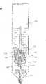
图1示出一设计为标记笔的书写工具。例如,该书写工具能够是一漆标记笔。书写工具具有一包含墨水12的容器10。容器10并不一定构成笔身。相反能够想象的是,设置一笔身,在其中设置容器10。容器10在示出实施例中由一底板14限制,而容器10的外壁延伸通过底板14直至笔尖。FIG. 1 shows a writing implement designed as a marker. For example, the writing implement can be a paint marker. The writing instrument has a
底板14具有一偏心设置的空气出口16,一空气管道18安装到该空气出口上。空气管道18在一第一段中与容器的纵向轴线平行地延伸。在其开口20区域内,空气管道18折弯,并在容器10的容积中心处终止。在此,容积中心在此为那个在少于充满的容器一半时始终空余的点,它不会在任何容器位置被液体覆盖。例如,在一汽缸上,容积中心为汽缸的中心,使得一少于一半的填充的汽缸在任何位置都不覆盖容积中心。The
此外,底板14具有一居中的出口22,它通入到一液体通道。液体通道24作为容器和笔尖之间的连接路径在示出的实施例中居中地延伸通过书写工具。一流量限制器26直接与底板14相连。流量限制器26如此地将流出通道缩小为一横截面,使得行程与正常书写流相应的书写液体流。流量限制器按照一类笔尖的节流阀形式设置,限制来自容器的书写液体的容积流。用于流量的其他规定的尺寸是同样与希望的流量相应的毛细管的长度。Furthermore, the
与流量限制器26相连设置一阀28,它在其封闭位置上阻止书写液体的流动。阀28设计为具有阀元件和阀座的阀,其中阀元件与标记尖端30相连。标记尖端30使阀元件从阀座上移动,释放书写液体从流量限制器流入到笔尖30中的流动。此外,阀设置有弹性的回复元件(未示出),它们向阀元件和由此向笔尖施加一回复的力。Connected to the
笔尖30在其远端由壳体32中凸出。在笔尖30位于内部的端部上设置一补偿存储器34,它容纳多余的书写液体。用于完全控制阀的必要的行程h优选为0.2mm或者更小。为此所需的力为0.2N。
图2示出一按本发明的书写工具的一第二实施方式的横截面。一壁36包围限制容器38,在容器中设有书写液体40。容器38底部由一底部元件42限定,它具有一居中的排气口44。排气口44位于一排气通道46中,它由一排气管48限制。排气管48居中伸入到容器中38中,并在其自由的端部上具有一开口50,它将容器内部空间38与空气通道46相连。在底板42下方,排气通道44弯曲地延伸,并导入笔尖区域内,在那里设置一用于与外界连接的环状间隙52。该环状间隙52由书写工具的笔尖54和相关壁段56之间的空腔构成。通过空气通道46容器内部空间38与外界相连,这实现压力平衡。FIG. 2 shows a cross section through a second embodiment of a writing instrument according to the invention. A
底部元件42具有一第二开口58,它将用于书写液体40的容器38与一前室60相连。前室60具有一流出口61,它在一保持元件62中形成。一设计为细管的流量限制器64与流出口61相连,通过它,书写液体40由前室60导出。流量限制器64限制流量,它流过一开口的较小的横截面和细管的长度。The
在流量限制器下游,设置具有阀元件66和环状阀座68的阀。阀元件66在其背向阀一侧具有凹处67,它们允许书写液体在阀打开时流动。一螺旋弹簧70围绕流量限制器64设置并支承在底部元件42上。Downstream of the flow restrictor, a valve with a
阀座68设计为一环绕的凸起,它在一单独的组件72上构成。用于阀座68的组件72插入一突出部分74居中的凹处中,其中该突出部分能够与底板42设计为整体。The
标记尖端54与设计为阀推杆的阀元件66相连。围绕标记尖端54设置一毛细的补偿存储器76。The marking
标记尖端54居中从书写工具的尖部凸起。一些达到排气通道46的书写液体在壁56的区域内通过标记尖端的毛细存储器供给,使得外流有效地被阻止。A marking
图3示出流量限制器一可选择的设计。这里设置一底部元件78,其中构成一螺旋形流出管道80。流出管道80在元件78中沿外侧延伸,使得它向外部从用于元件78的容纳开口的内壁82限制。一弹簧84在示出的位置上压住阀推杆86并将笔尖压到关闭位置。阀推杆86设有凹处87,并即使在阀推杆回推时也允许书写液体的通流。Figure 3 shows an alternative design of the flow restrictor. A
图4示出阀一可选择的设计,其中阀元件由一滚珠88构成。滚珠88位于一尖端90中,它具有一用于滚珠88的居中的导向通道92。通过对导向通道在自由的端部中横截面的收缩,滚珠88被保持在其中。一螺旋弹簧94将滚珠压到其关闭位置。滚珠88在导向通道92中的运动在相对的方向上由一止挡96限制。在滚珠封闭位置上的滚珠88和止挡96之间的距离限定滚珠的最大行程。通过一芯98,将书写液体供给滚珠。FIG. 4 shows an alternative design of the valve in which the valve element is formed by a
图5示出另一实施例,其中阀和流量限制器的顺序互换。一弹簧100位置固定地设置在容器103的底板101中。弹簧100紧贴于一阀推杆102,它与一阀座104一起密封地发挥作用。背向阀座的一侧设有凹处103,它使用于书写液体的连接路径保持空余。阀座104同样固定地相对于底板元件101设置,并具有一环状凸缘105。通过一波纹管108流量限制器110可推移地保持在位置固定的阀座中。其中,波纹管108密封伸入流量限制器中的通道,因为墨水在波纹管中聚集并从那里进入流量限制器。流量限制器110具有一通流通道112,它确定书写液体流出的大小。标记尖端114直接安装在流量限制器110的通流通道112上。Figure 5 shows another embodiment where the order of the valves and flow restrictors is reversed. A
波纹管108以其端部分别设置在阀座104和流量限制器110的一环绕的槽内。波纹管108的端部优选地夹紧地设置在槽内。The bellows 108 is arranged with its ends in a circumferential groove of the valve seat 104 and the
图6示出按本发明的书写工具的另一设计的横截面。书写工具具有一液体容器112,它被书写液体114填充少于一半。一空气管道116居中地伸入到容器112中,它通过一排气通道118与外界相连。在此,空气管道116从下方端部伸入到容器112中。排气通道118通过一环状缝隙120与外界相连。环状缝隙向外部由一环状外壳部分122限制。环状缝隙120向内部由一纤维尖端124限定。在此,特别的优点在于,一些进入空气管道和排气通道118的书写液体在流出时能够通过排气缝隙由标记尖端120吸收。由此避免墨水不必要的流出。FIG. 6 shows a cross section through a further embodiment of the writing instrument according to the invention. The writing instrument has a
书写液体114通过开口126进入通道形的流量限制器128。流量限制器128具有一长度和一直径,它们如此选择,使得书写液体的流量与笔尖上希望的书写流量相应。流量限制器128延伸至一环状的阀空间130内。阀空间130由一有弹性的阀板132密封。阀板132具有一居中的固定段134,在其中插入纤维尖端124。有弹性的阀板132和一凸缘136共同作用。凸缘设计为环状地围绕一导向通道138在阀板140上。导向通道138同时用来导引纤维尖端124。在打开位置上,即在一向内的力作用到纤维针124的位置上,使阀板132弯回,凸缘136和板132之间形成一环状缝隙。Writing
除了由凸缘唇136和弹性的阀板132的共同作用的流量限制外,如上所述,流量限制同样通过通道段128进行。如图6所示,流出通道的直径如此减小,使得实现流量限制。In addition to the flow limitation by the cooperation of the
Claims (16)
Translated fromChineseApplications Claiming Priority (2)
| Application Number | Priority Date | Filing Date | Title |
|---|---|---|---|
| DE102005022462.8 | 2005-05-14 | ||
| DE102005022462ADE102005022462B4 (en) | 2005-05-14 | 2005-05-14 | writing implement |
Publications (2)
| Publication Number | Publication Date |
|---|---|
| CN101160217Atrue CN101160217A (en) | 2008-04-09 |
| CN100513202C CN100513202C (en) | 2009-07-15 |
Family
ID=37198620
Family Applications (1)
| Application Number | Title | Priority Date | Filing Date |
|---|---|---|---|
| CNB2006800127646AExpired - Fee RelatedCN100513202C (en) | 2005-05-14 | 2006-05-10 | Writing implement for painting, graph plotting and marking |
Country Status (10)
| Country | Link |
|---|---|
| US (1) | US7648297B2 (en) |
| EP (1) | EP1896267B1 (en) |
| JP (1) | JP4871354B2 (en) |
| CN (1) | CN100513202C (en) |
| AT (1) | ATE409600T1 (en) |
| DE (2) | DE102005022462B4 (en) |
| DK (1) | DK1896267T3 (en) |
| ES (1) | ES2316078T3 (en) |
| PL (1) | PL1896267T3 (en) |
| WO (1) | WO2006122693A2 (en) |
Cited By (2)
| Publication number | Priority date | Publication date | Assignee | Title |
|---|---|---|---|---|
| CN111376628A (en)* | 2018-12-28 | 2020-07-07 | 北京文海阳工贸有限责任公司 | Ventilation liquid limiting device and writing pen |
| CN112721495A (en)* | 2021-01-20 | 2021-04-30 | 成都理工大学 | Novel disposable environmental protection refill |
Families Citing this family (4)
| Publication number | Priority date | Publication date | Assignee | Title |
|---|---|---|---|---|
| DE102009053291B4 (en)* | 2009-11-13 | 2015-11-05 | Edding Ag | Paint pen and cap for a paint pen |
| JP2011148203A (en)* | 2010-01-22 | 2011-08-04 | Brother Industries Ltd | Ink cartridge |
| JP5687529B2 (en)* | 2010-03-26 | 2015-03-18 | 株式会社サクラクレパス | Applicator |
| JP6917660B2 (en)* | 2019-03-14 | 2021-08-11 | 株式会社3S | Painter |
Family Cites Families (17)
| Publication number | Priority date | Publication date | Assignee | Title |
|---|---|---|---|---|
| US2624902A (en)* | 1949-03-09 | 1953-01-13 | Jack O Soldner | Fountain marking device with work operable valve |
| US3459484A (en)* | 1967-05-01 | 1969-08-05 | Paul S Abrams | Marking device |
| US3741668A (en)* | 1971-09-30 | 1973-06-26 | Koh I Noor Radiograph Inc | Method of venting a stylographic pen |
| JPS62160297A (en)* | 1986-01-09 | 1987-07-16 | 三菱鉛筆株式会社 | Liquid applicator |
| DE4015586C3 (en)* | 1990-05-15 | 1997-12-04 | Dataprint Datendrucksysteme R | Device for applying writing, drawing, printing or painting fluid on a surface |
| GB9120517D0 (en)* | 1991-09-26 | 1991-11-06 | Gillette Co | Marking instruments |
| CN1163589A (en)* | 1994-11-14 | 1997-10-29 | 吉莱特公司 | Marking instrument |
| GB9422906D0 (en)* | 1994-11-14 | 1995-01-04 | Gillette Co | Writing/marking instrument |
| GB9525695D0 (en)* | 1995-12-15 | 1996-02-14 | Gillette Co | Marking instruments |
| CN2353550Y (en)* | 1998-08-20 | 1999-12-15 | 郭荣平 | Liquid-ink marking pen |
| JP4180183B2 (en)* | 1999-03-31 | 2008-11-12 | パイロットインキ株式会社 | Liquid writing instrument |
| CN2377093Y (en)* | 1999-06-08 | 2000-05-10 | 戎星淼 | Mark pen |
| CN2403581Y (en)* | 2000-01-24 | 2000-11-01 | 太原市奥洁文教用品厂 | Blackboard-writing pen with inner container |
| US6675650B1 (en)* | 2001-11-12 | 2004-01-13 | Yazaki North America | Automotive display |
| JP2004098462A (en)* | 2002-09-09 | 2004-04-02 | Pilot Ink Co Ltd | Liquid direct charging type writing utensil |
| US6575650B1 (en)* | 2002-11-26 | 2003-06-10 | Pro Eton Corporation | Pressure sensed ink-filled pen |
| CN1465485A (en)* | 2002-12-03 | 2004-01-07 | 毛志华 | Universal scheme for writing end adjustable running water and various ink pens thereof |
- 2005
- 2005-05-14DEDE102005022462Apatent/DE102005022462B4/ennot_activeExpired - Fee Related
- 2006
- 2006-05-10ATAT06753550Tpatent/ATE409600T1/enactive
- 2006-05-10ESES06753550Tpatent/ES2316078T3/enactiveActive
- 2006-05-10EPEP06753550Apatent/EP1896267B1/ennot_activeNot-in-force
- 2006-05-10USUS11/913,088patent/US7648297B2/ennot_activeExpired - Fee Related
- 2006-05-10PLPL06753550Tpatent/PL1896267T3/enunknown
- 2006-05-10JPJP2008510494Apatent/JP4871354B2/ennot_activeExpired - Fee Related
- 2006-05-10CNCNB2006800127646Apatent/CN100513202C/ennot_activeExpired - Fee Related
- 2006-05-10DEDE502006001704Tpatent/DE502006001704D1/enactiveActive
- 2006-05-10WOPCT/EP2006/004393patent/WO2006122693A2/enactiveIP Right Grant
- 2006-05-10DKDK06753550Tpatent/DK1896267T3/enactive
Cited By (3)
| Publication number | Priority date | Publication date | Assignee | Title |
|---|---|---|---|---|
| CN111376628A (en)* | 2018-12-28 | 2020-07-07 | 北京文海阳工贸有限责任公司 | Ventilation liquid limiting device and writing pen |
| CN112721495A (en)* | 2021-01-20 | 2021-04-30 | 成都理工大学 | Novel disposable environmental protection refill |
| CN112721495B (en)* | 2021-01-20 | 2024-04-16 | 成都理工大学 | Novel disposable environment-friendly pen refill |
Also Published As
| Publication number | Publication date |
|---|---|
| WO2006122693A2 (en) | 2006-11-23 |
| PL1896267T3 (en) | 2009-04-30 |
| DE102005022462A1 (en) | 2006-12-14 |
| EP1896267B1 (en) | 2008-10-01 |
| CN100513202C (en) | 2009-07-15 |
| DK1896267T3 (en) | 2009-02-02 |
| ATE409600T1 (en) | 2008-10-15 |
| HK1119421A1 (en) | 2009-03-06 |
| ES2316078T3 (en) | 2009-04-01 |
| EP1896267A2 (en) | 2008-03-12 |
| JP4871354B2 (en) | 2012-02-08 |
| WO2006122693A3 (en) | 2007-03-08 |
| US20080193199A1 (en) | 2008-08-14 |
| US7648297B2 (en) | 2010-01-19 |
| DE502006001704D1 (en) | 2008-11-13 |
| JP2008540178A (en) | 2008-11-20 |
| DE102005022462B4 (en) | 2011-08-18 |
Similar Documents
| Publication | Publication Date | Title |
|---|---|---|
| CN101160217A (en) | Writing instruments for painting, drawing and marking | |
| US6183155B1 (en) | Device for applying liquids onto a base using an applicator element | |
| US6164858A (en) | Fluid regulator for supplying a consumer element with fluid from a fluid reservoir | |
| US7467907B2 (en) | Valve mechanisms for paint or ink brush with integrated reservoir | |
| US5518331A (en) | Refillable ink pen | |
| EP3162586B1 (en) | Fountain pen and clean ink refill system | |
| US6648539B2 (en) | Free ink writing instrument with nano technology | |
| US5888007A (en) | Marking instrument | |
| EP0605476A1 (en) | Marking instruments | |
| US5735624A (en) | Relating to writing instruments | |
| JP2010531750A (en) | Writing, marking and / or drawing instruments | |
| HK1119421B (en) | Writing implement for painting, drawing and marking | |
| JP5830849B2 (en) | Writing instrument | |
| US9381767B2 (en) | Device for storing and applying a fluid product | |
| JP4919756B2 (en) | Writing instrument | |
| JP2021007421A (en) | Applicator | |
| EP3162587B1 (en) | Fountain pen | |
| JP7469907B2 (en) | Applicator | |
| WO1996014998A1 (en) | Marking instrument | |
| JP2008265147A (en) | Writing utensil | |
| JP3924933B2 (en) | Writing instrument | |
| JP2005225086A (en) | Liquid applicator | |
| JP2007030375A (en) | Ballpoint pen | |
| JPH1178349A (en) | Writing utensil | |
| JP2006187892A (en) | Liquid applicator |
Legal Events
| Date | Code | Title | Description |
|---|---|---|---|
| C06 | Publication | ||
| PB01 | Publication | ||
| C10 | Entry into substantive examination | ||
| SE01 | Entry into force of request for substantive examination | ||
| REG | Reference to a national code | Ref country code:HK Ref legal event code:DE Ref document number:1119421 Country of ref document:HK | |
| C14 | Grant of patent or utility model | ||
| GR01 | Patent grant | ||
| REG | Reference to a national code | Ref country code:HK Ref legal event code:GR Ref document number:1119421 Country of ref document:HK | |
| CF01 | Termination of patent right due to non-payment of annual fee | Granted publication date:20090715 Termination date:20210510 | |
| CF01 | Termination of patent right due to non-payment of annual fee |