CN101158645B - Rotary Multi-channel Excitation Fluorescence Method Based on Input-Output Optical Fiber - Google Patents
Rotary Multi-channel Excitation Fluorescence Method Based on Input-Output Optical FiberDownload PDFInfo
- Publication number
- CN101158645B CN101158645BCN2007101774654ACN200710177465ACN101158645BCN 101158645 BCN101158645 BCN 101158645BCN 2007101774654 ACN2007101774654 ACN 2007101774654ACN 200710177465 ACN200710177465 ACN 200710177465ACN 101158645 BCN101158645 BCN 101158645B
- Authority
- CN
- China
- Prior art keywords
- optical fiber
- fluorescence
- light
- channel
- output optical
- Prior art date
- Legal status (The legal status is an assumption and is not a legal conclusion. Google has not performed a legal analysis and makes no representation as to the accuracy of the status listed.)
- Expired - Fee Related
Links
- 239000013307optical fiberSubstances0.000titleclaimsabstractdescription69
- 230000005284excitationEffects0.000titleclaimsabstractdescription15
- 238000002795fluorescence methodMethods0.000title1
- 238000001514detection methodMethods0.000claimsabstractdescription28
- 230000008878couplingEffects0.000claimsabstractdescription24
- 238000010168coupling processMethods0.000claimsabstractdescription24
- 238000005859coupling reactionMethods0.000claimsabstractdescription24
- 238000000034methodMethods0.000claimsabstractdescription6
- 238000006243chemical reactionMethods0.000claimsdescription13
- 230000003321amplificationEffects0.000claimsdescription4
- 238000001914filtrationMethods0.000claimsdescription4
- 238000003199nucleic acid amplification methodMethods0.000claimsdescription4
- 230000033001locomotionEffects0.000description9
- 239000000523sampleSubstances0.000description8
- 238000001917fluorescence detectionMethods0.000description5
- 239000000835fiberSubstances0.000description3
- 230000003287optical effectEffects0.000description3
- 241001465754MetazoaSpecies0.000description2
- 238000010586diagramMethods0.000description2
- 239000011159matrix materialSubstances0.000description2
- 238000005259measurementMethods0.000description2
- 239000012472biological sampleSubstances0.000description1
- 230000005540biological transmissionEffects0.000description1
- 238000005516engineering processMethods0.000description1
- 229910052736halogenInorganic materials0.000description1
- 150000002367halogensChemical class0.000description1
- 230000002285radioactive effectEffects0.000description1
- 238000011897real-time detectionMethods0.000description1
- 230000035945sensitivityEffects0.000description1
Images

Landscapes
- Investigating, Analyzing Materials By Fluorescence Or Luminescence (AREA)
Abstract
Translated fromChinese
Description
Translated fromChinese技术领域technical field
本发明为一种基于输入输出光纤的旋转式多通道激发荧光装置和方法,属于生物医学中的光电检测技术领域。The invention relates to a rotary multi-channel excitation fluorescence device and method based on input and output optical fibers, and belongs to the technical field of photoelectric detection in biomedicine.
背景技术Background technique
由于外部光源激发待检测对象诱导出来荧光的检测方式,对于生物、动物和人体的影响非常小,更重要的是荧光检测的动态范围和灵敏度越来越高接近或者赶上放射性检测,因此荧光检测被广泛应用于生命科学、医学研究和实际应用之中,尤其是生物、动物和人体等的活体实时检测领域。Because the external light source stimulates the object to be detected to induce fluorescence detection, it has very little impact on organisms, animals and human bodies. More importantly, the dynamic range and sensitivity of fluorescence detection are getting higher and higher, approaching or catching up with radioactive detection, so fluorescence detection It is widely used in life sciences, medical research and practical applications, especially in the field of real-time detection of living organisms, animals and human bodies.
经典的多通道激发诱导荧光装置和方法,利用一根输入光纤和另一根输出光纤来传输光线,即利用一根输入光纤,将光源的光传输照射反应池,激发生物样品诱导出来荧光,再将诱导出来荧光通过另一根输出光纤输出投射到光电探测器,进行检测。对于二维矩阵式多通道检测,在一个平面上沿着X和Y方向二维移动输入光纤与输出光纤扫描每一个通道完成多通道检测。In the classic multi-channel excitation-induced fluorescence device and method, one input optical fiber and another output optical fiber are used to transmit light, that is, one input optical fiber is used to irradiate the light transmission of the light source to the reaction cell to excite the biological sample to induce fluorescence, and then The induced fluorescence is projected to the photodetector through another output optical fiber for detection. For two-dimensional matrix multi-channel detection, move the input fiber and output fiber two-dimensionally along the X and Y directions on a plane to scan each channel to complete the multi-channel detection.
上述装置中,利用光纤的柔韧性移动光纤进行检测,对于二维矩阵式多通道检测,移动光纤进行X和Y二维运动,因此速度慢、定位及重复定位精度差。速度慢,导致各个通道反应在时间上存在差别;定位精度差,各个通道的光照强度有差值,导致各个通道测量之间不精确;重复定位精度差,导致单个通道的重复测量精度有差别。In the above device, the flexibility of the optical fiber is used to move the optical fiber for detection. For the two-dimensional matrix multi-channel detection, the moving optical fiber performs X and Y two-dimensional movements, so the speed is slow and the positioning and repeat positioning accuracy is poor. The slow speed leads to time differences in the responses of each channel; the poor positioning accuracy and the difference in the light intensity of each channel lead to inaccurate measurements between each channel; the poor repeat positioning accuracy leads to differences in the repeated measurement accuracy of a single channel.
发明内容Contents of the invention
本发明的目的在于提供一种基于输入输出光纤的旋转式多通道激发荧光装置,改进现有光学系统,即利用一组多路光纤作为输入通道将外部激发光引入照射样品,同时又利用另一组多路光纤做输出光路传输诱导出来的荧光。驱动一个电机带动圆盘旋转,通过旋转圆盘让每路输出光纤中的传输光依次经过圆盘上的开孔,投射到光电探测器,实现多通道检测。这样将X和Y方向的二维平面运动由一个旋转运动代替,避免了光学系统的二维移动,该装置具有机电结构简单、速度快的优点,同时克服定位及重复定位精度差难题,具有检测精度高的优点。The purpose of the present invention is to provide a rotary multi-channel excitation fluorescence device based on input and output optical fibers, which improves the existing optical system, that is, uses a group of multi-channel optical fibers as input channels to introduce external excitation light into the irradiated sample, and at the same time uses another A group of multi-channel optical fibers is used as the output optical path to transmit the induced fluorescence. Drive a motor to drive the disk to rotate, and through the rotation of the disk, the transmitted light in each output optical fiber passes through the openings on the disk in turn, and is projected to the photodetector to realize multi-channel detection. In this way, the two-dimensional plane movement in the X and Y directions is replaced by a rotational movement, which avoids the two-dimensional movement of the optical system. The advantage of high precision.
一种基于输入输出光纤的旋转式多通道激发荧光装置,依次包括光源、入射耦合透镜、输入光纤、输出光纤、输出耦合透镜,其特征在于:A rotary multi-channel excitation fluorescence device based on input and output optical fibers, which sequentially includes a light source, an incident coupling lens, an input optical fiber, an output optical fiber, and an output coupling lens, and is characterized in that:
输入光纤为一组多路光纤,输出光纤为一组多路光纤;所述的输出光纤中传输出来的荧光通过输出耦合透镜变成平行光,经过释放光滤镜滤波(Emission Filter)或者分光装置分光的窄带荧光全部投射到一个可旋转的圆盘,驱动电机带动圆盘旋转;在荧光投射到圆盘处开一个孔,投射荧光通过该孔后,垂直入射到光电探测器,光电探测器连接计算机,完成一个通道的探测;驱动圆盘旋转使每路输出光纤中传输的荧光依次通过开孔(通道选通)进行探测,实现多通道检测。The input optical fiber is a group of multi-channel optical fibers, and the output optical fiber is a group of multi-channel optical fibers; the fluorescence transmitted in the output optical fiber becomes parallel light through the output coupling lens, and is filtered by an emission filter (Emission Filter) or a spectroscopic device The narrow-band fluorescent light that is split is all projected onto a rotatable disc, and the drive motor drives the disc to rotate; a hole is opened where the fluorescent light is projected onto the disc, and after the projected fluorescent light passes through the hole, it is vertically incident on the photodetector, and the photodetector is connected to the The computer completes the detection of one channel; the disk is driven to rotate so that the fluorescence transmitted in each output optical fiber passes through the openings (channel gating) in turn for detection, realizing multi-channel detection.
在光源、入射耦合透镜之间还可以设置激发光滤镜(Excitation Filter)或者分光器,一般用于发光二级管LED和卤素灯等宽光谱的光源,将光源发出的光滤波或者分光成为单色光,具有探测背景噪声小的优点。An excitation filter (Excitation Filter) or a beam splitter can also be set between the light source and the incident coupling lens. It is generally used for light-emitting diodes (LEDs) and halogen lamps and other broad-spectrum light sources to filter or split the light emitted by the light source into a single Chromatic light has the advantage of detecting less background noise.
应用上述基于输入输出光纤的旋转式多通道激发荧光装置的方法,包括以下步骤:The method for applying the above-mentioned rotary multi-channel excitation fluorescence device based on input and output optical fibers includes the following steps:
1、打开光源1预热,直到发光稳定;1. Turn on the
2、光源1发出的光经过入射耦合透镜3会聚,耦合进入一组多路输入光纤4中、从输入光纤4出来后照射反应池中样品5,激发样品5发出荧光;2. The light emitted by the
3、激发样品出来的荧光耦合进入一组多路输出光纤6中,从输出光纤6出来的荧光通过输出耦合透镜7变成平行光,经过释放光滤镜滤波或者分光装置8分光的窄带荧光全部投射到一个可旋转的圆盘,驱动电机带动圆盘旋转;在荧光投射到圆盘处开一个孔,投射荧光通过该孔后,垂直入射到光电探测器9,光电探测器9进行光电转换、放大、滤波与模数转化,转化后的数字信号进入计算机10中显示与处理,完成一个通道的探测;驱动圆盘旋转使每路输出光纤中传输的荧光依次通过开孔(通道选通)进行探测,实现多通道检测。3. The fluorescence from the excited sample is coupled into a group of multiple output
本发明的优点在于:驱动电机带动圆盘旋转,使每路输出光纤中传输的荧光依次通过圆盘上的开孔,投射到光电探测器,实现多通道检测。这样将X和Y方向的二维平面运动由一个旋转运动代替,该装置具有机电结构简单、速度快的优点,同时克服定位及重复定位精度差难题,具有检测精度高的优点。The advantage of the present invention is that: the drive motor drives the disk to rotate, so that the fluorescence transmitted in each output optical fiber passes through the openings on the disk in turn, and is projected onto the photoelectric detector to realize multi-channel detection. In this way, the two-dimensional plane motion in the X and Y directions is replaced by a rotary motion. The device has the advantages of simple electromechanical structure and fast speed, and at the same time overcomes the problem of poor positioning and repeat positioning accuracy, and has the advantage of high detection accuracy.
附图说明Description of drawings
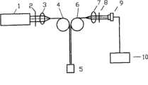
图1为本发明的单通道检测装置结构原理图;Fig. 1 is a schematic structural diagram of a single-channel detection device of the present invention;
图2为本发明基于输入输出光纤的旋转式96通道激发荧光装置的示意图;2 is a schematic diagram of a rotary 96-channel excitation fluorescence device based on input and output optical fibers of the present invention;
具体实施方式:Detailed ways:
下面结合附图,详细对本发明进行说明。The present invention will be described in detail below in conjunction with the accompanying drawings.
实施例:Example:
对于如图1所示的单通道检测装置,光源1发出的光经过激发光滤镜2变成单色光,再经过入射耦合透镜3会聚,耦合进入一组多路输入光纤4里的一根光纤中、单色光从输入光纤4出来后照射反应池中样品5,激发样品5发出荧光;激发出来的荧光直接耦合进入一组多路输出光纤6里的一根光纤中,从输出光纤6出来的荧光通过输出耦合透镜7变成平行光,经过释放光滤镜8滤波的窄带荧光全部投射到一个可旋转的圆盘,驱动电机带动圆盘旋转;在荧光投射到圆盘处开一个孔,投射荧光通过该孔后,垂直入射到光电探测器9,光电探测器9进行光电转换、放大、滤波与模数转化,转化后的数字信号进入计算机10中显示与处理,完成一个通道的探测。For the single-channel detection device shown in Figure 1, the light emitted by the
对于如图2所示的基于输入输出光纤的旋转式96通道激发荧光装置,光源1发出的光,经过激发光滤镜或者分光器2变成单色光,再经过入射耦合透镜3会聚,耦合进入一组多路输入光纤4中、单色光从输入光纤4出来后照射反应池中样品5,激发样品5发出荧光,激发出来的荧光直接耦合进入一组多路输出光纤6中,输出光纤6的输出端放置在一个圆周上;从输出光纤6出来的荧光通过输出耦合透镜7变成平行光,经过释放光滤镜8滤波的窄带荧光全部投射到一个可旋转的圆盘,驱动电机带动圆盘旋转;在荧光投射到圆盘处开一个孔,投射荧光通过该孔后,垂直入射到与旋转圆盘固定连接的光电探测器9,光电探测器9进行光电转换、放大、滤波与模数转化,转化后的数字信号进入计算机10中显示与处理,完成一个通道的探测;驱动圆盘旋转使每路输出光纤中传输的荧光依次通过开孔(通道选通)进行探测,实现多通道检测(为了突出重点图中一些器件没有标明)。For the rotary 96-channel excitation fluorescence device based on the input and output optical fibers shown in Figure 2, the light emitted by the
入射耦合透镜3为每路输入光纤4之前设有一个透镜,透镜可以是普通的分离透镜;透镜可以是制作在每路输入光纤4端面上。The incoupling
输出耦合透镜7可以为一个或者每路输出光纤6之前设有一个透镜。设有一个输出耦合透镜时,每路输出光纤6放置在该透镜的前焦平面上。每路输出光纤6之前设有一个输出耦合透镜时,每路输出光纤6放置在每个输出耦合透镜的前焦平面上,透镜可以是普通的分离透镜;透镜可以是制作在每路输出光纤6前焦平面上。There can be one
一般来讲利用X和Y方向的二维平面运动,一次96孔荧光检测时间在3秒钟,而由一个旋转运动代替X和Y方向的二维平面运动,现有技术非常容易控制转速1000转/秒的电机带动圆盘运动,一次96孔荧光检测时间在0.001秒钟。Generally speaking, using the two-dimensional plane movement in the X and Y directions, the time for a 96-well fluorescence detection is 3 seconds, and the two-dimensional plane movement in the X and Y directions is replaced by a rotational movement. The existing technology is very easy to control the speed of 1000 rpm The motor drives the disc to move per second, and the time for a 96-hole fluorescence detection is 0.001 second.
Claims (1)
Translated fromChinesePriority Applications (1)
| Application Number | Priority Date | Filing Date | Title |
|---|---|---|---|
| CN2007101774654ACN101158645B (en) | 2007-11-16 | 2007-11-16 | Rotary Multi-channel Excitation Fluorescence Method Based on Input-Output Optical Fiber |
Applications Claiming Priority (1)
| Application Number | Priority Date | Filing Date | Title |
|---|---|---|---|
| CN2007101774654ACN101158645B (en) | 2007-11-16 | 2007-11-16 | Rotary Multi-channel Excitation Fluorescence Method Based on Input-Output Optical Fiber |
Publications (2)
| Publication Number | Publication Date |
|---|---|
| CN101158645A CN101158645A (en) | 2008-04-09 |
| CN101158645Btrue CN101158645B (en) | 2010-06-09 |
Family
ID=39306806
Family Applications (1)
| Application Number | Title | Priority Date | Filing Date |
|---|---|---|---|
| CN2007101774654AExpired - Fee RelatedCN101158645B (en) | 2007-11-16 | 2007-11-16 | Rotary Multi-channel Excitation Fluorescence Method Based on Input-Output Optical Fiber |
Country Status (1)
| Country | Link |
|---|---|
| CN (1) | CN101158645B (en) |
Families Citing this family (9)
| Publication number | Priority date | Publication date | Assignee | Title |
|---|---|---|---|---|
| CN101354152B (en)* | 2008-08-29 | 2010-06-16 | 云南天际旭能新能源科技有限公司 | Solar duplex energy-saving steam heating system |
| US8664585B2 (en)* | 2010-11-15 | 2014-03-04 | Siemens Energy, Inc. | Sensor apparatus for detecting and monitoring a crack propagating through a structure |
| CN104568875B (en)* | 2014-12-22 | 2017-02-22 | 北京工业大学 | Rotary scanning real-time fluorescent quantitative PCR (Polymerase Chain Reaction) detection system |
| CN104614351A (en)* | 2015-01-21 | 2015-05-13 | 南京中科神光科技有限公司 | Rapid and multi-channel real-time fluorescence quantification detection device |
| CN105675574B (en)* | 2016-03-17 | 2018-08-10 | 西安天隆科技有限公司 | More fluorescence channel detecting systems for real-time fluorescence quantitative PCR |
| SG10201609334WA (en)* | 2016-11-08 | 2018-06-28 | Delta Electronics Intl Singapore Pte Ltd | Multi-Channel Fluorescence Detection Device |
| CN107505266B (en)* | 2017-08-14 | 2023-08-25 | 重庆电子工程职业学院 | Semi-automatic optical detection analysis system |
| CN108642158A (en)* | 2018-06-19 | 2018-10-12 | 苏州雅睿生物技术有限公司 | A real-time fluorescence detection system for PCR with multi-channel point detection |
| CN108507626A (en)* | 2018-06-25 | 2018-09-07 | 西安交通大学 | A kind of bearing movable component temperature-speed sync monitoring method based on quantum dot |
Citations (6)
| Publication number | Priority date | Publication date | Assignee | Title |
|---|---|---|---|---|
| CN1311436A (en)* | 2000-03-01 | 2001-09-05 | 上海和泰光电科技有限公司 | Reading of biological chip fluorescent image on rotary platform |
| CN1335527A (en)* | 2001-08-23 | 2002-02-13 | 华中科技大学 | Fast deep scanning and imaging method |
| CN1358999A (en)* | 2002-01-11 | 2002-07-17 | 清华大学 | Automatic focus regulator for laser cofocal scanner |
| EP1087222B1 (en)* | 1999-09-22 | 2005-01-26 | Tosoh Corporation | Scanner-type fluorescence detection apparatus using small-sized excitation light source |
| CN101013136A (en)* | 2007-02-08 | 2007-08-08 | 北京工业大学 | Laser-induction fluorescence co-focusing scan device and method |
| CN201107271Y (en)* | 2007-11-16 | 2008-08-27 | 北京工业大学 | Rotary multi-channel excitation fluorescence device based on input and output optical fibers |
- 2007
- 2007-11-16CNCN2007101774654Apatent/CN101158645B/ennot_activeExpired - Fee Related
Patent Citations (7)
| Publication number | Priority date | Publication date | Assignee | Title |
|---|---|---|---|---|
| EP1087222B1 (en)* | 1999-09-22 | 2005-01-26 | Tosoh Corporation | Scanner-type fluorescence detection apparatus using small-sized excitation light source |
| CN1311436A (en)* | 2000-03-01 | 2001-09-05 | 上海和泰光电科技有限公司 | Reading of biological chip fluorescent image on rotary platform |
| US20010046712A1 (en)* | 2000-03-01 | 2001-11-29 | New Dimiension Research & Instrument, Inc. | Fluorescence imaging of biological media on a rotating stage |
| CN1335527A (en)* | 2001-08-23 | 2002-02-13 | 华中科技大学 | Fast deep scanning and imaging method |
| CN1358999A (en)* | 2002-01-11 | 2002-07-17 | 清华大学 | Automatic focus regulator for laser cofocal scanner |
| CN101013136A (en)* | 2007-02-08 | 2007-08-08 | 北京工业大学 | Laser-induction fluorescence co-focusing scan device and method |
| CN201107271Y (en)* | 2007-11-16 | 2008-08-27 | 北京工业大学 | Rotary multi-channel excitation fluorescence device based on input and output optical fibers |
Non-Patent Citations (2)
| Title |
|---|
| HUANG Guoliang, CHENG Jing et al..Optimum combined lenses for confocal biochip scanningsystem.TSINGHUA SCIENCE AND TECHNOLOGY7 4.2002,7(4),374-378. |
| HUANG Guoliang, CHENG Jing et al..Optimum combined lenses for confocal biochip scanningsystem.TSINGHUA SCIENCE AND TECHNOLOGY7 4.2002,7(4),374-378.* |
Also Published As
| Publication number | Publication date |
|---|---|
| CN101158645A (en) | 2008-04-09 |
Similar Documents
| Publication | Publication Date | Title |
|---|---|---|
| CN101158645B (en) | Rotary Multi-channel Excitation Fluorescence Method Based on Input-Output Optical Fiber | |
| CN101158644B (en) | Method of Inducing Fluorescence in Rotary Multi-channel Based on Transmission Fiber | |
| CN108642158A (en) | A real-time fluorescence detection system for PCR with multi-channel point detection | |
| JP2008534966A5 (en) | ||
| CN204330595U (en) | A kind of real time multi-channel fluorescence detecting system | |
| CN100526883C (en) | Reflection photometer for gold standard immunoassay strips | |
| CN102305778B (en) | Micro-multispectral fluorescence reception and treatment system | |
| WO2016124083A1 (en) | Superminiature multi-channel real-time fluorescence spectrometer | |
| BRPI0609544B8 (en) | detection device, detection system, and method | |
| BRPI0609769B8 (en) | detection device, detection system, and method | |
| CN102389288B (en) | Confocal laser micro-endoscope | |
| CN102243165B (en) | Photonic crystal coded microsphere biochip detection device | |
| CN104677827B (en) | A device and method for subtracting a visible-near-infrared diffuse reflection baseline signal based on a portable fiber optic spectrometer | |
| CN102279174A (en) | Alga identification and measurement sensor and method | |
| ITPI20090147A1 (en) | METHOD OF SPETTRAL IMAGING IN DEPTH AND EQUIPMENT THAT ACTIVATE THIS METHOD | |
| CN204462019U (en) | A kind of subminiaturization hyperchannel real-time fluorescence spectrum detection device | |
| CN201107270Y (en) | Rotary type multichannel inducing fluorescent apparatus based on transmission optical fiber | |
| CN104655599A (en) | Fluorescent test paper, fluorescent excitation device and portable fluorescent analysis system | |
| CN101308093A (en) | Parallel multi-channel optical detection device | |
| CN201107271Y (en) | Rotary multi-channel excitation fluorescence device based on input and output optical fibers | |
| JPH0120371B2 (en) | ||
| Georgel et al. | Silicon photomultiplier—a high dynamic range, high sensitivity sensor for bio-photonics applications | |
| CN202057599U (en) | Micro multispectral fluorescent light receiving and processing system | |
| US20150097124A1 (en) | Shutter assembly for a luminescence-based sample analyzer | |
| CN2938080Y (en) | Reflection photometer of gold-labeled immunity test paper strip |
Legal Events
| Date | Code | Title | Description |
|---|---|---|---|
| C06 | Publication | ||
| PB01 | Publication | ||
| C10 | Entry into substantive examination | ||
| SE01 | Entry into force of request for substantive examination | ||
| C14 | Grant of patent or utility model | ||
| GR01 | Patent grant | ||
| C17 | Cessation of patent right | ||
| CF01 | Termination of patent right due to non-payment of annual fee | Granted publication date:20100609 Termination date:20121116 |