CN101156355A - Detecting Legacy Consumers in Power over Ethernet Systems - Google Patents
Detecting Legacy Consumers in Power over Ethernet SystemsDownload PDFInfo
- Publication number
- CN101156355A CN101156355ACNA2006800093508ACN200680009350ACN101156355ACN 101156355 ACN101156355 ACN 101156355ACN A2006800093508 ACNA2006800093508 ACN A2006800093508ACN 200680009350 ACN200680009350 ACN 200680009350ACN 101156355 ACN101156355 ACN 101156355A
- Authority
- CN
- China
- Prior art keywords
- response
- detection
- value
- signal
- produces
- Prior art date
- Legal status (The legal status is an assumption and is not a legal conclusion. Google has not performed a legal analysis and makes no representation as to the accuracy of the status listed.)
- Granted
Links
- 238000001514detection methodMethods0.000claimsabstractdescription102
- 238000000034methodMethods0.000claimsabstractdescription15
- 239000003990capacitorSubstances0.000description4
- 230000005540biological transmissionEffects0.000description3
- 238000012986modificationMethods0.000description3
- 230000004048modificationEffects0.000description3
- 238000010586diagramMethods0.000description2
- 238000005259measurementMethods0.000description2
- 101100154785Mus musculus Tulp2 geneProteins0.000description1
- 238000000899pressurised-fluid extractionMethods0.000description1
- 238000012358sourcingMethods0.000description1
Images
Classifications
- Y02B70/325—
- Y02B70/3275—
- Y02B90/2638—
- Y02B90/2646—
- Y02B90/2653—
- Y02B90/2669—
- Y04S20/228—
- Y—GENERAL TAGGING OF NEW TECHNOLOGICAL DEVELOPMENTS; GENERAL TAGGING OF CROSS-SECTIONAL TECHNOLOGIES SPANNING OVER SEVERAL SECTIONS OF THE IPC; TECHNICAL SUBJECTS COVERED BY FORMER USPC CROSS-REFERENCE ART COLLECTIONS [XRACs] AND DIGESTS
- Y04—INFORMATION OR COMMUNICATION TECHNOLOGIES HAVING AN IMPACT ON OTHER TECHNOLOGY AREAS
- Y04S—SYSTEMS INTEGRATING TECHNOLOGIES RELATED TO POWER NETWORK OPERATION, COMMUNICATION OR INFORMATION TECHNOLOGIES FOR IMPROVING THE ELECTRICAL POWER GENERATION, TRANSMISSION, DISTRIBUTION, MANAGEMENT OR USAGE, i.e. SMART GRIDS
- Y04S20/00—Management or operation of end-user stationary applications or the last stages of power distribution; Controlling, monitoring or operating thereof
- Y04S20/20—End-user application control systems
- Y04S20/242—Home appliances
- Y04S20/244—Home appliances the home appliances being or involving heating ventilating and air conditioning [HVAC] units
- Y—GENERAL TAGGING OF NEW TECHNOLOGICAL DEVELOPMENTS; GENERAL TAGGING OF CROSS-SECTIONAL TECHNOLOGIES SPANNING OVER SEVERAL SECTIONS OF THE IPC; TECHNICAL SUBJECTS COVERED BY FORMER USPC CROSS-REFERENCE ART COLLECTIONS [XRACs] AND DIGESTS
- Y04—INFORMATION OR COMMUNICATION TECHNOLOGIES HAVING AN IMPACT ON OTHER TECHNOLOGY AREAS
- Y04S—SYSTEMS INTEGRATING TECHNOLOGIES RELATED TO POWER NETWORK OPERATION, COMMUNICATION OR INFORMATION TECHNOLOGIES FOR IMPROVING THE ELECTRICAL POWER GENERATION, TRANSMISSION, DISTRIBUTION, MANAGEMENT OR USAGE, i.e. SMART GRIDS
- Y04S40/00—Systems for electrical power generation, transmission, distribution or end-user application management characterised by the use of communication or information technologies, or communication or information technology specific aspects supporting them
- Y04S40/12—Systems for electrical power generation, transmission, distribution or end-user application management characterised by the use of communication or information technologies, or communication or information technology specific aspects supporting them characterised by data transport means between the monitoring, controlling or managing units and monitored, controlled or operated electrical equipment
- Y04S40/124—Systems for electrical power generation, transmission, distribution or end-user application management characterised by the use of communication or information technologies, or communication or information technology specific aspects supporting them characterised by data transport means between the monitoring, controlling or managing units and monitored, controlled or operated electrical equipment using wired telecommunication networks or data transmission busses
- Y04S40/125—
- Y—GENERAL TAGGING OF NEW TECHNOLOGICAL DEVELOPMENTS; GENERAL TAGGING OF CROSS-SECTIONAL TECHNOLOGIES SPANNING OVER SEVERAL SECTIONS OF THE IPC; TECHNICAL SUBJECTS COVERED BY FORMER USPC CROSS-REFERENCE ART COLLECTIONS [XRACs] AND DIGESTS
- Y04—INFORMATION OR COMMUNICATION TECHNOLOGIES HAVING AN IMPACT ON OTHER TECHNOLOGY AREAS
- Y04S—SYSTEMS INTEGRATING TECHNOLOGIES RELATED TO POWER NETWORK OPERATION, COMMUNICATION OR INFORMATION TECHNOLOGIES FOR IMPROVING THE ELECTRICAL POWER GENERATION, TRANSMISSION, DISTRIBUTION, MANAGEMENT OR USAGE, i.e. SMART GRIDS
- Y04S40/00—Systems for electrical power generation, transmission, distribution or end-user application management characterised by the use of communication or information technologies, or communication or information technology specific aspects supporting them
- Y04S40/12—Systems for electrical power generation, transmission, distribution or end-user application management characterised by the use of communication or information technologies, or communication or information technology specific aspects supporting them characterised by data transport means between the monitoring, controlling or managing units and monitored, controlled or operated electrical equipment
- Y04S40/126—Systems for electrical power generation, transmission, distribution or end-user application management characterised by the use of communication or information technologies, or communication or information technology specific aspects supporting them characterised by data transport means between the monitoring, controlling or managing units and monitored, controlled or operated electrical equipment using wireless data transmission
- Y—GENERAL TAGGING OF NEW TECHNOLOGICAL DEVELOPMENTS; GENERAL TAGGING OF CROSS-SECTIONAL TECHNOLOGIES SPANNING OVER SEVERAL SECTIONS OF THE IPC; TECHNICAL SUBJECTS COVERED BY FORMER USPC CROSS-REFERENCE ART COLLECTIONS [XRACs] AND DIGESTS
- Y04—INFORMATION OR COMMUNICATION TECHNOLOGIES HAVING AN IMPACT ON OTHER TECHNOLOGY AREAS
- Y04S—SYSTEMS INTEGRATING TECHNOLOGIES RELATED TO POWER NETWORK OPERATION, COMMUNICATION OR INFORMATION TECHNOLOGIES FOR IMPROVING THE ELECTRICAL POWER GENERATION, TRANSMISSION, DISTRIBUTION, MANAGEMENT OR USAGE, i.e. SMART GRIDS
- Y04S40/00—Systems for electrical power generation, transmission, distribution or end-user application management characterised by the use of communication or information technologies, or communication or information technology specific aspects supporting them
- Y04S40/12—Systems for electrical power generation, transmission, distribution or end-user application management characterised by the use of communication or information technologies, or communication or information technology specific aspects supporting them characterised by data transport means between the monitoring, controlling or managing units and monitored, controlled or operated electrical equipment
- Y04S40/128—Systems for electrical power generation, transmission, distribution or end-user application management characterised by the use of communication or information technologies, or communication or information technology specific aspects supporting them characterised by data transport means between the monitoring, controlling or managing units and monitored, controlled or operated electrical equipment involving the use of Internet protocol
Landscapes
- Small-Scale Networks (AREA)
- Dc Digital Transmission (AREA)
- Measurement Of Resistance Or Impedance (AREA)
- Power Sources (AREA)
- Emergency Protection Circuit Devices (AREA)
- Measurement Of Current Or Voltage (AREA)
- Mobile Radio Communication Systems (AREA)
- Tests Of Electronic Circuits (AREA)
Abstract
Translated fromChinese
Description
Translated fromChinese本申请要求2005年1月25日提交的名称为“支持高级以太网供电系统的系统和方法(SYSTEM AND METHOD FOR SUPPORTING ADVANCED POWEROVER ETHERNET SYSTEM)”的美国临时专利申请第60/646,509号的优先权。This application claims priority to U.S. Provisional Patent Application No. 60/646,509, filed January 25, 2005, entitled "SYSTEM AND METHOD FOR SUPPORTING ADVANCED POWEROVER ETHERNET SYSTEM," filed January 25, 2005.
技术领域technical field
[0001]本发明涉及一种供电系统,更具体地讲,涉及用于检测以太网供电(PoE)系统中传统用电设备(PD)的电路和方法。[0001] The present invention relates to a power supply system, and more particularly, to a circuit and a method for detecting a traditional powered device (PD) in a Power over Ethernet (PoE) system.
背景技术Background technique
[0002]近年来,以太网已经成为局域网最常用的方法。IEEE802.3组,以太网标准的发起人,已经开发出了该标准的延伸形式,称为IEEE802.3af,定义通过以太网电缆供电。IEEE802.3af标准定义了以太网供电(PoE)系统,涉及通过非屏蔽的双绞线将电力从供电设备(PSE)传输到位于链路相对侧的用电设备(PD)。传统上,网络设备例如IP电话,无线LAN接入点,个人电脑和网络摄像头需要两个连接:一个连接到LAN,而另一个连接到供电系统。PoE系统消除了需要额外的插口和接线,以向网络设备供电。取而代之的是,通过用于数据传输的以太网电缆供电。[0002] In recent years, Ethernet has become the most commonly used method for local area networks. The IEEE802.3 group, the originators of the Ethernet standard, has developed an extension of the standard called IEEE802.3af that defines power over Ethernet cables. The IEEE802.3af standard defines a Power over Ethernet (PoE) system that involves the transmission of power over unshielded twisted-pair wires from a power sourcing equipment (PSE) to a powered device (PD) on the opposite side of the link. Traditionally, network devices such as IP phones, wireless LAN access points, personal computers and network cameras require two connections: one to the LAN and the other to the power supply. PoE systems eliminate the need for additional outlets and wiring to power network devices. Instead, power is supplied via the Ethernet cable used for data transmission.
[0003]如IEEE802.3af标准所定义的,PSE和PD是非数据实体,允许网络设备使用与用于数据传输同类的电缆供电和获取电力。PSE是在物理连接点电连接到电缆的设备,它向链路供电。PSE通常与以太网开关,路由器,集线器或其它网络交换设备或中跨供电设备相连。PD是获得供电或请求供电的设备。PD可与例如数字IP电话,无线网络接入点,PDA或笔记本电脑系泊部位,手机充电器和HVAC恒温器等设备相连。[0003] As defined in the IEEE802.3af standard, PSE and PD are non-data entities, allowing network devices to use the same cable used for data transmission to supply power and obtain power. A PSE is a device electrically connected to the cable at the point of physical connection, which supplies power to the link. PSEs are usually connected to Ethernet switches, routers, hubs or other network switching devices or midspan power supply devices. A PD is a device that gets or requests power. PDs can interface with devices such as digital IP phones, wireless network access points, PDA or laptop docks, cell phone chargers and HVAC thermostats.
[0004]PSE的主要功能是为请求供电的PD搜寻链路,可选地对PD分级,如果探测到PD则向所述链路供电,监控链路上的供电,并且当不再请求和需要时切断电源。PD通过呈现由IEEE802.3af标准所定义的PoE检测信号来参与PD检测程序。PD检测信号具有由PSE测量的电学特征,例如在19-26.5KΩ范围内的信号电阻。[0004] The main function of the PSE is to search for a link for a PD requesting power supply, optionally classify the PD, supply power to the link if a PD is detected, monitor the power supply on the link, and when no longer request and need cut off the power. A PD participates in the PD detection procedure by presenting a PoE detection signal defined by the IEEE802.3af standard. The PD detection signal has an electrical characteristic measured by the PSE, such as a signal resistance in the range of 19-26.5KΩ.
[0005]不过,在IEEE802.3af标准批准之前制造的某些PD没有IEEE802.3af标准检测信号。这些PD被称作传统PD。例如,一些传统PD可具有大电容和至少一个串联二极管作为它们的PoE检测信号。其它的传统PD可使用数据回送作为它的PoE检测信号。所述数据回送涉及不直接用于PD检测的线对之间的较小电容。[0005] However, some PDs manufactured before the ratification of the IEEE802.3af standard do not have the IEEE802.3af standard detection signal. These PDs are called legacy PDs. For example, some legacy PDs may have a large capacitor and at least one series diode as their PoE detection signal. Other legacy PDs may use Data Echo as its PoE detection signal. The data loopback involves a small capacitance between wire pairs that are not directly used for PD detection.
[0006]尽管希望向传统的PD供电,但是它们在常规PD检测过程中不会被检测到。因此,需要支持检测传统PD的PD检测方案。[0006] Although it is desirable to provide power to conventional PDs, they are not detected during conventional PD detection. Therefore, there is a need for a PD detection scheme that supports detection of legacy PDs.
发明内容Contents of the invention
[0007]本发明提供了新型的系统和方法,用于检测以太网供电(PoE)系统中的用电设备(PD)。PD探查电路生成提供给PD的检测信号并确定响应所述检测信号而产生的PD响应信号。根据PD响应信号,控制电路确定检测值用于识别PD。具体地讲,控制电路推断如果检测值在第一预定范围,则PD是满足PoE标准的设备,并且推断如果检测值是在第一预定范围之外的第二预定范围,则PD是传统的PD设备。[0007] The present invention provides novel systems and methods for detecting powered devices (PDs) in Power over Ethernet (PoE) systems. The PD detection circuit generates a detection signal provided to the PD and determines a PD response signal generated in response to the detection signal. According to the PD response signal, the control circuit determines a detection value for identifying the PD. Specifically, the control circuit deduces that if the detection value is within a first predetermined range, the PD is a PoE-compliant device, and deduces that if the detection value is within a second predetermined range outside the first predetermined range, the PD is a conventional PD equipment.
[0008]根据本发明的一个方面,所述控制电路可以将检测值和预定阈值作比较,以确定PD是否是传统设备。例如,如果检测值为负或者小于预定阈值,其中所述预定阈值可以小于第一预定范围的最小值,则识别PD为传统设备。[0008] According to an aspect of the present invention, the control circuit can compare the detection value with a predetermined threshold to determine whether the PD is a legacy device. For example, if the detection value is negative or less than a predetermined threshold, where the predetermined threshold may be less than a minimum value in a first predetermined range, then identify the PD as a legacy device.
[0009]根据本发明的实施例,所述检测值可包括检测电阻值。控制电路可以确定PD是传统的PD设备,如果检测电阻值为负或者小于阈值电阻值。所述阈值电阻值可以小于IEEE802.3af标准中定义的信号电阻的最小可接受值。[0009] According to an embodiment of the present invention, the detection value may include a detection resistance value. The control circuit can determine that the PD is a conventional PD device if the detection resistance value is negative or less than the threshold resistance value. The threshold resistance value may be less than the minimum acceptable value of signal resistance defined in the IEEE802.3af standard.
[0010]PD探查电路可以产生第一检测电流,随后是小于第一检测电流的第二检测电流。如果响应第一电流所产生的第一响应电压小于响应第二电流所产生的第二响应电压,则控制电路可检测到传统的PD设备。[0010] The PD detection circuit may generate a first detection current followed by a second detection current that is less than the first detection current. If the first response voltage generated in response to the first current is smaller than the second response voltage generated in response to the second current, the control circuit may detect a conventional PD device.
[0011]另外,如果第一响应电压大于第二响应电压,但这些电压之间的差值小于预设的阈值,则控制电路可检测到传统的PD设备。[0011] In addition, if the first response voltage is greater than the second response voltage, but the difference between these voltages is less than a preset threshold, the control circuit can detect a conventional PD device.
[0012]例如,当由第一响应电压和第二响应电压之间的差值定义的检测电阻值为负或小于预定的阈值电阻值,其可以小于由PoE标准定义的最小信号电阻值,则控制电路可检测到传统设备。[0012] For example, when the detection resistance value defined by the difference between the first response voltage and the second response voltage is negative or less than a predetermined threshold resistance value, which may be less than the minimum signal resistance value defined by the PoE standard, then The control circuit detects legacy equipment.
[0013]根据本发明的方法,执行下述步骤来检测PoE系统中的PD:According to the method of the present invention, carry out following steps to detect the PD in PoE system:
-产生提供给PD的检测信号,以确定PD响应信号,和- generating a detection signal provided to the PD to determine a PD response signal, and
-根据PD响应信号,如果检测值在第一预定范围则确定PD是满足PoE标准的设备,和如果检测值在第一范围之外的第二预定范围则确定PD是传统PD设备。- According to the PD response signal, determining that the PD is a device meeting the PoE standard if the detection value is within a first predetermined range, and determining that the PD is a legacy PD device if the detection value is within a second predetermined range outside the first range.
[0014]产生检测信号的步骤可包括产生第一检测信号,随后是具有比第一检测信号更小值的第二检测信号。当由响应第一检测信号所产生的第一响应信号和响应第二检测信号所产生的第二响应信号之间的差值定义的检测电阻值为负或小于阈值电阻值,则检测到传统设备。[0014] The step of generating the detection signal may include generating a first detection signal followed by a second detection signal having a smaller value than the first detection signal. A legacy device is detected when the detection resistance value defined by the difference between the first response signal generated in response to the first detection signal and the second response signal generated in response to the second detection signal is negative or less than the threshold resistance value .
[0015]对于本领域的技术人员来说,本发明的其他优点和方面将通过下述详细说明而变得显而易见,其中示出和描述了本发明的实施例,只是通过示出实现本发明的最佳模式。如下文所述,本发明可具有其它和不同的实施例,并且它的若干细节可在不背离本发明精神的前提下在各种不同的方面进行改进。因此,附图和说明应当被认为是描述性的,而非限制性的。[0015] For those skilled in the art, other advantages and aspects of the present invention will become apparent from the following detailed description, wherein the embodiments of the present invention are shown and described, only by illustrating the implementation of the present invention best mode. As hereinafter described, the invention is capable of other and different embodiments, and its several details can be modified in various respects, all without departing from the spirit of the invention. Accordingly, the drawings and descriptions should be regarded as descriptive rather than restrictive.
附图说明Description of drawings
[0016]结合下述附图可以最好的理解本发明实施例的下述详细说明,其中特征不必要按照比例绘制,而是以最佳示出相关特征的形式绘制,其中:[0016] The following detailed description of embodiments of the invention is best understood in conjunction with the following drawings, wherein features are not necessarily drawn to scale, but rather are drawn in a form that best illustrates the relevant features, wherein:
图1是示出根据本发明用于检测PD的示例性系统的方框图。FIG. 1 is a block diagram illustrating an exemplary system for detecting PD according to the present invention.
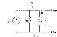
图2是检测源的诺顿(Norton)等效电路。Figure 2 is the Norton equivalent circuit of the detection source.
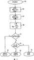
图3是流程图,示出用于控制检测传统PD的系统操作的控制算法。FIG. 3 is a flowchart illustrating a control algorithm for controlling the operation of a system for detecting legacy PDs.
具体实施方式Detailed ways
[0017]本发明将以检测PoE系统中传统PD为例进行说明。不过,显而易见,本文描述的构思可用于识别由供电系统供电的任何可连接设备。[0017] The present invention will be described by taking detection of a traditional PD in a PoE system as an example. It should be apparent, however, that the concepts described herein can be used to identify any connectable device powered by a power supply system.
[0018]图1示出了在PoE系统中的本发明的PD检测系统10的简化方框图,包括PSE12,和通过链路16可连接到PSE12的PD14,所述链路例如是在IEEE802.3af标准中定义的2-线链路。PD检测系统10包括检测源18和控制器20,可安置在PSE12中。Fig. 1 shows a simplified block diagram of the PD detection system 10 of the present invention in a PoE system, including a PSE12, and a PD14 connectable to the PSE12 through a link 16, such as in the IEEE802.3af standard 2-wire link defined in . PD detection system 10 includes a
[0019]检测源18可以是强制电流检测源,它产生提供给PD14的检测电流Idet并且确定响应检测电流所产生的电压Vres。控制器20可以是设置在PSE12中的状态机或微控制器。[0019] The
[0020]图2示出检测源18的诺顿等效电路,它包括电流源22,与电流源22并联连接的源电阻Rsc,和与源电阻Rsc并联连接的电压监控器24。[0020] FIG. 2 shows a Norton equivalent circuit of the
[0021]在检测PD 14的每次测试中,检测源18产生检测电流Idet,它可对应IEEE802.3af标准中定义的电压范围在2.8V-10V的检测电压Vdet。源电阻Rsc的范围在100Kohm-100Mohm。不同检测测试所产生的检测电流Idet的值之间的最小电流差值对应1V的Vdet电压差。[0021] In each test of detecting the PD 14, the
[0022]电压监控器24确定响应提供给PD14的检测电流Idet所产生的电压Vres。PD14的检测电阻Rdet确定为:[0022]
Rdet=ΔVres/ΔIdet,Rdet=ΔVres/ΔIdet,
其中ΔIdet是不同测试中检测电流之间的差值,而ΔVres是响应各自检测电流所产生的电压之间的差值。where ΔIdet is the difference between the sense currents in different tests, and ΔVres is the difference between the voltages generated in response to the respective sense currents.
[0023]图3是流程图,示出了由控制器24执行的控制算法,使得PD检测系统10能够检测传统PD,其中所述传统PD可以是不具有IEEE802.3af标准所要求的检测信号的PD。例如,一些传统PD可具有大电容和至少一个串联二极管作为它们的PoE检测信号。其它传统PD可使用数据回送作为其PoE检测信号。这种数据回送涉及不直接用于PD检测的线对之间的较小电容。[0023] FIG. 3 is a flow chart showing the control algorithm executed by the
[0024]PD检测程序开始(步骤102)之后,控制器20请求检测源18生成检测电流I1。例如,可产生240mA的电流。在预设的等待时间例如等于160ms之后,控制检测源18,以使电压监控器24能够测量响应提供给PD14的电流I1所产生的电压V1(步骤104)。[0024] After the PD detection program starts (step 102), the controller 20 requests the
[0025]此后,控制器20请求检测源18生成小于电流I1的检测电流I2。例如,电流I2可以等于180mA。在预设的等待时间例如等于160ms之后,请求电压监控器24测量响应提供给PD14的电流I2而产生的电压V2(步骤106)。[0025] Thereafter, the controller 20 requests the
[0026]根据测量的响应电压V1和V2,在步骤108控制器20计算PD14的检测电阻Rdet如下:According to the response voltage V of measurement1 and V2 , in
Rdet=(V1-V2)/(I1-I2),Rdet=(V1 -V2 )/(I1 -I2 ),
并确定所计算的检测电阻Rdet是否在IEEE802.3af标准可接受的范围内,例如17KΩ-30KΩ(步骤110)。如果是,控制器20推断PD14是符合IEEE802.3af标准的设备(步骤112)。And determine whether the calculated detection resistance Rdet is within the acceptable range of IEEE802.3af standard, for example, 17KΩ-30KΩ (step 110 ). If yes, controller 20 infers that PD 14 is an IEEE 802.3af compliant device (step 112).
[0027]如果所计算的检测电阻Rdet在IEEE802.3af标准可接受的范围之外,则控制器20确定PD14是可由PSE12供电的传统设备。例如,如果PD14是具有大电容(例如大于47μF)和二极管与该电容串联的传统设备,由于对大电容的充电,第二测量的电压V2会大于电压V1。如果电容非常大,则两个测量的电压V1和V2会具有几乎相同的值。这些电压之间的差值会被限制为由串联二极管两端的正向压降导致的补偿电压。[0027] If the calculated detection resistance Rdet is outside the acceptable range of the IEEE802.3af standard, the controller 20 determines that the PD 14 is a legacy device that can be powered by the PSE 12. For example, if PD 14 is a conventional device with a large capacitance (eg, greater than 47 μF) and a diode in series with the capacitance, the second measured voltage V2 will be greater than voltage V1 due to charging of the large capacitance. If the capacitance is very large, the two measured voltagesV1 andV2 will have almost the same value. The difference between these voltages is limited to the compensation voltage caused by the forward voltage drop across the series diodes.
[0028]如果PD14是具有较小电容(例如在1μF-33μF的范围内)和电阻与该电容并联的传统设备,则根据电容的大小,电阻值,所产生的检测电流I1和I2的值,以及电压V1和V2测量之间的时间段,第二测量的电压V2可能大于或可能不大于电压V1。不过,利用由电容充电时电容和并联电阻的组合所产生的补偿电压所导致的电压V1和V2之间的差值,可以识别所连接的PD14是传统设备。If PD14 is to have the conventional equipment with less capacitance (for example in the range of 1 μ F-33 μ F) and resistance and this capacitance parallel connection, then according to the size of capacitance, resistance value, the detection current I1 and I2 that produce value, and the time period between voltage V1 and V2 measurements, the second measured voltage V2 may or may not be greater than voltage V1 . However, the difference between the voltagesV1 andV2 caused by the compensating voltage generated by the combination of the capacitor and the parallel resistance when the capacitor is charged can identify the connected PD14 as a legacy device.
[0029]因此,如果响应小于第一检测电流I1的第二检测电流I2而产生的第二测量电压V2大于第一测量电压V1,则控制器20可断定所连接的PD14是传统设备。[0029] Therefore, if the second measured voltageV2 generated in response to the second sensed currentI2 , which is less than the first sensed current I1, is greater than the first measured voltageV1 , the controller 20 may conclude that the connected PD 14 is a conventional equipment.
[0030]此外,如果电压V1大于电压V2,控制器20可将这些电压之间的差值与预选的阈值电压作比较,其中所述预选的阈值电压对应响应连续提供的检测电流I1和I2而产生的补偿电压。如果电压V1和V2之间的差小于阈值电压,控制器20可断定所连接的PD14为传统设备。[0030] Additionally, if the voltage V1 is greater than the voltage V2 , the controller 20 may compare the difference between these voltages with a preselected threshold voltage corresponding to the continuously provided detection current I1 and the compensation voltage generated byI2 . If the difference between voltages V1 and V2 is less than the threshold voltage, controller 20 may conclude that connected PD 14 is a legacy device.
[0031]根据本发明的实施例,如果步骤108中计算的检测电阻Rdet在IEEE802.3af标准可接受的范围之外,则控制器20将检测电阻与对应预选阈值电压的阈值电阻Rth作比较,以检测可连接至PSE12的传统用电设备(步骤114)。例如,阈值电阻Rth可等于6KΩ。According to an embodiment of the present invention, if the detection resistance Rdet calculated in
[0032]如果检测电阻Rdet小于阈值电阻Rth,或为负值(表示电压V2大于电压V1),则控制器20断定所连接的PD14是可由PSE12供电的传统设备(步骤116)。如果检测电阻Rdet不是负值或不小于阈值电阻Rth,则控制器20确定所连接的设备既不是符合IEEE802.3af标准的PD,也不是可由PSE12供电的传统PD(步骤118)。[0032] If the detection resistance Rdet is smaller than the threshold resistance Rth, or is negative (representing that the voltage V2 is greater than the voltage V1 ), the controller 20 concludes that the connected PD 14 is a conventional device that can be powered by the PSE 12 (step 116). If the detection resistance Rdet is not negative or less than the threshold resistance Rth, the controller 20 determines that the connected device is neither an IEEE802.3af compliant PD nor a legacy PD that can be powered by the PSE 12 (step 118).
[0033]因此,除IEEE802.3af标准可接受的第一检测电阻范围之外,控制器20检查预选的第二检测电阻范围,以检测可连接到PSE12的传统设备。如上所述,第二检测范围可以覆盖,例如,负值的检测电阻或值,小于预定的阈值电阻。如果所连接的PD14的检测电阻Pdet在第二范围内,所连接的PD14被认为是传统设备。结果,PSE12不仅能够检测符合IEEE802.3af标准的用电设备,还可以检测需要供电的传统设备。[0033] Accordingly, the controller 20 checks a preselected second sense resistor range to detect legacy devices connectable to the PSE 12, in addition to the IEEE 802.3af standard acceptable first sense resistor range. As mentioned above, the second detection range may cover, for example, negative values of the sense resistance or values, which are less than a predetermined threshold resistance. If the detection resistance Pdet of the connected PD 14 is within the second range, the connected PD 14 is considered a legacy device. As a result, the PSE12 is capable of detecting not only powered devices that comply with the IEEE802.3af standard, but also legacy devices that require power.
[0034]前述说明示出和描述了本发明的方面。此外,本发明只示出和描述了优选的实施例,但如前所述,应当理解,本发明能够用于各种其它的组合,改进,和环境,并且可在本文表述的本发明构思范围内进行修改和改进,与上述教导,和/或相关领域的技术或知识范围相当。[0034] The foregoing specification illustrates and describes aspects of the invention. In addition, the present invention only shows and describes the preferred embodiment, but as mentioned above, it should be understood that the present invention can be used in various other combinations, modifications, and environments, and can be used within the scope of the inventive concept expressed herein Modifications and improvements commensurate with the above teachings, and/or within the skill or knowledge of the relevant art.
[0035]上文描述的实施例还进一步用于解释实现本发明的最佳模式,并且可使本领域的技术人员通过以该方式或其它实施方式实现本发明,并根据本发明的特殊应用或用途的需要进行各种修改。The embodiment described above is also further used to explain the best mode of realizing the present invention, and can make those skilled in the art realize the present invention by this mode or other implementation modes, and according to the special application of the present invention or Various modifications are required for the purpose.
[0036]因此,本说明书并非倾向于将本发明限定为本文公开的形式。另外,所附权利要求书应当被理解为包括可替换的实施例。[0036] Accordingly, the description is not intended to limit the invention to the form disclosed herein. Additionally, the appended claims should be construed to cover alternative embodiments.
Claims (19)
Applications Claiming Priority (5)
| Application Number | Priority Date | Filing Date | Title |
|---|---|---|---|
| US64650905P | 2005-01-25 | 2005-01-25 | |
| US60/646,509 | 2005-01-25 | ||
| US11/252,607 | 2005-10-19 | ||
| US11/252,607US7856561B2 (en) | 2005-01-25 | 2005-10-19 | Detecting legacy powered device in power over ethernet system |
| PCT/US2006/000344WO2006081047A1 (en) | 2005-01-25 | 2006-01-09 | Detecting legacy powered device in power over ethernet system |
Publications (2)
| Publication Number | Publication Date |
|---|---|
| CN101156355Atrue CN101156355A (en) | 2008-04-02 |
| CN101156355B CN101156355B (en) | 2011-05-25 |
Family
ID=39023514
Family Applications (13)
| Application Number | Title | Priority Date | Filing Date |
|---|---|---|---|
| CNA2006800054630APendingCN101124771A (en) | 2005-01-25 | 2006-01-09 | Power supply equipment with an auto-zeroing circuit for determining and controlling the output current |
| CN2006800031925AExpired - Fee RelatedCN101112042B (en) | 2005-01-25 | 2006-01-09 | System and method for distinguishing short circuit state of network interface card and power over ethernet system |
| CN200680005472.XAExpired - Fee RelatedCN101124775B (en) | 2005-01-25 | 2006-01-09 | Dual mode detection of powered devices in a power over ethernet system |
| CN2006800093508AExpired - Fee RelatedCN101156355B (en) | 2005-01-25 | 2006-01-09 | Detecting legacy powered devices in a power over ethernet system |
| CN2006800093495AExpired - Fee RelatedCN101147357B (en) | 2005-01-25 | 2006-01-09 | High Power Foldback Mechanisms in Systems Powered Over Communication Links |
| CN200680003200.6AActiveCN101116285B (en) | 2005-01-25 | 2006-01-13 | System, method and local area network for supplying power over a communication link |
| CN2006800093423AActiveCN101147355B (en) | 2005-01-25 | 2006-01-13 | Adjusting current limit thresholds based on power requirements of powered devices in a system supplying power over a communication link |
| CNA200680003193XAPendingCN101129019A (en) | 2005-01-25 | 2006-01-13 | Combination of high-side and low-side current sensing in systems powered over a communication link |
| CNA2006800054715APendingCN101124774A (en) | 2005-01-25 | 2006-01-19 | Utilizing power delivered to powered devices during detection and classification modes |
| CNA2006800054700APendingCN101124773A (en) | 2005-01-25 | 2006-01-19 | Providing data communication between a power supply device and a powered device in a system supplying power over a communication link |
| CN2006800031997AExpired - Fee RelatedCN101112043B (en) | 2005-01-25 | 2006-01-23 | System, method and local area network for controlling power distribution between multiple conductors in a communication cable |
| CN2006800054698AExpired - Fee RelatedCN101124772B (en) | 2005-01-25 | 2006-01-23 | Communications cable powered system with mechanism for determining the resistance of the communications cable |
| CNA2006800093438APendingCN101147356A (en) | 2005-01-25 | 2006-01-24 | Power is supplied through four pairs of conductors in the communication cable |
Family Applications Before (3)
| Application Number | Title | Priority Date | Filing Date |
|---|---|---|---|
| CNA2006800054630APendingCN101124771A (en) | 2005-01-25 | 2006-01-09 | Power supply equipment with an auto-zeroing circuit for determining and controlling the output current |
| CN2006800031925AExpired - Fee RelatedCN101112042B (en) | 2005-01-25 | 2006-01-09 | System and method for distinguishing short circuit state of network interface card and power over ethernet system |
| CN200680005472.XAExpired - Fee RelatedCN101124775B (en) | 2005-01-25 | 2006-01-09 | Dual mode detection of powered devices in a power over ethernet system |
Family Applications After (9)
| Application Number | Title | Priority Date | Filing Date |
|---|---|---|---|
| CN2006800093495AExpired - Fee RelatedCN101147357B (en) | 2005-01-25 | 2006-01-09 | High Power Foldback Mechanisms in Systems Powered Over Communication Links |
| CN200680003200.6AActiveCN101116285B (en) | 2005-01-25 | 2006-01-13 | System, method and local area network for supplying power over a communication link |
| CN2006800093423AActiveCN101147355B (en) | 2005-01-25 | 2006-01-13 | Adjusting current limit thresholds based on power requirements of powered devices in a system supplying power over a communication link |
| CNA200680003193XAPendingCN101129019A (en) | 2005-01-25 | 2006-01-13 | Combination of high-side and low-side current sensing in systems powered over a communication link |
| CNA2006800054715APendingCN101124774A (en) | 2005-01-25 | 2006-01-19 | Utilizing power delivered to powered devices during detection and classification modes |
| CNA2006800054700APendingCN101124773A (en) | 2005-01-25 | 2006-01-19 | Providing data communication between a power supply device and a powered device in a system supplying power over a communication link |
| CN2006800031997AExpired - Fee RelatedCN101112043B (en) | 2005-01-25 | 2006-01-23 | System, method and local area network for controlling power distribution between multiple conductors in a communication cable |
| CN2006800054698AExpired - Fee RelatedCN101124772B (en) | 2005-01-25 | 2006-01-23 | Communications cable powered system with mechanism for determining the resistance of the communications cable |
| CNA2006800093438APendingCN101147356A (en) | 2005-01-25 | 2006-01-24 | Power is supplied through four pairs of conductors in the communication cable |
Country Status (1)
| Country | Link |
|---|---|
| CN (13) | CN101124771A (en) |
Cited By (3)
| Publication number | Priority date | Publication date | Assignee | Title |
|---|---|---|---|---|
| CN109905248A (en)* | 2017-12-08 | 2019-06-18 | 和硕联合科技股份有限公司 | Power over Ethernet |
| CN110677264A (en)* | 2019-09-30 | 2020-01-10 | 新华三信息安全技术有限公司 | Method and device for processing power supply fault |
| CN112684383A (en)* | 2020-11-18 | 2021-04-20 | 杭州士兰微电子股份有限公司 | Load connection detection method in Ethernet power supply system and power supply device |
Families Citing this family (68)
| Publication number | Priority date | Publication date | Assignee | Title |
|---|---|---|---|---|
| CN101252448B (en)* | 2008-03-31 | 2010-12-22 | 杭州华三通信技术有限公司 | Method and system for detecting current failure of power receiving equipment as well as power supply equipment |
| CN101625389B (en)* | 2009-08-06 | 2011-12-28 | 中国电力科学研究院 | Method for analyzing stability of power system by considering change characteristic of load |
| CN102111019B (en)* | 2009-12-25 | 2014-01-29 | 智邦科技股份有限公司 | Network power-taking device and power-taking method thereof |
| US8797011B2 (en) | 2010-01-08 | 2014-08-05 | General Electric Company | Variable current limiter for regulator |
| CN102075331B (en)* | 2010-11-04 | 2014-12-31 | 中兴通讯股份有限公司 | Ethernet power supply end equipment as well as system and method thereof for realizing power supply |
| CN102025511A (en)* | 2010-12-08 | 2011-04-20 | 中兴通讯股份有限公司 | Method and device for supplying power to terminal equipment |
| AU2012267611B2 (en) | 2011-06-09 | 2016-11-17 | Commscope Technologies Llc | Distributed antenna system using power-over-ethernet |
| EP2734906B1 (en) | 2011-07-18 | 2018-12-05 | Hewlett-Packard Development Company, L.P. | Power consumption limit associated with power over ethernet (poe) computing system |
| US8823402B2 (en)* | 2011-11-23 | 2014-09-02 | Broadcom Corporation | Cable resistance determination in high-power PoE networks |
| EP2773063B1 (en)* | 2011-12-15 | 2015-12-09 | Huawei Technologies Co., Ltd. | Power supply method, current sharing module and power supply system |
| CN103595542B (en)* | 2012-08-13 | 2017-02-15 | 中国电信股份有限公司 | A power supply terminal device, a power supply system and a power supply method |
| WO2014033575A1 (en)* | 2012-08-29 | 2014-03-06 | Koninklijke Philips N.V. | Method and apparatus for multiplexed power and data supply via a two-wire data communication cable |
| EP2712083B1 (en)* | 2012-09-20 | 2015-02-25 | Infineon Technologies AG | Semiconductor device including short-circuit protection depending on an under-voltage detection |
| US20140136874A1 (en)* | 2012-11-15 | 2014-05-15 | Broadcom Corporation | Low latency discovery for power over ethernet |
| CN103067182B (en)* | 2012-12-26 | 2015-09-23 | 上海华为技术有限公司 | A kind of method of constrained feed and power supply unit |
| CN104062996B (en)* | 2013-03-20 | 2016-12-28 | 鸿富锦精密工业(深圳)有限公司 | Current regulating circuit, POE system and method |
| CN104247330B (en) | 2013-04-17 | 2017-09-22 | 柏思科技有限公司 | Method and system for supplying and receiving power over ethernet |
| CN104243175B (en)* | 2013-06-11 | 2017-07-28 | 鸿富锦精密工业(深圳)有限公司 | Power backup circuit, POE system and method |
| TW201448519A (en) | 2013-06-11 | 2014-12-16 | Hon Hai Prec Ind Co Ltd | Power supply redundant circuit, power over Ethernet system and method |
| CN104348631B (en)* | 2013-07-26 | 2018-09-18 | 明泰科技股份有限公司 | Power receiving device, power supply system and operation mode selection method |
| US10411504B2 (en) | 2013-07-31 | 2019-09-10 | Texas Instruments Incorporated | System and method for controlling power delivered to a powered device through a communication cable |
| US10313138B2 (en)* | 2013-08-08 | 2019-06-04 | Signify Holding B.V. | Powered device and power distribution system comprising the powered device |
| US20150042243A1 (en)* | 2013-08-09 | 2015-02-12 | Texas Instruments Incorporated | POWER-OVER-ETHERNET (PoE) CONTROL SYSTEM |
| CN104426707B (en)* | 2013-08-20 | 2018-10-19 | 华为技术有限公司 | Detect the method and power supply unit of Power over Ethernet |
| US9897981B2 (en) | 2013-10-01 | 2018-02-20 | Linear Technology Corporation | Detection and classification scheme for power over ethernet system |
| TWI544761B (en)* | 2014-06-05 | 2016-08-01 | 智邦科技股份有限公司 | Power source equipment and power supply method thereof |
| WO2016005256A1 (en)* | 2014-07-08 | 2016-01-14 | Koninklijke Philips N.V. | Powered device and power distribution system comprising the powered device |
| US10364998B2 (en) | 2014-09-30 | 2019-07-30 | Siemens Schweiz Ag | Thermostat having over current management |
| US9967104B2 (en)* | 2014-11-19 | 2018-05-08 | Linear Technology Corporation | Detecting ground isolation fault in ethernet PoDL system |
| US10090666B2 (en)* | 2014-12-01 | 2018-10-02 | Linear Technology Corporation | Circuit architectures for protecting against PoDL wire faults |
| CN107210921B (en)* | 2015-02-17 | 2020-12-29 | 美高森美Poe有限公司 | POE power utilization device and method |
| US9973343B2 (en) | 2015-04-09 | 2018-05-15 | Sercomm Corporation | Power supply system, power sourcing equipment, and ethernet Y cable |
| CN104901813B (en)* | 2015-04-09 | 2018-05-22 | 中磊电子(苏州)有限公司 | For electric installation and electric power system |
| DE102015211478A1 (en)* | 2015-06-22 | 2016-12-22 | Siemens Aktiengesellschaft | Interface extension device for a network device and method for operating an interface extension device |
| WO2017001179A1 (en) | 2015-06-30 | 2017-01-05 | Philips Lighting Holding B.V. | Power providing device and method, power receiving device |
| CN104991143B (en)* | 2015-07-10 | 2018-01-23 | 博为科技有限公司 | Power apparatus detection circuit, the method and power apparatus for detecting power apparatus |
| CN105048439B (en)* | 2015-08-10 | 2018-10-12 | 福建星网锐捷网络有限公司 | A kind of method for controlling power supply and device |
| JP2018533327A (en)* | 2015-10-27 | 2018-11-08 | センター フォー ディベロップメント オブ テレマティックスCentre For Development Of Telematics | Real-time distributed engine framework for Ethernet virtual connectivity |
| CN106936598A (en)* | 2015-12-31 | 2017-07-07 | 华为技术有限公司 | POE method and power supply unit and power receiving equipment |
| CN106026056A (en)* | 2016-05-18 | 2016-10-12 | 浙江大华技术股份有限公司 | Anti-impact circuit for power supply equipment, power supply equipment, and Ethernet power supply system |
| CN109085434A (en)* | 2016-07-08 | 2018-12-25 | 蓝龙飞 | A kind of electric system detection communication system |
| CN106130742A (en)* | 2016-08-30 | 2016-11-16 | 杭州华三通信技术有限公司 | Equipment method of supplying power to based on POE system and device |
| CN107888386B (en)* | 2016-09-29 | 2020-08-14 | 九旸电子股份有限公司 | Electrical equipment detection device and method for Ethernet power supply system |
| CN108111316B (en) | 2016-11-25 | 2020-02-11 | 新华三技术有限公司 | PSE (Power supply Environment) |
| US11293662B2 (en) | 2016-12-08 | 2022-04-05 | Belimo Holding Ag | HVAC actuator |
| WO2018179504A1 (en)* | 2017-03-27 | 2018-10-04 | オリンパス株式会社 | Image pickup device |
| CN107147503B (en)* | 2017-04-28 | 2020-06-02 | 华为技术有限公司 | Powered equipment and POE systems |
| CN107271876A (en)* | 2017-07-27 | 2017-10-20 | 深圳市和为顺网络技术有限公司 | PD detects circuit |
| CN107547210B (en)* | 2017-08-25 | 2021-06-18 | 锐捷网络股份有限公司 | Non-standard power supply equipment, powered equipment and system |
| CN109962607B (en)* | 2017-12-26 | 2020-10-02 | 维谛公司 | A kind of current limiting control adjustment method and device |
| CN108132411B (en)* | 2017-12-29 | 2023-10-27 | 重庆市灵龙自动化设备有限公司 | Efficient detector for docking station |
| CN110098941A (en)* | 2018-01-31 | 2019-08-06 | 杭州海康威视数字技术股份有限公司 | A kind of method for controlling power supply and its device |
| CN108318741B (en)* | 2018-03-14 | 2020-04-07 | 维沃移动通信有限公司 | Impedance detection circuit and detection method |
| US10958471B2 (en)* | 2018-04-05 | 2021-03-23 | Cisco Technology, Inc. | Method and apparatus for detecting wire fault and electrical imbalance for power over communications cabling |
| CN109038692B (en)* | 2018-06-27 | 2021-11-16 | 浙江大华技术股份有限公司 | Power supply device |
| CN111092445B (en)* | 2018-10-24 | 2021-10-26 | 华为技术有限公司 | Signal reliability detection method, PSE chip, CPU chip and PoE device |
| CN111175589A (en)* | 2018-11-12 | 2020-05-19 | 华为技术有限公司 | A kind of communication equipment and validity detection method |
| CN113228581B (en)* | 2018-12-11 | 2024-02-02 | 三菱电机株式会社 | Network systems, power supply devices and powered equipment |
| CN111398652A (en)* | 2019-01-02 | 2020-07-10 | 禾普股份有限公司 | Test device and power test system |
| CN110798324B (en)* | 2019-09-19 | 2022-11-15 | 浙江大华技术股份有限公司 | Ethernet power supply method, system, power supply end equipment and readable storage medium |
| CN113777522B (en)* | 2020-06-10 | 2022-10-04 | 华为技术有限公司 | A power supply detection device, method and computer program product thereof |
| CN112564739B (en)* | 2020-11-27 | 2021-06-22 | 珠海格力电器股份有限公司 | Power line carrier communication system |
| TWI777571B (en)* | 2021-05-24 | 2022-09-11 | 九暘電子股份有限公司 | Power over ethernet system having multiple power source devices and power-good inspection device thereof |
| CN116073658A (en)* | 2021-11-02 | 2023-05-05 | 瑞昱半导体股份有限公司 | Power supply device and method with power limiting mechanism |
| CN114153206A (en)* | 2021-11-29 | 2022-03-08 | 中兴耀维科技江苏有限公司 | AGV system for improving working efficiency of unmanned aerial vehicle robot |
| CN113885638B (en)* | 2021-12-08 | 2022-02-11 | 杭州杰为科技有限公司 | Pd circuit for increasing mps function and method for increasing mps function on pd circuit |
| CN119966386A (en)* | 2024-11-29 | 2025-05-09 | 无锡市稳先微电子有限公司 | Intelligent electronic switches, chips, chip products and electromechanical devices that reduce power |
| CN119717984B (en)* | 2025-02-27 | 2025-06-17 | 苏州贝克微电子股份有限公司 | A power supply circuit with controllable output power |
Family Cites Families (9)
| Publication number | Priority date | Publication date | Assignee | Title |
|---|---|---|---|---|
| US4792745A (en)* | 1987-10-28 | 1988-12-20 | Linear Technology Corporation | Dual transistor output stage |
| WO1998013999A2 (en)* | 1996-09-26 | 1998-04-02 | Philips Electronics N.V. | Power supply circuit, telecommunication device and method for multiple dc slope power management |
| JP3383590B2 (en)* | 1998-08-19 | 2003-03-04 | 沖電気工業株式会社 | Power supply system for LAN compatible telephone terminals |
| US6473608B1 (en)* | 1999-01-12 | 2002-10-29 | Powerdsine Ltd. | Structure cabling system |
| ATE458326T1 (en)* | 1999-11-04 | 2010-03-15 | Alcatel Lucent | METHOD FOR REMOTELY POWERING A TERMINAL DEVICE IN A LOCAL NETWORK |
| FR2819364B1 (en)* | 2001-01-08 | 2003-04-11 | Cit Alcatel | DEVICE FOR TELEALING A TERMINAL IN A TELECOMMUNICATION NETWORK, CONCENTRATOR, AND REPEATER COMPRISING SUCH A DEVICE |
| US6778921B2 (en)* | 2001-04-06 | 2004-08-17 | Eni Technology, Inc. | Modular architecture for industrial power delivery system |
| CN1202639C (en)* | 2001-10-22 | 2005-05-18 | 浙江中控技术有限公司 | Ethernet hub able to implement redundent power supply of network |
| TW200501551A (en)* | 2003-04-23 | 2005-01-01 | Rohm Co Ltd | Audio signal amplifier circuit and electronic apparatus having the same |
- 2006
- 2006-01-09CNCNA2006800054630Apatent/CN101124771A/enactivePending
- 2006-01-09CNCN2006800031925Apatent/CN101112042B/ennot_activeExpired - Fee Related
- 2006-01-09CNCN200680005472.XApatent/CN101124775B/ennot_activeExpired - Fee Related
- 2006-01-09CNCN2006800093508Apatent/CN101156355B/ennot_activeExpired - Fee Related
- 2006-01-09CNCN2006800093495Apatent/CN101147357B/ennot_activeExpired - Fee Related
- 2006-01-13CNCN200680003200.6Apatent/CN101116285B/enactiveActive
- 2006-01-13CNCN2006800093423Apatent/CN101147355B/enactiveActive
- 2006-01-13CNCNA200680003193XApatent/CN101129019A/enactivePending
- 2006-01-19CNCNA2006800054715Apatent/CN101124774A/enactivePending
- 2006-01-19CNCNA2006800054700Apatent/CN101124773A/enactivePending
- 2006-01-23CNCN2006800031997Apatent/CN101112043B/ennot_activeExpired - Fee Related
- 2006-01-23CNCN2006800054698Apatent/CN101124772B/ennot_activeExpired - Fee Related
- 2006-01-24CNCNA2006800093438Apatent/CN101147356A/enactivePending
Cited By (5)
| Publication number | Priority date | Publication date | Assignee | Title |
|---|---|---|---|---|
| CN109905248A (en)* | 2017-12-08 | 2019-06-18 | 和硕联合科技股份有限公司 | Power over Ethernet |
| CN109905248B (en)* | 2017-12-08 | 2021-06-01 | 和硕联合科技股份有限公司 | Ethernet power supply device |
| CN110677264A (en)* | 2019-09-30 | 2020-01-10 | 新华三信息安全技术有限公司 | Method and device for processing power supply fault |
| CN110677264B (en)* | 2019-09-30 | 2021-11-12 | 新华三信息安全技术有限公司 | Method and device for processing power supply fault |
| CN112684383A (en)* | 2020-11-18 | 2021-04-20 | 杭州士兰微电子股份有限公司 | Load connection detection method in Ethernet power supply system and power supply device |
Also Published As
| Publication number | Publication date |
|---|---|
| CN101112042A (en) | 2008-01-23 |
| CN101116285B (en) | 2015-06-17 |
| CN101124771A (en) | 2008-02-13 |
| CN101124775B (en) | 2014-11-26 |
| CN101147356A (en) | 2008-03-19 |
| CN101112043B (en) | 2010-10-13 |
| CN101129019A (en) | 2008-02-20 |
| CN101124775A (en) | 2008-02-13 |
| CN101112043A (en) | 2008-01-23 |
| CN101112042B (en) | 2012-01-04 |
| CN101147357B (en) | 2010-10-13 |
| CN101156355B (en) | 2011-05-25 |
| CN101147357A (en) | 2008-03-19 |
| CN101124774A (en) | 2008-02-13 |
| CN101116285A (en) | 2008-01-30 |
| CN101124773A (en) | 2008-02-13 |
| CN101147355A (en) | 2008-03-19 |
| CN101147355B (en) | 2011-05-18 |
| CN101124772A (en) | 2008-02-13 |
| CN101124772B (en) | 2012-09-19 |
Similar Documents
| Publication | Publication Date | Title |
|---|---|---|
| CN101156355B (en) | Detecting legacy powered devices in a power over ethernet system | |
| US7856561B2 (en) | Detecting legacy powered device in power over ethernet system | |
| KR101275443B1 (en) | distinguishing network interface card from short circuit condition in power over Ethernet system | |
| EP1842323B1 (en) | Dual-mode detection of powered device in power over ethernet system | |
| JP4790729B2 (en) | Combination of high-side and low-side current sensing in a system for providing power over a communication link | |
| JP6416167B2 (en) | Power over ethernet method and device | |
| KR101224712B1 (en) | System for Providing Power over Communication Cable Having Mechanism for Determining Resistance of Communication Cable | |
| JP4876078B2 (en) | Adjusting the current limit threshold based on the power requirements of the receiving device in a system for providing power over a communication link | |
| KR20070098912A (en) | Utilization of power delivered to power equipment during detection mode and classification mode |
Legal Events
| Date | Code | Title | Description |
|---|---|---|---|
| C06 | Publication | ||
| PB01 | Publication | ||
| C10 | Entry into substantive examination | ||
| SE01 | Entry into force of request for substantive examination | ||
| C14 | Grant of patent or utility model | ||
| GR01 | Patent grant | ||
| CP01 | Change in the name or title of a patent holder | Address after:California, USA Patentee after:LINEAR TECHNOLOGY Corp. Address before:California, USA Patentee before:LINEAR TECHNOLOGY Corp. | |
| CP01 | Change in the name or title of a patent holder | ||
| TR01 | Transfer of patent right | Effective date of registration:20220107 Address after:Limerick Patentee after:ANALOG DEVICES INTERNATIONAL UNLIMITED Co. Address before:California, USA Patentee before:LINEAR TECHNOLOGY Corp. | |
| TR01 | Transfer of patent right | ||
| CF01 | Termination of patent right due to non-payment of annual fee | Granted publication date:20110525 | |
| CF01 | Termination of patent right due to non-payment of annual fee |